Format System 25 HE. Installation and servicing instructions. Please read the Important Notice within this guide regarding your boiler warranty
|
|
|
- Miles Hardy
- 6 years ago
- Views:
Transcription
1 UK ENSURE THAT THESE INSTRUCTIONS ARE LEFT FOR THE USER AFTER COMPLETION OF THE BENCHMARK SECTION Format System 25 HE Installation and servicing instructions Please read the Important tice within this guide regarding your boiler warranty
2 IMPORTANT NOTICE For the first year all of our appliances are protected by our manufacturer s guarantee which covers both parts and labour. As you would expect from Sime Ltd, it is our aim to provide our valued customers with the best in after sales and service. To take advantage of any extended warranty offered, all you have to do is to adhere to these 3 simple conditions: The installation must be carried out to Manufacturers/Benchmark Standards by a Gas Safe Registered Engineer, and recorded in the installation manual. The appliance must be registered with both Sime Ltd and Gas Safe within 30 days of installation. The appliance must be serviced annually, by either Sime Ltd or a Gas Safe registered engineer- ensuring that the Benchmark service record in the installation manual is completed. Failure to comply with the above will result in only the 12 month warranty being offered. In the absence of any proof of purchase, the 12 month warranty period will commence from the date of manufacture of the boiler as shown on the appliance data plate. All descriptions and illustrations provided in this manual have been carefully prepared but we reserve the right to make changes and improvements in our products that may affect the accuracy of the information contained in this manual.
3
4 The Benchmark Scheme Sime Ltd is a licensed member of the Benchmark Scheme which aims to improve the standards of installation and commissioning of domestic heating and hot water systems in the UK and to encourage regular servicing to optimise safety, efficiency and performance. Benchmark is managed and promoted by the Heating and Hotwater Industry Council. For more information visit
5 IPX4D Format System 25 HE: Gas Council number These appliances comply with the S.E.D.B.U.K. scheme, band A CONTENTS 1 DESCRIPTION OF THE BOILER pag. 6 2 INSTALLATION pag. 9 3 CHARACTERISTICS pag USE AND MAINTENANCE (including BENCHMARK/Mains Pressure Hot Water Storage Checklist & Service Record) pag FAULT FINDING pag REPLACEMENT OF PARTS pag EXPLODED VIEWS pag. 26 Important Information IT IS A STATUTORY REQUIREMENT THAT ALL GAS APPLIANCES ARE INSTALLED BY COMPETENT PERSONS, IN ACCORDANCE WITH THE GAS SAFETY (INSTALLATION AND USE) REGULATIONS (CURRENT EDITION). The manufacturer s instructions must not be taken as overriding any statutory requirements, and failure to comply with these regulations may lead to prosecution. modifications to the appliance should be made unless they are fully approved by the manufacturer. GAS LEAKS: DO NOT OPERATE ANY ELECTRICAL SWITCH, OR USE A NAKED FLAME. TURN OFF THE GAS SUPPLY AND VENTILATE THE AREA BY OPENING DOORS AND WINDOWS CONTACT THE GAS EMERGENCY SERVICE ON Please refer to commissioning instructions for filling in the checklist of this installation guide. te: All Gas Safe registered installers carry a ID Card. You can check your installer is Gas Safe Registered by calling SIME COMBINATION BOILERS Installer checklist Please remember to carry out the following checks after installation. This will achieve complete customer satisfaction, and avoid unnecessary service calls. A charge will be made for a service visit where the fault is not due to a manufacturing defect. Has a correct by-pass been fitted and adjusted? Has the system and boiler been flushed? Is the system and boiler full of water, and the correct pressure showing on the pressure gauge? Is the Auto Air Vent open? Has the pump been rotated manually? Is the gas supply working pressure correct? Is the boiler wired correctly? (See installation manual). Has the D.H.W. flow rate been set to the customer requirements? Has the customer been fully advised on the correct use of the boiler, system and controls? Has the log book provided been completed? Has the Aquaguard Filter been cleaned (see 4.9)?
6 1 DESCRIPTION OF THE BOILER 1.1 INTRODUCTION FORMAT SYSTEM 25 HE boilers are high efficiency premix condensating thermal appliances which use microprocessor technology for function control and management. The boiler is equipped as standard with frost protection and circulating pump anti-jamming system. The instructions given in this manual are provided to ensure proper installation and perfect operation of the appliance. 1.2 DIMENSIONS = = 90 Ø 60/ S S3 G R M G Fig. 1 TABLE 1 - Connections R C.H. return 22 mm Compression M C.H. flow 22 mm Compression G Gas connection 15 mm Compression S3 Condensation outlet ø 20 TABLE 2 - Minimum clearances For ventilation For servicing ABOVE THE APPLIANCE CASING 200 mm 300 mm AT THE R.H.S. 15 mm 15 mm AT THE L.H.S. 15 mm 15 mm BELOW THE APPLIANCE CASING 200 mm 200 mm IN FRONT OF THE APPLIANCE 350 mm 500 mm 6
7 1.3 TECHNICAL FEATURES FORMAT SYSTEM 25 HE Heat output nominal (80-60 C) kw (kcal/h) 22.7 (19,500) Heat output nominal (50-30 C) kw (kcal/h) 24.5 (21,160) Heat output minimum (80-60 C) kw (kcal/h) 8.4 (7,224) Heat output minimum(50-30 C) kw (kcal/h) 9.3 (8,000) Heat input nominal kw (kcal/h) 23.3 (20,040) Heat input minimum kw (kcal/h) 8.7 (7,480) Efficiency nominal/minimum output (80-60 C) % 97.5/97.0 Efficiency nominal/minimum output (50-30 C) % 105.8/107.3 Seasonal efficiency rating (SEDBUK) 90.0% (A) Termal efficiency (CEE 92/42 directive) Class NOx 5 Smokes temperature maximum (80-60 C) C 70 Smokes temperature minimum (80-60 C) C 63 Smokes temperature maximum (50-30 C) C 54 Smokes temperature minimum (50-30 C) C 50 Smokes flow kg/h 39 CO2 maximum/minimum G20 % 9.0/9.0 CO2 maximum/minimum G31 % 10.0/9.9 Adsorbed power consumption W 145 Electrical protection grade IP X4D CE certification n 1312BP4098 Category II2H3P Type B23-53/C C.H. Maximum water head bar 3 Maximum temperature C 80 Water content boiler l 4.9 C.H. setting range C 20/75 Expansion vessel capacity l 8 Expansion vessel pressure bar 1 GAS PRESSURE END NOZZLES Gas supply pressure G20 mbar 20 Gas supply pressure G31 mbar 37 zzles quantity n 1 zzles diameter G20 ø 6.0 zzles diameter G31 ø 4.4 C.H gas consumption nominal/minimum G20 m 3 /h 2.46/0.92 C.H. gas consumption nominal/minimum G31 kg/h 1.81/0.68 WEIGHT kg 40 7
8 1.4 FUNCTIONAL DIAGRAM S KEY 1 Fan 2 Air-gas mixer 3 Main exchanger 4 Gas flow rate adjuster (shutter) 5 Gas valve 8 Water flow switch 9 Thermometer sensor 10 SM sensor (thermister) 11 Aqua Guard Filter System 12 Safety stat Auto air vent 14 Circulating pump 15 Automatic by-pass 16 Temperature/pressure gauge 17 Boiler drain 18 Safety valve 19 Expansion vessel 20 Condensation water trap 21 Upper automatic air vent 22 Limit stat Gas cock 27 C.H. flow cock 28 C.H. return cock 29 Smoke stat 95 G M R Fig MAIN COMPONENTS KEY 1 Control panel 2 Wate flow switch 3 SM sensor (thermister) 4 Gas valve 5 Gas flow rate adjuster (shutter) 6 Gas test point 7 Air test point 8 Fan 9 Main exchanger 10 Smoke stat Upper automatic air vent 12 Limit stat Ignition/ionization electrode 14 Ignition transformer 15 Safety stat Aqua Guard Filter System 17 Automatic air vent Fig. 3 8
9 2 INSTALLATION The boiler must be installed in a fixed location and only by specialized and qualified person in compliance with all instructions contained in this manual. Furthermore, the installation must be in accordance with current standards and regulations. 2.1 VENTILATION REQUIREMENTS Detailled recommendations for air supply are given in BS5440:2. The following notes are for general guidance: it is not necessary to have a purpose provided air vent in the room or compartment in which the appliance is installed. 2.2 FIXING THE WALL MOUNTING BRACKET Mark the position of the two wall mounting bracket fixing holes and the flue/air duct hole on the appropriate wall(s). Drill the top two fixing holes using a 10 mm masonry drill and fit the plastic plugs provided. Cut the hole in the wall for the flue/air duct. The diameter should not be less than 100 mm (4 in) and must be horizontal. If the hole is not accessible from the outside of the building, its minimum diameter should be sufficient to allow the insertion of the wall liner (130 mm / 4 in diameter) which will be sealed with mortar. Accurately measure the wall thickness, and note this dimension for later use. Secure the wall mounting bracket in position using the screws provided. Ensure that it is the correct way up, as indicated in fig CONNECTING UP SYSTEM Before proceeding to connect up the boiler, you are recommended to flush out the system in order to eliminate any foreign bodies that might be detrimental to the operating efficiency of the appliance. When making the hydraulic connections, make sure that the clearences indicated in fig. 1 are respected. To facilitate the hydraulic connections the boiler is equipped with a valve pack code complete with instructions sheet. A safety valve set at 3 bar is fitted to the appliance, the discharge pipe provided should be extended to terminate safely away from the appliance and where a discharge would not cause damage to persons or property but would be detected. The pipe should be a minimum of 15 mm Ø and should be able to withstand boiling water, any should avoid sharp corners or upward pipe runs where water may be retained. The gas connection must be made using seamless steel or copper pipe (Mannesmann type), galvanized and with threaded joints provided with gaskets, 2 1 excluding three-piece connections, except for initial and end connections. Where the piping has to pass through walls, a suitable insulating sleeve must be provided. When sizing gas piping, from the meter to the boiler, take into account both the volume flow rates (consumption) in m 3 /h and the relative density of the gas in question. The sections of the piping making up the system must be such as to guarantee a supply of gas sufficient to cover the maximum demand, limiting pressure loss between the gas meter and any apparatus being used to not greater than 1.0 mbar for family II gases (natural gas). An adhesive data badge is sited inside the front panel; it contains all the technical data identifying the boiler and the type of gas for which the boiler is arranged Connection of condensation water trap The drip board and its water trap must be connected to a civil drain through a pipe with a slope of at least 5 mm per metre to ensure drainage of condensation water. The plastic pipes normally used for civil drains are the only type of pipe which is appropriate for conveying condensation 4 3 KEY 1 Wall mounting bracket 2 Plastic wall plug (2 Off) 3 Woodscrew (2 Off) 4 Washer (2 Off) to the building s sewer pipes Requirements for sealed water systems The heating system design should be based on the following information: a) The available pump head is given in fig. 16. b) The appliance is equipped with an internal by-pass that operates with system heads (H) greater than 3 m. The maximum flow through the by-pass is about 300 l/h. If thermostatic radiator valves are to be installed, at least one radiator should be without a thermostatic valve (usually the bathroom radiator). 2.4 CHARACTERISTICS OF FEEDWATER Fig. 4 All recirculatory systems will be subject to corrosion unless an appropriate water treatment is applied. This means that the efficiency of the system will deteriorate as corrosion sludge accumulates within the system, risking damage to pump and valves, boiler noise and circulation problems. For optimum performance after instal- 9
10 lation this boiler and its associated central heating system must be flushed in accordance with the guidelines given in BS 7593 Treatment of water in domestic hot water central heating systems. This must involve the use of a proprietary cleanser, such as Sentinel X300 or X400, or Fernox Superfloc. Full instructions are supplied with the products, but for immediate information please contact GE Betz ( ) or Fernox ( ) directly. For long term protection against corrosion and scale, after flushing it is recommended that an inhibitor such as Sentinel X100, or Fernox MB-1 or Copal is dosed in accordance with the guidelines given in BS Failure to flush and add inhibitor to the system may invalidate the appliance warranty. It is important to check the inhibitor concentration after installation, system modification and at every service in accordance with the manufacturer s instructions. (Test kits are available from inhibitor stockists). At every service the Aquaguard Filter (4.9) should be checked and cleaned. 2.5 COAXIAL DUCT ø 60/100 The air inlet-smoke outlet assembly, code , is included in the standard supply of the appliance complete with mounting instructions. te: to use only special accessories for condensing boilers Coaxial duct accessories NOTE: Before installing accessories, lubricate the internal part of gaskets with silicon-based products. Avoid using oils and greases. max 4.6 m The accessories to be used for this type of installation and some of the connecting systems that may be adopted are illustrated in fig. 5. With the pipe bend included in the kit, the maximum length of the piping should not exceed 4.6 meter. Where the supplementary bend code is used, the total length of the piping can reach a maximum of 2.9 meter. When the vertical extension code is used, the terminal part of the pipe must always come out horizontally Positioning the outlet terminals The outlet terminals for forced-draught appliances may be located in the external perimeter walls of the building. To provide some indications of possible solutions, Table 3 gives the minimum distances to be observed, with reference to the type of building shown in fig. 6. NOTE: Place the duct horizontally. KEY 1a-b Coaxial duct kit code Extension L code Vertical extension L. 140 with take-off point code additional bend code Fig. 5 TABLE 3 Terminal position Minimum spacing A Directly below an openable window, air vent or any other ventilation opening 300 mm 12 in B Below guttering, drain pipes or soil pipes 75 mm 3 in C/D Below eaves, balconies or carport roof 200 mm 8 in E From vertical drain pipes or soil pipes 75 mm 3 in F From internal or external corners 300 mm 12 in G Above adjacent ground, roof or balcony level 300 mm 12 in H From a surface facing the terminal 600 mm 24 in I From a terminal facing the terminal 1,200 mm 48 in J From an opening in the carport (eg door, window into dwelling) 1,200 mm 48 in K Vertically from a terminal on the same wall 1,500 mm 60 in L Horizontally from a terminal on the same wall 300 mm 12 in M Horizontally from a vertical terminal to a wall 300 mm 12 in N Horizontally from an openable window or other opening 300 mm 12 in P Above an openable window or other opening 300 mm 12 in If the terminal discharges into a pathway or passageway check that combustion products will not cause nuisance and that the terminal will not obstruct the passageway. Where the lowest part of the terminal is fitted less than 2 m (78 in) above ground, above a balcony or above a flat roof to which people have access, the terminal MUST be protected by a purpose designed guard. Terminal guards are available from Quinnell, Barrett, and Quinnell, Old Kent Road, London. State model C2, (G.C. Part ). Where the terminal is fitted within 850 mm (34 in) of a plastic or painted gutter, or 450 mm (18 in) of painted eaves, an aluminium shield at least 1,500 mm (59 in) long must be fitted to the underside of the painted surface. The air inlet/outlet flue duct MUST NOT be closer than 25 mm (1 in) to combustible material. In certain weather conditions the terminal may emit a plume of steam. This is normal but positions where this would cause a nuisance should be avoided. Fig. 6 10
11 2.6 SEPARATE DUCTS (Optional alternative twin pipe system) Ø 80 A special kit may be used to separate the flue gas outlet from the fresh air intake. The intake may be installed to the right or left of the flue gas outlet. Both ducts may be oriented in any direction. Refer to fig. 7 for positioning. The maximum overall length of the intake and exhaust ducts depends on the head losses of the single fittings installed (excluding the doublers) and must not be greater than 13 mm H2O. For head losses in the fittings, refer to Table 4. NOTE: to use only special accessories for condensing boilers Separate pipe accessories ,5 63,5 CA CA CS Ø KEY CA CS Inlet Outlet Kit code is supplied for this purpose (fig. 8). Fig KEY 1 Blind flange 2 Flue gas duct flange 3 Fixing screw 4 Gasket ø 125/95 5 Intake duct collar TABLE 4 Accessories ø 80 Head loss (mm H2O) Inlet Outlet Roof outlet 90 elbow MF 0,30 0,40 45 elbow MF 0,20 0,30 Extension L (horizontal) 0,20 0,30 Extension L (vertical) 0,30 0,20 Outlet terminal 0,30 Inlet terminal 0,10 Doubler fitting 0,20 Roof outlet terminal L ,50 Fig. 8 11
12 2.8 ELECTRICAL CONNECTION The boiler is supplied with an electric cable. Should this require replacement, it must be purchased exclusively from SIME. The electric power supply to the boiler must be 230V - 50Hz single-phase through a fused main switch, with at least 3 mm spacing between contacts. Respect the L and N polarities and the earth connection. NOTE: SIME declines all responsibility for injury or damage to persons, animals or things, resulting from the failure to provide for proper earthing of the appliance Electrical board (fig. 12) Prior to any operation, always turn off the power supply. Remove the three screws (7) fixing the control board, and pull forward the panel until it tilts downwards. In order to gain access to the electrical board components, unscrew the four screws (6) fixing the control panel cover Room thermostat (fig. 12) After having removed the jumper, connect electrically the room thermostat to terminals L-1 of the junction box (5). In order to have better room comfort and temperature control, we suggest you to use a room thermostat belonging to Class II, as specified by standard EN (clean contact). The relay (9) permits use of a 230 V AC AT line. ATTENTION: After having removed the three screws (7) tilt the panel downwards to gain access. 7 KEY 1 Pressure/temperature gauge 2 Heating programmer (optional) 3 Earth faston 4 Main electronic board 5 9 pole terminal strip 6 Control panel cover 7 Fixing screw 8 Rotary switch 9 Relay 230 V Fig
13 2.8.3 Wiring diagram 90 LIMIT THERMOSTAT OPTIONAL RELAY J10 J13 J4 J8 J9 J7 95 SMOKE STAT 100 SAFETY STAT J6 J5 J3 NOTE: The room thermostat may be connected to the terminals L-1 of the TA connector after having removed the link. To remote control the boiler connect an external clock to the terminals 1-2 (24 V) of the J4 connector and set the built-in clock to constant mode (see user instructions for details). JUMPERS POSITION AND FEATURES JUMPER POSITION AND FEATURE SUPPLY POSITION CLOSED OPEN JP1 - DELAY CANCELLATION* Ignition delay cancelled Ignition delay operating Open JP2 - DIVERTOR VALVE/D.H.W. PUMP Use with div. valve Use with boiler pump Closed * In the heating phase, the electronic board is programmed to include a burner technical delay interval of approx. 3 minutes, which occurs both at system cold starting and at subsequent re-ignitions. The aim is to overcome the problem of repeated ignitions and turning off with very short time intervals between. This could occur in particular in systems presenting high head losses. At each restart after the period of slow ignition, the boiler will set itself for about 1 minute at the minimum modulation pressure, and will then move to the heating pressure value set. Fig TIME PROGRAMMER (optional) The control panel is designed to allocate a timer-programmer, code (digital time clock 1 channe) or code (mechanical 24 Hour time clock), which can be supplied upon request. To fit the timer, remove the housing blanking piece from the control panel and, with the panel open, fit the timer to the panel using the screws supplied therein (see fig. 13/a). Fig. 13/a 13
14 3 CHARACTERISTICS 3.1 ELECTRONIC BOARD The electronic board is manufactured in compliance with the EEC 73/23 low-voltage directives. It is supplied with 230V. The electronic components are guaranteed against a temperature range of 0 up to +60 C. An automatic and continuous modulation system enables the boiler to adjust power to the various system requirements or the user s needs. Bi-colour led Fault and malfunction signaling The indicator LEDS signaling irregular and/or incorrect operation of the equipment are indicated in fig Devices The electronic board is equipped with the following devices (fig. 15): POT. RISC. trimmer (pos. 6) Sets the maximum heating power value. To increase the value turn the trimmer clockwise; to reduce the value turn the trimmer anticlockwise. POT. ACC. trimmer (pos. 3) Trimmer to vary the pressure level upon ignition (STEP), of the gas valve. It has been factory set with ignition STEP at 95 Hz. To increase pressure, turn the trimmer clockwise; to reduce pressure, turn Bi-colour led 2 Operating mode Bi-colour led 1 Bi-colour led 2 Stand-by green ON OFF Flame presence green ON orange ON Flame detection circuit fault green ON flashing orange Ignition lock OFF red ON Water flow switch (FL) or limit stat (TL) flashing orange OFF intervention Fan fault flashing green OFF C.H. sensor (SM) fault steady orange OFF Boiler off OFF OFF Fig KEY 1 Bicolour led 1 2 MAX fan speed trimmer 3 Ignition power trimmer 4 MIN fan speed trimmer 5 Bicolour led 2 6 Heating power trimmer Fusible (1,6 AT) 9 JP2 connector 10 JP1 connector 11 C.H. potentiometer NOTE: To gain access to the regulating trimmers ( ) remove the C.H. potentiometer knob. Fig
15 the trimmer counterclockwise. The slow ignition pressure level can be set during the first 7 seconds following burner ignition discharge After setting the pressure level upon ignition (STEP) according to the type of gas, check that the gas pressure for heating is still at the value previously set. JP1 connector (pos.10) In the heating phase, the electronic board is programmed to include a burner technical delay interval of approx. 180 seconds, which occurs at every ignition after a forced stop. By forced stop, we indicate a stop due to a sensor (SM) temperature difference of more than 5 C to temperature set at heating potentiometer. The aim is to overcome the problem of repeated ignitions and turning off with very short time intervals between. This could occur in particular in systems presenting high load losses. At each restart after the period of slow ignition, the boiler sets itself for about 1 minute at the minimum modulation pressure, and then moves to the heating pressure value set. When the jumper is inserted, both the programmed technical pause and the period of operation at minimum pressure in the startup phase are cancelled. In this case, the times elapsing between turning off and subsequent re-ignition will depend on a temperature difference of 5 C detected by the SM sensor (heating flow sensor). JP2 connector (pos. 9) Must be fitted. MAX fan maximum speed trimmer (pos.2) To set fan at a maximum speed. perature varies. TABLE 5 Temperature ( C) Resistence (Ω) ELECTRONIC IGNITION Ignition and flame detection is controlled by a sole electrode located on the burner. It guarantees maximum safety with intervention times, for accidental switching off or gas failure, within one second Operating cycle Rotate the selector knob to summer or winter, and verify that green LED ( ) lights up to confirm the presence of voltage. The burner must be ignited within 10 seconds max. However, it is possible for ignition failures to occur, with consequent activation of locked out signal: Gas failure The electrode continues spark discharge for a maximum of 10 sec. If the burner does not light, the board - after a 5 second ventilation stop - reactivates discharge for further 10 seconds. This cycle will be repeated 5 times, after that, the lock-out red LED will light up. This may occur upon first ignition or after long periods of boiler lay-off when there is air in the pipes. It may be caused by the gas cock being closed or by the gas valve failing to open. Ignition electrode fails to spark The electrode continues spark discharge for a maximum of 10 sec. If the burner does not light, the board - after a 5 second ventilation stop - reactivates discharge for further 10 seconds. This cycle will be repeated 5 times, after that, the lock-out red LED will light up. This may be due to a break in the wire of the electrode or to the wire not properly fastened to the ignition transformer terminal. The electrode itself may touch earth or may be heavily worn out and needs replacing. The electronic board is defective. When there is a sudden voltage failure, the burner shuts down immediately; when the power supply returns, the boiler will start up again automatically. 3.4 FLOW SWITCH SAFETY VALVE A flow switch safety valve (8 fig. 2) intervenes, blocking the operation of the burner if the boiler is without water due to the formation of air bubbles in the heat exchanger or if the circulator is not working correctly or because the Aqua Guard heating circuit filter is clogged. NOTE: If replacing the flow switch valve is necessary, make sure that the arrow stamped on the valve points in the same direction as the flow of water. 3.5 SYSTEM AVAILABLE HEAD The head available for the heating plant is shown as a function of the flow in graph in fig. 16. To obtain the maximum head available to the system, turn off the by-pass by turning MIN fan minimum speed trimmer (pos.4) To set fan at a minimum speed. ATTENTION: It is essential that all operations described above are carried out by authorized technical staff. If not, the warranty is invalid. 3.2 TEMPERATURE SENSOR Antifreeze system managed by active heating NTC sensor when water temperature is 6 C. The heating sensor works also as a limit thermostat which switches off the burner when temperature is over 80 C. Reset temperature is set at 75 C. When sensor (SM) is interrupted, neither of the boiler's heating services will function. Table 5 shows the resistance values (Ω) obtained on the heating sensor as the tem- AVAILABLE HEAD (mbar) Format System 25 HE FLOW RATE (l/h) Fig
16 the union to the vertical position (fig. 16/a). 3.6 ELECTRICITY CONNECTION FOR ZONE SYSTEMS To realize this kind of system, use a separate electricity supply to connect the room thermostats and relative zone valves. The micro or relay contact connection has to be made to 1-2 connectors of the 9-pole junction box after having removed the jumper (fig. 17). By-pass By-pass escluso off By-pass inserito on Fig. 16/a CR CR1 2 1 L TA TA1 N VZ R VZ1 R1 KEY TA-TA1 VZ-VZ1 R-R1 CR-CR1 Zone room stat Zone valves Zone relay Zone microvalve or relay contact NOTE: NOTA: Relays I relé vengono are used impiegati only if the solo area nel valves caso have le valvole no microswitches. di zona siano prive di micro. Fig
17 4 USE AND MAINTENANCE SIME SUPPORT THE BENCHMARK INITIATIVE All relevant sections of the logbook must be filled in at the time of installation and thereafter service information on the back page of the logbook. Commissioning of the boiler is not complete until the logbook is filled in FILLING THE WATER SYSTEM Open the flow and return valves (27-28 fig. 2). Loosen the automatic air vent cap (13-21 fig. 2). Open all radiator valves and system air vents. Fill the system with water using one of the approved methods described in section to about 0.5 bar greater than the system design pressure. Close all air vents. Do not close the A.A.V. (13-21 fig. 2). Check the system for water soundness. Completely drain the appliance and heating system, thoroughly flush the system, and refill the system design pressure. Before refillimg check and clean the Aquaguard filter (4.9). KEY 1 Regulation intake 2 EV1-EV2 coils 3 Pressure inlet upstream 4 Pressure inlet downstream 5 OFF-SET 4 Test pointers inserted on HS terminals Puntatori in order tester to measure inseriti Hz at sui the morsetti fan. "HS" per la misura degli Hz al ventilatore 3 Fig GAS VALVE The boiler, is equipped standard with the HONEYWELL VK 4115V gas valve (fig. 18). 4.3 ADJUSTMENT OF HEAT OUTPUT FOR HEATING To adjust boiler heat output for heating purposes, i.e., modifying the setting made at the factory which is approximately 17 kw, use a screwdriver to adjust the heating heat output trimmer (6 fig. 15). To increase working pressure, turn the trimmer clockwise; to reduce pressure, turn the trimmer counterclockwise. To determine boiler heat output setting (for both natural gas and propane gas), check Hertz or pressure value shown in Table 6 (fig. 19) or check the pressure connect the positive of the manometer to the gas test point (6 fig. 3). 4.4 CALIBRATION PROCEDURE IN HEATING PHASE USING HERTZ (fig.20) 1) Turn heating manometer knob to maximum. Check that water temperature at heating system is lower than 75 C. 2) Turn the trimmer (6) anti-clockwise as far as it will go to minimum power. 3) Open completely the gas capacity step (7) by turning the screw anti-clockwise until end of stroke. 4) Adjust trimmer (4) and check that Hertz value is between 68 and 72. TABLE 6 Format System 25 HE Hertz Pressure Heating output mbar (80/60 C) kw (50/30 C) kw ) Adjust the gas valve OFF-SET (8) in order to achieve a C0 2 value of 10.8% for natural gas or of 10.9% for propane. To increase C0 2 value, turn the screw clockwise; to reduce it turn the screw Fig. 19 anti-clockwise. 6) Adjust gas capacity step (7) in order to achieve a C0 2 value of 8.9% for natural gas or of 9.8% for propane. To reduce C0 2 value, turn the screw 17
18 clockwise. 7) Go to maximum power by turning clockwise trimmer (6) as far as it will go. 8) Adjust the trimmer (2) and check that the Hertz value of the fan is between 172 and ) Check that C0 2 value is approx. 9.0% for natural gas or 10.0% for propane. In case the value would not be correct, repeat calibration procedure as mentioned in point 4. KEY 2 MAX fan speed trimmer 4 MIN fan speed trimmer 6 Heating power trimmer 7 Shutter 8 OFF-SET CALIBRATION PROCEDURE IN HEATING PHASE USING MBAR 1) Adjust air pressure (fan speed) Connect the positive of the manometer to the positive test point of sealed chamber (7 fig. 3). Disconnect the SM sensor and connect a loose one free in air, or activate the chimney sweep function (4.11). Sequence (Fig. 20) - Turn the heating output potentiometer to maximum output. - Turn the heating output trimmer B to minimum. - Adjust the minimum air pressure using fan speed trimmer A. - Fully open a domestic hot water tap. - Adjust the maximum air pressure using fan speed trimmer D (2 fig. 20). AIR PRESSURE Minimum Maximum (mm H2O) (mm H2O) ) Adjust gas pressure Connect the positive of the manometer to the gas test point (6 fig. 3). Sequence (Fig. 20) Turn heating output potentiometer to maximum output. Turn the heating power trimmer B to minimum. Fully open the gas valve shutter (7). Adjust the gas pressure using the OFF- SET (8) to obtain the figure in mmh2o shown in the table: GAS PRESSURE G20 G31 (mm H2O) (mm H2O) Close the gas valve shutter (7) to obtain the figure in mmh2o shown in the table: GAS PRESSURE G20 G31 (mm H2O) (mm H2O) CO2 VALUE % Very important: It s not necessary to adjust the gas pressure or the fan speed should the boiler be converted to another gas (ie natural gas to LPG) only the injector will require changing. 4.6 GAS CONVERSION 7 8 Natural gas LPG Minimum output 8.7/ /10.1 Maximum output 8.7/ / To adjust CO2 at maximum output adjust the gas valve OFF-SET. - To adjust CO2 at minimum output to ajust the gas valve shutter. A kit complete with instructions for transformation is supplied for G31 propane gas conversion DISASSEMBLY OF EXPANSION VESSEL To disassemble the expansion vessel, proceed as follows: Make sure that the water has been emptied out of the boiler. Unscrew the connection and the locknut. Remove the expansion vessel. Before refilling the system, using a pressure gauge attached to the valve make sure that the expansion vessel is preloaded at a pressure of 0.8 to 1 bar. 4.8 REMOVAL OF OUTER CASING Fig. 20 It is possible to completely disassemble the shell for an easy maintenance of the boiler as showed in fig Fig
19 4.9 CLEANING AND MAINTENANCE Preventive maintenance and checking of efficient operation of equipment and safety devices must be carried out exclusively by authorized technical personnel. During maintenance operations the authorised technician must check that the syphened drip is full of water (this check is of importance particularly when the generator has been out of use for a long period of time). Filling is done via the special opening (fig. 22/a). Led Bi-colour bicolore green/orange verde/arancio lampeggiante flashing led Fig. 23 Fig. 22/a 4.10 CLEANING THE C.H. WATER FILTER AQUA GUARD (fig. 22/b) To clean the filter, close the flow and return valvs, turn off the power to the control panel, remove the casing and empty the boiler using the drain provided until the hydrometer shows zero. Place a container for collection underneath the filter, unscrew the cap and proceed to clean the filter, removing impurities and limestone deposits. Check the seal o-ring before reassembling the cap with the filter. Fig. 22/b 4.11 CHIMNEY SWEEP FUNCTION (fig. 23) To carry out the verification of combustion in the boiler turn the selector and stop on the position ( ) until the green/orange led starts to flash intermittently. From that moment the boiler will start functioning in heating mode at the maximum power, with switching off at 80 C and restarting at 70 C. Before activating the chimney sweep function make sure that the radiator valves or eventual zone valves are open. The test may be carried out also during hotwater service functioning.to do so it is enough, after having activated the chimney sweep function, to take some hot water from one or more cocks. Even in this condition the boiler functions at the maximum temperature always with the primary controlled between 80 C and 70 C.During the entire duration of the testing the hot water taps must remain open. After verifying the combustion the boiler should be switched off by placing the selector on the OFF position; then return the selector to the desired function. ATTENTION: After about 15 minutes, or once the hot water request has been fulfilled, the chimney sweep function automatically deactivates BOILER SERVICING Routine Servicing To ensure continued efficient operation of the appliance, it is recommended that it is checked and serviced at regular intervals. The frequency of service will depend on the particular installation and conditions of usage, but in general once a year should be adequate. It is the law that a competent person such as a Gas Safe Register registered engineer, must carry out any service work Combustion Check Incorporated into the flue elbow or vertical adaptor is a sampling point. The grey plastic cap should be unscrewed and the flue gas sampled using a flue gas analyser. During the test the boiler can be operated in chimney sweep mode see The correct CO2 reading can be found in section Burner inspection Remove the burner as described in section 6.3. Inspect the burner and if necessary clean using a soft brush, taking care not to damage the front insulation. Check the Ignition/ionisation electrode, check the gap (4 mm+/- 0.5 mm). Before reassembly inspect all seals and replace as required Combustion Chamber Remove any loose debris from the combustion chamber using a soft brush and a vacuum cleaner. Take care not to damage the rear insulation panel Condensate Trap The condensate trap would not normally require removal during service, but can be checked whilst the burner assembly is removed. Carefully pour water into the heat exchanger and check that it flows freely to the drain. Should it require removal, firstly remove the two wire clips securing the condensate drain rubber pipe to the heat exchanger and the condensate trap. Remove the pipe. Remove the 1/2 nut securing the condensate trap to the combustion compartment. Disconnect the drain pipe from the trap. Clean the trap and refit in reverse order Flow Switch The operation of the flow switch should be checked at each service. Remove small cover retaining screw and remove the cover. When the pump is running and water is flowing around the boiler, the actuator lifts off the microswitch. Check that the operation of the actuator. Ensure that it is free and that it lifts and returns. If necessary lubricate the pivot point of the 19
20 actuator. Isolate the boiler. Drain it using the drain provided. Remove the microswitch by carefully pulling it forward off its mounting pins. Remove the screw securing the mounting plate, then pull off the plate. Pull out the actuator pin. Lubricate the centre O ring. Refit the actuator ensuring that the flat side of the round section is to the bottom. Re-assemble remaining parts (see before refilling the boiler) Aquaguard Filter It is recommended that the aquaguard filter is checked at each service. See section


21 Failure to install and commission according to the manufacturer s instructions and complete this Benchmark Commissioning Checklist will invalidate the warranty. This does not affect the customer s statutory rights. If yes, and if required by the manufacturer, has a water scale reducer been fitted? CONDENSING BOILERS ONLY The condensate drain has been installed in accordance with the manufacturer s instructions and/or BS5546/BS6798 If the condensate pipe terminates externally has the pipe diameter been increased and weatherproof insulation fitted? 21
22 Service Record It is recommended that your heating system is serviced regularly and that the appropriate Service Interval Record is completed. This is also a condition of any extended warranty offered. Service Provider Before completing the appropriate Service Record below, please ensure you have carried out the service as described in the manufacturer s instructions. Always use the manufacturer s specified spare part when replacing controls. Service 1 Date: Service 2 Date: Engineer Name: Engineer Name: Company Name: Telephone. Gas Safe Register. Comments: Company Name: Telephone. Gas Safe Register. Comments: Signature: Signature: Service 3 Date: Service 4 Date: Engineer Name: Engineer Name: Company Name: Telephone. Gas Safe Register. Comments: Company Name: Telephone. Gas Safe Register. Comments: Signature: Signature: Service 5 Date: Service 6 Date: Engineer Name: Engineer Name: Company Name: Telephone. Gas Safe Register. Comments: Company Name: Telephone. Operative ID. Comments: Signature: Signature: Service 7 Date: Service 8 Date: Engineer Name: Engineer Name: Company Name: Telephone. Gas Safe Register. Comments: Company Name: Telephone. Gas Safe Register. Comments: Signature: Signature: Service 9 Date: Service 10 Date: Engineer Name: Engineer Name: Company Name: Telephone. Gas Safe Register. Comments: Company Name: Telephone. Gas Safe Register. Comments: Signature: Signature: 22
23 5 FAULT FINDING If an electrical fault occurs on the appliance the preliminary electrical system checks contained in the British Gas Multimeter Instruction Booklet must be carried out first. When any service or replacement of electrical components which has required the breaking and re-making of electrical connections has taken place, the following tests must be repeated: earth continuity; short circuit; polarity; resistance to earth. 5.1 EARTH CONTINUITY CHECK Appliances must be electrically disconnected, meter set on Ω (ohm) x 1 scale and adjust zero if necessary. Tests leads from any appliance earth point (e.g. inside control box) see wiring diagrams (section 7) to earth pin on plug. Resistance should be less than 1 Ω (ohm). If the resistance is greater than 1 Ω (ohm) check all earth wires for continuity and all contacts are clean and tight. If the resistance to earth is still greater than 1 Ω (ohm) then this should be investigated futher. 5.2 SHORT CIRCUIT CHECK Switches turned FULL ON - meter set on Ω (ohms) x 1 scale. Test leads from L to N on appliance terminal block, if meter reads 0 then there is a short circuit. Meter set on Ω (ohm) x 100 scale. Repeat it with leads from L to E. If meter reads less than infinity ( ) there is a fault. NOTE: Should it be found that the fuse has failed but no fault is indicated, a detailed continuity check (i.e. by disconnecting and checking each component) is required to trace the faulty component. It is possible that a fault could occur as a result of local burning/arcing but no fault could be found under test. However, a detailed visual inspection should reveal evidence of burning around the fault. 5.3 POLARITY CHECK Appliance reconnected to mains supply and meter set on 300 V ac scale. Test at appliance terminal block. Test leads from L to N meter reads approx.: 240 V ac. Test leads from L to E meter reads approx. 240 V ac. Test leads from N to E meter reads from 0 to 15 V ac. 5.4 RESISTANCE TO EARTH CHECK Appliance must be disconnected from main supply and meter on Ω (ohm) x 100 scale. All switches including thermostat on test leads from L to E - if meter reads other than infinity ( ) there is a fault which should be isolated. A detailed continuity check is required to trace the faulty component. IMPORTANT: These series of checks are the first electrical checks to be carried out during a fault finding procedure. On completion of the service/fault finding task which has required the breaking and remaking of electrical connections then the checks 5.1 Earth continuity, 5.3 Polarity and 5.4 Resistance to earth must be repeated. 23
24 5.5 C.H. MODE - FAULT FINDING Start from cold Rotary switch set to WINTER position. Room thermostat (if fitted) calling for heat. C.H. thermostat set to maximum position. Clock in the on position (if fitted). Is there power at the external socket? Make power available Does the pump start? Turn the clock in the right position Does the fan start? Does the boiler remain in pre-purge mode? Is fuse at mains plug OK? Is the clock in the correct band time? Replace the clock Is there voltage available to the fan? Replace fuse in mains plug Put a jumper on the room thermostat connection Replace the fuse Check the time clock does his contacts open and close when the clock turns? Make it free to rotate Is pump shaft free to rotate? Replace the fan Check the power supply cable Is limit thermostat calling for heat? Is the micro-switch on the diverter valve locked? Replace the limit thermostat Loose the screw on the flow switch cover Check pump connection Is there a jumper on the room thermostat connection? Is fuse 0,6 A OK? Is there voltage available to the pump? Replace the pump Does the micro-switch operate correctly? Replace the microswitch Check the connections of: limit thermostat and flow switch in the PCB control board Fit correctly the ignition electrode The gap between ignition electrode and hood is correct? Does the boiler lock-out without starting the burner? The boiler lock-out starting the burner The ignition of the burner is noisy Check the settings of the gas valve and POT. ACC. trimmer Does the fan speed decrease reducing the flow temperature setting on the C.H. knob? Check: 2) C.H. thermistor 3) PCB control board Check for continuity between ignition electrode and ignition transformer Check the gas supply Is there a spark at the ignition electrode? Is the gas available? reverse polarity between phase and neutral Does the boiler switch OFF before achieving the temperature? Boiler is satisfactory Check the connection on the fan PCB Is there voltage at the gas valve? Replace the gas valve NOTE: After completing fault finding reset the room thermostat (if fitted) to the required setting. If the appliance will not function check the wiring to the clock and if necessary, replace the clock. 24
25 6 REPLACEMENT OF PARTS 6.1 EXPANSION VESSEL - Turn off power supply - Remove boiler cover - Isolate flow and return valve - Drain boiler using fitted drain vent - Disconnect expansion èipe - Loosen top fixing screw and remove lower fixing screw - Remove vessel - Check new vessel for correct pressure bar - Refit in reverse order. 6.2 IGNITION/IONISATION ELECTRODE - Turn off power supply - Remove boiler cover - Remove sealed cover - Disconnect electrode from ignition transformer - Pull lead through grommet - Remove electrode fixing screw - Replace in reverse order. 6.3 MAIN BURNER - Turn off power supply - Isolate gas supply - Remove boiler cover - Remove sealed chamber cover - Disconnect gas connection at injector - Disconnect air sensing tube - Disconnect two plugs to fan - Remove ignition/ionisation electrode as described in Remove 6x10 mm nuts securing burner to heat exchanger - Carefully lift out burner assembly - Refit in reverse order - Test for gas soundness. 6.4 FAN ASSEMBLY - Remove burner assembly as described in Remove 4x8 mm bolts securing fan to burner assembly - Refit in reverse ensuring injector assembly is fitted with arrow pointing from fan to burner - Recommision boiler - Test for gas soundness. 6.5 MAIN HEAT EXCHANGER - Turn off power supply - Isolate gas supply - Isolate flow and return valves - Drain boiler using drain vent - Remove burner assembly as described in Remove flue connection - Disconnect 95 stat - Disconnect 90 stat - Remove condensate drain connections - Remove upper auto air vent - Disconnect flow and return connections - Remove two fixing brackets - Lift out heat exchanger - Refit in reverse order - Recommission boiler - Test for gas soundness: SMOKE STAT - Turn off power supply - Remove boiler cover - Remove sealed chamber cover - Disconnect 95 stat - Unscrew from smoke chamber - Refit in reverse order LIMIT STAT - Turn off power supply - Remove cover - Remove sealed chamber cover - Disconnect 90 stat - Unscrew stat - Replace in reverse order SAFETY STAT - Turn off power supply - Remove cover - Remove sealed chamber cover - Disconnect 100 safety stat - Remove fixing screws - Refit in reverse order. 6.9 THERMISTOR (SM SENSOR) - Turn off power supply - Remove cover - Isolate flow and return valves - Drain boiler using drain vent - Disconnect thermistor - Unscrew thermistor (catch any water lost) - Refit in reverse GAS VALVE - Turn off power supply - Isolate gas supply - Remove boiler cover - Disconnect wiring from gas valve - Disconnect sensing tube - Remove gas valve complete with gas shutter - Split gas shutter from gas valve - Refit in reverse order ensuring seals are replaced as required - Recommission boiler - Check for gas soundness GAS SHUTTER - As gas valve PRINTED CIRCUIT BOARD (PCB) - Isolate from power supply - Remove screws securing control panel - Lower panel to horizontal position - Remove PCB cover - Disconnect all wiring - Remove heat control knobs - Remove PCB fixing screws - Transfer trimmer spindles to new board - Ensure PCB links are matched to old board - Refit in reverse order - Recommission boiler PUMP MOTOR - Turn off power supply - Remove boiler cover - Isolate flow and return valves - Drain boiler using drain vent - Remove plug connection - Remove 4 x fixing screws, catch any lost water - Refit in reverse using new gasket TOP AUTO AIR VENT (AAV) - Turn off power supply - Isolate flow and return valves - Drain boiler using drain vent - Unscrew AAV - Refit in reverse INTERNAL AUTO AIR VENT (AAV) - Turn off power supply - Isolate flow and return valves - Remove boiler cover - Drain boiler using drain vent - Remove AAV - Replace in reverse order SAFETY VALVE - Turn off power supply - Isolate flow and return valves - Remove boiler cover - Drain boiler using drain vent - Disconnect pipe from safety valve - Remove safety valve securing clip - Remove safety valve, catch any water lost - Refit in reverse PRESSURE/TEMPERATURE GAUGE - Turn off power supply - Isolate flow and return valves - Remove boiler cover - Drain boiler using drain vent - Remove the clip securing the pressure sensor - Remove the clip securing thermometer bulb - Carefully remove the gauge - Refit in reverse order. 25

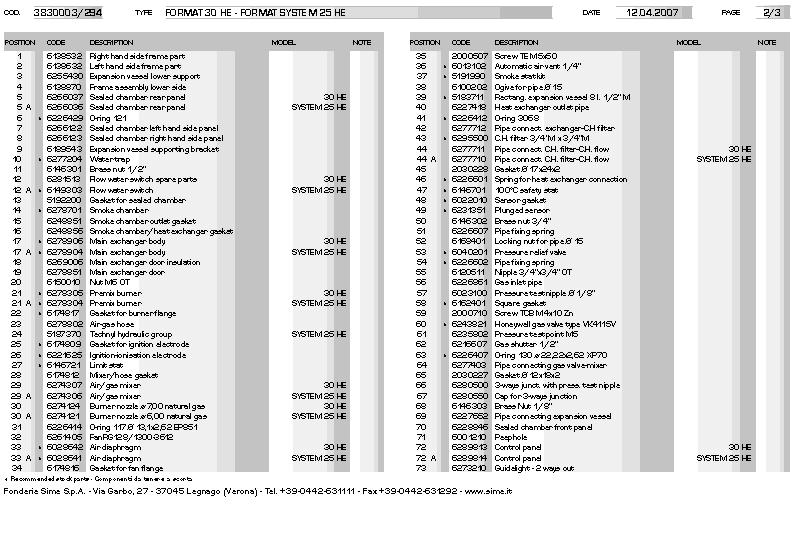
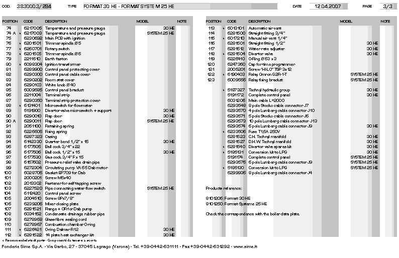
26 26 7 EXPLODED VIEWS
27 27
28 28
29 29
30 30
31 Dealing with Condensate Five suitable drainage points 1. Internal drain stack pipe 2. Waste water pipe * 3. External drain or gully * 4. Rainwater hoppers that carry both rain water and foul water * 5. Purpose-made soakaways * Care should be taken not to contaminate any Grey Water Systems Pipework Condensate pipework should be plastic, same as used for standard wastewater plumbing. Similarly the drainage system where the condensate discharges to should also be resistant to the acidic condensate. Connection to the internal trap in the boiler can be achieved by using a 20mm solvent weld socket. Pipework should be kept as short as possible. External runs should be avoided, but when necessary be a minimum of 3 meters in 32mm diameter pipework and lagged to avoid freezing, this also applies to pipe runs in unheated areas such as garages. To reduce the possibility of condensate being trapped in the pipe, the number of bends should be kept to a minimum. Pipework must be angled down from the boiler with a fall of at least 2.5. The pipework must be supported at a distance of 0.5m for inclined runs and 1.0m for vertical runs. Condensate traps Where the condensate drain is not sealed to the discharge connection a trap will be required. The water seal should be 38mm or more for external discharge and 75mm or more for internal discharge. When connecting to a external stack the trap should be located within the building. Stack Pipes Condensate connections should be at least 450mm above any bend at the bottom of a stack pipe in a single or multistory dwelling up to 3 storeys. There are specific requirements when connecting to a stack pipe serving multi-storey buildings greater than 3 storeys. All connections to stack pipes should avoid across flow between other Branch pipes. Soakaways Any soakaways have to be purpose-made and located as close to the boiler as possible, but clear of the buildings foundations and any buried services. The best option is to purchase a soakaway from a drainage manufacturer and install it to the manufacturers recommendation.
Format System 25 HE. Installation and servicing instructions
 GB Format System 25 HE Installation and servicing instructions IPX4D Format System 25 HE: Gas Council number 47-719-21 These appliances comply with the S.E.D.B.U.K. scheme, band A CONTENTS 1 DESCRIPTION
Format 30 HE. Installation and servicing instructions
 GB Format 30 HE Installation and servicing instructions IPX4D Format 30 HE: Gas Council number 47-719-21 These appliances comply with the S.E.D.B.U.K. scheme, band A CONTENTS 1 DESCRIPTION OF THE BOILER........................................................................
Ecomfort. Installation and servicing instructions
 GB Ecomfort Installation and servicing instructions IPX4D Ecomfort System 25 HE: Ecomfort 25 HE: Gas Council number 41-283-04 Gas Council number 47-283-06 Ecomfort 30 HE: Ecomfort 35 HE: Gas Council number
AUS. Format 34I-34E BF
 AUS Format 34I-34E BF Installation and servicing instructions CONTENTS 1 TECHNICAL FEATURES AND DIMENSIONS..................................................... 2 2 GENERAL REQUIREMENTS FOR INSTALLATION.................................................
INSTALLER INSTRUCTIONS
 INSTALLER INSTRUCTIONS CONTENTS 1 DCRIION OF THE BOILER................................................................. pag. 68 2 INSTALLATION...............................................................................
Format System 25 HE. User instructions. Please read the Important Notice within this guide regarding your boiler warranty
 UK ENSURE THAT THESE INSTRUCTIONS ARE LEFT FOR THE USER AFTER COMPLETION OF THE BENCHMARK SECTION Format System 25 HE User instructions 199838 Please read the Important Notice within this guide regarding
SIME FORMAT WALL HUNG BOILERS MODEL 34i AND MODEL 34e. cod A
 cod. 6272262A GENERAL DATA Heating Data Heat Output Input (Adjustable) (Adjustable) Format 34i 11.2 34KW 45 145MJ/hr Format 34e 11.2 34KW 45 145MJ/hr General Specifications FORMAT 34i 34e Main burner injectors
Mikrofill Ethos Condensing combination boiler. Maintenance Instructions 24cc
 Mikrofill Ethos Condensing combination boiler Maintenance Instructions 24cc IMPORTANT Benchmark Installation, Commissioning and Service Record Log Book is enclosed in your customer information pack. This
Format B. Installation and servicing instructions. Please read the Important Notice within this guide regarding your boiler warranty
 UK ENSURE THAT THESE INSTRUCTIONS ARE LEFT FOR THE USER AFTER COMPLETION OF THE BENCHMARK SECTION Format B Installation and servicing instructions 199838 Please read the Important tice within this guide
PLEASE LEAVE THIS INSTRUCTION WITH THE USER. Format B. Installation and servicing instructions
 GB PLEASE LEAVE THIS INSTRUCTION WITH THE USER Format B Installation and servicing instructions IPX4D Format 80 B: Gas Council number 47-283-07 Format 100 B: Gas Council number 47-283-08 These appliances
Alpha CD13R,18R and 24R
 Installation and Servicing Instructions Alpha CD3R,8R and 24R Wall Mounted, Fan Assisted, Room Sealed, Gas Fired, High Efficiency Condensing Regular Boiler Range For Technical help or for Service call...
Superior Mk.II. Installation, Servicing & User Instructions
 Superior Mk.II Installation, Servicing & User Instructions CONTENTS 1 TECHNICAL FEATURES AND DIMENSIONS...................................................... 1 2 GENERAL REQUIREMENTS FOR INSTALLATION..................................................
PLEASE LEAVE THIS INSTRUCTION WITH THE USER ECOMFORT PLUS 25 HE. User instructions
 GB PLEASE LEAVE THIS INSTRUCTION WH THE USER ECOMFORT PLUS 25 HE User instructions All descriptions and illustrations provided in this manual have been carefully prepared but we reserve the right to make
Super Combination Boilers
 Super Combination Boilers installation and servicing instructions CONTENTS 1 TECHNICAL FEATURES AND DIMENSIONS 1.1 INTRODUCTION.............................................................. 1 1.2 DIMENSIONAL
12.0 Servicing. Electrode Position Fig Annual Servicing Inspection (Cont) 4 ±0.5
 4 ±0.5") 4 ±0.5 12.0 Servicing 12.2 Annual Servicing Inspection (Cont) Flame Sensing 5 ±1 10 ±1 Position Fig. 45 Spark Ignition 5. Remove the clip securing the gas feed pipe to the air/gas venturi. Disconnect the
4 ±0.5 12.0 Servicing 12.2 Annual Servicing Inspection (Cont) Flame Sensing 5 ±1 10 ±1 Position Fig. 45 Spark Ignition 5. Remove the clip securing the gas feed pipe to the air/gas venturi. Disconnect the
Servicing manual. Wall-mounted condensing gas boiler 600 Series - 11S / 19S / 24S / 24C /2002 GB(EN) For trade use
 For trade use") GB122 7210 1300-12/2002 GB(EN) For trade use Servicing manual Wall-mounted condensing gas boiler 600 Series - 11S / 19S / 24S / 24C Please read thoroughly before attempting to diagnose fault List of contents
GB122 7210 1300-12/2002 GB(EN) For trade use Servicing manual Wall-mounted condensing gas boiler 600 Series - 11S / 19S / 24S / 24C Please read thoroughly before attempting to diagnose fault List of contents
PLEASE LEAVE THIS INSTRUCTION WITH THE USER. Ecomfort 30 HE. User instructions
 GB PLEASE LEAVE THIS INSTRUCTION WITH THE USER Ecomfort 30 HE User instructions CONTENTS OPERATING INSTRUCTIONS FOR THE USER 1.1 INTRODUCTION.................................................................................
MURELLE EV HE 25/55-30/55
 UK ENSURE THAT THESE INSTRUCTIONS ARE LEFT FOR THE USER AFTER COMPLETION OF THE BENCHMARK SECTION MURELLE EV HE 25/55-30/55 User instructions 199838 Please read the Important Notice within this guide regarding
Servicing manual. 600 Series - 11S / 19S / 24S / 24C. Wall-mounted condensing gas boiler. For trade use
 GB122 Servicing manual Wall-mounted condensing gas boiler 600 Series - 11S / 19S / 24S / 24C For trade use Please read thoroughly before attemting to diagnose fault 7217 4900 (03/2010) GB/IE List of contents
INSTALLATION AND SERVICING INSTRUCTIONS
 UK Cod. 6318139-10/2013 INSTALLATION AND SERVICING INSTRUCTIONS ENSURE THAT THESE INSTRUCTIONS ARE LEFT FOR THE USER AFTER COMPLETION OF THE BENCHMARK SECTION PLEASE READ THE IMPORTANT NOTICE WITHIN THIS
FORMAT DGT HE. User instructions. Please read the Important Notice within this guide regarding your boiler warranty
 UK ENSURE THAT THESE INSTRUCTIONS ARE LEFT FOR THE USER AFTER COMPLETION OF THE BENCHMARK SECTION FORMAT DGT HE 199838 User instructions Please read the Important Notice within this guide regarding your
INSTALLER INSTRUCTIONS
 FORMAT - ENGLISH CONTENTS INSTALLER INSTRUCTIONS 1 DESCRIPTION OF THE BOILER........................................................................ pag. 73 2 INSTALLATION.......................................................................................
Friendly Format. Installation and servicing instructions
 GB Friendly Format Installation and servicing instructions Friendly Format 80: Gas Council number 4771907 Friendly Format 80 E: Gas Council number 4771908 Friendly Format 100 E: Gas Council number 4771909
Super four. Installation and servicing instructions
 GB Super four Installation and servicing instructions CONTENTS 1 DESCRIPTION OF THE BOILER.............................................................................. 1 2INSTALLATION.............................................................................................
Service manual. Riva Plus HE. M296.28SR/C System boiler. Wall hung, fanflue, roomsealed, high efficiency gas boiler
 Wall hung, fanflue, roomsealed, high efficiency gas boiler Service manual Riva Plus HE Models G.C. ppl. No. M296.24SR/C 41-583-18 System boiler M296.28SR/C 41-583-19 System boiler Leave this manual adjacent
Performa System 12e, 18e, 24e & 28e
 Performa System 12e, 18e, 24e & 28e Gas Fired Wall Mounted System Boilers Installation and Servicing Instructions Please leave these instructions with the user Natural Gas Potterton Performa System 12e
MERIDIAN HE 30 C. User instructions. Please read the Important Notice within this guide regarding your boiler warranty
 UK ENSURE THAT THESE INSTRUCTIONS ARE LEFT FOR THE USER AFTER COMPLETION OF THE BENCHMARK SECTION MERIDIAN HE 30 C 199838 User instructions Please read the Important Notice within this guide regarding
Compact HE. High efficiency combi boiler. Installation & Servicing Instructions THESE INSTRUCTIONS TO BE RETAINED BY USER
 Compact HE High efficiency combi boiler Installation & Servicing Instructions THESE INSTRUCTIONS TO BE RETAINED BY USER Vokèra is a licensed member of the Benchmark scheme which aims to improve the standards
Wall hung combination boilers. This is a CAT II2H3+ appliance USER, INSTALLATION AND SERVICING INSTRUCTIONS SUPPORTED BY
 Wall hung combination boilers This is a CAT II2H3+ appliance SUPPORTED BY USER, INSTALLATION AND SERVICING INSTRUCTIONS Index Introduction... 3 User instructions...3 Introduction... 4 Controls and lighting...
A/23 MFFI - A/27 MFFI
 A/23 MFFI - A/27 MFFI G.C.N. 47-6-0 / 47-6-2 Servicing Instructions Type C Boilers LEAVE THESE INSTRUCTIONS ADJACENT TO THE GAS METER TABLE OF CONTENTS Page No.. SERVICING INSTRUCTIONS. Replacement of
Mynute. Installation & Servicing Instructions. 28e THESE INSTRUCTIONS TO BE RETAINED BY USER
 28e Installation & Servicing Instructions THESE INSTRUCTIONS TO BE RETAINED BY USER Contents Design principles & operating sequence Page 1.1 Principle components 2 1.2 Mode of operation 2 1.3 Safety devices
RMG IT ES PT GB FR BE
 RMG IT ES PT GB FR BE INSTALLER INSTRUCTIONS ENGLISH CONTENTS 1 DESCRIPTION OF THE BOILER........................................................................ pag. 38 2 INSTALLATION.......................................................................................
Installation & Servicing Instructions
 Installation & Servicing Instructions Baxi System 35/80 IE & 60/100 IE Gas Fired Wall Mounted System Boiler Please keep these instructions safe. Should you move house, please hand them over to the next
This is a Wall Mounted Powered Flue Condensing Combination Boiler Gas Fired Central Heating Unit.
 Installation & Service Instructions Performa System HE This is a Wall Mounted Powered Flue Condensing Combination Boiler Gas Fired Central Heating Unit. The boiler meets the requirements of Statutory Instrument
Servicing Instructions Type C Boilers G.C.N: LEAVE THESE INSTRUCTIONS ADJACENT TO THE GAS METER
 Servicing Instructions Type C Boilers G.C.N: 4-6-0 47-6-08 47-6-09 47-6-3 LEAVE THESE INSTRUCTIONS ADJACENT TO THE GAS METER TABLE OF CONTENTS Page No.. SERVICING INSTRUCTIONS. Replacement of Parts 3.2
Installation and Servicing Instructions
 Installation and Servicing Instructions Alpha HE CB25/33 and HE SY25 Wall Mounted, Fan Assisted, Room Sealed, Gas Fired, High Efficiency Condensing Boiler Range For Technical help or for Service call...
Alpha CombiMax 350 and 600
 Installation and Servicing Instructions Alpha CombiMax 350 and 600 Unvented Hot Water Store for use with the Alpha 240/280 Range of Gas Fired Combination Boilers For Technical help or for Service call...
Installation and Servicing Instructions. Alpha 240/280. Range of Wall Mounted, Fan Assisted, Room Sealed, Gas Fired Combination Boilers
 Installation and Servicing Instructions Alpha 240/280 Range of Wall Mounted, Fan Assisted, Room Sealed, Gas Fired Combination Boilers For Technical help or for Service call... ALPHA HELPLINE Tel: (0322)
Installation and Servicing Instructions. Alpha CD50
 Installation and Servicing Instructions Alpha CD50 Wall Mounted, Fan Assisted, Room Sealed, Gas Fired, High Efficiency, Condensing Combination Boiler with Unvented Hot Water Storage For Technical help
BRAVA DGT HE
 UK Cod. 6316191-08/2013 BRAVA DGT HE 25-30 - 35 INSTALLATION AND SERVICING INSTRUCTIONS ENSURE THAT THESE INSTRUCTIONS ARE LEFT FOR THE USER AFTER COMPLETION OF THE BENCHMARK SECTION PLEASE READ THE IMPORTANT
ATMOSPHERIC GAS BOILER INSTALLATION, OPERATING AND MAINTENANCE MANUAL
 STREBEL GENEVA CE ATMOSPHERIC GAS BOILER INSTALLATION, OPERATING AND MAINTENANCE MANUAL INDEX TABLE 1 TECHNICAL DATA SECTION 1 SECTION 2 SECTION 3 SECTION 4 SECTION 5 SECTION 6 SECTION 7 SECTION 8 SECTION
GB24 & GB30. User Manual
 GB24 & GB30 User Manual BOILER OUTPUT To Domestic Hot Water:To Central Heating: GB24/30 Minimum 8.0 kw (27,296 Btu/h) GB24 Maximum 24.2 kw (82,570 Btu/h) GB30 Maximum 30.3 kw (103,384 Btu/h) GB24/30 Minimum
Installation and Servicing Instructions. Alpha CB50
 Installation and Servicing Instructions Alpha CB50 Wall Mounted, Fan Assisted, Room Sealed, Gas Fired Combination Boiler with Unvented Hot Water Storage For Technical help or for Service call... ALPHA
MAINTENANCE AND SERVICE GUIDE
 c Dimensions MAINTENANCE AND SERVICE GUIDE System II 80 and 100 Central Heating Fanned Flue Boiler Sizes in mm Flue types: C 12 or 42: horizontal C 32 xx: vertical concentric C 32 xy: Twin flue Boiler
Installation and Servicing Instructions. Alpha CD24C/32C
 Installation and Servicing Instructions Alpha CD24C/32C Range of Wall Mounted, Fan Assisted, Room Sealed, Gas Fired, High Efficiency Condensing Combination Boilers For Technical help or for Service call...
VICTRIX 90 VICTRIX 115 Wall-hung condensing boilers for high power
 VICTRIX 90 VICTRIX 115 Wall-hung condensing boilers for high power VICTRIX 90 is the new wall-hung condensing boiler for room heating only, set-up for independent functioning and for that in cascade mode
MULTIPOINT FF Room Sealed Fan-Assisted Water Heater
 Please leave these instructions with the user MULTIPOINT FF Room Sealed Fan-Assisted Water Heater User Operating, Installation and Servicing Instructions 6 720 607 160 (04.02) JS Natural Gas Main Multipoint
TEMPRA. Wall Mounted Fan Flue System boiler. Wall mounted fanned flue boiler INSTALLATION AND USE INSTRUCTIONS. Appr. nr. B A - CE 0063 AQ 2150
 Wall Mounted Fan Flue System boiler Appr. nr. B 94.04 A - CE 0063 AQ 2150 Phone numbers: Installer Service Engineer Serial N Wall mounted fanned flue boiler INSTALLATION AND USE INSTRUCTIONS Please read
USER GUIDE VOGUE COMBI GEN2 C26 C32 C40
 USER GUIDE VOGUE COMBI GEN2 C26 C32 C40 When replacing any part on this appliance, use only spare parts that you can be assured conform to the safety and performance specification that we require. Do not
ProCon Streamline Gas Condensing Boiler. Installation and Operating Manual.
 1 MHG Heating Ltd ProCon Streamline Gas Condensing Boiler. Installation and Operating Manual. Unit 4 Epsom Downs Metro Centre, Waterfield, Tadworth, Surrey, KT20 5LR Telephone 08456 448802 Fax 08456 448803
USERS GUIDE. Esprit eco 24, 30. For installation guide see reverse of book
 USERS GUIDE Esprit eco 24, 30 For installation guide see reverse of book When replacing any part on this appliance, use only spare parts that you can be assured conform to the safety and performance specification
INSTALLATION MANUAL. Ecoline Geo RI HP PLEASE LEAVE THIS MANUAL WITH THE OSO UNIT AFTER INSTALLATION
 PLEASE LEAVE THIS MANUAL WITH THE OSO UNIT AFTER INSTALLATION Ecoline Geo RI HP INSTALLATION MANUAL The Ecoline GEO is an indirect unvented cylinder designed and approved for use with a heat pump. The
Osprey 2 CFL
 Osprey 2 CFL 125-150 - 180-220 Gas Fired Floor Standing Boiler Installation and Servicing Instructions Please leave these instructions with the user Natural Gas Potterton Osprey 2 CFL 125 G.C.N o 41 590
Bosch Group. 15SBi / 24SBi. WALL MOUNTED BOILERS FOR CENTRAL HEATING and Indirect supply of domestic hot water
 Bosch Group 15SBi / 24SBi WALL MOUNTED BOILERS FOR CENTRAL HEATING and Indirect supply of domestic hot water INSTALLATION AND SERVICING INSTRUCTIONS 24SBi This appliance is for use with Natural Gas or
i 24, i 30, i 35 combination boilers USER GUIDE For Installation Guide see reverse of book UIN A05 October 2017
 24 1 2 23 3 4 5 20 6 I 19 7 18 8 9 15 14 11 13 12 i 24, i 30, i 35 combination boilers USER GUIDE For Installation Guide see reverse of book i 24 OFF MAX E STATUS BURNER RESET MIN PRE MIN MAX HEAT PREHEAT
Wall hung combination boiler PROTHERM 23 BTVE
 Wall hung combination boiler PROTHERM 23 BTVE User, Installation and Servicing Instructions 6187 The boiler serial number is marked on the label attached to the inside of the drop down door. Refer to the
ESS. Installation & Servicing Instructions THESE INSTRUCTIONS TO BE RETAINED BY USER
 ESS Installation & Servicing Instructions THESE INSTRUCTIONS TO BE RETAINED BY USER Contents Design principles & operating sequence Page 1.1 Principle components 2 1.2 Mode of operation (at rest) 2 1.3
TAHITI CONDENSING KR 55 - KR 85
 IST 03 C 351-01 TAHITI CONDENSING KR 55 - KR 85 GB INSTALLATION USE AND MAINTENANCE Dear Customer, Thank you for choosing and buying one of our boilers. Please read these instructions carefully. They will
User's Instructions. Alpha CD25X/28X. Range of Wall Mounted, Fan Assisted, Room Sealed, Gas Fired, High Efficiency Condensing Combination Boilers
 User's Instructions Alpha CD5X/8X Range of Wall Mounted, Fan Assisted, Room Sealed, Gas Fired, High Efficiency Condensing Combination Boilers For Technical help or for Service call... ALPHA HELPLINE Tel:
CBX 24, 32 & 38 SBX 30
 751030 MANUAL (NEW) 21/9/10 08:39 Page 1 Eden X Type CBX 24, 32 & 38 SBX 30 INSTALLATION AND SERVICING INSTRUCTIONS TO BE GIVEN TO THE USER 0086 EC 87/BP/35 G.C. Appliance No. 47-260-05 (Eden CBX 24) G.C.
Gas Instantaneous Water Heater
 6 720 607 823 GB (06.06) SM Installation and Operating Instructions Gas Instantaneous Water Heater WR10..B... WR11..B... With electronic ignition and triple safety system consisting of ionisation detector,
PLEASE LEAVE THIS MANUAL WITH THE OSO UNIT AFTER INSTALLATION INSTALLATION MANUAL
 PLEASE LEAVE THIS MANUAL WITH THE OSO UNIT AFTER INSTALLATION SOLARCYL IM/SC INSTALLATION MANUAL This manual gives detailed advice for installation and should be read carefully prior to fitting any unvented
Baxi Barcelona System
 Baxi Barcelona System Wall Mounted Powered Flue Condensing Boiler Gas Fired Central Heating Unit Comp N o 243612 - Iss 5-4/00 Please leave these Instructions with the User Installation and Servicing Instructions
Compact. Installation & Servicing Instructions THESE INSTRUCTIONS TO BE RETAINED BY USER
 Compact Installation & Servicing Instructions THESE INSTRUCTIONS TO BE RETAINED BY USER Contents Design principles and operating sequence Page 1.1 Principle components 2 1.2 Central heating mode 2 1.3
HALSTEAD Ace INSTALLATION & SERVICING INSTRUCTIONS FOR THE
 INSTALLATION & SERVICING INSTRUCTIONS FOR THE HALSTEAD Ace FULLY AUTOMATIC FAN ASSISTED BALANCED FLUE COMBINATION BOILER FOR USE WITH NATURAL GAS B R I T I S H M A D E B O I L E R S G. C. APPLIANCE No.
USER GUIDE VOGUE MAX SYSTEM
 USER GUIDE VOGUE MAX SYSTEM 15 18 26 32 When replacing any part on this appliance, use only spare parts that you can be assured conform to the safety and performance specification that we require. Do not
Service manual GARDA HE MK2. M96A.24SM/B Combi boiler M96A.28SM/B Combi boiler
 Wall hung, fan flue, room sealed, high efficiency gas boiler Service manual GRD HE MK2 Models: G.C. ppl. No. M96.24SM/ 47---583---15 Combi boiler M96.28SM/ 47---583---16 Combi boiler Leave this manual
USER GUIDE LOGIC HEAT H
 USER GUIDE LOGIC HEAT H 12 15 18 24 30 When replacing any part on this appliance, use only spare parts that you can be assured conform to the safety and performance specification that we require. Do not
Logic+ Combi
 USER GUIDE Logic+ Combi 24 30 35 When replacing any part on this appliance, use only spare parts that you can be assured conform to the safety and performance specification that we require. Do not use
SERVICE MANUAL RIVA COMPACT M90E.24S M90E.28S M90E.32S Wall hung, fan flue, room sealed gas boiler
 Wall hung, fan flue, room sealed gas boiler SERVICE MNUL RIV COMPCT Models: G.C. ppl. No. M90E.24S 47--970--17 M90E.28S 47--970--18 M90E.32S 47--970--21 Leave this manual adjacent to the gas meter iasi
INSTALLATION AND MANINTENANCE INSTRUCTIONS
 INSTALLATION AND MANINTENANCE INSTRUCTIONS Appr. Nr. A 9503 T - 0085 AQ 0765 PEGASUS F2 T HIGH EFFICIENCY GAS-FIRED CAST-IRON BOILERS Models 51-68 - 85-102 2 Contents 1. General technical data 2. Dimensional
System s30. User Guide FAN POWERED HIGH EFFICIENCY MODULATING DOMESTIC CONDENSING GAS SYSTEM BOILER
 System s30 User Guide FAN POWERED HIGH EFFICIENCY MODULATING DOMESTIC CONDENSING GAS SYSTEM BOILER When replacing any part on this appliance, use only spare parts that you can be assured conform to the
Installation and Servicing Instructions. Alpha CD25C/28C/35C
 Installation and Servicing Instructions Alpha CD25C/28C/35C Range of Wall Mounted, Fan Assisted, Room Sealed, Gas Fired, High Efficiency Condensing Combination Boilers For Technical help or for Service
Unvented Calorifier Range. Operating and Maintenance Manual. For Models & 500
 Unvented Calorifier Range. Operating and Maintenance Manual. For Models 125 300 & 500 Telephone 08456 448802 Fax 08456 448803 Emial info@mhgheating.co.uk Web www.mhgheating.co.uk TABLE OF CONTENTS. Section
MULTIPOINT BF Gas Fired Balanced Flue Water Heater
 Please leave these instructions with the user MULTIPOINT BF Gas Fired Balanced Flue Water Heater User Operating, Installation and Servicing Instructions 6 720 607 090 (03.12) JS Natural Gas Main Multipoint
User's Instructions. Alpha CD24C/32C. Range of Wall Mounted, Fan Assisted, Room Sealed, Gas Fired, High Efficiency Condensing Combination Boilers
 User's Instructions Alpha CD24C/32C Range of Wall Mounted, Fan Assisted, Room Sealed, Gas Fired, High Efficiency Condensing Combination Boilers For Technical help or for Service call... ALPHA HELPLINE
User's Instructions. Alpha CB50
 User's Instructions Alpha CB50 Wall Mounted, Fan Assisted, Room Sealed, Gas Fired Combination Boiler with Unvented Hot Water Storage (From Boiler Serial No. 27B32500001) For Technical help or for Service
SIGMA. Wall Mounted Cast Iron, Gas Fired Boiler for Central Heating Fan Assisted, Room Sealed, Electronic Flame Ignition and Control
 SIGMA Wall Mounted Cast Iron, Gas Fired Boiler for Central Heating Fan Assisted, Room Sealed, Electronic Flame Ignition and Control INSTALLATION AND SERVICING INSTRUCTIONS Sigma 20-40 GC N 4-267-7 Sigma
PLEASE LEAVE THIS MANUAL WITH THE OSO UNIT AFTER INSTALLATION INSTALLATION MANUAL
 PLEASE LEAVE THIS MANUAL WITH THE OSO UNIT AFTER INSTALLATION 0 RD 0 RI 0000-06 IM/ IM/a INSTALLATION MANUAL This manual gives detailed advice for installation and should be read carefully prior to fitting
Mikrofill Ethos Condensing combination boiler
 Mikrofill Ethos Condensing combination boiler User Instructions 24cc CE Mark Mikrofill gas appliances comply with the requirements contained in CE Mark documents contained with European directives applicable
FORMAT DGT HE. Please read the Important Notice within this guide regarding your boiler warranty
 UK ENSURE THAT THESE INSTRUCTIONS ARE LEFT FOR THE USER AFTER COMPLETION OF THE BENCHMARK SECTION FORMAT DGT HE 199838 Installation and servicing instructions Please read the Important Notice within this
TC MODULE (FFD) (with Gas Hob)
 (with Gas Hob)") TC MODULE (FFD) (with Gas Hob) Installation Instructions REMEMBER: when replacing a part on this appliance, use only spare parts that you can be assured conform to the safety and performance specification
TC MODULE (FFD) (with Gas Hob) Installation Instructions REMEMBER: when replacing a part on this appliance, use only spare parts that you can be assured conform to the safety and performance specification
This is a Wall Mounted Powered Flue Condensing Combination Boiler Gas Fired Central Heating Unit.
 Installation & Service Instructions Performa 30 HE This is a Wall Mounted Powered Flue Condensing Combination Boiler Gas Fired Central Heating Unit. The boiler meets the requirements of Statutory Instrument
Bosch Group. 15SBi / 24SBi. WALL MOUNTED BOILERS FOR CENTRAL HEATING and Indirect supply of domestic hot water
 Bosch Group SBi / SBi WALL MOUNTED BOILERS FOR CENTRAL HEATING and Indirect supply of domestic hot water INSTALLATION AND SERVICING INSTRUCTIONS SBi This appliance is for use with Natural Gas or LPG (Cat
Service manual. Riva Plus HE ERP. Wall hung, fanflue, roomsealed, high efficiency gas boiler. Leave this manual adjacent to the gas meter
 Wall hung, fanflue, roomsealed, high efficiency gas boiler Service manual Riva Plus HE ERP Models RIV PLUS HE 24S ERP RIV PLUS HE 28S ERP G.C. ppl. No. 41-583-31 SYSTEM BOILER 41-583-32 SYSTEM BOILER Leave
SABRE. Installation & Servicing Instructions THESE INSTRUCTIONS TO BE RETAINED BY USER
 SABRE Installation & Servicing Instructions THESE INSTRUCTIONS TO BE RETAINED BY USER INTRODUCTION The Sabre range of appliances are combined central heating and domestic hot water boilers, which by design
Mynute 24m Installation & Servicing Instructions
 Mynute 24m Installation & Servicing Instructions THESE INSTRUCTIONS TO BE RETAINED BY USER Contents Design principles & operating sequence Page 1.1 Principle components 2 1.2 Mode of operation 2 1.3 Safety
INSTALLATION MANUAL. RD SERIES Digital Electric Water Heater Wall-hung Unvented
 INSTALLATION MANUAL RD SERIES Digital Electric Water Heater Wall-hung Unvented WELCOME Dear Customer, Thank you for choosing the RD Series electric water heater, with an exclusive electronic temperature
Ace and Ace High. Installation and Servicing Instructions To be left with user adjacent to gas meter. Wall Mounted Gas Combination Boiler
 Ace and Ace High Wall Mounted Gas Combination Boiler Installation and Servicing Instructions To be left with user adjacent to gas meter G. C. APPLIANCE No. 41 333 77 Ace G. C. APPLIANCE No. 41 333 78 Ace
SIGMA WALL MOUNTED CAST IRON, GAS FIRED BOILER FOR CENTRAL HEATING FAN ASSISTED, ROOM SEALED, ELECTRONIC FLAME IGNITION AND CONTROL
 SIGMA WALL MOUNTED CAST IRON, GAS FIRED BOILER FOR CENTRAL HEATING FAN ASSISTED, ROOM SEALED, ELECTRONIC FLAME IGNITION AND CONTROL G.C. NO: Sigma 30 FF 4-267 - 07 Sigma 40 FF 4-267 - 08 Sigma 50 FF 4-267
INSTALLATION AND SERVICING INSTRUCTIONS
 C1 WALL MOUNTED COMBINATION BOILER FOR CENTRAL HEATING AND MAINS FED DOMESTIC HOT WATER INSTALLATION AND SERVICING INSTRUCTIONS 0 I This appliance is for use with Natural Gas. GC NUMBER 47 311 53 (N.G.)
USER INSTRUCTIONS & CUSTOMER CARE GUIDE Si II SERIES
 24-28Si II SERIES G.C. NUMBERS APPLIANCE NATURAL GAS L.P.G. 24Si II 47 311 65 47 311 66 28Si II 47 311 67 47 311 68 USER INSTRUCTIONS & CUSTOMER CARE GUIDE EXCELLENCE COMES AS STANDARD CONTENTS Page No.
With a power output ranging from 13kW to 24kW, they provide the flexible answer for the majority of traditional installation scenarios.
 Alpha Regular Boilers CDR Range CDR heating-only boilers are for use on open-vented or using the Alpha sealed system kit sealed systems. When fitted with a storage cylinder, they are capable of supplying
Planet Super4F.S. Installation & Servicing Instructions
 GB Planet Super4F.S. Installation & Servicing Instructions INSTALLER INSTRUCTIONS CONTENTS DESCRIPTION OF THE BOILER........................................................................ page 2GENERAL
kw Btu/h Metres Feet l/min. Gal/min C C
 80ic RSF WALL MOUNTED COMBINATION BOILER FOR CENTRAL HEATING AND MAINS FED DOMESTIC HOT WATER INSTALLATION AND SERVICING INSTRUCTIONS 6 720 605 553 PT 2000 11 Cat: II 2H3+ GC NUMBER NG: 47 311 43 LPG:
USERS GUIDE. LOGIC+ Combi 24, 30, 35
 USERS GUIDE LOGIC+ Combi 24, 30, 35 When replacing any part on this appliance, use only spare parts that you can be assured conform to the safety and performance specification that we require. Do not use
Baxi Combi 80 Maxflue
 Please leave these instructions with the user Baxi Combi 80 Maxflue Gas Fired Wall Mounted Combination Boiler Installation and Servicing Instructions Natural Gas Baxi Combi 80 Maxflue G.C.N o 47 075 07
Open Vented Condensing Boilers
 Dimplex 18 OV Dimplex 32 OV Open Vented Condensing Boilers User s Operating Instructions These instructions should be left with the user Dimplex Boilers 2008 CONTENTS SECTION DESCRIPTION PAGE 1.0 Using
Installation and Servicing Instructions. Alpha CD25X/28X
 Installation and Servicing Instructions Alpha CD25X/28X Range of Wall Mounted, Fan Assisted, Room Sealed, Gas Fired, High Efficiency Condensing Combination Boilers For Technical help or for Service call...
WARMCAIR. Condensing Air & Water Heater. High Efficiency Downflow Condensing Air & Water Heater USERS INSTRUCTIONS
 WARMCAIR Condensing Air & Water Heater Publication No. ZZ 1449-2 September 2016 High Efficiency Downflow Condensing Air & Water Heater USERS INSTRUCTIONS Warmcair C10DW - G.C. No. 43-417-59 Warmcair C16DW