Chapter 10. HVAC System
|
|
|
- Shanon Franklin
- 6 years ago
- Views:
Transcription
1 Standardized Technical Specification Bi-Level Passenger Rail Cars for Intercity Corridor Service Chapter 10 HVAC System Revision C
2 Table of Contents 10-1 Table of Contents 10.0 HVAC System Overview General Requirements Design Parameters Comfort Requirements Interior Noise Air Conditioning Heating Ventilation Dampers Fresh Air Dampers Diversion Dampers Controls Sensors Use of Controls Status Display Ventilation Cut-Out Switch Freeze Protection
3 Revision Status 10-2 Revision Status Spec Section # Description Date of Revision New Revision Level Initial release A 6/29/08 Minor edits A1 7/22/08 Incorporated Bob Highfill s edits/comments Incorporated A.2 edits and comments, also minor edits Incorporated A.3 edits and comments with changes to hermitically sealed units and changes to layover mode. Incorporated A.3 Leo edits and comments, also minor edits Formatted and Conformed to Style Guide Author A. Di Iorio (PB) A. Di Iorio (PB) A.2 7/29/09 CLC A.3 10/1/09 A.3 Leo 9/8/09 A.4 9/8/09 A. Di Iorio (PB) L Hoyt (CT) A. Di Iorio (PB) A.5 9/9/09 CLC Incorporated Stan s edits/comments A.6 10/30/09 CLC Final Formatting B 11/2/09 CLC Spec. Comp. Incorporated Stan s edits/comments & Conformed to Style Guide B.1 12/21/09 CLC Edited Specified Components per Stan. B.2 12/23/09 CLC Incorporated Stan s edits/comments w/ tracked changes Incorporated Stan s response to Interfleet s, PB s & Virginkar s comments. Accepted all tracked changes and formatted B.2 2/5/10 CLC B.2 3/9/10 CLC C 3/19/10 CLC
4 HVAC System HVAC System 10.1 Overview Each car shall be equipped with two identical units to provide Heating, Ventilation and Air Conditioning (HVAC) to the car. The HVAC units shall be removable and self-contained, and shall utilize scroll compressors and R400-series refrigerants for cooling. Temperature control shall be provided by a microprocessor-based integrated HVAC control system that monitors ambient outside and inside temperatures and adjusts the system s cooling and heating functions to maintain a comfortable inside temperature and humidity level throughout the range of environmental and climatic conditions identified in Caltrans Specification Dampers on the fresh air intake vents shall control the amount of outside air taken in by the HVAC system. Diversion dampers at each end of the car shall control the amount of conditioned air being delivered to the upper or lower level, to adjust and maintain equal temperatures on both levels. Heating shall be provided by overhead heat in the HVAC units, with additional heating provided by floor heaters along the base of the side walls in the car interiors. Freeze protection shall be provided on the side door thresholds and all fresh water system components that may be exposed to freezing conditions General Requirements The HVAC system shall provide a comfortable temperature controlled environment of the interior areas of all cars as follows: The cars shall be designed to operate in all environmental and climatic conditions identified in Caltrans Specification The car s interior temperature, including the engineer s cab, shall be maintained to the specified value (68 F - 76 F) under all specified circumstances. The lower level shall receive adequate airflow from the HVAC to maintain the specified interior temperature and be able to restore the interior temperature after the side entrance doors are opened and the interior temperature is impacted by the ambient outside temperature without affecting the upper level temperatures. Passenger load shall be assumed to be AW3 for heat load calculations. Heat and cooling requirements shall include the opening of both sets of lower level side doors on alternating sides of the car every 15 minutes and held open for 2 minutes, to simulate passenger loading and unloading in all outside ambient temperatures identified in Caltrans Specification Ambient conditions as specified and heat losses due to train motion shall be included in HVAC system performance evaluation. Air flow losses due to door and carbody leakage.
5 HVAC System 10-4 A microprocessor-based, integrated HVAC system shall be provided. The system shall be designed to maintain the specified interior passenger area temperature and humidity and to also assure adequate interior ventilation. The Contractor shall prepare, and submit for the Customer's approval during design review, a detailed heating and cooling load analysis along with recommended heating, cooling and ventilation capacities. DR In no case shall the heating capacity be less than 40 kilowatt (kw) not including the forced air control cab heater, nor shall the refrigeration capacity be less than 244,000 BTU/Hr. The HVAC unit manufacturer shall conduct qualification testing to verify that the units provide the design heating and cooling capacity per ASHRAE Standard This testing is further discussed in Chapter 19. The HVAC system shall be powered primarily from the 480VAC, 3-phase, 60 Hz supply. The temperature controls shall operate from the 120VAC, 1-phase, 60 Hz supply, and the freeze protection circuits shall operate from the 120VAC, 3-phase, 60 Hz supply. The HVAC system shall be designed to perform at the nominal voltages and operate within the voltage and frequency tolerance ranges specified in Caltrans Specification To minimize the effects of motor inrush currents on the head end power system, the controls shall incorporate a method to provide staggered starting of the refrigerant compressor motors. The start up timing shall be set to stagger the startup of the A/F-end unit at least 15 seconds before the B-end unit. Electric baseboard floor heaters, mounted behind stainless steel guards, shall be provided along both side walls, upper and lower levels. Baseboard heaters shall also be provided in the engineer s cab in addition to the forced air heater described in Chapter 16. Freeze protection is an essential function of the heating system. Freeze protection shall turn the heaters on when ambient outside temperatures drop below 40 F, and shut off when temperatures rise to 50 F. The HVAC system shall be controlled by a solid-state temperature control using a sufficient number of temperature sensors to properly regulate heating and cooling in response to temperature changes inside and outside the car. Temperature sensors in the car body shall be located to accurately reflect temperature changes without being unduly influenced by external heat sources or solar radiation. HVAC system circuit breakers and temperature control adjustment devices shall be located in the electrical locker and be accessible only to the operating crew. Circuit breakers, controls and relays shall be inaccessible to the passengers. The HVAC unit shall be a fully hermetically sealed system, without threaded components, or other non-welded fittings, except for two service ports equipped with high quality industrial Schrader valves. The performance of the entire assembled HVAC system as installed in a completed car shall be verified at the Climate Room Test specified in Chapter 19.
6 HVAC System Design Parameters The following parameters are to be assumed in the design of the cooling system: Ambient Temperature 110 F Dry Bulb/82 F Wet Bulb, with 125 F air entering the condenser Solar Load Equivalent to 35 North Latitude, maximum solar heat rate, in accordance with ASHRAE calculation methods Passenger Heat Load 440 BTU/hr/person at a heat ratio of 0.60 Number of Passengers 90 seated passengers and up to 130 standees (load level AW3) Carbody Heat Transmission In accordance with the Contractor s car body insulation design to meet the requirements of this Specification, and not less than 1200 BTU/hr- F Maximum Infiltration (Fresh Air) 1,575 Cubic Feet per Minute (cfm) Other Heat Loads Normal car lighting, electrical equipment and appliance loads The following parameters are to be assumed in design of the heating system: Ambient Temperature -30 F Dry Bulb Carbody Heat Transmission In accordance with the Contractor s car body insulation design to meet the requirements of this Specification, and not less than 1200 BTU/hr- F Maximum Infiltration (Fresh Air) 1575 cfm Solar Load None Passenger Load None Other Heat Loads Quiet car lighting only (see Chapter 11) 10.4 Comfort Requirements Interior The following temperatures shall be maintained within the car s upper and lower levels (including toilet rooms and cab) when the associated ambient outside temperatures are present: Outside Ambient Interior Car Temperature Below -30ºF As system will provide -30ºF to +60ºF 70 F ± 2 F 60ºF to 130ºF 74 F ± 2 F (depending on functioning with or without reheat cycle) Above 130ºF As system will provide. Layover Cool Mode 85 F ± 2 F Layover Heat Mode 50ºF ± 5 F During all modes of air conditioning, the interior relative humidity shall not exceed 60%.
7 HVAC System 10-6 Except within the area of the side doors and vestibules, the HVAC system shall maintain a temperature variation, within both the upper and lower levels, of the following: Vertical variation: (On any vertical line, 4 in. above floor to 43 in. above floor, not closer than 6 in. from walls, and not closer than 20 in. from doors): 5 F maximum difference between end points of the vertical line. Horizontal variation: (horizontal planes measured 4 in., 43 in. and 67 in. from floor, not closer than 6 in. from walls and not closer than 20 in. from doors.): The temperature at any point within each plane should not exceed ± 3 F from the average temperature in that plane. The average car temperature, including the upper and lower levels, shall recover within 2 F of the required interior car temperature within three minutes maximum following a two minute door opening on one side of the vehicle. It shall be demonstrated that this requirement can be met during two hours of continuous door cycling of two minutes open and 15 minutes closed at the design conditions in both heating and cooling modes. Temperature variation between the upper and lower levels shall not exceed 4 F at any time Noise The overall HVAC system shall be designed to minimize noise in the passenger and crew areas of the car. The noise level from the HVAC system shall not exceed the values in the following table. Particular care shall be required at the return air grilles, cab supply vents and galley ceiling air diffusers. With the car stationary and the HVAC unit in its loudest cooling mode: Interior noise level: Coach seating areas, cab, toilet rooms and galley Exterior noise level As specified in Chapter Decibels (Acoustic) (dba) max (15 ft from centerline of car) 10.5 Air Conditioning The cars shall be cooled using electromechanical equipment that has been proven in rail service. Two self contained, hermetically sealed HVAC units shall be provided on each car. The HVAC units shall be identical, one located in each equipment room. The same unit shall be used on all car types. The units shall be designed for a 400-series refrigerant, conforming to 40CFR Part 82. components within the unit, such as seals, shall be compatible with synthetic lubricants. Each HVAC unit shall supply conditioned air to the entire car, upper and lower levels, through the use of a splitter in the supply air ducts. Separate car air temperature sensors shall be used to provide independent floor heat control for the upper and lower level. The control cab in the cab/baggage car shall also have its own local thermostat. The air conditioning system shall be designed and adequately sized to maintain interior car temperature as specified measured at the return air grille at the normal ambient conditions. For ambient temperatures greater than 130ºF, the air conditioning system shall be capable of maintaining cooling at a reduced capacity. Application and integration of the system is to be in
8 HVAC System 10-7 accordance with the recommendation of the air conditioning manufacturer who shall also specify air flow requirements. Each HVAC unit shall be totally self-contained, easily removable, and shall consist of a compressor/condenser section and an evaporator section with electric heating units. Condenser air inlet shall be through the car sidewall, with discharge through the equipment room floor. A convenient means shall be provided to install and remove the units from the equipment room through the condenser air intake door opening using a fork lift truck. Tapered guide pins or other suitable method shall be provided to guide the unit into its position in the equipment room. The unit shall be properly supported on a fork lift compatible pallet so as to reduce the amount of wear and tear on the equipment as a function of removing and reinstalling the units over the vehicle s lifetime. The installation and removal process, including removing and installing all mounting hardware, and electrical connections, shall be demonstrated on each car equipment room type for Customer approval at the design review. DR The HVAC unit shall be mounted above drip pans. The drip pans shall catch the moisture (condensate) created by the evaporator. The drip pans shall be designed and constructed to prevent sloshing of the condensate while maintaining equipment room pressurization. The drained condensate shall be directed to the roadbed through the equipment room floor structure without leakage into the equipment room or car structure and shall not be discharged on car structure, wheels, brakes or electrical equipment. The exit of the condensate drain lines under the car shall be arranged in an approved manner to be readily accessible for maintenance, be protected from clogging and rodent entry, and as required for servicing the HVAC units. The refrigeration system shall include, at a minimum, the following components and features: The units shall be designed for an R400-series refrigerant, conforming to 40CFR Part 82. components within the unit, such as seals, shall be compatible with synthetic lubricants. A single scroll with modulation of two scroll-type refrigerant compressors working in tandem shall provide, at a minimum, both 50% and 100% capacity control. Compressor shutdown control shall be by means of a pump down cycle that senses suction line pressure. Refrigerant compressor crankcase heaters. Refrigerant control box, containing, pressure switches, service switch, etc. Direct drive condenser fan and motor assemblies. Condenser coil assemblies with in. thick copper fins on 0.38 in. diameter copper tubing at a spacing of 8 fins per in. One charging and one evacuation port equipped with high quality Schrader valves and sealing metal caps. Suction accumulator. Filter drier. Discharge line check valves, and moisture and liquid indicators. Direct drive supply air blower and motor assemblies. Liquid line solenoid valves (2 per unit). Thermal expansion valves (2 per unit).
9 HVAC System 10-8 Evaporator coil assemblies with two horizontally split sections for modulated and full cooling. The assembly shall have in. thick copper fins on 0.38 in. diameter copper tubing at a spacing of 10 fins per inch. High, low, and modulation pressure switches. Unit removal shall not require a full purge and charge of the refrigerant system. Means shall be incorporated to allow a full pump down of the system and isolation of the refrigerant circuit by use of permanently installed appropriate valves to allow efficient removal and reinstallation of the unit. For cab compartment air conditioning, refer to Chapter Heating The cars shall be electrically heated. The system shall compensate for carbody losses and fresh air heating loads. The heating system shall be designed and adequately sized to maintain interior temperature as specified throughout the car measured at the return air grille at the normal ambient conditions. Overhead heat shall be divided into stages. The size of each stage shall be chosen and controlled so that cycling of the heating contactors is minimized. The overhead heaters shall be protected against overheating caused by the loss of sufficient air over the heater elements. Two protection devices shall be installed adjacent to each heater element and shall be used as temperature sensing devices to detect an overheat condition. Together, these devices shall offer two levels of protection. The first device shall disable the overhead heater by disabling the control circuit to the heater. The second device shall be used for backup protection, set slightly higher than the first, and, upon detection of excessive temperature, shall disable overhead heater and energize the shunt trip coil of the overhead heat circuit breaker such that it will trip. The first device shall reset automatically, and the second device shall require a manual reset. The protection method shall be reviewed by the Customer at the design review. DR The side wall heaters shall be enclosed by sloping top heater grilles with perforated holes. The grilles shall be designed to provide a smooth transition with the side wall. The grilles shall be designed to prevent debris from entering the heating space and contacting the heater elements. The grilles shall be fitted with interior baffles to assist the convective air flow. The temperature of any portion of the grilles that could come in contact with passengers shall not exceed 125 F at nominal supply voltage. Antifreeze protection (activated at an outside temperature of 40 F) shall be provided for the side door thresholds, side door pockets, water tank and water drain valves, each protected by independent circuit breakers. Refer to Chapter 15 for Water and Waste System. In addition, each equipment room shall be equipped with its own self-contained heater unit that operates independently of the main HVAC temperature controls. The equipment room heaters shall turn on when the ambient temperature in the equipment room drops to 40 F, and shall turn off when the equipment room temperature rises to 50 F. Layover heat shall be supplied by the sidewall floor heat and shall maintain an interior temperature of 50 F ± 5 F, including the cab. During layover heating, the evaporator fans shall not operate and the fresh air shall be shut off.
10 HVAC System 10-9 The heating system shall include, at a minimum, the following components and features: Staged forced air electrical overhead heat. Heater over temperature protection devices. Two stages of sidewall heaters. For additional cab compartment heating requirements, refer to Chapter Ventilation The ventilation system shall include, at a minimum, the following components and features: Exterior fresh air intakes with water eliminators and filters Electrically motorized fresh air dampers Frame type disposable air filters Air distribution ducts Electrically motorized supply air diversion dampers Air diffusers and grilles Exhaust ducts Exhaust fans Emergency fan switches Ventilation of the car shall be accomplished by blower fans supplied as part of the HVAC units. Fresh air shall enter the car through stainless steel fresh air intakes and shall pass through stainless steel ducts which include drains for condensation and water to be diverted to the outside of the car. Re-circulated air shall pass through a stainless steel grille(s) into a plenum chamber where it mixes with the fresh air, be filtered and pass to the HVAC unit blower. The blower fans shall move the mixed air through the cooling and heating coils and force the conditioned air into the upper and lower level, stainless steel supply air ducts. The duct shall be sized to minimize noise from air velocity. Conditioned air is then delivered within the car through longitudinal, diagonally split supply air ducts to longitudinal diffusers which are located along the ceiling of the upper and lower levels of the car. Local diffusers shall also be provided for the operator cab, and galley in the café/lounge car. The diffusers shall be designed to deliver equalized airflow through out the car and meet the temperature variation requirements specified. The maximum velocity of discharge air shall not exceed 100 feet per minute (fpm) at 6 in. below the face of the diffusers. Air delivery performance shall be verified during HVAC system proof-of-design testing. Refer to Chapter 19. The diffusers shall be fixed on all cars, except for the car designated for proof-of-design testing, where adjustable diffusers shall be used. The total air flow from the evaporator blower fans on both HVAC units shall be determined by the Contractor to meet the interior requirements at the specified ambient temperatures, and shall not be less than 6300 cfm. The evaporator blower fans shall be sized to overcome the
11 HVAC System high external static pressure determined by the Contractor. The blower shall be centrifugal type, directly driven from the motor shaft. The motor shall be TEFC, class H insulation, resiliently mounted, and equipped with permanently lubricated sealed bearings. Intake of filtered fresh air shall be provided for each end of the car, the required fresh air volume being between 1200 cfm and 1400 cfm, regardless of car position in a train or the car speed and shall be adequate to maintain the positive pressurization requirements of the specification. Baffle plates shall be used to set the volumes of fresh and re-circulated air. The baffle plates shall be fixed on all cars, except for the car designated for car level testing, where adjustable baffle plates shall be used. Because the heating and cooling loads vary between upper and lower levels of the car, electricoperated diversion dampers shall be provided to adjust the amount of conditioned supply air between the upper and lower levels of the car to maintain required temperatures on both levels. These diversion dampers shall be independently controlled by the car temperature control unit. An exhaust fan vented to the exterior of the car shell shall be provided in each toilet room to control odors. Toilet room exhaust shall, at all operating speeds, maintain a negative pressure in the toilet room at all times as compared to the rest of the car interior. An exhaust fan shall be provided in the electric locker to assist in exhausting stale warm air. The electric locker fans shall exhaust outlet air into the equipment room, both to provide pressurization and also ventilation with some heating/cooling value. The temperature controls shall provide for ventilation with no heating or cooling when temperature conditions do not require heating or cooling. Ventilation detection and interlocking devices shall be provided and installed such that there shall be no overhead heat and/or cooling when absence of ventilation is detected. The ventilation system shall provide a minimum positive carbody pressurization of 0.1 in. water gage at full fresh air flow above ambient exterior pressure with all exterior doors and windows closed and the toilet room exhaust fans running. Fresh and re-circulated air shall be filtered at the HVAC units with disposable pleated-type filters and disposable synthetic bulk media -type filters. The filters shall be located for ease of replacement from outside the car via the HVAC unit service access door. It is desirable to be able to change the filters with only minimal use of a ladder on the wayside; accordingly, air filter door latches shall be as low as practical on the door, while still providing proper air-tight seal. The air filter doors shall contain a nameplate showing the correct filter orientation and airflow direction. The filters shall meet the requirements specified in Amtrak Specification 685. In addition to the disposable pleated-type unit filters, the fresh air exterior intakes shall be fitted with louvers or grilles to prevent ingress of water.
12 HVAC System Dampers Fresh Air Dampers The Fresh Air Intakes shall be equipped with power-operated infinitely variable fresh air dampers, which can be in three different states: open, restricting and closed. Controlled by the car temperature control panel, the damper(s) are used to allow full fresh air into the car. The damper(s) will under moderate ambient temperatures, restrict fresh air to 10% of the volume to reduce fresh air intake and therefore HVAC load, during very high or very lower ambient temperatures and close completely during layover or loss of HEP. During moderate temperature the dampers will operate variably between open and closed to maximize outside air for the purpose of achieving the desired interior temperature. The damper frame, blades and hardware shall be constructed of corrosion-resistant material so they will last the life of the car with no attention other than inspection and cleaning at 8-year car overhaul. The drive motor shall be robust and off the shelf readily available. The dampers shall incorporate a spring close feature so that they self-close upon loss of power. They shall also incorporate a position sensor to provide a feedback signal to the temperature control panel. Design of the damper unit shall keep the minimum number of adjustments required to a minimum. Once settings are made, they shall be locked, so they remain fixed for the life of the damper. The damper shall not require any periodic adjustment over its life. Any adjustments shall be marked so that if components must be changed, the correct settings are identified for the new part automatically Diversion Dampers Power-operated diversion dampers shall be provided in the supply air ducts to the upper and lower levels to allow the temperature control panel to adjust the ratio of supply air between the upper and lower levels of the car to maintain a small temperature difference between levels. A- and B-end dampers shall be independently controlled. If desired, the dampers can be twostate, with the control provided on a local basis from a self-contained control module, as part of the damper assembly. If the dampers are locally controlled, a means to test operation of the unit shall be included as part of the module. The damper frame, blades and hardware shall be constructed of corrosion resistant material so they will last the life of the car with no attention other than inspection and cleaning at 8 year car overhaul. The drive motor shall be robust and readily available. It shall also incorporate a position sensor to provide a feedback signal to the temperature control panel. Design of the damper unit shall keep the minimum number of adjustments required to a minimum. Once settings are made, they shall be locked, so they remain fixed for the life of the damper. The damper shall not require any periodic adjustment over its life. Any adjustments shall be marked so that if components must be changed, the correct settings identified for the new part automatically.
13 HVAC System Controls Heating and cooling control shall be by a solid state controller using electronic sensors for temperature data. The output of the solid state controller shall drive electromechanical relays and contactors which shall, in turn, control electrical power to the heater elements, motors and various control devices. The changeover between heating and cooling shall be automatic and, except for the first stage of overhead heat (reheat), shall preclude the simultaneous operation of heating and air conditioning. A solid state or microprocessor based temperature controller providing software control and modification of temperature set points, as well as the control and modification of various functions such as reheat, is desired. Other proven solid state controller designs will be considered providing the design allows for field modification of the temperature set points and other functions Sensors At a minimum, the following temperature sensors shall be required: Three interior temperature sensors located throughout the passenger seating area on each level. Return air sensor at each HVAC unit return air grille. Fresh air sensor at each HVAC unit fresh air inlet. Floor heat sensors at floor level in each sidewall heating control zones. Layover thermostat at floor level in one sidewall heating control zone. Freeze protection thermostat located in a position that accurately measures outside temperature. Evaporator coil sensors to detect ice build-up on the evaporator coils. Cab control compartment thermostat Use of Controls The temperature control system shall operate automatically. When the car is put into service, the mode selector switches are placed in the NORMAL position. The panel then operates without further attention until the car is taken out of service, possibly many days later. In normal car operation, the on-board crew (food service attendants, conductors, etc.) require only occasional access to the temperature control panel. If car equipment malfunctions, however, the above crew members may require access to the temperature control or HVAC contactor panel external controls to reset controls, etc. The mode selector switches are crew-operated controls for the car temperature control system. These switches determine the operating mode of each of the two HVAC systems. The mode selector shall be able to switch from NORMAL to LAYOVER without cycling the HVAC through OFF.
14 HVAC System Positions and functions are as follows: Name NORMAL LAYOVER OFF Function Car HVAC set up shall provide normal occupied car environment. systems operate. Used for car storage in summer to minimize energy consumption, yet still maintain interior temperature of 85ºF. Used for car storage in winter to minimize energy consumption, yet still maintain interior temperature of 50 F. Only floor heat shall be available. Used to shut off all car heating and cooling when car is being serviced or in storage. Does not shut off freeze protection Status Display Each HVAC control panel shall include an indicator and monitor display which shall show the control logic state. Indications shall be by means of suitably labeled Light Emitting Diodes (LEDs) which shall display all calls for heating or cooling from the zones controlled from that panel. Fresh air temperature, supply air temperature, and return air temperature shall be displayed for each HVAC unit. Overload indicators and resets shall be available for use by the train crew without exposing the crew to hazardous voltages. HVAC system test points shall be wired to a standard Universal Serial Bus (USB) receptacle installed on the panel for interface with a laptop computer loaded with the Contractor s HVAC diagnostic test software. The HVAC software shall have the capability to monitor the HVAC system, test the HVAC system and override the control system. It shall log all faults and download history. The control system shall include, at a minimum, the following components and features: Temperature control panel Temperature sensors Motor starters Motor protective devices Heat contactors Diagnostics and test capabilities The Contractor shall submit a temperature control schedule and a detailed description of operation for approval by the Customer at the HVAC system design review. DR Ventilation Cut-Out Switch A ventilation system isolation switch shall be located at each upper level end door passageway, and on the vestibule wall next to the electrical locker door. These switches shall turn off the HVAC system blowers on both HVAC units to prevent the circulation of smoke or fumes throughout the car in the event of an emergency. The switches shall be wired in series so that any one switch shall shut the system off. These switches shall be labeled VENTILATION CUT-OUT accordance with Figure 10-1 and Amtrak s interior signage manual. The switch shall be a twoposition switch with a red spring-loaded flip-up cover that must be lifted to put the switch in the OFF position. Placing the cover in the closed position returns the switch to the on position.
15 HVAC System Freeze Protection The freeze protection system shall allow unrestricted vehicle operation of water, waste and door systems down to -30ºF ambient, under all weather and train operating conditions. See Chapter 15.
16 HVAC System Figure 10-1: Emergency Fan Switch


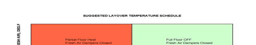
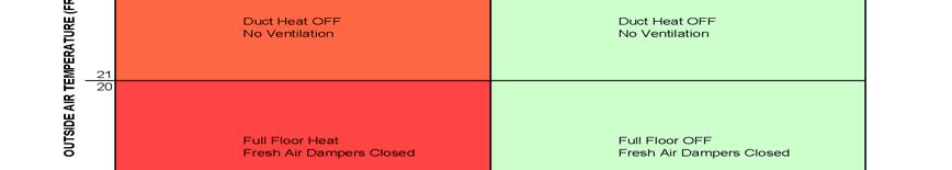
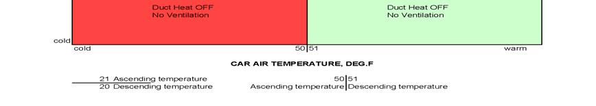
17 HVAC System Figure 10-2: Suggested Temperature Control Schedule Sample * End of Chapter 10 *
B. Unit construction shall comply with ASHRAE 15 Safety Code, NEC, and ASME applicable codes (U.S.A. codes).
.") Guide Specifications PART 1 GENERAL 1.01 SYSTEM DESCRIPTION Microprocessor controlled, air-cooled liquid chiller utilizing scroll compressors, low sound fans, hydronic pump system and optional fluid storage
Guide Specifications PART 1 GENERAL 1.01 SYSTEM DESCRIPTION Microprocessor controlled, air-cooled liquid chiller utilizing scroll compressors, low sound fans, hydronic pump system and optional fluid storage
Internal ridged board 1" x 1.5 foil face installation shall be installed on roof, walls and base of casing.
 A-D WITH MPU SPECIFICATION WRITTEN SPECIFICATION Description A Modular Packaged Heating, Cooling and ventilating unit(s), as indicated on the drawings shall be furnished. Direct Fired Gas Unit(s) shall
Chapter 17 Emergency Equipment
 Standardized Technical Specification Bi-Level Passenger Rail Cars for Intercity Corridor Service Chapter 17 Emergency Equipment Revision G Table of Contents 17-1 Table of Contents 17.0 Emergency Equipment...
Union County Vocational - Technical Schools Scotch Plains, New Jersey
 SECTION 230593 - TESTING, ADJUSTING, AND BALANCING FOR HVAC PART 1 - GENERAL 1.1 SUMMARY A. Section Includes: 1. Balancing Air Systems: a. Constant-volume air systems. b. Variable-air-volume systems. 2.
TECHNICAL GUIDE DESCRIPTION SPLIT-SYSTEM AIR-COOLED CONDENSING UNITS MODELS: HF-07 FEATURES B-0703
 TECHNICAL GUIDE SPLIT-SYSTEM AIR-COOLED CONDENSING UNITS MODELS: HF-07 DESCRIPTION These Sunline 2000 units are completely assembled, piped and wired at the factory to provide one-piece shipment and rigging.
Direct Fired Heater Model AD Specification
 Direct Fired Heater Model AD Specification Description A Direct-fired gas heating and ventilating unit(s), as indicated on the drawings shall be furnished. Unit(s) shall be tested in accordance with ANSI
SECTION PACKAGED ROOFTOP AIR CONDITIONING UNITS
 SECTION 15732 - PACKAGED ROOFTOP AIR CONDITIONING UNITS PART 1 - GENERAL 1.1 SECTION INCLUDES A. Package roof top unit. B. Heat exchanger. C. Refrigeration components. D. Unit operating controls. E. Roof
SECTION SEQUENCE OF OPERATIONS FOR HVAC CONTROLS
 SECTION 23 09 93 SEQUENCE OF OPERATIONS FOR HVAC CONTROLS PART 1 - GENERAL 1.1 SUMMARY A. This Section includes control sequences for HVAC systems, subsystems, and equipment. B. See Division 23 Section
RetroAire Model Number: 9,000 to 36,000 Btuh (2.6 to 10.5 kw)
") Indoor Single Package Vertical, Air-Cooled Heat Pump Unit RetroAire Model Number: Capacity Range: VPRH 9,000 to 36,000 Btuh (2.6 to 10.5 kw) Part 1 General 1.01 UNIT DESCRIPTION A. Indoor, single package
Indoor Single Package Vertical, Air-Cooled Heat Pump Unit RetroAire Model Number: Capacity Range: VPRH 9,000 to 36,000 Btuh (2.6 to 10.5 kw) Part 1 General 1.01 UNIT DESCRIPTION A. Indoor, single package
C. ASME Compliance: Fabricate and label water chiller heat exchangers to comply with ASME Boiler and Pressure Vessel Code: Section VIII, Division 1.
 SECTION 236426 - ROTARY-SCREW WATER CHILLERS PART 1 - GENERAL 1.1 SUMMARY A. This Section includes packaged, water cooled or air cooled as scheduled, electric-motor-driven, rotary-screw water chillers
CAS. Product Specifications. COMMERCIAL SPLIT SYSTEMS CONDENSING UNITS R 410A, 6 to 12.5 TONS BUILT TO LAST, EASY TO INSTALL AND SERVICE
 COMMERCIAL SPLIT SYSTEMS CONDENSING UNITS R 410A, 6 to 12.5 TONS BUILT TO LAST, EASY TO INSTALL AND SERVICE CAS Product Specifications Single stage cooling capacity control on all models with Micro channel
Direct Gas-Fired Make-Up Air
 Direct Gas-Fired Make-Up Air Model TSU Heavy Duty, High Airflow Applications Manufacturing and Industrial Facilities Up to 64,000 cfm August 2012 Products Model TSU Direct Gas-Fired Make-Up Air Unit The
INTRODUCTION. Special Applications of Package Air Conditioners. Instant Cooling Requirement in Wedding Ceremonies
 Pakistan s Largest Manufacturers of Air-Conditioners PACKAGE TYPE UNIT FOR MOBILE APPLICATIONS Provides Turnkey Projects Conceptual Planning to Commissioning of HVACR Projects THE LARGEST MANUFACTURER
SPECIFICATION GUIDE FLEXAIR. Possibility to add auxiliary heaters: Gas, Electrical Heater, Hot Water Coil Possibility to add Heat Recovery Module
 SPECIFICATION GUIDE FLEXAIR Air-cooled packaged Rooftop unit Cooling only or Heat Pump Nominal cooling capacity: 85 to 234 kw Nominal heating capacity: 83 to 226 kw Possibility to add auxiliary heaters:
SECTION SEQUENCE OF OPERATIONS FOR HVAC CONTROLS
 PART 1 - GENERAL SECTION 23 09 93 SEQUENCE OF OPERATIONS FOR HVAC CONTROLS 1.1 SUMMARY A. This Section includes control sequences for HVAC systems, subsystems, and other equipment. B. See Division 23 Section
Modular Supply Make-Up Air Unit
 Modular Supply Make-Up Air Unit Model MSX Flexible Design Factory Assembled Heating Options Hot Water Steam Electric Cooling Options Evaporative Direct Expansion Chilled Water November 2009 Product Features
TECAM S.A. harmony. 5PZA Direct Expansion. Air Conditioning Equipment Manufacturer. R-410A PRECISION UNIT 2 Ton 6 Ton / 60 Hz. Tecnología Ambiental
 TECAM S.A. Tecnología Ambiental R-410A PRECISION UNIT 2 Ton 6 Ton / 60 Hz harmony 5PZA Direct Expansion Registration No.: SC 4696-1 Registration No.: CO-SC 4696-1 Air Conditioning Equipment Manufacturer
Advance Release September 2009
 Vertical Air Cooled DSV Series R 410A Model DSV096 DSV120 DSV144 DSV180 Nominal Cooling (Tons) 8 10 12 15 Refrigerant R 410A R 410A R 410A R 410A Cooling Performance Gross Cooling Capacity(Btu/h) 95,000*
HVAC REPAIR/REPLACEMENT 07/18/12 SECTION HVAC - MAJOR EQUIPMENT
 SECTION 15300 - HVAC - MAJOR EQUIPMENT PART 1 - GENERAL 1.1 MECHANICAL GENERAL A. Section 15010 is applicable. PART 2 - PRODUCTS 2.1 FANS A. General: 1. All fans shall bear the AMCA Certified Performance
Call us today! (800)
") PA-ACCTR-200 Call us today! (800)341-4297 The 200-Ton portable chiller package features a Trane RTAC chiller unit. Trane leads the industry in providing some of the most reliable, efficient and quiet chiller
PA-ACCTR-200 Call us today! (800)341-4297 The 200-Ton portable chiller package features a Trane RTAC chiller unit. Trane leads the industry in providing some of the most reliable, efficient and quiet chiller
AIR DISTRIBUTION. C. Section Building Automation and Control System Guidelines. D. Section Fire Alarm System & Detection Systems
 233100 AIR DISTRIBUTION PART 1: GENERAL 1.01 RELATED SECTIONS A. Section 230700 HVAC Insulation B. Section 237300 Air Handling C. Section 230900 Building Automation and Control System Guidelines D. Section
1.03 RELATED SECTIONS: The following sections contain requirements that relate to this section.
 SECTION 15855 GAS FURNACE/DX COOLING UNIT PART 1 - GENERAL 1.01 RELATED DOCUMENTS A. Drawings and general provisions of contract including General and Supplementary Conditions of Division 1 of Specification
TECHNICAL GUIDE. Description SPLIT-SYSTEM AIR-COOLED CONDENSING UNITS YD360, 480 & THRU 50 NOMINAL TONS YTG-B-0811
 Description These units are completely assembled, piped and wired at the factory to provide one-piece shipment and rigging. Each unit is pressurized with a holding charge of Refrigerant R-410A for storage
Hood Depot Internatioonal, Inc., Phone S. Powerline Road, Deerfield Beach, FL
 The Kitchen Cool by Hood Depot is a conditioned make up air unit design with flexibility, form and function kept in mind. Our unit offers a variety of configurations that allow the customer to customize
ENVIRONMENTAL CONTROL UNIT (ECU) PART NUMBER OPERATIONS AND MAINTENANCE MANUAL
 PART NUMBER OPERATIONS AND MAINTENANCE MANUAL") ENVIRONMENTAL CONTROL UNIT (ECU) PART NUMBER 2001829 OPERATIONS AND MAINTENANCE MANUAL Prepared by: 860 Douglas Way PO Box 530 Natural Bridge Station, VA 24579 1.0 SCOPE: This Operations and Maintenance
ENVIRONMENTAL CONTROL UNIT (ECU) PART NUMBER 2001829 OPERATIONS AND MAINTENANCE MANUAL Prepared by: 860 Douglas Way PO Box 530 Natural Bridge Station, VA 24579 1.0 SCOPE: This Operations and Maintenance
Industrial Space Heating Direct Gas-Fired Heating. Greenheat 50/50 Recirculation
 Industrial Space Heating Direct Gas-Fired Heating Greenheat 00% Outdoor Air Greenheat 50/50 Recirculation 80/0 Recirculation March 008 Product Overview Industrial Space Heating Greenheck s space heating
100 TON AIR-COOLED SCROLL PACKAGED. Call us today! (800) SPECIFICATIONS GENERAL DIMENSIONS ELECTRICAL DATA ADDITIONAL INFORMATION
 SPECIFICATIONS GENERAL DIMENSIONS ELECTRICAL DATA ADDITIONAL INFORMATION") 100 TON AIR-COOLED SCROLL PACKAGED SPECIFICATIONS Call us today! (800)341-4297 Trane Portable Packaged Air Conditioner units contain the best compressor technology available, in order to achieve the highest
100 TON AIR-COOLED SCROLL PACKAGED SPECIFICATIONS Call us today! (800)341-4297 Trane Portable Packaged Air Conditioner units contain the best compressor technology available, in order to achieve the highest
VERTICAL STACK INNKEEPER GUIDE SPECIFICATION CGC Hybrid Heat Pump System
 VERTICAL STACK INNKEEPER GUIDE SPECIFICATION CGC Hybrid Heat Pump System PART 1 SYSTEM DESCRIPTION 1.1 The HVAC system is based on the CGC HYBRID Hydronic Heat Pump System. 1.2 The system will automatically
Call us today! (800)
") 500 TON AIR-COOLED CHILLER PA-ACCTR-500 Call us today! (800)341-4297 The 500-Ton portable chiller package features a Trane RTAC chiller unit. Trane leads the industry in providing some of the most reliable,
500 TON AIR-COOLED CHILLER PA-ACCTR-500 Call us today! (800)341-4297 The 500-Ton portable chiller package features a Trane RTAC chiller unit. Trane leads the industry in providing some of the most reliable,
SECTION WATER-SOURCE UNITARY HEAT PUMPS
 SECTION 23 81 46 WATER-SOURCE UNITARY HEAT PUMPS PART 1 - GENERAL 1.1 RELATED DOCUMENTS A. Drawings and general provisions of Contract, including General and Supplementary Conditions and Division 1 Specification
PACKAGE AIR CONDITIONER
 PACKAGE AIR CONDITIONER FORM NO. ATZ-206 TZAA- HIGH EFFICIENCY SERIES NOMINAL SIZE 10 TON [35.2 kw] 10 TON MODEL [35.2 kw] This product is shipped with a nitrogen holding charge that must be vented prior
KINGS COUNTY JAIL EXPANSION PHASE III COUNTY OF KINGS SECTION
 SECTION 237433, PART 1 - GENERAL 1.1 RELATED DOCUMENTS A. Drawings and general provisions of the Contract, including General and Supplementary Conditions and Division 01 Specification Sections, apply to
FT900BD FLIGHT-TYPE DISHWASHER
 Item # Quantity C.S.I. Section 11400 FT900BD FLIGHT-TYPE DISHWASHER STANDARD FEATURES Opti-RinSe system Water usage 120 gph @ 20 psi Microprocessor controls Low temperature alert Blower dryer with 2 H.P.
OPERATIONS AND MAINTENANCE MANUAL FOR THE 8-TON TURF CART ENVIRONMENTAL CONTROL UNIT (ECU) PART NUMBER
 PART NUMBER") OPERATIONS AND MAINTENANCE MANUAL FOR THE 8-TON TURF CART ENVIRONMENTAL CONTROL UNIT (ECU) PART NUMBER 2001927 Prepared by: 860 Douglas Way PO Box 530 Natural Bridge Station, VA 24579 1 1.0 SCOPE: This
OPERATIONS AND MAINTENANCE MANUAL FOR THE 8-TON TURF CART ENVIRONMENTAL CONTROL UNIT (ECU) PART NUMBER 2001927 Prepared by: 860 Douglas Way PO Box 530 Natural Bridge Station, VA 24579 1 1.0 SCOPE: This
Brown University Revised August 3, 2012 Facilities Design & Construction Standards SECTION AIR HANDLING UNITS
 SECTION 23 70 00 AIR HANDLING UNITS PART 1. GENERAL 1.1 Section includes air-handling units to 15,000 cfm and accessories. 1.2 Related Sections 1 : A. Division 01 - Brown University Standard for Narragansett
Call us today! (800)
") 150 TON AIR-COOLED CHILLER PA-ACCTR-150 Call us today! (800)341-4297 The 150-Ton portable chiller package features a Trane RTAC chiller unit. Trane leads the industry in providing some of the most reliable,
150 TON AIR-COOLED CHILLER PA-ACCTR-150 Call us today! (800)341-4297 The 150-Ton portable chiller package features a Trane RTAC chiller unit. Trane leads the industry in providing some of the most reliable,
SECTION PACKAGED, OUTDOOR, CENTRAL-STATION AIR-HANDLING UNITS
 SECTION 237413 - PACKAGED, OUTDOOR, CENTRAL-STATION AIR-HANDLING UNITS PART 1 - GENERAL 1.1 SUMMARY A. This Section includes packaged, outdoor, central-station air-handling units (rooftop units) with the
RGE 13 A T - 1 A
 PRODUCT SPECIFICATIONS PACKAGED GAS / ELECTRIC 3GEP / RGE3 Rooftop Units 60HZ Bulletin No. 2063 December 202 Supersedes October 202 MODEL NUMBER IDENTIFICATION -PHASE MODELS SEER - 3.00 (3GEP Shown) AFUE
2 shp 13 lc 1 36 t - 1 a
 HEAT PUMPs 2SHP3 PRODUCT SPECIFICATIONS Dry Charge Split System - 60 HZ Bulletin No. 20645 July 203 Supersedes June 202 3 to 5 Tons MODEL NUMBER IDENTIFICATION 2 shp 3 lc 36 t - a Refrigerant Type 2 =
A. Section includes split-system air-conditioning units consisting of separate evaporator-fan and compressor-condenser components.
 Page 238126-1 SECTION 238126 - This Section includes requirements for the LEED Rating System. However, equipment specified in this Section may not qualify for LEED Rating System prerequisites and credits.
User s Information and Installation Instructions
 Outdoor Air Conditioner User s Information and Installation Instructions 10 SEER Standard Efficiency Split System These units have been designed and tested for capacity and efficiency in accordance with
Submittal Data Performance Data Electrical Data
 ERMS Series Submittal Data Submittal Data Unit Designation: Job name: Architect: Engineer: Contractor: Performance Data Revision: 07/01/11 Cooling Capacity: EER: Heating Capacity: COP: Ambient Air Temp:
SECTION SPLIT-SYSTEM AIR-CONDITIONERS
 SECTION 23 81 26 SPLIT-SYSTEM AIR-CONDITIONERS PART 1 - GENERAL 1.1 SUMMARY A. Section includes split-system air-conditioning units consisting of separate evaporator-fan and compressor-condenser components.
PACKAGED AIR COOLED Product Data Catalog
 PACKAGED AIR COOLED Product Data Catalog MODELS ASP-10A ASP-15A ASP-20A ASP-00P ASP-00F ASP-00G A MEMBER OF MARDUK HOLDING COMPANY, LLC The Leader in Modular Chillers ETL and CSA Approved CHILLER MODULES
High Plume Blowers Suggested Specification Section (Master Format 1996) Suggested Specification Section (Master Format 2004)
 Suggested Specification Section (Master Format 2004)") High Plume Blowers Suggested Specification Section 15500 (Master Format 1996) Suggested Specification Section 23 38 16 (Master Format 2004) PART 1 GENERAL 1.01 WORK INCLUDED High Plume Laboratory Exhaust
High Plume Blowers Suggested Specification Section 15500 (Master Format 1996) Suggested Specification Section 23 38 16 (Master Format 2004) PART 1 GENERAL 1.01 WORK INCLUDED High Plume Laboratory Exhaust
SECTION CONVECTION HEATING AND COOLING UNITS
 PART 1 GENERAL 1.01 SECTION INCLUDES A. Baseboard radiation. B. Finned tube radiation. C. Convectors. D. Unit heaters. E. Cabinet unit heaters. F. Fan-coil units. G. Unit ventilators. H. Blower-coil units.
FT900SDBD DUAL RINSE FLIGHT-TYPE DISHWASHER
 Item # Quantity C.S.I. Section 11400 FT900SDBD DUAL RINSE FLIGHT-TYPE DISHWASHER STANDARD FEATURES Opti-RinSe system with dual rinse Water usage 72 gph @ 20 psi Microprocessor controls Low temperature
Nominal Capacity 024 = 7 kw (2 tons) 036 = 10.5 kw (3 tons) 048 = 14 kw (4 tons) 060 = 17.5 kw (5 tons)
 036 = 10.5 kw (3 tons) 048 = 14 kw (4 tons) 060 = 17.5 kw (5 tons)") ENGINEERING DATA HEAT PUMP OUTDOOR UNITS HP40 50HZ Capacity 6.2 to 16.3 (21 200 to 55 500 Btuh) Heating Capacity 6.4 to 16.1 (21 800 to 55 500 Btuh) Bulletin No. 490088 October 2004 Supersedes August 1999
ENGINEERING DATA HEAT PUMP OUTDOOR UNITS HP40 50HZ Capacity 6.2 to 16.3 (21 200 to 55 500 Btuh) Heating Capacity 6.4 to 16.1 (21 800 to 55 500 Btuh) Bulletin No. 490088 October 2004 Supersedes August 1999
Stanford University Facilities Design Guidelines SECTION DECENTRALIZED UNITARY HVAC EQUIPMENT
 SECTION 23 81 00 DECENTRALIZED UNITARY HVAC EQUIPMENT PART 1 - GENERAL 1.1 SUMMARY A. Section includes packaged roof top unit, unit controls, remote panel, roof mounting curb and base, maintenance service,
DSV Model Air Cooled Self Contained Indoor Packaged Units 3-5 Tons Preliminary Application Data
 DSV Model Air Cooled Self Contained Indoor Packaged Units 3-5 Tons Preliminary Application Data July 28, 2008 Page 1 1 of 3 PROJECT: TAG: Gross Cooling Capacity [Btuh]: 37,800* Design CFM: 1,200 Seasonal
SECTION PACKAGED COMPRESSOR AND CONDENSER UNITS
 SECTION 236200 - PACKAGED COMPRESSOR AND CONDENSER UNITS PART 1 - GENERAL 1.1 RELATED DOCUMENTS A. Drawings and general provisions of the Contract, including General and Supplementary Conditions apply
JOB NAME: LOCATION: PURCHASER: ENGINEER: SUBMITTED TO: FOR: REFERENCE [ ] APPROVAL [ ] CONSTRUCTION [ ] SUBMITTED BY: DATE:
![JOB NAME: LOCATION: PURCHASER: ENGINEER: SUBMITTED TO: FOR: REFERENCE [ ] APPROVAL [ ] CONSTRUCTION [ ] SUBMITTED BY: DATE:](/thumbs/95/125855728.jpg "JOB NAME: LOCATION: PURCHASER: ENGINEER: SUBMITTED TO: FOR: REFERENCE [ ] APPROVAL [ ] CONSTRUCTION [ ] SUBMITTED BY: DATE:") T2HA, T3HA, and T4HA with CAHB Systems Limited Range Multi-Zone Heat Pumps Rev. 1.1 [07/07] JOB NAME: LOCATION: PURCHASER: ENGINEER: SUBMITTED TO: FOR: ERENCE [ ] APPROVAL [ ] CONSTRUCTION [ ] SUBMITTED
T2HA, T3HA, and T4HA with CAHB Systems Limited Range Multi-Zone Heat Pumps Rev. 1.1 [07/07] JOB NAME: LOCATION: PURCHASER: ENGINEER: SUBMITTED TO: FOR: ERENCE [ ] APPROVAL [ ] CONSTRUCTION [ ] SUBMITTED
VariCool VAV Engineering Guide
 Engineering Guide Effective September 2017 Water-Cooled and Chilled Water, Variable Air Volume Contents Product Features... 3 UNIT FEATURES... 3 Product Features... 4 Marvel Plus Microprocessor Control
Submittal Data PERFORMANCE DATA CERTIFIED DIMENSION PRINTS CERTIFIED ROOF CURB DIMENSION PRINTS SERVICE OPTION DIMENSION PRINTS
 Single Package Rooftop Gas Heating/Electric Cooling Unit Two Stage Cooling Capacity Control with Puronr (R---410A) Refrigerant Sizes: 17, 20, 24, 28, 30 Submittal Data PERFORMANCE DATA CERTIFIED DIMENSION
Product Data. Features/Benefits. OMNIZONE 50BV Remote Air-Cooled and Water-Cooled Indoor Self-Contained Systems and Water Source Heat Pumps
 Product Data OMNIZONE 50BV020-064 Remote Air-Cooled and Water-Cooled Indoor Self-Contained Systems and Water Source Heat Pumps 18 to 60 Nominal Tons omnizonebwlogo 50BVC,E,J,K,Q020-034 SINGLE PIECE OMNIZONE
1.1 This section applies to air handling units for HVAC Systems.
 AIR HANDLING UNITS GENERAL INFORMATION 1.1 This section applies to air handling units for HVAC Systems. DESIGN REQUIREMENTS 2.1 Design Criteria a. The decision to use modular central station air handling
3 to 5 Tons. AIR CONDITIONERS 2scu13. Dry Charge Split System - 60 HZ PRODUCT SPECIFICATIONS. 2 scu 13 lc 1 36 t - 1 a MODEL NUMBER IDENTIFICATION
 AIR CONDITIONERS 2scu3 PRODUCT SPECIFICATIONS Dry Charge Split System - 60 HZ Bulletin No. 20644 May 204 Supersedes September 203 3 to 5 Tons MODEL NUMBER IDENTIFICATION 2 scu 3 lc 36 t - a Refrigerant
Chapter 11. Lighting System
 Standardized Technical Specification PRIIA 5 Next-Generation Equipment Committee Bi-Level Passenger Rail Cars Chapter 11 Lighting System Table of Contents 11-1 Table of Contents 11.0 Lighting System...
City of Duluth Festival Center 04/25
 SECTION 230593 - TESTING, ADJUSTING, AND BALANCING FOR HVAC PART 1 - GENERAL 1.1 RELATED DOCUMENTS A. Drawings and general provisions of the Contract, including General and Supplementary Conditions and
Series PACKAGED ROOFTOP UNITS, HEAT PUMPS AND OUTDOOR AIR HANDLING UNITS. Features:
 RZ PACKAGED ROOFTOP UNITS, HEAT PUMPS AND OUTDOOR AIR HANDLING UNITS Features: Air-cooled condenser, water-cooled condenser, or evaporative-cooled condenser packaged rooftop units from 55-240 tons Water-source
TECHNICAL GUIDE SPLIT-SYSTEM AIR-COOLED EVAPORATOR BLOWER 25, 30, 40 & 50 TON LA300, LB360, 480 & 600 (50 Hz) PROVEN PERFORMANCE GENERAL FEATURING
 PROVEN PERFORMANCE GENERAL FEATURING") TECHNICAL GUIDE SPLIT-SYSTEM AIR-COOLED EVAPORATOR BLOWER 25, 30, 40 & 50 TON LA300, LB360, 480 & 600 (50 Hz) PROVEN PERFORMANCE GENERAL The LA/LB line is a flexible performer. LA300, LB360 & 480 can be
TECHNICAL GUIDE SPLIT-SYSTEM AIR-COOLED EVAPORATOR BLOWER 25, 30, 40 & 50 TON LA300, LB360, 480 & 600 (50 Hz) PROVEN PERFORMANCE GENERAL The LA/LB line is a flexible performer. LA300, LB360 & 480 can be
Indirect Gas-Fired Make-Up Air
 Indirect Gas-Fired Make-Up Air Model IG 800 to 7,000 cfm Up to 400,000 Btu/hr Multiple Furnace Control Options Optional Evaporative Cooling May 20041 Product Features Model IG Indirect Gas-Fired Make-Up
Submittal Data PERFORMANCE DATA CERTIFIED DIMENSION PRINTS CERTIFIED ROOF CURB DIMENSION PRINTS SERVICE OPTION DIMENSION PRINTS
 AutoZone R Model Single Package Rooftop Gas Heating/Electric Cooling Unit Size 07 with Puronr (R---410A) Refrigerant Submittal Data PERFORMANCE DATA CERTIFIED DIMENSION PRINTS CERTIFIED ROOF CURB DIMENSION
NFZP Variable Refrigerant Flow Guide Specification
 PART 1 - GENERAL 1.01 SECTION INCLUDES SECTION 23 81 29 VARIABLE REFRIGERANT FLOW HVAC SYSTEM A. (VRF) HVAC system includes: 1. Outdoor/Condensing unit(s): a. Size Range: 14 Tons Nominal b. YANMAR VRF
SECTION ROTARY-SCREW WATER CHILLERS
 PART 1 GENERAL 1.01 SECTION INCLUDES A. Factory-assembled packaged chiller. B. Charge of refrigerant and oil. C. Controls and control connections. D. Chilled water connections. E. Electrical power connections.
FEATURES AND BENEFITS
 FEATURES AND BENEFITS Product Features and Benefits Full Product Line Offering Feature All models are 80% thermally efficient Blower performance up to 3.0 W.C. DX or chilled water section with factory
KG 092 SHOWN READ ALL INSTRUCTIONS IN THIS MANUAL AND RETAIN FOR FUTURE REFERENCE WARNING
 See unit nameplate for manufacturer and address. 507350-03 3/2016 Supersedes 9/2015 KG 024, 030, 036, 048, 060, 072, 074, 090 (2, 2-1/2, 3, 4, 5, 6 and 7-1/2 Tons) KG 092, 102, 120, 150 (7-1/2, 8 1/2,
AIR HANDLERS. Central Station (CS3) Roof Mounted (RT) (Modular AL Frame AHU)
 Roof Mounted (RT) (Modular AL Frame AHU)") AIR HANDLERS Central Station (CS3) (Modular AL Frame AHU) Roof Mounted (RT) CONTENTS 1. CS3 Modular Aluminium Frame AHU : Unit Types 2. Casing Structure 3. Blowers and Drives 4. Coils 5. Options and Accessory
AIR HANDLERS Central Station (CS3) (Modular AL Frame AHU) Roof Mounted (RT) CONTENTS 1. CS3 Modular Aluminium Frame AHU : Unit Types 2. Casing Structure 3. Blowers and Drives 4. Coils 5. Options and Accessory
SKYPAK II, 3 Ton Series, gives you a
 SKYPAK II 3 ton Heating And Cooling self-contained Package SKYPAK II, 3 Ton Series, gives you a complete air-conditioning and heating system as an all in one package unit. Designed for convenient through-the-wall
maintenance should only be performed by a trained, qualified person. Consumer service is recommended only for filter replacement.
 AHF / AHK SERIES AIR HANDLING UNITS INSTALLATION GUIDE GENERAL The AHF / AHK series is designed for horizontal recessed installations in a furred down area, above a suspended ceiling or recessed in the
Installation Instructions
 Installation Instructions PAM3 SERIES PACKAGE AIR CONDITIONERS TABLE OF CONTENTS SAFETY LABELING AND SIGNAL WORDS... 2 UNIT DIMENSIONS... 3 SAFE INSTALLATION REQUIREMENTS... 3 LOCATING THE UNIT... 3 CLEARANCES...
Rooftop Ventilator. Models RV and RVE. with Packaged Cooling & Heating
 Rooftop Ventilator with Packaged Cooling & Heating Models RV and RVE Institutional Commercial Industrial 800-1,500 cfm.0 in. wg External Static Pressure Indirect Gas, Hot Water, Electric Heating Packaged
DENVER PUBLIC SCHOOLS DESIGN AND CONSTRUCTION STANDARDS This Standard is for guidance only. SECTION REFRIGERATION
 PART 0 A/E INSTRUCTIONS 0.01 DESIGN REQUIREMENTS A. General: 1. Design and specify refrigeration systems and equipment in accordance with "Energy Conservation Standards" stipulated in Section 15010, Basic
ENGINEERING GUIDE. Water-Cooled Self-Contained Units C-Series, Vertical
 ENGINEERING GUIDE Water-Cooled Self-Contained Units C-Series, Vertical TABLE OF CONTENTS Introduction...2 Product Overview...3 Nomenclature...4 General Data...5 Cooling Performance Data....6 Evaporator
INSTALLATION INSTRUCTIONS FMB/FMC SERIES MULTI-POSITION AIR HANDLER
 INSTALLATION INSTRUCTIONS FMB/FMC SERIES MULTI-POSITION AIR HANDLER IMPORTANT MASSAGE TO INSTALLER: "The United States Environmental Protection Agency ("EPA") has issued various regulations regarding the
GUIDE SPECIFICATIONS AQUARIUS ii
 Catalog (AP Technical Data Sheet) GUIDE SPECIFICATIONS AQUARIUS ii AP Series Two Stage R-410A GENERAL Units shall be performance certified to ISO standard 13256-1 for Water Loop Heat Pump, Ground Water
T-Series Air Conditioner T20 Model
 INSTRUCTION MANUAL T-Series Air Conditioner T20 Model Protecting Electronics. Exceeding Expectations. McLean Cooling Technology 11611 Business Park Blvd N Champlin, MN 55316 USA Tel 763-323-8200 Fax 763-576-3200
PAJ3. Product Specifications
 13 SEER, R 410A PACKAGE AIR CONDITIONER FOR MANUFACTURED HOUSING, RESIDENTIAL, AND LIGHT COMMERCIAL APPLICATIONS 2 5 TONS Single Phase, 208/230 V, 60 Hz BUILT TO LAST, EASY TO INSTALL AND SERVICE Compact,
Guide Specifications for InRow Direct Expansion
 Guide Specifications Guide Specifications for InRow Direct Expansion THIS GUIDE SPECIFICATION IS WRITTEN IN ACCORDANCE WITH THE CONSTRUCTION SPECIFICATIONS INSTITUTE (CSI) MASTERFORMAT. THIS SECTION MUST
Series. Packaged Rooftop Units, heat pumps and Outdoor air handling Units. Features:
 RL Packaged Rooftop Units, heat pumps and Outdoor air handling Units Features: Air-cooled condenser, water-cooled condenser, or patented AAON evaporative-cooled condenser, with capacities from 45-240 tons
.2 Section Waste Management and Disposal.
 Issued 2005/06/01 Section 15624 Packaged Rotary Screw Water Chillers Page 1 of 5 PART 1 General 1.1 RELATED SECTIONS.1 Section 01330 Submittal Procedures..2 Section 01355 Waste Management and Disposal..3
60 TON AIR-COOLED CHILLER. Call us today! (800) PA-ACCTR-60 GENERAL DIMENSIONS ELECTRICAL DATA 60 TON AIR-COOLED CHILLER FEATURES
 PA-ACCTR-60 GENERAL DIMENSIONS ELECTRICAL DATA 60 TON AIR-COOLED CHILLER FEATURES") 60 TON AIR-COOLED CHILLER PA-ACCTR-60 Call us today! (800)341-4297 The 60-Ton portable chiller package features a Trane CGAM chiller unit. Trane leads the industry in providing some of the most reliable,
60 TON AIR-COOLED CHILLER PA-ACCTR-60 Call us today! (800)341-4297 The 60-Ton portable chiller package features a Trane CGAM chiller unit. Trane leads the industry in providing some of the most reliable,
The ultimate fresh air solution.
 Fresh Access The ultimate fresh air solution. Introducing Fresh Access TM. Expertly designed, our innovative energy recovery ventilator (ERV) unit, split dedicated outside air system (DOAS), and packaged
DOCUMENT TABLE OF CONTENTS
 DOCUMENT 00003 June 16, 2005 TABLE OF CONTENTS DOCUMENT NO. INTRODUCTORY INFORMATION DOCUMENT 00003 TABLE OF CONTENTS DIVISION 1 GENERAL REQUIREMENTS SECTION 01011 SECTION 01025 SSP21.1-1 SECTION 01026
UP to 14.5 SEER, PACKAGE AIR CONDITIONER UNIT, 2 to 5 TONS 208/230 Volt, 1 phase, 60 Hz REFRIGERATION CIRCUIT
 SOUND REFRIGERANT ENVIRONMENTALLY PAJ4 Product Specifications UP to 14.5 SEER, PACKAGE AIR CONDITIONER UNIT, 2 to 5 TONS 208/230 Volt, 1 phase, 60 Hz REFRIGERATION CIRCUIT Environmentally sound R-410A
SECTION TESTING, ADJUSTING, AND BALANCING FOR HVAC INTRODUCTORY INFORMATION
 SECTION 15990 TESTING, ADJUSTING, AND BALANCING FOR HVAC INTRODUCTORY INFORMATION The purpose of this guide specification is to assist the Specifier in correctly specifying Mechanical System Testing Adjusting
ISERIES VERTICAL AHU ENGINEERING SPECIFICATIONS
 ISERIES VERTICAL AHU ENGINEERING SPECIFICATIONS BULLETIN 20-131.001 Page 1 Copyright 2017 Unico Inc. TABLE OF CONTENTS APPLICATIONS... 3 CABINET CONSTRUCTION... 3 FEATURES AND CONTROLS... 3 DIMENSIONAL
AIR COOLED PACKAGED CHILLER
 AIR COOLED PACKAGED CHILLER UNIC sal is equipped to produce a wide range of COOLER Air conditioning and Refrigeration units, conforming to the international standards and works continually to improve its
SPLIT-SYSTEM HEAT PUMPS 50 AND 60 HZ DESCRIPTION
 SPLIT-SYSTEM HEAT PUMPS 50 AND 60 HZ E3FB090/E1FB120/F3EH090 & 120 7-1/2 & 10 NOMINAL TONS (60 HZ) 7 & 9 NOMINAL TONS (50 HZ) (9.0-9.2 EER) 208/230/460 VOLT ONLY 208/230 VOLT ONLY DESCRIPTION YORK has
13 GEP A L P - 1 A
 PRODUCT SPECIFICATIONS PACKAGED GAS / ELECTRIC 3GEP MERIT SERIES Residential - R-40A Bulletin No. 20602 December 202 Supersedes October 202 SEER - 3.00 AFUE - 80% 2 to 5 Tons Cooling Capacity - 22,800
VertiCool Aurora Engineering Guide
 Engineering Guide Effective August 2016 Air-Cooled, Water-Cooled and Water Source Heat Pump Contents Product Features... 3 Options... 4 Physical Data...5-6 Air-Cooled Performance Data (a) (b) (c)...7-8
SECTION SPLIT-SYSTEM AIR-CONDITIONERS
 SECTION 238126 PART 1 - GENERAL 1.1 RELATED DOCUMENTS A. Drawings and general provisions of the Contract, including General and Supplementary Conditions and Division 01 Specification Sections, apply to
Installation Guide. Dehumidification. Fresh Air Ventilation. Compact Size. Energy Efficient. RXID-AW90A Whole House Dehumidifier
 RXID-AW90A Whole House Dehumidifier with fresh air ventilation Installation Guide Dehumidification Fresh Air Ventilation Compact Size Energy Efficient The whole house dehumidifier integrates highcapacity
CMA TECHNICAL MANUAL CONDENSING UNITS FOR OUTDOOR INSTALLATION O L S A F RA N
 E S A RE F R E IG RA N T G TECHNICAL MANUAL -FRIEND Y CONDENSING UNITS FOR OUTDOOR INSTALLATION O L CMA C 2 The manufacturer declines all the responsabilities regarding inaccuracies contained in this manual,
INSTALLATION INSTRUCTIONS FMB/FMC SERIES MULTI-POSITION AIR HANDLER
 ASPEN MANUFACTURING 373 ATASCOCITA RD. HUMBLE, TX 77396 TEL (281) 441-6500 FAX (281) 441-6510 > INSTALLATION INSTRUCTIONS FMB/FMC SERIES MULTI-POSITION AIR HANDLER IMPORTANT: "The
Job Name Control Systems Description Date
 Job Name Control Systems Description Date Project Overview The project is a describe the building and its major HVAC systems (e.g. three-story office building, served by a rooftop unit VAV system ). In
RHEEM PACKAGE GAS/ELECTRIC
 INDEX ACCESSORIES... 4-2 SAMPLE SPECIFICATIONS... 4-2 RKNL (3-5 TON) SERIES... 4-6 RKNL-B (6-12.5 TON) SERIES... 4-7 RKNL-B (15-25 TON) SERIES... 4-8 RKNL-C (6-12.5 TON CLEAR CONTROL ) SERIES... 4-9 RKNL-C
CENTRAL, SPLIT SYSTEM REFRIGERATED AIR-CONDITIONING INSPECTION INTERIOR
 Consulting, Resource, Education, Training, and Support Services for Home Inspectors A candle loses no light when it lights another candle. CENTRAL, SPLIT SYSTEM REFRIGERATED AIR-CONDITIONING INSPECTION
SECTION (15767) - UNIT HEATERS
 - UNIT HEATERS") SECTION 23 82 39 (15767) - UNIT HEATERS PART 1 GENERAL 1.01 SUMMARY A. Section includes: 1. Unit Heaters. 2. Cabinet Unit Heaters. 3. Duct Heaters. 4. Baseboard Heaters. B. Related Sections: 1. Section
SECTION 23 82 39 (15767) - UNIT HEATERS PART 1 GENERAL 1.01 SUMMARY A. Section includes: 1. Unit Heaters. 2. Cabinet Unit Heaters. 3. Duct Heaters. 4. Baseboard Heaters. B. Related Sections: 1. Section
T-SERIES Air Conditioner. T20 Model INSTRUCTION MANUAL nvent Rev. C P/N
 T-SERIES Air Conditioner T20 Model INSTRUCTION MANUAL Rev. C P/N 89114993 TABLE OF CONTENTS Warranty and Return Policy... 2 IMPORTANT NOTICE... 2 RECEIVING THE AIR CONDITIONER... 3 HANDLING AND TESTING