Refrigerator BRFB1920SS BRFB1900FBI BRFB1920FBI
|
|
|
- Erik Atkinson
- 6 years ago
- Views:
Transcription

1 Refrigerator BRFB1920SS BRFB1900FBI BRFB1920FBI
2 Table of Contents Symbols and Their Meanings... 3 Product weight... 5 Load bearing capacity of the doors... 5 Climate class... 5 Product Information:... 6 Furniture:... 8 Ventilation:... 8 Combining Kit:... 8 Electrical Connection... 9 Water Connection... 9 TOOL LIST ALTERNATIVES FOR INSTALLATION PREPARATION FOR INSTALLATION Cabin Dimensions Location of the Electrical Wiring Location of the Water System Product Dimensions: Unpacking Removing the Connectors on the Side Wall Removing the Mounting Parts in the Freezer Compartment Removing the FRZ Crisper Removing the FRZ Door Removing the Lower Vent Hole Assembly Removing the Upper Vent Hole Part PRE-INSTALLATION Mounting the Anti-Tip Brackets Alternative anti-tip method: Preparing the Water Hose and the Power Plug INSTALLATION TO THE CABIN Taking the Refrigerator from the Wooden Pallet Placing the refrigerator into the cabin Adjusting the height of the refrigerator in the cabin Adjusting the refrigerator according to the cabin flange Screwing the side brackets Screwing the upper bracket
3 INSTALLING THE CABIN BOTTOM Water connection Attaching the upper vent hole part Attaching the lower vent hole assembly Attaching the kick plate sheet assembly Attaching the decorative parts FURNITURE DOOR PREPARATION Choosing the Door Thickness Removing the Mechanism Covers Removing the 3D Adjusting Mechanism on the Refrigerator Preparing the Fridge Furniture Door Preparing the Freezer Furniture Door Kick Plate Position Adjustment: INSTALLING FURNITURE DOORS Installing the Fridge Furniture Door Installing the Freezer Furniture Door Adjusting the Furniture Door Attaching the covers HINGE ADJUSTMENT Adjusting the hardness of the hinges CHANGING THE DIRECTION OF THE FF DOOR Removing the FF clad door Removing and preparing the Fridge Inner Door Replacing the hinges Installing the FF PU Door Installing the Fridge Furniture Door and adjusting the door INSTALLING THE DUAL CABIN Cabin Dimensions Location of the Electrical Wiring Location of the Water System Removing the Side Brackets Attaching the Fasteners
4 Symbols and Their Meanings Symbols used in the installation manual are as follows. Important information or useful usage tips WARNING: Conditions that may damage the product or its operating functions ATTENTION: Conditions containing serious injury risk Conditions containing electric shock risk Packaging materials of the product have been manufactured from recyclable materials in accordance with our National Environment Regulations. Disposing the packaging materials The package has been designed to protect the product during transport. The packaging materials used for the product do not harm the nature during disposal and they need to be recycled. All plastic packaging materials, bags etc. must be disposed safely and kept out of the reach of children. Please return the packaging to your dealer. WARNING: This installation manual has been prepared to help installation teams. The User Manual provided with the product must also be taken into consideration. You may get seriously injured and your product may get damaged if you ignore the warnings given in this manual. Please read the following carefully. WARNING: R600a Refrigerant This product contains R600a isobutane refrigerant, which is a very eco-friendly natural gas. However, it is also flammable. Please follow the warnings given below: If the product has been transported horizontally, you must wait for 4 hours minimum before plugging it in. The following instructions must be followed during installation: Dimensions of the installation area must be suitable. Dimensions, features and position of the object used to support and fix the product to this area must be suitable. 3
5 Minimum clearances between product parts and surrounding structures must be suitable. Minimum dimensions and proper organisation of ventilation holes must be observed. The product must be connected to the mains power, and corresponding connections of other components must be suitable. The product must be disconnectable from the power supply after installation. The socket or fuse must be accessible to de-energise the product. Extension cables or ungrounded (two-terminal) adapters must not be used. ATTENTION: You must wear gloves and eye protectors when installing the product. You must also take measures against high noise levels when drilling the floor or using a drill. ATTENTION: Make sure that your product is suitable for your local mains. ATTENTION: The product must be installed by a qualified technician according to the installation instructions. WARNING: The product may tip over since it is quite heavy. For this reason, precautions must be taken against tipping over. The doors of the product must be kept closed until it reaches the destination and it must be transported in accordance with the installation instructions. 4
 Climate class Climate range Ambient temperature of the room SN Between +50 o F (10 o C) and +90 o F (32 o C) N Between +60 o F (16 o C) and +90 o F")
6 Product weight BRFB1920SS: lbs ( Kg) Load bearing capacity of the doors Max. load that the Fridge Door can bear: 55 lbs (25 kg) Max. load that the Freezer Door can bear: 22 lbs (10 kg) Climate class Climate range Ambient temperature of the room SN Between +50 o F (10 o C) and +90 o F (32 o C) N Between +60 o F (16 o C) and +90 o F (32 o C) ST Between +60 o F (16 o C) and +110 o F (38 o C) T Between +60 o F (16 o C) and +120 o F (43 o C) This appliance has been designed to be used in certain climate ranges (ambient temperatures). It must not be used out of this range. Climate range of this device is specified on the Barcode Label located inside the appliance. 5
 minimum.")
7 Product Information: As illustrated in the figure below, you can see the Barcode Level at the top right corner of the FRZ Compartment. Installation Place You must follow the instructions below: The floor on which the product will be installed must be capable of bearing 1,200 pounds (544 kg) minimum. Kitchen floor and the bottom of the product must be at the same level. Otherwise, problems may occur with the air suction of the product. There must be no objects preventing the installation of the product at the back and on the side walls of the product's installation place. The power socket must be at the correct place. Dimensions of the furniture where the product will be installed must be in strict conformity with the dimensions given in the manual. Do not install the product with the fridge and the freezer are adherent next to each other. Otherwise, condensation and damage may occur in the product. (Please see "Dual Cabin Installation" for detailed information) Flatness of the floor where the product will be installed must be checked with a Bubble Level Tool. Installation area must not be subjected to direct sunlight and it must be away from heat sources, ovens, radiators etc. 6
8 The ambient temperature must be between 55 F (13 C) and 110 F (43 C). Otherwise, function errors may arise when the product is running. If it is not possible to avoid installing the product near a heat source, the minimum clearances given below must be maintained between the product and the said source: 11/4" (3 cm) from electric hobs or ovens 12" (30 cm) from gas or fuel operated hobs or ovens Please observe the following rules: The power socket or fuse must be easily accessible in case of an emergency; it must not be hidden behind the product. Plug or cable must not touch the back surface of the product. Otherwise, it may get damaged due to the vibration of the product. Do not connect the plugs of other appliances behind this product. If the humidity level is high where the product is used, corrosion may be seen on the outer surface of the product. Keep the installation room dry and well-cleaned to avoid corrosion. To avoid the risk of electric shock: Connect the plug to a grounded 3-pin socket. Do not remove the ground terminal of the plug. Do not use adapters. Do not use extension cables. ATTENTION: Failure to follow these instructions may result in death, fire or electric shock. Connecting the grounding conductor of the equipment to an improper place may lead to electric shock. Please have the grounding checked by a qualified electrician or service technician if you have any doubt about the proper grounding of the product. Installation, repair and other procedures performed by unqualified persons may cause danger. Before installing the appliance, make sure that the voltage, load and circuit current parameters on the data plate are in compliance with the power mains in your house. 7
9 The appliance is provided with a NEMA 5-15 P plug and a 3-pin power cable which is in the UL list and ready to be connected to a 120 V, 60 Hz power supply. Fuse is 15 A. The appliance must be connected to a 3-pin socket. The plug must be installed only by a licensed electrician. If the electrical wiring or the electric power supply of the house needs alteration, the necessary procedures must be performed by a qualified electrician. ATTENTION: Do not install you refrigerator: In open areas In environments where water is dripping In environments where temperature is lower than 55 F (0 C) Furniture: Make sure that the furniture where you will install the appliance has been safely mounted in your kitchen. Your furniture must be connected to the floor and the wall properly and with suitable connections. For the best installation, clearances between the furniture and the product must be in compliance with the values specified in the installation instructions. Side walls must be free of clearances and their surfaces must be flat. Minimum thickness of the side walls must be 5/8" (16 mm). Minimum thickness of the doors to be attached to the product must be ¾" (19 mm). ATTENTION: There is a stainless steel door and stainless kick plate option. Please consult the authorised service. Ventilation: Vent holes where the air enters and exits the unit must not be blocked or obstructed. In addition, you must periodically clean the dust and dirt that accumulate on these holes in time. Combining Kit: There is a combining kit if you wish to use the two refrigerator combined next to each other. If you are going to use them side by side, you will need to demand this kit separately from the authorised service. (Please see "Dual Cabin Installation" for detailed information) 8
10 Electrical Connection Never use an extension cable. The power socket must definitely be grounded and checked by an authorised person. Location of the electrical wiring must comply with the dimensions specified in the manual. ATTENTION: RISK OF ELECTRIC SHOCK Electrical grounding is necessary. This appliance is equipped with a three-pin plug to protect you against possible electric shocks. Do not remove the round grounding terminal from the plug. Do not use two-pin grounding adapters. Do not use extension cables to energise the product. ATTENTION: Do not connect the grounding cable to the gas pipe. Please have the grounding checked by a qualified electrician if you are not sure about the grounding of the product. Do not install a fuse on the neutral line or grounding circuit. WARNING: Please wait for ½-1 hour before energising the product to protect it against possible damages. This way, the refrigerant and the lubricants in the system get balanced. Water Connection Pressure of the mains water must be in compliance with the values specified in the manual. Location of the water system must comply with the dimensions specified in the manual. IMPORTANT INFORMATION: Bypass is recommended for the water filtering system if a reverse osmosis system is used. 9
11 TOOL LIST Tools to be used when installing the product are as follows: Cordless Drill Safety Goggles ½" Wrench Hammer Ladder Ø2.4 Drill bit Ø2.4 Drill bit Box Cutter Safety Gloves Tape measure Star bit T27 Torx Bit T25 Torx Bit T20 Torx Bit ¼" Wrench Flat Bubble Level Tool Wheelbarrow Tape 10
12 ALTERNATIVES FOR INSTALLATION The product can be placed in various ways based on the kitchen design. It must be installed at a place where it is ensured that the door can be opened and closed properly. If the doors cannot be opened 90 degrees at least, you cannot completely open the drawers inside the product. Single cabin placement methods Dual cabin placement methods 11

13 PREPARATION FOR INSTALLATION The instructions below have been prepared according to Built-in type. Built-in: The Appliance and Panels fully seat into the gap, and a material that can be their own box is jammed between the two kitchen cabinets or decorative columns. This is the most common installation scenario. Cabin Dimensions Cabin dimensions below must be checked before starting the installation. 12

14 Location of the Electrical Wiring Location of the electrical wiring must be within the range given below. ATTENTION: Do not use extension cables or two-pin adaptors and do not remove the ground terminal of the grounding cable. ATTENTION: A qualified electrician must ensure that the poles of the socket are connected correctly. Verify that the grounding of the socket is correct. 13

15 Location of the Water System The water connected to the water mains must be potable. Location of the water system must be within the range given below. Water system of the refrigerator must be connected to the water mains system in the house. The user must be able to switch it on/off with the valve when necessary. Objects that might pierce the water hoses or cause them to twist must not be present where the water line is installed. Pressure of the water system must be between psi ( Bar). If the water pressure exceeds 80 psi, install a pressure limiting device or water impact protector to the inlet valve. Never install the product or operate the appliance if it is possible for the water pressure to exceed 120 psi. WARNING: Make sure that there is no water leakage when making the water connections. Otherwise, there will be water on the floor and the furniture will get damaged. You will need a hose with a minimum length of 60" (1.5 meters) and a diameter of ¼" for water connections of the product during installation. A connector that has a thread with an external diameter of ¼ must be used to connect the hose end to the product. Before completing the installation, make sure that water flows and there is no water leakage. 14

16 WARNING: Flatness of the floor where the product will be installed must be checked with a Bubble Level Tool. Uprightness of the furniture flanges must be checked with a Bubble Level Tool. If the flatness and uprightness of the product is not proper, problems may arise with the installation. 15
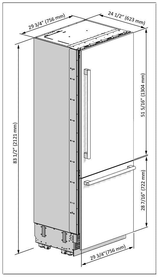
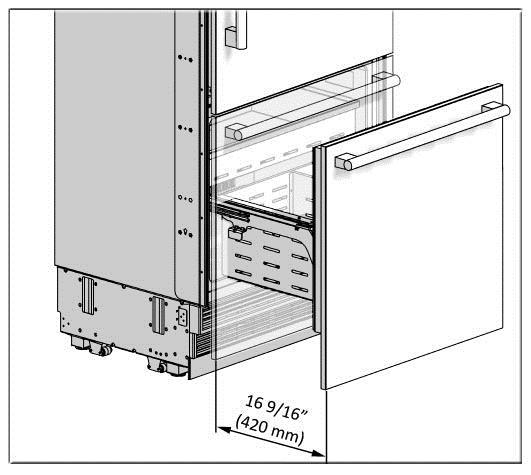
17 Product Dimensions: 16
18 17
19 18
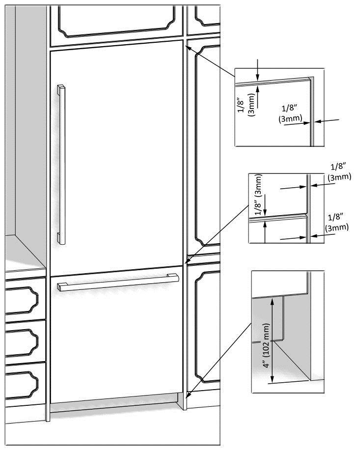
20 Distances between the furniture doors and the kitchen furniture must be 1/8" (3 mm) minimum. 19
 32 7/16\" (824 mm) 32 9/16\" (827 mm) 83 5/8\" (2,124 mm) Max.")
21 Height of the Kitchen Countertop Based on the Min./Max. Height of the Cabin; A B C D Min. 3 3/4" (95 mm) 32 7/16" (824 mm) 32 9/16" (827 mm) 83 5/8" (2,124 mm) Max. 6 1/2" (165 mm) 35 3/16" (894 mm) 35 5/16" (897 mm) 86 3/8" (2,194 mm) 20

22 Unpacking WARNING: At least two persons must carry the refrigerator. Use a box cutter to remove the tapes. Cut the Packaging Board with a Box Cutter through the section illustrated in dotted lines and remove it. 21

23 Remove the Packaging Polystyrene material. ATTENTION: Do not remove the tape of the upper door on the product until the refrigerator is placed into the cabin. Risk of tipping over. 22
24 Removing the Connectors on the Side Wall 1 - Side furniture connection bracket closing parts 2 - Seals between the Furniture, Door and Inner Door for the Fridge (Already attached in products with clad doors) 3 - Seals between the Furniture, Door and Inner Door for the Freezer (Already attached in products with clad doors) 4 - Upper furniture connection bracket closing part 5 - Kick plate sheet metal (Only in products with stainless steel doors) 6 - Freezer Door upper cover 23
25 Removing the Mounting Parts in the Freezer Compartment Open the Freezer Compartment door and remove the Mounting Boxes and documents in the Crisper. Parts in the Mounting Box in Products with Furniture Doors 7 - Anti-Tip Bracket 8 - Dowel 9 - Anti-Tip Bracket Screws 10 - Position adjustment part 11 - Furniture Connection screws 12 - Freezer Furniture Door Adjustment Washer 13 - Fridge Furniture Door Hanger Bracket 14 - Fridge Furniture Door Hanger Part 24
26 15 - Hanger part screws 16 - Hanger bracket part screws limiting pins 29 - Cable Clamp 30 - Screw 31 - Furniture Door Preparation Template Parts in the Mounting Box in Products without Furniture Doors 7 - Anti-Tip Bracket 8 - Dowel 9 - Anti-Tip Bracket Screws 25
27 10 - Position adjustment part 11 - Furniture Connection screws 12 - Freezer Furniture Door Adjustment Washer 13 - Fridge Furniture Door Hanger Bracket 14 - Fridge Furniture Door Hanger Part 15 - Hanger part screws 16 - Hanger bracket part screws limiting pins 18 - Fridge Door side brackets 19 - Fridge Door side bracket covers 20 - Bracket screws (Fridge door connection) 21 - Bracket screws (Furniture connection) 22 - Fridge/Freezer Door middle brackets 23 - Bracket screws (Furniture connection) 24 - Bracket screws (Fridge/Freezer door connection) 25 - Freezer Door upper brackets 26 - Bracket screws (Furniture connection) 27 - Bracket screws (Freezer door connection) 28 - Cradle screws 29 - Cable Clamp 30 - Screw 31 - Furniture Door Preparation Template 26


28 Removing the FRZ Crisper Remove it manually with 4 knurled screws. Remove the Lower Crisper. 27

29 Removing the FRZ Door Remove 2 screws which are near the front section and connect the FRZ Door and the rail. 28
30 Pull the door frontward to free it from the tabs at the back and remove it. Removing the Lower Vent Hole Assembly Remove the 2 screws to take out the Lower Vent Hole Assembly. 29

31 Removing the Upper Vent Hole Part Remove the 2 screws to take out the Upper Vent Hole Part. 30
32 PRE-INSTALLATION Continue to install the product according to the instructions below. Additionally, consider national and local instructions regarding installation. Please observe the following: For the USA, The National Electrical Code, ANSI/NFPA 70 last version/state or Municipality directives and/or regional directives. For Canada, The Canadian Electrical Code, C22.1 last version/state or Municipality directives and/or regional directives. Mounting the Anti-Tip Brackets WARNING: You must definitely use Anti-Tip Brackets to prevent the appliance from tipping over. WARNING: Make sure that there is no electrical or water connection where the screws will be tighten and connections will be established. WARNING: Please remember to use the necessary protective equipment when drilling holes on the wall and performing installation. 31


33 Mark the wall for Anti-Tip Brackets (7). Use a drill to create holes for Dowels (8) at the marked points. (5/16" Ø8) 32
 into their places, using 4 screws for each.")

34 Use the hammer to fit the dowels (8). Fit the brackets (7) into their places, using 4 screws for each. You must use all of the 3 brackets to ensure safety of the product. WARNING: If you are not sure whether the existing connection parts are fit to the wall as securely as they should be, you can use alternative anti-tip methods. 33

35 If there is furniture at the back wall of the refrigerator, please make sure that the furniture is fixed to the wall. For this, you need to be sure that the back wall of the furniture is fixed to the concrete back wall with suitable connection parts Alternative anti-tip method: If the anti-tip brackets cannot be connected securely, you must use the alternative method below. In this method, you can use wooden girders to avoid the risk of tipping over. It must be installed as illustrated in the figure below. There must be no clearance between the product and the wooden girder. Minimum section dimensions of the wooden girder must be 3"x4" (75 mm x 100 mm). Width of the girder must be equal to the clearance where it will be installed. An additional girder must be used if the niche depth is more than anticipated. The wooden girder must contact the product with a maximum size of 2" (50.8 mm). To determine the location for the wooden girder, mark it on the rear wall, select suitable screws and connect safely. WARNING: Number and features of the screws to be used for the wooden girder must be determined so that there is no safe connection. 34
 and a diameter of ¼\" for water connections of the product during installation.")

36 Preparing the Water Hose and the Power Plug You will need a hose with a minimum length of 60" (1.5 meters) and a diameter of ¼" for water connections of the product during installation. A connector that has a thread with an external diameter of ¼ must be used to connect the hose end to the product. Connect the water hose to the mains, extend it and tape it to the ground. The mains cable is provided externally with the product. First of all, connect the mains cable to the socket. You can apply the method below to prevent the cable from getting jammed. Use the Cable Clamp (29) and screw (30) to fix the cable connected to the socket to a level approximately 35" (890 mm) higher than the ground. 35

37 INSTALLATION TO THE CABIN Taking the Refrigerator from the Wooden Pallet Remove the 5 brackets that connect the refrigerator to the Wooden Pallet. 36


38 ove the screws that hold the rear foot of the Wooden Pallet. Hold the refrigerator firmly, put its weight to the front and push the Wooden Pallet's rear part (from which you have removed the screws) sideways to remove it. WARNING: The cabin may tip over during this procedure. Make sure you are doing it safely. Recline the refrigerator slowly and pull back with the help of the casters, and then land it. 37

39 ATTENTION: The risk of tipping over is high as of this point. You should not open the doors until the product is placed into the cabin. Placing the refrigerator into the cabin Insert the mains water hose into the duct at the back and take it out from the front. 38
 IMPORTANT INFORMATION: You can use tape and similar protectors on parts you think this is")
40 Connect the electrical plug to the socket on the product. Start the refrigerator and make sure it is energised. (You can check if the lamps of the freezer compartment are on or off to see if the product is operating) IMPORTANT INFORMATION: You can use tape and similar protectors on parts you think this is necessary to protect the edges of the furniture when placing the product. WARNING: The plug of the product must be accessible after installation. If the plug is not accessible after installation, the power must be cut off from the main switch. WARNING: Make sure that the mains cable is not jammed when placing the product. Push the product carefully towards the cabin to place it. If there is strain during the placement of the product into the cabin: o o The floor might be rough or uneven Adjustable feet might be loose (please see the relevant section to learn how to adjust the adjustable feet) 39

41 IMPORTANT INFORMATION: You must attach the Freezer Door temporarily to align the product before placing it. 40

42 IMPORTANT INFORMATION: You must use the upper edges of the Freezer Door when aligning the product with the furniture. Adjustment of other edges are explained in the following pages. 41
43 Adjusting the height of the refrigerator in the cabin Adjust the refrigerator height using the adjustable feet. WARNING: First of all, raise the front feet to reduce the risk of the cabin falling frontward. A+B The Front Left section will rise if you push the left adjustment rod forward by 1" and rotate it clockwise C+D The Right Left section will rise if you push the right adjustment rod forward by 1" and rotate it clockwise A The Rear Left section will rise if you rotate the left adjustment rod clockwise without pushing it forward C The Rear Right section will rise if you rotate the right adjustment rod clockwise without pushing it forward 42
.")

44 Raise the adjustment part from the cabin's front feet as shown in the figure below to the degree it can get under the cabin (1"). The rear feet are adjusted via Bubble Level Tool. After adjusting the adjustable feet, check the flatness in both width and depth directions. 43
 if necessary.")
45 IMPORTANT INFORMATION: The maximum height that the adjustable feet can reach is 2 1/2" (63 mm) and the product height is 85 3/16" (2,164 mm) Adjusting the refrigerator according to the cabin flange For products with clad doors, the position of the Refrigerator is adjusted so that the door and the furniture surface are flush. You can also use gage (10) if necessary. For products without clad doors, the product is placed using the Adjustment part (10) as shown in the figure below. 44

46 IMPORTANT INFORMATION: It is very important to align the upper edge of the Freezer door when aligning. All the other edges can be adjusted with the adjustment mechanisms. 45
47 Position of the level adjustment part (10) must be adjusted according to the thickness of the door. It can adjust the level for 6 different door thickness levels. Screwing the side brackets Attach the Side Brackets to the furniture with 10 screws (11) for each bracket. WARNING: Before starting to screw the Side and Upper brackets, please make sure that water is supplied to the product and there is no water leakage. 46

48 IMPORTANT INFORMATION: If you have difficulty tightening the screws, opening a reference hole with the drill will make this procedure easier. 47

49 Screwing the upper bracket Attach the upper bracket to the furniture with 4 screws (11). IMPORTANT INFORMATION: If you have difficulty tightening the screws, opening a reference hole with the drill will make this procedure easier. 48

50 INSTALLING THE CABIN BOTTOM Water connection Use the box cutter to cut the water hose from the end of the pipe it comes out, leaving a section of 10". Use the 2 wrenches to firmly connect the hose coming from the mains and the hose coming from the valve. WARNING: The hose coming from the mains must be one piece. Do not use extension hoses. WARNING: Make sure that the power is cut off when making the water connection of the product. WARNING: The water valve must be off when connecting the water hose. WARNING: It is recommended that the water on/off valve remains accessible after installing the product. 49
.")
51 WARNING: This product is suitable for use with cold water mains only. WARNING: Pressure of the water system must be between psi ( Bar). IMPORTANT INFORMATION: Once the connection is complete, you must turn on the mains valve and make sure that there is no leakage at that point. 50

52 Attaching the upper vent hole part Use 2 screws to attach the upper vent hole part. 51

53 Attaching the lower vent hole assembly Use 2 screws to attach the lower vent hole part. IMPORTANT INFORMATION: You can move the lower vent hole forward-backward to adjust it to the kick plate in the kitchen. 52
54 WARNING: Forward-backward travel distance of the lower kick plate must be 15/16" (23 mm). As you can see in the figure, the decorative kick plate must not be in front of the upper vent hole level. 53
.")
55 Attaching the kick plate sheet assembly Remove the paper of the kick plate sheet (5) tapes and attach it by adjusting its ground clearance. You can use a furniture part suitable for the kitchen design instead of the kick plate sheet (5). WARNING: The kick plate attached here should not block the air blow vent hole. 54
 onto the right/left")
 onto the")
56 Attaching the decorative parts Attach the side closing parts (1) onto the right/left connection brackets. Attach the upper closing part (4) onto the upper connection bracket. 55
57 FURNITURE DOOR PREPARATION This section contains information about preparing the furniture doors and mounting them to the product. WARNING: Maximum weights of the furniture to be mounted to the product are as follows. Fridge Door: 35.7 lbs. (16.2 kg) Freezer Door: 19.8 lbs. (9 kg) Choosing the Door Thickness The door of your refrigerator can open by 115 maximum. If the door is going to open to this degree, you can choose the following thickness levels. WARNING: If the door thickness is more than 1 ½ (38 mm), the door should not open more than 90. You must use a limiting pin on the hinge. 56
58 You can limit the opening degree of your door to 90 if you want. In this case, the door thickness levels can be like the following (you can look at the relevant section to learn how to attach the 90 limiting pin) 57


59 Removing the Mechanism Covers Remove one screw to take out the FF Upper Cover. WARNING: There is a magnet on the FF Upper Cover. This is a functional part for the operation of the product. It should not be confused with the lower cover. Remove one screw to take out the FF Lower Cover. 58

60 Removing the 3D Adjusting Mechanism on the Refrigerator Remove the Upper and Lower 3D Adjusting Mechanism Assemblies from the FF Door. 59
61 Remove the 3D Adjusting Mechanism Assembly from the lower part of the FRZ PU Door. Take out the cradle parts from the mechanism assemblies. 60
62 Preparing the Fridge Furniture Door IMPORTANT INFORMATION: You must take the dimensions into account when grouping the cradle parts on the furniture door. When marking, you can use the "Clad Door Template" (31) provided with the product. 61
63 WARNING: Handle connection holes must be adjusted according to the handles to be used in kitchen design. WARNING: Maximum thickness of the door must be ¾" (19mm). 62
64 WARNING: You must use screws suitable for the door thickness. Install 2 cradles using the chipboard screws (28). You can also use the template (31) provided with the product to align these parts. It is recommended to keep this template for future reference. Attach 1 hanger sheet (14) using 2 screws (15). 63
65 Attach the 3D adjusting mechanisms you have removed from the door to the door cradles. The 3D adjusting mechanisms must be attached as illustrated in the figure. WARNING: FF hanger sheet and FF upper mechanism assembly must be at the upper section of the door. WARNING: When you are grouping the mechanism on the cradles, you must push it until the tab is locked. Attach the door handle to the fridge furniture door. Screws holding the door handle must not protrude. 64
66 Preparing the Freezer Furniture Door WARNING: Handle connection holes must be adjusted according to the handles to be used in kitchen design. WARNING: Minimum thickness of the door must be ¾" (19 mm). WARNING: You must use screws suitable for the door thickness. 65
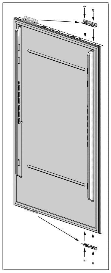
67 Install 1 cradle using the chipboard screws (28). You can also use the template (31) provided with the product to align these parts. It is recommended to keep this template for future reference. Attach 3 sheet metal brackets (25) using 2 screws (26) for each. 66
68 Attach the 3D adjusting mechanisms you have removed from the door to the door cradles. Attach the FRZ door handle. Screws holding the door handle must not protrude. 67
69 Use 4 screws to group the freezer inner door on the furniture door as shown in the figure below. 68
70 Attach the brackets to the freezer inner door, using 1 bolt (27) for each bracket and the Crescent Washers (12) specified below. A total of 3 mm washers must be placed on the FRZ Door (2+1) on the condition that all furniture dimensions are suitable. Washers to be used are determined based on the kitchen design. WARNING: You will find more Crescent Washers than you need in the mounting box. You can use them if your kitchen design requires so. 69
71 Kick Plate Position Adjustment: Nominal distance of the cabin's lower door from the ground is 4" (102 mm). It can be changed to a value between 2" (51 mm) and 6" (152 mm) by changing the freezer furniture door. The Lower Vent Hole can move 23 mm forward to be aligned with the Upper Vent Hole. 70
72 INSTALLING FURNITURE DOORS Installing the Fridge Furniture Door Hang the freezer furniture door assembly to the refrigerator using the hanger sheet. WARNING: Make sure that the positions of the 3D Adjusting mechanisms are correct. 71


73 Remove the Upper FF Door fixing bracket screw. Attach the FF Hanger Bracket (13) part in the mounting box to its place with the help of 2 screws (16). 72
74 73


75 Group the FF Upper Mechanism with 4 screws. Group the Lower Mechanism with 4 screws. 74


76 Remove 2 screws of the hanger part. Take out the hanger part. 75


77 Remove 2 screws of the Hanger Carrier. Take out the Hanger Carrier. WARNING: You must keep these parts for future use. You will need them if you want to change the door directions. Installing the Freezer Furniture Door Install the Freezer Furniture door assembly onto the rails. 76

78 Fix the Freezer Furniture door assembly onto the rails with 2 screws. 77
79 Adjusting the Furniture Door WARNING: The product may come with an Inox Door or as Furniture-mountable from the factory. If the product has an Inox Door, remove the brackets on the product before performing the adjustments below. Before starting to adjust the door, set the hardness level of the Fridge Door hinges to "0". 78
80 Remove 4 Fixing Brackets on the fridge door. 79

81 Loosen 3 bracket screws at the upper section of the freezer door. WARNING: These screws should never be removed. Number and dimensions of the Crescent Washers in-between will be changed based on the adjustment. 80

82 Remove 3 Fixing Brackets at the lower section of the freezer door. Position of the Furniture Doors to the kitchen furniture must be flush. To achieve this, You can use the 3D Adjusting system to perform fine adjustments: First of all, review the position of the grouped Furniture Doors against the kitchen furniture. Distances between furnitures must be 1/8" (3 mm), assuming that the furniture dimensions are correct. You can make door adjustments based on this distance. 81
83 82
84 Adjust the Furniture Doors with the 3D adjusting mechanism. You can adjust furniture doors with the 3-axis screw mechanism. Operating principle of the mechanisms are shown below. 83
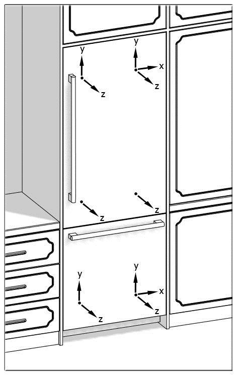
85 84

86 After completing door adjustments, attach the brackets to the middle section of the Fridge door. 85

87 Attach additional brackets to the upper and lower sections of the Fridge Furniture Door's handle part. 86

88 Tighten the screws together with enough Crescent Washers to cover the clearance under the upper brackets of the Freezer Door. 87


89 Attach the lower-middle bracket of the Freezer Door. Attach the lower side brackets of the Freezer Door. 88


90 Attaching the covers Attach and screw the Upper Cover of the Fridge Door. Attach and screw the Lower Door of the Fridge Door. 89
 (3).")
91 Attach the FRZ Cover (6) using the tabs. Attach the side closing seals (2) (3). 90

92 HINGE ADJUSTMENT Adjusting the hardness of the hinges Use a drill to adjust the hardness of the upper and lower hinges of the FF Door. Set the hinge adjustment screw to position "1" from position "0". WARNING: The door must be fully open during this adjustment. 91

93 WARNING: This adjustment must definitely be performed after the door has been adjusted. 92

94 CHANGING THE DIRECTION OF THE FF DOOR Removing the FF clad door Set the hardness level of the hinge to "0". ATTENTION: Failure to set the hinge to "0" and continuing the installation like that may cause injury. Remove the side closing seals. 93


95 Loosen one screw of the Upper Cover of the Fridge Door and remove it. Loosen one screw of the Lower Cover of the Fridge Door and remove it. 94

96 Remove FF Lower and Upper Bracket screws. Remove the screw of FF Upper and Lower mechanisms. WARNING: The clad door will be released when these screws are removed. You must take measures to prevent the door from falling. You can tape the Furniture Door to the Inner Door or ask for help from another person. 95

97 Take the Fridge Furniture Door and lay it down on a table upside down. You must attach the Furniture Door by rotating it 180 based on its current position. Fix the hanger sheet to its place with 2 screws. Remove the mechanism assemblies and attach them to the other side. Make sure that the "FF TOP" mechanism assembly is attached to the upper section of the door. 96
98 Removing and preparing the Fridge Inner Door Remove the hinge connection screws of the Hinge Brackets. ATTENTION: The clad door will be released when these screws are removed. You must take measures to prevent the door from falling. You can tape the Furniture Door to the Inner Door or ask for help from another person. 97

99 Take out the FF Door and lay it down on a table. Remove the Upper Hinge brackets on the FF Door and screw them to the other side of the door. 98
100 99
.")

101 Attach the Hanger Sheet (13) using 2 screws (16). Replacing the hinges Remove the Hinge Caps located at the other side where you will fix the hinges. 100

102 Remove the Screw caps of the hinges. 101

103 Remove the lower right hinge by loosening its 2 screws and fix it to its slot at the upper Left side. 102

104 Remove the upper right hinge by loosening its 2 screws and fix it to its slot at the lower Left side. 103

105 Fix the screw caps of the hinges to their places. 104

106 Attach the Hinge Slot Caps removed from the left side to the Hinge Caps at the right side. 105

107 Installing the FF PU Door Place the Fridge Inner Door to the refrigerator and fix it with 4 screws. 106

108 Installing the Fridge Furniture Door and adjusting the door Please see relevant chapters. INSTALLING THE DUAL CABIN If you are going to make a dual cabin installation, you must definitely demand "Dual Cabin Installation Kit" from the authorised service. The instructions below have been prepared according to Built-in type. Built-in: The Appliance and Panels fully seat into the gap, and a material that can be their own box is jammed between the two kitchen cabinets or decorative columns. This is the most common installation scenario. Cabin Dimensions Cabin dimensions below must be checked before starting the installation. 107

109 Location of the Electrical Wiring Location of the electrical wiring must be within the range given below. ATTENTION: Do not use extension cables or two-pin adaptors and do not remove the ground terminal of the grounding cable. ATTENTION: A qualified electrician must ensure that the poles of the socket are connected correctly. Verify that the grounding of the socket is correct. 108
110 Location of the Water System The water connected to the water mains must be potable. Location of the water system must be within the range given below. Water system of the refrigerator must be connected to the water mains system in the house. The user must be able to switch it on/off with the valve when necessary. Objects that might pierce the water hoses or cause them to twist must not be present where the water line is installed. Pressure of the water system must be between psi ( Bar). If the water pressure exceeds 80 psi, install a pressure limiting device or water impact protector to the inlet valve. Never install the product or operate the appliance if it is possible for the water pressure to exceed 120 psi. WARNING: Make sure that there is no water leakage when making the water connections. Otherwise, there will be water on the floor and the furniture will get damaged. You will need a hose with a minimum length of 60" (1.5 meters) and a diameter of ¼" for water connections of the product during installation. A connector that has a thread with an external diameter of ¼ must be used to connect the hose end to the product. Before completing the installation, make sure that water flows and there is no water leakage. 109
111 32 - Insulation Sponge 33 - Fastener 34 - Screw 110

112 Removing the Side Brackets Remove the side brackets that are located in the middle of two cabinets. 111

113 Attaching the Fasteners Screw (34) the Fasteners (33) that are going to be used to connect two refrigerators together to the locations shown in the figure. 112

114 Stick the Insulation Sponge (32) to the side panel so that the sponge remains in between two cabins. 113
")
115 Bring the two refrigerators side by side. After making sure that they are in alignment, screw the fasteners (33) to the other refrigerator. 114

116 Make power and water connections of the refrigerator as explained before. Push the refrigerators into the cabin. 115
117 Adjust the heights of the refrigerators. WARNING: First of all, raise the front feet to reduce the risk of the cabin falling frontward. A+B The Front Left section will rise if you push the left adjustment rod forward by 1" and rotate it clockwise C+D The Right Left section will rise if you push the right adjustment rod forward by 1" and rotate it clockwise A The Rear Left section will rise if you rotate the left adjustment rod clockwise C The Rear Right section will rise if you rotate the right adjustment rod clockwise 116
118 You can see previous pages for other installation procedures / AD 117
Installation Instructions
 Installation Instructions KFN 9855 ide en - CA Installation, repair and maintenance work should be performed by a Miele authorized service technician in accordance with national and local safety regulations
Installation Instructions
 Installation Instructions For Fully Integrated NoFrost Combined Refrigerator-Freezers HC 2060/2061 7082 485-00 Important PLEASE READ AND FOLLOW THESE INSTRUCTIONS These instructions contain Warning and
Installation Instructions
 Installation Instructions For Fully Integrated NoFrost Combined Refrigerator-Freezers HC 2062 HCB 2062 HC/HCB 20 7082 373-00 Important PLEASE READ AND FOLLOW THESE INSTRUCTIONS These instructions contain
Installation Instructions
 Installation Instructions For Fully Integrated NoFrost Combined Refrigerator-Freezers HCB 1560/1561 7084 429-00 Important Please read and follow these instructions These instructions contain Danger, Warning
Installation Instructions
 Installation Instructions For Fully Integrated NoFrost Combined Refrigerator-Freezers HCB 1560/1561 HC 1550 7084 327-00 Important Please Read and Follow these Instructions These instructions contain Danger,
Installation Instructions
 Installation Instructions For Fully Integrated NoFrost Combined Refrigerator-Freezers HC 2062 HCB 2062 HC/HCB 2062 7084 445-00 Important Please read and follow these instructions These instructions contain
Installation Instructions
 Instructions For Fully Integrated NoFrost Combined Refrigerator-Freezers HC 1540/1541 7084 433-00 Important Please read and follow these instructions These instructions contain Danger, Warning and Caution
Installation Instructions
 Installation Instructions For Fully Integrated NoFrost Combined Refrigerator-Freezers HC 2060/2061 HCB 2060/2061 7084 349-00 Important Please Read and Follow these Instructions These instructions contain
Installation Instructions
 Installation Instructions For Fully Integrated NoFrost Combined Refrigerator-Freezers HC 2062 HCB 2062 HC/HCB 2062 7084 341-00 Important Please Read and Follow these Instructions These instructions contain
INSTALLATION INSTRUCTIONS
 INSTALLATION INSTRUCTIONS BUILT-IN BOTTOM MOUNT REFRIGERATOR/FREEZER DBRTGK72SS-GRILLE KIT (FOR designer SERIES ONLY) VIKING RANGE CORPORATION 111 Front Street Greenwood, Mississippi (MS) 38930 USA (662)
Installation Instructions. Instructions de montage. Instrucciones de instalación HC
 Installation Instructions For Fully Integrated NoFrost Combined Refrigerator-Freezers Instructions de montage Pour le réfrigérateurs-congélateurs combinés NoFrost encastrés, pour une utilisation intégrée
INSTALLATION INSTRUCTIONS
 INSTALLATION INSTRUCTIONS BUILT-IN BOTTOM MOUNT REFRIGERATOR/FREEZER BRTGK72SS-GRILLE KIT (FOR PROFESSIONAL SERIES ONLY) VIKING RANGE CORPORATION 111 Front Street Greenwood, Mississippi (MS) 38930 USA
52 CEILING FAN READ AND SAVE THESE INSTRUCTIONS FAN RATING AC 120V.
 Irene 52 CEILING FAN READ AND SAVE THESE INSTRUCTIONS FAN RATING AC 120V. 60Hz TABLE OF CONTENTS Tools and Materials Required... 1 Package Contents... 1 Safety Rules... 2 Mounting Options... 3 Hanging
Installation Instructions. For the 18 Built-In Dishwasher and Front Color Panels
 Installation Instructions For the 18 Built-In Dishwasher and Front Color Panels Printed in USA 154232102 Before You Begin DO NOT INSTALL DISHWASHER UNTIL YOU HAVE READ ALL INSTRUCTIONS. FOR YOUR SAFETY,
Installation Instructions
 Installation Instructions For NoFrost Combined Refrigerator-Freezers with IceMaker CS/CBS 20 7084 337-00 Important Please Read and Follow these Instructions These instructions contain Danger, Warning and
Installation Instructions
 Installation Instructions For Free Standing NoFrost Combined Refrigerator-Freezers CS 1660 7082 653-00 PLEASE READ AND FOLLOW THESE INSTRUCTIONS These instructions contain Warning and Caution statements.
Owner s Guide and Installation Manual
 For Your Records and Warranty Assistance For reference, also attach your receipt or a copy of your receipt to the manual. Model Name Type 2A Models Owner s Guide and Installation Manual Model No. Date
INSTALLATION INSTRUCTIONS
 INSTALLATION INSTRUCTIONS BUILT-IN FULL HEIGHT WINE CELLAR (VCWB300 PROFESSIONAL MODEL) Retain for Future Reference VIKING RANGE CORPORATION 111 Front Street Greenwood, Mississippi 38930 USA (662) 455-1200
DAGNY LK. Ceiling Mounted Rotational Fan READ AND SAVE THESE INSTRUCTIONS. FAN RATING AC 110V~60Hz
 DAGNY LK Ceiling Mounted Rotational Fan READ AND SAVE THESE INSTRUCTIONS FAN RATING AC 110V~60Hz Please do not use any electric or battery powered tools in the assembly and installation of this or any
Owner s Guide and Installation Manual
 Tribeca Owner s Guide and Installation Manual English Form# M6001-01 20120416 2012 Casablanca Fan Co. Welcome Your new Casablanca ceiling fan is an addition to your home or office that will provide comfort
READ AND SAVE THESE INSTRUCTIONS
 READ AND SAVE THESE INSTRUCTIONS CEILING FAN INSTALLATION AND OPERATION INSTRUCTION FAN RATING AC 120V. 60Hz UL LISTED MODEL: AC-552OD WEIGHT OF FAN: 6.82 KGS 1. TOOLS AND MATERIALS REQUIRED Philips screw
INSTALLATION INSTRUCTIONS
 INSTALLATION INSTRUCTIONS BUILT-IN FULL HEIGHT WINE CELLAR Retain for Future Reference VIKING RANGE CORPORATION 111 Front Street Greenwood, Mississippi 38930 USA (662) 455-1200 IMPORTANT - PLEASE READ
Installation Instructions
 Installation Instructions For NoFrost Combined Refrigerator-Freezers with IceMaker CS 2060, CS 2061 7084 339-00 Important Please Read and Follow these Instructions These instructions contain Danger, Warning
Please read the following installation instructions first after purchasing this product or transporting it to another location.
 9 Installation Overview Please read the following installation instructions first after purchasing this product or transporting it to another location. 1 Unpacking your refrigerator 2 Choosing the proper
Owner s Guide and Installation Manual
 For Your Records and Warranty Assistance For reference, also attach your receipt or a copy of your receipt to the manual. Model Name Type 2A Models Owner s Guide and Installation Manual Model No. Date
1. SAFETY RULES. 8. Avoid placing objects in the path of the blades.
 1 1. SAFETY RULES 1. To reduce the risk of electric shock, insure electricity has been turned off at the circuit breaker or fuse box before beginning. 2. All wiring must be in accordance with the National
INSTALLATION INSTRUCTIONS
 INSTALLATION INSTRUCTIONS BUILT-IN BOTTOM MOUNT REFRIGERATOR/FREEZER Retain for Future Reference VIKING RANGE CORPORATION 111 Front Street Greenwood, Mississippi 38930 USA (662) 455-1200 IMPORTANT - PLEASE
Ceiling Fan Installation Instructions
 OWNER S MANUAL Ceiling Fan Installation Instructions Total fan weight For 3TF24XX Series Fans READ AND SAVE THESE INSTRUCTIONS QUALITY CEILING FANS Installation 1. 2. 3. 4. 5. 6. 7. 8. 9. 10. 11. 12. 13.
Installation Instructions
 Installation Instructions For Free Standing NoFrost Combined Refrigerator-Freezers CS 1660 7084 203-00 Important Please Read and Follow these Instructions These instructions contain Danger, Warning and
1. SAFETY RULES WARNING WARNING. 8. Avoid placing objects in the path of the blades.
 1 1. SAFETY RULES 1. To reduce the risk of electric shock, insure electricity has been turned off at the circuit breaker or fuse box before beginning. 2. All wiring must be in accordance with the National
Hanson LED C e i l i n g F a n
 Hanson LED C e i l i n g F a n model no. 052-8398-2 Toll-free 1-866-827-4985 IMPORTANT: For your safety please read and understand this manual before installing or operating this product. OWNER S MANUAL
Viking Installation Guide
 Viking Installation Guide Viking Range Corporation 111 Front Street Greenwood, Mississippi 38930 USA (662) 455-1200 For product information, call 1-888-VIKING1 (845-4641) or visit the Viking Web site at
Installation Instructions
 Installation Instructions For the 18" Built-In Dishwasher Sears, Roebuck and Co. Sears Canada, Inc. Hoffman Estates, IL 60179 U.S.A. Toronto, Ontario, Canada M5B 2B8 154435201 Before You Begin DO NOT INSTALL
Installation Instructions
 Installation Instructions Built-In Dishwasher If you have questions, call 800-GECARES or visit our website at: www.geappliances.com BEFORE YOU BEGIN Read these instructions completely and carefully. IMPORTANT
Owner s Guide and Installation Manual
 Tribeca Owner s Guide and Installation Manual English Form# M6000-01 20120416 2012 Casablanca Fan Co. Welcome Your new Casablanca ceiling fan is an addition to your home or office that will provide comfort
Installation Instructions
 Dear customer! Thank you for choosing this quality product from ASKO. We hope it will meet your expectations and fulfil your needs for many years to come. Scandinavian design combines clean lines, everyday
Installation GUIDE VDWU524SS VDWU524WSSS FDWU524WS FDWU524 VDWU324SS FDWU324
 Installation GUIDE VDWU524SS VDWU524WSSS FDWU524WS FDWU524 VDWU324SS FDWU324 To prevent accidents, which could cause serious injury or death, as well as machine damage read these instructions before installation
Viking Installation Guide
 Viking Installation Guide Viking Range, LLC 111 Front Street Greenwood, Mississippi 38930 USA (662) 455-1200 For product information, call 1-888-(845-4641) or visit the Viking Web site at vikingrange.com
C-IV 60 CEILING FAN READ AND SAVE THESE INSTRUCTIONS. FAN RATING AC 120V. 60Hz
 C-IV 60 CEILING FAN READ AND SAVE THESE INSTRUCTIONS FAN RATING AC 120V. 60Hz Please do not use any electric or battery powered tools in the assembly and installation of this or any Matthews Fan Company
DISHWASHER. Models DW2432 and DW2432SS. Installation Manual. Write Serial Number (on inner door of unit) here:
 here:") DISHWASHER Models DW2432 and DW2432SS Installation Manual Write Serial Number (on inner door of unit) here: Felix Storch, Inc. Summit Appliance Division 770 Garrison Avenue Bronx, New York 10474 www.summitappliance.com
DISHWASHER Models DW2432 and DW2432SS Installation Manual Write Serial Number (on inner door of unit) here: Felix Storch, Inc. Summit Appliance Division 770 Garrison Avenue Bronx, New York 10474 www.summitappliance.com
Table of contents. Planning guide for modular refrigerator, freezer and wine columns. Refrigeration 187. Installation options...
 Planning guide for modular refrigerator, freezer and wine columns. Table of contents Installation options............................. 188 Kitchen Design basic terms.................... 189 Cabinetry style
INSTALLATION MANUAL. Split-type Air Conditioner (Cooling and Heating) Outdoor Unit UQB09JJWC UQB12JJWC. Indoor Unit AQB09JJWC AQB12JJWC
 Outdoor Unit UQB09JJWC UQB12JJWC. Indoor Unit AQB09JJWC AQB12JJWC") AQB09JJ6WC_IM_E_2585 2006.4.17 4:26 PM Page 17 INSTALLATION MANUAL Indoor Unit AQB09JJWC AQB12JJWC Outdoor Unit UQB09JJWC UQB12JJWC ENGLISH FRANÇAIS ESPAÑOL Split-type Air Conditioner (Cooling and Heating)
AQB09JJ6WC_IM_E_2585 2006.4.17 4:26 PM Page 17 INSTALLATION MANUAL Indoor Unit AQB09JJWC AQB12JJWC Outdoor Unit UQB09JJWC UQB12JJWC ENGLISH FRANÇAIS ESPAÑOL Split-type Air Conditioner (Cooling and Heating)
Oscillating Ceiling Fan
 Oscillating Ceiling Fan model no. 052-8399-0 Toll-free 1-866-827-4985 IMPORTANT: For your safety please read and understand this manual before installing or operating this product. OWNER S MANUAL Toll
Built-In Dishwasher. Installation Instructions. BEFORE YOU BEGIN Read these instructions completely and carefully. IMPORTANT The dishwasher MUST be
 Installation Instructions Built-In Dishwasher If you have questions, call 800.GE.CARES (800.432.2737) or visit our website at: www.ge.com BEFORE YOU BEGIN Read these instructions completely and carefully.
Installation. Leveling
 Your refrigerator was packed carefully for shipment. Remove and discard shelf packaging and tape. Do not remove the serial plate. Location Do not install refrigerator near oven, radiator or other heat
Installation Instructions Built-In Dishwasher
 RINSE CHINA CRYSTAL SPEED CYCLE NORMAL WASH COOK WARE SELECTIONS ANTI BACTERIA START RESET ENHANCEMENTS DELAY HOURS ADDED HEAT PRE WASH HEATED DRY TO LOCK CONTROLS PRESS HEATED DRY FOR 3 SECONDS GE Consumer
CEILING FAN OWNER'S MANUAL
 CEILING FAN OWNER'S MANUAL READ AND SAVE THESE INSTRUCTIONS MODELS: 52-ECM-5RV-13 52-ECM-5RV- 52-ECM-5RV-SN FAN RATING AC 120V. 60Hz CUL LISTED MODEL : AC-552 1. TOOLS AND MATERIALS REQUIRED Philips screwdriver
Installation and Operation Manual For Hunter Ceiling Fans
 Installation and Operation Manual For Hunter Ceiling Fans 1 2 CONGRATULATIONS! Your new Hunter ceiling fan is an addition to your home or office that will provide comfort and performance for many years.
Installation Instructions
 GE Consumer & Industrial Appliances Installation Instructions Junction Box Cover Within this user bag, you will find a junction box cover and a #10 hex head screw used to attach the junction box cover
Ceiling Fan Installation Instructions
 OWNER S MANUAL Ceiling Fan Installation Instructions For 5SH54XXD-L Series Fans READ AND SAVE THESE INSTRUCTIONS Total fan weight with light kit 1. 2. 3. 4. 5. 6. 7. 8. 9. 10. 11. 12. 13. 14. 15. 16. 17.
60" Lyndon Patio. Instruction Manual Customer Service :30 AM to 5:00 PM EST, Monday - Friday A Kichler Decor ceiling fan
 60" Lyndon Patio TM 310140 A Kichler Decor ceiling fan Includes wall mount control system Kichler Lighting 7711 East Pleasant Valley Road P.O. Box 318010 Cleveland, Ohio 44131-8010 Instruction Manual Customer
Electrical cable Water supply tube Fittings for tube Coupler Teflon tape. Hole saw min. 2½" bit
 Installation Parts and Tools Parts not Provided Electrical cable Water supply tube Fittings for tube Coupler Teflon tape Air gap Wire nuts for 6-gauge wiring Hose clamp ⅞" UL approved strain relief Electrical
1. SAFETY RULES. 1. To reduce the risk of electric shock, insure electricity has been turned off at the circuit breaker or fuse box before beginning.
 Kichler Basics 403 1 1. SAFETY RULES 1. To reduce the risk of electric shock, insure electricity has been turned off at the circuit breaker or fuse box before beginning. 2. All wiring must be in accordance
60" Tulle PatioTM. Instruction Manual. A Kichler Select ceiling fan
 60" Tulle PatioTM A Kichler Select ceiling fan cul Certified for Wet Location Kichler Lighting 7711 East Pleasant Valley Road P.O. Box 318010 Cleveland, Ohio 44131-8010 Customer Service 866.558.5706 8:30
Dishwasher Installation Manual
 Dishwasher Installation Manual DW 51600 SS DW 51600 FBI DWT 51600 SS DWT 51600 FBI DWT 81800 FBI DWT 81800 SS DWT 81800 SSIH DWT 81800 SSWS DWT 52600 WIH DWT 52600 SSIH DWT 52600 BIH DWT 52800 WIH DWT
Liebherr's engineering excellence in Germany provides the largest selection of freezers, refrigerators and wine refrigerators worldwide.
 Design Guide Fully Integrated 30" and 36" Release 08 2015 2 Welcome Liebherr's engineering excellence in Germany provides the largest selection of freezers, refrigerators and wine refrigerators worldwide.
Installation Instructions
 Installation Instructions Above the Cooktop Microwave Oven PVM1899 & PVM2155 Questions? Call 1-800-561-3344 or Visit our Website at: GEAppliances.ca BEFORE YOU BEGIN Read these instructions completely
Installation. Built-in Full Height Wine Cellar VCWB301
 Installation Built-in Full Height Wine Cellar VCWB301 Table of Contents Warnings & Important Information _ 3 Dimensions _ 5 Specifications _ 6 Cutout Dimensions 7 Cabinet Information _ 8 Cabinet Information
INSTALLATION MANUAL. Split-type Air Conditioner (Cooling and Heating) Indoor Unit AQB18J6WC AQB24J2WC. Outdoor Unit UQB18J6WC UQB24J2WC
 Indoor Unit AQB18J6WC AQB24J2WC. Outdoor Unit UQB18J6WC UQB24J2WC") AQB8J6WC_IM_E_25864 2006.4.4 3:29 PM Page 7 INSTALLATION MANUAL Indoor Unit AQB8J6WC AQB24J2WC Outdoor Unit UQB8J6WC UQB24J2WC ENGLISH FRANÇAIS ESPAÑOL Split-type Air Conditioner (Cooling and Heating)
AQB8J6WC_IM_E_25864 2006.4.4 3:29 PM Page 7 INSTALLATION MANUAL Indoor Unit AQB8J6WC AQB24J2WC Outdoor Unit UQB8J6WC UQB24J2WC ENGLISH FRANÇAIS ESPAÑOL Split-type Air Conditioner (Cooling and Heating)
en-us Use and Care Manual, Installation Instructions Washer WAT28400UC
 en-us Use and Care Manual, Installation Instructions Washer WAT28400UC Under counter (Less Desirable) If front of the appliance is covered ventilation openings must be installed. E & F are minimum area
CEILING FAN OWNER'S MANUAL
 CEILING FAN OWNER'S MANUAL READ AND SAVE THESE INSTRUCTIONS MODEL: 52-771-5TK-13 52-771-5BW-SN 52-771-5WH-WH FAN RATING AC 120V. 60Hz CUL LISTED MODEL : AC-552A 1. TOOLS AND MATERIALS REQUIRED Philips
CEILING FAN OWNER'S MANUAL
 Style that revolves around you. CEILING FAN OWNER'S MANUAL VANTAGE with DC motor 12/14 WARNING: Read and follow these instructions carefully and be mindful of all warnings shown throughout. GENERAL INSTALLATION
ChicagoTM. Instruction Manual. Includes our new CoolTouch TM Control System Looks permanent, but goes wherever you go! U.S.
 Includes our new CoolTouch TM Control System Looks permanent, but goes wherever you go! U.S. Patent Pending ChicagoTM A Kichler Decor ceiling fan Kichler Lighting 7711 East Pleasant Valley Road P.O. Box
52 StarkkTM. Instruction Manual. A Kichler Select ceiling fan
 52 StarkkTM A Kichler Select ceiling fan Kichler Lighting 7711 East Pleasant Valley Road P.O. Box 318010 Cleveland, Ohio 44131-8010 Customer Service 866.558.5706 8:30 AM to 5:00 PM EST, Monday - Friday
Removing shipping locks
 y Safety instructions Scope of delivery Moisture in the drum is due to end inspection. Removing shipping locks Water connection l The washing machine is heavy - lift with caution. Frozen hoses can tear/burst.
Undercounter Refrigeration
 INSTALLATION GUIDE Undercounter Refrigeration Contents Undercounter Refrigeration..................... 3 Undercounter Specifications.................... 4 Site Preparation..............................
CEILING FAN OWNER'S MANUAL
 Style that revolves around you. CEILING FAN OWNER'S MANUAL Vail with DC motor 10/15 WARNING: Read and follow these instructions carefully and be mindful of all warnings shown throughout. GENERAL INSTALLATION
INSTALLATION GUIDE Dual Fuel Ranges
 INSTALLATION GUIDE Dual Fuel Ranges Contents Wolf Dual Fuel Ranges......................... 3 Safety Instructions............................ 4 Dual Fuel Range Specifications.................. 5 Dual Fuel
DISHWASHER INSTALLATION GUIDE SPECIFICATIONS, INSTALLATION, AND MORE
 DISHWASHER INSTALLATION GUIDE SPECIFICATIONS, INSTALLATION, AND MORE COVE DISHWASHER Contents 3 Cove Dishwasher 4 Specifications 7 Door Panel 9 Installation 15 Troubleshooting Features and specifications
42 Kevlar. Instruction Manual. Kichler Lighting 7711 East Pleasant Valley Road P.O. Box Cleveland, Ohio
 42 Kevlar Kichler Lighting 7711 East Pleasant Valley Road P.O. Box 318010 Cleveland, Ohio 44131-8010 Customer Service 866.558.5706 8:30 AM to 5:00 PM EST, Monday - Friday Instruction Manual 1 1. SAFETY
CEILING FAN OWNER S MANUAL
 CEILING FAN OWNER S MANUAL VERA CRUZ 5/04 GENERAL INSTALLATION & OPERATION INSTRUCTIONS IMPORTANT SAFEGUARDS: 1. To ensure the success of the installation, be sure to read the instructions and review the
Table of Contents. What to Expect with. Mounting Options. Tools Needed
 www.hunterfan.com Table of Contents What to Expect with Your Installation Congratulations on purchasing your new Hunter ceiling fan! It will provide comfort and performance in your home or office for many
LED. 60 StarkkTM. Instruction Manual. A Kichler Select ceiling fan
 60 StarkkTM LED A Kichler Select ceiling fan Kichler Lighting 7711 East Pleasant Valley Road P.O. Box 318010 Cleveland, Ohio 44131-8010 Customer Service 866.558.5706 8:30 AM to 5:00 PM EST, Monday - Friday
Bar Fridge USER MANUAL MB46W
 Bar Fridge USER MANUAL MB46W CONTENTS Safety information... 2-3 Identifying parts of the fridge... 4 Transporting... 5 Installation... 5 Reversing the door... 6 Operating instructions... 7 Cleaning &
Installation Instructions
 Installation Instructions Built-In Dishwasher If you have questions, call 800-944-9400(US),800-245-8352(Canada)or visit our website at: www.frigidaire.com BEFORE YOU BEGIN Read these instructions completely
Installation Instructions. K 1903 Vi, K 1913 Vi
 Installation Instructions K 1803 Vi, K 1813 Vi K 1903 Vi, K 1913 Vi en - CA Installation, repair and maintenance work should be performed by a Miele authorized service technician in accordance with national
CEILING FAN OWNER'S MANUAL
 CEILING FAN OWNER'S MANUAL READ AND SAVE THESE INSTRUCTIONS MODEL: 52-854-5RV-234 52-854-5RV-CH 52-854-5RV- FAN RATING AC 120V. 60Hz CUL LISTED MODEL : AG-962MC 1. TOOLS AND MATERIALS REQUIRED Philips
Liebherr's engineering excellence in Germany provides the largest selection of freezers, refrigerators and wine refrigerators worldwide.
 Design Guide Freestanding / Semi Built In 24", 30", 36", 48", 60", 72" Release 09 / 2018 Welcome Liebherr's engineering excellence in Germany provides the largest selection of freezers, refrigerators and
Installation Instructions 30 French Door Built-in Wall Ovens
 Installation Instructions 30 French Door Built-in Wall Ovens Questions? Call 1.800.GE.CARES (1.800.432.2737) or visit www.geappliances.com In Canada, call 1.800.561.3344 or visit www.geappliances.ca DESIGN
CEILING FAN OWNER S MANUAL
 Style that revolves around you. CEILING FAN OWNER S MANUAL Total fan weight *53 lbs. WEXFORD 11/05 WARNING: Read and follow these instructions carefully and be mindful of all warnings shown throughout.
Owner s Guide and Installation Manual
 For Your Records and Warranty Assistance For reference, also attach your receipt or a copy of your receipt to the manual. Model Name Type 8 Models Owner s Guide and Installation Manual Model No. Catalog
INSTALLATION INSTRUCTIONS
 INSTALLATION INSTRUCTIONS - Wall-mount indoor unit - OPERATING LIMITS Cooling Maximum conditions Heating Maximum conditions Outdoor temperature : 122 F (50 C) D.B. Outdoor temperature : 75 F (24 C) D.B.
Installation Instructions
 Instructions KWT 1603 SF en - CA Installation, repair and maintenance work should be performed by a Miele authorized service technician in accordance with national and local safety regulations and the
54" Skye. Instruction Manual Customer Service :30 AM to 5:00 PM EST, Monday - Friday A Kichler Decor ceiling fan
 54" Skye TM 300167 A Kichler Decor ceiling fan Includes wall mount control system Kichler Lighting 7711 East Pleasant Valley Road P.O. Box 318010 Cleveland, Ohio 44131-8010 Instruction Manual Customer
FitchTM. Instruction Manual. Includes our Basic Function CoolTouch TM Control System Looks permanent, but goes wherever you go!
 Includes our Basic Function CoolTouch TM Control System Looks permanent, but goes wherever you go! FitchTM A Kichler Décor ceiling fan U.S. Patent Pending Kichler Lighting 7711 East Pleasant Valley Road
CEILING FAN OWNER'S MANUAL
 CEILING FAN OWNER'S MANUAL READ AND SAVE THESE INSTRUCTIONS MODEL: 52-135-5WA-13 FAN RATING AC 120V. 60Hz CUL LISTED MODEL : AC-552OD 1. TOOLS AND MATERIALS REQUIRED Philips screw driver Blade screw driver
Installation. All Refrigerator / All Freezer VCRB5303 / VCRB5363 / CVCRB5303 / CVCRB5363 VCFB5303 / VCFB5363 /CVCFB5303 / CVCFB5363
 Installation All Refrigerator / All Freezer VCRB5303 / VCRB5363 / CVCRB5303 / CVCRB5363 VCFB5303 / VCFB5363 /CVCFB5303 / CVCFB5363 Table of Contents Warnings & Important Information _ 2 Professional Dimensions
Orrin. Instruction Manual. Includes our new CoolTouch TM Control System Looks permanent, but goes wherever you go! U.S.
 Includes our new CoolTouch TM Control System Looks permanent, but goes wherever you go! U.S. Patent Pending Orrin A Kichler Select ceiling fan Kichler Lighting 7711 East Pleasant Valley Road P.O. Box 318010
ValkyrieTM. Instruction Manual. Includes our new CoolTouch TM 6 Speed DC Control System Looks permanent, but goes wherever you go! U.S.
 ValkyrieTM A Kichler Décor ceiling fan Designed to coordinate with a popular Kichler Lighting collection. Includes our new CoolTouch TM 6 Speed DC Control System Looks permanent, but goes wherever you
Table of Contents What to Expect with Your Installation. Ceiling Plate. Tools Needed.
 Table of Contents Congratulations on purchasing your new Casablanca ceiling fan! It will provide comfort and performance in your home or office for many years. This installation and operation manual contains
CEILING FAN OWNER'S MANUAL
 Style that revolves around you. CEILING FAN OWNER'S MANUAL QUATRO 10/09 WARNING: Read and follow these instructions carefully and be mindful of all warnings shown throughout. GENERAL INSTALLATION & OPERATION
Dishwasher Installation Instructions DW 24XT/DW 24XV
 Dishwasher Installation Instructions DW 24XT/DW 24XV Installation Instructions Dishwasher BEFORE YOU BEGIN Read these instructions completely and carefully. IMPORTANT Observe all governing codes and ordinances.
Ceiling Fan Installation Instructions
 OWNER S MANUAL Ceiling Fan Installation Instructions Total fan weight For 5SKR52XXD Series Fans READ AND SAVE THESE INSTRUCTIONS QUALITY CEILING FANS Installation SAFETY TIPS WARNING: TO REDUCE THE RISK
Dishwasher. Installation manual DW60M9990AP
 Dishwasher manual DW60M9990AP DW9000M_DD68-00197B-00_EN.indd 1 6/1/2017 4:34:14 PM Contents Contents 3 What s included 3 requirements 7 Dimensions and specifications 9 Step-by-step installation 11 2 English
Hatteras BayTM. Patio. Instruction Manual. Includes our new CoolTouch TM Control System Looks permanent, but goes wherever you go! U.S.
 Hatteras BayTM Patio A Kichler Décor ceiling fan Designed to coordinate with a popular Kichler Lighting collection. Includes our new CoolTouch TM Control System Looks permanent, but goes wherever you go!
FerronTM. Instruction Manual A Kichler Decor ceiling fan
 Includes our new CoolTouch TM 6 Speed DC Control System Looks permanent, but goes wherever you go! U.S. Patent Pending 300160 A Kichler Decor ceiling fan HIGH EFFICIENCY DC MOTOR FerronTM Kichler Lighting
Model: AC-108. Instruction Manual
 Model: AC-108 Instruction Manual Attention: This appliance is not intended for use by persons (including Children) with reduced physical, sensory or mental capabilities or lack of experience and knowledge
CEILING FAN OWNER'S MANUAL
 Style that revolves around you. CEILING FAN OWNER'S MANUAL CIARA 12/14 WARNING: Read and follow these instructions carefully and be mindful of all warnings shown throughout. GENERAL INSTALLATION & OPERATION
CEILING FAN OWNER'S MANUAL
 Distinctive Lighting and Ceiling Fans CEILING FAN OWNER'S MANUAL MODEL: 52CW2L5-GM 52CW2L5-OBB READ AND SAVE THESE INSTRUCTIONS FOR CEILING FAN PARTS AND SERVICE, CALL 1-877-902-5588 FAN RATING AC 120V.
Select. Sutter PlaceTM. Instruction Manual. A Kichler Select ceiling fan
 Sutter PlaceTM A Kichler ceiling fan Kichler Lighting 7711 East Pleasant Valley Road P.O. Box 318010 Cleveland, Ohio 44131-8010 Customer Service 866.558.5706 8:30 AM to 5:00 PM EST, Monday - Friday Instruction