CERALIS GAS FIRE CERALIS XE GAS FIRE
|
|
|
- Kelly West
- 6 years ago
- Views:
Transcription
1 CERALIS GAS FIRE CERALIS XE GAS FIRE USER INSTRUCTIONS INSTALLATION INSTRUCTIONS SERVICE INSTRUCTIONS It is a regula on that these instruc ons be handed to the customer a er installa on is complete. It is also the responsibility of the installa on engineer to ensure that the customer is able to fully operate the appliance and is aware of any cleaning or maintenance requirements. This product is not suitable for primary hea ng purposes. Model numbers: F-011XX1 Manual Control for use on Natural Gas (G20) at a supply pressure of 20 mbar in GB / I.E. Model numbers: F-011XX2 Slide Control for use on Natural Gas (G20) at a supply pressure of 20 mbar in GB / I.E. (XX denotes Fuel Bed Type & Trim Type) P-XX1500 ISSUE7
2 CONTENTS Regulatory Informa on and Installa on Requirements... 3 Installa on Requirements (con nued).. 4 Si ng the Appliance 5 Fixing the Appliance Connec ng the Appliance to the Gas Supply.. 8 Checking Opera on of Appliance 8 Comple ng the Installa on 9 Appliance Technical Informa on 10 Cleaning Instruc ons.. 10 Service Instruc ons User Instruc ons.. 13 Coal Layout Instruc ons.. 14 Pebble Layout Instruc ons Product Fiche 20 Spare Parts List.. 21 Manufacturer s Contact Details 23 2
3 REGULATORY INFORMATION AND INSTALLATION REQUIREMENTS THE FOLLOWING MUST BE NOTED PRIOR TO THE INSTALLATION OF THIS APPLIANCE. This gas appliance MUST be installed by a GAS SAFE registered installer by law. It must be installed in accordance to these installa on instruc ons and the GAS SAFETY (Installa on & Use) REGULATIONS 1998 as amended. Non compliance of this law may lead to prosecu on and it is in the interest of you and your family that this condi on is observed. The installa on of this appliance must be in accordance with the relevant parts of the LOCAL AND NATIONAL BUILDING REGULATIONS as issued by the Department of the Environment or BUILDING STANDARD (Scotland Consolida on) REGULATIONS issued by the Sco sh Development Department and the following relevant Bri sh Standards: BS5871 Part 2 Installa on of Inset Live Fuel Effect Gas Fires BS5440 Parts 1 & 2 Installa on of Flues and Ven la on BS6891 Installa on of Gas Pipe-work BS6461 Part 1 Installa on of Chimneys and Flues BS1251 Open Fireplace Components BS715/BS EN Metal Flue Pipes for Gas Appliances BS EN 1858 / BS1289 Chimneys Components & Concrete Flue Blocks IS813:1996 Domes c Gas Installa on (Republic of Ireland) Prior to installa on ensure that the gas supply is compa ble with the appliance, this appliance must only be used on natural gas at a supply pressure of 20 mbar as marked on the data plate on the appliance and the carton. This appliance is only to be installed into a builder opening which must be constructed of non-combus ble materials confirming to BS1251 or a suitable flue-box complying with the requirements of BS715/BS EN If the product is being installed into a builders opening the chimney must be at least 3 metres in height and should be swept before installa on if it has been used for the burning of solid fuel (e.g. coal or wood). The chimney must only serve as a flue-way to this appliance and must have no openings to any other room. The opening should be inspected and any exposed brickwork should be repaired where necessary. The chairbrick (if applicable) should be removed unless the minimum depth of the fireplace exceeds 175mm. If the depth is less than 175mm then the chair brick MUST be removed. If the product is being installed into a fabricated Flue-box it must be installed onto a non-combus ble surface with a thickness of at least 12mm. This fireplace is also suitable for installa on into precast flue fireplaces which comply to the requirements of BS EN1858/ BS1289. If the appliance is being installed into a concrete precast flue manufactured in accordance with BS1289:1975 the flue duct area is less than 13,000mm 2 in accordance with BS5440 part 1. In this type of installa on no other flue restrictors (ie XE kit restrictors) can be used. It is important to note that pre-cast flue systems should be constructed with an air gap or some form of insula on material between the flue block and the plastered face; pre-cast flue systems with a plastered face directly in contact with the flue block are not correctly installed and installa on of this appliance into such a flue system may result in the plaster cracking above the appliance. Flue-way must be through a Class I (7 or 175mm diameter) or Class II (5 or 125mm diameter) flue of at least three meters in height. The flue should be checked for draw using a smoke bomb or similar, if there is a definite draw then the installa on of the appliance can proceed. 3
4 No purpose made ven la on is normally required for this appliance when installed in G.B. If the appliance is being installed in I.E then refer to I.S 813:1996 (Domes c Gas Installa on Na onal Standards Authority of Ireland). Ven la on areas (if applicable) should be checked periodically to ensure there is no obstruc on, even though none is normally required for this appliance. IMPORTANT NOTE: If the appliance being installed is an XE model then the XE restrictor supplied in the XE FITTING PACK should be fi ed (Ensure the restrictor being fi ed states the model number F-011XXX). It is mandatory that when fi ng the XE restrictor, that baffle fi ed during manufacture is first removed and the XE CANOPY also must be fi ed. When installing the XE restrictor onto an appliance where the flue is 7 (or 9 brick chimney) and of a minimum height of at least 5 metres, the addi onal restrictor (supplied in the XE pack also) can also be fi ed for addi onal efficiency. It is mandatory that the safe clearance of products be checked by performing a smoke match test as described on the product data label. SPILLAGE TEST: To check for sa sfactory clearance of products of combus on, close all doors and windows and leave the appliance burning on HIGH for five minutes. Insert a lit smoke match just into the top of the fire opening and move it le and right, all the smoke must be drawn into the flue. If spillage occurs allow a further 5 minutes and repeat the test. If spillage s ll occurs turn off the appliance and seek expert advise to expert advice. If an extractor fan is situated in the room the spillage test should be repeated with the fan running. If there is a connec ng room with an extractor fan the test should be repeated with all the doors to that room open and the extractor fan running. If the appliance spills with the restrictor fi ed then the restrictor should be removed and the spillage test repeated. If the spillage test con nues to fail expert advise should be sought and addi onal ven la on may have to be provided. This appliance must only be installed on to a suitable hearth with a minimum thickness of 12mm. The appliance must not be installed directly onto carpet of other combus ble floor materials. The fireplace surround (back-panel) must have a temperature ra ng of at least 150 o C. Do not place so wall coverings (i.e. embossed papers etc,) furniture or other combus ble items too close to the fires as they may discolour or scorch. Do not place or throw rubbish or otherwise on the fuel-bed. Do not place any combus ble materials or flooring (i.e. carpets etc,) on any part of the hearth. WARNING: This appliance has a naked flame and as with all hea ng appliances a fireguard should be used for the protec on of children, the elderly and infirm. The fireguard should conform to BS8423 : 2002 (Fireguards or use with Gas Hea ng Appliances). Important Note: It is quite normal for a flame effect gas appliance to experience a small amount of soot or staining to some parts of the fuel effect components. If this becomes excessive it may because the fuel bed is not fi ed correctly this should be checked according to these installa on instruc ons prior to contac ng a service engineer. It is very important that you arrange for a GAS SAFE registered engineer to service your appliance every year during this service the engineer will remove the appliance and check for debris, check the opera on of the flue and check the opera on of the appliance. This is important for you and your families safety. NEVER place any rubbish or otherwise onto the fire this will affect the way the product operates and may affect the warranty of the product. NEVER place more ceramic components onto the fuel bed than specified in the instruc ons. NEVER touch the ceramics when the appliance has recently been switched off these components retain heat and may cause burns. Leave the appliance to sufficiently cool prior to any contact of the ceramics. 4
5 SITING THE APPLIANCE Fireplace Opening The fireplace opening must be between 405mm and 450mm wide and between 555mm and 570mm high. If the opening intended for the appliance is in excess of these dimensions then a suitable surround must be constructed of non-combus ble material to produce an opening within this range of dimensions. A flat face of a minimum 470mm wide and 590mm high must be provided around the fireplace opening to ensure a good seal is formed. In addi on it is important to ensure that the base of the fireplace opening is flat and level with the hearth surface to ensure a secure and aligned installa on of the appliance. The minimum hearth dimensions are shown in the diagram above. The upper surface of the hearth must be a minimum of 50mm above the floor and must protrude a minimum distance of 300mm out from the fireplace opening. (It is important to note that should a spacer of any kind be used to bring the appliance out of the fireplace, then the 300mm dimension must be taken from the most forward surface of this spacer. Installa on into a Brick Chimney When the appliance is being installed into a brick chimney there must be sufficient depth behind the appliance to accommodate any falling debris. This debris collec on void should be capable of accommoda ng up to twelve (12) litres of volumetric space. Installa on into a Prefabricated Twin Wall Metal Flue Box This appliance can be installed into a prefabricated metal twin wall flue box providing it complies to the requirements of BS715 / BS EN The box must have an insulated flue with a minimum diameter of 125mm (5 ) diameter and a minimum effec ve overall height of 3 metres. The top outer face of the flue box should be insulated to prevent heat loss with a layer of mineral wool insula on or similar. The metal flue box must stand on a non-combus ble surface with a minimum thickness of 12mm. Installa on into a PRE-CAST FLUE Installa on If the XE product is being fi ed see IMPORTANT NOTE on page 4 of these instruc ons. Ensure that there is a minimum of 125mm from the front of the fireplace opening to the rear of the flue starter block this is to ensure that sufficient clearance is allowed for debris collec on. 5
6 Installa on into a PRE-CAST FLUE Installa on con nued If a dimension of 125mm cannot be achieved to provide such debris collec on then the fire surround can be packed away from the wall ensuring that that a suitable non combus ble material is used and the integrity of the fireplace opening is maintained. If this procedure is undertaken then it is important to ensure that the correct mantel rebate is selected to provide for this new fire surround posi on. Under no circumstances should the appliance be installed if the 125mm minimum dimension cannot be achieved. The installer should always inspect the flue way prior to installa on of the appliance and in the case of pre-cast flues it is important to check that the flue way is clear and free from mortar or other sealant which may have been extruded into the passage during its construc on. If this is the case then these should be removed by rodding the flue prior to installa on. See the other important notes regarding pre-cast flues on page 3. Fireplace Opening (Hole in the Wall Installa on) This appliance MUST be installed in accordance with all relevant sec ons of document J of the building regula ons. This appliance may be installed such that the base of the appliance sit on the surface of a fireplace opening at least 110mm up from the floor this dimension ensures that there is no incandescent material (flame or ceramic impinged by flame) is less than 225mm from the floor. This is a requirement of document J. Where a hole in the wall installa on is employed it is important that the fret to the appliance is either integral with the trim, is fixed to the appliance securely or a small hearth surface is constructed at the base of the opening for the fret to sit upon. If such a hearth is constructed it must be a minimum of 480mm in width and 100mm deep. It is always important to ensure that the appliance is fixed securely to the fireplace opening and that no movement of the ceramics takes place when the appliance is operated. It is addi onally important in a hole in the wall installa on to ensure loose ceramics cannot fall from the appliance. In addi on it is impera ve that ONLY fascia/trim arrangements supplied by Hearth Products deemed suitable to be used with Hearth Products appliances in a hole in the wall installa on shall be used. THE INSTALLER MUST INFORM THE USER OF THE FOLLOWING IMPORTANT NOTICES AFTER A HOLE IN THE WALL INSTALLATION HAS BEEN UNDERTAKEN. 1. The user must be made aware to fit a secure fireguard where the room is used by elderly, infirm, infants or young children. 2. The customer should be advised to fit a hearth panel or a physical barrier in accordance with BS Should this advice not be followed the customer should be advised to give due to considera on to the safety of the occupants in the room where the appliance is to be installed. 3. The user must be made aware to keep the area immediately in front of the appliance must always be kept clear of combus bles items. This does not include the floor covering however such covering should be fixed. 4. The user must ensure that the ceramic fuel bed is maintained in the correct condi on of installa on, especially a er cleaning. If the fuel bed is removed for cleaning or maintenance the ceramics should be checked for secure placing and tested for movement during appliance opera on. 5. The user must ensure that other occupants of the room where the appliance is installed are no fied to not get unnecessarily close to the appliance when in use or to posi on any furniture or appliances too close to the fire. Checking the Flue Use a smoke pellet prior to the appliance installa on to ensure the viability of the flue and check that the smoke can be seen being emi ed from the terminal / chimney pot outside. There must be no leakage of smoke through the structure of the chimney/flue during or a er the smoke pellet test and it is important to check inside upstairs rooms adjacent to the chimney/flue. If the installa on is into a pre-cast flue ensure check the lo space to ensure that the connec on between the pre-cast block and the fluepipe is sound. Check the chimney pot / terminal and general condi on of the brickwork or masonry. If the chimney or flue is in poor condi on or if there is no up-draught do not proceed with the installa on. If there is a history of down-draught condi ons with the chimney / flue, the installa on of a tested and cer ficated flue terminal or cowl suitable for the relevant flue type should be considered. A spillage test must be performed see page 4 of these instruc ons. 6
7 Fixing the Appliance. If the appliance is being installed with a spacer kit, this should be a ached to the appliance using the screws included and the second foam length which is supplied with the spacer kit should be affixed to the rear face of the spacer. Do not use any permanent sealing substance as this will invalidate warranty as the appliance cannot be removed for periodical inspec ons. Cable Fixing System (Supplied as standard) This appliance is best installed with the cable fi ng system which is supplied in the standard fi ng pack. The fi ng system comprises four (4) eyebolts,, two (2) fixing cables, two (2) screwed nipples and two (2) adjuster fi ngs. This installa on requires that the burner tray is removed from the firebox. Remove the screws securing the burner tray to the firebox and set the tray aside during the firebox installa on. Simply drill and fit the eyebolts in the posi ons shown in the next diagram. Then thread the fixing cables through the two small holes at the top/rear of the appliance, pass each cable through two of the eyelets then back through the one of the two holes at the rear of the appliance. Thread the cable through the adjuster fi ngs. When the appliance is in its installed posi on, pull the cables ght and slide the adjuster to the back of the fire ensuring the back-nut on the adjuster has been run as far up the thread as possible to the hexagon shoulder. Keeping the cable ght, fit the screwed nipple to the cable and secure. Turn the back-nut on the adjuster fixing and the cable will be tensioned un l the appliance is securely fixed. Spillage monitoring System This appliance is fi ed with an atmospheric sensing system in the form of an oxygen sensing pilot burner. This is designed to shut the fire off in the event of products being spilled into the room where the fire is being operated. It is important to note that this spillage monitoring device should not be disabled or be adjusted by the installer. If the spillage monitoring device (O.D.S pilot) is replaced it must only be exchanged with a suitable component which is supplied by Hearth Products Ltd. Combus ble Shelf This appliance may be fi ed below a surround with a combus ble shelf providing the following dimensional criteria is met: There must be a minimum distance of 250mm from the top of the appliance to the underside of the shelf. The shelf must not project more than 150mm from the moun ng surface of the appliance into the room. If the shelf projects more than 150mm then the distance between the top of the appliance and the underside of the shelf must be increased accordingly; for every 10mm of projec on above 150mm the distance between the fire and shelf must be increased by 20mm Shelf Protrusion 150mm 160mm 170mm 180mm 190mm 200mm Min. Distance Between Fire and Shelf 250mm 270mm 290mm 310mm 330mm 350mm 7
8 Connec ng the Appliance to the Gas Supply The gas supply can be connected to the appliance by a concealed fi ng from the rear. In all installa on condi ons the gas connec on should be provided using 8mm (O/D) copper tubing. If the concealed installa on method is chosen, there are three op onal entry points at the rear/side of the appliance. The relevant knock-out entry point should be removed to allow the gas supply to enter the appliance. No soldered joints should be used with the firebox of the appliance. The blind grommet which is supplied in the standard fi ng pack should be used to close up the knock out hole simply cut a small cross with a sharp knife in the centre of the grommet this will then seal around the gas pipe to provide a ght seal. Under no circumstances should this gas entry hole be le open and unsealed as this can result in flame reversal and can cause damage to the appliance. Should this occur the warranty to this appliance will be rendered void. Before connec ng the gas supply to the appliance a gas soundness test should be performed to ensure that the exis ng pipe work in the property is sound. The burner tray can now be reinstalled into the firebox. The gas connec on should be made to the appliance by the 8mm restrictor isola on valve supplied with the appliance. This restrictor elbow is supplied loose and should be fi ed as per the label on the instruc on packet. Install the ceramics on to the appliance according to these instruc ons see page 14. Test the opera ng pressure of the appliance by a aching a pressure gauge to the test point of the appliance. This connec on should take place when the appliance is OFF. Ensure that gas is turned on at the gas meter and purge the air from the appliance by: MANUAL CONTROL UNITS: Rotate the control to the (IGN) posi on and push in, now press the igniter bu on. Con nue to press the igniter bu on un l the pilot lights. Check that the spark is being generated correctly at the pilot assembly. Con nue with this procedure un l the air is purged from the appliance and the pilot is lit. Once lit hold the valve pushed in for up to 30 seconds. Once the pilot is established and secure, turn the control knob an -clockwise to the (HIGH) posi on. Allow the appliance to run for a minimum period of 5 minutes. Next check that the inlet pressure to the appliance is at 20 mbar ±1 mbar. SLIDE CONTROL UNITS: Push down the control lever fully to the (IGN) posi on and hold. The spark generator should spark con nuously, ensure the spark is being generated correctly at the pilot assembly. Con nue with this procedure un l the air is purged from the appliance and the pilot is lit. Once lit hold the lever pushed down for up to a further 30 seconds. Once the pilot is established and secure allow the lever to rise to the (LOW) posi on then li the lever to the (HIGH) posi on. Allow the appliance to run for a minimum period of 5 minutes. Next check that the inlet pressure to the appliance is 20 mbar ±1 mbar. Check the opera on of the appliance according to these instruc ons see page 13. Check the clearance of combus on products SPILLAGE TEST: To check for sa sfactory clearance of products of combus on, close all doors and windows and leave the appliance burning on HIGH for five minutes. Insert a lit smoke match just into the top of the fire opening and move it le and right, all the smoke must be drawn into the flue. If spillage occurs allow a further 5 minutes and repeat the test. If spillage s ll occurs turn off the appliance and seek expert advise to expert advice. If an extractor fan is situated in the room the spillage test should be repeated with the fan running. If there is a connec ng room with an extractor fan the test should be repeated with all the doors to that room open and the extractor fan running. 8


9 Comple ng the Installa on of the Appliance Remove the protec ve covering (if applicable) from the face of the decora ve trim. Fit the trim to the appliance with the magnets provided. One magnet should be placed in each corner of the trim at the top of the appliance and on each side about 120mm from the base of the appliance. In the case of slide control appliances care should be taken that the magnet does not come into contact with any moving parts of the lever mechanism. This advice should also be passed onto the consumer to ensure that they are aware of magnet posi oning. A service call due to incorrect placement of magnets which cause difficulty in ligh ng the appliance will result in a callout charge being made. Posi on the fret in front of the appliance ensuring that it meets the following requirements. THE INSTALLER MUST INFORM THE CUSTOMER OF THE FOLLOWING TO COMPLETE THE INSTALLATION Demonstrate the ligh ng of the appliance and the controls to control the heat se ngs. Demonstrate how to ex nguish the fire. Demonstrate the removal of the trim and fret and how to reinstall correctly. Discuss the removal and reinstalla on of the ceramics. Explain how they should be cleaned and make the customer aware of the health and safety warning detailed later in these instruc ons. Explain to the customer that the ceramics are fragile and must be treated with great care, explain that the ceramics are not covered by the warranty because of their fragility. Also explain that small hairline cracks will appear in the surface of the ceramics due to heat expansion and contrac on this is perfectly normal. During the first several hours of use an odour will be experienced this is normal and is the starch used in the manufacturing of the ceramic fuel bed. This odour is non toxic and will eventually disappear with use. Advise that no rubbish should be thrown onto the appliance and that the appliance should be cleaned regularly. A vacuum cleaner can be used but it is important that the appliance is turned off and allowed to cool before undertaking this procedure. See the separate sec on regarding cleaning the ceramics. Advise the customer that the appliance should be serviced annually by a gas safe engineer to ensure the safety and integrity of the appliance. Advise the customer that the appliance has a naked flame and therefore it is essen al that a suitable fireguard be used for the protec on of the elderly, infirm and young children. This fireguard should conform to BS8423 : 2002 (Fireguards or use with Gas Hea ng Appliances). These instruc ons must be handed over to the customer once installa on is complete. 9
 20mbar Heat Input Gross : 6.")
10 Maintenance of the Appliance The following procedures can and should be performed by the customer at regular intervals depending upon use of the appliance. Appliance Technical Informa on Gas Type : Natural Gas Category : I2H Inlet Pressure: (Cold) 20mbar Heat Input Gross : 6.75kW Injector : 77 Des na on Countries : GB/ IE HEALTH AND SAFETY NOTICE This appliance uses fuel effect pieces manufactured from Refractory Ceramic Fibres (RCF). Care must be taken to avoid excessive exposure to these materials as they may cause irrita on to the eyes, skin, nose and throat. When Handling avoid inhaling and contact with skin and eyes. It is recommended that disposable gloves are worn in addi on to a facemask and eye protec on. A er handling wash hands thoroughly and any other exposed parts which may have come in to contact with the material. If a vacuum cleaner is used to clean the fuel bed or areas around the appliance there fragments of the material may have fallen it is recommended that it be of the type fi ed with a HEPA filter. Care should be taken when disposing of RCF materials. It is important to keep any dust to a minimum so it is recommended that the fuel effect components are placed into a heavy duty plas c bag. The bag should be clearly labelled RCF WASTE. These materials are not classified as hazardous waste and should be disposed of at a site approved for the disposal of industrial waste. Cleaning the Appliance Fuel Bed The fuel effect components supplied with this product are extremely fragile and must be handled with great care. The ceramics in this appliance are not covered by the warranty due to their fragility. This includes the RCF fibre boards in the fire box. These components will break or chip if not handled with the greatest of care. Cleaning of these components should only be undertaken once the appliance is switched off and has been allowed to cool for a minimum period of one hour. The components should be li ed carefully piece by piece from the appliance and placed onto a dust sheet or similar. They can be brushed gently with a so brush to remove any dust or deposits. If you intend to use a vacuum cleaner then this should only be done once the loose deposits of soot etc have been removed. Ensure that the moulded components are structurally sound and no significant part of the moulding has broken away. If any component has broken then it should be replaced before using the appliance. Only the correct replacement part as supplied by the manufacturer shall be used in this appliance. Do not add any addi onal components to the fuel bed layout. It is important to note that small hairline cracks will appear in the surface of the ceramics due to heat expansion and contrac on this is perfectly normal. Pilot The pilot to this appliance has a small aera on hole at its base. Using a thin nozzle on a vacuum cleaner this area can be cleaned to prevent a lint build up. This procedure should only be undertaken when the appliance is off and cold. If excessive lint is drawn in through this hole due to infrequent cleaning then it may result in the appliance not ligh ng or turning itself off automa cally due to a starva on of air at the pilot burner. This can o en be remedied by performing the cleaning opera on detailed here. If this procedure does not resolve such a problem then the pilot assembly will need to be replaced. This must involve the installa on of the same part as supplied by the manufacturer. Excessive lint build up which results in appliance opera onal problems is not covered by warranty. It is important to ensure this preventa ve maintenance is performed regularly (once a month during the winter period). 10


11 Cleaning the Appliance (con nued) Trim, Fret and Painted Metal Parts There are a variety of trim and fret op ons which may have been supplied with your appliance and these are normally a plated material on a steel substrate. It is important that no abrasive cleaners or chemical agents are used in the cleaning of these components. It is recommended that all these surfaces including the painted metal parts are cleaned with a clean damp (not wet) cloth. Cleaning should only take place when the appliance is switched off and has been switched off for a minimum period of one hour. The following procedures can and should only be performed by a Gas Safe registered installer. This appliance should be serviced annually by a Gas Safe registered installer. Removal / Replacement of Gas Carrying Components. The removal and replacement of all the gas carrying components will require the removal of the burner tray. The following informa on details the removal of this tray. Once removed, refer to the relevant sec on that follows detailing the removal of the specific component (s). Turn off the gas supply at the isola on valve on the appliance. Ensure the appliance is cold. Remove the fret and the trim put in a suitable loca on where they cannot be damaged or scratched in anyway. Remove the fuel effect components - put in a suitable loca on where they cannot be damaged. Disconnect the gas supply from the restrictor elbow. Slide Control models only: Disconnect the pushrod retaining screw from the base of the rod. Remove the screws securing the burner tray to the firebox as detailed in the diagram. Re-assemble the tray in the reverse order. Manual Control Models Slide Control Models Now carefully pull the burner tray from the fire box. The burner tray is can now be serivced or repaired accordingly see the following pages for informa on about removing and replacing serviceable components. 11


12 Removal / Replacement of Gas Carrying Components (con nued) Replacement of the Gas Control Valve Manual Control Valve 1. Remove the control knob from the valve. 2. Remove the locknut from the front of the valve. 3. Undo the three nuts around the periphery of the valve body Gas Inlet / Burner / Pilot 4. Remove the thermocouple nut from the back of the valve. 5. The valve can be removed and serviced / replaced as necessary. 6. Re-assemble in reverse order. 7. Re-assemble the burner tray in to the firebox (see previous page) Slide Control Valve 1. Remove the locknut from the front of the valve. 2. Undo the three nuts around the periphery of the valve body Gas Inlet / Burner / Pilot 3. Remove the thermocouple nut from the back of the valve. 4. The valve can be removed and serviced / replaced as necessary. 5. Re-assemble in reverse order. 6. Re-assemble the burner tray in to the firebox (see previous page) Replacement of the Pilot 1. Remove the four (4) screws to remove the cover panel. 2. Undo the pilot gas supply from the base of the pilot 3. Remove the thermocouple nut from the back of the valve. 4. Remove the two (2) screws securing the microswitch, see diagram 5. Remove the HT lead from the electronic igniter unit. 6. Remove the two (2) screws securing the pilot to the burner tray. 7. The pilot assembly can be removed and replaced. 8. Re-assemble in reverse order. 9. Re-assemble the burner tray into the firebox (see previous page) Replacement of the Burner Tray 1. Remove the screws securing the tray to the firebox. 2. Remove the burner tray from the appliance 3. Re-assemble in reverse order. 4. Re-assemble the burner tray into the firebox (see previous page) Replacement of the Injector 1. Remove the brass nut from the injector elbow. 2. Unscrew the injector elbow from the burner assembly. 3. The injector can be removed and replaced. 4. Re-assemble in reverse order. 5. Re-assemble the burner tray into the firebox (see previous page) Only replacement components supplied by the manufacturer should be used in the service of this appliance. Contact details for Hearth Products Ltd can be found on the back page of these instruc ons. 12
13 OPERATING INSTRUCTIONS This appliance is available with two opera ng methods, namely manual control and slide control. The following instruc ons detail both methods of opera on however the basic opera on of the appliance involves the igni on of a pilot burner (See page 7 for spillage monitoring details ODS), then the control of the main burner with LOW and HIGH se ngs. This appliance has a naked flame and as with all hea ng appliances a fireguard should be used for the protec on of children, the elderly and infirm. The fireguard should conform to BS8423 : 2002 (Fireguards or use with Gas Hea ng Appliances). MANUAL CONTROL OPERATION 1. Push the control knob in fully then rotate an -clockwise to the IGN symbol. Now press the spark generator which should cause a spark at the pilot and the pilot should ignite. If the pilot does not light rotate the control knob to the OFF posi on and retry. If the pilot does not light on the second a empt then return the control knob to the OFF posi on and wait for 3 minutes. 2. Once the pilot is lit keep the control knob pushed in fully for up to 30 seconds. 3. Now release the control knob, the pilot should remain lit. If it goes out, wait for 3 minutes and return to step To turn the appliance to the LOW se ng, turn the control knob an -clockwise to the flame symbol. 5. To turn the appliance to the HIGH se ng, turn the control knob an -clockwise to the flame symbol. 6. It is also possible to adjust the control knob between the and the flame symbols to achieve a mid se ng. 7. To turn the fire off, press the knob slightly and turn to the IGN symbol (for pilot only) or symbol to turn off. IMPORTANT NOTE: Should the spark generator fail to provide a spark at the electrode it may be that a small amount of soot has fallen from the fuel bed onto the pilot assembly, causing a short circuit. If this is the case, ensuring the appliance is off and cold, this area can be cleaned with the thin nozzle from a vacuum cleaner. It is also possible to light the pilot burner with a long taper whilst the control knob is being held in at the IGN symbol. SLIDE CONTROL OPERATION 1. Push the control lever down fully to the IGN symbol. The spark generator should cause a repe ve spark at the pilot and the pilot should ignite. If the pilot does not light a er 10 seconds then li the control lever upwards to the OFF symbol and wait for 3 minutes. 2. Once the pilot is lit keep the control lever pushed down fully for up to 30 seconds. 3. Now slowly li the control lever to the symbol, the pilot should remain lit and the burner will be in the LOW se ng. If it goes out, wait for 3 minutes and return to step To set the appliance to the HIGH se ng, li the control lever upwards to the flame symbol. 5 It is also possible to adjust the control knob between the and the flame symbols to achieve a mid se ng. 6 To turn the fire off, li the lever to the symbol. IMPORTANT NOTE: Should the spark generator fail to provide a spark at the electrode it may be that a small amount of soot has fallen from the fuel bed onto the pilot assembly, causing a short circuit. If this is the case, ensuring the appliance is off and cold, this area can be cleaned with the thin nozzle from a vacuum cleaner. Alterna vely check the ba ery is in good condi on the ba ery access cover is at the base of the appliance just le of centre. (Slide models only). It is also possible to light the pilot burner with a long taper whilst the control knob is being held in at the IGN symbol. 13


14 FUEL BED LAYOUT (COAL) The following instruc ons detail how the ceramic fuel bed and loose components are to be installed onto the appliance. Great care should be taken when handling these ceramic parts as they are fragile and can easily be broken. Do not force any component into posi on, if it does not fit easily then you are not fi ng the part correctly. These instruc ons can also be followed to remove or reinstall the fuel bed a er cleaning. This is a procedure that can be undertaken by the customer as required and the frequency will be depend upon use. Step 1 Fit the fuel bed into the appliance as shown in the picture below. Step 2 Fit the front ceramic rail in front of the burner as shown in the picture below. 14


15 Step 3 Fit the two side cheeks into posi on as shown in the picture below. These are marked L and R for le hand and right hand. Step 4 Carefully place 2 larger coals from the bag marked B on the front row le and right posi ons. Place two standard coals from the bag marked A in the middle posi ons on to the fuel bed as shown in the picture below. 15


16 Step 5 Fit three standard coals from bag marked A into posi on as shown in the picture below. Step 6 Fit four standard coals from bag marked A into posi on as shown in the picture below. 16

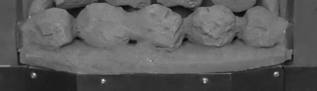
17 FUEL BED LAYOUT (PEBBLE) The following instruc ons detail how the ceramic fuel bed and loose components are to be installed onto the appliance. Great care should be taken when handling these ceramic parts as they are fragile and can easily be broken. Do not force any component into posi on, if it does not fit easily then you are not fi ng the part correctly. These instruc ons can also be followed to remove or reinstall the fuel bed a er cleaning. This is a procedure that can be undertaken by the customer as required and the frequency will be depend upon use. Step 1 Fit the fuel bed into the appliance as shown in the picture below. Step 2 Fit the front ceramic rail in front of the burner as shown in the picture below. 17

18 Step 3 Fit the two side cheeks into posi on as shown in the picture below. These are marked L and R for le and right hand. Step 4 Carefully place 2 large round pebbles from the bag marked A on the front row le and right posi ons. Place two oval pebbles from the bag marked B in the middle posi ons on to the fuel bed as shown in the picture below. 18

19 Step 5 Fit three oval pebbles from bag marked B into posi on as shown in the picture below. Step 6 Fit four small pebbles into posi on as shown in the picture below. 19


20 Manufacturer : Product Fiche Hearth Products Ltd Model No. F-011XX1 F-011XX2 Fuel Type Natural Gas I2H Natural Gas I2H Energy Efficiency Class F F Indirect Hea ng Func onality No No Direct Heat Output kw 3.2kW 3.2kW Indirect Heat Output kw N/A N/A EEI 43% 43% Useful Energy Efficiency (NCV) High : 52.3% High : 52.3% Useful Energy Efficiency (NCV) N/A N/A Nominal Heat Output High : 3.2kW High : 3.2kW Nominal Heat Output Low : 1.5kW Low : 1.3kW Heat Output Temperature Control Two Manual Stages Two Manual Stages Permanent Pilot Power (kw) N/A N/A Space Hea ng Emissions NOx (GCV) 130mg/kWh 130mg/kWh Product Fiche Manufacturer : Hearth Products Ltd Model No. F-X11XX1 F-X11XX2 Fuel Type Natural Gas I2H Natural Gas I2H Energy Efficiency Class F F Indirect Hea ng Func onality No No Direct Heat Output kw 3.5kW 3.5kW Indirect Heat Output kw N/A N/A EEI 49% 49% Useful Energy Efficiency (NCV) High : 57.9% High : 57.9% Useful Energy Efficiency (NCV) N/A N/A Nominal Heat Output High : 3.5kW High : 3.5kW Nominal Heat Output Low : 1.7kW Low : 1.4kW Heat Output Temperature Control Two Manual Stages Two Manual Stages Permanent Pilot Power (kw) N/A N/A Space Hea ng Emissions NOx (GCV) 130mg/kWh 130mg/kWh Important Note: The energy efficiency class of this product is defined using a seasonal efficiency calcula on which reduces the actual net efficiency of the product where the use of automated heat control, thermostats, window open sensors and mers are not used. This is not to be confused with the net efficiency, or useful efficiency of the appliance (shown in the tables above). This product MUST be installed by a Gas Safe Registered Installer. Full details are provided in this manual. Hearth Products Ltd. Unit 14 Tollgate Industrial Estate, Stafford, ST16 3SU 20
21 Part Number P-XX1101 P-XX1102 P-XX1103 P-XX1104 P-XX1105 P-XX1111 P-XX1112 P-XX1113 P-XX1114 P-XX1115 User Replaceable Parts Descrip on Ceramic Fuel Bed-Coal Ceramic Front Rail-Coal Ceramic Sidecheek LH-Coal Ceramic Sidecheek RH-Coal Ceramic Loose Fuel Pack-Coal Ceramic Fuel Bed Pebble Ceramic Front Rail Pebble Ceramic Sidecheek LH-Pebble Ceramic Sidecheek RH-Pebble Ceramic Loose Fuel Pack Pebble To order spare parts for your appliance visit or call us directly on It is important to note that the above spares are user serviceable components that can be changed by the customer. The spares shop also features other components which may have to be installed by a Gas Safe engineer. If in doubt please contact us directly. 21
22 22
23 Hearth Products Ltd Unit 14 Tollgate Industrial Estate, Stafford, ST16 3SU Tel: Fax: Due to our policy of con nual product improvement, some diagrams and small details may not be accurate however if there is any concern or ma er of understanding that you feel needs to be clarified please contact us directly. Our contact details are shown above. 23
FULL DEPTH HE GAS FIRE
 FULL DEPTH HE GAS FIRE USER INSTRUCTIONS INSTALLATION INSTRUCTIONS SERVICE INSTRUCTIONS It is a regulation that these instructions be handed to the customer after installation is complete. It is also the
BALANCED FLUE ROOM SEALED GAS FIRE
 BALANCED FLUE ROOM SEALED GAS FIRE USER INSTRUCTIONS INSTALLATION INSTRUCTIONS SERVICE INSTRUCTIONS Do not use this appliance if the front glass panel is broken, removed or fi ed incorrectly. It is a regula
Kalahari DECORATIVE FUEL EFFECT GAS FIRE
 Kalahari DECORATIVE FUEL EFFECT GAS FIRE User Instructions These instructions should be read by the user before operating the appliance and retained for future reference Model No. KRDC00MN & KRDC00SN are
Classic DECORATIVE FUEL EFFECT GAS FIRE. Installation, Maintenance & User Instructions
 Classic DECORATIVE FUEL EFFECT GAS FIRE Installation, Maintenance & User Instructions Hand these instructions to the user Model No s CSRC**MN is only for use on Natural Gas (G20) at a supply pressure of
EMBERGLOW CLASSIC RADIANT CONVECTOR GAS FIRE. Installation and Maintenance Instructions
 , EMBERGLOW CLASSIC RADIANT CONVECTOR GAS FIRE Installation and Maintenance Instructions Hand these instructions to the user Model No. FEMC00MN is for use on Natural Gas (G20) at a supply pressure of 20
INSET LIVE FUEL EFFECT GAS FIRE
 600B741/02 OWNER S GUIDE MODEL BR650 VA (GC No. 32-032-39) INSET LIVE FUEL EFFECT GAS FIRE THIS APPLIANCE IS FOR USE WITH NATURAL GAS (G20) WHEN CONVERTED USING CONVERSION KIT NO.591149 THIS APPLIANCE
(manual control) (ezi-slide control) INSET COAL EFFECT GAS CONVECTOR FIRE V1/100/B INSTALLATION & USER INSTRUCTIONS
 (ezi-slide control) INSET COAL EFFECT GAS CONVECTOR FIRE V1/100/B INSTALLATION & USER INSTRUCTIONS") Model Number: V1/100/A V1/100/B (manual control) (ezi-slide control) INSET COAL EFFECT GAS CONVECTOR FIRE INSTALLATION & USER INSTRUCTIONS GB IE SUITABLE FOR USE ON NATURAL GAS (G20) AT 20mbar SUPPLY PRESSURE
Model Number: V1/100/A V1/100/B (manual control) (ezi-slide control) INSET COAL EFFECT GAS CONVECTOR FIRE INSTALLATION & USER INSTRUCTIONS GB IE SUITABLE FOR USE ON NATURAL GAS (G20) AT 20mbar SUPPLY PRESSURE
PARAGON 2000 Xtra SLIDE CONTROL Owner's Book
 PARAGON 2000 Xtra SLIDE CONTROL Owner's Book INCLUDES USER, INSTALLATION & MAINTENANCE INSTRUCTIONS Please read these instructions carefully before you start using the appliance Keep this booklet handy
INSTALLATION & USER INSTRUCTIONS INSET DECORATIVE GAS FIRE
 INSTALLATION & USER INSTRUCTIONS INSET DECORATIVE GAS FIRE MODELS COVERED BY THESE INSTRUCTIONS HANNINGTON BRASS F500310 HANNINGTON BLACK F500311 Focal Point Fires plc. Christchurch, Dorset BH23 2BT Tel:
ENIGMA II SLIMLINE. Owner's Manual INCLUDES USER, INSTALLATION & MAINTENANCE INSTRUCTIONS
 ENIGMA II SLIMLINE Owner's Manual INCLUDES USER, INSTALLATION & MAINTENANCE INSTRUCTIONS Please read these instructions carefully before you start using the appliance Keep this booklet handy for future
STRATA BATTERY IGNITION RADIANT CONVECTOR GAS FIRE
 STRATA BATTERY IGNITION RADIANT CONVECTOR GAS FIRE Installation, Maintenance & User Instructions Hand these instructions to the user Model No s FORS**EN are for use on Natural Gas (G20) at a supply pressure
GB IE INSTALLATION & USER INSTRUCTIONS. Model Number: V1/300/B (ez-slide control) HIGH EFFICIENCY INSET COAL EFFECT GAS CONVECTOR FIRE
 HIGH EFFICIENCY INSET COAL EFFECT GAS CONVECTOR FIRE") Model Number: V1/300/B (ez-slide control) HIGH EFFICIENCY INSET COAL EFFECT GAS CONVECTOR FIRE INSTALLATION & USER INSTRUCTIONS GB IE SUITABLE FOR USE ON NATURAL GAS (G20) AT 20mbar SUPPLY PRESSURE These
Model Number: V1/300/B (ez-slide control) HIGH EFFICIENCY INSET COAL EFFECT GAS CONVECTOR FIRE INSTALLATION & USER INSTRUCTIONS GB IE SUITABLE FOR USE ON NATURAL GAS (G20) AT 20mbar SUPPLY PRESSURE These
GrateGlow THE ALL NEW CAPITAL COLLECTION. G20 at 20mbar convertible to G31 at 37mbar. For use in GB and le. Users Instructions
 GrateGlow A CARVER GROUP COMPANY --..--... THE GAS CONSUMERS' COUNCIL (GCC) IS AN INDEPENDENT ORGANISATION WHICH PROTECTS THE INTEREST OF GAS USERS. IF YOU NEED ADVICE, YOU WILL FIND THE TELEPHONE NUMBER
Emberglow COAL EFFECT BALANCED FLUE GAS FIRE
 Emberglow COAL EFFECT BALANCED FLUE GAS FIRE User Instructions These instructions should be read by the user before operating the appliance and retained for future reference Model No. FEBC00MN is only
Kalahari RC & Camber RC
 Kalahari RC & Camber RC DECORATIVE FUEL EFFECT GAS FIRE User Instructions These instructions should be read by the user before operating the appliance and retained for future reference Model No s KRDC**RN
ULTIMATE INSET LIVE FUEL EFFECT GAS FIRE MODEL 417 OWNER GUIDE
 ULTIMATE INSET LIVE FUEL EFFECT GAS FIRE MODEL 417 OWNER GUIDE THE NATURAL GAS MODEL IS FOR G20 AT A SUPPLY PRESSURE OF 20mbar THE PROPANE GAS MODEL IS FOR G31 AT A SUPPLY PRESSURE OF 37mbar THESE APPLIANCES
Owner s Manual INCLUDES. PARAGON 2016 & PARAGON 2016 Hi IMPORTANT
 Owner s Manual INCLUDES User, Maintenance, Service, and Installation Instructions PARAGON 2016 & PARAGON 2016 Hi Keep this booklet for service log and future reference IMPORTANT This appliance is guaranteed
Sonnet Plus Anthem Genesis Soraya
 5108617/01 OWNER GUIDE Sonnet Plus Anthem Genesis Soraya Model 746 (GC No. 32-032-57) INSET LIVE FUEL EFFECT GAS FIRE THIS APPLIANCE IS FOR USE WITH NATURAL GAS (G20) WHEN CONVERTED USING CONVERSION KIT
USE & MAINTENANCE INSTRUCTIONS FOR CHESNEYS ALCHEMY EVOLUTION PLUS GAS FIRES (NATURAL GAS ONLY) FOR DECORATIVE PURPOSES ONLY
 FOR DECORATIVE PURPOSES ONLY") CHESNEYS ALCHEMY EVOLUTION PLUS GAS FIRE by IMPORTANT NOTE Simulated coals, or simulated logs, together with simulated black bark, are supplied with this appliance. These are all manufactured from refractory
CHESNEYS ALCHEMY EVOLUTION PLUS GAS FIRE by IMPORTANT NOTE Simulated coals, or simulated logs, together with simulated black bark, are supplied with this appliance. These are all manufactured from refractory
Integra Convector Plus Manual
 Integra Convector Plus Manual Inset Live Fuel Effect Gas Fire Installation and Users Instructions These instructions should be read by the installer before installation and then should be handed to the
CLASSIC II QUATTRO DECORATIVE FUEL EFFECT APPLIANCES FOR USE WITH NATURAL GAS IIN INSTALLATION, SERVICING & USER INSTRUCTIONS
 CLASSIC II QUATTRO DECORATIVE FUEL EFFECT APPLIANCES FOR USE WITH NATURAL GAS IIN INSTALLATION, SERVICING & USER INSTRUCTIONS THESE INSTRUCTIONS MUST BE LEFT WITH THE USER MANUFACTURED BY: MULTIGLOW FIRES
Sonnet Plus Anthem Genesis Soraya
 5110524/01 OWNER GUIDE Sonnet Plus Anthem Genesis Soraya Model 747 (GC No. 32-032-51) INSET LIVE FUEL EFFECT GAS FIRE THIS APPLIANCE IS FOR USE WITH NATURAL GAS (G20) WHEN CONVERTED USING CONVERSION KIT
OWNER GUIDE. Model 750. INSET LIVE FUEL EFFECT GAS FIRE Fitted with Harmony, Avignon or Style fascia. (GC No )
") 5112499/01 OWNER GUIDE Model 750 INSET LIVE FUEL EFFECT GAS FIRE Fitted with Harmony, Avignon or Style fascia (GC No. 32-032-58) THIS APPLIANCE IS FOR USE WITH NATURAL GAS (G20) WHEN CONVERTED USING CONVERSION
5112499/01 OWNER GUIDE Model 750 INSET LIVE FUEL EFFECT GAS FIRE Fitted with Harmony, Avignon or Style fascia (GC No. 32-032-58) THIS APPLIANCE IS FOR USE WITH NATURAL GAS (G20) WHEN CONVERTED USING CONVERSION
ENIGMA II SLIDE CONTROL Owner's Book
 ENIGMA II SLIDE CONTROL Owner's Book INCLUDES USER, INSTALLATION & MAINTENANCE INSTRUCTIONS Please read these instructions carefully before you start using the appliance Keep this booklet handy for future
Orchestra COAL EFFECT BALANCED FLUE GAS FIRE
 Orchestra COAL EFFECT BALANCED FLUE GAS FIRE Installation and Maintenance Instructions Hand these instructions to the user Model No s FBFN76G & FBFN98G are for use on Natural Gas (G20) at a supply pressure
Kalahari DECORATIVE FUEL EFFECT GAS FIRE
 Kalahari DECORATIVE FUEL EFFECT GAS FIRE Installation and Maintenance Instructions Hand these instructions to the user Model No s KRDC00MN and KRDC00SN are for use on Natural Gas (G20) at a supply pressure
OWNER S GUIDE MODEL BR417 VA
 600B702/06 OWNER S GUIDE MODEL BR417 VA (G.C.32-032-07) Inset Live Fuel Effect Gas Fire with Ultimate Front AS SUPPLIED, THIS APPLIANCE IS FOR USE WITH NATURAL GAS (G20) WHEN CONVERTED USING VALOR CONVERSION
Dovre 250 Cast Iron Gas Stove
 Dovre 50 Cast Iron Gas Stove NATURAL GAS AND LPG INSTALLATION, SERVICING AND USER INSTRUCTIONS THIS PRODUCT IS FOR USE ONLY IN GREAT BRITAIN AND IRELAND These instructions are to be left with the customer,
COAL EFFECT BALANCED FLUE GAS FIRE
 Raglan COAL EFFECT BALANCED FLUE GAS FIRE Installation and Maintenance Instructions Hand these instructions to the user Model No. KBFC**MN for use on Natural Gas (G20) at a supply pressure of 20 mbar in
Full Depth Convector MC / SC
 Full Depth Convector MC / SC COAL EFFECT GAS FIRE Installation and Maintenance Instructions Hand these instructions to the user Model No s MICC**MN & MICC**SN are for use on Natural Gas (G20) at a supply
CRYSTAL FIRES. Inset Conventional Flue Fire. (BOSTON/MIAMI) Cf1 and MANHATTAN USER INSTALLATION AND SERVICING INSTRUCTIONS
 Cf1 and MANHATTAN USER INSTALLATION AND SERVICING INSTRUCTIONS") CRYSTAL FIRES (BOSTON/MIAMI) Cf1 and MANHATTAN Inset Conventional Flue Fire USER INSTALLATION AND SERVICING INSTRUCTIONS FOR USE WITH NATURAL GAS G20 @ 20 mbar For use in GB and IE CE THESE INSTRUCTIONS
CRYSTAL FIRES (BOSTON/MIAMI) Cf1 and MANHATTAN Inset Conventional Flue Fire USER INSTALLATION AND SERVICING INSTRUCTIONS FOR USE WITH NATURAL GAS G20 @ 20 mbar For use in GB and IE CE THESE INSTRUCTIONS
Owner s Manual INCLUDES. User, Maintenance, Service, and Installation Instructions Plus and 2000 Plus Extra Manual
 Owner s Manual INCLUDES User, Maintenance, Service, and Installation Instructions 2000 Plus and 2000 Plus Extra Manual Keep this booklet for service log and future reference IMPORTANT This appliance is
Windsor HE HIGH EFFICIENCY FUEL EFFECT GAS FIRE
 Windsor HE HIGH EFFICIENCY FUEL EFFECT GAS FIRE Installation, Maintenance & User Instructions Hand these instructions to the user Model No s FSHC**MN, FSHP**MN, FSHC**SN & FSHP**SN are for use on Natural
Melody Calypso PC COAL EFFECT GAS FIRE. Installation and Maintenance Instructions
 Melody Calypso PC COAL EFFECT GAS FIRE Installation and Maintenance Instructions Hand these instructions to the user Model No s FDRN45G, FDRN46G, FDRN57G, FDRN68G & FNRN42G are for use on Natural Gas (G20)
Castelle INSET FUEL EFFECT GAS FIRE. Hand these instructions to the user following installation
 Castelle INSET FUEL EFFECT GAS FIRE Installation, Maintenance & User Instructions Hand these instructions to the user following installation Model No s FPCL**RN is only for use on Natural Gas (G20) at
Model Apex Falcon, Titan & Zenit
 Model Apex Falcon, Titan & Zenit Installation and User Instructions All instructions must be handed to user for safekeeping This is not a DIY product and must be installed by a Gas Safe registered installer
OWNER GUIDE. Model 739 OPEN DECORATIVE GAS FIRE. (GC No )
") 5113426/01 OWNER GUIDE Model 739 OPEN DECORATIVE GAS FIRE (GC No. 32-032-54) THIS APPLIANCE IS FOR USE WITH NATURAL GAS (G20). WHEN CONVERTED USING CONVERSION KIT NO. 0595211 THIS APPLIANCE IS FOR USE
5113426/01 OWNER GUIDE Model 739 OPEN DECORATIVE GAS FIRE (GC No. 32-032-54) THIS APPLIANCE IS FOR USE WITH NATURAL GAS (G20). WHEN CONVERTED USING CONVERSION KIT NO. 0595211 THIS APPLIANCE IS FOR USE
INSTALLATION INSTRUCTIONS COMPACT GAS STOVE MODEL NUMBER 550
 INSTALLATION INSTRUCTIONS COMPACT GAS STOVE MODEL NUMBER 550 Before installation ensure that the local distribution conditions (identification of the type of gas and pressure) and the adjustment of the
Conventional Flue. Instructions for Installation. For use in NZ (New Zealand). IMPORTANT
. IMPORTANT") Logic HE Range Conventional Flue Instructions for Installation For use in NZ (New Zealand). IMPORTANT INSTALLATION AND SERVICING MUST ONLY BE CARRIED OUT BY AUTHORISED PERSONNEL. THE OUTER CASING, FRONT
Logic HE Range Conventional Flue Instructions for Installation For use in NZ (New Zealand). IMPORTANT INSTALLATION AND SERVICING MUST ONLY BE CARRIED OUT BY AUTHORISED PERSONNEL. THE OUTER CASING, FRONT
USE & MAINTENANCE INSTRUCTIONS FOR NU-FLAME EVOLUTION PLUS GAS EFFECT FIRES (NATURAL GAS & LPG) FOR DECORATIVE PURPOSES ONLY
 FOR DECORATIVE PURPOSES ONLY") Unit 4, Kimpton Trade & Business Centre Minden Road, Sutton, Surrey SM3 9PF Tel: 020 8254 6802 IMPORTANT NOTE Simulated coals, simulated pebbles, simulated logs, simulated driftwood or crushed rock manufactured
Unit 4, Kimpton Trade & Business Centre Minden Road, Sutton, Surrey SM3 9PF Tel: 020 8254 6802 IMPORTANT NOTE Simulated coals, simulated pebbles, simulated logs, simulated driftwood or crushed rock manufactured
BLACK KNIGHT 2 - Classic Collection
 BLACK KNIGHT 2 - Classic Collection Installation & Servicing Instructions (GC No. 32 170 16) IMPORTANT - THIS FIRE DOES NOT NORMALLY REQUIRE ADDITIONAL VENTILATION INTO THE ROOM IN WHICH IT IS INSTALLED
OWNER GUIDE. Anthem, Bolero, Camden, Minima, Victorian or Westminster fascia
 5114465/01 OWNER GUIDE Model 741 INSET LIVE FUEL EFFECT GAS FIRE Fitted with Anthem, Bolero, Camden, Minima, Victorian or Westminster fascia (GC No. 32-032-56) THIS APPLIANCE IS FOR USE WITH NATURAL GAS
OWNER S GUIDE ETERNITY. MODEL 540C (GC No ) INSET BALANCED FLUE GAS FIRE
 INSET BALANCED FLUE GAS FIRE") 600B637/02 ETERNITY MODEL 540C (GC No. 32-032-19) INSET BALANCED FLUE GAS FIRE THIS APPLIANCE IS FOR USE WITH NATURAL GAS (G20) THIS APPLIANCE IS FOR USE IN THE UNITED KINGDOM (GB) AND THE REPUBLIC OF
600B637/02 ETERNITY MODEL 540C (GC No. 32-032-19) INSET BALANCED FLUE GAS FIRE THIS APPLIANCE IS FOR USE WITH NATURAL GAS (G20) THIS APPLIANCE IS FOR USE IN THE UNITED KINGDOM (GB) AND THE REPUBLIC OF
Model BR660VA Heat Engine
 5112253/01 Model BR660VA Heat Engine POWER FLUE INSET GAS FIRE (GC No. 32-032-44) THIS APPLIANCE IS FOR USE WITH NATURAL GAS (G20). WHEN CONVERTED USING CONVERSION KIT NO. 0591149 THIS APPLIANCE IS FOR
USE & MAINTENANCE INSTRUCTIONS FOR NU-FLAME EVOLUTION PLUS GAS EFFECT FIRES (NATURAL GAS & LPG) FOR DECORATIVE PURPOSES ONLY
 FOR DECORATIVE PURPOSES ONLY") Unit 4, Kimpton Trade & Business Centre Minden Road, Sutton, Surrey SM3 9PF Tel: 020 8254 6802 IMPORTANT NOTE Simulated coals, simulated pebbles, simulated logs, simulated driftwood or crushed rock manufactured
Unit 4, Kimpton Trade & Business Centre Minden Road, Sutton, Surrey SM3 9PF Tel: 020 8254 6802 IMPORTANT NOTE Simulated coals, simulated pebbles, simulated logs, simulated driftwood or crushed rock manufactured
INSTALLATION & USERS INSTRUCTIONS. FOR USE WITH NATURAL GAS 20 mbar For use in GB and IE
 1 valentine s buildings Bechers drive Aintree racecourse Business Park L9 5ay CF1 L GAS APPLIANCE INSET CONVENTIONAL FLUED GAS FIRE INSTALLATION & USERS INSTRUCTIONS FOR USE WITH NATURAL GAS G20 @ 20 mbar
8 LITRE INSTANTANEOUS HOT WATER SYSTEM
 8 LITRE INSTANTANEOUS HOT WATER SYSTEM OPERATION GUIDE For customer service on this appliance: www.kickass.com.au/warranty GMK10498 Thank You! Thank you for choosing a KickAss KAHWSGAS8 8 LITRE INSTANTANEOUS
installation and user instructions
 installation and user instructions All instructions must be handed to user for safekeeping Revision A - 06/09 Country(s) of destination - GB/IE eko 00 fuel effect gas fire INSTALLATION INSTRUCTIONS Preliminary
5traxo INSTALLATION AND SERVICING INSTRUCTIONS MANDATORY REQUIREMENTS INSTALLATION
 5traxo Division of Legge Fabheat Ltd Longfield Road, Sydenham, Leamington Spa CV31 1XB Tel. (0926) 882233 Fax (0926) 450846 Registered in England No. 500091 Universal INSTALLATION AND SERVICING INSTRUCTIONS
Baxi Wentworth Classic Baxi Kingston 2 Classic
 Baxi Wentworth Classic Baxi Kingston 2 Classic Please leave these instructions with the user Live Fuel Effect Inset Gas Fires Comp N o 244609 - Iss 4 6/00 Installation and Servicing Instructions Page 2
Model 341 Black Beauty Slimline
 600B690/13 OWNER GUIDE Model 341 Black Beauty Slimline LIVE FUEL EFFECT GAS FIRE (GC No. 32-032-30) We trust that this guide gives sufficient details to enable this appliance to be operated and maintained
INSTALLATION, USERS AND SERVICING INSTRUCTIONS
 INSTALLATION, USERS AND SERVICING INSTRUCTIONS SLIMLINE (FAN FLUE) HOTBOX Inset Decorative coal or pebble effect Gas Fire For use with Natural Gas (G20) @ 20mbar or Butane (G30) @ 28mbar or Propane (G31)
Napoli BF COAL EFFECT BALANCED FLUE GAS FIRE
 Napoli BF COAL EFFECT BALANCED FLUE GAS FIRE Installation, Maintenance & User Instructions Hand these instructions to the user Model No. ABFC**MN2 & ABFC**EN3 are for use on Natural Gas (G20) at a supply
THIS PRODUCT IS APPROVED TO THE EUROPEAN GAS APPLIANCE DIRECTIVE
 Solar Crown and Cast Inset Fires Installation Instructions THIS APPLIANCE MUST BE INSTALLED/SERVICED BY A COMPETENT PERSON IN ACCORDANCE WITH ALL THE REGULATIONS IN FORCE THIS PRODUCT IS APPROVED TO THE
Mesina Fires GLASS FRONT VENTED Model No. M 70
 Mesina Fires GLASS FRONT VENTED Model No. M 70 DECORATIVE COAL EFFECT NATURAL VENT GAS FIRE User Instructions These instructions should be read by the user before operating the appliance and retained for
MODEL 466 Radiant / Convector Gas Fire Black Beauty
 O W N E R G U I D E MODEL 466 Radiant / Convector Gas Fire Black Beauty This Owner Guide is intended to help you care for your Valor gas fire. Please read carefully before using your gas fire and keep
Kenilworth HE, Linear HE, Diamond HE & Expression HE
 Kenilworth HE, Linear HE, Diamond HE & Expression HE INSET LIVE FUEL EFFECT GAS FIRE Installation, Maintenance & User Instructions Hand these instructions to the owner following installation, they must
Rivas Plus INSET LIVE FUEL-EFFECT GAS FIRES. Hand these instructions to the owner following installation, they must be retained for future reference.
 Rivas Plus INSET LIVE FUEL-EFFECT GAS FIRES Installation, Maintenance & User Instructions. Hand these instructions to the owner following installation, they must be retained for future reference. Model
CRYSTAL FIRES VALENTINES BUILDING BECHERS DRIVE AINTREE RACECOURSE BUSINESS PARK LIVERPOOL MERSEYSIDE L9 5AY HEATRAVE S/L DECORATIVE INSET GAS FIRE
 CRYSTAL FIRES VALENTINES BUILDING BECHERS DRIVE AINTREE RACECOURSE BUSINESS PARK LIVERPOOL MERSEYSIDE L9 5AY HEATRAVE S/L DECORATIVE INSET GAS FIRE THIS APPLIANCE IS CAT I2H FOR USE WITH NATURAL GAS ONLY
E-Studio TM & E-Box TM
 E-Studio TM & E-Box TM Conventional Flue with Upgradeable Control Valve E-box E-Studio Instructions for Use, Installation & Servicing For use in GB & IE (Great Britain & Republic of Ireland). IMPORTANT
PARAGON SIESTA PLUS. Remote Control
 PARAGON SIESTA PLUS Remote Control OWNER'S MANUAL INCLUDES USER, INSTALLATION & MAINTENANCE INSTRUCTIONS Please read these instructions carefully before you start using the appliance Keep this booklet
VFC Convector Pebble Effect Fires With upgradeable control valve
 VFC Convector Pebble Effect Fires With upgradeable control valve Instructions for Use, Installation and Servicing For use in GB, IE (Great Britain and Eire) This appliance has been certified for use in
Logic Hotbox & Convector Fire
 Logic Hotbox & Convector Fire Instructions for Use, Installation and Servicing For use in GB, IE (Great Britain and Republic of Ireland) IMPORTANT THIS PRODUCT HAS A NAKED FLAME. IT IS IMPORTANT TO ENSURE
Plus Model BR645 VA (G.C )
") 600B656/05 Plus Model BR645 VA (G.C. 32-032-34) As supplied, this appliance is for use with natural gas (G20) When converted using conversion kit no. 591149 this appliance is for use with propane gas (G31)
600B656/05 Plus Model BR645 VA (G.C. 32-032-34) As supplied, this appliance is for use with natural gas (G20) When converted using conversion kit no. 591149 this appliance is for use with propane gas (G31)
BALLADE BALANCED FLUE CONVECTOR FIRE
 BALLADE BALANCED FLUE CONVECTOR FIRE MODEL No VBFC 16NG GAS COUNCIL NO. 32-234-14 THIS IS NOT A DO IT YOURSELF PRODUCT THIS APPLIANCE MUST BE INSTALLED BY A CORGI REGISTERED PERSON INSTALLATION, SERVICING
VFC Radiant & Convector
 VFC Radiant & Convector Fire Range With Upgradeable Control Valve Instructions for Use, Installation and Servicing For use in GB, IE (Great Britain and Republic of Ireland) IMPORTANT THIS PRODUCT HAS A
INSTALLER GUIDE COALFLAME & LIMOUSIN. MODEL BR627 (GC No ) INSET LIVE FUEL EFFECT GAS FIRE
 INSET LIVE FUEL EFFECT GAS FIRE") 600B607/05 INSTALLER GUIDE COALFLAME & LIMOUSIN MODEL BR627 (GC No. 32-032-22) INSET LIVE FUEL EFFECT GAS FIRE AS SUPPLIED, THIS APPLIANCE IS FOR USE WITH NATURAL GAS (G20) WHEN CONVERTED USING VALOR CONVERSION
600B607/05 INSTALLER GUIDE COALFLAME & LIMOUSIN MODEL BR627 (GC No. 32-032-22) INSET LIVE FUEL EFFECT GAS FIRE AS SUPPLIED, THIS APPLIANCE IS FOR USE WITH NATURAL GAS (G20) WHEN CONVERTED USING VALOR CONVERSION
C&J DGT5000 Suite Shelf or Slab Burner. Owner's Book
 C&J DGT5000 Suite Shelf or Slab Burner Owner's Book (THIS APPLIANCE IS FITTED WITH ALKALINE BATTERIES) INCLUDES USER, INSTALLATION & MAINTENANCE INSTRUCTIONS Please read these instructions carefully before
Marlborough & Stockton
 Marlborough & Stockton Conventional Flue Coal Effect Stove With Upgradeable Control Valve Instructions for Use, Installation & Servicing For use in GB & IE (Great Britain & Republic of Ireland). IMPORTANT
Classic II NG. Decorative fuel effect appliances for use with Natural Gas. Installation, Servicing & User Instructions
 Classic II NG Decorative fuel effect appliances for use with Natural Gas Installation, Servicing & User Instructions THESE INSTRUCTIONS TO BE LEFT WITH THE USER Canterbury Road, St. Nicholas-at-Wade, Nr.
Model 741FS. Dream, Heritage or Opulent OWNER GUIDE. INSTALLER: Please leave this guide with the owner Baxi Heating U.K. Limited 2007.
 5112500/02 Model 741FS Inset live fuel effect gas fire Incorporating the BAXI FIRES DIVISION CONTROL Fitted with one of the following fascia. Dream, Heritage or Opulent (GC No. 32-032-56) We trust that
RADIANT / CONVECTOR GAS FIRE MODEL 426 (GC ) INSTALLATION & SERVICING INSTRUCTIONS INSTALLER: Please leave these instructions with the owner
 INSTALLATION & SERVICING INSTRUCTIONS INSTALLER: Please leave these instructions with the owner") THIS APPLIANCE IS FOR USE WITH NATURAL GAS (G20) AT A SUPPLY PRESSURE OF 20mbar (8in w.g.) THIS APPLIANCE IS FOR USE IN THE UNITED KINGDOM (GB) AND THE REPUBLIC OF IRELAND (IE) RADIANT / CONVECTOR GAS
THIS APPLIANCE IS FOR USE WITH NATURAL GAS (G20) AT A SUPPLY PRESSURE OF 20mbar (8in w.g.) THIS APPLIANCE IS FOR USE IN THE UNITED KINGDOM (GB) AND THE REPUBLIC OF IRELAND (IE) RADIANT / CONVECTOR GAS
Baxi Wentworth Deluxe Baxi Kingston 2 Deluxe
 Baxi Wentworth Deluxe Baxi Kingston 2 Deluxe Please leave these instructions with the user Live Fuel Effect Inset Gas Fires Comp N o 244621 - Iss 5 6/00 Installation and Servicing Instructions Page 2 Natural
GB IE. VALOR BOLERO (MODEL BR626) Inset Decorative Fuel Effect Gas Fires. For
 Inset Decorative Fuel Effect Gas Fires. For") O W N E R G U I D E For VALOR BOLERO (MODEL BR626) Inset Decorative Fuel Effect Gas Fires GB IE This Owner Guide is intended to help you care for your Valor gas fire. Please read carefully before using
O W N E R G U I D E For VALOR BOLERO (MODEL BR626) Inset Decorative Fuel Effect Gas Fires GB IE This Owner Guide is intended to help you care for your Valor gas fire. Please read carefully before using
Richmond Plus INSET LIVE FUEL-EFFECT GAS FIRES. Hand these instructions to the user after installation.
 Richmond Plus INSET LIVE FUEL-EFFECT GAS FIRES Installation, Maintenance & User Instructions. Hand these instructions to the user after installation. Model No s FOPC**MN, FOPC**SN & FOPC**RN are for use
Clarendon & Ashdon. Conventional Flue Log Effect Stove Range. With Upgradeable Control Valve. Instructions for Use, Installation & Servicing
 Clarendon & Ashdon Conventional Flue Log Effect Stove Range With Upgradeable Control Valve Instructions for Use, Installation & Servicing For use in GB & IE (Great Britain & Republic of Ireland). IMPORTANT
RENOIR RADIANT CONVECTOR GAS FIRE
 RENOIR RADIANT CONVECTOR GAS FIRE Installation, Maintenance & User Instructions Hand these instructions to the user Model No. s FRECN0EN, FRECR0EN, FRECN0RN2 & FRECR0RN2 are for use on Natural Gas (G20)
Marlborough & Stockton Coal Effect Stove Range
 Marlborough & Stockton Coal Effect Stove Range Conventional Flue With upgradeable control valve Instructions for Use, Installation and Servicing For use in GB, IE (Great Britain and Eire) IMPORTANT This
PARAGON FOCUS HE MULTI - FLUE SLIDE CONTROL
 PARAGON FOCUS HE MULTI - FLUE SLIDE CONTROL OWNER MANUAL INCLUDES USER INSTRUCTION & INSTALLATION & MAINTENANCE INSTRUCTIONS Please read these instructions carefully before you start installing or using
PARAGON ONE REMOTE Owner's Book
 PARAGON ONE REMOTE Owner's Book (THIS APPLIANCE IS FITTED WITH ALKALINE BATTERIES) INCLUDES USER, INSTALLATION & MAINTENANCE INSTRUCTIONS Please read these instructions carefully before you start using
morsø PANTHER GAS STOVE
 morsø PANTHER GAS STOVE MODEL No. 553 OWNER S GUIDE This appliance meets the requirements of the European Gas Directive This guide is intended to help you care for your morsø gas stove. It gives sufficient
Conventional Flue Coal Effect Stove. With upgradeable control valve. Instructions for Use, Installation and Servicing
 Yeoman Exe Midi Conventional Flue Coal Effect Stove With upgradeable control valve Instructions for Use, Installation and Servicing For use in GB, IE (Great Britain and Eire) IMPORTANT This product contains
Caress HE COAL EFFECT HIGH EFFICIENCY GAS FIRE
 Caress HE COAL EFFECT HIGH EFFICIENCY GAS FIRE Installation, Maintenance & User Instructions Hand these instructions to the owner following installation, they must be retained for future reference. Model
INSTALLER S GUIDE. MODEL 639 Open Decorative Gas Fire
 3002369/03 INSTALLER S GUIDE MODEL 639 Open Decorative Gas Fire (G.C No. 32-032-47) THIS APPLIANCE IS FOR USE WITH NATURAL GAS (G20) WHEN CONVERTED USING CONVERSION KIT NO. 0591301 THIS APPLIANCE IS FOR
ARIES AURA BLENHEIM STYLE
 ARIES AURA BLENHEIM STYLE FULL DEPTH GAS FIRE INSTALLATION AND USER INSTRUCTIONS All instructions must be handed to user for safekeeping Revision A - 05/05 Country(s) of destination - GB/IE Focal Point
NIGMA. Fuel Effect Gas Fire INSTALLATION, SERVICING AND USER INSTRUCTIONS. All instructions must be handed to the user for safekeeping
 Σ NIGMA Fuel Effect Gas Fire INSTALLATION, SERVICING AND USER INSTRUCTIONS All instructions must be handed to the user for safekeeping Revision A 09/03 Country(s) of destination: GB, IE Focal Point Fires
INSTALLATION & USER INSTRUCTIONS
 INSTALLATION & USER INSTRUCTIONS STONE EFFECT DECORATIVE GAS FIRE MODELS COVERED BY THESE INSTRUCTIONS POLARIS GB IE Focal Point Fires plc. Christchurch, Dorset BH23 2BT Tel: 01202 499330 Fax: 01202 499326
OWNER GUIDE. Sunfire II Radiant. Radiant / Convector Gas Fire. Model 347 (G. C. Number )
") 5110946/01 OWNER GUIDE Sunfire II Radiant Radiant / Convector Gas Fire Model 347 (G. C. Number 32-032-62) THIS APPLIANCE IS FOR USE WITH NATURAL GAS (G20) THIS APPLIANCE IS SUITABLE ONLY FOR INSTALLATION
5110946/01 OWNER GUIDE Sunfire II Radiant Radiant / Convector Gas Fire Model 347 (G. C. Number 32-032-62) THIS APPLIANCE IS FOR USE WITH NATURAL GAS (G20) THIS APPLIANCE IS SUITABLE ONLY FOR INSTALLATION
Decorative Fuel Effect Appliances
 Decorative Fuel Effect Appliances Technical Manual User and Installation Instructions for CUBB22US Available in Natural Gas. 1 Contents Section Pages 1 Unpacking 3 2 Installation Parameters 4 3 Installation
SLIMLINE RADIANT GAS FIRE
 SLIMLINE RADIANT GAS FIRE FOR USE WITH CHLOE - JULIET - NEW WAVE - HEAT WAVE ANNABELLE - ZARA - CARMEN - CARMEN HIW INSTALLATION AND USER INSTRUCTIONS All instructions must be handed to user for safekeeping
VFC Radiant & Convector Fire Range With upgradeable control valve
 VFC Radiant & Convector Fire Range With upgradeable control valve Instructions for Use, Installation and Servicing For use in GB, IE (Great Britain and Eire) This appliance has been certified for use in
ENIGMA HE Remote Control
 ENIGMA HE Remote Control OWNERS MANUAL INCLUDES USER INSTRUCTIONS & INSTALLATION & MAINTENANCE INSTRUCTIONS Please read these instructions carefully before you start installing or using this appliance
Dovre 280. Conventional Flue Log Effect Stove. With Upgradeable Control Valve. Instructions for Use, Installation and Servicing
 Dovre 280 Conventional Flue Log Effect Stove With Upgradeable Control Valve Instructions for Use, Installation and Servicing For use in GB, IE (Great Britain and Republic of Ireland) IMPORTANT THE OUTER
Huntingdon 20/30/40. Conventional Flue Log Effect Stove. With Upgradeable Control Valve. Instructions for Use, Installation and Servicing
 Huntingdon 20/30/40 Conventional Flue Log Effect Stove With Upgradeable Control Valve Instructions for Use, Installation and Servicing For use in GB, IE (Great Britain and Republic of Ireland) IMPORTANT
Clarendon and Ashdon Coal Effect Stove Range Conventional Flue
 Clarendon and Ashdon Coal Effect Stove Range Conventional Flue With upgradeable control valve Instructions for Use, Installation and Servicing For use in GB, IE (Great Britain and Eire) IMPORTANT THE OUTER
THESE INSTRUCTIONS TO BE LEFT WITH THE END USER
 RIBBON BURNER DECORATIVE FUEL EFFECT APPLIANCES FOR USE WITH NATURAL GAS INSTALLATION, SERVICING & USER INSTRUCTIONS THESE INSTRUCTIONS TO BE LEFT WITH THE END USER Multiglow Fires St Nicholas - at Wade
FIRECHARM LF ELECTRONIC
 987618 Issue 5 FIRECHARM LF ELECTRONIC RADIANT/CONVECTOR GAS FIRE BRONZE (G.C. No. 32 689 32) BLACK (G.C. No. 32 689 33) Installation and Servicing Instructions THIS APPLIANCE IS FOR USE WITH NATURAL GAS
installation and user instructions
 installation and user instructions All instructions must be handed to user for safekeeping Revision A - 06/09 Country(s) of destination - GB/IE eko 3030 eko 3035 eko 3040 eko 3050 eko 3060 eko 3065 fuel
INSTALLATION & USER INSTRUCTIONS
 INSTALLATION & USER INSTRUCTIONS INSET DECORATIVE GAS FIRE MODELS COVERED BY THESE INSTRUCTIONS eko 2050 Christchurch, Dorset BH23 2BT Tel: 01202 588 638 Fax: 01202 499 639 www.ekofires.co.uk e-mail: sales@ekofires.co.uk
OWNER GUIDE MODEL BR622 (GC ) INSET LIVE FUEL EFFECT GAS FIRE INCORPORATING. WITH ADORN, VISAGE, ELEGANT or ICON Front
 INSET LIVE FUEL EFFECT GAS FIRE INCORPORATING. WITH ADORN, VISAGE, ELEGANT or ICON Front") '19 act 2000 6008624/01 May 2000 OWNER GUIDE MODEL BR622 (GC32-032 - 09) INSET LIVE FUEL EFFECT GAS FIRE INCORPORATING THE ~ VALOR FireSl~'deCONTROL (E WITH ADORN, VISAGE, ELEGANT or ICON Front THIS APPLIANCE
'19 act 2000 6008624/01 May 2000 OWNER GUIDE MODEL BR622 (GC32-032 - 09) INSET LIVE FUEL EFFECT GAS FIRE INCORPORATING THE ~ VALOR FireSl~'deCONTROL (E WITH ADORN, VISAGE, ELEGANT or ICON Front THIS APPLIANCE