CONSERVER INSTALLATION, OPERATION, AND SERVICE MANUAL CONSERVER XL2 DISHMACHINES. Conserver XL2 Manual T
|
|
|
- Gyles Simmons
- 6 years ago
- Views:
Transcription


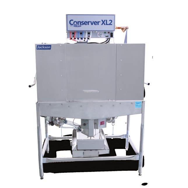


1 INSTALLATION, OPERATION, AND SERVICE MANUAL CONSERVER XL2 DISHMACHINES CONSERVER Conserver XL2 Manual
2
3 MANUFACTURER'S WARRANTY ONE YEAR LIMITED PARTS AND LABOR WARRANTY ALL NEW JACKSON DISHWASHERS ARE WARRANTED TO THE ORIGINAL PURCHASER TO BE FREE FROM DEFECTS IN MATERIAL OR WORKMANSHIP, UNDER NORMAL USE AND OPERATION, FOR A PERIOD OF (1) ONE YEAR FROM DATE OF PURCHASE, BUT IN NO EVENT TO EXCEED (18) EIGHTEEN MONTHS FROM DATE OF SHIPMENT FROM THE FACTORY. Jackson WWS agrees under this warranty to repair or replace, at its discretion, any original part which fails under normal use due to faulty material or workmanship during the warranty period, providing the equipment has been unaltered, and has been properly installed, maintained, and operated in accordance with the applicable factory instruction manual and failure is reported to an authorized service agency within the warranty period. This includes the use of factory-specified genuine replacement parts, purchased directly from a Jackson-authorized parts distributor or service agency. Use of generic replacement parts may create a hazard and void warranty certification. The labor to repair or replace such failed part will be paid by Jackson WWS, within the continental United States, Hawaii, and Canada, during the warranty period provided a Jackson WWS authorized service agency, or those having prior authorization from the factory, performs the service. Any repair work by persons other than a Jackson WWS authorized service agency is the sole responsibility of the customer. Labor coverage is limited to regular hourly rates; overtime premiums and emergency service charges will not be paid by Jackson WWS. Accessory components not installed by the factory carry a (1) one year parts warranty only. Accessory components such as table limit switches, pre-rinse units, etc. that are shipped with the unit and installed at the site are included. Labor to repair or replace these components is not covered by Jackson WWS. This warranty is void if failure is a direct result from shipping, handling, fire, water, accident, misuse, acts of God, attempted repair by unauthorized persons, improper installation, if serial number has been removed or altered, or if unit is used for a purpose other than originally intended. TRAVEL LIMITATIONS Jackson WWS limits warranty travel time to (2) two hours and mileage to (100) one-hundred miles. Jackson WWS will not pay for travel time and mileage that exceeds this, or any additonal fees such as those for air or boat travel without prior authorization. WARRANTY REGISTRATION To register your product, go to or call Failure to register your product will void the warranty. REPLACEMENT PARTS WARRANTY Jackson replacement parts are warranted for a period of (90) ninety days from date of installation or (180) one-hundred-eighty days from the date of shipment from the factory, whichever occurs first. PRODUCT CHANGES AND UPDATES Jackson WWS reserves the right to make changes in the design and specification of any equipment as engineering or necessity requires. THIS IS THE ENTIRE AND ONLY WARRANTY OF JACKSON WWS. JACKSON S LIABILITY ON ANY CLAIM OF ANY KIND, INCLUDING NEGLIGENCE, WITH RESPECT TO THE GOODS OR SERVICES COVERED HEREUNDER, SHALL IN NO CASE EXCEED THE PRICE OF THE GOODS OR SERVICES OR PART THEREOF WHICH GIVES RISE TO THE CLAIM. THERE ARE NO WARRANTIES, EXPRESSED OR IMPLIED, INCLUDING FOR FITNESS OR MERCHANTABILITY, THAT ARE NOT SET FORTH HEREIN, OR THAT EXTEND BEYOND THE DURATION HEREOF. UNDER NO CIRCUMSTANCES WILL JACKSON WWS BE LIABLE FOR ANY LOSS OR DAMAGE, DIRECT OR CONSEQUENTIAL, OR FOR DAMAGES IN THE NATURE OF PENALTIES, ARISING OUT OF THE USE OR INABILITY TO USE ANY OF ITS PRODUCTS. ITEMS NOT COVERED THIS WARRANTY DOES NOT COVER CLEANING OR DELIMING OF THE UNIT OR ANY COMPONENT SUCH AS, BUT NOT LIMITED TO, WASH ARMS, RINSE ARMS, OR STRAINERS AT ANYTIME. NOR DOES IT COVER ADJUSTMENTS SUCH AS, BUT NOT LIMITED TO, TIMER CAMS, THERMOSTATS, OR DOORS BEYOND (30) THIRTY DAYS FROM THE DATE OF INSTALLATION. IN ADDITION, THE WARRANTY WILL ONLY COVER REPLACEMENT WEAR ITEMS SUCH AS CURTAINS, DRAIN BALLS, DOOR GUIDES, OR GASKETS DURING THE FIRST (30) THIRTY DAYS AFTER INSTALLATION. ALSO, NOT COVERED ARE CONDITIONS CAUSED BY THE USE OF INCORRECT (NON-COMMERICAL) GRADE DETERGENTS, INCORRECT WATER TEMPERATURE OR PRESSURE, OR HARD WATER CONDITIONS.
4 REVISION HISTORY Revision Letter Revision Date Made by Applicable ECNs Details F MAW 7040 Added new logo. Changed to new layout. Added new parts for the redesigned Conserver XL unit. G MAW N/A Added instructions and schematics for use with universal timers. H MAW 7107, 7257, 7478, 7293, 7553, 7122, 7447, 7559, 7258, 7518 Converted to centered layout with bottom date stamp for revisions. Combined installation and technical manuals. Added bowl option and new style control box for universal timers. Combined installation & service manuals into one: obsolete I/O manual I ARL N/A Corrected shim kit part number on pg. 57. J RLC 8226 Made Buzzers optional. K RLC QOF 386 Updated parts. L RLC QOF NBD- 219 Update Manufacturer Information. Updated Pump assembly view. M RLC 8271 Added magnet cover. N KAP 8305 Updated P/N on pg. 54. O KAP N/A Removed part on pg. 50. Corrected P/N pg. 50. Updated part on pg. 52. P KAP QOF 386 Updated P/N 8 and 8a on pg and Q JH 8369 Removed the XL, AXL, AXL2, AXL2-CML, and AXL2-CMR units from the manual. Changed Hood and Controls on the XL2 to new design. Removed list of Service Repair Centers. Updated the Hood Assembly, pg. 35. Removed references to old/new styles and parts associated with the old style. Removed 60 Hz motor assembly from pg.45. Changed P/Ns of 60 Hz motor assembly and parts on pg. 46. Added new 3/4 plumbing, new air-gap, and new air-gap insert to pg. 42. Removed vacuum breaker repair kit from pg. 44. R JH S JH N/A T JH N/A Changed timer from to Added Delay Timer and Delay Timer Cover to Control Box. Audited manual and corrected all incorrect P/Ns. Complete update of the manual to new format. Corrected Cantilever Arm part number. Added 115 V Chemical Feeder Pump Assemblies to the Control Box pages. Removed assembly numbers from Chemical Feeder Pump Components page and referenced Control Box pages. Changed picture of machine on the cover. Removed references to optional machine cycles. ii

5 NOMENCLATURE Conserver XL2 Series Conserver XL2 Low-temperature, chemical-sanitizing, dual-rack dishmachine. Conserver XL2-CML Low-temperature, chemical-sanitizing, dual-rack dishmachine with left-hand feed-through. Conserver XL2-CMR Low-temperature, chemical-sanitizing, dual-rack dishmachine with right-hand feed-through. Conserver XLS Solid Dispenser Option. The manufacturer provides technical support for all of the dishmachines detailed in this manual. We strongly recommend that you refer to this manual before making a call to our technical support staff. Please have this manual open when you call so that our staff can refer you, if necessary, to the proper page. Technical support is not available on holidays. Contact technical support toll free at Technical support is available for service personnel only. iii
6 TABLE OF CONTENTS GUIDES Symbols...1 Abbreviations & Acronyms...1 SPECIFICATIONS XL2 Dimensions...2 XL2-CML Dimensions...3 XL2-CMR Dimensions...4 XLS Solid Dispenser Option...5 Table Dimensions...6 Operating Capacities...7 Electrical Requirements...8 INSTALLATION Installation Instructions... 9 Inspection... 9 Unpacking... 9 Leveling... 9 Plumbing... 9 Pressure Regulator Shock Absorber Drain Line Plumbing Check Electrical Power Connections...11 Thermostats...11 Voltage Check Preparing Chemical Pumps Priming Chemical Pumps Timer Change CAM Timer Operation False Panel OPERATION Operating Instructions Preparation Power Up Filling the Wash Tub First Rack Ware Preparation Washing a Rack of Ware Operational Inspection Shutdown and Cleaning Deliming iv
7 TABLE OF CONTENTS MAINTENANCE Preventative Maintenance TROUBLESHOOTING Common Problems PARTS XL2 Control Box XLS Solid Dispenser Option Chemical Feeder Pump Components XL2 Hood Assembly Cantilever Arm Tub Assembly Left-front Tub Assembly Right-front Frame Assembly Wash Motors /4 Inlet Plumbing Assembly /4 Solenoid Valve Repair Kit /2 Inlet Plumbing Assemby Plumbing Options Wash Manifold Assembly Miscellaneous Parts SCHEMATICS XLS 115 V, 60 Hz, Single-phase...52 XL2 115 V, 60 Hz, Single-phase...53 XL2-CML/CMR 115 V, 60 Hz, Single-phase...54 XL V, 60 Hz, Single-phase...55 XL V, 50 Hz, Single-phase...56 v1
8 GUIDES GUIDES SYMBOLS! WARNING - risk of injury to personnel.! CAUTION - risk of damage to equipment. - risk of electrical shock. - caustic chemicals. i - reference data plate. - lockout electrical power. NOTICE - important note. ABBREVIATIONS & ACRONYMS ANSI - American National Standards Institute CFM - Cubic Feet per Minute GHT - Garden Hose Thread GPH - Gallons per Hour GPM - Gallons per Minute GPG - Grains per Gallon HP - Horse Power Hz - Hertz ID - Inside Diameter kw - Kilowatts LPM - Liters per Minute NFPA - National Fire Protection Association NPT - National Pipe Thread PSI - Pounds per Square Inch V - Volts 1
9 SPECIFICATIONS XL2 DIMENSIONS B 2 [52mm] 4 [102mm] [286mm] 25 [636mm] B 44 [1117mm] 78 [1981 mm] [1453mm] LEGEND: A - Electrical connection B - Water inlet 1/2" NPT I.P.S C - Drain connection 2" NPT I.P.S [1658mm] All dimensions from the floor can be increased 1/2" All vertical using the dimensions machine's are adjustable +/- 1/2" from feet. floor due to adjustable bullet feet. C [1286mm] 13 [330 mm] A [387mm] [171mm] [438mm] MAXIMUM DISH CLEARANCE [1740mm] 34 [864mm] [283mm] C 2
10 SPECIFICATIONS SECTION 1: SPECIFICATION INFORMATION CONSERVER XL2-CML DIMENSIONS XL2-CML DIMENSIONS LEGEND: A - Electrical connection B - Water inlet 1/2" NPT I.P.S C - Drain connection 2" NPT I.P.S B 78 [1981mm] All dimensions from the floor can be increased All vertical dimensions are +/- 1/2" from floor 1/2" using the machine's adjustable feet. due to adjustable bullet feet [1658mm] B [295mm] 4 [102mm] [337mm] A 25 [635mm] C 13 [330mm] 44 [1118mm] 48 1/2 [1232MM] A [387mm] 6 3/4 [171 mm] [438mm] MAXIMUM DISH CLEARANCE 68 1/2 [1740 mm] 34 [864mm] C 11 1/4 [283 mm] Conserver XL2 Manual Q Issued: Revised:
11 SPECIFICATIONS SECTION 1: SPECIFICATION INFORMATION CONSERVER XL2-CMR DIMENSIONS XL2-CMR DIMENSIONS LEGEND: A - Electrical connection B - Water inlet 1/2" NPT I.P.S C - Drain connection 2" NPT I.P.S B All dimensions vertical dimensions from the floor are can +/- be 1/2" increased from floor 1/2" due using to adjustable the machine's bullet adjustable feet. feet. 78 [1981mm] [1658mm] B [295mm] 4 [102mm] [635mm] [337mm] A C 13 [330mm] 44 [1118mm] 48 1/2 [1232mm] A [387mm] 6 3/4 [171mm] 68 1/2 [1740mm] [438mm] MAXIMUM DISH CLEARANCE 34 [864mm] C 11 1/4 [283mm] Conserver XL2 Manual Q Issued: Revised:
12 SPECIFICATIONS XLS SOLID DISPENSER OPTION SECTION 1: SPECIFICATION INFORMATION CONSERVER XLS BOWL OPTION Legend A - Electrical Connection B - Water Connection, 1 4" [545mm] 18 [459mm] Bowl Option - Front Side View 8 [202mm] A 1 2 [13mm] B 5 [128mm] [134mm] Bowl Option - Right Side View Conserver XL2 Manual Q Issued: Revised:
13 SPECIFICATIONS TABLE DIMENSIONS Table Dimensions Corner Installation 20 1/2" Opening 25 1/4" 2 1/2" 4" Min. Table Dimensions Connection to Dishmachine 2 1/4" 4" Min. 20 1/2" Opening 25 1/4" 3/4" 1 1/2" Roll 20 1/2" Table Dimensions Straight-through Installation 25 1/4" 20 1/2" Opening 4" Min. 2 1/2" FRONT 25 1/4" 6
14 SPECIFICATIONS Model Designation: OPERATING CAPACITIES XL2 Operating Capacity: Racks per Hour 74 Dishes per Hour 1850 Glasses per Hour 2664 Tank Capacity: Wash Tank (gallons) 3.1 Wash Tank (liters) 11.7 Wash Pump Capacity: GPM 61 LPM 231 Electrical Loads (as applicable): Wash Motor HP 1.0 Operating Times (seconds): Wash 53 Rinse 14 Dwell 20 Total Cycle Time 87 NOTICE Always refer to the machine data plate for specific electrical and water requirements. The material provided in this manual is for reference only and is subject to change without notice. Water Temperatures ( F): Wash Temperature (minimum/recommended) 120/140 Rinse Temperature (minimum/recommended) 120/140 Inlet Temperature (minimum/recommended) 120/140 Other Water Requirements: Water Flow Pressure (PSI) 20 +/- 5 GPH Water Line Size (NPT) 3/4 Drain Line Size (NPT) 2 Minimum Chlorine Required (PPM) 50 7
15 SPECIFICATIONS ELECTRICAL REQUIREMENTS NOTICE i All electrical ratings provided in this manual are for reference only. Always refer to the machine data plate to get exact electrical information for this machine. All electrical work performed on machines should be done in accordance with applicable local, state, territorial, and national codes. Work should only be performed by qualified electricians and authorized service agents. Note that all electrical wiring used in this series of machines must be rated, at a minimum, for 212 F (100 C), and that only copper conductors must be used. Where applicable, heating element amperage draws have been adjusted for the assumed input voltage. The manufacturer assumes incoming voltages will be either 115, 208, 230, or 460 Volts. Some heating elements used in the machines are rated for other voltages, such as 240 Volts and 480 Volts. Always verify the amperage draw of the machine in operation when sizing circuit protection. Available Electrical Characteristics: 115 V, 60 Hz, Single-phase V, 60 Hz, Single-phase V, 50 Hz, Single-phase XL2 Electrical Characteristics VOLTS PHASE FREQ WASH MOTOR LOAD WASH MOTOR 2 LOAD TOTAL LOAD 10.0 A 5.0 A 7.8 A 10.0 A 5.0 A 7.8 A 20.0 A 10.0 A 15.6 A 8
16 INSTALLATION INSPECTION Do not throw away the container if damage is evident! INSTRUCTIONS Before installing the unit, check the packaging and machine for damage. If the packaging is damaged, the machine might also be damaged. If there is damage to both the packaging and machine, do not throw away the packaging. The dishmachine has been inspected and packed at the factory and is expected to arrive to you in new, undamaged condition. However, rough handling by carriers or others might result in damage to the unit while in transit. If so, do not return the unit to the manufacturer; instead, contact the carrier and ask them to send a representative to the site to inspect the damage and complete an inspection report. You must contact the carrier and dealer that sold you the unit within 48 hours of receiving the machine. UNPACKING While removing the machine from the packaging, ensure that there are no missing parts. If an item is missing, contact the manufacturer immediately. LEVELING The dishmachine must be level in its operating location to prevent damage to the machine during operation and to ensure the best results. The unit comes with four adjustable bullet feet, which can be turned using a pair of channel locks (or by hand if the unit can be raised safely). Ensure that the unit is level from side-to-side and front-toback before making any connections. x4 PLUMBING The plumber MUST flush the incoming water line! Plumbing connections must comply with all applicable local, state, and national plumbing codes. The plumber is responsible for ensuring that the incoming water line is thoroughly flushed before connecting it to any component of the dishmachine. It is very important to remove all foreign debris from the water line that might potentially get trapped in the valves or cause an obstruction. Any valves that are fouled as a result of foreign matter left in the water line and any expenses resulting from this fouling are not the responsibility of the manufacturer. 9
17 INSTALLATION INSTRUCTIONS PRESSURE REGULATOR Take care not to confuse static pressure with flow pressure! The manufacturer has an optional water pressure regulator to accommodate areas where water pressure fluctuates or is higher than the recommended pressure. Take care not to confuse static pressure with flow pressure: static pressure is line pressure in a no flow condition (all valves and services are closed); flow pressure is the pressure in the fill line when the valve is opened during the cycle. See the Plumbing Options page. SHOCK ABSORBER It is suggested that a shock absorber (not supplied) be installed on the incoming water line. This prevents water hammer (hydraulic shock) induced by the solenoid valve as it operates from causing damage to the equipment. See the Plumbing Options page. DRAIN LINE The drains for the models covered in this manual are gravity discharge drains. All piping to the machine must be 2" NPT and must not be reduced. There must also be an air-gap between the machine drain line and the floor sink or drain. If a grease trap is required by code, it should have a flow capacity of 5 GPM. PLUMBING CHECK After installing the incoming fill line and drain line, slowly turn on the water supply to the machine. Check for any leaks and repair as required. All leaks must be repaired before operating the machine. 10
18 INSTALLATION INSTRUCTIONS ELECTRICAL POWER CONNECTIONS Electrical and grounding connections must comply with the applicable portions of the National Electrical Code ANSI/NFPA 70 (latest edition) and/or other electrical codes. Disconnect electrical power supplies and place a tag at the disconnect switch to indicate that you are working on the circuit. Refer to the data plate for machine operating requirements, machine voltage, total amperage load, and serial number. Disconnect electrical power at the breaker or disconnect switch and tag-out in accordance with procedures and codes. i The main power terminal blocks (for the dishmachine and for the rinse booster heater, if applicable) are located at the top of the machine. You will have to remove the top cover to access these connections. Route incoming power lines within conduit that will connect via fittings to the pre-punched holes in the back of the Control Box. Install power and ground wires to lugs as indicated by the appropriate decals in the control box. Use copper conductors only. Use of an anti-oxidation agent is permissible on the power connections. Tighten all connections. Verify the incoming voltage matches the voltage indicated on the decal next to the incoming power pre-punched hole. NOTICE It is recommended that DE-OX or similar anti-oxidation agent be used on all power connections. THERMOSTATS The thermostats on this dishmachine have been set at the factory. They should only be adjusted by an authorized service agent. 11
19 INSTALLATION INSTRUCTIONS VOLTAGE CHECK 1. Ensure the power switch is in the OFF position and apply power to the dishmachine. 2. Check the incoming power at the terminal block and ensure it corresponds to the voltage listed on the data plate. If not, contact a qualified service agency to examine the problem. i! CAUTION CAUTION! Do not run the dishmachine if the voltage is too high or too low (refer to applicable electrical codes). 3. Shut off the service breaker and mark it as being for the dishmachine. 4. Advise all proper personnel of any problems and of the location of the service breaker. Replace the control box cover and tighten-down the screws. PREPARING CHEMICAL PUMPS! CAUTION CAUTION! Chlorine-based sanitizers can be detrimental to this machine if the chemical solution is too strong. See a chemical professional to ensure the dispenser is set-up correctly. These dishmachines are supplied with detergent, rinse-aid, and sanitizer chemical feeder pumps. Locate the open ends of the chemical tubes with the tube stiffeners and place each one in the appropriate container. A. Red Tubing = Detergent B. Blue Tubing = Rinse-aid C. White Tubing = Sanitizer PRIMING CHEMICAL PUMPS Chemical feeder pumps need priming when the machine is first installed or if the chemical lines have been removed and air was allowed to enter.! CAUTION CAUTION! Water must be in the sump and wash tank before chemicals are dispensed. 1. Verify that the proper chemical tube stiffener inlet is in the proper container. 2. Use the toggle switches on the control box to prime each pump. There are three switches mounted by the peristaltic pumps. One will prime the detergent, the second will prime the rinse-aid, and the third will prime the sanitizer. 3. To prime the pumps, hold the switch in the momentary position until the chemical can be observed entering the sump. 12
20 INSTALLATION PRIMING CHEMICAL PUMPS INSTRUCTIONS 4. Detergent is dispensed as required by the timer during the wash cycle. The amount of detergent might need to be increased or decreased depending on water quality and type of detergent.! WARNING WARNING! Some of the chemicals used in dishwashing might cause chemical burns if they come in contact with skin. Wear protective gear when handling these chemicals. If any contact with skin occurs, immediately follow the treatment instructions provided with the chemicals. 5. Rinse-aid is dispensed as required into the final rinse. The amount of rinse-aid might need to be adjusted depending on water hardness and results. 6. Sanitizer is dispensed into the final rinse. The amount of sanitizer might need to be adjusted depending on the concentration and type of sanitizer used. 7. Please refer to the next page for instructions on adjusting the chemical feeder pumps on the CAM timer. 13

 Yellow/ White (N.C.) Orange/ Black (N.O.) White/ Black (N.C.) 6. Place orange wires on top terminals. 7. The timer change is complete.")
21 INSTALLATION INSTRUCTIONS TIMER CHANGE! WARNING WARNING: NOTICE Machines with serial numbers before 16J have the old timer. 1. Remove the top of the control box. Disconnect electrical power at the breaker or disconnect switch and tag-out in accordance with procedures and codes. 2. Remove the wires from the old timer. 3. Remove the old timer. 4. Replace with the new timer. 5. Configure wires as shown below: Orange (N.C.) Grey/ White (N.C.) Black/ Yellow (N.O.) Grey (N.C.) Green/ White (N.C.) Yellow/ White (N.C.) Orange/ Black (N.O.) White/ Black (N.C.) 6. Place orange wires on top terminals. 7. The timer change is complete. See next page for more information. 14
22 INSTALLATION INSTRUCTIONS TIMING CHART CAMs CYCLE RINSE-AID RESET WASH DRAIN FILL SANITIZER DETERGENT 15
23 INSTALLATION CAM TIMER OPERATION CAM 1 is a cut CAM with a single notch that serves as the cycle control. CAM 2 is the reset CAM. CAM 3 is a cut CAM that provides the wash cycle timing. INSTRUCTIONS The CAM timer is a 1-minute, 30-second, 8-CAM timer that controls the operation of the dishmachine. The following is a description of the setpoints for each CAM and the function of each switch. FUNCTION: When the machine is in operation mode the notch is in the home position. The machine will remain idle until the door is opened, then CAM 1 moves to the start position and holds until the door is closed. The closing of the door will start the next cycle. The CAM will rotate a complete cycle and return to the home position and hold. FUNCTION: The wash CAM works off the normally-open contacts of CAM 3. This requires the microswitch to be held closed by the CAM. It will close and energize the wash pump two seconds after the cycle switch is activated. The pump will operate through the wash cycle then shut down for the dwell period. As the CAM rotates, it energizes the pump for the rinse cycle. When CAM 1 reaches its home position it will de-energize CAM 3, shutting down the wash pump. The last 5 CAMs are adjustable. The following instructions will require that the timer position have the CAMs to the front and the motor to the left as shown below. CAM 4 is an adjustable CAM that controls the drain valve. FUNCTION: The drain solenoid CAM works off the normally-closed contacts of CAM 4. When the cycle starts, the switch is held open until it drops into the notch of the CAM. This energizes the drain solenoid, which drains the machine. After a 12-second delay, the CAM reverses the switch, de-energizing the drain solenoid. This CAM might need adjusted depending on water pressure. The drain solenoid must remain open long enough to drain the machine. SETTINGS: The right side of CAM 4 must be set to pick up the switch just before the wash/rinse cycle CAM switch drops. It will hold the drain solenoid open to drain the tank during the dwell period. Adjustments to drain time are made with the left side of CAM 4. The CAM must be moved back into the wash time until all water is being drained from the machine. CAM 5 is an adjustable CAM that controls the fill valve and the amount of water used. FUNCTION: The fill solenoid CAM works off the normally-closed contacts of CAM 5. The switch is held open by the CAM until it drops into the notch of the CAM. This energizes the fill solenoid, which starts filling the machine with water. After a 10-second delay, the CAM reverses the switch, de-energizing the fill solenoid. This CAM might need adjusted depending on water pressure. The fill solenoid must remain open long enough to fill the machine to the correct level. SETTINGS: The right side of CAM 5 must be set to allow the switch to drop two seconds before the drain solenoid is de-energized to ensure the detergent residue is flushed from the machine. It will hold the fill solenoid open until the CAM switch arm is raised. At that time the fill solenoid is de-energized, shutting off the incoming water. If the tub isn't filled to the correct level, the fill time needs adjusted. Adjustments to fill time are made with the left side of CAM 5. To increase the water level, open the notch of the CAM. To decrease the water level, close the notch. 16
24 INSTALLATION INSTRUCTIONS CAM TIMER OPERATION CAM 6 is an adjustable CAM that controls the sanitizer pump. FUNCTION: The sanitizer pump CAM works off the normally-closed contacts of CAM 6. The switch is held open by the CAM until it drops into the notch of the CAM. This energizes the sanitizer pump. The time the pump remains energized must be determined in the field to suit water conditions and the chemical used. SETTINGS: The left side of CAM 6 must be set to allow the switch to drop in past the starting point of the fill CAM and after the drain solenoid has closed. Adjustments to sanitizer time are made with the right side of CAM 6. To increase the sanitizer time, open the notch of the CAM. To decrease, close the notch in small increments until the correct level is reached. CAM 7 is an adjustable CAM that controls the detergent pump. FUNCTION: The detergent pump CAM works off the normally-closed contacts of CAM 7. The switch is held open by the CAM until it drops into the notch of the CAM. This energizes the detergent pump. The time the pump remains energized must be determined in the field to suit water conditions and the chemical used. SETTINGS: The left side of CAM 7 must be set to drop in past the starting point of the wash pump CAM. Adjustments to detergent time are made with the right side of CAM 7. To increase the detergent time, open the notch of the CAM. To decrease, close the notch in small increments until the correct level is reached. CAM 8 is an adjustable CAM that controls the rinse-aid pump. FUNCTION: The rinse-aid pump CAM works off the normally-closed contacts of CAM 8. The switch is held open by the CAM until it drops into the notch of the CAM. This energizes the rinse-aid pump. The time the pump remains energized must be determined in the field to suit water conditions and the chemical used. SETTINGS: The left side of CAM 8 must be set to drop in past the starting point of the fill CAM after the drain solenoid has closed. Adjustments to rinse-aid time are made with the right side of CAM 8. To increase the rinse-aid time, open the notch of the CAM. To decrease, close the notch in small increments until the correct level is reached. 17


25 INSTALLATION INSTRUCTIONS FALSE PANEL False Panel Weldment Rack rail removed and repositioned for a corner operation False Panel Kit False panel positioned in unit. The false panel will mount inside of the dishmachine. Insert this side first 1. Remove the rack assembly from the dishmachine. 2. Position the panel in the dishmachine on the side to be closed. 3. Hold the panel against the side of the dishmachine and push upward. 4. The panel will clip in at the top, inside of the unit. 5. The holes in the false panel will line up with the rack assembly holes. 6. Reinstall the screws for the rack assembly which will secure the false panel to the unit. 7. Reassemble the rack track in an "L" shape for a corner operation. Bottom of side panel 18

26 OPERATION PREPARATION OPERATING INSTRUCTIONS Before operating the unit, verify the following: 1. The sump strainer and pan strainer are in place and clean. 2. The drain stopper is installed. 3. The wash/rinse arms are installed, secure, and rotate freely. POWER UP To place the unit in standby, flip the "OFF/ON/FILL" switch to the ON position. 19


27 OPERATION FILLING THE WASH TUB OPERATING INSTRUCTIONS 1. For the initial fill, close the door and depress and hold the "OFF/ON/FILL" switch in the FILL position for approximately 8-10 seconds. 2. Open the door and verify that the water level is correct. Water must be between the two lines on the drain stopper. After this, the water level is controlled by the timer that has been preset at the factory. 3. Verify that the drain stopper is preventing the wash tub water from pouring out excessively. There might be some slight leakage from the drain hole. Verify that there are no other leaks on the unit before proceeding any further. 4. The wash tub must be completely filled before operating the wash pump to prevent damage to components. Once the wash tub is filled, the unit is ready for operation. 20
28 OPERATION FIRST RACK OPERATING INSTRUCTIONS The first rack of ware that you place into the unit can have the effect of quickly reducing the temperature of the wash tank. This is because you are introducing cold materials into the dishmachine and the unit has to circulate water to activate the heating cycle. You might have to run the first rack through the unit again. Any time the unit has not been operated for an extended period of time this is possible, but unlikely. This is usually dependent on the type of ware you are using, its temperature, and the ambient temperature of the kitchen area. To ensure proper operation, always observe the temperatures of the wash and rinse when first starting the unit. WARE PREPARATION Proper preparation of ware is essential for the smooth, efficient operation of your dishmachine. If done properly, you can expect to have fewer re-washes and use substantially less detergent. Any ware placed inside the machine should have all solid food waste and scraps removed. It is recommended that ware also be sprayed down before being placed in the dishmachine. Place cups and glasses upside-down in racks so they don't hold water during the cycle. Presoak flatware in warm water to assist in removing food. Load plates and saucers in the same direction, with the food surface facing the unload end of the machine. WASHING A RACK OF WARE To wash a rack, open the door completely (avoid hot water dripping from the doors) and slide the rack into the unit. Close the doors and the unit will start automatically. Once the cycle is completed, open the door (again careful of the dripping hot water) and remove the rack of clean ware. Replace with a rack of soiled ware and close the doors. The process then repeats itself. OPERATIONAL INSPECTION Based upon usage, the pan strainer might become clogged with soil and debris as the workday progresses. Operators should regularly inspect the pan strainer to ensure it has not become clogged. If the strainer becomes clogged, it will reduce the washing capability of the machine. Instruct operators to clean out the pan strainer at regular intervals or as required by workload. 21


. 4.")

29 OPERATION SHUTDOWN & CLEANING OPERATING INSTRUCTIONS 1. Turn machine off by flipping the OFF/ON/FILL switch to the OFF position. 2. Open the door.! WARNING 3. Remove the drain stopper and allow tub to drain (WARNING! Wash tank water will be hot). 4. Remove the sump strainer and pan strainer. 5. Use a hand-scraper to scrape foodsoil into a trash basket. 6. Rinse and replace. 7. Unscrew the wash/rinse arms from their manifolds. 22


30 OPERATION SHUTDOWN & CLEANING OPERATING INSTRUCTIONS 8. Verify the nozzles and arms are free from obstruction. If clogged, remove endcaps, clean nozzles with a brush, and flush with fresh water. 9. Replace end-caps and ensure they have been tightened. 10. Spray or wipe out interior of machine. 11. Replace wash/rinse arms. 12. Ensure sump strainer and scrap screen are clean and securely in place. 13. Use stainless steel polish to clean and protect the outside of the dishmachine. 23


31 OPERATION DELIMING OPERATING INSTRUCTIONS 1. Flip the OFF/ON/FILL switch to the ON position. 2. Close door and hold the OFF/ON/FILL switch in the FILL position for approximately 8-10 seconds. 3. Water must be between two lines on drain stopper. 4. Add deliming solution per chemical supplier s instructions. 5. Close the door. 6. Flip the NORMAL/DELIME switch on the back of the control box to DELIME. 7. Run machine the period of time recommended by chemical supplier. 8. Wait five minutes, then inspect the inside of the machine. If the machine is not delimed, run again. 9. Flip the NORMAL/DELIME switch to NORMAL. 10. Run two cycles to remove residual deliming solution. 11. Drain and re-fill the machine.! CAUTION CAUTION! This equipment is not recommended for use with deionized water or other aggressive fluids. Use of deionized water or other aggressive fluids will result in corrosion and failure of materials and components. Use of deionized water or other aggressive fluids will void the manufacturer s warranty. 24
32 MAINTENANCE PREVENTATIVE MAINTENANCE PREVENTATIVE MAINTENANCE The manufacturer highly recommends that any maintenance and repairs not specifically discussed in this manual be performed only by QUALIFIED SERVICE PERSONNEL. Performing maintenance on your dishmachine may void your warranty, lead to larger problems, or even cause harm to the operator. By following the operating and cleaning instructions in this manual, you should get the most efficient results from your machine. As a reminder, here are some steps to take to ensure that you are using the dishmachine the way it was designed to work: i 1. Ensure that the water temperatures match those listed on the machine data plate. There can be a variety of reasons why your water temperature could be too low. 2. Ensure that all strainers are clean and secruely in place before operating the machine. When cleaning out strainers, do NOT beat them on waste cans. Wipe out strainers with a rag and rinse under a faucet if necessary. Use a toothpick to dislodge any stubborn debris. 3. Ensure that all wash/rinse arms are secure in the machine before operating. 4. Ensure that the drain stopper is in position before operating. 5. Remove as much soil from ware as possible before loading into racks. 6. Do not overfill racks. 7. Ensure that glasses are placed upside-down in the rack. 8. Ensure that all chemicals being injected into machine have been verified as being at the correct concentrations. 9. Clean out the machine at the end of every workday per the Shutdown and Cleaning section of this manual. 10. Follow all safety procedures, whether listed in this manual or put forth by local, state, or national codes/regulations. 25
33 TROUBLESHOOTING COMMON PROBLEMS PROBLEM POSSIBLE CAUSE REMEDY Dishmachine will not run, 1. Service disconnect switch 1. Turn disconnect on. no voltage at wash relay off or faulty. terminals L1 and T1. 2. Reset or replace. 2. Branch circuit breaker tripped/fuse blown. 3. Tighten or replace connections. 3. Loose or broken connection to dishmachine. Machine will not run in "ON" position unless cam timer is moved off the "home" position. 1. Door switch shorted out. 2. Faulty control relay. 3. Faulty "cycle reset" microswitch in cam timer. 1. With the door open, check for voltage between ORANGE/WHITE door switch and neutral. If 120 V, replace the door switch. 2. With the door open, check for voltage between connections #9 and #3 on control relay. If 120 V, replace control relay. 3. Replace microswitch. Machine will not run in "ON" position but works in Delime mode. Machine will not run. Wash pump motor will run if wash relay is depressed manually (nothing else works). Machine will not run in ON position or in Delime mode. Machine cycles continuously. Machine fills continuously even with no power applied to the machine. 1. Faulty cycle reset cam microswitch. 2. Faulty cam timer motor. 3. Faulty control relay. 4. Faulty NORMAL/DELIME switch. 1. Open door switch. 2. Faulty control relay. 1. Door switch is defective. 2. Faulty OFF/ON/FILL switch. 3. Faulty NORMAL/DELIME switch. 1. Cycle reset switch loose. 2. Faulty cycle reset switch. 1. Incorrect pressure. 2. Water inlet solenoid valve allowing water into machine. 1. With the switch in the Normal position, rotate the cams manually off the home position. Check the voltage between the ORANGE and BLACK/WHITE wires on the cycle reset switch. If it is 120 V, then the switch is open and should be replaced. 2. If cam timer is not rotating, check the voltage to the motor. If voltage is present when the door is closed, replace the motor. 3. Check the voltage across contacts #9 and #6. If 120 V when the door is closed, replace the relay. 4. In the NORMAL position, check the voltage between WHITE/ BLACK and WHITE/RED wires to switch. If 120 V, replace the switch. 1. With door closed, measure voltage between BLUE and WHITE/BLACK wires on terminals #6 and #9 of the relay. If 120 V, replace the relay. 2. Measure between the BLACK wires on terminals #6 and #9 of the relay. If 120 V, replace the relay. Measure between the WHITE/ BLACK wire on terminal 4 and the ORANGE/WHITE wire on terminal 7 of the relay. If 120 V, replace relay. 1. With door open, check for voltage between ORANGE/WHITE door switch and neutral. If 120 V, replace the door switch. 2. With switch ON, check voltage between BLACK and WHITE/ BLACK wires to switch. Replace the switch if 120 V. 3. In the NORMAL position, check the voltage between WHITE/BLACK and WHITE/RED wires to switch. If 120 V, replace the switch. 1. Reposition switch assembly, bend metal lever if necessary. 2. Measure between BLACK/YELLOW and ORANGE wires on "cycle reset" switch while timer is rotating. As the switch lever drops into home position you should measure 120 V. If not, adjust or replace the switch. 1. Check water pressure during fill, pressure must be 15 PSI. 2. Repair or replace water inlet solenoid valve. 26
34 TROUBLESHOOTING COMMON PROBLEMS PROBLEM POSSIBLE CAUSE REMEDY Machine will not fill, other 1. Y-strainer plugged. 1. Clean strainer. functions work. 2. Water valve turned off. 2. Turn on water valve. 3. Faulty solenoid valve diaphragm. 4. Faulty solenoid coil. 5. Faulty fill microswitch. 6. Faulty OFF/ON/FILL switch. 3. Replace diaphragm, clean foreign material out of valve body and orifices. 4. If coil has voltage but no continuity, replace coil (continuity is measured across coil connectors with wires removed). 5. Will not fill during cycle only. During fill, measure between the ORANGE and WHITE/GREEN wires. If 120 V, adjust or replace switch. 6. Depress switch, measure between BLACK and WHITE/ GREEN wire. If 120 V, replace switch. Machine fills continuously, only when the power is on. Wash motor does not run. Other functions work, but the wash motor runs only when the wash relay is manually pushed down. Wash motor does not run even when the wash relay is manually depressed; other functions work. Wash motor runs continuously. Machine will not hold water. 1. Faulty fill microswitch. 2. Cam timer stalled in fill position. 3. Shorted OFF/ON/FILL switch. 1. Faulty control relay. 2. Faulty wash relay. 1. Loose wire connections to motor, delime switch, or from contactors. 2. Mechanical binding in pump. 3. Faulty wash motor. 4. Faulty wash relay. 5. High or low voltage problem. 1. The NORMAL/DELIME switch is in the Delime position. 2. Wash relay contacts are welded closed. 3. Cam timer stalled in wash or rinse cycle. 4. Wash motor microswitch faulty. 1. Faulty drain ball. 2. Obstructed drain hole. 3. Drain linkage is binding. 1. Repair/replace switch. 2. If cam timer is not rotating, check the voltage to the timer motor. If 120V when door is closed, replace the timer motor. 3. Check voltage between BLACK and WHITE/GREEN connections of the switch in the "ON" position. If you do not read 120 V, replace switch. 1. Check the voltage across relay contacts #7 and #4. If 120 V during the wash cycle, replace the relay. 2. Check voltage at relay coil between ORANGE/BLACK and WHITE wires. If you read 120 V, coil is faulty. Replace the relay. 1. Tighten wires. 2. On end of motor, opposite pump, remove endcap. With large slot type screwdriver, fit into slot in end of shaft. Turn to dislodge. Run motor as normal. If it still does not run, replace motor. 3. If the motor has the correct incoming voltage and the pump is okay, replace the motor. 4. With the wash relay pushed in, check the voltage between T1 and L1 of the relay. If 120 V, replace the relays. 5. Check voltage at motor and at power terminal block. Compare to electrical specifications. 1. Place the switch in the Normal position. 2. Turn machine off. If wash relay doesn't release, replace contactor. 3. If cam timer is not rotating, check the voltage to the timer motor. If no voltage when the door is closed, check wires and/ or replace motor. 4. Tighten connections, make sure switch makes contact, replace if necessary. 1. Replace drain ball. 2. Clear obstruction. 3. Repair drain mechanism parts. 27
35 TROUBLESHOOTING COMMON PROBLEMS PROBLEM POSSIBLE CAUSE REMEDY Machine runs with door open. 1. Door switch shorted. 2. Faulty wash relay (wash relay contacts welded closed). 3. Faulty control relay. 1. With machine off, open doors, and with both wires to door switch unplugged, measure continuity between wires on switch. If there is continuity, replace the switch. 2. Turn machine off, if wash relay doesn't release, replace contactor. 3. With power off, remove WHITE/RED and BLACK/YELLOW wires from control relay terminals #9 and #6. If there is continuity, replace relay. Low pumped water pressure. 1. Water level is too low. 2. Sump strainer clogged. 3. Wash arms clogged. 4. Obstruction in pump housing or wash manifold. 5. Pump impeller worn or broken. 1. Increase fill time on cam timer, or decrease drain timer, or increase incoming water pressure. 2. Clean strainer. 3. Clean arms and jets. 4. Disassemble and clear. 5. Replace the pump impeller. Sanitizer pump doesn't run during the cycle or through the use of the prime switch. Machine keeps tripping the service breaker. 1. Loose motor terminal wire. 2. Faulty sanitizer pump motor. 1. Power supply shorted to ground. 2. Faulty door switch or detergent safety switch. 3. Pump impeller jammed. 4. Wash pump motor faulty. 5. Circuit breaker is too small. 1. Tighten connections. 2. If you read 120 V at the sanitizer motor terminals during the sanitizer feed cycle, replace the motor. 1. Check for loose wires or burned connections. 2. Check for loose or wet connections at switch and at wire connectors. Bypass switch to verify that switch is problem; replace if required. 3. Clear impeller. 4. Check motor voltage and amp load. If amp load is over 12 A, replace the motor. 5. Replace with properly-sized breaker. Refer to the data plate. Machine will not drain. Sanitizer pump runs continuously. 1. Loose wire connection. 2. Drain hole/strainer obstructed. 3. Not enough time to drain. 4. Drain linkage binding. 5. Faulty drain microswitch on timer. 6. Faulty drain microswitch on timer. 7. Drain solenoid defective. 1. Shorted sanitizer microswitch on cam timer. 2. Shorted prime switch. 3. Loose or broken wire. 4. Faulty sanitizer microswitch on cam timer. 1. Tighten wires to timer drain microswitch. 2. Clear obstructions. 3. Adjust fill cam on timer and/or the drain cam. 4. Repair drain parts. 5. With power off and the drain cam on the timer in the home position, remove the WHITE/YELLOW wire from the microswitch. 6. Measure the continuity between the ORANGE wire on the microswitch and the tab that the WHITE/ YELLOW wire is attached onto. If there is no continuity, replace the microswitch. 7. Check for voltage at solenoid valve during the drain cycle. Replace if voltage is present. 1. If there is not 120 V between the ORANGE and GREY wires on the sanitization pump motor microswitch when switch is out of the home position, replace the switch. 2. If there is not 120 V between GREY and WHITE/RED wires to prime switch, replace the switch. Sanitizer pump does not run during the cycle, but runs when primed. 3. Tighten connections to microswitch. 4. When sanitizer cam is in home position, measure voltage between ORANGE and GREY wires on the microswitch. If 120 V, replace switch. 28
36 TROUBLESHOOTING COMMON PROBLEMS PROBLEM POSSIBLE CAUSE REMEDY Prime switch does not activate sanitizer pump. 1. Faulty prime switch. 2. Faulty delime switch. 1. With the prime switch in the prime position, check for voltage between the GREY and WHITE/RED wires to switch. If 120 V, replace the switch. 2. With the delime switch in the DELIME position, check for voltage between the WHITE/BLACK and WHITE/RED wires to the delime switch. If 120 V, replace the delime switch. Detergent not feeding; rinseaid feeds okay. Rinse-aid not feeding, detergent feeds okay. Sanitizer pump does not run during the cycle, but runs when primed. 1. Misadjusted cam. 2. Faulty detergent microswitch on cam timer. 1. Misadjusted cam. 2. Faulty rinse-aid microswitch on cam timer. 1. Loose or broken wire. 2. Faulty sanitizer microswitch on cam timer. 1. Adjust detergent cam on cam timer. 2. When the detergent cam is in the home position, measure voltage between ORANGE and GREY/ WHITE wires. If 120 V, replace the microswitch. 1. Adjust rinse-aid cam on cam timer. 2. When the rinse aid cam is in the home position, measure the voltage between the ORANGE and ORANGE/YELLOW wires. If 120 V, replace the microswitch. 1. Tighten connections to microswitch. 2. When sanitizer cam is in home position, measure voltage between ORANGE and GREY wires on the microswitch. If 120 V, replace switch. 29
37 PARTS XL2 CONTROL BOX
38 PARTS XL2 CONTROL BOX ITEM QTY DESCRIPTION PART NUMBER 1 1 Control Box Top Decal, Warning Disconnect Power Upper Decal, XL Chemical Feeder Pump Assembly, 36 RPM (230 V Units) Chemical Feeder Pump Assembly, 36 RPM (115 V Units) Chemical Feeder Pump Assembly, 14 RPM (230 V Units) Chemical Feeder Pump Assembly, 14 RPM (115 V Units) Lock Nut, SS Hex w/nylon Insert Decal, Copper Conductors Light, Red Light, Green Switch, Prime Screw, 6-32 x 3/8" w/washer P Clamp Lock Nut, 6-32 Hex w/nylon Insert Gauge, Thermometer Cycle Counter, 115 V Screw, 4-40 x 1/4" Phillips Pan Head w/washer Switch, Power Timer Lug, Ground Decal, Power Connection Terminal Block Terminal Board Contactor, 115 V, 30 A Bushing, Heyco Split Fitting, 1/2, 45-degree, Plastic Fitting, 1/2", Plastic Switch, Delime Relay, Pole 115 V Relay, Pole 230 V Delay Timer Cover, Delay Timer Lock, Control Box (Not Shown)
39 PARTS XLS SOLID DISPENSER OPTION SECTION 5: PARTS SECTION XLS BOWL OPTION 32
40 PARTS XLS SOLID DISPENSER OPTION ITEM QTY DESCRIPTION PART NUMBER 1 1 Thermometer Cycle Light, Green Power Light, Red Cycle Counter, 115 V Cycle Counter, 230 V Terminal Block Terminal Block Spacer Decal, Power Connections Ground Wire Lug Terminal Board Switch, Delime Contactor, 115 V Stand, Control Box Cover, Control Box Lock Kit Decal, Control Box Decal, Sanitizer and Rinse-aid Dispenser, Solid Rinse Dispenser, Solid Detergent Switch, Prime Bracket, Control Board Terminal Board Weldment, Control Box Switch, DPD Switch Decal, Delime/Normal Decal, Copper Conductors Bushing, Split Fitting Decal, Warning-Disconnect Power Switch, Reed Cotter Pin, 3/32" x 3/ Screw, x 3/8" Long Locknut, Hex with Nylon Insert
41 PARTS XLS SOLID DISPENSER OPTION ITEM QTY DESCRIPTION PART NUMBER 34 8 Screw, x 1/2 Phillips Truss Head Locknut, Hex with Nylon Insert Locknut, 6-32 Hex with Nylon Insert Screw, 4-40 x 1/4" Long Fitting, LiquidTite.231 x Clamp, 1 Nylon Loop Bushing, Snap 1/ Stand, Control Box Front Vacuum Breaker, 1/4 Bottom Outlet Fitting, 1/4 x 1/4 Comp Straight Brass Clamp, 5/8 Nylon See Chemical Feeder Pump Components page. N/A 55 1 Plug, 3/ Plug Decal, Wash/Rinse Universal Timer Screw, x 1 Phillips Pan Head
 05700-003-25-02 Chemical Feeder Pump Kit Assembly, 14 RPM w/ Motor 120V (Complete) 05700-003-25-03 Screw, 8-32 x 3/8 Phillips Pan")
 04320-002-82-28 If using Tygoprene Tubing: Roller, White 04320-002-82-28 Roller, Black 04320-111-65-27 Screw, 8-32 x 1/2 Phillips Flat Head 2 per")
42 PARTS CHEMICAL FEEDER PUMP COMPONENTS NOTICE For complete Chemical Feeder Pump Assembly part numbers, see the Control Box pages in the Parts section. Chemical Feeder Pump Kit Assembly, 36 RPM w/ Motor 120V (Complete) Chemical Feeder Pump Kit Assembly, 14 RPM w/ Motor 120V (Complete) Screw, 8-32 x 3/8 Phillips Pan Head 2 per Rear Housing Screw, 6-32 x 3/4 Phillips Pan Head 4 per Front Housing Roller, Red (Detergent/Sanitizer) Roller, White (Rinse Aid) If using Tygoprene Tubing: Roller, White Roller, Black Screw, 8-32 x 1/2 Phillips Flat Head 2 per Squeeze Tube, Detergent/Sanitizer 4 3 (Use with the red roller.) Clear Squeeze Tube, Rinse Aid (Use with the white roller.) Tube, 3/16 x 8 Clear Tygoprene Motor, 14 RPM 115V Rinse Aid Feeder Pump Motor, 14 RPM 240V Rinse Aid Feeder Pump Motor, 36 RPM 115V Detergent/Sanitizer Feeder Pump Motor, 36 RPM 240V Detergent/Sanitizer Feeder Pump
43 PARTS CHEMICAL FEEDER PUMP COMPONENTS ITEM QTY DESCRIPTION PART NUMBER 1 1 Rear Housing Motor, 14 RPM 115 V Rinse-aid Feeder Pump Motor, 14 RPM 230 V, Rinse-aid Feeder Pump Motor, 36 RPM 115 V, Detergent/Sanitizer Feeder Pump Motor, 36 RPM 230 V, Detergent/Sanitizer Feeder Pump Screw, 8-32 x 1/2 Phillips Flat Head Tube, 3/16" x 8 Clear Tygoprene Roller, White Screw, 6-32 x 3/4 Phillips Pan Head Front Housing Screw, 8-32 x 3/8 Flat Head
44 PARTS XL2 HOOD ASSEMBLY
45 PARTS XL2 HOOD ASSEMBLY ITEM QTY DESCRIPTION PART NUMBER 1 1 Door Guide, Left Rear Lock Nut, 1/4-20 w/nylon Insert Bracket, Cantilever Support Hood Weldment, XL Door Assembly, Right Side Door Guide, Right Rear Door Guide Bolt, Hex Head 1/4-20 x 3/4" Washer, 1/4 ID SS Door Stop Door Switch Front Door Assembly Front Door Assembly w/studs Door Catch Front Door Stop Manifold L-Bracket Door Assembly, Left Side Door Weldment Only, Left Side

46 PARTS CANTILEVER ARM 3c 3f 24, 18 3d 10, 11, a 13 3e 9 15, 16 23, 18 3b , , 11,
INSTALLATION, OPERATION, AND SERVICE MANUAL CONSERVER XL-E & XL HH DISHMACHINES CONSERVER
 INSTALLATION, OPERATION, AND SERVICE MANUAL CONSERVER XL-E & XL HH DISHMACHINES CONSERVER Conserver XL-E/XL HH Manual Rev L 0760-003-92-84 Issued: -6-204 Revised: -5-206 MANUFACTURER'S WARRANTY ONE YEAR
J120 STEAM BOOSTER INSTALLATION, OPERATION, AND SERVICE MANUAL J120 STEAM BOOSTER. J120 Steam Booster Manual D
 INSTALLATION, OPERATION, AND SERVICE MANUAL J120 STEAM BOOSTER J120 STEAM BOOSTER J120 Steam Booster Manual REVISION HISTORY Revision Letter Revision Date Made by Applicable ECNs Details A 10-27-04 CBW
INSTALLATION & OPERATION MANUAL
 October 29, 2007 P/N 7610-002-24-11 (Revision J) INSTALLATION & OPERATION MANUAL FOR PURITAN MODELS: PA-1 PA-1V PA-2 PA-2CDL PA-2CDR CHEMICAL SANITIZING, DOOR TYPE, SINGLE AND DUAL RACK DISHMACHINES Manufactured
INSTALLATION & OPERATION MANUAL
 WAREFORCE SERIES DOOR TYPE DISHMACHINES INSTALLATION & OPERATION MANUAL WAREFORCE I-E WAREFORCE HH October 06, 2015 P/N 07610-004-11-00 D Jackson WWS, Inc. P.O. Box 1060, Hwy 25E Barbourville, KY USA 1.888.800.5672
DELTA 1200/115 INSTALLATION, OPERATION, AND SERVICE MANUAL DELTA SERIES GLASSWASHER DISHMACHINES. Delta 1200/115 Manual S
 INSTALLATION, OPERATION, AND SERVICE MANUAL DELTA SERIES GLASSWASHER DISHMACHINES DELTA 1200/115 Delta 1200/115 Manual MANUFACTURER'S WARRANTY ONE YEAR LIMITED PARTS AND LABOR WARRANTY ALL NEW JACKSON
DISHSTAR HT/LT INSTALLATION, OPERATION, AND SERVICE MANUAL DISHSTAR SERIES UNDERCOUNTER DISHMACHINES. DishStar HT/LT Manual J
 INSTALLATION, OPERATION, AND SERVICE MANUAL DISHSTAR SERIES UNDERCOUNTER DISHMACHINES DishStar HT/LT Manual DISHSTAR HT/LT MANUFACTURER'S WARRANTY ONE YEAR LIMITED PARTS AND LABOR WARRANTY ALL NEW JACKSON
INSTALLATION & OPERATION MANUAL
 ES SERIES DOOR TYPE, CHEMICAL SANITIZING, SINGLE AND DUAL RACK DISHMACHINES Manufactured in the United States by: INSTALLATION & OPERATION MANUAL FOR ECOLAB MODELS: ES-2000 ES-2000-CS ES-2000HH ES-2000HHV
DYNATEMP INSTALLATION, OPERATION, AND SERVICE MANUAL DYNATEMP SERIES DOOR-TYPE DISHMACHINES. DynaTemp Manual C
 INSTALLATION, OPERATION, AND SERVICE MANUAL DYNATEMP DYNATEMP SERIES DOOR-TYPE DISHMACHINES DynaTemp Manual 01 MANUFACTURER'S WARRANTY ONE YEAR LIMITED PARTS AND LABOR WARRANTY ALL NEW JACKSON DISHWASHERS
TECHNICAL MANUAL AVENGER UNDERCOUNTER DISHMACHINE SERIES INSTALLATION, OPERATION & TECHNICAL MANUAL ELECTRICALLY HEATED MODELS: Avenger HT.
 AVENGER UNDERCOUNTER DISHMACHINE SERIES TECHNICAL MANUAL INSTALLATION, OPERATION & TECHNICAL MANUAL ELECTRICALLY HEATED MODELS: Avenger HT Avenger LT October 13, 2014 P/N 07610-003-34-01 S Jackson WWS,INC
DISHSTAR HT-E INSTALLATION, OPERATION, AND SERVICE MANUAL DISHSTAR SERIES UNDERCOUNTER DISHMACHINES. DishStar HT-E Manual D
 INSTALLATION, OPERATION, AND SERVICE MANUAL DISHSTAR SERIES UNDERCOUNTER DISHMACHINES DISHSTAR HT-E DishStar HT-E Manual MANUFACTURER'S WARRANTY ONE YEAR LIMITED PARTS AND LABOR WARRANTY ALL NEW JACKSON
INSTALLATION, OPERATION & SERVICE MANUAL
 TEMPSTAR SERIES Upright Door Dishmachines INSTALLATION, OPERATION & SERVICE MANUAL INSTALLATION MANUAL FOR EXPORT UNITS SERVICE MANUAL FOR DOMESTIC UNITS FOR JACKSON MODELS: TEMPSTAR GPX TEMPSTAR HH GPX
JFT SERIES INSTALLATION, OPERATION, AND SERVICE MANUAL RACKLESS CONVEYOR FLIGHT-TYPE DISHMACHINES. JFT Series Manual S
 INSTALLATION, OPERATION, AND SERVICE MANUAL RACKLESS CONVEYOR FLIGHT-TYPE DISHMACHINES JFT SERIES JFT Series Manual MANUFACTURER'S WARRANTY ONE YEAR LIMITED PARTS AND LABOR WARRANTY ALL NEW JACKSON DISHWASHERS
KLE-235D DOUBLE RACK IN-LINE CONFIGURATION KLE-175GTM SINGLE RACK THREE-DOOR CONFIGURATION KLE SERIES ULTRA WASH DISHMACHINE INSTRUCTION MANUAL
 KLE-235D DOUBLE RACK IN-LINE CONFIGURATION KLE-175GTM SINGLE RACK THREE-DOOR CONFIGURATION KLE SERIES ULTRA WASH DISHMACHINE INSTRUCTION MANUAL 9600475 Rev: C (06/12) Page 1 of 8 INTRODUCTION The KLE-235D
TEMPSTAR INSTALLATION, OPERATION, AND SERVICE MANUAL TEMPSTAR SERIES DOOR-TYPE DISHMACHINES. TempStar Manual V
 INSTALLATION, OPERATION, AND SERVICE MANUAL TEMPSTAR SERIES DOOR-TYPE DISHMACHINES TempStar Manual TEMPSTAR WARRANTY REGISTRATION: MANUFACTURER'S LIMITED WARRANTY (APPLICABLE ONLY IN THE UNITED STATES
INSTALLATION, OPERATION, CREW AND SERVICE MANUAL
 INSTALLATION, OPERATION, AND SERVICE MANUAL CREW CREW SERIES CONVEYOR DISHMACHINES CREW Manual Rev N 0760-00-78-8 Issued: 07-27-0 Revised: 8-22-6 MANUFACTURER'S WARRANTY ONE YEAR LIMITED PARTS AND LABOR
UNDERCOUNTER DISHWASHER
 OWNER S MANUAL BLAKESLEE Division of The Legacy Companies UNDERCOUNTER DISHWASHER UC20 Blakeslee Division of The Legacy Companies 1228 Capitol Drive Addison, IL 60101 Phone (630) 532-5021 Fax (630) 532-5020
INSTALLATION & OPERATION MANUAL OMEGA CS
 CHEMICAL SANITIZING UPRIGHT DOOR DISHMACHINE Manufactured in the United States by: An Company INSTALLATION & OPERATION MANUAL FOR ECOLAB MODELS: OMEGA CS March 15, 2006 P/N 7610-003-19-63 (Revision A)
TECHNICAL MANUAL CHEMICAL SANITIZING GLASSWASHER DISHMACHINE SERIES INSTALLATION MANUAL FOR EXPORT UNITS SERVICE MANUAL FOR DOMESTIC UNITS
 CHEMICAL SANITIZING GLASSWASHER DISHMACHINE SERIES TECHNICAL MANUAL INSTALLATION MANUAL FOR EXPORT UNITS SERVICE MANUAL FOR DOMESTIC UNITS FOR NOBLE MODELS: NOBLE CG July 23, 2015 P/N 07610-004-26-27 Noble
STERO SD1. Low Temp Dishwasher MODEL: ML
 INSTRUCTION MANUAL STERO SD1 Low Temp Dishwasher MODEL: SD1 ML-130225 STERO, a division of Illinois Tool Works, Inc. 1758 Corporate Circle Petaluma, CA 94954 Phone: 800-762-7600 Fax: 707-762-5036 Website:
UNDERCOUNTER DISHWASHER
 OWNER S MANUAL BLAKESLEE Division of Blako Inc. UNDERCOUNTER DISHWASHER UC-21 I.R.S. INTEGRATED RECIRCULATING SYSTEM DESIGN 1844 South Laramie Avenue Chicago, IL 60804 Phone (708) 656-0660 Fax (708) 656-0017
INSTALLATION/OPERATION & TECHNICAL MANUAL
 TEMPSTAR SERIES UPRIGHT DOOR DISHMACHINES INSTALLATION/OPERATION & TECHNICAL MANUAL ELECTRICALLY HEATED MODELS: TEMPSTAR TEMPSTAR LT TEMPSTAR NB TEMPSTAR SDS STEAM HEATED MODELS: TEMPSTAR S December 07,
INSTALLATION, OPERATION & SERVICE MANUAL
 UPRIGHT DOOR DISHMACHINES INSTALLATION, OPERATION & SERVICE MANUAL FOR JACKSON MODEL(S): WAREFORCE HT-180 WAREFORCE HT-180 WITH VENTLESS AND ENERGY RECOVERY WAREFORCE HT-180/VENTLESS Technical Manual Rev
MODEL CMA-180UC SERVICE & PARTS MANUAL Rev 1.10
 MODEL CMA-180UC SERVICE & PARTS MANUAL Rev 1.10 CMA DISHMACHINES 12700 KNOTT AVENUE GARDEN GROVE, CALIFORNIA 92841 800-854-6417 FAX 714-895-2141 www.cmadishmachines.com 0203 TABLE OF CONTENTS MODEL CMA-180UC
INSTALLATION, OPERATION & SERVICE MANUAL
 NOBLE SERIES ELECTRICALLY HEATED UNDERCOUNTER DISHMACHINES INSTALLATION, OPERATION & SERVICE MANUAL FOR NOBLE MODEL(S): NOBLE UH30 NOBLE UL30 NOBLE UH30/UL30 Technical Manual P/N 07610-004-25-09 Issued
CMA Dishmachines Knott Avenue Garden Grove, CA Undercounter High Temperature Dishwasher. Service Replacement Parts.
 CMA Dishmachines 1700 Knott Avenue Garden Grove, CA 981 Toll Free: 1- (800) 8-617 Fax: 1- (71) 89-11 Service Replacement Parts Undercounter High Temperature Dishwasher Model: UC6e M Machine Serial No.
TECHNICAL MANUAL 10 SERIES, ELECTRICALLY HEATED, ROUND DISHMACHINES INSTALLATION MANUAL FOR EXPORT UNITS SERVICE MANUAL FOR DOMESTIC UNITS
 10 SERIES, ELECTRICALLY HEATED, ROUND DISHMACHINES TECHNICAL MANUAL INSTALLATION MANUAL FOR EXPORT UNITS SERVICE MANUAL FOR DOMESTIC UNITS FOR JACKSON MODELS: 10A 10AB 10APRB 10U HIGHER HOOD OPTION An
INSTALLATION/OPERATION & TECHNICAL MANUAL
 CHEMICAL SANITIZING DISHMACHINE INSTALLATION/OPERATION & TECHNICAL MANUAL FOR JACKSON MODELS: Delta 5 Delta 5 D October 4, 2007 P/N 7610-003-37-08 (Revision A) Jackson MSC LLC. P.O. BOX 1060 HWY. 25E BARBOURVILLE,
INSTALLATION, OPERATION, AND SERVICE MANUAL
 TEMPSTAR SERIES UPRIGHT DOOR DISHMACHINES INSTALLATION, OPERATION, AND SERVICE MANUAL FOR JACKSON MODEL(S): TEMPSTAR TEMPSTAR LT TEMPSTAR NB TEMPSTAR WITH VENTLESS AND ENERGY RECOVERY STEAM HEATED MODELS:
MODEL L-1X & L-1X16 Installation & Operations
 Owner s Manual Keep with machine for reference MODEL L-1X & L-1X16 Installation & Operations Rev 1.15 CMA DISHMACHINES 12700 KNOTT AVENUE GARDEN GROVE, CALIFORNIA 92841 800-854-6417 FAX 714-8 95-2 141
Owner s Manual. Keep with machine for reference CMA DISHMACHINES KNOTT AVENUE GARDEN GROVE, CALIFORNIA FAX
 Owner s Manual Keep with machine for reference MODELS CMA-180/180 TALL Including 480V MACHINES Installation and Operation Rev 2.08 CMA DISHMACHINES 12700 KNOTT AVENUE GARDEN GROVE, CALIFORNIA 92841 800-854-
Machine Serial No. Technical Manual. International Door Dishwasher. February, 1998 Manual P/N Rev.A
 This manual supersedes PIN 112426, April, 1997. Destroy previous edition. For machines beginning with serial no. 89519 and above Technical Manual International Door Dishwasher Model I-DHM3 High Temperature
MODEL L-1X & L-1X16 Installation & Operations
 Owner s Manual Keep with machine for reference MODEL L-1X & L-1X16 Installation & Operations Rev 1.16A CMA DISHMACHINES 12700 KNOTT AVENUE GARDEN GROVE, CALIFORNIA 92841 800-854-6417 FAX 714-8 95-2 141
MODEL CMA-180UC INSTALLATION & OPERATION Rev 1.17A
 Owner s Manual MODEL CMA-180UC INSTALLATION & OPERATION Rev 1.17A C M A D I S H M A C H I N E S 1 2 7 0 0 K N O T T S T R E E T GARDEN GROVE, CALIFORNIA 92841 800-8 5 4-6 4 1 7 FAX 714-895-2141 www.cmadishmachines.com
MODEL GL-X INSTALLATION & OPERATION
 Owner s Manual Keep with machine for reference MODEL GL-X INSTALLATION & OPERATION Rev. 1.01B CMA DISHMACHINES 12700 KNOTT AVENUE GARDEN GROVE, CALIFORNIA 92841 800-854-6417 FAX 714-8 95-2 141 www.cmadishmachines.com
TECHNICAL MANUAL INSTALLATION MANUAL FOR EXPORT UNITS SERVICE MANUAL FOR DOMESTIC UNITS FOR JACKSON MODELS: AJ-86CE AJ-86CGP AJ-86CS
 AJ-64 RACK CONVEYOR DISHMACHINE SERIES TECHNICAL MANUAL INSTALLATION MANUAL FOR EXPORT UNITS SERVICE MANUAL FOR DOMESTIC UNITS FOR JACKSON MODELS: AJ-64CE AJ-64CS AJ-86CE AJ-86CGP AJ-86CS AJ-100CE AJ-100CGP
Operation, Cleaning and Maintenance Manual
 Operation, Cleaning and Maintenance Manual PRO Series Rack Conveyor Dishwashers Models: 44 PRO 66 PRO 70FF PRO 80HD PRO 44 PRO LISTED www.championindustries.com Issue Date: 2.2.17 Manual P/N 116113 rev.
Operating and installation instructions. Except as noted, this manual can be used for V500
 ALFA MODEL V500DP Manufactured by ELVIOMEX Ltd. for ULTIMO STAINLESS PRODUCTS INC. www.ultimostainless.com Operating and installation instructions Except as noted, this manual can be used for V500 CONTENTS
Owner s Manual. Keep with machine for reference PKD24A INSTALLATION & OPERATION. Rev
 Owner s Manual Keep with machine for reference PKD24A INSTALLATION & OPERATION Rev. 11.09 Perlick Corporation 8300 W Good Hope Rd Milwaukee, WI 53223 800-558- 5592 FAX 414-353- 7069 perlick.com TABLE OF
CELDEK Evaporative Cooler Module Installation, Operation, and Maintenance Manual. CELDEK Evaporative Cooler
 CELDEK Evaporative Cooler Module Installation, Operation, and Maintenance Manual CELDEK Evaporative Cooler RECEIVING AND INSPECTION Upon receiving unit, check for any interior and exterior damage, and
STERO SD3. Door-Type Dishwasher MODEL: ML
 INSTRUCTION MANUAL STERO SD3 Door-Type Dishwasher MODEL: SD3 ML-130232 STERO, a division of Illinois Tool Works, Inc. 1758 Corporate Circle Petaluma, CA 94954 Phone: 800-762-7600 Fax: 707-762-5036 Website:
American Dish Service
 Effective: June, 2008 American Dish Service ADS UPRIGHT DISHWASHERS MODELS: AF/AFC-3D, AF/AFC-3DS, LW/LWC, 5AG, AF/AFC/AFB, AD25 OWNERS MANUAL 900 Blake Street Edwardsville, Kansas 66111 (913)-422-3700
WHEATGRASS JUICER C O M M E R C I A L. INSTRUCTION MANUAL Model No
 COMMERCIAL PRODUCTS ATTENTION If any components of this unit are broken, do not operate properly, or for product returns, please contact Pragotrade at 1-800-814-4895 Outside the U.S. call 440-638-3131.
MODEL CMA-180UC PARTS MANUAL Rev 1.16
 MODEL CMA-180UC PARTS MANUAL Rev 1.16 CMA DISHMACHINES 12700 KNOTT STREET GARDEN GROVE, CALIFORNIA 92841 800-854-6417 FAX 714-895-2141 wwwcmadishmachines.com TABLE OF CONTENTS MODEL CMA-180UC 1. PARTS
PARTS MANUAL. American Dish Service ADS CONVEYOR DISHWASHER MODELS: ADC-44 L-R/R-L EFFECTIVE: SEPTEMBER 1, 2001
 EFFECTIVE: SEPTEMBER 1, 2001 ADS CONVEYOR DISHWASHER MODELS: ADC-44 L-R/R-L PARTS MANUAL 900 Blake Street Edwardsville, Kansas 66111 (913)422-3700 211-0044L-R / 212-0044R-L ADC-44 Conveyor Dishwasher 2
TECHNICAL MANUAL DELTA 5
 CHEMICAL SANITIZING DISHMACHINE TECHNICAL MANUAL FOR JACKSON MODEL: DELTA 5 An Company August 3, 2004 P/N 7610-002-50-40 (Revision I) Jackson MSC, INC. P.O. BOX 1060 HWY. 25E BARBOURVILLE, KY. 40906 FAX
TECHNICAL MANUAL DUAL TEMPERATURE, GAS HEATED DOOR-TYPE DISHMACHINES INSTALLATION MANUAL FOR EXPORT UNITS SERVICE MANUAL FOR DOMESTIC UNITS
 DUAL TEMPERATURE, GAS HEATED DOOR-TYPE DISHMACHINES TECHNICAL MANUAL INSTALLATION MANUAL FOR EXPORT UNITS SERVICE MANUAL FOR DOMESTIC UNITS FOR JACKSON MODEL: TEMPSTAR TGP An Company June 24, 2004 P/N
INSTALLATION/OPERATION & TECHNICAL MANUAL
 TEMPSTAR SERIES UPRIGHT DOOR DISHMACHINES INSTALLATION/OPERATION & TECHNICAL MANUAL INSTALLATION MANUAL FOR EXPORT UNITS SERVICE MANUAL FOR DOMESTIC UNITS ELECTRICALLY HEATED MODELS: TEMPSTAR HH TEMPSTAR
Control Panel For Water Wash Hoods AM2
 Control Panel For Water Wash Hoods AM2 For further information Call: (919) 554-1025 Or Fax: (919)554-1525 Aqua-Matic 117 Franklin Park Ave. Youngsville, NC 27506 TABLE OF CONTENTS AQUA-MATIC LIMITED WARRANTY
EFFECTIVE: MAY, American Dish Service ADS MODEL: ASQ GLASSWASHER PARTS MANUAL. 900 Blake Street Edwardsville, Kansas (913) /08
 /08") EFFECTIVE: MAY, 2014 American Dish Service ADS MODEL: ASQ GLASSWASHER PARTS MANUAL 900 Blake Street Edwardsville, Kansas 66111 (913)422-3700 05/08 The American Dish Service part numbers contained in this
EFFECTIVE: MAY, 2014 American Dish Service ADS MODEL: ASQ GLASSWASHER PARTS MANUAL 900 Blake Street Edwardsville, Kansas 66111 (913)422-3700 05/08 The American Dish Service part numbers contained in this
InstructIon Manual KrEs EQuIPMEnt stands
 Instruction Manual Instruction Manual SELF-CONTAINED AND REMOTE Kairak KRES model refrigerated equipment stand units are available in many lengths from 36 to 120 inches long. These units are available
American Dish Service
 American Dish Service INSTALLATION INSTRUCTIONS Model JDS12 (T) or (R) Muffler Booster (T) 12kW, 240v, 3-ph, (R) 12kW, 208v, 3-ph Manufactured by Hubbell Electric Heater Company for use on American Dish
OWNER S MANUAL DISHWASHER INSTALLATION AND MAINTENANCE F14 F16 F18 F20 F For operator. Do not discard.
 OWNER S MANUAL DISHWASHER INSTALLATION AND MAINTENANCE F14 F16 F18 F20 F22 727 737 747 767 For operator. Do not discard. Welcome to JET-TECH Creating endless possibilities! We have included information
Owner s Manual. MODELS AH/B/C/Scullery/Pizza/Bowl INSTALLATION & OPERATION Rev 1.01A
 Owner s Manual MODELS AH/B/C/Scullery/Pizza/Bowl INSTALLATION & OPERATION Rev 1.01A CMADISHMACHINES 12700 KNOTT STREET GARDEN GROVE, CALIFORNIA 92841 800-854- 6417 FAX 714-895-2141 www.cmadishmachines.com
Installation, Operation & Service Manual
 Installation, Operation & Service Manual WARNING Improper installation, adjustment, alteration, service or maintenance can result in death, injury or property damage. Read the Installation, Operation and
TECHNICAL MANUAL Counter Type Dishwasher
 TECHNICAL MANUAL Counter Type Dishwasher Ensign 40-2 Installation, Operation and Maintenance Instructions Insinger Machine Company 6245 State Road Philadelphia, PA 19135-2996 800-344-4802 Fax 215-624-6966
Standard and CELDEK Evaporative Cooler Modules Installation, Operation, and Maintenance Manual
 Standard and CELDEK Evaporative Cooler Modules Installation, Operation, and Maintenance Manual Standard Evaporative Cooler CELDEK Evaporative Cooler RECEIVING AND INSPECTION Upon receiving unit, check
TURBOWASH TM... Pot and Pan Sink
 TURBOWASH TM... Pot and Pan Sink MODEL TW ML-110644 701 S. RIDGE AVENUE TROY, OHIO 45374-0001 FORM 33800 Rev. A (4-98) Installation, Operation, and Care of TurboWash TM Pot and Pan Sink SAVE THESE INSTRUCTIS
B.I.C.A Built-In Coffee Appliance
 B.I.C.A Built-In Coffee Appliance Automatic Coffee Brewer Parts & Service Models: 1033510, 1033510S & 1033511 3828 S. Main St. Los Angeles, CA 90037-1491 800-421-6860 310-787-5444 Fax 310-787-5412 e-mail:
American Dish Service
 1 American Dish Service INSTALLATION INSTRUCTIONS Model HT-25, HT-34 208v/240v, Single-phase, 90amps (dual 60a/30a), Neutral High Temp Dishmachine Listed by UL #E68594, NSF/ANSI 3, ASSE 1004 #933, Mass.
American Dish Service
 1 American Dish Service INSTALLATION INSTRUCTIONS Model 5 CD (LF or RF) Available with Left Front or Right Front door Available in 90, 120, 150 second Time Cycles Door type, Double Rack, Chemical Sanitizer,
American Dish Service
 1 American Dish Service INSTALLATION INSTRUCTIONS Model ET AF M/ET AF 3 (Gravity Drain) Available in 90, 120, 150 second Time Cycle Undercounter, Single Rack, Chemical Sanitizer, Dump & Fill Dishmachine
MODEL CMA-180UC PARTS MANUAL Rev 1.18
 MODEL CMA-180UC PARTS MANUAL Rev 1.18 CMA DISHMACHINES 12700 KNOTT AVENUE GARDEN GROVE, CALIFORNIA 92841 800-854-6417 FAX 714-895-2141 wwwcmadishmachines.com TABLE OF CONTENTS MODEL CMA-180UC 1. PARTS
TECHNICAL MANUAL FLIGHT-TYPE DISHMACHINES Master/Clipper RC
 TECHNICAL MANUAL FLIGHT-TYPE DISHMACHINES Master/Clipper RC Includes Installation, Operation, and Maintenance Instructions Insinger Machine Company 6245 State Road Philadelphia, PA 19135-2996 800.344.4802
Standard and CELDEK Evaporative Cooler Modules Installation, Operation, and Maintenance Manual
 Standard and CELDEK Evaporative Cooler Modules Installation, Operation, and Maintenance Manual Standard Evaporative Cooler CELDEK Evaporative Cooler RECEIVING AND INSPECTION Upon receiving unit, check
Operation, Cleaning, and Maintenance Manual
 , Cleaning, and Maintenance Manual PRO Series Standard Rack Conveyor Dishwashers Models 44 PRO 70FF PRO HD 80HD PRO 66 PRO 44 PRO LISTED www.championindustries.com Issue Date: 8.1.17 Manual P/N 116113
GLC/GW-100 MANUAL INSTALLATION SERVICE PARTS REV.1.01
 Owner s Manual Keep with machine for reference GLC/GW-100 MANUAL INSTALLATION SERVICE PARTS REV.1.01 CMA DISHMACHINES 12700 KNOTT STREET GARDEN GROVE, CALIFORNIA 92841 800-854- 6417 FAX 714-895- 2141 www.cmadishmachines.com
MODEL GWX-200 INSTALLATION & OPERATION
 Owner s Manual Keep with machine for reference MODEL GWX-200 INSTALLATION & OPERATION Rev. 1.00 CMA DISHMACHINES 12700 KNOTT AVENUE GARDEN GROVE, CALIFORNIA 92841 800-854- 6417 FAX 714-895- 2141 www.cmadishmachines.com
Frosty Factory of America, Inc.
 Frosty Factory of America, Inc. 2301 S. Farmerville St., Ruston, LA 71270 frostyfactory.com (318) 255-1162 (800) 544-4071 (318) 255-1170 fax Auto Fill System & Tank Service Manual All technical data, pictures
Installation Manual with Service Replacement Parts
 Installation Manual with Service Replacement Parts Undercounter High Temperature Dishwasher Model: 301HT M2 High temperature dishwasher with built-in electric booster Dishwasher Serial No. www.moyerdiebel.com
AJ-44 Rack Conveyor Dishmachine Maintenance Instructions. Changing Conveyor Direction
 AJ-44 Rack Conveyor Dishmachine Maintenance Instructions Changing Conveyor Direction 07610-003-04-72 A March 30, 2005 The Jackson model AJ-44 series dishmachine has the ability to have its direction of
TECHNICAL MANUAL TM... Fryer, Deep-Fat, Electric w/solid State Controls 440 Volt, 60 HZ, 3 Phase NSN:
 TM... TECHNICAL MANUAL MODEL USN-50 DESCRIPTION Fryer, Deep-Fat, Electric w/solid State Controls 440 Volt, 60 HZ, 3 Phase NSN: Commercial & Marine Cooking Equipment Gas & Electric Last Updated September
PARTS MANUAL. American Dish Service MODEL: 5-AG-S ADS LOW TEMPERATURE DISHWASHER EFFECTIVE: JULY, 2013 C 4/08
 EFFECTIVE: JULY, 2013 ADS LOW TEMPERATURE DISHWASHER MODEL: PARTS MANUAL 900 Blake Street Edwardsville, Kansas 66111 (913)422-3700 C 4/08 The American Dish Service part numbers contained in this publication
The Classeq under counter range
 Installation & Operators Manual The under counter range Part number 902.0011 Revision C Effective date January 2010 Language English Glasswashers Eco 1 Eco 2 Eco 3 Duo 2 Duo 3 Dishwasher Hydro 500 Hydro
Lubi Submersible Condensate Removal Pumps
 Please read and retain these instructions for future reference. Kindly read this manual carefully before making any effort to assemble, install, operate or maintain our pumps. Please protect yourself and
Installation/Operation Manual with Service Replacement Parts. Undercounter Dishwashers M4 Series
 Installation/Operation Manual with Service Replacement Parts Undercounter Dishwashers M4 Series 201HT High Temperature Wash Refresh with built-in booster and Pumped Final Rinse 201HT 201LT Low Temperature
INSTALLATION/OPERATION & TECHNICAL MANUAL
 AJ-54 RACK CONVEYOR DISHMACHINE SERIES INSTALLATION/OPERATION & TECHNICAL MANUAL FOR JACKSON MODELS: AJ-54CE AJ-54CGP AJ-54CS AJ-76CE AJ-76CGP AJ-76CS AJ-90CE AJ-90CS AND ASSOCIATED OPTION PACKAGES INCLUDING:
Owner s Manual. Keep with machine for reference PKC24 INSTALLATION & OPERATION REV Perlick Corporation 8300 W Good Hope Rd Milwaukee, WI 53223
 Owner s Manual Keep with machine for reference PKC24 INSTALLATION & OPERATION REV.11.09 Perlick Corporation 8300 W Good Hope Rd Milwaukee, WI 53223 800-558- 5592 FAX 414-353- 7069 perlick.com TABLE OF
Owner s Manual GW-100 MANUAL INSTALLATION SERVICE PARTS REV.1.00
 Owner s Manual GW-100 MANUAL INSTALLATION SERVICE PARTS REV.1.00 C M A D I S H M A C H I N E S 1 2 7 0 0 K N O T T S T R E E T GARDEN GROVE, CALIFORNIA 92841 800-8 5 4-6 4 1 7 F A X 7 1 4-8 9 5-2141 www.cmadishmachines.com
Standard Features. Performance/Capacities
 TSC-66 Traditional Power/Connections Approximate Total Load AMPS 208V / 60HZ / 3PH 51.8 208V / 60HZ / 1PH 88.3 230V / 60HZ / 3PH 47.8 230V / 60HZ / 1PH 81.5 460V / 60HZ / 3PH 23.9 Booster Heater Options
READ AND SAVE THESE INSTRUCTIONS READ CAREFULLY BEFORE ATTEMPTING TO ASSEMBLE, INSTALL, OPERATE OR MAINTAIN THE PRODUCT DESCRIBED. PROTECT YOURSELF AN
 READ AND SAVE THESE INSTRUCTIONS READ CAREFULLY BEFORE ATTEMPTING TO ASSEMBLE, INSTALL, OPERATE OR MAINTAIN THE PRODUCT DESCRIBED. PROTECT YOURSELF AND OTHERS BY OBSERVING ALL SAFETY INFORMATION. FAILURE
American Dish Service
 1 American Dish Service INSTALLATION INSTRUCTIONS Model AF 3D S, AFC 3D S, AFB Available in 90, 120, 150 second Time Cycles Door type, Single Rack, Chemical Sanitizer, Dump & Fill Dishmachine Listed by
Installation Manual CARBONATOR With Plain-Water Booster
 CORNELIUS INC One Cornelius Place Anoka, MN 55303-6234 Telephone (800) 238-3600 Facsimile (763) 422-3246 Installation Manual CARBONATOR With Plain-Water Booster IMPORTANT: It is the responsibility of the
EQUIPMENT MANUAL FOR ES25 PASS THROUGH DISHWASHER
 EQUIPMENT MANUAL FOR ES25 PASS THROUGH DISHWASHER JUNE 2011 TABLE OF CONTENTS 1. Important: Prior to Installation 3 2. General Description 4 3. Technical Specifications 5 4. Installation 6 5. Initial Start-up
Owner s Manual MODEL L-1X & L-1X16 Installation & Operations
 Owner s Manual MODEL L-1X & L-1X16 Installation & Operations Rev 1.16A C M A D I S H M A C H I N E S 1 2 7 0 0 K N O T T A V E N U E GARDEN GROVE, CALIFORNIA 92841 800-854- 6417 F A X 7 1 4-8 9 5-2141
Installation/Operation Manual with Service Replacement Parts. Undercounter Dishwashers M4 Series
 Installation/Operation Manual with Service Replacement Parts Undercounter Dishwashers M4 Series 201HT High Temperature Wash Refresh with built-in booster and Pumped Final Rinse 201HT 201LT Low Temperature
Technical Manual. June, Undercounter Dishwasher. Machine Serial No. Model UH-200B UH-200 UH-100B UH-100 UL-100
 For machines beginning with Serial no. U-1352 Technical Manual Champion Undercounter Dishwasher Model UH-200B High Temperature with Built-in Booster Fresh Water Final Rinse UH-200 UH-100B High Temperature
Owner s Manual MODEL L-1X & L-1X16 Installation & Operations
 Owner s Manual MODEL L-1X & L-1X16 Installation & Operations Rev 1.16A CMA DISHMACHINES 12700 KNOTT AVENUE GARDEN GROVE, CALIFORNIA 92841 800-854- 6417 FAX 714-895- 2141 www.cmadishmachines.com TABLE OF
INSTALLATION & OPERATION Rev 1.00A DISTRIBUTED EXCLUSIVELY BY CMA DISHMACHINES KNOTT AVENUE GARDEN GROVE, CALIFORNIA 92841
 MODEL UC 60e INSTALLATION & OPERATION Rev 1.00A DISTRIBUTED EXCLUSIVELY BY CMA DISHMACHINES 12700 KNOTT AVENUE GARDEN GROVE, CALIFORNIA 92841 800-854- 6417 FAX 714-895-2141 www.cmadishmachines.com TABLE
QUICK PRIME INSTALLATION AND SERVICE MANUAL
 QUICK PRIME INSTALLATION AND SERVICE MANUAL NOTE! To the installer: Please make sure you provide this manual to the owner of the equip ment or to the responsible party who maintains the system. Part #
PARTS MANUAL. American Dish Service ADS CONVEYOR DISHWASHER MODELS: ADC-66 L-R/R-L EFFECTIVE: MAY, 2014
 EFFECTIVE: MAY, 2014 ADS CONVEYOR DISHWASHER MODELS: ADC-66 L-R/R-L PARTS MANUAL 900 Blake Street Edwardsville, Kansas 66111 (913)422-3700 05/08 The American Dish Service part numbers contained in this
model NO. LSS GALLON SKID MOUNTED HIGH PRESSURE SPRAYER ASSEMBLY / OPERATION INSTRUCTIONS / PARTS
 000 model NO. LSS- 00 GALLON SKID MOUNTED HIGH PRESSURE SPRAYER ASSEMBLY / OPERATION INSTRUCTIONS / PARTS Part number and descriptions can be obtained from the illustrated parts list section of this manual.
SPA BLOWER OWNER'S MANUAL XXXX, XXXX, XXXX, XXXX, XXXX, XXXX fax
 SPA BLOWER OWNER'S MANUAL 80015-XXXX, 80016-XXXX, 80017-XXXX, 80018-XXXX, 80019-XXXX, 80020-XXXX fax 888.610.3839 2015 323300-015 6/15 THIS PAGE INTENTIONALLY LEFT BLANK. 2 Operating Instructions and Parts
Service Manual Q MODEL DISPENSER Q160/290/300
 Q MODEL DISPENSER Q160/290/300 Service Manual Thank you for selecting a Manitowoc Dispenser, the dependability leader in ice making equipment and related products. With proper care and maintenance, your
Instant Hot Water Dispenser Owner s Manual
 Model Hot1 Instant Hot Water Dispenser Owner s Manual Installation, Care & Use Instalacion, cuidado & uso Installation, soin et utilisation WHAT YOU SHOULD KNOW BEFORE YOU BEGIN For your satisfaction and
MRS-6 Maxi-Guard II. Model: C , 12, 13, 14 OPERATION SERVICE PARTS CARE. Revised 2/02
 MRS-6 Maxi-Guard II Model: C86006-11, 12, 13, 14 OPERATION SERVICE PARTS CARE Revised 2/02 OPERATING INSTRUCTIONS INSPECTION Carefully unpack and inspect your machine for shipping damage. Each unit is
OPERATION & INSTALLATION MANUAL
 OPERATION & INSTALLATION MANUAL Model: SIO 14 & SIO 18 Electric Tankless Hot Water Generators Table of Contents SAFETY INFORMATION... 1 INTRODUCTION... 2 Unit Operation:... 2 Unit Freezing:... 3 Maintenance:...
TURBO Fiberglass Cone Fan and Grill Fan 48'' Belt Drive. Installation & Operator s Instruction Manual
 TURBO Fiberglass Cone Fan and Grill Fan 48'' Belt Drive Installation & Operator s Instruction Manual July 1998 MV1383B Chore-Time TURBO TM Fan Extended Warranty Chore-Time Equipment warrants new TURBO
Installation and Operation Manual. ACF-18 Automatic Chlorinating Feeder
 Installation and Operation Manual ACF-18 Automatic Chlorinating Feeder Operating Specifications Inlet Flow: 1.0-1.5 gpm Outlet Flow: = Inlet Flow Inlet Pressure: 10-45 psi Maximum Output: 26 lbs. of Available
INSTALLATION, OPERATION AND MAINTENANCE
 INLINE HEATER INSTALLATION, OPERATION AND MAINTENANCE MODELS: ILS SERIES 1.5kW 120V SINGLE PHASE BEFORE YOU BEGIN CHECK ALL ELECTRICAL CONNECTIONS TO ALL COMPONENTS WITHIN THE HEATER FOR TIGHTNESS. CONNECTIONS
Owner s Manual GLC MANUAL INSTALLATION SERVICE PARTS REV.1.00
 Owner s Manual GLC MANUAL INSTALLATION SERVICE PARTS REV.1.00 C M A D I S H M A C H I N E S 1 2 7 0 0 K N O T T S T R E E T GARDEN GROVE, CALIFORNIA 92841 800-8 5 4-6 4 1 7 F A X 7 1 4-8 9 5-2141 www.cmadishmachines.com