CKL, CLJ, CRT, CLT, TWC, CLQ & HDC
|
|
|
- Benedict Maxwell
- 6 years ago
- Views:
Transcription

1 Service Instructions CKL, CLJ, CRT, CLT, TWC, CLQ & HDC Split System Remote Coolers and CPLE, CPLJ, CPRT, CPLT & HDP Split System Remote Heat Pumps with R-22 Refrigerant Blowers, Coils, & Accessories This manual is to be used by qualified, professionally trained HVAC technicians only. Goodman does not assume any responsibility for property damage or personal injury for improper service procedures or services performed by an unqualified person. RS624 May 26
2 INDEX IMPORTANT INFORMATION... 4 PRODUCT IDENTIFICATION... 6 HEAT PUMPS AND COOLERS... 6 COILS... 9 AIR HANDLERS... 1 ACCESSORIES PRODUCT SPECIFICATIONS CKL... 2 CKL CLJ... 3 CLT CRT TWC HDC SYSTEM OPERATION COOLING COOLING CYCLE HEATING CYCLE DEFROST CYCLE FAN OPERATION OPERATING INSTRUCTIONS SCHEDULED MAINTENANCE ONCE A MONTH ONCE A YEAR TEST EQUIPMENT COOLING & HEATING PERFORMANCE TEST SERVICING COOLING /HEAT PUMP- SERVICE ANALYSIS GUIDE CPLE CPLE CPLJ CPRT CPLT HDP... 7 UC H HT CAUF CAPF CHPF A AR AR COMMERCIAL SERIES AH S-1 S-2 S-3 S-3A S-3B S-3C S-3D S-4 S-5 S-6 S-7 S-8 S-9 S-12 S-13 S-15 Checking Voltage Checking Wiring Checking Thermostat, Wiring & Anticipator Thermostat & Wiring Cooling Anticipator Heating Anticipator Checking Encoded Thermostats Checking Transformer & Control Circuit Checking Cycle Protector Checking Time Delay Relay Checking Contactor and/or Relays Checking Contactor Contacts Checking Fan Relay Contact Checking High Pressure Control Checking Low Pressure Control Checking Capacitor AC ACHP AWB ARUF... 1 ARPF ARPT AER S-15A Resistance Check S-15B Capacitance Check S-16A Checking Fan & Blower Motor Windings (PSC Motors) S-16B Checking Fan & Blower Motor (ECM Motors) S-16C Checking ECM Motor Windings S-16D ECM CFM Adjustments AEPT S-17 Checking Compressor Windings WMC WMH LOCATION AND CLEARANCES S-17A Resistance Test S-17B Ground Test S-17D Operation Test PRODUCT DESIGN S-18 Testing Crankcase Heater (optional item)
3 INDEX (Cont.) S-21 Checking Reversing Valve Solenoid S-111 Fixed Orifice Restriction Devices S-24 Testing Defrost Timer Board S-112 Checking Restricted Liquid Line S-25 Testing Defrost Control S-113 Refrigerant Overcharge S-26 Checking Heater Limit Control(s) S-114 Non-condensables S-27 Checking Heater Elements S-115 Compressor Burnout S-4 A, AR*F Electronic Blower Time Delay S-12 Refrigerant Piping S-41 AER, AEPT with Single Speed Air Conditioning and Heat Pump S-122 Replacing Reversing Valve S-22 Duct Static Pressure S-6 Electric Heater (optional item) & Static Pressure Drop Across Coils S-61A Checking Heater Limit Control(S) S-61B Checking Heater Fuse Line S-23 Air Handler External Static S-24 Coil Static Pressure Drop S-62 Checking Heater Elements WIRING DIAGRAMS S-1 Refrigeration Repair Practice S-11 Leak Testing S-12 Evacuation S-13 Charging S-14 Checking Compressor Efficiency S-15BThermostatic Expansion Valve S-16 Overfeeding S-17 Underfeeding S-18 Superheat S-19 Checking Subcooling AFE 18-6/18-6A CKL CPLE, CPLJ, CRPT, CPLT CPLE CLQ, CLJ, CKL, CRT, CLT WMH, HDP AR AR*F AIR HANDLER AR, ARUF, ARPF, ARPT AER, AEPT S-11 Checking Expansion Valve Operation WARNING HIGH VOLTAGE! Disconnect ALL power before servicing or installing this unit. Multiple power sources may be present. Failure to do so may cause property damage, personal injury or death. 3
4 IMPORTANT INFORMATION Pride and workmanship go into every product to provide our customers with quality products. It is possible, however, that during its lifetime a product may require service. Products should be serviced only by a qualified service technician who is familiar with the safety procedures required in the repair and who is equipped with the proper tools, parts, testing instruments and the appropriate service manual. REVIEW ALL SERVICE INFORMATION IN THE APPROPRIATE SERVICE MANUAL BEFORE BEGINNING REPAIRS. IMPORTANT NOTICES FOR CONSUMERS AND SERVICERS RECOGNIZE SAFETY SYMBOLS, WORDS AND LABELS WARNING Hazards or unsafe practices which could result in property damage, product damage, personal injury or death. WARNING To prevent the risk of property damage, personal injury, or death, do not store combustible materials or use gasoline or other flammable liquids or vapors in the vicinity of this appliance. WARNING Do not connect to or use any device that is not design certified by Goodman for use with this unit. Serious property damage, personal injury, reduced unit performance and/or hazardous conditions may result from the use of such non-approved devices. WARNING ONLY individuals meeting the requirements of an Entry Level Technician as specified by the Air Conditioning and Refrigeration Institute (ARI) may use this information. Attempting to install or repair this unit without such background may result in product damage, personal injury, or death. WARNING Goodman will not be responsible for any injury or property damage arising from improper service or service procedures. If you install or perform service on this unit, you assume responsibility for any personal injury or property damage which may result. Many jurisdictions require a license to install or service heating and air conditioning equipment. WARNING The United States Environmental Protection Agency ("EPA") has issued various regulations regarding the introduction and disposal of refrigerants introduced into this unit. Failure to follow these regulations may harm the environment and can lead to the imposition of substantial fines. These regulations may vary by jurisdiction. A certified technician must perform the installation and service of this product. Should questions arise, contact your local EPA office. Violations of EPA regulations may result in fines or penalties. To locate an authorized servicer, please consult your telephone book or the dealer from whom you purchased this product. For further assistance, please contact: CONSUMER INFORMATION LINE GOODMAN MANUFACTURING COMPANY, L.P. TOLL FREE (U.S. only) us at: customerservice@goodmanmfg.com fax us at: (731) (Not a technical assistance line for dealers.) Outside the U.S., call (Not a technical assistance line for dealers.) Your telephone company will bill you for the call. 4
5 SAFE REFRIGERANT HANDLING While these items will not cover every conceivable situation, they should serve as a useful guide. WARNING Refrigerants are heavier than air. They can "push out" the oxygen in your lungs or in any enclosed space.to avoid possible difficulty in breathing or death: Never purge refrigerant into an enclosed room or space. By law, all refrigerants must be reclaimed. If an indoor leak is suspected, thoroughly ventilate the area before beginning work. Liquid refrigerant can be very cold. To avoid possible frostbite or blindness, avoid contact with refrigerant and wear gloves and goggles. If liquid refrigerant does contact your skin or eyes, seek medical help immediately. Always follow EPA regulations. Never burn refrigerant, as poisonous gas will be produced. IMPORTANT INFORMATION WARNING To avoid possible explosion: Never apply flame or steam to a refrigerant cylinder. If you must heat a cylinder for faster charging, partially immerse it in warm water. Never fill a cylinder more than 8% full of liquid refrigerant. Never add anything other than R-22 to an R-22 cylinder or R-41A to an R-41A cylinder. The service equipment used must be listed or certified for the type of refrigerant used. Store cylinders in a cool, dry place. Never use a cylinder as a platform or a roller. WARNING To avoid possible injury, explosion or death, practice safe handling of refrigerants. WARNING HIGH VOLTAGE! Disconnect ALL power before servicing or installing this unit. Multiple power sources may be present. Failure to do so may cause property damage, personal injury or death. WARNING To avoid possible explosion, use only returnable (not disposable) service cylinders when removing refrigerant from a system. Ensure the cylinder is free of damage which could lead to a leak or explosion. Ensure the hydrostatic test date does not exceed 5 years. Ensure the pressure rating meets or exceeds 4 lbs. When in doubt, do not use cylinder. WARNING System contaminants, improper service procedure and/or physical abuse affecting hermetic compressor electrical terminals may cause dangerous system venting. The successful development of hermetically sealed refrigeration compressors has completely sealed the compressor's moving parts and electric motor inside a common housing, minimizing refrigerant leaks and the hazards sometimes associated with moving belts, pulleys or couplings. Fundamental to the design of hermetic compressors is a method whereby electrical current is transmitted to the compressor motor through terminal conductors which pass through the compressor housing wall. These terminals are sealed in a dielectric material which insulates them from the housing and maintains the pressure tight integrity of the hermetic compressor. The terminals and their dielectric embedment are strongly constructed, but are vulnerable to careless compressor installation or maintenance procedures and equally vulnerable to internal electrical short circuits caused by excessive system contaminants. In either of these instances, an electrical short between the terminal and the compressor housing may result in the loss of integrity between the terminal and its dielectric embedment. This loss may cause the terminals to be expelled, thereby venting the vaporous and liquid contents of the compressor housing and system. A venting compressor terminal normally presents no danger to anyone, providing the terminal protective cover is properly in place. If, however, the terminal protective cover is not properly in place, a venting terminal may discharge a combination of (a) hot lubricating oil and refrigerant (b) flammable mixture (if system is contaminated with air) in a stream of spray which may be dangerous to anyone in the vicinity. Death or serious bodily injury could occur. Under no circumstances is a hermetic compressor to be electrically energized and/or operated without having the terminal protective cover properly in place. See Service Section S-17 for proper servicing. 5
6 PRODUCT IDENTIFICATION CONDENSING UNITS CLT 24 1 CLQ PHASE 1 PHASE 24, BTUH 24, BTUH CONDENSING LOUVERED 13 SEER CONDENSING LOUVERED 14 SEER HDC 12 1 TWC PHASE 1 PHASE 12, BTUH 18, BTUH HORIZONTAL DISHCARGE CONDENSER THROUGH WALL CONDENSER CKL 18 1 CLJ PHASE 1 PHASE 18, BTUH 18, BTUH CONDENSING SERIES LOUVERED 1 SEER CRT 24 CONDENSING LOUVERED 12 SEER 24, BTUH 6 CONDENSING SERIES T 13 SEER
7 PRODUCT IDENTIFICATION HEAT PUMPS CPLE 18 1 CPLJ PHASE 1 PHASE 18, BTUH 18, BTUH CONDENSING PUMP LOVERED EFFICIENCY 1 SEER CONDENSING PUMP LOVERED EFFICIENCY J 12 SEER CPLT 36 1 CPRT 24 X 1 PHASE REVISION 36, BTUH 24, BTUH CONDENSING PUMP LOVERED EFFICIENCY J 12 SEER CONDENSING HEAT PUMP REMOTE STYLE - T 13 SEER HDP 12 12, BTUH HORIZONTAL DISHCARGE HEAT PUMP 7
8 PRODUCT IDENTIFICATION CONDENSING UNITS Model CKL18-12 CLJ18-64 CRT24-6 CLT24-6 CLQ24-6 TWC18-3 HDC A Description 1.5 to 1 Ton 1 SEER Condensing Units 1.5 to 5 Ton 12 SEER Condensing Units 2 to 5 Ton 13 SEER Condensing Units 2 to 5 Ton 13 SEER Condensing Units 2 to 5 Ton 14 SEER Condensing Units 2 to 5 Ton 1 SEER Condensing Units Horizontal Discharge Air Cond. 1 thru 2 Ton HEAT PUMPS Model CPLE18-12 CPLJ18-6 CPRT24-6 CPLT24-6 HDP A Descripton 1.5 to 5 Ton 1 SEER Heat Pump Units 1.5 to 5 Ton 12 SEER Heat Pump Units 2 to 5 Ton 13 SEER Heat Pump Units 2 to 5 Ton 13 SEER Heat Pump Units Horizontal Discharge Heat Pump 1 thru 2 Ton COILS UC Model Uncased Upflow Coil Description U CAUF18-61 CAPF18-6 CAUX18-61 CAPX18-61 CHPF24-6 CHPX24-6 CACF18-61 H-24F-61F HT Cased Upflow Coil A Coil Upflow/Downflow Flowrator A Coil Upflow/Downflow Painted Cased Flowrator A Coil Upflow/Downflow w/ TXV A Coil Upflow/Downflow Painted Cased w/ TXV Horizontal A Coil Painted Cased w/ Flowrator Horizontal A Coil Painted Cased w/ TXV Cased Upflow/Downflow Coil Horizontal Evaporator Coil Horizontal "Butt-up" Evaporator Coil 8
9 PRODUCT IDENTIFICATION COILS CA U F 18 A 2 A Prefix A: Air Handler Cabinet Finish P: Painted U: Unpainted Expansion Device F: Flowrator T: TXV (Expansion Device U 18 Nominal BTUH 18: 18, 24: 24, 25: 25, 3: 3, 32: 32, 36: 36, 37: 37, 48: 48, 49: 49, 6: 6, 61: 61, 62: 62, UC 18 Refrigerant 2: R-22 Revision Cabinet Description CA Models (Cabinet Height) A: 14" B: 17½" C 21" D: 24½" Cabinet Description CH Models (Cabinet Height) A: 14" B: 17½" D: 24½" A: First Version B: Second Revision C: Painted Cased Coils are Painted in Architectural Gray 18, BTUH 18, BTUH CASED UPFLOW COILS UNCASED UPFLOW COILS H 24 HT 24 24, BTUH 24, BTUH HORIZONTAL EVAPORATOR COILS HORIZONTAL "BUTT-UP" EVAPORATOR COIL 9
10 PRODUCT IDENTIFICATION AIR HANDLERS A * * * 24 - A -1 A Product Type A: Air Handler Revision* Motor E: ECM Motor R: PSC Motor Cabinet Finish P: Painted U: Unpainted Expansion Device F: Flowrator T: TXV (Expansion Device Nominal Capacity 18: 1½ Tons 24: 2 Tons 3: 2½ Tons 32: 2½ Tons 36: 3 Tons 42: 3½ Tons 48: 4 Tons 49: 4 Tons 6: 5 Tons 61: 5 Tons Electrical Supply 1: 28-23V/6Hz/1ph Feature A: First Series B: Downflow C: Factory-sealed Series Factory-Installed Electric Heat : None 5: 5 KW et al *All revisions A or higher are Architectural Gray AR , BTUH 24-24, BTUH 3, 32-3, BTUH 36-36, BTUH 42-42, BTUH 48,49-48, BTUH 6,61-6, BTUH AR-AIRHANDLER WITH COIL (2 nd Generation) 1 All Airhandlers use DIRECT DRIVE MOTORS. Power supply is AC 28-23v, 6 hz, 1 phase.
11 PRODUCT IDENTIFICATION AIR HANDLERS A 24 2 RA SECOND GENERATION 5 HTZ MODEL W/OPTION FOR HEATER KIT * AER , BTUH (7. KW) 36-36, BTUH (1.5 KW) 48-48, BTUH (14. KW) 6-6, BTUH (17.6 KW) Air Handler w/coil 24-24, BTUH 3-3, BTUH 36-36, BTUH 48-48, BTUH 6-6, BTUH AER-AIRHANDLER WITH COIL (2 nd Generation) AWB 24 8 C AC 24 5 D CIRCUIT BREAKER KW OF HEAT CIRCUIT BREAKER KW OF HEAT 24, BTUH AIR HANDLER WALL MOUNT B REVISION 24, BTUH AIR HANDLER CEILING MOUNT All Airhandlers use DIRECT DRIVE MOTORS. Power supply is AC 28-23v, 6 hz, 1 phase. 11
12 PRODUCT IDENTIFICATION AIR HANDLERS Model AR18-12 AW 18-3 AER24-6 ACHP18-36 AH18-36 AC18-36 AWB18-36 ARUF18-61 ARPT24-6 ARPF24-6 AEPT3-6 WMC A WMH A Description Elec. Cooling & Heat Pump Air Handler Vertical Wall Mount Air Handler Multi-Position Variable Spd Air Handler Hydronic Heat Air Handler Hydronic Heat Air Handler AC Electric Heat Air Handler Vertical Wall Mount Air Handler Multi-Position Electric Heat Air Handler w/ Flowrator Multi-Position Painted Electric Heat Air Handler w/ TXV Multi-Position Painted Electric Heat Air Handler w/ Flowrator Multi-Position Painted Variable Spd. Air Handler w/ TXV Ductless Air Conditioning Indoor Section 1 thru 2 Ton Ductless Heat Pump Indoor Section 1 thru 2 Ton 12
13 ACCESSORIES SPLIT SYSTEM AIR CONDITIONING ACCESSORIES SPLIT SYSTEM HEAT PUMP ACCESSORIES Model Description Model Description LA-1 Low Ambient Kit AFE-18 All Fuel Kit HLPK-1 LPS-1 FP-1 ASC1A High and Low Pressure Switch Kit Low Pressure Kit Freeze Protection Kit for AC Air Handlers & Coils Anti-Short Cycle Control Kit OT18-6 EH18-6 HPSK-1 FP-1 Outdoor Thermostat Kit Emergency Heat Relay Kit Heat Pump Shut Off; for AC Air Handlers Freeze Protection Kit; for AC Air Handlers ASC1A Anti-Short Cycle Control Kit COIL ACCESSORIES Model Description Used With These Units TX3N2 TXV Kit 1.5 to 3 Ton Air Cond. & Heat Pump CAUF,CAPF CHPF TX5N2 TXV Kit 3.5 to 5 Ton Air Cond. & Heat Pump CAUF,CAPF CHPF DFK Downflow Kits U- UC coils DFKT Downflow Kits U-UC Coils COIL INSULATION KIT FOR DOWNFLOW APPLICATIONS Chassis Size Small Medium Large Insulation Kit DPI18-3/2 DPI36-42/2 DPI48-6/2 NOTE: Each kit contains enough material to modify 2 coils. 13
14 ACCESSORIES AIR HANDLER ACCESSORIES Model Description Used With These Units WCK-1 Water Circulator Timer Kit AH, ACHP FIL18-32 Washable Air Filter AR,AER,AEPT,ARPT,ARPF, ARUF FIL36-42 Washable Air Filter AR,AER,AEPT,ARPT,ARPF, ARUF FIL48-61 Washable Air Filter AR,AER,AEPT,ARPT,ARPF, ARUF CAP-1 Ceiling Access Panels AC,ACHP CAP-2 Ceiling Access Panels AC,ACHP CAP-3 Ceiling Access Panels AC,ACHP CAP-1L Ceiling Access Panels AC,ACHP CAP-2L Ceiling Access Panels AC,ACHP CAP-3L Ceiling Access Panels AC,ACHP WAD-1 Wall Access Door AH,AWB WAD-2 Wall Access Door AH,AWB XV18-36C Expansion Valve Kit, Non-bleed APRF/ARUF18-36 XV42-6C Expansion Valve Kit, Non-bleed ARPF/ARUF42-6 XVB18-36C Expansion Valve Kit, 2% bleed ARPF/ARUF18-36 XVB42-6C Expansion Valve Kit, 2% bleed ARPF/ARUF42-6 TX3N2 TXV Kit 1.5 to 3 Ton Air Cond. & Heat Pump ARPF/ARUF18-36 TX5N2 TXV Kit 3.5 to 5 Ton Air Cond. & Heat Pump AAPF/ARUF42-6 DPI18-3/2 Coil Insulation Kit; Small Chassis { Downflow} AEPT,ARPT,ARUF DPI36-42/2 Coil Insulation Kit; Medium Chassis { Downflow} AEPT,ARPT,ARUF DPI48-6/2 Coil Insulation Kit; Large Chassis { Downflow} AEPT,ARPT,ARUF FP-1 Freeze Protection Kit All Models. OT/EHR18-6 OUTDOOR THERMOSTAT & EMERGENCY HEAT RELAY OT º Thermostat Dial DEAD DIAL 45º COLD (Turn Clockwise) WARM (Turn Counterclockwise) Set Point Adjustment Screw Set Point Indicator Mark Oº F) 14
15 ACCESSORIES EXPANSION VALVE KITS 1/4 FLARE CONNECTION BULB TO BE LOCATED AT 1 OR 2 O'CLOCK For Applications requiring a field installed access fitting SUCTION LINE BULB EVAPORATOR COIL SEAL SUPPLIED W/ KIT PISTON TAILPIECE SEAL SUPPLIED W/ KIT EXPANSION VALVE DISTRIBUTOR BODY SEAL REMOVE BEFORE INSTALLING EXPANSION VALVE 3/8"- SWEAT 7/8" NUT 1/4' FLARE CONNECTION For Applications not requiring a field installed access fitting BULB TO BE LOCATED AT 1 OR 2 O'CLOCK BULB SUCTION LINE PISTON TAILPIECE EVAPORATOR COIL EXPANSION VALVE DISTRIBUTOR BODY SEAL 3/8"- SWEAT SEAL SUPPLIED W/ KIT REMOVE BEFORE INSTALLING EXPANSION VALVE SEAL SUPPLIED W/ KIT 7/8" NUT EXPANSION VALVE KITS FOR AIR CONDITIONING-ONLY APPLICATIONS Kit Number Use With Description XVB18-36C ARUF18 to ARUF36 2% Bleed Valve XVB42-6C ARUF42 to ARUF6 2% Bleed Valve XV18-36C ARUF18 to ARUF 36 Non-Bleed Valve XV42-6C ARUF42 to ARUF61 Non-Bleed Valve 15
16 ACCESSORIES PISTON KIT CHART OUTDOOR INDOOR PISTON UNIT INDOOR UNIT BTU's PISTON KIT SIZE PART NO. CKL18-1* (2) B (3) B (3) B (3) B (3) B (3) AH18.49 (2) AE(R)24.55 B (3) CKL24-1* (2) (2) 3.59 B (3) B (3) B (3) B (3) AE(R)24.62 (2) CKL3-1* (3) (4) 3.65 (2) B (3) B (3) B (3) B (3) B (3) AE(R)3.68 (2) AE(R)36.68 B (3) CKL36-1* (2) (2) B (3) B (3) AE(R)36.74 (2) CKL42-1* (2) B (3) B (3) B (3) 6.78 B (3) AE(R)48.82 (2) CKL49-1*/3* (2) (2) (2) B (1) 6.82 B (1) B (1) CKL6-1*/3* 6.9 (2) 61.9 (2) 62.9 (2) AE(R)6.9 (2) CKL62-1* B (1) 6.93 B (1) B (1) B (1) AE(R)6.93 B (1) CLJ18-1* B (1) B (1) B (1) 3.55 B (1) B (1) B (1) B (1) AH18.52 B (3) AE(R)24.55 B (1) CLJ24-1* B (1) B (1) 3.57 B (1) B (1) B (1) B (1) AE(R)24.57 B (1) CLJ3-1* 3.65 (2) B (1) B (1) B (1) AE(R)3.65 B (1) AE(R)36.65 B (1) (*) SIGNIFIES UNIT REVISION. (1) PISTON SUPPLIED WITH THE OUTDOOR UNIT. (2) PISTON SUPPLIED WITH THE INDOOR UNIT. (3) PURCHASE PISTON KIT FROM DISTRIBUTOR. (4) B PISTON PROVIDED IN THE INDOOR UNIT. (5) PISTON PROVIDED IN THE OUTDOOR UNIT LIQUID LINE SERVICE VALVE. 16 OUTDOOR INDOOR UNIT BTU's INDOOR PISTON UNIT PISTON KIT SIZE PART NO. CLJ36-1* (2) B (1) B (1) B (1) AE(R)36.74 (2) CLJ42-1* (2) B (1) B (1) B (1) 6.78 B (1) AE(R)48.78 B (1) CLJ48-1* (2) (2) B (1) 6.82 B (1) B (1) B (1) AE(R)48.82 (2) CLJ6-1* B (1) 6.93 B (1) B (1) B (1) AE(R)6.93 B (1) CLT24-1*/CRT24-1* B (1) B (1) B (1) B (1) B (1) B (1) B (1) AE(R)24.55 B (1) CLT3-1*/CRT3-1* 3.65 (2) B (1) B (1) B (1) B (1) AE(R)36.65 B (1) CLT36-1*/CRT36-1* B (1) B (1) B (1) 6.74 B (1) AE(R)36.74 (2) CLT42-1*/CRT42-1* (2) B (3) B (3) 61.8 B (1) 62.8 B (1) AE(R)48.82 (2) CLT48-1*/CRT48-1* (2) (2) 6.82 B (1) B (1) B (1) AE(R)48.82 (2) CLT6-1*/CRT6-1* 6.88 B (1) B (1) B (1) AE(R)6.88 B (1) CLQ24-1* B (1) B (1) B (1) B (1) B (1) B (1) AE(R)24.59 B (1) CLQ3-1* B (1) B (1) B (1) 6.65 B (1) B (1) B (1) AE(R)36.65 B (1) CLQ36-1* B (1) 6.73 B (1) B (1) B (1) AE(R)36.73 B (1) CLQ42-1* 49.8 B (1) 6.8 B (1) 61.8 B (1) 62.8 B (1) AE(R)48.8 B (1) CLQ48-1* (2) 6.82 B (1) B (1) B (1) AE(R)48.82 (2) CLQ6-1* 6.9 (2) 61.9 (2) 62.9 (2) AE(R)6.9 (2)
17 ACCESSORIES OUTDOOR INDOOR PISTON UNIT INDOOR UNIT BTU's PISTON KIT SIZE PART NO. CPLE18-1* (2) B (3) B (3) B (3) CPLE24-1* (2) (2) 3.59 B (3) B (3) B (3) B (3) CPLE3-1* B (3) 3.65 (2) (2) (2) B (3) B (3) CPLE36-1* B (1) B (1) B (1) B (1) B (1) B (1) CPLE42-1* (2) B (3) B (3) B (3) CPLE48-1* (2) (2) B (3) 6.82 B (3) B (3) B (3) CPLE6-1*/3* B (1) CPLJ18-1* (2) B (1) B (1) B (1) AE(R)24.55 B (1) CPLJ24-1* (2) 3.59 B (1) B (1) B (1) B (1) B (1) AE(R)24.59 B (1) CPLJ3-1* 3.65 (2) (2) B (1) B (1) AE(R)3.68 (2) AE(R)36.68 B (1) CPLJ36-1* (2) B (1) B (1) AE(R)36.74 (2) CPLJ42-1* (2) B (1) 6.78 B (1) B (1) AE(R)48.78 B (1) (*) SIGNIFIES UNIT REVISION. (1) PISTON SUPPLIED WITH THE OUTDOOR UNIT. (2) PISTON SUPPLIED WITH THE INDOOR UNIT. (3) PURCHASE PISTON KIT FROM DISTRIBUTOR. (4) B PISTON PROVIDED IN THE INDOOR UNIT. (5) PISTON PROVIDED IN THE OUTDOOR UNIT LIQUID LINE SERVICE VALVE. OUTDOOR INDOOR PISTON UNIT INDOOR UNIT BTU's PISTON KIT SIZE PART NO. CPLJ48-1* (2) B (1) 6.84 B (1) B (1) AE(R)48.84 B (1) CPLJ6-1* 6.9 (2) 61.9 (2) 62.9 (2) AE(R)6.9 (2) CPLT24-1*/CPRT24-1* B (1) B (1) B (1) AE(R)24.62 (2) CPLT3-1*/CPRT3-1* B (1) (2) B (1) AE(R)3.71 B (1) AE(R)36.71 B (1) CPLT36-1*/CPRT36-1* B (1) B (1) 6.73 B (1) AE(R)36.73 B (1) CPLT42-1*/CPRT42-1* B (1) 6.78 B (1) B (1) AE(R)48.78 B (1) CPLT48-1*/CPRT48-1* B (1) AE(R)48.84 B (1) CPLT6-1*/CPRT6-1* B (1) AE(R)6.92 B (1) EXPORT UNITS CKF36-2L* (2) CKF36-5L* (2) CKF48-5L* (2) CKF6-5L* 6.89 (2) CKF7-5L* 6.89 (2) CPKF24-2L* (2) CPKF36-2L* (2) CPKF36-5L* (2) CPKF36-2L* B (3) CPKF36-5L* B (3) CPKF42-5L* B (3) CPKF48-2L* (2) CPKF48-5L* (2) CPKF6-5L* 6.89 (2) CPKF61-5L* 6.92 B (3) MINI SPLIT UNITS HDC12-1* (5) (5) HDC18-1* (5) (5) HDC24-1* (5) HDP12-1* (5) (5) HDP18-1* (5) (5) HDP24-1* (5) THROUGH THE WALL UNITS TWC18-1* (2) TWC24-1* (2) 3.59 B (3) TWCR3-1* B (1) WARNING It is essential that indoor and outdoor units be properly matched. Failure to follow these instructions or to properly match evaporators and condensors can result in unit damage, property damage and/or personal injury. No warranty will be honored for mix-matched systems that fail to adhere to these instructions. 17


18 ACCESSORIES FP-1 FREEZE THERMOSTAT KIT Wire Nut Y Black Black Wire Nut Y Install Line Thermostat Here Install Line Thermostat Here Wire Nut Black Y Black Wire Nut Y ASC1A ANTI-SHORT -CYCLE CONTROL KIT Y1 R1 Y2 R2 SHORT CYCLE PROTECTOR YELLOW 1 CONTACTOR BLACK 1 T2 T1 L2 L1 BLACK 1 Y C UNIT TERMINAL BOARD THERMOSTAT WIRE 18

19 ACCESSORIES HEATER KIT APPLICATION OPTIONS AURF18-A-1/-1A AURF24-A-1/-1A AURF3-A-1/-1A AURF32-A-1B/-1C AURF36-A-1/-1A AURF42-A-1/-1A AURF42-A-1B AURF42-A-1/-1A AURF49-A-1/-1A AURF49-A-1B AURF6-A-1/-1A AURF61-A-1/-1A AURF61-A-1B C HKR-3 X X X X X X X X X X X X X HKR-5 C X X X X X X X X X X X X X HKR-6 X X X X X X X X X X X X X HKR-8 C X X X X X X X X X X X X X HKR-1 C X X X + X X X X X X X X X HKR-15 C X X X X X X X X X X X HKR-2 C X X X ƒ X X X X X X HKR-21 C X X X ƒ X X X X X X HKR3-15 * X X X X X X X X X HKR3-2 * X X X ƒ X X X X X X Circuit breakers optional. * Heat Kit requires 3-phase power supply. + When using a 1 kw heat kit, this air handler must either be in medium or high speed When using a 15 kw heat kit, this air handler must be on high speed. ƒ When using a 2 kw heat kit, this air handler must be on high speed HEATER KIT APPLICATION OPTIONS AER24-1 AER3-1 AER36-1 AER48-1 AER6-1 HKR-3 HKR-5 C X X HKR-6 HKR-8 C X X X HKR-1 C X X X X X HKR-15 C X X X HKR-2 C HKR-21 C X X C Circuit Breakers optional. HKR SERIES ELECTRIC HEAT KITS 19
20 PRODUCT SPECIFICATIONS Specifications CKL Model Nominal Cooling Capacity (BTUH) Electrical Data Liquid Service Valve Suction Connection Type Compressor Condenser Fan RLA LRA HP FLA Shipping Weight (pounds) CKL18-1L 18, 3/8 3/4 Sweat / CKL24-1L 24, 3/8 3/4 Sweat / CKL24-1M 24, 3/8 3/4 Sweat / CKL3-1L 29, 3/8 3/4 Sweat / CKL36-1L 35, 3/8 3/4 Sweat / CKL42-1L 41, 3/8 7/8 Sweat / CKL49-1L 47, 3/8 7/8 Sweat / CKL6-1L 57, 3/8 7/8 Sweat / CKL62-1L 62, 3/8 7/8 Sweat / CKL36-3L 35, 3/8 3/4 Sweat / CKL49-3L 47, 3/8 7/8 Sweat / CKL6-3L 57, 3/8 7/8 Sweat / CKL6-4L 57, 3/8 7/8 Sweat / CKL62-1L 62, 3/8 7/8 Sweat / Model Minimum Circuit Ampacity Maximum Overcurrent Protection Voltage-Phase Minimum Volts Maximum Volts CKL18-1L amps 28/ CKL24-1L amps 28/ CKL24-1M amps 28/ CKL3-1L amps 28/ CKL36-1L amps 28/ CKL42-1L amps 28/ CKL49-1L amps 28/ CKL6-1L amps 28/ CKL62-1L amps 28/ CKL36-3L amps 28/ CKL49-3L amps 28/ CKL6-3L amps 28/ CKL6-4L amps CKL62-1L amps 28/ ) Wire size should be determined in accordance with National Electrical Codes. Extensive wire runs will require larger wire sizes. 2) May use fuses or HACR type Circuit Breakers of the same size as noted. 2
21 CKL PRODUCT SPECIFICATIONS Dimensions W D H ADDITIONAL 1-1/2" ELEVATED CHANNEL FORMED INTO BOTTOM PAN LIQUID CONN. SUCTION CONN. 1-1/8" DIA. POWER 7/8" DIA. CONTROL Model Width Depth Height CKL18-1L CKL24-1L CKL24-1M CKL3-1L CKL36-1L CKL42-1L ½ CKL49-1L CKL6-1L ½ CKL62-1L CKL36-3L ½ CKL49-3L CKL6-3L ½ CKL6-4L ½ 21
22 PRODUCT SPECIFICATIONS Performance Ratings CKL Condenser Evaporator Model Total BTUH Sensible BTUH SEER EER ARI Ref. # Decibel AC18-XX 17, 12, ACHP ,8 12, AEPT3-*-1* 18, 13, AH18 17,4 12, ARPF24-B-1* 17,4 12, ARPT24-*-1* 17,4 12, ARPT32-*-1* 18, 13, ARUF18-*-1* 17, 12, ARUF24-*-1* 17,4 12, CKL18-1* ARUF32-*-1* 18, 13, AWB18-XX 16,8 12, AWB24-XX 17, 12, CA*F18*2*+EEP 17, 12, CA*F24*2*+EEP 17,4 12, CA*F3*2*+EEP 18, 13, CHPF24A2*+EEP 17,4 12, CHPF25B2*+EEP 17,4 12, CHPF3A2*+EEP 18, 13, H24F+EEP 17,4 12, H36F+EEP 18, 12, AC24-XX 23,2 17, ACHP ,2 17, AEPT3-*-1* 24, 17, AH24 23,2 17, ARPF24-B-1* 23, 16, ARPT24-*-1* 23, 16, ARPT32-*-1* 24, 17, ARUF24-*-1* 23, 16, CKL24-1* ARUF32-*-1* 24, 17, AWB24-XX 23,2 17, CA*F24*2*+EEP 23, 16, CA*F3*2*+EEP 24, 17, CA*F36*2*+EEP 24, 17, CHPF24A2*+EEP 23, 16, CHPF25B2*+EEP 23, 16, CHPF3A2*+EEP 24, 17, H24F+EEP 23, 16, H36F+EEP 24, 17, (1) Seasonal Energy Efficiency Ratio (2) Energy Efficiency 8 F/67 F Inside - 95 F (3) When matching the outdoor unit to the indoor unit, use the piston supplied with the outdoor unit or that specified on the piston kit chart supplied with the indoor unit. (4) Note: XX of A Model Designate Electric Heat Quantity. (5) EEP - Order from Service Dept. Part No. B or new Solid State Board B S. Part No. B is not interchangeable with B S. The Goodman Gas Furnace contains the EEP cooling time delay. 22
23 CKL Performance Ratings (cont.) PRODUCT SPECIFICATIONS Condenser Evaporator Model Total BTUH Sensible BTUH SEER EER ARI Ref. # Decibel AC3-XX 28,4 2, AC36-XX 29, 21, ACHP , 2, AEPT3-*-1* 28, 2, AEPT36-*-1* 29, 21, AH3 28, 2, AH36 29, 21, ARPF36-B-1* 29, 21, ARPT32-*-1* 29, 21, ARPT36-*-1* 28, 2, CKL3-1* ARUF3-*-1* 27,2 19, ARUF32-*-1* 29, 21, ARUF36-*-1* 28, 2, AWB3-XX 27, 19, AWB36-XX 28, 2, CA*F3*2*+EEP 28,6 21, CA*F42*2*+EEP 29, 21, CHPF24A2*+EEP 27,2 19, CHPF3A2*+EEP 28,6 21, CHPF36B2*+EEP 29, 21, H36F+EEP 28,6 2, H49F+EEP 29, 21, Condenser Evaporator Model Total BTUH Sensible BTUH SEER EER ARI Ref. # Decibel AC36-XX 33,2 24, ACHP , 23, AEPT36-*-1* 35, 25, AH36 34,4 25, ARPF36-B-1* 33,2 24, ARPT36-*-1* 34, 24, ARPT42-*-1* 35, 25, ARUF36-*-1* 34, 24, CKL36-1* ARUF42-*-1* 35, 25, AWB36-XX 34, 24, CA*F36*2*+EEP 34, 24, CA*F42*2*+EEP 35, 25, CHPF3A2*+EEP 34,4 24, CHPF36B2*+EEP 34, 24, CHPF42B2*+EEP 35, 25, CHPF48C2*+EEP 35, 25, H36F+EEP 34, 24, H49F+EEP 35, 25,
24 PRODUCT SPECIFICATIONS CKL Performance Ratings (cont.) Condenser Evaporator Model Total BTUH Sensible BTUH SEER EER ARI Ref. # Decibel AC36-XX 33,2 24, ACHP , 23, AEPT36-*-1* 35, 25, AH36 34,4 24, ARPF36-B-1* 33,2 24, ARPT36-*-1* 34, 24, ARPT42-*-1* 35, 25, ARUF36-*-1* 34, 24, CKL36-3* ARUF42-*-1* 35, 25, AWB36-XX 34, 24, CA*F36*2*+EEP 34, 24, CA*F42*2*+EEP 35, 25, CHPF3A2*+EEP 34,4 25, CHPF36B2*+EEP 34, 24, CHPF42B2*+EEP 35, 25, H36F+EEP 34, 24, H49F+EEP 35, 25, Condenser Evaporator Model Total BTUH Sensible BTUH SEER EER ARI Ref. # Decibel AEPT6-*-1* 41, 3, ARPF48-B-1* 41, 3, ARPT42-*-1* 4, 28, ARPT49-*-1* 41, 3, ARUF42-*-1* 4, 28, ARUF48-*-1* 4, 28, ARUF49-*-1* 41, 3, CKL42-1* CA*F42*2*+EEP 39,5 27, CA*F48*2*+EEP 4,5 29, CA*F6*2*+EEP 41, 3, CHPF42B2*+EEP 4, 28, CHPF48C2*+EEP 4, 3, CHPF48D2*+EEP 41, 28, H49F+EEP 4, 3, H6F+EEP 41, 34, (1) Seasonal Energy Efficiency Ratio (2) Energy Efficiency 8 F/67 F Inside - 95 F (3) When matching the outdoor unit to the indoor unit, use the piston supplied with the outdoor unit or that specified on the piston kit chart supplied with the indoor unit. (4) Note: XX of A Model Designate Electric Heat Quantity. (5) EEP - Order from Service Dept. Part No. B or new Solid State Board B S. Part No. B is not interchangeable with B S. The Goodman Gas Furnace contains the EEP cooling time delay. 24
25 CKL PRODUCT SPECIFICATIONS Performance Ratings (cont.) Condenser Evaporator Model Total BTUH Sensible BTUH SEER EER ARI Ref. # Decibel AEPT6-*-1* 45, 35, ARPF48-B-1* 46, 35, ARPT49-*-1* 46, 34, ARUF48-*-1* 45, 35, ARUF49-*-1* 46, 34, CA*F48*2*+EEP 45, 35, CKL49-1* CA*F6*2*+EEP 46, 33, CHPF42B2*+EEP 44, 33, CHPF48C2*+EEP 44, 34, CHPF48D2*+EEP 45, 36, CHPF6D2*+EEP 47, 33, H49F+EEP 44, 34, H6F+EEP 45, 36, H61F+EEP 47, 34, Condenser Evaporator Model Total BTUH Sensible BTUH SEER EER ARI Ref. # Decibel AEPT6-*-1* 45, 35, ARPF48-B-1* 46, 35, ARPT49-*-1* 46, 34, ARUF48-*-1* 45, 35, ARUF49-*-1* 46, 34, CA*F48*2*+EEP 45, 35, CKL49-3* CA*F6*2*+EEP 46, 33, CHPF42B2*+EEP 44, 33, CHPF48D2*+EEP 45, 34, CHPF6D2*+EEP 47, 36, H49F+EEP 44, 33, H6F+EEP 45, 34, H61F+EEP 47, 36, (1) Seasonal Energy Efficiency Ratio (2) Energy Efficiency 8 F/67 F Inside - 95 F (3) When matching the outdoor unit to the indoor unit, use the piston supplied with the outdoor unit or that specified on the piston kit chart supplied with the indoor unit. (4) Note: XX of A Model Designate Electric Heat Quantity. (5) EEP - Order from Service Dept. Part No. B or new Solid State Board B S. Part No. B is not interchangeable with B S. The Goodman Gas Furnace contains the EEP cooling time delay. 25
26 PRODUCT SPECIFICATIONS CKL Performance Ratings (cont.) Condenser Evaporator Model Total BTUH Sensible BTUH SEER EER ARI Ref. # Decibel AEPT6-*-1* 57, 42, ARPF6-B-1* 57, 42, ARPT61-*-1* 57, 42, ARUF6-*-1* 56, 4, ARUF61-*-1* 57, 42, CKL6-1* CA*F6*2*+EEP 55, 39, CA*F61*2*+EEP 56, 4, CHPF48D2*+EEP 55, 39, CHPF6D2*+EEP 56, 4, H6F+EEP 55, 39, H61F+EEP 56, 4, AEPT6-*-1* 57, 42, ARPF6-B-1* 57, 42, ARPT61-*-1* 57, 42, ARUF6-*-1* 56, 4, ARUF61-*-1* 57, 42, CKL6-3/4* CA*F6*2*+EEP 55, 39, CA*F61*2*+EEP 56, 4, CHPF48D2*+EEP 55, 39, CHPF6D2*+EEP 56, 4, H6F+EEP 55, 39, H61F+EEP 56, 4, AEPT6-*-1* 61, 45, ARPF6-B-1* 61, 45, ARPT61-*-1* 62, 45, ARUF6-*-1* 58, 42, CKL62-1* ARUF61-*-1* 62, 45, CA*F6*2*+EEP 58, 42, CA*F61*2*+EEP 6, 43, CHPF48D2*+EEP 58, 42, CHPF6D2*+EEP 6, 43, H61F+EEP 6, 43, (1) Seasonal Energy Efficiency Ratio (2) Energy Effi ciency 8 F/67 F Inside - 95 F (3) When matching the outdoor unit to the indoor unit, use the piston supplied with the outdoor unit or that specified on the piston kit chart supplied with the indoor unit. (4) Note: XX of A Model Designate Electric Heat Quantity. (5) EEP - Order from Service Dept. Part No. B or new Solid State Board B S. Part No. B is not interchangeable with B S. The Goodman Gas Furnace contains the EEP cooling time delay. 26
27 CKL9-12 Specifications PRODUCT SPECIFICATIONS Model Refrigerant Line Connection Approximate Shipping Type Liquid Suction Weight (pounds) CKL9-3/-3L 5/8 1 Sweat 37 CKL9-4/-4L 5/8 1 Sweat 37 CKL12-3/-3L 5/8 1 Sweat 42 CKL12-4/-4L 5/8 1 Sweat 42 Electrical Data Model Volts PH Minimum Circuit Ampacity 1 Maximum Overcurrent Protection 2 Maximum Volts Minimum Volts Compressor Condenser Fan RLA LRA FLA HP CKL9-3/-3L 28/ CKL9-4/-4L CKL12-3/-3L 28/ CKL12-4/-4L ) Wire size should be determined in accordance with National Electrical Codes. Extensive wire runs will require larger wire sizes. 2) May use fuses or HACR type Circuit Breakers of the same size as noted. 3) The -3L and -4L models are painted Architectural Gray. All other models are painted Bahama Beige. Dimensions 27
28 PRODUCT SPECIFICATIONS Performance Ratings CKL9-12 Model Evaporator Model Total 95 F Sensible 95 F EER 1 Decibels CKL9-3/-3L AR9 88, 63, CKL9-4/-4L (2) U-6; (2) CA(U,P)X6D2A 9, 64, CKL12-3/-3L AR12 114, 82, CKL12-4/-4L (2) U-61; (2) CA(U,P)X61D2A 112, 8, ) EER = Energy Efficiency Ratio = Capacity 95 F/kW I (kw I = Compressor + Indoor Blower Motor + Outdoor Fan Motor) 2) For CKL**-3 models, reduce BTUH by 28 volts. Outdoor Unit CKL9-3/-4/-3L/-4L Indoor Air SCFM WB TOTAL MBTUH Condenser Air Temperature 75 F 85 F 95 F 15 F 115 F SENS MBTUH WATTS KWH TOTAL MBTUH SENS MBTUH WATTS KWH TOTAL MBTUH SENS MBTUH WATTS KWH Indoor Unit AR9 TOTAL MBTUH SENS MBTUH WATTS KWH TOTAL MBTUH SENS MBTUH Sensible heat capacities shown are based on 8 F DB entering air at the evaporator coil. For sensible heat capacities at other than 8 F DB, deduct 84 BTUH per 1 CFM of evaporator coil air for each degree below 8 F, or add 84 BTUH per 1 CFM of evaporator coil air per degree above 8 F. CAPACITIES AT 95 F OUTDOOR, 75 F DB AND 63 F WB INDOOR TOTAL MBTUH 83.1 SENSIBLE MBTUH 6.2 LATENT MBTUH 22.9 Outdoor Unit CKL9-3/-4/-3L/-4L SCFM INDOOR AIR WB TOTAL MBTUH CONDENSER AIR TEMPERATURE SENS MBTUH WATTS KWH TOTAL MBTUH SENS MBTUH WATTS KWH TOTAL MBTUH SENS MBTUH Indoor Unit (2) U6 WATTS KWH TOTAL MBTUH SENS MBTUH WATTS KWH TOTAL MBTUH SENS MBTUH Sensible heat capacities shown are based on 8 F DB entering air at the evaporator coil. For sensible heat capacities at other than 8 F DB, deduct 84 BTUH per 1 CFM of evaporator coil air for each degree below 8 F, or add 84 BTUH per 1 CFM of evaporator coil air per degree above 8 F. CAPACITIES AT 95 F OUTDOOR, 75 F DB AND 63 F WB INDOOR TOTAL MBTUH 85. SENSIBLE MBTUH 61.5 LATENT MBTUH 23.4 WATTS KWH WATTS KWH 28
29 CKL9-12 PRODUCT SPECIFICATIONS Performance Ratings (cont.) Outdoor Unit CKL12-3/-4/-3L/-4L Indoor Unit AR12 Indoor Condenser Air Temperature Air 75 F 85 F 95 F 15 F 115 F SCFM WB TOTAL SENS WATTS TOTAL SENS WATTS TOTAL SENS WATTS TOTAL SENS WATTS TOTAL SENS WATTS MBTUH MBTUH KWH MBTUH MBTUH KWH MBTUH MBTUH KWH MBTUH MBTUH KWH MBTUH MBTUH KWH Sensible heat capacities shown are based on 8 F DB entering air at the evaporator coil. For sensible heat capacities at other than 8 F DB, deduct 84 BTUH per 1 CFM of evaporator coil air for each degree below 8 F, or add 84 BTUH PER 1 CFM of evaporator coil air per degree above 8 F. CAPACITIES AT 95 F OUTDOOR, 75 F DB AND 63 F WB INDOOR TOTAL MBTUH 17.6 SENSIBLE MBTUH 78.1 LATENT MBTUH 29.5 Outdoor Unit CKL12-3/-4/-3L/-4L SCFM INDOOR AIR WB TOTAL MBTUH CONDENSER AIR TEMPERATURE SENS MBTUH WATTS KWH TOTAL MBTUH SENS MBTUH WATTS KWH TOTAL MBTUH SENS MBTUH WATTS KWH Indoor Unit (2) U61 TOTAL MBTUH SENS MBTUH WATTS KWH TOTAL MBTUH SENS MBTUH Sensible heat capacities shown are based on 8 F DB entering air at the evaporator coil. For sensible heat capacities at other than 8 F DB, deduct 84 BTUH per 1 CFM of evaporator coil air for each degree below 8 F, or add 84 BTUH per 1 CFM of evaporator coil air per degree above 8 F. CAPACITIES AT 95 F OUTDOOR, 75 F DB AND 63 F WB INDOOR TOTAL MBTUH 15.7 SENSIBLE MBTUH 76.8 LATENT MBTUH 29. WATTS KWH 29
30 PRODUCT SPECIFICATIONS Specifications CLJ Model Nominal Cooling Capacity (BTUH) Electrical Data Service Valve Liquid Suction Connect Type Compressor Condenser Fan RLA LRA Type HP FLA CLJ18-1A 18,4 3/8 3/4 Sweat Reciprocating 1/ CLJ18-1C 18,4 3/8 3/4 Sweat Reciprocating 1/ CLJ24-1A 23,4 3/8 3/4 Sweat Reciprocating 1/ CLJ24-1C 23,4 3/8 3/4 Sweat Reciprocating 1/ CLJ24-1D 23,4 3/8 3/4 Sweat Reciprocating 1/ CLJ3-1A 3, 3/8 3/4 Sweat 13 6 Reciprocating 1/ CLJ3-1C 3, 3/8 3/4 Sweat 13 6 Reciprocating 1/ CLJ3-1D 3, 3/8 3/4 Sweat Reciprocating 1/ CLJ36-1A/-1C 36, 3/8 3/4 Sweat Reciprocating 1/ CLJ42-1B 41, 3/8 7/8 Sweat Reciprocating 1/ CLJ42-1C 41, 3/8 7/8 Sweat Reciprocating 1/ CLJ48-1A/-1C/-1D 47, 3/8 7/8 Sweat Scroll 1/ CLJ6-1/-1C 56, 3/8 7/8 Sweat Scroll 1/ NOTE: The -*C models are painted in Architectural Gray. All other models are painted in Bahama Beige. Model Minimum Circuit Ampacity Maximum Overcurrent Protection (amps) Voltage- Phase Minimum Volts Maximum Volts CLJ18-1A / CLJ18-1C / CLJ24-1A / CLJ24-1C / CLJ24-1D / CLJ3-1A / CLJ3-1C / CLJ3-1D / CLJ36-1A/-1C / CLJ42-1B / CLJ42-1C / CLJ48-1A/-1C/-1D / CLJ6-1/-1C / Ship Wgt (lbs) 3 1) Wire size should be determined in accordance with National Electrical Codes. Extensive wire runs will require larger wire sizes. 2) May use fuses or HACR type Circuit Breakers of the same size as noted.
31 CLJ PRODUCT SPECIFICATIONS Dimensions W D H 1-1/8" DIA. POWER ADDITIONAL 1-1/2" ELEVATED CHANNEL FORMED INTO BOTTOM PAN LIQUID CONN. SUCTION CONN. 7/8" DIA. CONTROL Model Width Depth Height CLJ18-1A CLJ18-1C CLJ24-1A CLJ24-1C CLJ24-1D CLJ3-1A CLJ3-1C CLJ3-1D CLJ36-1A/-1C CLJ42-1B CLJ42-1C
32 PRODUCT SPECIFICATIONS CLJ Performance Ratings Condenser Evaporator Model Total BTUH Sensible BTUH EER SEER ARI Ref. # Decibel CLJ18-1* AC18-XX 17,2 12, ACHP ,2 12, AEPT3-*-1* 18,4 13, AH18 17, 12, AH3 17,4 12, ARPF24-B-1* 16,8 12, ARPF36-B-1* 18, 13, ARPT24-*-1* 16,8 12, ARPT32-*-1* 18, 13, ARUF18-*-1* 16, 11, ARUF24-*-1* 16,8 12, ARUF32-*-1* 18, 13, AWB18-XX 16, 11, AWB24-XX 17,2 12, CA*F18*2*+EEP 16, 11, CA*F24*2*+EEP 16,8 12, CA*F3*2*+EEP 18, 13, CA*F3*2*+G*V873B** 18, 13, CA*F42*2*+G*V873B** 18, 13, CA*F42*2*+G*V974C** 18, 13, CHPF24A2*+EEP 16,8 12, CHPF3A2*+EEP 18, 13, CHPF3A2*+G*V873B** 18, 13, CHPF42B2*+G*V873B** 18, 13, CHPF42B2*+G*V974C** 18, 13, H36F+EEP 18, 13, H36F+GV873B** 18, 13, H36F+GV9453B** 18, 13, NOTES: 1.) Seasonal Energy Efficiency Ratio 2.) Energy Efficiency 8 F/67 F Inside - 95 F 3.) When matching the outdoor unit to the indoor unit, use the piston supplied with the outdoor unit or that specified on the piston kit chart supplied with the indoor unit. 4.) Note: XX of A Model Designate Electric Heat Quantity. 5.) EEP - Order from Service Dept. Part No. B or new Solid State Board B S. Part No. B is not interchangeable with B S. The Goodman Gas Furnace contains the EEP cooling time delay. 32
33 CLJ PRODUCT SPECIFICATIONS Performance Ratings (cont.) Condenser Evaporator Model Total BTUH Sensible BTUH EER SEER ARI Ref. # Decibel CLJ24-1* AC24-XX 21,2 15, AC3-XX 23,2 17, ACHP ,2 15, ACHP ,4 16, AEPT3-*-1* 24, 17, AH3 22,4 16, ARPF24-B-1* 22,8 16, ARPF36-B-1* 23,4 17, ARPT24-*-1* 22,8 16, ARPT32-*-1* 23,4 17, ARUF24-*-1* 22,8 16, ARUF32-*-1* 23,4 17, AWB24-XX 22,8 16, AWB3-XX 22,8 16, CA*F24*2*+EEP 22,6 16, CA*F3*2*+G*V873B** 23,4 17, CA*F36*2*+EEP 23, 17, CA*F37*2*+EEP 23,4 17, CA*F42*2*+G*V873B** 23,4 17, CA*F42*2*+G*V974C** 23,4 17, CHPF24A2*+EEP 22,6 16, CHPF3A2*+EEP 23,4 17, CHPF3A2*+G*V873B** 23,4 17, CHPF42B2*+G*V873B** 23,4 17, CHPF42B2*+G*V974C** 23,4 17, H24F+EEP 22,6 16, H36F+EEP 23,4 17, H36F+GV873B** 23,4 17, H36F+GV9453B** 23,4 17, NOTES: 1.) Seasonal Energy Effi ciency Ratio 2.) Energy Effi ciency 8 F/67 F Inside - 95 F 3.) When matching the outdoor unit to the indoor unit, use the piston supplied with the outdoor unit or that specified on the piston kit chart supplied with the indoor unit. 4.) Note: XX of A Model Designate Electric Heat Quantity. 5.) EEP - Order from Service Dept. Part No. B or new Solid State Board B S. Part No. B is not interchangeable with B S. The Goodman Gas Furnace contains the EEP cooling time delay. 33
34 PRODUCT SPECIFICATIONS CLJ Performance Ratings (cont.) Condenser Evaporator Model Total BTUH Sensible BTUH CLJ3-1* EER SEER ARI Ref. # AC3-XX 27,4 2, AC36-XX 28, 2, ACHP , 2, AEPT3-*-1* 29, 21, AEPT36-*-1* 3, 22, AH3 26,4 19, AH36 28, 2, ARPF36-B-1* 28, 2, ARPT32-*-1* 28, 2, ARUF3-*-1* 27, 2, ARUF32-*-1* 28, 2, AWB3-XX 27, 2, AWB36-XX 28, 2, CA*F3*2*+EEP 27, 2, CA*F3*2*+G*V873B** 28, 2, CA*F36*2*+EEP 28, 2, CA*F37*2*+EEP 28, 2, CA*F42*2*+G*V873B** 28, 2, CA*F42*2*+G*V974C** 28, 2, CHPF3A2*+EEP 28, 2, CHPF3A2*+G*V873B** 28, 2, CHPF42B2*+G*V873B** 28, 2, CHPF42B2*+G*V974C** 28, 2, H36F+EEP 28, 2, H36F+GV873B** 28, 2, H36F+GV974C** 28, 2, NOTES: 1.) Seasonal Energy Efficiency Ratio 2.) Energy Effi ciency 8 F/67 F Inside - 95 F 3.) When matching the outdoor unit to the indoor unit, use the piston supplied with the outdoor unit or that specifi ed on the piston kit chart supplied with the indoor unit. 4.) Note: XX of A Model Designate Electric Heat Quantity. 5.) EEP - Order from Service Dept. Part No. B or new Solid State Board B S. Part No. B is not interchangeable with B S. The Goodman Gas Furnace contains the EEP cooling time delay. Decibel 34
35 CLJ Performance Ratings (cont.) PRODUCT SPECIFICATIONS Condenser Evaporator Model Total BTUH Sensible BTUH CLJ36-1* CLJ42-1* EER SEER ARI Ref. # AC36-XX 33,6 24, ACHP , 24, AEPT36-*-1* 36, 26, AH36 35,4 26, ARPF48-B-1* 36, 26, ARPT36-*-1* 34, 24, ARPT42-*-1* 36, 26, ARUF36-*-1* 34, 24, ARUF42-*-1* 36, 26, AWB36-XX 36, 26, CA*F36*2*+EEP 34, 24, CA*F42*2*+EEP 36, 26, CA*F42*2*+G*V873B** 36, 26, CA*F42*2*+G*V895C** 36, 26, CA*F42*2*+G*V974C** 36, 26, CA*F42*2*+G*V995D** 36, 26, CA*F48*2*+EEP 36, 26, CA*F48*2*+G*V81155C** 36, 26, CA*F49*2*+G*V81155C** 36, 26, CA*F49*2*+G*V995D** 36, 26, CA*F49*2*+G*V91155D** 36, 26, CHPF3A2*+EEP 34, 24, CHPF42B2*+G*V873B** 36, 26, CHPF42B2*+G*V974C** 36, 26, CHPF42B2A+EEP 36, 26, CHPF48C2*+EEP 36, 26, CHPF48D2*+G*V895C** 36, 26, CHPF48D2*+G*V81155C** 36, 26, CHPF48D2*+G*V995D** 36, 26, CHPF48D2*+G*V91155D** 36, 26, H36F+EEP 34, 24, H49F+EEP 36, 26, H49F+G*V895C** 36, 26, H49F+G*V995D** 36, 26, AEPT6-*-1* 41, 3, ARPF48-B-1* 4,5 3, ARPT42-*-1* 39,5 29, ARPT49-*-1* 4,5 3, ARUF42-*-1* 39,5 29, ARUF48-*-1* 4, 3, ARUF49-*-1* 4,5 3, CA*F42*2*+EEP 39, 29, CA*F6*2*+EEP 4,5 3, CA*F6*2*+G*V895C** 4, 3, CA*F6*2*+G*V995D** 4, 3, CA*F61*2*+G*V81155C** 41, 3, CA*F61*2*+G*V91155D** 41, 3, CHPF48D2*+EEP 4, 3, CHPF48D2*+G*V895C** 4, 3, CHPF48D2*+G*V995D** 4, 3, CHPF6D2*+G*V81155C** 41, 3, CHPF6D2*+G*V91155D** 41, 3, H49F+EEP 39, 29, H6F+EEP 4,5 3, H6F+G*V895C** 41, 3, H6F+G*V995D** 41, 3, Decibel 35
36 PRODUCT SPECIFICATIONS CLJ Performance Ratings (cont.) Condenser Evaporator Model Total BTUH Sensible BTUH CLJ48-1* CLJ6-1* EER SEER ARI Ref. # AEPT6-*-1* 46, 34, ARPF48-B-1* 45, 32, ARPT49-*-1* 45, 32, ARUF48-*-1* 44, 31, ARUF49-*-1* 45, 32, CA*F6*2*+EEP 45, 32, CA*F61*2*+EEP 47, 34, CA*F61*2*+G*V895C** 47, 34, CA*F61*2*+G*V81155C** 47, 34, CA*F61*2*+G*V995D** 47, 34, CA*F61*2*+G*V91155D** 47, 34, CHPF48D2*+EEP 45, 32, CHPF6D2*+EEP 47, 34, CHPF6D2*+G*V895C** 47, 34, CHPF6D2*+G*V81155C** 47, 34, CHPF6D2*+G*V995D** 47, 34, CHPF6D2*+G*V91155D** 47, 34, H6F+EEP 45, 32, H61F+EEP 47, 34, H61F+G*V895C** 47, 34, H61F+G*V995D** 47, 34, AEPT6-*-1* 54, 4, ARPF6-B-1* 56, 42, ARPT61-*-1* 56, 42, ARUF6-*-1* 53, 39, ARUF61-*-1* 56, 42, CA*F6*2*+EEP 53, 39, CA*F61*2*+EEP 55, 41, CA*F61*2*+G*V895C** 55, 4, CA*F61*2*+G*V81155C** 55, 4, CA*F61*2*+G*V995D** 55, 4, CA*F61*2*+G*V91155D** 55, 41, CHPF6D2*+EEP 55, 41, CHPF6D2*+G*V895C** 55, 4, CHPF6D2*+G*V81155C** 55, 4, CHPF6D2*+G*V995D** 55, 4, CHPF6D2*+G*V91155D** 55, 41, H6F+EEP 53, 39, H61F+EEP 55, 41, H61F+G*V81155C** 55, 4, H61F+G*V91155D** 55, 4, NOTES: 1.) Seasonal Energy Effi ciency Ratio 2.) Energy Effi ciency 8 F/67 F Inside - 95 F 3.) When matching the outdoor unit to the indoor unit, use the piston supplied with the outdoor unit or that specifi ed on the piston kit chart supplied with the indoor unit. 4.) Note: XX of A Model Designate Electric Heat Quantity. 5.) EEP - Order from Service Dept. Part No. B or new Solid State Board B S. Part No. B is not interchangeable with B S. The Goodman Gas Furnace contains the EEP cooling time delay. Decibel 36
37 CLT Specifications PRODUCT SPECIFICATIONS Model Liquid Service Valve Suction Type Approximate Shipping Weight (pounds) CLT24-1A/-1B 3/8 3/4 Sweat 173 CLT3-1A/-1B 3/8 3/4 Sweat 28 CLT36-1A/-1B 3/8 3/4 Sweat 29 CLT36-1C 3/8 3/4 Sweat 195 CLT42-1A/-1B 3/8 7/8 Sweat 258 CLT48-1A/-1B 3/8 7/8 Sweat 27 CLT6-1/-1B 3/8 7/8 Sweat 271 NOTE: The -*B models are painted in Architectural Gray. All other models are painted in Bahama Beige. Electrical Data Model Volts PH Minimum Circuit Maximum Maximum Volts Ampacity 1 Minimum Volts Compressor Condenser Fan RLA LRA FLA HP CLT24-1A/-1B 28/ /6 CLT3-1A/-1B 28/ /6 CLT36-1A/-1B 28/ ¼ CLT36-1C 28/ ¼ CLT42-1A/-1B 28/ ¼ CLT48-1A/-1B 28/ ¼ CLT6-1/-1B 28/ ¼ 1) Wire size should be determined in accordance with National Electrical Codes. Extensive wire runs will require larger wire sizes. 2) May use fuses or HACR type Circuit Breakers of the same size as noted. Dimensions MEDIUM CHASSIS = 29" MEDIUM CHASSIS = 29" CLT24 = 25" CLT3 = 3" CLT36 = 3" CLT42 = 37.5 CLT48 = 4" CLT6 = 4" 1-1/8" DIA. POWER ADDITIONAL 1-1/2" ELEVATED CHANNEL FORMED INTO BOTTOM PAN LIQUID CONN. SUCTION CONN. 7/8" DIA. CONTROL 37
38 PRODUCT SPECIFICATIONS Performance Ratings CLT Condenser Evaporator Model Total BTUH Sensible BTUH SEER EER ARI Ref. # Decibel AC24-XX 21, 15, AWB24-XX 22, 16, AWB36-XX 22, 16, CA*F3*2*+EEP 21, 15, CA*F36*2*+EEP 22, 16, CA*F42*2*+G*V974C** 22,4 16, CA*F48*2*+EEP 22,4 16, CHPF24A2*+EEP 21, 15, CHPF3A2*+EEP 22, 16, CHPF36B2*+EEP 22,4 16, CHPF42B2*+G*V974C** 22,4 16, H24F+EEP 21, 15, CLT24-1* H36F+EEP 22, 16, H49F+EEP 22,4 16, ARUF24-*-1* 21, 15, ARPT24-*-1* 21, 15, ARUF32-*-1* 22, 16, ARPT32-*-1* 22, 16, AEPT3-*-1* 22,4 16, H36F+GV9453B** 22, 16, CA*F42*2*+G*V874B** 22,4 16, CHPF42B2*+G*V874B** 22,4 16, H36F+GV874B** 22, 16, CA*F3*2*+G*V874B** 22, 16, CHPF3A2*+G*V874B** 22, 16, AC3-XX 26, 19, AWB3-XX 25,6 18, AWB36-XX 26, 19, CA*F3*2*+EEP 26,6 2, CA*F42*2*+EEP 27, 2, CA*F42*2*+G*V974C** 27, 2, CHPF3A2*+EEP 26,6 2, CHPF36B2*+EEP 27, 2, CHPF42B2*+G*V974C** 27, 2, H36F+EEP 26,6 2, H49F+EEP 28,4 21, CLT3-1* ARPT32-*-1* 26,6 2, AEPT36-*-1* 28, 21, ARPT36-*-1* 26, 19, ARUF3-*-1* 25,6 18, ARUF36-*-1* 26, 19, ARUF32-*-1* 26,6 2, H49F+G*V974C** 27, 2, CHPF42B2*+EEP 28,4 21, H49F+G*V874B** 27, 2, CHPF42B2*+G*V874B** 27, 2, CA*F42*2*+G*V874B** 27, 2, CA*F3*2*+G*V874B** 27, 2, CHPF3A2*+G*V874B** 27, 2, NOTES: 1) Seasonal Energy Effi ciency Ratio 2) Energy Effi ciency 8 F/67 F Inside - 95 F 3) When matching the outdoor unit to the indoor unit, use the piston supplied with the outdoor unit or that specifi ed on the piston kit chart supplied with the indoor unit. 4) Note: XX of a model designates Electric Heat Quantity. 5) EEP - Order From Service Dept. Part No. B or new Solid State Board B S. Part No. B is not interchangeable with B S. The Goodman Gas Furnace contains the EEP cooling time delay. 38
39 CLT PRODUCT SPECIFICATIONS Performance Ratings (cont.) Condenser Evaporator Model Total BTUH Sensible BTUH SEER EER ARI Ref. # Decibel AWB36-XX 34, 23, CA*F36*2*+EEP 34, 23, CA*F42*2*+EEP 35, 24, CA*F48*2*+EEP 36, 26, CA*F48*2*+G*V995D** 36, 26, CA*F48*2*+G*V91155D** 36, 26, CHPF36B2*+EEP 33,8 23, CHPF48D2*+EEP 36, 26, CHPF48D2*+G*V995D** 36, 26, CHPF48D2*+G*V91155D** 36, 26, H49F+EEP 35, 24, H6F+EEP 36, 26, CLT36-1* H61F+EEP 36, 26, ARPT49-*-1* 36, 26, ARUF42-*-1* 35, 24, AEPT36-*-1* 36, 26, ARUF48-*-1* 36, 26, ARPT36-*-1* 34, 23, ARUF36-*-1* 34, 23, CHPF48D2*+G*V895C** 36, 26, CA*F48*2*+G*V895C** 36, 26, CHPF48D2*+G*V81155C** 36, 26, CA*F48*2*+G*V81155C** 36, 26, AC36-XX 33,8 23, H6F+G*V995D** 36, 26, H6F+G*V895C** 36, 26, CA*F42*2*+EEP 39, 28, CA*F6*2*+EEP 4, 29, CA*F61*2*+EEP 41, 3, CA*F61*2*+G*V995D** 41, 3, CA*F61*2*+G*V91155D** 41, 3, CHPF42B2A+EEP 39, 28, CHPF48D2*+EEP 4, 29, CHPF6D2*+EEP 41, 3, CHPF6D2*+G*V995D** 41, 3, CHPF6D2*+G*V91155D** 41, 3, H49F+EEP 39, 28, CLT42-1* H6F+EEP 4, 29, H61F+EEP 41, 3, AEPT6-*-1* 41, 3, ARPT49-*-1* 41, 3, ARUF48-*-1* 4, 29, ARUF42-*-1* 39, 28, ARPT42-*-1* 39, 29, ARUF49-*-1* 41, 3, CA*F61*2*+G*V895C** 41, 3, CA*F61*2*+G*V81155C** 41, 3, CHPF6D2*+G*V895C** 41, 3, CHPF6D2*+G*V81155C** 41, 3, NOTES: 1) Seasonal Energy Effi ciency Ratio 2) Energy Effi ciency 8 F/67 F Inside - 95 F 3) When matching the outdoor unit to the indoor unit, use the piston supplied with the outdoor unit or that specifi ed on the piston kit chart supplied with the indoor unit. 4) Note: XX of a model designates Electric Heat Quantity. 5) EEP - Order From Service Dept. Part No. B or new Solid State Board B S. Part No. B is not interchangeable with B S. The Goodman Gas Furnace contains the EEP cooling time delay. 39
40 PRODUCT SPECIFICATIONS CLT Performance Ratings (cont.) Condenser Evaporator Model Total BTUH Sensible BTUH SEER EER ARI Ref. # Decibel CA*F48*2*+EEP 43, 31, CA*F6*2*+EEP 44, 33, CA*F61*2*+EEP 45, 33, CA*F61*2*+G*V995D** 45, 33, CA*F61*2*+G*V91155D** 45, 33, CHPF48D2*+EEP 44, 33, CHPF6D2*+EEP 45, 33, CHPF6D2*+G*V995D** 45, 33, CHPF6D2*+G*V91155D** 45, 33, H49F+EEP 43, 31, CLT48-1* H6F+EEP 44, 33, H61F+EEP 45, 33, ARUF49-*-1* 44, 33, ARUF48-*-1* 43,5 32, ARPT49-*-1* 44, 33, AEPT6-*-1* 44,5 33, CHPF6D2*+G*V81155C** 45, 33, CHPF6D2*+G*V895C** 45, 33, CA*F61*2*+G*V81155C** 45, 33, CA*F61*2*+G*V895C** 45, 33, H61F+G*V91155D** 45, 33, H61F+G*V81155C** 45, 33, CA*F61*2*+EEP 52, 39, CA*F61*2*+G*V91155D** 53, 4, CHPF6D2*+EEP 52, 39, CHPF6D2*+G*V91155D** 53, 4, H61F+EEP 52, 39, AEPT6-*-1* 53, 4, ARUF6-*-1* 52, 39, ARPT61-*-1* 53, 4, CLT6-1* ARUF61-*-1* 53, 4, CHPF6D2*+G*V995D** 53, 4, CA*F61*2*+G*V995D** 53, 4, CHPF6D2*+G*V895C** 53, 4, CA*F61*2*+G*V81155C** 53, 4, CA*F61*2*+G*V895C** 53, 4, CHPF6D2*+G*V81155C** 53, 4, H61F+G*V91155D** 53, 4, H61F+G*V81155C** 53, 4, NOTES: 1) Seasonal Energy Effi ciency Ratio 2) Energy Effi ciency 8 F/67 F Inside - 95 F 3) When matching the outdoor unit to the indoor unit, use the piston supplied with the outdoor unit or that specified on the piston kit chart supplied with the indoor unit. 4) Note: XX of a model designates Electric Heat Quantity. 5) EEP - Order From Service Dept. Part No. B or new Solid State Board B S. Part No. B is not interchangeable with B S. The Goodman Gas Furnace contains the EEP cooling time delay. 4
41 CRT PRODUCT SPECIFICATIONS SPECIFICATIONS DIMENSIONS CRT18-1 CRT24-1 CRT24-1A CRT3-1 CRT36-1 CRT36-1A CRT42-1 CRT48-1 CRT6-1 Capacities Nominal Cooling (BTU/h) 19, 22,4 23, 28, 36, 36, 41, 45, 53, SEER Decibels Compressor RLA LRA Condenser Fan Motor Horsepower 1 /6 1 /6 1 /6 1 /6 ¼ ¼ ¼ ¼ ¼ FLA Refrigeration System Liquid Valve Size ( O.D.) Suction Valve Size ( O.D.) ¾ ¾ ¾ ¾ ¾ ¾ Valve Type Sweat Sweat Sweat Sweat Sweat Sweat Sweat Sweat Sweat Refrigerant Charge Shipped with Orifice Size Electrical Data Voltage-Hz / Phase 28/ / / / / / / / /23-1 Min. Circuit Ampacity MOD* (amps) Min / Max Volts 197/ / / / / / / / /253 Power Supply Conduit Size ¾ ¾ ¾ ¾ ¾ ¾ ¾ ¾ ¾ Ship Weight (lbs) Notes: 1 Wire size should be determined in accordance with National Electrical Codes. Extensive wire runs will require larger wire sizes. 2 May use fuses or HACR-type circuit breakers of the same size as noted. * Maximum Overcurrent Device 29" 29" CRT24 = 25" CRT3 = 3" CRT36 = 3" CRT42 = 37.5 CRT48 = 4" CRT6 = 4" ADDITIONAL 1-1/2" ELEVATED CHANNEL FORMED INTO BOTTOM PAN LIQUID CONN. SUCTION CONN. 1-1/8" DIA. POWER 7/8" DIA. CONTROL 41
42 PRODUCT SPECIFICATIONS CRT PERFORMANCE RATINGS Condenser Indoor Model Total BTU/h Sensible BTU/h SEER¹ EER² ARI Ref. # dbs AC18-XX / ACNF18XX1A* 18, 13, AEPT3-*-1* 19, 14, ARPF36-B-1* 19, 14, ARPT32-*-1* 19, 14, ARUF32-*-1* 19, 14, AWB24-XX 18, 13, AWUF18XX1A* 18, 13, CRT18-1* CA*F3*2*+EEP 19, 14, CA*F3*2*+G*V874B** 19, 14, CA*F3*2*+G*V974C** 19, 14, CHPF3A2*+EEP 19, 14, CHPF42B2*+G*V874B** 19,6 14, CHPF42B2*+G*V974C** 19,6 14, H36F+EEP 19, 14, H36F+G*V874B** 19, 14, H36F+G*V974C** 19, 14, AC24-XX 21, 15, AEPT3-*-1* 22,4 16, ARPT24-*-1* 21, 15, ARPT32-*-1* 22, 16, ARUF24-*-1* 21, 15, ARUF32-*-1* 22, 16, AWB24-XX 22, 16, AWB36-XX 22, 16, CA*F3*2*+EEP 21, 15, CA*F3*2*+G*V874B** 22, 16, CA*F37*2*+EEP 22, 16, CA*F42*2*+G*V874B** 22,4 16, CRT24-1 CA*F42*2*+G*V974C** 22,4 16, CA*F48*2*+EEP 22,4 16, CHPF24A2*+EEP 21, 15, CHPF3A2*+EEP 22, 16, CHPF3A2*+G*V874B** 22, 16, CHPF36B2*+EEP 22,4 16, CHPF42B2*+G*V874B** 22,4 16, CHPF42B2*+G*V974C** 22,4 16, H24F+EEP 21, 15, H36F+EEP 22, 16, H36F+G*V874B** 22, 16, H36F+GV9453B** 22, 16, H49F+EEP 22,4 16,
43 CRT PRODUCT SPECIFICATIONS PERFORMANCE RATINGS (CONT.) Condenser Indoor Model Total BTU/h Sensible BTU/h SEER¹ EER² ARI Ref. # dbs AEPT3-*-1* 23,6 17, ARPT32-*-1* 23, 17, ARUF32-*-1* 23, 17, AWB36-XX 23, 17, CA*F3*2*+EEP 23, 17, CA*F3*2*+G*V874B** 23, 17, CA*F3*2*+G*V974C** 23, 17, CA*F37*2*+EEP 23,4 17, CA*F37*2*+G*V874B** 23,4 17, CRT24-1* CA*F37*2*+G*V974C** 23,4 17, CA*F42*2*+EEP 23,6 17, CHPF3A2*+EEP 23, 17, CHPF3A2*+G*V874B** 23, 17, CHPF42B2*+G*V874B** 23,4 17, CHPF42B2*+G*V974C** 23,4 17, H36F+EEP 23, 17, H36F+G*V974C** 23, 17, H36F+GV874B** 23, 17, H49F+EEP 23,6 17, AC3-XX 26, 19, AEPT36-*-1* 28, 21, ARPT32-*-1* 26,6 2, ARPT36-*-1* 26, 19, ARUF3-*-1* 25,6 18, ARUF32-*-1* 26,6 2, ARUF36-*-1* 26, 19, AWB3-XX 25,6 18, AWB36-XX 26, 19, CA*F3*2*+EEP 26,6 2, CA*F3*2*+G*V874B** 27, 2, CRT3-1* CA*F42*2*+EEP 27, 2, CA*F42*2*+G*V874B** 27, 2, CA*F42*2*+G*V974C** 27, 2, CHPF3A2*+EEP 26,6 2, CHPF3A2*+G*V874B** 27, 2, CHPF36B2*+EEP 27, 2, CHPF42B2*+EEP 28,4 21, CHPF42B2*+G*V874B** 27, 2, CHPF42B2*+G*V974C** 27, 2, H36F+EEP 26,6 2, H49F+EEP 28,4 21, H49F+G*V874B** 27, 2, H49F+G*V974C** 27, 2,
44 PRODUCT SPECIFICATIONS CRT PERFORMANCE RATINGS (CONT.) Condenser Indoor Model Total BTU/h Sensible BTU/h SEER¹ EER² ARI Ref. # dbs AC36-XX 33,8 23, AEPT36-*-1* 36, 26, ARPT36-*-1* 34, 23, ARPT49-*-1* 36, 26, ARUF36-*-1* 34, 23, ARUF42-*-1* 35, 24, ARUF48-*-1* 36, 26, AWB36-XX 34, 23, CA*F36*2*+EEP 34, 23, CA*F42*2*+EEP 35, 24, CA*F48*2*+EEP 36, 26, CRT36-1* CA*F48*2*+G*V895C** 36, 26, CA*F48*2*+G*V81155C** 36, 26, CA*F48*2*+G*V995D** 36, 26, CA*F48*2*+G*V91155D** 36, 26, CHPF36B2*+EEP 33,8 23, CHPF48D2*+EEP 36, 26, CHPF48D2*+G*V895C** 36, 26, CHPF48D2*+G*V91155D** 36, 26, H49F+EEP 35, 24, H6F+EEP 36, 26, H6F+G*V895C** 36, 26, H6F+G*V995D** 36, 26, H61F+EEP 36, 26, AEPT6-*-1* 41, 3, ARPT42-*-1* 39, 28, ARPT49-*-1* 41, 3, ARUF42-*-1* 39, 28, ARUF48-*-1* 4, 29, ARUF49-*-1* 41, 3, CA*F42*2*+EEP 39, 28, CA*F6*2*+EEP 4, 29, CA*F61*2*+EEP 41, 3, CRT42-1* CA*F61*2*+G*V895C** 41, 3, CA*F61*2*+G*V81155C** 41, 3, CA*F61*2*+G*V995D** 41, 3, CA*F61*2*+G*V91155D** 41, 3, CHPF42B2A+EEP 39, 28, CHPF48D2*+EEP 4, 29, CHPF6D2*+EEP 41, 3, CHPF6D2*+G*V895C** 41, 3, CHPF6D2*+G*V81155C** 41, 3, CHPF6D2*+G*V995D** 41, 3,
45 CRT PRODUCT SPECIFICATIONS PERFORMANCE RATINGS (CONT.) Condenser Indoor Model Total BTU/h Sensible BTU/h SEER¹ EER² ARI Ref. # dbs CRT42-1* (cont.) CRT48-1* CRT6-1* CHPF6D2*+G*V91155D** 41, 3, H49F+EEP 39, 28, H6F+EEP 4, 29, H61F+EEP 41, 3, AEPT6-*-1* 44,5 33, ARPT49-*-1* 44, 33, ARUF48-*-1* 43,5 32, ARUF49-*-1* 44, 33, CA*F48*2*+EEP 43, 31, CA*F6*2*+EEP 44, 33, CA*F61*2*+EEP 45, 33, CA*F61*2*+G*V895C** 45, 33, CA*F61*2*+G*V81155C** 45, 33, CA*F61*2*+G*V995D** 45, 33, CA*F61*2*+G*V91155D** 45, 33, CHPF48D2*+EEP 44, 33, CHPF6D2*+EEP 45, 33, CHPF6D2*+G*V895C** 45, 33, CHPF6D2*+G*V81155C** 45, 33, CHPF6D2*+G*V995D** 45, 33, CHPF6D2*+G*V91155D** 45, 33, H49F+EEP 43, 31, H6F+EEP 44, 33, H61F+EEP 45, 33, H61F+G*V81155C** 45, 33, H61F+G*V91155D** 45, 33, AEPT6-*-1* 53, 4, ARPT61-*-1* 53, 4, ARUF6-*-1* 52, 39, ARUF61-*-1* 53, 4, CA*F61*2*+EEP 52, 39, CA*F61*2*+G*V895C** 53, 4, CA*F61*2*+G*V81155C** 53, 4, CA*F61*2*+G*V995D** 53, 4, CA*F61*2*+G*V91155D** 53, 4, CHPF6D2*+EEP 52, 39, CHPF6D2*+G*V895C** 53, 4, CHPF6D2*+G*V81155C** 53, 4, CHPF6D2*+G*V995D** 53, 4, CHPF6D2*+G*V91155D** 53, 4, H61F+EEP 52, 39, H61F+G*V81155C** 53, 4, H61F+G*V91155D** 53, 4,
46 PRODUCT SPECIFICATIONS TWC 46
47 TWC PRODUCT SPECIFICATIONS 47
48 PRODUCT SPECIFICATIONS ELECTRICAL DATA MODEL +MINIMUM *MAXIMUM COND. FAN POWER SUPPLY MAXIMUM MINIMUM COMPRESSOR CIRCUIT OVERCURRENT MOTOR VOLTS VOLTS VOLTS PH HZ AMPACITY PROTECTION RLA LRA FLA HP HDC12-1A 28/ /15 HDC18-1A 28/ /15 HDC24-1A 28/ /15 *May use fuses or HACR type Circuit Breakers of the same size as noted. +Wire size should be determined in accordance with National Electrical Codes. Extensive wire runs will require larger wire sizes. HDC COOLING PERFORMANCE RATING MODEL 95F OD \ 8/67F ID BTUH OUTDOOR INDOOR TOTAL SENSIBLE KWI SEER HDC12-1A WMC12-1A 11,4 8, ARUF/AW18-XX 12, 7, WMC18-1A 16,8 13,2 1.8 HDC18-1A ARUF/AW18-XX 16,6 13, 1.83 ARUF/AW24-XX 17,4 13, WMC24-1A 2, 15, HDC24-1A ARUF24-XX 22, 17, 2.39 AWM25F-KFAD 21, 15, SEER = SEASONAL ENERGY EFFICIENCY RATIO KWI = COMPRESSOR + INDOOR BLOWER + OUTDOOR FAN WATTS OD = OUTDOOR DRY BULB TEMPERATURE -DEGREE F ID = INDOOR DRY BULB / WET BULB TEMPERATURE - DEGREE F Sound Rating Bels PHYSICAL DATA ITEM HDC12-1A HDC18-1A HDC24-1A FAN DIAMETER RPM COIL FACE AREA FT TUBE DIAMETER 3/8 3/8 3/8 NO. ROWS/FINS PER IN NO. OF TUBES FIN TYPE RIPPLED RIPPLED RIPPLED REFRIGERANT CONNECTION LIQUID DIAMETER 3/8 3/8 3/8 SUCTION DIAMETER 5/8 5/8 5/8 TYPE FLARE FLARE FLARE WEIGHT (pounds) WIRING DIAGRAM - LINE VOLTAGE CONTROL CIRCUIT (TYPICAL WIRING FOR USE WITH DUCTLESS INDOOR SECTION) WIRING DIAGRAM - LOW VOLTAGE CONTROL DIMENSIONAL DATA CIRCUIT (TYPICAL WIRING FOR USE WITH DUCTED INDOOR SECTION *NOTE 24 VOLT CONTACTOR IS FIELD SUPPLIED 48 NOTE: SPECIFICATIONS AND PERFORMANCE DATA LISTED HEREIN ARE SUBJECT TO CHANGE WITHOUT NOTICE.
49 CPLE PRODUCT SPECIFICATIONS Specifications Model Nominal Cooling Capacity (BTUH) Nominal Heating Capacity (BTUH Liquid Service Valve Compressor Condenser Fan Connection Suction RLA LRA HP FLA Type Shipping Weight (pounds) CPLE18-1C 17,4 18, 3/8 3/4 Sweat / CPLE24-1C 22,8 22,8 3/8 3/4 Sweat / CPLE3-1C 28, 29, 3/8 3/4 Sweat / CPLE36-1C 35, 33,2 3/8 3/4 Sweat / CPLE42-1C 41, 41,5 3/8 7/8 Sweat / CPLE48-1C 45, 45, 3/8 7/8 Sweat / CPLE48-3C 45, 45, 3/8 7/8 Sweat / CPLE6-1C 55, 55, 3/8 7/8 Sweat / CPLE6-3C 55, 55, 3/8 7/8 Sweat / Electrical Data Model Minimum Circuit Ampacity Maximum Overcurrent Protection Voltage-Phase Minimum Volts Maximum Volts CPLE18-1C / CPLE24-1C / CPLE3-1C / CPLE36-1C / CPLE42-1C / CPLE48-1C / CPLE48-3C / CPLE6-1C / CPLE6-3C / ) Wire size should be determined in accordance with National Electrical Codes; extensive wire runs will require larger wire sizes 2) May use fuses or HACR type Circuit Breakers of the same size as noted * With Crankcase Heat **Uses Scroll Compressor 49
50 PRODUCT SPECIFICATIONS CPLE Dimensions SMALL CHASSIS = 23 LARGE CHASSIS = 29 SMALL CHASSIS = 23 LARGE CHASSIS = 29 SMALL CHASSIS CPLE36 = 25 CPLE42 = 3 CPLE48, 6 = 32.5 LARGE CHASSIS 1-1/8" DIA. POWER ADDITIONAL 1-1/2 ELEVATED CHANNEL 7/8" DIA. CONTROL LIQUID CONN. SUCTION CONN. Model Width Depth Height CPLE18-1C CPLE24-1C CPLE3-1C CPLE36-1C CPLE42-1C CPLE48-1C CPLE48-3C CPLE6-1C CPLE6-3C
51 CPLE Performance Ratings PRODUCT SPECIFICATIONS Heat Pump CPLE18-1* CPLE24-1* CPLE3-1* CPLE36-1* CPLE42-1* Coil or Air Handler Total BTUH Sensible BTUH EER SEER 47 F Heat Cap. (Btuh) 47 F Coeff. of Perf. (COP) Region IV HSPF Rating 17 F Heat Cap. (Btuh) 17 F Coeff. of Perf. (COP) ARI Ref. # Decibels AC18-XX 16,2 11, , , AH18 16,2 11, , , AH24 17,4 13, , , ARPF24-B-1* 17,4 13, , , ARPT24-*-1* 17,4 13, , , ARUF18-*-1* 17, 11, , , ARUF24-*-1* 17,4 13, , , AWB18-XX 16,2 11, , , AWB24-XX 17, 12, , , CA*F18*2*+EEP 17, 11, , , CA*F24*2*+EEP 17,4 13, , , CHPF24A2*+EEP 17, 11, , , CHPF3A2*+EEP 17,4 13, , , H36F+EEP 17,4 13, , , AC24-XX 21,8 16, , , AC3-XX 22,8 17, , , AH24 21,8 16, , , AH3 22,4 17, , , ARPF24-B-1* 22, 16, , , ARPT24-*-1* 22, 16, , , ARPT32-*-1* 22,8 17, , , ARUF24-*-1* 22, 16, , , ARUF3-*-1* 22,4 17, , , AWB24-XX 21,8 16, , , AWB3-XX 22,4 17, , , AWB36-XX 22,8 17, , , CA*F24*2*+EEP 22, 16, , , CA*F3*2*+EEP 22,8 17, , , CHPF24A2*+EEP 22, 16, , , CHPF3A2*+EEP 22,8 17, , , H36F+EEP 22,8 17, , , AC3-XX 27, 19, , , ARPF36-B-1* 28, 21, , , ARPT32-*-1* 28, 21, , , ARUF3-*-1* 27,4 19, , , ARUF32-*-1* 28, 21, , , AWB3-XX 27,4 19, , , AWB36-XX 28, 21, , , CA*F24*2*+EEP 27, 19, , , CA*F3*2*+EEP 28, 21, , , CHPF3A2*+EEP 27, 19, , , CHPF42B2*+EEP 28, 21, , , H36F+EEP 27,4 19, , , H48F+EEP 28, 21, , , AC36-XX 32,6 22, , , ARPF36-B-1* 32,6 22, , , ARPT36-*-1* 33, 23, , , ARPT42-*-1* 35, 26, , , ARUF36-*-1* 33, 23, , , ARUF42-*-1* 35, 26, , , AWB36-XX 33, 23, , , CA*F36*2*+EEP 33, 23, , , CA*F42*2*+EEP 35, 26, , , CHPF3A2*+EEP 33, 23, , , CHPF36B2*+EEP 32, 22, , , CHPF42B2*+EEP 34, 24, , , H49F+EEP 35, 26, , , ARPF48-B-1* 41, 31, , , ARPT42-*-1* 4, 29, , , ARPT49-*-1* 41, 31, , , ARUF48-*-1* 4, 31, , , ARUF49-*-1* 41, 31, , , CA*F48*2*+EEP 4, 29, , , CHPF42B2*+EEP 39, 29, , , CHPF48D2*+EEP 41, 31, , , H49F+EEP 41, 31, , , ) Certified per ARI 8 F/67 F/95 F 2) TVA Rating 3) Seasonal Energy Efficiency Ratio 4) Energy Efficiency 8 F/67 F/95 F 5) HSPF = Heating Seasonal Performance Factor 6) Order the EEP from the Service Department using Part No. B or new Solid State Board B S. Part No. B is not interchangeable with B S. When mix-matching outdoor and indoor units, the indoor unit check-flowrator must match the outdoor unit size. See the AR series air handler for coil instructions. 51
52 PRODUCT SPECIFICATIONS CPLE Performance Ratings (cont.) Heat Pump CPLE48-1* CPLE48-3* CPLE6-1* CPLE6-3* Coil or Air Handler Total BTUH Sensible BTUH EER SEER 47 F Heat Cap. (Btuh) 47 F Coeff. of Perf. (COP) Region IV HSPF Rating 17 F Heat Cap. (Btuh) 17 F Coeff. of Perf. (COP) ARI Ref. # Decibels ARPF48-B-1* 44, 34, , , ARPF6-B-1* 45, 35, , , ARPT49-*-1* 44, 34, , , ARPT61-*-1* 45, 35, , , ARUF49-*-1* 44, 34, , , ARUF61-*-1* 45, 35, , , CA*F6*2*+EEP 44, 34, , , CA*F61*2*+EEP 45, 35, , , CHPF48D2*+EEP 44, 34, , , CHPF6D2*+EEP 45, 35, , , H6F+EEP 44, 34, , , H61F+EEP 45, 35, , , ARPF48-B-1* 44, 34, , , ARPF6-B-1* 45, 35, , , ARPT49-*-1* 44, 34, , , ARPT61-*-1* 45, 35, , , ARUF49-*-1* 44, 34, , , ARUF61-*-1* 45, 35, , , CA*F6*2*+EEP 44, 34, , , CA*F61*2*+EEP 45, 35, , , CHPF48D2*+EEP 44, 34, , , CHPF6D2*+EEP 45, 35, , , H6F+EEP 44, 34, , , H61F+EEP 45, 35, , , ARPF6-B-1* 55, 39, , , ARPT61-*-1* 55, 39, , , ARUF61-*-1* 55, 39, , , CA*F61*2*+EEP 54, 39, , , CHPF6D2*+EEP 54, 39, , , H61F+EEP 55, 39, , , ARPF6-B-1* 55, 39, , , ARPT61-*-1* 55, 39, , , ARUF61-*-1* 55, 39, , , CA*F61*2*+EEP 54, 39, , , CHPF6D2*+EEP 54, 39, , , H61F+EEP 55, 39, , , ) Certified per ARI 8 F/67 F/95 F 2) TVA Rating 3) Seasonal Energy Efficiency Ratio 4) Energy Efficiency 8 F/67 F/95 F 5) HSPF = Heating Seasonal Performance Factor 6) Order the EEP from the Service Department using Part No. B or new Solid State Board B S. Part No. B is not interchangeable with B S. When mix-matching outdoor and indoor units, the indoor unit check-flowrator must match the outdoor unit size. See the AR series air handler for coil instructions. 52
53 CPLE PRODUCT SPECIFICATIONS Heating Performance Expanded 7 F Indoor Ambient MODEL CPLE18-1* W: AC18-XX, AH18 MODEL CPLE18-1* W: AWB18-XX MODEL CPLE18-1* W: ARUF18 MODEL CPLE18-1* W: AWB24-XX MODEL CPLE18-1* W: ARPF24/ARPT24, ARUF24, H36F+EEP MODEL CPLE24-1* W: AC24-XX MODEL CPLE24-1* W: AWB24-XX MODEL CPLE24-1* W: ARPF24, ARPT24, ARUF32, CA*F24*2*/CHPF24A2*+EEP MODEL CPLE24-1* W: ARUF3, AWB3-XX MODEL CPLE24-1* W: ARPF36/ARPT32, ARUF32, H36F+EEP, CA*F3*2*/CHPF3A2*+EEP MODEL CPLE3-1* W: AC3-XX, AH3 MODEL CPLE3-1* W: CA*F24*2*/CHPF3A2*+EEP MODEL CPLE3-1* W: AWB3-XX MODEL CPLE3-1* W: ARUF3, H36F+EEP MODEL CPLE3-1* W: ARPF36/RPT32, ARUF32, 31+EEP, CA*F3*2*/CHPF3A2*+EEP 53
54 PRODUCT SPECIFICATIONS Heating Performance Expanded 7 F Indoor Ambient (cont.) CPLE MODEL CPLE36-1* W: CHPF36B2*+EEP MODEL CPLE36-1* W: AC36-XX, AH36 MODEL CPLE36-1* W: ARPT36/ARUF36, AWB36, CA*F36*2*/CHPF3A2*+EEP MODEL CPLE36-1* W: CHPF42B2*+EEP MODEL CPLE36-1* W: ARPT42/ARUF42, CA*F42*2*+EEP MODEL CPLE42-1* W: CHPF48D2*+EEP MODEL CPLE42-1* W: ARPT42/ARUF42 MODEL CPLE42-1* W: ARUF48, H49F+EEP, CA*F48*2*/ CHPF48D2*+EEP MODEL CPLE42-1* W: ARPF498/ARPT49/ARUF49 MODEL CPLE48-1* W: ARPF48/ARPT49/ARUF49, H6F+EEP, CA*F6*2*/CHPF48D2*+EEP MODEL CPLE48-1* W: ARPF6/ARPT61/ARUF61, H61+EEP, CA*F6*2*/CHPF48D2*+EEP MODEL CPLE6-1*/-3* W: ARPF6/ARPT61/ARUF61, H61F +EEP MODEL CPLE6-1*/-3* W: CA*F6*2*/CHPF48D2*+EEP 54
55 CPLE9-12 PRODUCT SPECIFICATIONS Specifications Model Liquid Service Valve Suction Type Approximate Shipping Weight (pounds) CPLE9-3/-3C 5/8 1-3/8 Sweat 39 CPLE9-4/-4C 5/8 1-3/8 Sweat 39 CPLE12-3/-3C 5/8 1-3/8 Sweat 44 CPLE12-4/-4C 5/8 1-3/8 Sweat 44 Model Fan Diameter Fan RPM CFM Tube Diameter Face Area (Ft 2 ) Rows Deep Fins Per Inch Fin Type R-22 Holding Charge (pounds) CPLE9-3/-4/-3C/-4C 26 1,1 6,6 3/ Ripple 2 CPLE12-3/-4/-3C/-4C 26 1,1 6,6 3/ Ripple 2 Electrical Data Model Volts Ph Hz Dimensions Minimum Circuit Amps 1 Maximum Overcurrent Protection 2 Minimum Volts Maximum Volts Compressor Condenser Fan RLA LRA FLA HP CPLE9-3/-3C 28/ CPLE9-4/-4C CPLE12-3/-3C 28/ CPLE12-4/-4C ) Wire size should be determined in accordance with National Electrical Codes; extensive wire runs will require larger wire sizes. 2) May use fuses or HACR type Circuit Breakers of the same size as noted. 3) The -3C and -4C models are painted Architectural Gray. All other models are painted Bahama Beige. 55
56 PRODUCT SPECIFICATIONS Performance Ratings at ARI Conditions CPLE9-12 Model Evaporator Model Total Cooling 95 ºF Sensible Cooling 95 ºF EER 1 Heating 47 ºF 47 ºF Heating 17 ºF 17 ºF CPLE9-3/-4/-3C/-4C AR9 87, 63, , , CPLE12-3/-4/-3C/-4C AR12 19, 78, , , ) Energy Efficiency 8 F/67 F/95 F = Capacity F / kw i (kw i = Compressor + Indoor Blower Motor + Outdoor Fan Motor Note: For 3-models, reduce BTUH by 28V SRN/ BELS Expanded Ratings (Heating) COP Plot CPLE9-3/-4/-3C/-4C OD Temp BTUH COP Watts , , , , , , , , , , , , , , COP Plot CPLE12-3/-4/-3C/-4C OD Temp BTUH COP Watts , , , , , , , , , , , , , ,
57 CPLE9-12 OUTDOOR UNIT CPLE9-3/-4/-3C/-4C PRODUCT SPECIFICATIONS INDOOR UNIT AR9 AIR SCFM INDOOR WB TOTAL MBTUH CONDENSER AIR TEMPERATURE 75 F 85 F 95 F 15 F 115 F SENS MBTUH WATTS KWH TOTAL MBTUH SENS MBTUH WATTS KWH TOTAL MBTUH SENS MBTUH WATTS KWH TOTAL MBTUH SENS MBTUH WATTS KWH TOTAL MBTUH SENS MBTUH Sensible heat capacities shown are based on 8 F DB entering air at the evaporator coil. For sensible heat capacities at other than 8 F DB, deduct 84 BTUH per 1 CFM of evaporator coil air for each degree below 8 F, or add 84 BTUH per 1 CFM of evaporator coil air per degree above 8 F. Capacities at 95 F OUTDOOR, 75 F DB and 63 F WB INDOOR TOTAL MBTUH 82.1 SENSIBLE MBTUH 6.5 LATENT MBTUH 21.7 WATTS KWH INDOOR UNIT CPLE12-3/-4/-3C/-4C INDOOR INDOOR UNIT AR12 CONDENSER AIR TEMPERATURE AIR SCFM WB TOTAL MBTUH 75 F 85 F 95 F 15 F 115 F SENS MBTUH WATTS KWH TOTAL MBTUH SENS MBTUH WATTS KWH TOTAL MBTUH SENS MBTUH WATTS KWH TOTAL MBTUH SENS MBTUH WATTS KWH TOTAL MBTUH SENS MBTUH WATTS KWH Sensible heat capacities shown are based on 8 F DB entering air at the evaporator coil. For sensible heat capacities at other than 8 F DB, deduct 84 BTUH per 1 CFM of evaporator coil air for each degree below 8 F, or add 84 BTUH PER 1 CFM of evaporator coil air per degree above 8 F. CAPACITIES AT 95 F OUTDOOR, 75 F DB AND 63 F WB INDOOR TOTAL MBTUH 12.9 SENSIBLE MBTUH 74.5 LATENT MBTUH
58 PRODUCT SPECIFICATIONS Specifications CPLJ Model Service Valve Compressor Ship Nominal Nominal Weight Cooling Heating Liquid Suction Connect RLA LRA Type HP FLA (lbs.) Type CPLJ18-1B 18, 18, 3/8 3/4 Sweat Reciprocating 1/ CPLJ24-1B 23, 23, 3/8 3/4 Sweat Reciprocating 1/ CPLJ3-1B 3, 3, 3/8 3/4 Sweat Scroll 1/ CPLJ36-1B 35, 35, 3/8 3/4 Sweat Scroll 1/ CPLJ42-1B 41, 4, 3/8 7/8 Sweat Scroll 1/ CPLJ48-1B 46, 46, 3/8 7/8 Sweat Scroll 1/ CPLJ6-1B 56, 56, 3/8 7/8 Sweat Scroll 1/ Electrical Data Model Minimum Circuit Maximum Overcurrent Ampacity Protection Voltage-Phase Minimum Volts Maximum Volts CPLJ18-1B / CPLJ24-1B / CPLJ3-1B / CPLJ36-1B / CPLJ42-1B / CPLJ48-1B / CPLJ6-1B / ) Wire size should be determined in accordance with National Electrical Codes; extensive wire runs will require larger wire sizes 2) May use fuses or HACR type Circuit Breakers of the same size as noted Dimensions W D Model Width Depth Height CPLJ18-1B CPLJ24-1B H CPLJ3-1B CPLJ36-1B CPLJ42-1B CPLJ48-1B CPLJ6-1B ADDITIONAL 1-1/2 ELEVATED CHANNEL 1-1/8" DIA. POWER 7/8" DIA. CONTROL LIQUID CONN. SUCTION CONN. 58
59 CPLJ PRODUCT SPECIFICATIONS COOLING AND HEATING PERFORMANCE DATA MODEL OUTDOOR MODEL INDOOR TOTAL COOLING SENSIBLE COOLING (2) 75ºF/63ºF-95ºF COOLING COOLING HEATING BTUH HEATING COP HEATING BTUH HEATING COP HEATING SRN/ SECTION SECTION BTUH (1) BTUH TOTAL SENS. SEER(4) EER (3) 47 F 47ºF 17ºF 17ºF HSPF BELS CPLJ18-1 AC18-XX AC24-XX AR18-1/AW18-XX AWB18-XX AWB24/AW24-XX U/UC32+EEP HT3236/H36F+EEP AR32-1 AE24-XX/AER CPLJ24-1 CPLJ3-1 CPLJ36-1 CPLJ42-1 CPLJ48-1 CPLJ6-1A AC24-XX AC3-XX AWB24-XX AR24-1/AW24-XX U/UC32+EEP U/UC42+EEP HT3236/H36F+EEP AWB36-XX AR32-1/AR42-1 AE24-XX/AER24-1 AC3-XX AC36-XX AWB3-XX AR3-1/AW3-XX HT3236/U/UC32+EEP U/UC42+EEP HT4248/H36F+EEP AWB36-XX AR32-1/AR42-1 AER3-1 AE36-XX/AER36-1 AC36-XX AWB36-XX/AR36-1 U/UC42+EEP HT4248/H49F+EEP AR42-1 AE36-XX/AER36-1 AR42-1 U/UC6+EEP HT61/H61F+EEP AR49-1 AE48-XX/AER48-1 AR48-1 AR49-1 U/UC6+EEP HT61/H61F+EEP AE48-XX/AER48-1 AR61-1 AR6-1 U/UC62+EEP AR61-1 HT61/U/UC61+EEP H61F+EEP AE6-XX/AER XX designates electric heat quantity. HSPF = heating seasonal performance factor. When mix matching outdoor and indoor units, the indoor unit check-flowrator must match the outdoor unit size. See AR unit for coil instructions. EEP - Order from service dept. part No. B or new Solid State Board B S. Part No. B is not interchangeable with B S. T he Gas Furnace contains the EEP cooling time delay. (1) Certified per ARI 8ºF/67ºF -95ºF (2) TVA Rating (3) Energy Efficiency 8ºF/67ºF -95ºF (4) Seasonal Energy Efficiency Ratio
60 PRODUCT SPECIFICATIONS ELECTRICAL DATA CPLJ MODEL VOLTS PH HZ +MINIMUM CIRCUIT *MAXIMUM OVERCURRENT MINIMUM MAXIMUM COMPRESSOR COND. FAN AMPS PROTECTION VOLTS VOLTS RLA LRA FLA HP CPLJ / /6 CPLJ / /6 CPLJ3-1 28/ /6 CPLJ / /6 CPLJ / /4 CPLJ / /4 **CPLJ6-1A 28/ /3 With Crankcase Heat. * May use fuses or HACR type Circuit Breakers of the same size as noted. + Wire size should be determined in accordance with National Electrical Codes. Extensive wire runs will require larger wire sizes. **With Scroll Compressor HEATING PERFORMANCE EXPANDED INDOOR AMBIENT MODEL CPLJ18-1 W: AC18-XX MODEL CPLJ18-1 W: AC24-XX MODEL CPLJ18-1 W: AR18-1/AW/AWB18-XX HEATING BTUH OUTSIDE deg F COP HEATING BTUH OUTSIDE deg F COP HEATING BTUH OUTSIDE deg F COP MODEL CPLJ18-1 W: AW/AWB24-XX MODEL CPLJ18-1 W: U/UC32+EEP, HT3236/H36F+EEP, AR32-1, AE24-XX, AER24-1 MODEL CPLJ24-1 W: AC24-XX HEATING BTUH COP HEATING BTUH COP HEATING BTUH COP OUTSIDE deg F OUTSIDE deg F OUTSIDE deg F MODEL CPLJ24-1 W: AC3-XX MODEL CPLJ24-1 W: AR24-1/AW/AWB24-XX MODEL CPLJ24-1 W: U/UC32+EEP, U/UC42/+EEP, HT3236/H36F+EEP, AWB36-XX, AR32-1, AR 42-1, AE24-XX, AER24-1 HEATING BTUH OUTSIDE deg F COP HEATING BTUH OUTSIDE deg F COP HEATING BTUH OUTSIDE deg F COP MODEL CPLJ3-1 W: AC3-XX MODEL CPLJ3-1 W: AC36-XX MODEL CPLJ3-1 W: AR3-1/AW/AWB3-XX HEATING BTUH OUTSIDE deg F COP HEATING BTUH OUTSIDE deg F COP HEATING BTUH OUTSIDE deg F COP 6
61 CPLJ PRODUCT SPECIFICATIONS HEATING PERFORMANCE EXPANDED INDOOR AMBIENT MODEL CPLJ3-1 W: HT3236/U/UC32+EEP, U/UC42 +EEP, HT4248/H36F+EEP, AR32-1, AR42-1, AER3-1,AWB36-XX MODEL CPLJ3-1 W: AE36-XX/AER36-1 MODEL CPLJ36-1 W: AC36-XX HEATING BTUH COP HEATING BTUH COP HEATING BTUH COP OUTSIDE deg F OUTSIDE deg F OUTSIDE deg F MODEL CPLJ36-1 W: AR36-1/AWB36-XX MODEL CPLJ36-1 W: U/UC42+EEP, HT4248/H49F+EEP, AR42-1, AE36-XX/AER36-1 MODEL CPLJ42-1 W: AR42-1 HEATING BTUH COP HEATING BTUH COP HEATING BTUH COP OUTSIDE deg F OUTSIDE deg F OUTSIDE deg F MODEL CPLJ42-1 W: U.UC6+EEP, HT61/H61F+EEP, AR49-1 MODEL CPLJ42-1 W: AR48-XX/AER48-1 MODEL CPLJ48-1 W: AR48-1 HEATING BTUH COP HEATING BTUH COP HEATING BTUH COP OUTSIDE deg F OUTSIDE deg F OUTSIDE deg F MODEL CPLJ48-1 W: AR49-1, U/UC6+EEP, HT61/HT61F+EEP MODEL CPLJ48-1 W: AE48-XX/AER48-1, AR61-1 MODEL CPLJ6-1A W: AR6-1 HEATING BTUH COP HEATING BTUH COP HEATING BTUH COP OUTSIDE deg F OUTSIDE deg F OUTSIDE deg F MODEL CPLJ6-1A W: U/UC62+EEP MODEL CPLJ6-1A W: AR61-1, U/UC61+EEP, HT61/H61F+EEP, AE6-XX/AER6-1 HEATING BTUH OUTSIDE deg F COP HEATING BTUH OUTSIDE deg F COP HEATING BTUH COP 61
62 PRODUCT SPECIFICATIONS Specifications CPRT Model CPRT24-1 CPRT3-1 CPRT36-1 CPRT42-1 CPRT48-1 CPRT6-1 Service Valve Liquid 3/8 3/8 3/8 3/8 3/8 3/8 Suction 3/4 3/4 7/8 7/8 7/8 7/8 Type Sweat Sweat Sweat Sweat Sweat Sweat Shipping Weight (lbs) Volts 28/23 28/23 28/23 28/23 28/23 28/23 Phase Electrical Data Hz Minimum Circuit Amps Maximum Overcurrent Protection Minimum Volts Maximum Volts Compressor Condenser Fan RLA LRA FLA HP 1/6 1/6 1/6 1/6 1/6 1/6 1) Wire size should be determined in accordance with National Electrical Codes; extensive wire runs will require larger wire sizes 2) May use fuses or HACR type Circuit Breakers of the same size as noted 62
63 CPRT PRODUCT SPECIFICATIONS Dimensions for CPRT24-42 Models 29" 29" CPRT24 = 3" CPRT3 = 25" CPRT36 = 27.5" CPRT42 = 3" ADDITIONAL 1-1/2" ELEVATED CHANNEL FORMED INTO BOTTOM PAN LIQUID CONN. SUCTION CONN. 1-1/8" DIA. POWER 7/8" DIA. CONTROL Dimensions for CPRT48-6 Models 35.5" 35.5" CPRT48-1 = 3" CPRT6-1 = 35" 1-1/8" DIA. POWER 7/8" DIA. CONTROL ADDITIONAL 1-1/2" ELEVATED CHANNEL FORMED INTO BOTTOM PAN SUCTION CONN. LIQUID CONN. 63
64 PRODUCT SPECIFICATIONS Performance Ratings CPRT Model Coil / Air Handler Total BTUH Cooling Capacity Sensible BTUH SEER EER 47 F (BTUH) Heating Capacity 47 F COP HSPF 17 F (BTUH) 17 F COP ARI Ref. # Decibels AEPT3-*-1* 22,8 17, , , ARPT32-*-1* 22,8 17, , , CPRT24-1 ARUF32-*-1* 22,8 17, , , CA*F3*2*+EEP 22,8 17, , , CA*F42*2*+EEP 22,8 17, , , CHPF3A2*+EEP 22,8 17, , , CHPF42B2*+EEP 22,8 17, , , H36F+EEP 22,8 17, , , AEPT3-*-1* 29, 22, , , AEPT36-*-1* 3, 26, , , ARPT32-*-1* 29, 22, , , CPRT3-1 ARUF32-*-1* 29, 22, , , CA*F3*2*+EEP 3, 23, , , CA*F42*2*+EEP 3, 23, , , CHPF3A2*+EEP 3, 22, , , CHPF42B2*+EEP 3, 22, , , H36F+EEP 29, 22, , , AEPT36-*-1* 35, 25, , , ARPT49-*-1* 35, 25, , , CPRT36-1 ARUF48-*-1* 35, 25, , , ARUF49-*-1* 35, 25, , , CA*F48*2*+EEP 35, 25, , , CHPF48D2*+EEP 35, 25, , , H6F+EEP 35, 25, , , ) Certified per ARI 8 F/67 F/95 F 2) TVA Rating 3) Seasonal Energy Effi ciency Ratio 4) Energy Efficiency 8 F/67 F/95 F 5) HSPF = Heating Seasonal Performance Factor 6) Order the EEP from the Service Department using Part No. B or new Solid State Board B S. Part No. B is not interchangeable with B S. XX designates electric heat quantity When mix-matching outdoor and indoor units, the indoor unit check-flowrator must match the outdoor unit size. 64
65 CPRT PRODUCT SPECIFICATIONS Performance Ratings Model Coil / Air Handler Total BTUH Cooling Capacity Sensible BTUH SEER EER 47 F (BTUH) Heating Capacity 47 F COP HSPF 17 F (BTUH) 17 F COP ARI Ref. # Decibels AEPT6-*-1* 4, 3, , , CPRT42-1 ARPT49-*-1* 39, 29, , , ARUF49-*-1* 39, 29, , , CA*F6*2*+EEP 39, 29, , , CHPF6D2*+EEP 39, 29, , , H61F+EEP 39, 29, , , AEPT6-*-1* 46,5 33, , , ARPT61-*-1* 46,5 33, , , CPRT48-1 ARUF61-*-1* 46,5 33, , , CA*F48*2*+EEP 42,5 3, , , CA*F6*2*+EEP 43,5 31, , , CA*F61*2*+EEP 46, 33, , , CHPF6D2*+EEP 46, 33, , , H61F+EEP 46, 33, , , AEPT6-*-1* 55, 4, , , CPRT6-1 ARPT61-*-1* 55, 4, , , ARUF61-*-1* 55, 4, , , CA*F61*2*+EEP 54, 39, , , CHPF6D2*+EEP 54, 39, , , H61F+EEP 54, 39, , , ) Certifi ed per ARI 8 F/67 F/95 F 2) TVA Rating 3) Seasonal Energy Effi ciency Ratio 4) Energy Effi ciency 8 F/67 F/95 F 5) HSPF = Heating Seasonal Performance Factor 6) Order the EEP from the Service Department using Part No. B or new Solid State Board B S. Part No. B is not interchangeable with B S. XX designates electric heat quantity When mix-matching outdoor and indoor units, the indoor unit check-flowrator must match the outdoor unit size. 65
66 PRODUCT SPECIFICATIONS Heating Performance Expanded 7 F Indoor Ambient CPRT CP*T24-1 VS. U/ UC32+EEP, U/ UC42+EEP, H 3 6 F + E EP, ARPF36, A RPT32, ARUF32 CP* T 24-1 VS. AEPT24, AE24XX CP*T 3-1 VS. U/ UC32+EEP, U/UC42+EEP, H 36F + E E P, ARPF36, AR PT32, ARUF OU T S I D E d e g F OU T S I D E d e g F OU T S I D E d e g F CP * T 3-1 V S. AEPT3/AE3-XX CP * T 3-1 V S. AEPT36/AE36 -XX C P * T VS. U / U C E E P, H 6 F + EEP, ARUF OU T S I D E de g F OU T S I D E d e g F OU T S I D E d e g F C P * T 36-1 V S. AEPT36/AE36-XX C P * T 42-1 VS. U / U C 6 + EEP, H 61 F +EEP, ARPF48, ARPT49, ARUF49 C P * T 42-1 V S. AEPT48/AE48-XX O U T S I D E de g F O U T S I D E de g F O U T S I D E de g F C P * T 48-1 V S. U/ U C 61+ E E P, H 61F + E E P C P * T 48-1 VS. ARPF6, ARPT61, ARUF61 C P * T 48-1 V S. A E / /AEPT TI 4 NG O U T S I D E de g F O U T S I D E de g F O U T S I D E de g F C P * T 6-1 V S. U / U C 61+ E E P, H 61F + E E P CP * T 6-1 V S. ARPF6, ARPT61, ARUF61 C P * T 6-1 VS. A E /AEPT OU T S I D E de g F OU T S I D E de g F OU T S I D E d e g F HEA TING BTUH COP 66
67 CPLT PRODUCT SPECIFICATIONS Specifications Model Nominal Cooling Nominal Heating Capacity (BTUH) Capacity (BTUH Service Valve Liquid Suction Connection Type Compressor Condenser Fan RLA LRA Type HP FLA CPLT24-1B 22,8 23, 3/8 3/4 Sweat Scroll 1/ CPLT3-1B 3, 31, 3/8 3/4 Sweat Scroll 1/ CPLT36-1B 35, 36, 3/8 7/8 Sweat Scroll 1/ CPLT42-1B 4, 4, 3/8 7/8 Sweat Scroll 1/ CPLT48-1B 46,5 46, 3/8 7/8 Sweat Scroll 1/ CPLT6-1B 55, 55, 3/8 7/8 Sweat Scroll 1/ Ship Weight (lbs) Electrical Data Model Minimum Circuit Ampacity Maximum Overcurrent Protection Voltage-Phase Minimum Volts Maximum Volts CPLT24-1B / CPLT3-1B / CPLT36-1B / CPLT42-1B / CPLT48-1B / CPLT6-1B / ) Wire size should be determined in accordance with National Electrical Codes; extensive wire runs will require larger wire sizes. 2) May use fuses or HACR type Circuit Breakers of the same size as noted. Dimensions W D Model Width Depth Height CPLT24-1B H CPLT3-1B CPLT36-1B CPLT42-1B CPLT48-1B CPLT6-1B ADDITIONAL 1-1/2" ELEVATED CHANNEL FORMED INTO BOTTOM PAN LIQUID CONN. SUCTION CONN. 1-1/8" DIAMETER POWER 7/8" DIAMETER CONTROL 67
68 PRODUCT SPECIFICATIONS CPLT Performance Ratings Heat Pump Coil / Air Handler Total BTUH Sensible BTUH SEER EER 47 F Htg Cap (Btuh) 47 F (COP) HSPF 17 F Htg Cap (Btuh) 17 F (COP) ARI Ref. # Decibels CPLT6-1* CPLT48-1* CPLT42-1* CPLT36-1* CPLT3-1* CPLT24-1* AEPT3-*-1* 22,8 17, , , ARPT32-*-1* 22,8 17, , , ARUF32-*-1* 22,8 17, , , CA*F3*2*+EEP 22,8 17, , , CA*F42*2*+EEP 22,8 17, , , CHPF3A2*+EEP 22,8 17, , , CHPF42B2*+EEP 22,8 17, , , H36F+EEP 22,8 17, , , AEPT3-*-1* 29, 21, , , AEPT36-*-1* 3, 22, , , ARPT32-*-1* 29, 21, , , ARUF32-*-1* 29, 21, , , CA*F3*2*+EEP 3, 22, , , CA*F42*2*+EEP 3, 22, , , CHPF3A2*+EEP 3, 22, , , CHPF42B2*+EEP 3, 22, , , H36F+EEP 29, 21, , , AEPT36-*-1* 35, 26, , , ARPT49-*-1* 35, 25, , , ARUF48-*-1* 35, 25, , , ARUF49-*-1* 35, 25, , , CA*F48*2*+EEP 35, 25, , , CHPF48D2*+EEP 35, 25, , , H6F+EEP 35, 25, , , AEPT6-*-1* 4, 3, , , ARPT49-*-1* 39, 29, , , ARUF49-*-1* 39, 29, , , CA*F6*2*+EEP 39, 29, , , CHPF6D2*+EEP 39, 29, , , H61F+EEP 39, 29, , , AEPT6-*-1* 46,5 33, , , ARPT61-*-1* 46,5 33, , , ARUF61-*-1* 46,5 33, , , CA*F48*2*+EEP 42,5 3, , , CA*F6*2*+EEP 43,5 31, , , CHPF6D2*+EEP 46, 33, , , H61F+EEP 46, 33, , , AEPT6-*-1* 55, 4, , , ARPT61-*-1* 55, 4, , , ARUF61-*-1* 55, 4, , , CA*F61*2*+EEP 54, 39, , , CHPF6D2*+EEP 54, 39, , , H61F+EEP 54, 39, , , ) Certifi ed per ARI 8 F/67 F/95 F 2) TVA Rating 3) Seasonal Energy Effi ciency Ratio 4) Energy Effi ciency 8 F/67 F/95 F 5) HSPF = Heating Seasonal Performance Factor 6) Order the EEP from the Service Department using Part No. B or new Solid State Board B S. Part No. B is not interchangeable with B S. XX designates electric heat quantity When mix-matching outdoor and indoor units, the indoor unit check-flowrator must match the outdoor unit size.
69 CPLT PRODUCT SPECIFICATIONS Heating Performance Expanded 7 F Indoor Ambient HEATING BTUH CPLT24-1* vs. H36F+EEP, ARPF36, ARPT32, ARUF COP HEATING BTUH CPLT24-1* vs. AEPT COP HEATING BTUH CPLT3-1* vs. H36F+EEP, ARPF36, ARPT32, ARUF COP 2 1 OU T SID E de g F OU TS IDE deg F OU T S ID E d e g F CPLT3-1* vs. AEPT3 CPLT3-1* vs. AEPT36 CPLT36-1* vs. H6F+EEP, ARUF48 HEATING BTUH COP HEATING BTUH COP HEATING BTUH COP OU T S ID E de g F OU T S ID E d e g F OUTSIDE deg F HEATING BTUH CPLT36-1* vs. AEPT COP HEATING BTUH CPLT42-1* vs. H61F+EEP, ARPF48, ARPT49, ARUF COP HEATING BTUH CPLT42-1* vs. AEPT COP OUTSIDE deg F OUTSIDE de g F OUT SIDE de g F CPLT48-1* vs. H61F+EEP CPLT48-1* vs. ARPF6, ARPT61, ARUF61 CPLT48-1* vs. AEPT6 HEATING BTUH COP HEATING BTUH COP HEATING BTUH COP OUTSIDE de g F OUTSIDE de g F OUTSIDE deg F CPLT6-1* vs. H61F+EEP CPLT6-1* vs. ARPF6, ARPT61, ARUF61 CPLT6-1* vs. AEPT6 HEATING BTUH COP HEATING BTUH COP HEATING BTUH COP OU T S ID E de g F OU T S ID E de g F OU T S ID E de g F HEATING BTUH COP 69
70 PRODUCT SPECIFICATIONS HDP ELECTRICAL DATA MODEL POWER +MINIMUM *MAXIMUM CONDENSER FAN MAXIMUM MINIMUM COMPRESSOR SUPPLY CIRCUIT OVERCURRENT MOTOR VOLTS VOLTS VOLTS PH HZ AMPACITY PROTECTION RLA LRA FLA HP HDP12-1A 28/ /15 HDP18-1A 28/ /15 HDP24-1A 28/ /15 *May use fuses or HACR type Circuit Breakers of the same size as noted. +Wire size should be determined in accordance with National Electrical Codes. Extensive wire runs will require larger wire sizes. COOL AND HEAT PERFORMANCE DATA TOTAL SENS. (2) HEATING HEATING HEATING HEATING SOUND OUTDOOR INDOOR COOLING COOLING HEATING COOLING COOLING 75 F/63-95 F BTUH COP BTUH COP RATING SECTION SECTION SEER (4) EER (3) HSPF BTUH (1) BTUH TOTAL SENS 47 F 47 F 17 F 17 F BELS HDP12-1A WMH12-1A WMH18-1A HDP18-1A WMH18-1A WMH24-1A HDP24-1A WMH24-1A (1) Certified per ARI F/67-95 F (2) TVA Rating (3) Energy Efficiency Ratio (4) Seasonal Energy Efficiency Ratio HSPF = Heating Seasonal Performance Factor PHYSICAL DATA FAN DIA. CM (IN) (18) RPM 95 COIL FACE AREA FT TUBE DIA. - (IN) 3/8 NO. ROWS/FINS/IN 1R/19 FPI FIN TYPE RIPPLED REFRIGERANT CON. LIQUID DIA - (IN) 3/8 SUCTION DIA - (IN) 5/8 TYPE FLARE WEIGHT (LBS). 13 DIMENSIONAL DATA 35" 11" HDP12=2 HDP18=2 HDP24=2 WIRING DIAGRAM - LINE VOLTAGE CONTROL CIRCUIT (TYPICAL WIRING FOR USE WITH DUCTLESS INDOOR SECTION) NOTE: SPECIFICATIONS AND PERFORMANCE DATA LISTED HEREIN ARE SUBJECT TO CHANGE WITHOUT NOTICE. 7
71 UC-** COIL PRODUCT SPECIFICATIONS See Spec Sheet for installation tips. 71

72 PRODUCT SPECIFICATIONS UC-** COIL 72
73 UC-** COIL PRODUCT SPECIFICATIONS 73
74 PRODUCT SPECIFICATIONS H SERIES HORIZONTAL EVAPORATOR COILS 2 THRU 5 TONS (WITH FLOWRATER) HORIZONTAL COILS DIMENSIONS SPECIFICATIONS COIL NOMINAL NOMINAL STATIC PRESSURE NO. LIQUID SUCTION SHIP A B C MODEL TONS CFM WET COIL ROWS CONN CONN WT. H-24F / /8 3/4 26 H-36F / /8 3/4 42 H-49F 4-1/2 33-1/ /8 7/8 53 H-6F / /8 7/8 58 H-61F / /8 7/8 65 *CONVERTIBLE TO EXPANSION -VALVE WITH THE ADDITION OF AN XV24-6 EXPANSION KIT. NOTE: SPECIFICATIONS AND PERFORMANCE DATA LISTED HEREIN ARE SUBJECT TO CHANGE WITHOUT NOTICE. 74
75 HT SERIES Specif ific icat ation ions PRODUCT SPECIFICATIONS DIMENSIONS CABINET SIZE SMALL MEDIUM HT COIL A B C D E MODEL IN MM IN MM IN MM IN MM IN MM HT HT HT HT LARGE HT HT * All air-opening flanges are.625 (15.62mm) SPECIFICATIONS MODEL HT-183 HT-3236 HT-36 HT-4248 HT-486 HT-61 EVAPORATOR COIL FACE AREA (Sqft/Sqm.) 3.33 (.39) 3.33 (.39) 4.44 (.412) 4.44 (.412) 6.11 (.568) 6.11 (.568) ROWS FIN PER INCH DRAINS CONNECTION PRIMARY AUXILLIARY (in/mm) ¾ (19.5) ¾ (19.5) ¾ (19.5) ¾ (19.5) ¾ (19.5) ¾ (19.5) REFRIGERATION LINE CONNECTION VAPOR (in/mm) ¾ (19.5) ¾ (19.5) ¾ (19.5) ¾ (19.5) 7 / 8 (22.225) 7 / 8 (22.225) LIQUID (in/mm) 3 / 8 (9.525) 3 / 8 (9.525) 3 / 8 (9.525) 3 / 8 (9.525) 3 / 8 (9.525) 3 / 8 (9.525) SHIPPING WEIGHT (Lbs/Kg) 4 (18.143) 45 (2.412) 5 (22.68) 55 (24.948) 65 (29.484) 7 (31.751) * Refer to outdoor unit Installation and Operations Manual for proper refrigeration line sizes. Installer may need to supply adapter. 75
76 PRODUCT SPECIFICATIONS HT SERIES HT AIR FLOW DATA STATIC PRESSURE DROP ACROSS COIL; HORIZONTAL RIGHT APPLICATIONS COIL MODEL AIR QUANTITY (CFM) VS. PRESSURE DROP (IN/WC) HT-183 HT-3236 HT-36 HT-4248 HT-486 HT WET DRY WET DRY WET DRY WET DRY WET DRY WET DRY NOTE: For horizontal left applications, reduce airflow to 3%. * Nominal CFM CASE COIL / FURNACE APPLICATION OPTION HT COIL CABINET SIZE (MM) 14 FURNACE GMNTE6-3 GMNT4-3 GMNT6-3 GMT45-3 GMT7-3 GMTH ½ FURNACE GMNTE8-4 GMNT8-4 GMT7-4 GMT9-3 GMT9-4 GMTH FURNACE GMNTE1-4 GMNT1-4 HT (355.6mm) X X 1 X 1 21 FURNACE GMT9-5 GMT115-5 GMTH9-5 HT (355.6mm) X X 1 X 1 X 1 HT (444.5mm) X 1 X X 1 X 1 HT (444.5mm) X X 1 X 1 HT (533.4mm) X X HT (533.4mm) X * Due to the rating mix/match of various coils with outdoor units, it is important to match the furnace airflow for the total system capacity. Refer to furnace specification sheets for air flow charts. 1 Transition required. 76
77 CAUF PRODUCT SPECIFICATIONS CAUF Uncased Upflow/Downflow Indoor Coils Model Dimensions Width (A) Height (B) Nominal Tons No. of Rows Specifications Liquid Connection Suction Connection CAUF18A2* 13 16¼ 1½ 2 3/8 5/8 18 CAUF24A2* / /8 3/4 21 CAUF3A2* /8 2½ 3 3/8 3/4 24 CAUF36A2A /8 3/4 31 CAUF36A2B /8 3/4 3 CAUF18B2* 16½ 16-1/8 1½ 2 3/8 5/8 18 CAUF25B2* 16½ 16¼ 2 3 3/8 3/4 21 CAUF3B2* 16½ 16-1/8 2½ 3 3/8 3/4 24 CAUF3C2* 2 2½ 3 3/8 3/4 31 CAUF3B4* 16½ 2 2½ 3 3/8 3/4 31 CAUF36B2A 16½ /8 3/4 31 CAUF36B2B 16½ /8 3/4 31 CAUF36B4* 16½ 19-15/ /8 3/4 43 CAUF36C2* /8 3/4 34 CAUF37B2* 16½ /8 3/4 31 CAUF37C2A /8 3/4 43 CAUF37D2* /8 3/4 44 CAUF42B2* 16½ 19-15/16 3½ 3 3/8 3/4 43 CAUF48B2* 16½ 23-15/ /8 7/8 44 CAUF42C2* /16 3½ 3 3/8 3/4 43 CAUF42C4* 2 23¾ 3½ 3 3/8 7/8 44 CAUF48C2* 2 23½ 4 3 3/8 7/8 44 CAUF48C4* 2 23½ 4 3 3/8 7/8 44 CAUF49C2* 2 23¾ 4 3 3/8 7/8 44 CAUF6C2* / /8 7/8 55 CAUF61C2* / /8 7/8 55 CAUF49D2* 23 23¾ 4 3 3/8 7/8 44 CAUF57D4* 23 28¼ 5 3 3/8 7/8 55 CAUF6D2* 23 28¼ 5 3 3/8 7/8 55 CAUF6D4* 23 27¾ 5 4 3/8 7/8 6 CAUF61D2* 23 27¾ 5 4 3/8 7/8 6 ** Revision designator; see Nomenclature on page 2 for details. Ship Weight (lbs) Suction Connection B Liquid Connection A 3/4" Female NPT Primary & Secondary Drain Connections (Important: Hand Tighten) 2-1/8 77
78 PRODUCT SPECIFICATIONS CAPF Cased Upflow/Downflow Indoor Coils CAPF Model Width (A) Dimensions Height (B) Plenum Opening Width (C) Nominal Tons No. of Rows Specifications Liquid Connection Suction Connection CAPF18A2* ½ 2 3/8 5/8 31 CAPF18B2* 17½ 18 16½ 1½ 2 3/8 5/8 33 CAPF24A2* /8 3/4 33 CAPF25B2* 17½ 18 16½ 2 3 3/8 3/4 35 CAPF3A2* ½ 3 3/8 3/4 38 CAPF3B2* 17½ 18 16½ 2½ 3 3/8 3/4 42 CAPF3B4* 17½ 22 16½ 2½ 3 3/8 3/4 48 CAPF3C2* ½ 3 3/8 3/4 48 CAPF36A2* /8 3/4 38 CAPF36B2A 17½ 22 16½ 3 3 3/8 3/4 48 CAPF36B2B/C 17½ 22 16½ 3 2 3/8 3/4 48 CAPF36B4* 17½ 22 16½ 3 3 3/8 3/4 6 CAPF36C2A /8 3/4 55 CAPF36C2B/C /8 3/4 55 CAPF36C2D /8 3/4 48 CAPF37B2* 17½ 22 16½ 3 3 3/8 3/4 48 CAPF37C2A /8 3/4 55 CAPF37C2B /8 3/4 6 CAPF37D2* 24½ 22 23½ 3 3 3/8 3/4 6 CAPF42B2* 17½ 22 16½ 3½ 3 3/8 3/4 6 CAPF42C2* ½ 3 3/8 3/4 65 CAPF42C2D ½ 3 3/8 3/4 6 CAPF42C4* ½ 3 3/8 7/8 57 CAPF48B2* 17½ 22 16½ 4 3 3/8 7/8 55 CAPF48C2A /8 7/8 65 CAPF48C4* /8 7/8 65 CAPF49C2* /8 7/8 57 CAPF49D2* 24½ 26 23½ 4 3 3/8 7/8 58 CAPF57D4* 24½ 3 23½ 5 3 3/8 7/8 68 CAPF6C2* /8 7/8 61 CAPF6D2* 24½ 3 23½ 5 3 3/8 7/8 68 CAPF6D4* 24½ 3 23½ 5 4 3/8 7/8 75 CAPF61C2* /8 7/8 68 CAPF61D2* 24½ 3 23½ 5 4 3/8 7/8 75 Ship Weight (lbs) C Suction Connection Liquid Connection B C 3/4" Female NPT Primary & Secondary Drain Connections (Important: Hand Tighten) 2-1/8 A 21-1/8 78
79 CHPF CHPF Cased Horizontal A Indoor Coil PRODUCT SPECIFICATIONS Model Width (A) Dimensions Depth (B) Height (C) Plenum Opening Width (D) Height (E) Evap Coil Face Area (ft2) No. of Rows Fins / Inch Specifications Primary Auxiliary Drain Liquid Connection Suction Connection Ship Weight (lbs) CHPF24A2* 21-1/ /4 3/8 ¾ 4 CHPF25B2* 21-1/ ½ 19 16½ /4 3/8 ¾ 48 CHPF3A2* 21-1/ /4 3/8 ¾ 45 CHPF3A4* 21-1/ /4 3/8 ¾ 45 CHPF36B2* 21-1/ ½ 19 16½ /4 3/8 ¾ 5 CHPF36B4* 21-1/ ½ 19 16½ /4 3/8 ¾ 55 CHPF42B2* 21-1/ ½ 19 16½ /4 3/8 ¾ 55 CHPF48C2* 21-1/ /4 3/8 7/8 6 CHPF48D2* 21-1/ ½ 19 23½ /4 3/8 7/8 65 CHPF48D4* 21-1/ ½ 19 23½ /4 3/8 7/8 65 CHPF6D2* 21-1/ ½ 19 23½ /4 3/8 7/8 7 CHPF6D4* 21-1/ ½ 19 23½ /4 3/8 7/8 7 A B C NOTE: All air opening flanges are
80 PRODUCT SPECIFICATIONS Air Flow Data Static Pressure Drop Across Coil, Upflow/Downflow Applications Air Quantity (SCFM) Vs. Pressure Drop (In. WC) CAPF, CAUF, CHPF SCFM CA**18A2* WET DRY SCFM CA**18B2* WET DRY SCFM CA**24A2* WET DRY SCFM CA**25B2* WET DRY SCFM CA**3A2* WET DRY SCFM CA**3B2* WET DRY SCFM CA**3C2* WET DRY SCFM CA**36A2* WET DRY SCFM CA**36B2* WET DRY SCFM CA**36C2* WET DRY SCFM CAP*37B2* WET DRY SCFM CAP*37C2* WET DRY * Revision designator; see Nomenclature on page 2 for details. 8
81 CAPF, CAUF, CHPF PRODUCT SPECIFICATIONS Air Flow Data (cont.) Static Pressure Drop Across Coil, Upflow/Downflow Applications Air Quantity (SCFM) Vs. Pressure Drop (In. WC) SCFM CAP*37D2* WET DRY SCFM CAC*42B2* WET DRY SCFM CA**42C2* WET DRY SCFM CA**48B2* WET DRY SCFM CA**48C2* WET DRY SCFM CAP*49C2* WET DRY SCFM CAP*49D2* WET DRY SCFM CA**6C2* WET DRY SCFM CA**6D2* WET DRY SCFM CA**61C2* WET DRY SCFM CA**61D2* WET DRY * Revision designator; see Nomenclature on page 2 for details. 81
82 PRODUCT SPECIFICATIONS CAPF, CAUF, CHPF Air Flow Data (cont.) Static Pressure Drop Across Coil, Horizontal Right Applications Air Quantity (SCFM) Vs. Pressure Drop (In. WC) CHP*24A2* CHP*25B2* CHP*3A2* CHP*36B2* CHP*42B2* CHP*48C2* CHP*48D2* CHP*6D2* SCFM WET DRY SCFM WET DRY SCFM WET DRY SCFM WET DRY SCFM WET DRY SCFM WET DRY SCFM WET DRY SCFM WET DRY NOTE: For For Horizontal Left Left Applications, Reduce Reduce Air Flow Air Flow 3% 3% * Nominal CFM; Revision designator; see Nomenclature on page 2 for details. * Nominal CFM; Revision designator 82
83 A18-61 PRODUCT SPECIFICATIONS PERFORMANCE RATINGS Model No. Capacity (TONS) Nominal (Cooling) Capacity* BTUH 24V** (Heating) A18- A18-5(C) A18-8(C) A24- A24-5(C) A24-8(C) A24-1(C) A3/32- A3/32-5 A3/32-8(C) A3/32-1(C) A3/32-15 A36- A36-5 A36-6 A36-8(C) A36-1(C) A36-15 A36-2 A42- A42-8(C) A42-1(C) A42-15 A42-2 A48/49- A49-8(C) A48/49-1 A48/49-15 A48/49-2 A6/61- A6/61-1 A6/61-15 A6/ /2 1 1/2 1 1/ /2 2 1/2 2 1/2 2 1/2 2 1/ /2 3 1/2 3 1/2 3 1/2 3 1/ *Capacity and efficiency ratings in accordance with US Government standard tests. **Capacity Correction Factors 28V =.75, 23V =.92 (Heating) +Refer to unit specifications for actual rating BLOWER PERFORMANCE Model Speed A18 HIGH LOW A24 HIGH LOW A3/32 HIGH LOW A36 HIGH LOW A42 HIGH LOW A48/49 HIGH LOW A6/61 HIGH LOW Dry coil with Filter in Place SCFM Correction for Wet Coil - 4% Seasonal Efficiency AFUE% CFM Delivered Against External Static Pressure, inch H ²O PHYSICAL DATA Model Blower (No. of Coil Drain Conn Refrigerant Connection Approx. Shipping No. Dia. Width Elements) FPT Liq. Suct. Weight A /4 3/8 5/8 15 A18-5(C) 8 6 (1) /4 3/8 5/8 15 A18-8(C) 8 6 (2) 3.5 3/4 3/8 5/8 18 A24-9 1/2 6-3/4 3/8 3/4 16 A24-5(C) 9 1/2 6 (1) /4 3/8 3/4 19 A24-8(C) 9 1/2 6 (2) 3.5 3/4 3/8 3/4 19 A24-1(C) 9 1/2 6 (2) /4 3/8 3/4 19 A3-9 1/2 6-3/4 3/8 3/4 113 A /2 6 (1) /4 3/8 3/4 116 A3-8(C) 9 1/2 6 (2) 3.5 3/4 3/8 3/4 116 A3-1(C) 9 1/2 6 (2) /4 3/8 3/4 116 A /2 6 (3) /4 3/8 3/4 116 A32-9 1/2 6-3/4 3/8 3/4 12 A /2 6 (1) /4 3/8 3/4 12 A32-8(C) 9 1/2 6 (2) 3.5 3/4 3/8 3/4 12 A32-1(C) 9 1/2 6 (2) /4 3/8 3/4 122 A /2 6 (3) /4 3/8 3/4 125 A36-9 1/2 8-3/4 3/8 3/4 141 A /2 8 (2) /4 3/8 3/4 144 A /2 8 (2) 3. 3/4 3/8 3/4 144 A36-8(C) 9 1/2 8 (2) 3.5 3/4 3/8 3/4 144 A36-1(C) 9 1/2 8 (2) /4 3/8 3/4 144 A /2 8 (3) /4 3/8 3/4 145 A /2 8 (4) /4 3/8 3/4 145 A42-9 1/2 8-3/4 3/8 3/4 144 A42-8(C) 9 1/2 8 (2) 3.5 3/4 3/8 3/4 147 A /2 8 (2) /4 3/8 3/4 147 A /2 8 (3) /4 3/8 3/4 147 A /2 8 (4) /4 3/8 3/4 148 A48/49-9 1/2 8-3/4 3/8 7/8 173 A49-8(C) 9 1/2 8 (2) 3.5 3/4 3/8 7/8 176 A /2 8 (2) /4 3/8 7/8 176 A48/ /2 8 (3) /4 3/8 7/8 176 A48/ /2 8 (4) /4 3/8 7/8 176 A6-1 5/8 1 5/8-3/4 3/8 7/8 192 A /8 1 5/8 (2) /4 3/8 7/8 195 A /8 1 5/8 (3) /4 3/8 7/8 195 A /8 1 5/8 (3) /4 3/8 7/8 195 A61-1 5/8 1 5/8-3/4 3/8 7/8 192 A /8 1 5/8 (2) /4 3/8 7/8 195 A /8 1 5/8 (3) /4 3/8 7/8 195 A /8 1 5/8 (4) /4 3/8 7/
84 PRODUCT SPECIFICATIONS A18-61 PERFORMANCE RATINGS Model No. Capacity (TONS) Nominal (Cooling) Capacity* BTUH 24V** (Heating) A18- A18-5(C) A18-8(C) A24- A24-5(C) A24-8(C) A24-1(C) A3/32- A3/32-5 A3/32-8(C) A3/32-1(C) A3/32-15 A36- A36-5 A36-6 A36-8(C) A36-1(C) A36-15 A36-2 A42- A42-8(C) A42-1(C) A42-15 A42-2 A48/49- A49-8(C) A48/49-1 A48/49-15 A48/49-2 A6/61- A6/61-1 A6/61-15 A6/ /2 1 1/2 1 1/ /2 2 1/2 2 1/2 2 1/2 2 1/ /2 3 1/2 3 1/2 3 1/2 3 1/ *Capacity and efficiency ratings in accordance with US Government standard tests. **Capacity Correction Factors 28V =.75, 23V =.92 (Heating) +Refer to unit specifications for actual rating BLOWER PERFORMANCE Model Speed A18 HIGH LOW A24 HIGH LOW A3/32 HIGH LOW A36 HIGH LOW A42 HIGH LOW A48/49 HIGH LOW A6/61 HIGH LOW Dry coil with Filter in Place SCFM Correction for Wet Coil - 4% Seasonal Efficiency AFUE% CFM Delivered Against External Static Pressure, inch H ²O PHYSICAL DATA Model Blower (No. of Coil Drain Conn Refrigerant Connection Approx. Shipping No. Dia. Width Elements) FPT Liq. Suct. Weight A /4 3/8 5/8 15 A18-5(C) 8 6 (1) /4 3/8 5/8 15 A18-8(C) 8 6 (2) 3.5 3/4 3/8 5/8 18 A24-9 1/2 6-3/4 3/8 3/4 16 A24-5(C) 9 1/2 6 (1) /4 3/8 3/4 19 A24-8(C) 9 1/2 6 (2) 3.5 3/4 3/8 3/4 19 A24-1(C) 9 1/2 6 (2) /4 3/8 3/4 19 A3-9 1/2 6-3/4 3/8 3/4 113 A /2 6 (1) /4 3/8 3/4 116 A3-8(C) 9 1/2 6 (2) 3.5 3/4 3/8 3/4 116 A3-1(C) 9 1/2 6 (2) /4 3/8 3/4 116 A /2 6 (3) /4 3/8 3/4 116 A32-9 1/2 6-3/4 3/8 3/4 12 A /2 6 (1) /4 3/8 3/4 12 A32-8(C) 9 1/2 6 (2) 3.5 3/4 3/8 3/4 12 A32-1(C) 9 1/2 6 (2) /4 3/8 3/4 122 A /2 6 (3) /4 3/8 3/4 125 A36-9 1/2 8-3/4 3/8 3/4 141 A /2 8 (2) /4 3/8 3/4 144 A /2 8 (2) 3. 3/4 3/8 3/4 144 A36-8(C) 9 1/2 8 (2) 3.5 3/4 3/8 3/4 144 A36-1(C) 9 1/2 8 (2) /4 3/8 3/4 144 A /2 8 (3) /4 3/8 3/4 145 A /2 8 (4) /4 3/8 3/4 145 A42-9 1/2 8-3/4 3/8 3/4 144 A42-8(C) 9 1/2 8 (2) 3.5 3/4 3/8 3/4 147 A /2 8 (2) /4 3/8 3/4 147 A /2 8 (3) /4 3/8 3/4 147 A /2 8 (4) /4 3/8 3/4 148 A48/49-9 1/2 8-3/4 3/8 7/8 173 A49-8(C) 9 1/2 8 (2) 3.5 3/4 3/8 7/8 176 A /2 8 (2) /4 3/8 7/8 176 A48/ /2 8 (3) /4 3/8 7/8 176 A48/ /2 8 (4) /4 3/8 7/8 176 A6-1 5/8 1 5/8-3/4 3/8 7/8 192 A /8 1 5/8 (2) /4 3/8 7/8 195 A /8 1 5/8 (3) /4 3/8 7/8 195 A /8 1 5/8 (3) /4 3/8 7/8 195 A61-1 5/8 1 5/8-3/4 3/8 7/8 192 A /8 1 5/8 (2) /4 3/8 7/8 195 A /8 1 5/8 (3) /4 3/8 7/8 195 A /8 1 5/8 (4) /4 3/8 7/
85 A18-61 PRODUCT SPECIFICATIONS Model: A B C E 1 F 11 1 *SECONDARY DRAIN 5/8 O.D. CU. A48-61 (ONLY) SUCTION LINE LIQUID LINE N M VOLTAGE INLET TOP & LEFT SIDE TOP POWER SUPPLY J CONDENSATE DRAIN-HORIZONTAL 3/4 NPT. A18-42 (ONLY) A K L 2 1/4 FOR A48-61 SEE (*) H 2 1/8 FILTER PROVISION CONDENSATE DRAIN-UPFLOW 3/4 NPT-FEMALE 3/16 D INLET FRONT VIEW 1 3/16 G INLET RIGHT SIDE VIEW 1 3/16 Model A B C D E F G H J K L M N A18, 24, 3, /8 15 1/2 13 1/2 13 1/ /4 1 3/4 9 7/8 8 1/ /4 A36, /4 19 1/2 17 1/2 17 1/ /4 1 3/4 9 7/8 8 1/ /4 A48, 49, 6, / / /4 1 5/8 1 1/2 8 1/8 1 3/16 3 1/2 * A48-61, Secondary Drain 5/8 O.D. Copper Tube FILTER - PERMANENT WASHABLE Filter size Model No. (Actual Dimensions) A18, 24, 3, x 2 x 1 A36, x 22 x 1 A48, 49, 6, /2 x 24 x 1 Note: All filters above must be cut to size. Filter will be field supplied. NOTE: SPECIFICATIONS AND PERFORMANCE DATA LISTED HEREIN ARE SUBJECT TO CHANGE WITHOUT OTICE N NOTE: SPECIFICATIONS AND PERFORMANCE DATA LISTED HEREIN ARE SUBJECT TO CHANGE WITHOUT NOTICE 85
86 PRODUCT SPECIFICATIONS Model No. Single Supply Circuit Minimum Maximum Circuit Overcurrent Ampacity Min. VAC Max VAC Blower Motor Blower Coil Drain Conn Refrigerant Connection Approx. Shipping FLA HP Dia. Width FPT Liq. Suct. Weight AR /1.2 15/ /5 AR /1.9 15/ /5 AR /2.4 15/ /3 AR /2.4 15/ /3 AR /2.7 15/ /3 AR /2.8 15/ /2 AR48/ /3.3 15/ /2 AR /4.9 15/ /4 AR /4.9 15/ /4 Model Speed ELECTRICAL DATA AR18-1 HIGH LOW AR24-1 HIGH LOW AR3/32-1 HIGH LOW AR36-1 HIGH LOW AR42-1 HIGH LOW AR48/49-1 HIGH LOW AR6/61-1 HIGH LOW Dry coil with Filter in Place SCFM Correction for Wet Coil - 4%. 8 [2.52 cm] 9 ½ [24.13 cm] 9 1/2 [24.13 cm] 9 1/2 [24.13 cm] 9 1/2 [24.13 cm] 9 1/2 [24.13 cm] 9 1/2 [24.13 cm] 1 5/8 [26.99 cm] 1 5/8 [26.99 cm] BLOWER PERFORMANCE CFM Delivered Against External Static Pressure, inch H ² O HEATER KIT APPLICATION OPTIONS 6 [15.24 cm] 6 [15.24 cm] 6 [15.24 cm] 6 [15.24 cm] 8 [2.52 cm] 8 [2.52 cm] 8 [2.52 cm] 1 5/8 [26.99 cm] 1 5/8 [26.99 cm] PHYSICAL DATA 3/4 [1.91 cm] 3/4 [1.91 cm] 3/4 [1.91 cm] 3/4 [1.91 cm] 3/4 [1.91 cm] 3/4 [1.91 cm] 3/4 [1.91 cm] 3/4 [1.91 cm] 3/4 [1.91 cm] Model No. 3/8 [.95 cm] 3/8 [.95 cm] 3/8 [.95 cm] 3/8 [.95 cm] 3/8 [.95 cm] 3/8 [.95 cm] 3/8 [.95 cm] 3/8 [.95 cm] 3/8 [.95 cm] AR SERIES 5/8 [1.59 cm] 3/4 [1.91 cm] 3/4 [1.91 cm] 3/4 [1.91 cm] 3/4 [1.91 cm] 3/4 [1.91 cm] 7/8 [2.22 cm] 7/8 [2.22 cm] 7/8 [2.22 cm] Capacity (TONS) Nominal (Cooling) 15 [47.63 kg] 16 [48.8 kg] 113 [51.26 kg] 12 [54.43 kg] 141 [63.96 kg] 144 [65.32 kg] 173 [78.47 kg] 192 [87.9 kg] 192 [87.9 kg] [ ] DESIGNATES METRIC EQUIVALENTS IN CENTIMETERS AND KILOGRAMS PERFORMANCE RATINGS Seasonal Efficiency AFUE% AR /2 1. AR AR3/ /2 1. AR AR /2 1. AR48/ AR6/ AR18-1 AR24-1 AR3-1 AR32-1 AR36-1 AR42-1 AR48/49-1 AR6-1 AR61-1 HKR-3 X X X X X X X X X HKR-5(c) X X X X X X X X X HKR-6 X X X X X X X X X HKR-8(c) X X X X X X X X X HKR-1(c) X X X X X X X X HKR-15C X X X X X X X HKR-2C X X X X X HKR-21C X X X X X HKR3-15* X X X X X HKR3-2* X X X X X (c) circuit breakers optional * (c) circuit breakers optional - Heat Kit requires three phase power supply * - Heat Kit requires three phase power supply 86
87 AR SERIES PRODUCT SPECIFICATIONS PHYSICAL DIMENSIONS (See fig. Below) Base Model # A B C D E F G H J K AR18, 24, 3, [17. cm] [55.9 cm] [34.3 cm] [39.4 cm] [25.4 cm] [34. cm] [27.5 cm] [33.3 cm] [5.3 cm] [9.5cm] AR36, 42 AR48, 49, 6, [118.7 cm] [135.3 cm] [ ] DESIGNATES METRIC EQUIVALENTS 22 [55.9 cm] 24 [61. cm] 17.5 [44.5 cm] 2 [5.8 cm] 19.5 [49.5 cm] 22 [55.9 cm] 1 [25.4 cm] 12 [3.5 cm] [34. cm] 14.5 [36.8 cm] [27.5 cm] [3.3 cm] [43.5 cm] [49.8 cm] [5.3 cm] [55.4 cm] [9.5cm] [8.49cm] NOTE: SPECIFICATIONS AND PERFORMANCE DATA LISTED HEREIN ARE SUBJECT TO CHANGE WITHOUT NOTICE. 87
88 PRODUCT SPECIFICATIONS AR COMMERCIAL SERIES SPECIFICATIONS AR9 AR12 Electrical Unit volts 28/24/46 28/24/46 Phase 3 3 Hertz 6 6 Voltage Range / / FLA (Total) Minimum Circuit Ampacity 6.5 / / 3.8 Blower Motor Type Type Belt Dive Belt Dive Horse Power 1½ 2 Volts 28/23/46 28/23/46 Phase 3 3 Hertz 6 6 FLA LRA Blower & Controls Wheel Dia. & Width (Qty.) 11 x 1 (2) 11 x 1 (2) Pulley Pitch Dia Bore 1 1 Motor Pulley Pitch Dia. 1.9 to to 3.8 Bore 5/8 5/8 Belt Length & Width 39 x ½ 41 x ½ Nominal Airfl ow (Ft./Min.) 3, 4, Transformer (6 VAC.) Standard Standard Blower Relay Standard Standard Filter, Coil & Refrigerant Filter Size (Disposable) / Qty 16 x 2 x 2 (4) 16 x 2 x 2 (2) 2 x 2 x 2 (2) Coil Area (sq. ft.) 9 1 FPI - Rows Metering Device (Qty.) Expansion Valve (1) Expansion Valve (2) Refrigerant R-22 R-22 Liquid Connection (Qty.) 5/8 3/8 (2) Suction Connection (Qty.) 1-1/8 1-1/8 (2) Condensate Drain ¾ FPT ¾ FPT DIMENSIONS 5/8 NOTE: AR9 (1) 5/8 Liquid Line AR12 (2) 3/8 Liquid Line 88
89 AR COMMERCIAL SERIES PRODUCT SPECIFICATIONS DUCT CONNECTION SIZING WITHOUT ELECTRIC HEATERS Minimum Supply and Return Duct Dimensions Supply Duct Return Duct A B C D Dimensional Data for Electric Heater Kits 15, 2 & 3 kw Heater Kits Supply opening is 13 x /8 4-1/8 ELECTRIC HEATER KITS AHKD Model Number Nominal kw Electrical Characteristics Stages Weight (lbs.) Max. Overcurrent Protection AHKD /3/ AHKD /3/ AHKD /3/ AHKD /3/ AHKD /3/ AHKD /3/ NOTES: 1) AR Series Air handlers do not have factory-installed electric heat. Purchased as an accessory, these are the ONLY heater kits that can be used with the AR Series. 2) The electrical characteristics of the air handler, electric heater kits, and building power supply must be compatible. TEMPERATURE RISE (DEGREES F) Model AR9 Heat Kit kw CFM Supply Voltage Heat Kit Supply Voltage Model CFM kw , , , , , , , , , , , , , , , AR12 2 4, , , , , , , , , , , , , , , *Tables above are calculated with both stages of electric heat engaged (2-stage heat systems). Divide the temperature rise from the table by 2 for 1st stage operation for systems using staged electric heat. 89
90 PRODUCT SPECIFICATIONS AR COMMERCIAL AR9 AIR DELIVERY* Static Motor Sheave Turns Open Pressure ,264 3,93 3,633 3, ,996 3,75 3,235 2, ,731 3,379 3,2 2, ,445 3,66 2, ,113 2,662 * With dry coil and 2" air filter NOTES: Any adjustment made ot the blower should not cause the motor to draw more than the motor's rated RLA. Applications that exceed the above could require a larger motor. AR12 AIR DELIVERY* Static Pressure Motor Sheave Turns Open ,193 5,37 4,79 4,529 4,97 4,97.2 5,12 4,873 4,63 4,315 3,842 3, ,852 4,675 4,393 4,91 3,589 3, ,687 4,484 4,172 3,853 3,295 3,73.5 4,51 4,268 3,939 3,561 2,922 2,61.6 4,293 4,41 3,673 3,223 2, ,73 3,782 3,347 2, ,87 3,485 2, ,54 3,117 * With dry coil and 2" air filter NOTES: Any adjustment made ot the blower should not cause the motor to draw more than the motor's rated RLA. Applications that exceed the above could require a larger motor. FILTERS Model Filter Size AR9 16 x 2 x 2 AR12 16 x 2 x 2 2 x 2 x 2 9
91 AH PRODUCT SPECIFICATIONS 91
92 PRODUCT SPECIFICATIONS AH 92
93 AC PRODUCT SPECIFICATIONS Specifications Model AC18-5D AC18-6D AC18-8D AC24-5D AC24-6D AC24-8D AC24-1D AC3-5D AC3-8D AC3-1D AC36-5D AC36-8D AC36-1D Heater KW K-Capacity Max. BTUH Heater Total Amps Minimum Circuit Ampacity Maximum Overcurrent Protection 23V 28V 23V 28V 23V 28V 23V 28V 23V 28V Shipping Weight (pounds) NOTE: When the room thermostat calls for second stage heat, the first stage (heat pump) operation must be locked out. When matching the AC unit that has electric heat with a heat pump, order HEAT PUMP SHUT OFF KIT HPSK-1. The ACXX- units do not require this kit. Heating Capacity/KW Correction Factor Supply Voltage Correction Factor (Multiply the 23-volt capacity by factors) Blower Performance Model AC18-5D AC18-6D AC18-8D AC24-5D AC24-6D AC24-8D AC24-1D AC3-5D AC3-8D AC3-1D AC36-5D AC36-8D AC36-1D Motor Speed CFM Delivered Against External Static Pressure High Low High Low High 1,75 1, Low High 1,2 1,15 1,9 1, Low Dry coil with filter in place 28-volt operation x.96 93
94 PRODUCT SPECIFICATIONS AC Dimensions Model A B C D AC18-5D AC18-6D 37¼ / ½ AC18-8D AC24-5D AC24-6D AC24-8D 37¼ / ½ AC24-1D AC3-5D AC3-8D 43¼ 4 11 / ½ AC3-1D AC36-5D AC36-8D AC36-1D 49¼ / ½ 94
95 AC PRODUCT SPECIFICATIONS 95
96 PRODUCT SPECIFICATIONS Specifications ACHP Heating Capacity Entering Water Service Valve Shipping Nominal Cooling Model Weight Capacity (BTUH) 12 ºF 14 ºF 18 ºF Liquid Suction (pounds) ACHP1819-1/-1FP* 18, 13,15 18,4 28,5 3/8 5/8 65 ACHP2423-1/-1FP 24, 16,45 23, 35,6 3/8 3/4 65 ACHP328-1/-1FP 3, 19,5 27,3 42,3 3/8 3/4 75 ACHP3632-1/-1FP 36, 23, 32, 49,6 3/8 3/4 15 * -1FP designates the models with a factory-installed freeze protection control Electrical Data Model Volt Min Volt Max Volt Minimum Circuit Ampacity Maximum Overcurrent Protection (amps) Blower Motor Circulator Motor FLA HP FLA HP ACHP1819-1/-1FP* /8.74 1/25 ACHP2423-1/-1FP /3.74 1/25 ACHP328-1/-1FP /3.74 1/25 ACHP3632-1/-1FP /2.74 1/25 Blower Performance (Wet Coil) Model ACHP1819-1/-1FP* ACHP2423-1/-1FP ACHP328-1/-1FP ACHP3632-1/-1FP Dimensions Motor Speed CFM Delivered Against External Static Pressure Low High Low High Low 1, High 1,9 1, Low High 1,26 1,18 1,12 1,6 1,4 Model A B C D ACHP1819-1/-1FP* 4¼ 37¼ 34-11/16 3 ACHP2423-1/-1FP 4¼ 37¼ 34-11/16 3 ACHP328-1/-1FP 46¼ 43¼ 4-11/16 36 ACHP3632-1/-1FP ½ 47¾ Model ACHP1819-1/-1FP* ACHP2423-1/-1FP ACHP328-1/-1FP ACHP3632-1/-1FP 96
97 AWB PRODUCT SPECIFICATIONS Specifications Model Refrigerant Connection Line Liquid Suction Type Shipping Weight (pounds) AWB18-5D 3/8 5/8 Sweat 81 AWB18-8D 3/8 5/8 Sweat 81 AWB24-5D 3/8 5/8 Sweat 84 AWB24-8D 3/8 5/8 Sweat 84 AWB24-1D 3/8 5/8 Sweat 84 AWB3-5D 3/8 5/8 Sweat 84 AWB3-8D 3/8 5/8 Sweat 84 AWB3-1D 3/8 5/8 Sweat 84 AWB36-5DFR 3/8 3/4 Sweat 96 AWB36-8DFR 3/8 3/4 Sweat 96 AWB36-1DFR 3/8 3/4 Sweat 96 Electrical Data Model Capacity Tons Cooling Capacity BTUH Heating Heater Total Amps Minimum Circuit Ampacity Maximum Overcurrent Protection 24V 24V 28V 24V 28V 24V 28V 24V 28V AWB18-5D 1½ 17,647 13, AWB18-8D 1½ 26,177 19, AWB24-5D 2 17,647 13, AWB24-8D 2 26,177 19, AWB24-1D 2 34,77 25, AWB3-5D 2½ 18,261 14, AWB3-8D 2½ 26,791 2, AWB3-1D 2½ 35,321 26, AWB36-5DFR 3 18,261 14, AWB36-8DFR 3 26,791 2, AWB36-1DFR 3 35,321 26,
98 PRODUCT SPECIFICATIONS Dimensions AWB A B C D E Filter Small Chassis (AWB18/24/3) Large Chassis (AWB36) 36 2³/ x 18 x x 2 x 1 LOW VOLT POWER SUPPLY (LARGE CHASSIS ONLY) OFFSET HANGING BRACKET SUCTION LINE LIQUID LINE PULL OUT DISCONNECT REMOVABLE SERVICE DOOR LOW VOLT POWER SUPPLY ELECTRICAL POWER SUPPLY FRONT ACCESS PANEL SMALL CHASSIS STUD ATTACHMENT HOLES BOTTOM PRIMARY AND SECONDARY DRAINS CAN BE ACCESSED THROUGH THE BOTTOM OF THE UNIT. (3/4" NPT FEMALE CONNECTION) NOTE: HAND TIGHTEN ONLY FRONT RETURN FILTER LARGE CHASSIS 98
99 AWB PRODUCT SPECIFICATIONS Blower Performance (1) (2) Model AWB18 AWB24 AWB3 AWB36 Motor Speed CFM Delivered Against External Static Pressure High Low High Low High 1,113 1,66 1, Low High 1,278 1,191 1,17 1, Low 1,171 1,12 1, Heating Capacity Correction Factor (3) Supply Voltage Correction Factor (1) Dry coil with filter in place (2) 28 volt operation x.96. (3) Multiply 24 volt capacity by correction factor. 99
100 PRODUCT SPECIFICATIONS ARUF Specifications Model Blower Wheel Coil Drain Service Valve Approximate Shipping Width Depth Connection FPT Liquid Suction Weight (pounds) ARUF18-A-1 /-1A 8 6 3/4 3/8 5/8 15 ARUF24-A-1 /-1A 9½ 6 3/4 3/8 3/4 16 ARUF3-A-1 /-1A 9½ 6 3/4 3/8 3/4 113 ARUF32-A-1 /-1A 9½ 6 3/4 3/8 3/4 12 ARUF32-A-1B 9½ 8 3/4 3/8 3/4 12 ARUF36-A-1 /-1A 9½ 8 3/4 3/8 3/4 141 ARUF42-A-1 /-1A 9½ 8 3/4 3/8 3/4 144 ARUF42-A-1B 9½ 8 3/4 3/8 3/4 144 ARUF48-A-1 /-1A 9½ 8 3/4 3/8 3/4 173 ARUF49-A-1 /-1A 9½ 8 3/4 3/8 7/8 173 ARUF49-A-1B 1 8 3/4 3/8 7/8 173 ARUF6-A-1 /-1A 1 1 3/4 3/8 7/8 192 ARUF61-A-1 /-1A 1 1 3/4 3/8 7/8 192 ARUF61-A-1B 1 1 3/4 3/8 7/8 173 Electrical Data Model Single Supply Circuit Blower Motor Minimum Maximum Min. Circuit Ampacity Max. Overcurrent VAC VAC HP 28/24V 28/24V ARUF18-A-1 /-1A 1.2/1.2 15/ /5.96 ARUF24-A-1 /-1A 1.9/1.9 15/ /5 1.5 ARUF3-A-1 /-1A 2.4/2.4 15/ / ARUF32-A-1 /-1A 2.4/2.4 15/ / ARUF32-A-1B 2.1/2.1 15/ /3 1.7 ARUF36-A-1 /-1A 2.7/2.7 15/ / ARUF42-A-1 /-1A 2.8/2.8 15/ /2 2.2 ARUF42-A-1B 3.8/3.8 15/ /3 3. ARUF48-A-1 /-1A 3.3/3.3 15/ /2 2.6 ARUF49-A-1 /-1A 3.3/3.3 15/ /2 2.6 ARUF49-A-1B 4.9/4.9 15/ / ARUF6-A-1 /-1A 4.9/4.9 15/ /4 3.9 ARUF61-A-1 /-1A 4.9/4.9 15/ /4 3.9 ARUF61-A-1B 5.4/5.4 15/ /
101 ARUF Dimensions PRODUCT SPECIFICATIONS Model A B C D E F G H I J ARUF18-A-1A ARUF24-A-1A ARUF3-A-1A ARUF32-A-1B/-1C ARUF36-A-1A ARUF42-A-1A/-1B ARUF48-A-1A ARUF49-A-1A/-1B ARUF6-A-1A ARUF61-A-1A/-1B Blower Performance CFM Delivered Against External Static Pressure (inches water) Model Speed ARUF18-A-1/-1A High/Low 7/674 63/6 58/545 53/49 49/38 ARUF24-A-1/-1A High/Low 1,56/935 1,2/91 98/88 92/85 87/79 ARUF3-A-1/-1A High/Low 1,15/1,6 1,11/1,4 1,4/98 98/91 92/86 ARUF32-A-1/-1A High/Low 1,15/1,6 1,11/1,4 1,4/98 98/91 92/86 ARUF32-A-1B High/Medium/Low 1,15/87/64 1,9/83/61 1,2/79/57 95/75/53 9/71/49 ARUF36-A-1/-1A High/Low 1,549/1,322 1,47/1,31 1,42/1,28 1,36/1,32 1,29/1,15 ARUF42-A-1/-1A High/Low 1,586/1,524 1,53/1,49 1,47/1,42 1,41/1,37 1,35/1,175 ARUF42-A-1B High/Medium/Low 1,417/1,312/1,51 1,353/1,267/1,16 1,28/1,27/956 1,182/1,116/89 1,68/1,32/89 ARUF48-A-1/-1A High/Low 1,67/1,58 1,631/1,52 1,53/1,47 1,47/1,41 1,39/1,34 ARUF49-A-1/-1A High/Low 1,67/1,58 1,631/1,52 1,53/1,47 1,47/1,41 1,39/1,34 ARUF49-A-1B High/Medium/Low 1,76/1,499/1,346 1,676/1,477/1,318 1,644/1,437/1,276 1,69/1,379/1,231 1,534/1,323/1,147 ARUF6-A-1/-1A High/Low 2,17/1,9 2,8/1,81 2,/1,78 1,92/1,71 185/1,63 ARUF61-A-1/-1A High/Low 2,17/1,9 2,8/1,81 2,/1,78 1,92/1,71 185/1,63 ARUF61-A-1B High/Medium/Low 2,192/1,934/1,672 2,124/1,91/1,66 2,52/1,851/1,562 1,984/1,778/1,532 1,92/1,718/1,482 Dry coil with Filter in Place CFM Correction for Wet Coil - 4% 11
102 PRODUCT SPECIFICATIONS ARUF Heat Kit Applications ARUF18-A-1/-1A ARUF24-A-1/-1A ARUF3-A-1/-1A ARUF32-A-1B/-1C ARUF36-A-1/-1A ARUF42-A-1/-1A ARUF42-A-1B ARUF48-A-1/-1A ARUF49-A-1/-1A ARUF49-A-1B ARUF6-A-1/-1A ARUF61-A-1/-1A ARUF61-A-1B HKR-3 X X X X X X X X X X X X X HKR-5(c) X X X X X X X X X X X X X HKR-6 X X X X X X X X X X X X X HKR-8(c) X X X X X X X X X X X X X HKR-1(c) X X X + X X X X X X X X X HKR-15(c) X X X X X X X X X X X HKR-2(c) X X X X X X X X X HKR-21(c) X X X X X X X X X HKR3-15* X X X X X X X X X HKR3-2* X X X X X X X X X (c) Circuit breakers optional * Heat Kit requires 3-phase power supply + When using a 1 kw heat kit, this air handler must either be in medium or high speed. When using a 15 kw heat kit, this air handler must be on high speed. When using a 2 kw or 21 kw heat kit, this air handler must be on high speed. Expansion Valve Kits for Air Conditioning-only Applications Kit Number Used With Description XVB18-36C ARUF18 to ARUF36 2% bleed valve XVB42-6C ARUF42 to ARUF6 2% bleed valve XV18-36C ARUF18 to ARUF36 Non-bleed valve XV42-6C ARUF42 to ARUF61 Non-bleed valve Coil Insulation Kit For Downflow Applications Chassis Size Small Medium Large Insulation Kit DPI18-3/2 DPI36-42/2 DPI48-6/2 Note: Each kit contains enough material to modify 2 coils 12
103 ARPF PRODUCT SPECIFICATIONS Specifications Blower Coil Drain Connection Shipping Weight Model Connection Diameter Width (pounds) FPT Liquid Suction ARPF24-B-1/-1A 9½ 6 3/4 3/8 3/4 16 ARPF36-B-1/-1A 9½ 6 3/4 3/8 3/4 12 ARPF48-B-1/-1A 9½ 8 3/4 3/8 7/8 173 ARPF6-B-1/-1A 1 1 3/4 3/8 7/8 192 Electrical Data Model Minimum Circuit 28/24V Single Supply Circuit Maximum Overcurrent 28/24V (amps) Minimum VAC Maximum VAC Blower Motor ARPF24-B-1/-1A 1.9/1.9 15/ /5 ARPF36-B-1/-1A 2.4/2.4 15/ /3 ARPF48-B-1/-1A 3.3/3.3 15/ /2 ARPF6-B-1/-1A 4.9/4.9 15/ /4 FLA HP Heat Kit Selection ARPF24-B-1/-1A ARPF36-B-1/-1A ARPF48-B-1/-1A ARPF6-B-1/-1A HKR-3A X X X X HKR-5CA X X X X HKR-6A X X X X HKR-8CA X X X X HKR-1CA X X X X HKR-15CA X X X HKR-2CA X X HKR-21CA X X HKR3-15A* X X HKR3-2A* X X NOTE: The C indicates circuit breakers are optional. * Heat Kit requires 3-phase power supply. 13
104 PRODUCT SPECIFICATIONS ARPF Dimensions Model A B C D E F G H I L M ARPF24-B-1/-1A ARPF36-B-1/-1A ARPF48-B-1/-1A ARPF6-B-1/-1A Blower Performance Model Speed CFM Delivered Against External Static Pressure (inches water) ARPF24-B-1/-1A High / Low 1,5 / 9 1,1 / / / / 74 ARPF36-B-1/-1A High / Low 1,34 / 1,15 1,28 / 1,12 1,98 / 1,4 1,16 / 1,3 1,8 / 98 ARPF48-B-1/-1A High / Low 1,59 / 1,51 1,53 / 1,46 1,53 / 1,43 1,47 / 1,4 1,39 / 1,33 ARPF6-B-1/-1A High / Low 2,25 / 2,2 2,18 / 2, 2,5 / 1,87 2, / 1,81 1,97 / 1,78 Dry coil with Filter in Place CFM Correction for Wet Coil - 4% 14
105 ARPT Specifications Model Electrical Data Blower Wheel Service Valve Coil Drain Diameter Width Connection FPT Liquid Suction PRODUCT SPECIFICATIONS Single Supply Circuit Minimum Maximum Blower Motor Model Min. Circuit Max. Overcurrent VAC VAC Ampacity* Protection HP FLA ARPT24-C-1/C-1A 1.9/1.9 15/ /5 1.5 ARPT32-C-1/C-1A/C-1B 2.4/2.4 15/ / ARPT32-C-1B 2.4/2.4 15/ / ARPT36-C-1/C-1A 2.7/2.7 15/ / ARPT42-C-1/C-1A 2.8/2.8 15/ /2 2.2 ARPT42-C-1B 3.8/3.8 15/ /3 3. ARPT49-C-1/C-1A 3.3/3.3 15/ /2 2.6 ARPT49-C-1B 4.9/4.9 15/ / ARPT61-C-1/C-1A 4.9/4.9 15/ /4 3.9 ARPT61-C-1B 5.4/5.4 15/ /4 4.3 * Minimum Circut 28/ 24 V +Maximum Overcurrent 28/ 24 V Approximate Shipping Weight (lbs) ARPT24-C-1/C-1A 9½ 6 3/4 3/8 3/4 16 ARPT32-C-1/C-1A 9½ 6 3/4 3/8 3/4 12 ARPT32-C-1B 9½ 6 3/4 3/8 3/4 12 ARPT36-C-1/C-1A 9½ 8 3/4 3/8 3/4 141 ARPT42-C-1/C-1A 9½ 8 3/4 3/8 3/4 144 ARPT42-C-1B 9½ 8 3/4 3/8 3/4 144 ARPT49-C-1/C-1A 9½ 8 3/4 3/8 7/8 173 ARPT49-C-1B 1 8 3/4 3/8 7/8 173 ARPT61-C-1/C-1A 1 1 3/4 3/8 7/8 192 ARPT61-C-1B 1 1 3/4 3/8 7/
106 PRODUCT SPECIFICATIONS ARPT Dimensions Model A B C D E F G H I L M ARPF24-B-1/-1A ARPF36-B-1/-1A ARPF48-B-1/-1A ARPF6-B-1/-1A Blower Performance Model Speed CFM Delivered Against External Static Pressure (inches water) ARPF24-B-1/-1A High / Low 1,5 / 9 1,1 / / / / 74 ARPF36-B-1/-1A High / Low 1,34 / 1,15 1,28 / 1,12 1,98 / 1,4 1,16 / 1,3 1,8 / 98 ARPF48-B-1/-1A High / Low 1,59 / 1,51 1,53 / 1,46 1,53 / 1,43 1,47 / 1,4 1,39 / 1,33 ARPF6-B-1/-1A High / Low 2,25 / 2,2 2,18 / 2, 2,5 / 1,87 2, / 1,81 1,97 / 1,78 Dry coil with Filter in Place CFM Correction for Wet Coil - 4% 16
107 AER PRODUCT SPECIFICATIONS The AER Series Airhandlers represent the next generation of indoor air moving and conditioning equipment. Combining all of the advantages of our standard Airhandlers with the features and benefits of the new General Electric ECM TM Programmable Motor; the AER Series Airhandlers have been designed to provide the highest level of indoor comfort at the increased efficiency levels demanded today. The AER Series Airhandlers do not require any special external electronic controls and can be operated with the same controls as our standard air handlers without any extensive or complicated connections. WHAT DOES THE AER SERIES AIRHANDLER DO? Figure 1 Efficiency The ECM TM motors utilized in the AER Series Airhandlers are, at full load, over 2% more efficient than the motors utilized in the typical airhandler. And they maintain their efficiency throughout the entire load range in variable speed applications. Constant CFM vs. Static Pressure (Figure 2) The airflow delivered to a system by a typical airhandler is dependent upon the static pressure requiring careful attention to the design of the air distribution network. Often the system's airflow requirements in the cooling mode are different than they are in the heating mode making it necessary to design the air distribution network for the cooling or heating mode, or a compromise of the two. In such cases the system's capacity may be reduced resulting in higher operating costs and a lower level of comfort. Figure 2 The AER Series Airhandlers delivers the optimum airflow for the system size whether in the heating or Cooling mode and regardless The AER Series of the static Airhandlers pressure delivers imposed by the the optimum air distrubution airflow for the system size whether in the heating or Constant Fan The airflow delivered to the system in constant fan operation by the typical airhandler is the full system require-ments. In most applications the constant fan operation is intended to provide air circulation throughout the condi-tioned space to prevent air stratification. In such applications the full system airflow is not required and results in a high background noise level and high operating cost. The AER Series airhandlers deliver to the system ap-proximately 3% of the full system airflow in constant fan operation. (6% or Y1 airflow can be field se-lected.) This results in lower background noise levels and lower operating cost. Fan Only Mode Fan Only Mode will select 3% of the Air Flow when dip switch #3 is OFF. FAN ONLY MODE will select 6% or Y1 cooling Air Flow when dip switch #3 is ON. Humidity Control The typical airhandler when matched with today's high efficiency outdoor sections operating under high humidity conditions may not remove sufficient moisture from the conditioned air to provide the desired comfort level. The AER Series Airhandlers provides further humidity control when operated with a standard 24V de-humidistat. When the de-humidistat detects a high humidity condition, the airflow delivered to the system is reduced allowing the indoor coil to remove more moisture from the conditioned air. When the de-humidistat detects normal humidity conditions the airflow delivered to the system is increased to the normal level. Soft Start/Stop vs. Instant On/Off Upon a call for system operation the blower motor of a typical airhandler is energized at full speed. Because of the time lag between a call for system operation and the system operating at full capacity this often results in com-plaints of warm air blasts" at start up in the cooling mode, and of "cold air blasts" at start up in the heating mode. There are also potential complaints of noise and distraction caused by the blower motor starting at full speed. 17
108 PRODUCT SPECIFICATIONS Figure 3 represents the airflow delivered to the system by the AER Series Airhandlers for a typical cooling/ heating cycle. Upon a call for system operation the AER's blower motor provides a soft start, i.e. the airflow delivered to the system "ramps" from zero to the system's full air flow requirements. Ramping the airflow during the system start up matches the airflow closer to the immediate system capacity to eliminate the complaints of "warm" or "cold air blasts". Ramping the airflow from zero to full system requirements also serves to eliminate the perceived noise and distraction which occurs on start up with the typical airhandler. Figure 3 Air Flow AER Upon a call to shut down system operation the AER's blower motor provides a soft stop, i.e. the airflow delivered to the system ramps down to approximately 5% of the full system requirements and remains there for a period of time and then ramps down to a full stop. The shut down air profile is intended to take the maximum advantage of the residual cooling or heating capacity of the indoor coil without "warm" or cold air blasts". Ramping the airflow from full system requirements to zero also eliminates the perceived noise and distraction which occurs on shut down with a typical airhandler. Two Speed Application The typical airhandlers blower motor when matched with a two speed outdoor section normally does not deliver the optimum airflow to the system for both high and low speed operation. This is due to design limitations inherent in the design of the standard induction motor. Because of this the typical two-speed application is designed to operate based upon the airflow delivered at either high or low speed and as a result the overall system efficiency and comfort level provided by the system is compromised. The AER airhandler delivers the optimum airflow to the system for both high and low speed operations. As a result the overall system efficiency and comfort level provided by the system is not compromised. PERFORMANCE RATINGS HEATER KIT APPLICATION OPTIONS MODEL NO. CAPACITY (TONS) NOMINAL COOLING + SEASONAL EFFICIENCY AFUE AER AER /2 1 AER AER AER Capacity and efficiency ratings in accordance with U. S. Government standard tests * Capacity and efficiency ratings in accordance with U.S. Government standard tests ** Capacity correction 28V =.75, 23V=.92 (Heating) ** + Capacity Refer to outdoor correction sections factors 28V = for.75, actual 23V rating =.92 (Heating) + Refer to outdoor sections specifications for actual rating MODEL NO. AER24-1 AER3-1 AER36-1 AER48-1 AER6-1 HKR-3 HKR-5(c) x x HKR-6 HKR-8(c) x x x HKR-1(c) x x x x x HKR-15C x x x HKR-2C HKR-21C (c) circuit breakers optional ELECTRICAL DATA SINGLE SUPPLY CIRCUIT BLOWER MAXIMUM MOTOR MODEL MINIMUM OVERCURRENT MIN. MAX NO. AMPACITY PROTECTION VAC VAC FLA HP 28V 24V 28V 24V AER /2 AER /2 AER /4 AER /4 AER /4 x x 18
109 AER PHYSICAL DATA Models Blower Coil Drain Dia. Width Conn. FPT AER24, 3 3/4 [24.1cm] [2.3cm] 1 1 AER36, 48, 6 3/4 [25.4cm] [25.4cm] [ ] DESIGNATES METRIC EQUIVALENTS PRODUCT SPECIFICATIONS Refrigerant Connections Approx. Shipping Filter Size (permanent Liq. Suct. Weight washable) 3/8 [1.cm] 3/8 [1.cm] 3/4 [1.9cm] 7/8 [2.1cm] 147 LBS [66.7 Kg] 195 LBS [88.5 Kg] 19x21x1 [48.3 X 53.3 X 2.5 cm s] 21-1/2x24x1 [54.6 X 61 X 2.5 cm s] Base Model # A B C D E F G H J K AER24, [118.7 cm] 22 [55.9 cm] 17.5 [44.5 cm] 19.5 [49.5 cm] 1 [25.4 cm] [34. cm] [27.5 cm] [43.5 cm] [5.3 cm] [9.5cm] AER36, 48, [135.3 cm] [61. cm] [5.8 cm] [55.9 cm] [3.5 cm] [36.8 cm] [3.3 cm] [49.8 cm] [55.4 cm] [8.49CM] [ ] DESIGNATES METRIC EQUIVALENTS NOTE: SPECIFICATIONS AND PERFORMANCE DATA LISTED HEREIN ARE SUBJECT TO CHANGE WITHOUT NOTICE 19
110 PRODUCT SPECIFICATIONS AER HOW IS THE AER SERIES AIRHANDLER'S AIRFLOW CHANGED? HIGH VOLTAGE! Disconnect ALL power sources before installing, servicing or setting up switches. Multiple power sources may be present. Failure to do so may cause property damage, personal injury or death. IMPORTANT: Cooling, Heating and Backup Heat (Electric Heat) airflow must be set-up using dip-switch on terminal board, IT IS NOT A FACTORY SET-UP. The AER Series Airhandlers blower motors have been preprogrammed for operation at 4 distinct airflow levels when operating in the Cooling, H.P. Heating, Backup Heating (Electric Heating), and Backup + H.P. Heating. Each mode has 4 levels to deliver different Air Flow CFM [L/s]. Simply flip the dip switch, and you can get different CFM combinations. O N O F F ELECTRIC HEAT G N / A COOLING & HEAT PUMP TRIM CFM (ADJUST) See Step 3 Follow these procedures to set up your Air Flow: 1. SET UP HEAT MODE (ELECTRIC HEAT MODE): On dip switch channel 1 and 2 - It is recommended that you select the taps allowed in the tables below. CFM [L/s] AER24-3 Heating Switch Emrgy. Element KW Position (Bkup) UP TO 1 UP TO 1 AER36-6 Heating Switch Emrgy. Element KW Position (Bkup) UP TO 2 UP TO 2 UP TO 15 UP TO 1 OFF-OFF ON-OFF 5 OFF-ON OFF-OFF ON-OFF OFF-ON ON-ON HP w/ Bkup AirFlow [519] [571] [41] [441] [33] [354] HP w/ Bkup Air Flow [967] [115] [826] [866] [755] [793] [566] [595] 2. SET UP COOL/HEAT PUMP MODE: On dip switch channel 5 and 6 - Find the Air Flow for you application in the tables below. Set up motor by the outdoor unit capacity tons. CFM [L/s] AER24-3 Outdoor Switch Indoor Air Flow Unit Tons Position Cool H.P. 2.5 OFF-OFF [519] [519] 2 ON-OFF 8 8 [378] [378] 1.5 OFF-ON 6 6 [283] [283] AER36-6 Outdoor Switch Indoor Air Flow Unit Tons Position Cool H.P. 5 OFF-OFF [849] [849] 4 ON-OFF [746] [746] 3.5 OFF-ON [698] [698] 3 ON-ON [566] [566] SET UP ADJUST MODE: You can increase or decrease your selected Air Flow to fit your requirement. On dip switch channel 7 and 8 - ON-OFF will increase selected COOL/HP Air Flow by 1%. - OFF-ON will decrease selected COOL/HP Air Flow by 15%. NOTE: Other settings have no effect on the set airflow. 4. FAN ONLY MODE will select 3% of the Air Flow when dip switch #3 is OFF, FAN ONLY MODE will select 6% or Y1 cooling Air Flow when dip switch #3 is ON. 5. When using a Humidistat (normally closed), cut jumper PJ6. The Humidistat will only effect cooling airflow by adjusting the Air Flow to 85%.
111 AEPT PRODUCT SPECIFICATIONS Specifications Model Blower Diameter Width Coil Drain Connection FPT Liquid Connection Suction Connection Approximate Shipping Weight (pounds) AEPT3-C-1/C-1A 9½ 8 3/4 3/8 3/4 147 AEPT36-C-1/C-1A 1 1 3/4 3/8 7/8 176 AEPT6-C-1/C-1A 1 1 3/4 3/8 7/8 195 Electrical Data Model Minimum Circuit Ampacity Single Supply Circuit Max. Overcurrent Protection Minimum VAC Maximum VAC Blower Motor AEPT3-C-1/C-1A 2.5/2.5 15/ /2 AEPT36-C-1/C-1A 3.1/3.1 15/ /4 AEPT6-C-1/C-1A 7.8/7.8 15/ /4 * Minimum Circut 28/ 24 V +Maximum Overcurrent 28/ 24 V FLA HP 111
112 PRODUCT SPECIFICATIONS AEPT Dimensions J I Model A B C D E F G H I J AEPT3-C-1/C-1A 46¾ 22 17½ 19½ 1 14½ AEPT36-C-1/C-1A AEPT6-C-1/C-1A 53¼ ½
113 AEPT AEPT Overview The AEPT air handler represents the next generation of indoor air moving and conditioning equipment. Combining all of the advantages of our standard air handlers with the features and benefits of a variablespeed DC programmable motor, the AEPT air handler has been designed to provide the highest level of indoor comfort at the increased efficiency levels demanded today. PRODUCT SPECIFICATIONS The AEPT air handlers do not require any special external electronic controls and can be operated with the same controls as our standard air handlers without any extensive or complicated connections. Efficiency The variable-speed DC motors utilized in the AEPT air handler are, at full load, over 2% more efficient than the motors utilized in the typical air handler. They also maintain their efficiency throughout the entire load range in variable-speed applications. Constant CFM vs. Static Pressure The air flow delivered to a system by a typical air handler is dependent upon the static pressure requiring careful attention to the design of the air distribution network. Often, the system s air flow requirements in the cooling mode are different from the heating mode, making it necessary to design the air distribution network for the cooling or heating mode, or a compromise of the two. In such cases, the system s capacity may be reduced, resulting in higher operating costs and a lower level of comfort. The AEPT air handler delivers the optimum air flow for the system size, whether in heating or cooling mode, regardless of the static pressure imposed by the air distribution. Constant Fan The air flow delivered to the system in constant fan operation by the typical air handler is the full system requirement. In most applications, the constant fan operation is intended to provide air circulation throughout the conditioned space to prevent air stratification. In such applications, the full system air flow is not required and results in a high background noise level and high operating cost. The AEPT air handler delivers to the system approximately 3% of the full system air flow in constant fan operation (6% or Y1 air flow can be field -selected). This results in lower background noise levels and lower operating cost. Fan Only Mode Fan Only Mode will select 3% of the Air Flow when dip switch #3 is OFF. FAN ONLY MODE will select 6% or Y1 cooling Air Flow when dip switch #3 is ON. 113
114 PRODUCT SPECIFICATIONS 114 Humidity Control When matched with today s high-efficiency outdoor sections, the typical air handler operating under high-humidity conditions may not remove sufficient moisture from the conditioned air to provide the desired comfort level. The AEPT air handler provides further humidity control when operated with a standard 24V de-humidistat. When the de-humidistat detects a high-humidity condition, the air flow delivered to the system is reduced, allowing the indoor coil to remove more moisture from the conditioned air. When the de-humidistat detects normal humidity conditions, the air flow delivered to the system is increased to the normal level. Soft Start/Stop vs. Instant On/Off Upon a call for system operation, the blower motor of a typical air handler is energized at full speed. Because of the time lag between a call for system operation and the system operating at full capacity, this often results in complaints of blasts of warm air at start-up in the cooling mode, and of blasts of cold air at start-up in the heating mode. There are also potential complaints of noise and distraction caused by the blower motor starting at full speed. Air flow delivered to the system by the AEPT air handler Soft Start for a typical cooling/heating cycle. Upon a call for system operation, the AEPT s blower motor provides a soft start. This means the air flow gradually increases from zero to the system s full air flow requirements. Ramping the air flow during the system start-up matches the air flow more closely to the immediate system capacity, eliminating blasts of warm or cold air. Ramping the air flow from zero to full system requirements also eliminates the perceived noise and distraction, which occurs on start-up with the typical air handler. Soft Stop Upon a call to shut down system operation, the AEPT s blower motor provides a soft stop. This means the air flow delivered to the system ramps down to approximately 5% of the full system requirements and remains there for a period of time and then ramps down to a full stop. The shut-down air profile is intended to take the maximum advantage of the residual cooling or heating capacity of the indoor coil without blasts of warm or cold air. Ramping the air flow from full system requirements to zero also eliminates the perceived noise and distraction, which occurs on shut-down with a typical air handler. Two-Speed Application The typical air handler blower motor, when matched with a 2-speed outdoor section, normally does not deliver the optimum air flow to the system for both high- and low-speed operation. This is due to design limitations inherent in the design of the standard induction motor. Because of this, the typical 2-speed application is designed to operate based upon the air flow delivered at either high or low speed. As a result, the overall system efficiency and comfort level provided by the system are compromised. The AEPT air handler delivers the optimum air flow to the system for both high- and lowspeed operations. As a result, the overall system efficiency and comfort level provided by the system are not compromised. AEPT

115 AEPT PRODUCT SPECIFICATIONS HIGH VOLTAGE! Disconnect ALL power sources before installing, servicing or setting up switches. Multiple power sources may be present. Failure to do so may cause property damage, personal injury or death. AEPT Dipswitches The AEPT air handler blower motors have been pre-programmed for operation at four distinct air flow levels when operating in the Cooling, Heat Pump Heating, Backup Heating (Electric Heating) and Backup + Heat Pump Heating. Each mode has four levels to deliver different CFM. Simply flip the dipswitch, and you can get a different CFM combination. Setting Up Your Motor Dipswitch Function Instructions Number 1 Electric Heat Mode Select the taps allowed in the tables (Dipswitch 1/2) below. 2 Electric Heat Mode 3 N/A N/A ON = The system operates with single-stage units using a single-stage cooling or heat pump thermostat. (factory default) OFF = The system operates with two-stage units with either a conventional two-stage cooling/heat pump thermostat or with an 4 Thermostat Mode encoded two-stage thermostat for cooling operation. The encoded thermostats can be used with two-stage condensing units in retrofit applications where there aren t enough existing wires available for connections to the indoor thermostat and outdoor units. 5 Cooling/Heat Pump Mode Find the air flow for your application in the tables (Dipswitch 5/6) below. 6 Cooling/Heat Pump Mode Set up the motor based on the outdoor unit capacity tons. 7 Trim CFM Adjust Mode Increase or decrease your selected air flow to fit your requirement. ON-OFF = Increases selected Cool/Heat Pump air flow by 1%. 8 Trim CFM Adjust Mode OFF-ON = Decreases selected Cool/Heat Pump air flow by 15% NOTE: Other settings have no effect on the set air flow. Dipswitch 1/2 AEPT3 Heating Element (kw) Switch Position Emergency Backup Up to 1 OFF-OFF 1,1 1,21 Up to 1 ON-OFF OFF-ON 7 77 AEPT36/6 Heat Pump with Backup Heating Element (kw) Switch Position Emergency Backup Heat Pump with Backup Up to 2 OFF-OFF 2,5 2,15 Up to 2 ON-OFF 1,75 1,835 Up to 15 OFF-ON 1,6 1,68 Up to 1 ON-ON 1,2 1,26 Dipswitch 5/6 AEPT3 Outdoor Unit Switch Indoor Air Flow (Tons) Position Cool Heat Pump 2.5 OFF-OFF 1,1 1,1 2 ON-OFF OFF-ON 6 6 AEPT36/6 Outdoor Unit Switch Indoor Air Flow (Tons) Position Cool Heat Pump 5 OFF-OFF 1,8 1,8 4 ON-OFF 1,58 1, OFF-ON 1,48 1,48 3 ON-ON 1,2 1,2 NOTE: When applying a humidistat (normally closed), refer to the installation and operating instructions. The humidistat can adjust the cooling air flow to 85%. 115
116 PRODUCT SPECIFICATIONS Heat Kit Selection AEPT Model AEPT3-C-1/C-1A AEPT36-C-1/C-1A AEPT6-C-1/C-1A HKR-5C X HKR-8C X X HKR-1C X X X HKR-15C X X HKR-2C X HKR-21C X NOTE: The C indicates circuit breakers are optional 116
117 WMC PRODUCT SPECIFICATIONS SPECIFICATIONS RATINGS - RATINGS INDICATED ARE WITH MATCHING HDCX OUTDOOR SECTION MODEL WMC12-1A WMC18-1A WMC24-1A CONTROL OPERATION DISCHARGE AIR ROOM TEMPERATURE LCD MICRO COMPUTER REMOTE CONTROL LOUVER (UP & DOWN) & GRILLE (LEFT & RIGHT) ELECTRONIC THERMOSTAT AWM25F-KFAD (ACSON INTERNATIONAL) RATINGS NOMINAL CAPACITY (KCALH / BTUH) 3,24 / 11,4 4,536 / 16,8 6,48 / 2, 5,544 / 22, POWER SUPPLY (V / PH / HZ) / 1 / 6 WATTS (W) MIN. CIRCUIT AMPACITY (A) MAX. OVERCURRENT PROTECTION AIRFLOW (cmm / cfm) 8.22 / / / 54 16,43 / 58 HIGH FAN (dba) MED. FAN (dba) LOW FAN (dba) BLOWER WHEEL TANGENTIAL MOTOR NO. POLES V / PH / HZ /1 / 6 INPUT WATTS (W) RUNNING CURRENT (A) OVERLOAD PROTECTION INTERNAL THERMAL OVERLOAD RELAY REFRIGERANT COIL FACE AREA (M 2 /FT 2 ).179 / / / / NO. ROWS 2 TUBES MATERIAL COPPER (SEAMLESS INNER GROOVED TUBE) DIAMETER (mm / in) 7. / / 3/ / 3/8 7. / 9/32 THICKNESS (mm / in).32 / / / /.13 FIN MATERIAL ALUMINUM (HYDROPHILIC COATED) FIN / in AIR FILTER MEDIA ANTI FUNGUS POLYPROPYLENE COND. DRAIN SIZE (mm / in) 16 /.63 2 / 5/64 2 / 5/64 2 / 5/64 DIMENSIONS HEIGHT (mm / in) 36 / / / / 12 WIDTH (mm / in) 849 / ,43 / ,43 / / 41.8 DEPTH (mm / in) 152 / / / / 8. SHIPPING WEIGHT (kg / lbs) 9.5 / / / / 35.3 RATINGS RATINGS INDICATED ARE WITH MATCHING HDC OUTDOOR SECTION 117
118 PRODUCT SPECIFICATIONS Wir iring ing Diagram am WMC mm / in 32. mm 12.6 in INSTALLATION PLATE WMC18-1 & WMC24-1 INSTALLATION PLATE WMC18-1A & WMC24-1A 721. mm / in 36. mm 12.5 in INSTALLATION WMC12-1 PLATE WMC2 / 5/6412-1A 34.5 in mm in mm 118 Installation Plate AWM25F-KFAD
119 WMH PRODUCT SPECIFICATIONS 119
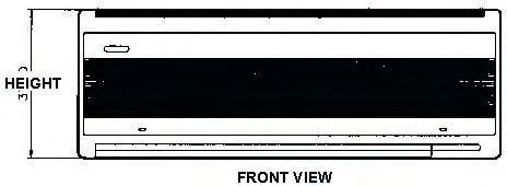
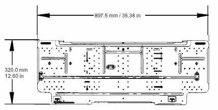
120 PRODUCT SPECIFICATIONS WMH 12
121 LOCATION & CLEARANCES Service Access 18" Min. 1" Min. Close to the wall application assures free, unobstructed air to the other two sides. In more confined application spaces, such as corners, provide a minimum 1 clearance on all air inlet sides. Allow 18 minimum for service access to the compressor compartment and controls. The top of the unit should be completely unobstructed. If units are to be located under an overhang, there should be a minimum of 36 clearance and provisions made to deflect the warm discharge air out from the overhang. LOCATION Service Access 18" Min. 1" Min. 1" If unit is to be located under an overhang, there should be a minimum of 36 clearance and provisions made to deflect the warm discharge air out from the overhang. If the outdoor unit is mounted above the air handler, the maximum lift should not exceed 7 (suction line). If air handler is mounted above condensing unit, the lift should not exceed 5 (liquid line.). Refer to Figure 3 and Table 1 for maximum refrigerant line lengths. 1" OUTDOOR UNIT PITCH SUCTION LINE TOWARD OUTDOOR UNIT 1/2" FOR EVERY 1' OF LINE INDOOR UNIT ABOVE OR LEVEL TO OUTDOOR UNIT INDOOR UNIT FIGURE 1 OUTDOOR UNIT LIQUID LINE 7' MAX. ADDITIONAL SUCTION LINE OIL TRAP FOR EACH 2 ' RISE OF PIPE 1" Min. LIQUID LINE SUCTION LINE OIL TRAPS WHEN INDOOR UNIT IS 4 FEET OR MORE BELOW OUTDOOR UNIT INDOOR UNIT INDOOR UNIT BELOW OUTDOOR UNIT 8' Service Access 18" Min. OUTDOOR UNIT INVERTED LOOP LIQUID LINE INDOOR UNIT 5' MAX. SUCTION LINE FIGURE 3 1" Min. 1". 1". FIGURE 2 Service Access 18" Min. The condensing unit must be mounted on a solid, level foundation, i.e. pre-formed concrete slab or other suitable base. For rooftop application, make sure the building construction can support the weight and that proper consideration is given to the weather-tight integrity of the roof. The condensing unit contains moving components and can vibrate; therefore, sound is also a consideration in rooftop application. Since this unit discharges warm condenser air from the top with cooler air being drawn in three sides, plantings can be made in relatively close proximity to the unit. Owners should be advised to avoid lawn mower discharge toward the unit depositing debris on the fan coil surface reducing product efficiency. 121
122 PRODUCT DESIGN This section gives a basic description of cooling unit operation, its various components and their basic operation. Ensure your system is properly sized for heat gain and loss according to methods of the Air Conditioning Contractors Association (ACCA) or equivalent. CONDENSING UNIT These units are designed for free air discharge. Condensed air is pulled through the condenser coil by a direct drive propeller fan and then discharged from the cabinet top. The unit requires no additional resistance (i.e. duct work) and should not be added. The Goodman Remote Heat Pump condensing units are designed for dual voltage single phase applications. The 3, 4, and 5 ton models are also available for 23V 3 phase applications. The 7.5 and 1 ton models are available in 23V and 46V 3 phase applications. The units range in size from 1.5 to 5-ton and have a rating of 1 through 13 SEER. SEER efficiency is dependent upon the unit and its components. Refer to the "Technical Information" manual of the unit you are servicing for further details. The Goodman Remote Condensing Units range in size from 1.5 through 5 ton and have a rating of 1 through 14 SEER. Efficiency is dependent upon the unit and its components. Refer to the Technical Information manual of the unit you are servicing for further details. Goodman Remote Condensing Units are designed for volt single phase applications. The 3, 4, 5, 7.5 and 1 ton models are also available for 23V and 46V 3 phase applications. Suction and Liquid Line Connections The suction and liquid line connections of the unit are set up for field piping with refrigerant-type copper. Front seating valves are factory-installed to accept the field-run copper. The total refrigerant charge needed for a normal operation is also factory-installed. For additional refrigerant line set information, refer to the "Technical Information" manual of the unit you are servicing. Compressors Goodman unit use a mix of reciprocating and scroll compressors. There are a number of design characteristics which differentiate the scroll compressor from the reciprocating compressor. One is the scroll. A scroll is an involute spiral which, when matched with a mating scroll form as shown, generates a series of crescent shaped gas pockets between the two members. During compression, one scroll remains stationary (fixed scroll) while the other form (orbiting scroll) is allowed to orbit (but not rotate) around the first form. As this motion occurs, the pockets between the two forms are slowly pushed to the center of the two scrolls while simultaneously being reduced in volume. When the pocket reaches the center of the scroll form, the gas, which is now at a high pressure, is discharged out of a port located at the center. During compression, several pockets are being compressed simultaneously, resulting in a very smooth process. Both the suction process (outer portion of the scroll members) and the discharge process (inner portion) are continuous. Some design characteristics of the Compliant Scroll compressor are: Compliant Scroll compressors are more tolerant of liquid refrigerant. NOTE: Even though the compressor section of a Scroll compressor is more tolerant of liquid refrigerant, continued floodback or flooded start conditions may wash oil from the bearing surfaces causing premature bearing failure. Compliant Scroll compressors use white oil which is compatible with 3GS. 3GS oil may be used if additional oil is required. Compliant scroll compressors perform "quiet" shutdowns that allow the compressor to restart immediately without the need for a time delay. This compressor will restart even if the system has not equalized. NOTE: Operating pressures and amp draws may differ from standard reciprocating compressors. This information can be found in the unit's Technical Information Manual. 122
123 PRODUCT DESIGN WARNING When installing or servicing this equipment, safety clothing, including hand and eye protection, is strongly advised. If installing this equipment in an area that has special safety requirements (hard hats etc.), observe these requirements. To protect the unit when welding close to the painted surfaces, the use of a quenching cloth is strongly advised to prevent scorching or marring of the equipment finish. WARNING HIGH VOLTAGE! Disconnect ALL power before servicing or installing this unit. Multiple power sources may be present. Failure to do so may cause property damage, personal injury or death. WARNING The unit MUST have an uninterrupted, unbroken electrical ground to minimize the possibility of personal injury if an electrical fault should occur. The electrical ground circuit may consist of an appropriately sized electrical wire connecting the ground lug in the unit control box to the building electrical service panel. Other methods of grounding are permitted if performed in accordance with the National Electric Code (NEC)/ American National Standards Institute (ANSI)/ National Fire Protection Association (NFPA) 7 and local/state codes. In Canada, electrical grounding is to be in accordance with the Canadian Electric Code CSA C22.1. Failure to observe this warning can result in electrical shock that can cause personal injury or death. WARNING If this appliance is installed in an enclosed area such as a garage or utility room with any carbon monoxide (CO) producing appliance (i.e. automobile, furnace, water-heaters, etc.), ensure the area is properly ventilated. WARNING The United States Environmental Protection Agency ( EPA ) has issued various regulations regarding the introduction and disposal of refrigerants introduced into this unit. Failure to follow these regulations may harm the environment and can lead to the imposition of substantial fines. These regulations may vary by jurisdiction. A certified technician must perform the installation and service of this product. Should questions arise, contact your local EPA office. Violation of EPA regulations may result in fines or penalties. AIR HANDLERS *See AirHandler Specification Sheet for Proper Combinations. SOME AIR HANDLERS USE DIRECT DRIVE MOTORS. POWER SUPPLY IS V, 5 HZ, 1 PHASE INSTALLATION Before installing this appliance insure that it is properly sized and adequate power is available. This appliance can be installed in the vertical or right horizontal position without modification. The horizontal left and downflow positions require product modification. This product is designed for zero centimeter ( cm) clearance; however, adequate access for service or replacement must be considered without removing permanent structure. This unit can be installed on a platform when deemed necessary. In an attic installation a secondary drain pan must be provided by the installer and placed under the entire unit with a separate drain line properly sloped and terminated in an area visible to the owner. This secondary drain pan is required in the event that there is a leak or main drain blockage. Closed cell insulation should be applied to the drain lines in unconditioned spaces where sweating may occur. Appliances installed in garages, warehouses or other areas where they may be subjected to mechanical damage must be suitably guarded against such damage by installing behind protective barriers, being elevated or located out of the normal path of vehicles. When installed on a base, the base must also be protected by similar means. Heating and cooling equipment located in garages, which may generate a glow, spark or flame capable of igniting flammable vapors, must be installed with the ignition source at least 18"[46cm] above the floor level. When more than one appliance is installed in a building it shall be permanently identified as to the area or space serviced by the equipment. When this product is installed in the vertical position in an unconditioned space, remove the horizontal drain pan and install the following insulation kit Unit A24--2RA A36--2RA A48--2RA A61--2RA Kit No. DPI18-3/2 DPI36-42/2 DPI48-61/2 This kit is used to prevent sweating on the vertical drain pan. 123
124 SYSTEM OPERATION COOLING The refrigerant used in the system is R-22. It is clear and colorless and the chemical formula is CHCLF 2. The boiling point, at atmospheric pressure is F. A few of the important principles that make the refrigeration cycle possible are: heat always flows from a warmer to a cooler body, under lower pressure a refrigerant will absorb heat and vaporize at a low temperature, the vapors may be drawn off and condensed at a higher pressure and temperature to be used again. In the cooling mode, the indoor evaporator coil functions to cool and dehumidify the air conditioned spaces through the evaporative process taking place within the coil tubes. NOTE: Actual temperatures and pressures are to be obtained from the "Cooling Performance Chart." High temperature, high pressure vapor leaves the compressor through the discharge line, through the reversing valve on heat pump models, and enters the condenser coil. Air drawn through the condenser coil by the condenser fan causes the refrigerant to condense into a liquid by removing heat from the refrigerant. As the refrigerant is cooled below its condensing temperature it becomes subcooled. The subcooled high pressure liquid refrigerant now leaves the condenser coil via the liquid line until it reaches the indoor expansion device. As the refrigerant passes through the expansion device and into the evaporator coil a pressure drop is experienced causing the refrigerant to become a low pressure vapor. Low pressure saturated refrigerant enters the evaporator coil where heat is absorbed from the warm air drawn across the coil by the evaporator blower. As the refrigerant passes through the last tubes of the evaporator coil it becomes superheated, that is, it absorbs more heat than is necessary for the refrigerant to vaporize. Maintaining proper superheat assures that liquid refrigerant is not returning to the compressor which can lead to early compressor failure. Low pressure superheated vapor leaves the evaporator coil and returns through the suction line, and on heat pump models through the reversing valve, to the compressor where the cycle begins again. COOLING CYCLE Cooling When the contacts of the room thermostat close, R to Y and G in the unit are energized. This energizes the compressor contactor, the condenser fan motor, and indoor blower motor. When the thermostat is satisfied, it opens its contacts, breaking the low voltage circuit, causing the compressor contactor to open and indoor fan to stop after the fan off delay. If the room thermostat fan selector switch should be set to the "on" position then the indoor blower would run continuous rather than cycling with the compressor. HEATING CYCLE Heat Pump Models On heat pump units, when the room thermostat is set to the heating mode, the reversing valve is not energized. This is an indication to the defrost board that the unit is in the heating mode. As long as the thermostat is set for heating, the reversing valve will be in the de-energized position for heating except during a defrost cycle. On a demand for first stage heat with heat pump units, the room thermostat energizes Y and G. This supplies 24Vac to terminal Y of the defrost board, the compressor contactor and the G terminal in the unit. The compressor starts in the heating mode and the indoor blower motor starts. When 24Vac is present at terminal Y of the defrost board during the heating mode, the board accumulates compressor run time. When the first stage heat demand Y is satisfied, the room thermostat will remove the 24Vac from Y and G. The compressor turns off and the indoor blower will stop after the fan off delay. The defrost board will store the compressor s accumulated run time in memory. When auxiliary electric heaters are used, a two stage heating single stage cooling thermostat must be installed. Should the second stage heating contacts in the room thermostat close, which would be wired to W1 at the unit low voltage connections, this would energize the coil(s) of the electric heat relay(s). Contacts within the relay(s) will close, bringing on the electric resistance heaters. If auxiliary electric heaters should be used, they may be controlled by outdoor thermostats. 124
125 SYSTEM OPERATION Emergency Heat Mode (Heat Pumps) NOTE: The following only applies if the unit has an approved electric heat kit installed for auxiliary heating. With the thermostat set to the emergency heat position and a call for 2nd stage heat, R to W1 will e energized. This will energize the electric heat sequencers. When the normally open contacts of the heat sequencers close, this will energize the electric resistance heat and also the indoor blower motor through the normally closed contacts of the EBTDR. DEFROST CYCLE The defrosting of the outdoor coil is jointly controlled by the defrost control board and the defrost thermostat. Solid State Defrost Control During operation the power to the circuit board is controlled by a temperature sensor, which is clamped to a return bend on the outdoor coil. Defrost timing periods of 3, 6, or 9 minutes may be selected by connecting the circuit board jumper to 3, 6, or 9 respectively. Accumulation of time for the timing period selected starts when the sensor closes (approximately 31 F), and when the room thermostat calls for heat. At the end of the timing period, the unit s defrost cycle will be initiated provided the sensor remains closed. When the sensor opens (approximately 75 F), the defrost cycle is terminated and the timing period is reset. If the defrost cycle is not terminated due to the sensor temperature, a ten minute override interrupts the unit s defrost period. TEST A JUMPER WIRE C Y W2 R R DFT DF2 DF1 FAN OPERATION Continuous Fan Mode (All Models) If the thermostat calls for continuous fan, the indoor blower will be energized from the normally open contacts of the EBTDR after a 7 second delay on 2 thru 4 ton units, or through the normally open contacts of the blower relay on 5 ton units. Anytime there is a call for continuous fan, the indoor blower will be energized through the normally open contacts of the EBTDR on 2 thru 4 ton units and from the "G" terminal from the thermostat on 5 ton units, regardless of a call for heat or cool. If the thermostat is not calling for heat or cool, and the fan switch on the thermostat is returned to the automatic position, the fan will stop after a 65 second delay on all air handlers with multi-speed motors. Soft Start (AER & AEPT) Upon a call for system operation, the blower motor provides a soft start, i.e. the airflow delivered to the system "ramps" from zero to the system's full air flow requirements. Ramping the airflow during the system start up matches the airflow closer to the immediate system capacity to eliminate the complaints of "warm" or "cold air blasts". Ramping the airflow from zero to full system requirements also serves to eliminate the perceived noise and distraction which occurs on start up with the typical airhandler. Upon a call to shut down system operation, the blower motor provides a soft stop, i.e. the airflow delivered to the system ramps down to approximately 5% of the full system requirements and remains there for a period of time and then ramps down to a full stop. The shut down air profile is intended to take the maximum advantage of the residual cooling or heating capacity of the indoor coil without "warm" or cold air blasts". Ramping the airflow from full system requirements to zero also eliminates the perceived noise and distraction which occurs on shut down with a typical airhandler. 125

126 SYSTEM OPERATION COOLING CYCLE In the cooling mode, the orifice is pushed into its seat, forcing refrigerant to flow through the metered hole in the center of the orifice. 126
Service Instructions. DCG Gas Electric/DCC Cooling/DCH Heat Pumps Commercial Package Units with R-410A Refrigerant 3-6 Tons & Accessories
 Service Instructions DCG Gas Electric/DCC Cooling/DCH Heat Pumps Commercial Package Units with R-410A Refrigerant 3-6 Tons & Accessories This manual is to be used by qualified, professionally trained HVAC
PRODUCT SPECIFICATIONS
 CPLT SERIES SPLIT SYSTEM HEAT PUMP SEER TO TON The CPLT features an attractive louvered metal guard to protect the coil from damage and strengthen the unit. Designed for ground-level or rooftop mount,
PRODUCT SPECIFICATIONS
 CPLJ SERIES SEER SPLIT SYSTEM HEAT PUMP COOLING CAPACITY: 6, TO 6, BTU/H HEATING CAPACITY: 6, TO 6, BTU/H ½ TO TON The CPLJ features an attractive louvered metal guard that protect the coil from damage
PRODUCT SPECIFICATIONS
 16 SEER / R-410A HIGH-EFFICIENCY 2- TO 5-TON SPLIT SYSTEM AIR CONDITIONER COOLING CAPACITY: 24,000 BTU/H TO 57,000 BTU/H The Goodman 16 SEER Air Conditioner uses the environmentally friendly refrigerant
AEPF. 1½ to 5 Tons. Contents Nomenclature... 2 Product Specifications... 3 Dimensions... 4 Wiring Diagram... 6 Accessories... 7
 Multi-Position, Variable-Speed Air Handlers 1½ to 5 Tons Standard Features Suitable for use with R-410A and R-22 refrigerants Check flowrater expansion device for cooling and heat pump applications Variable-speed
ADPF PRODUCT SPECIFICATIONS THREE-SPEED AIR HANDLER 1½ TO 5 TON DEDICATED DOWNFLOW
 ADPF THREE-SPEED AIR HANDLER The ADPF Dedicated Downfl ow Three-Speed Air Handler is suitable for use with refrigerants R-410A and R-22. The unit features a check flowrater expansion device and may be
PC SERIES 50 Hertz PRODUCT SPECIFICATIONS. Self-Contained Packaged Air Conditioners. 4 and 5 Ton [14.1 kw to 17.6 kw]
![PC SERIES 50 Hertz PRODUCT SPECIFICATIONS. Self-Contained Packaged Air Conditioners. 4 and 5 Ton [14.1 kw to 17.6 kw]](/thumbs/87/95723941.jpg "PC SERIES 50 Hertz PRODUCT SPECIFICATIONS. Self-Contained Packaged Air Conditioners. 4 and 5 Ton [14.1 kw to 17.6 kw]") PC SERIES 50 Hertz Self-Contained Packaged Air Conditioners 4 and 5 Ton [14.1 kw to 17.6 kw] Nominal Cooling Capacity: 48,000 to 60,000 BTUH The PC 50 Hz self-contained packaged air conditioners are designed
PC SERIES 50 Hertz Self-Contained Packaged Air Conditioners 4 and 5 Ton [14.1 kw to 17.6 kw] Nominal Cooling Capacity: 48,000 to 60,000 BTUH The PC 50 Hz self-contained packaged air conditioners are designed
AE/AH R410A Window Air Conditioners & Heat Pumps
 TECHNICAL MANUAL AL AE/AH R410A Window Air Conditioners & Heat Pumps All safety information must be followed. See Installation instructions for more safety precautions. Refer to the appropriate Parts Catalog
ACNF Series. Ceiling-Mount Air Handlers 1½ to 2½ Tons
 ACNF Series Ceiling-Mount Air Handlers 1½ to 2½ Tons Standard Features Suitable for use with refrigerants R-410A and R-22 Check flowrater for heat pump and cooling-only applications All-aluminun tube/aluminum
Goodman Air Handler Wiring Diagram
 GOODMAN AIR HANDLER WIRING DIAGRAM PDF - Are you looking for goodman air handler wiring diagram Books? Now, you will be happy that at this time goodman air handler wiring diagram PDF is available at our
Commercial High-Efficiency Condensing Units
 FORM NO. A22-194 REV. 2 Supersedes Form No. A22-194 Rev. 1 Commercial High-Efficiency Condensing Units RAWL High Efficiency 6.5 & 7.5 TON MODEL [22.86 & 26.38 kw] TABLE OF CONTENTS Model Number Designation...2
UP TO 17.5 SEER / 13.5 EER / 9.5 HSPF HEAT PUMP ENVIRONMENTALLY BALANCED R- 410A REFRIGERANT 2 THRU 5 TONS SPLIT SYSTEM
 EFFICIENT UP TO 17.5 SEER / 13.5 EER / 9.5 HSPF HEAT PUMP ENVIRONMENTALLY BALANCED R- 410A REFRIGERANT 2 THRU 5 TONS SPLIT SYSTEM 208/230 Volt 1- phase REFRIGERATION CIRCUIT S 2- stage scroll compressors
N4H4. Product Specifications 14 SEER HEAT PUMP. ENVIRONMENTALLY SOUND R 410A REFRIGERANT 1½ THRU 5 TONS SPLIT SYSTEM 208 / 230 Volt, 1 phase, 60 Hz
 ENVIRONMENTALLY SOUND REFRIGERANT N4H4 Performance Series Product Specifications 14 SEER HEAT PUMP ENVIRONMENTALLY SOUND R 410A REFRIGERANT 1½ THRU 5 TONS SPLIT SYSTEM 208 / 230 Volt, 1 phase, 60 Hz REFRIGERATION
TECHNICAL MANUAL. ARPT**14**, ARUF**14**, ASPT**14**, ASUF**14** Air Handlers
 TECHNICAL MANUAL AL ARPT**4**, ARUF**4**, ASPT**4**, ASUF**4** Air Handlers Refer to Service Manual RS600006 for installation, operation & troubleshooting information. All safety information must be followed
Technical Development Program. COMMERCIAL HVAC PACKAGED EQUIPMENT Split Systems PRESENTED BY: Ray Chow Sigler
 Technical Development Program COMMERCIAL HVAC PACKAGED EQUIPMENT Split Systems PRESENTED BY: Ray Chow Sigler Menu Section 1 Section 2 Section 3 Section 4 Section 5 Section 6 Section 7 Introduction System
R4H4. Product Specifications
 R4H4 Product Specifications EFFICIENT 14 SEER HEAT PUMP ENVIRONMENTALLY BALANCED REFRIGERANT 1-1/2 THRU 5 TONS SPLIT SYSTEM 208 / 230 Volt, 1- phase, 60 Hz REFRIGERATION CIRCUIT S Scroll compressors on
INSTALLATION & OPERATING INSTRUCTIONS FOR CEILING MOUNT AIR HANDLERS AC SERIES
 C US INSTALLATION & OPERATING INSTRUCTIONS FOR CEILING MOUNT AIR HANDLERS AC SERIES Made in the USA by: Goodman Manufacturing Company, L.P. I0-240B 2550 North Loop West, Suite 400, Houston, TX 77092 www.goodmanmfg.com
R4H4. Product Specifications
 ENVIRONMENTALLY SOUND REFRIGERANT R4H4 Product Specifications EFFICIENT 14 SEER HEAT PUMP ENVIRONMENTALLY SOUND R 410A REFRIGERANT 1 1/2 THRU 5 TONS SPLIT SYSTEM 208 / 230 Volt, 1 phase, 60 Hz REFRIGERATION
TECHNICAL GUIDE LISTED. SPLIT-SYSTEM AIR CONDITIONERS 10 SEER R22 60Hz MODELS: AC036X10(3,4) THRU 060 (3 THRU 5 NOMINAL TONS, 3 PH) DESCRIPTION
 THRU 060 (3 THRU 5 NOMINAL TONS, 3 PH) DESCRIPTION") TECHNICAL GUIDE SPLIT-SYSTEM AIR CONDITIONERS 10 SEER R22 60Hz MODELS: AC036X10(3,4) THRU 060 (3 THRU 5 NOMINAL TONS, 3 PH) LISTED ISO 9001 Certified Quality Management System Due to continuous product
TECHNICAL GUIDE SPLIT-SYSTEM AIR CONDITIONERS 10 SEER R22 60Hz MODELS: AC036X10(3,4) THRU 060 (3 THRU 5 NOMINAL TONS, 3 PH) LISTED ISO 9001 Certified Quality Management System Due to continuous product
PAJ3. Product Specifications
 13 SEER, R 410A PACKAGE AIR CONDITIONER FOR MANUFACTURED HOUSING, RESIDENTIAL, AND LIGHT COMMERCIAL APPLICATIONS 2 5 TONS Single Phase, 208/230 V, 60 Hz BUILT TO LAST, EASY TO INSTALL AND SERVICE Compact,
1-1/2 THRU 2-1/2 TONS SPLIT SYSTEM FWM Series
 1-1/2 THRU 2-1/2 TONS SPLIT SYSTEM FWM Series Rated in accordance with ARI Standard 210. Certification applies only when used with proper components as listed with ARI. FEATURES Designed as an upflow indoor
Product Data. 50LJS/TJS Single- Package. Features / Benefits. Rooftop Units - 50 Hz 6 to 12 Nominal Tons
 007-014 Single- Package Rooftop Units - 50 Hz 6 to 12 Nominal Tons Product Data Single package rooftop cooling units with electric heat option. Compact, horizontal discharge units (vertical discharge option),
SPLIT SYSTEM COOLING 1½ 5 TON ALLEGIANCE 14 MODELS 4A7A C/30-060B American Standard Heating & Air Conditioning
 SPLIT SYSTEM COOLING 1½ 5 TON ALLEGIANCE 14 MODELS 4A7A4018-24C/30-060B 2009 American Standard Heating & Air Conditioning PUB.. 12-1173-04 April 2009 Features and Benefits Duration compressor Efficiency
PACKAGE AIR CONDITIONER
 PACKAGE AIR CONDITIONER FORM NO. ATZ-206 TZAA- HIGH EFFICIENCY SERIES NOMINAL SIZE 10 TON [35.2 kw] 10 TON MODEL [35.2 kw] This product is shipped with a nitrogen holding charge that must be vented prior
TECHNICAL GUIDE LISTED. SPLIT-SYSTEM AIR CONDITIONERS 10 SEER R22 60Hz MODELS: H*BA-(T,W)036 THRU 076 (3 THRU 6.3 NOMINAL TONS, 3 PH) DESCRIPTION
036 THRU 076 (3 THRU 6.3 NOMINAL TONS, 3 PH) DESCRIPTION") TECHNICAL GUIDE SPLIT-SYSTEM AIR CONDITIONERS 10 SEER R22 60Hz MODELS: H*BA-(T,W)036 THRU 076 (3 THRU 6.3 NOMINAL TONS, 3 PH) LISTED MODELS: 018-060 (3 PH) MODELS: 076 (3 PH) ISO 9001 Certified Quality
TECHNICAL GUIDE SPLIT-SYSTEM AIR CONDITIONERS 10 SEER R22 60Hz MODELS: H*BA-(T,W)036 THRU 076 (3 THRU 6.3 NOMINAL TONS, 3 PH) LISTED MODELS: 018-060 (3 PH) MODELS: 076 (3 PH) ISO 9001 Certified Quality
SPLIT SYSTEM HEAT PUMP 1½ 5 TON HERITAGE 13 MODELS 2A6H A American Standard Heating & Air Conditioning
 SPLIT SYSTEM HEAT PUMP 1½ 5 TON HERITAGE 13 MODELS 2A6H3018-060A 2008 American Standard Heating & Air Conditioning PUB. NO. 12-1216-02 June 2008 Features and Benefits Duration compressor Efficiency up
K*ES120 DESCRIPTION TECHNICAL GUIDE SPLIT-SYSTEM EVAPORATOR BLOWERS 10 NOMINAL TONS EER 8.5 ACCESSORIES FIELD INSTALLED TABLE 1: ARI RATINGS*
 TECHNICAL GUIDE SPLIT-SYSTEM EVAPORATOR BLOWERS K*ES120 10 NOMINAL TONS EER 8.5 DESCRIPTION These completely assembled dual circuit evaporator blower units include a well-insulated cabinet, a DX cooling
Split System Heat Pump Product Data
 Split System Heat Pump Product Data XR 13 4TWR3018-060 1½ 5 Tons PUB. NO. 22-1795-06 Features and Benefits Climatuff compressor All aluminum Spine Fin coil Quick-Sess cabinet, service access and refrigerant
NH4H4. Product Specifications 14 SEER HORIZONTAL DISCHARGE HEAT PUMP FOR USE WITH DUCTED INDOOR UNIT
 ENVIRONMENTALLY SOUND REFRIGERANT NH4H4 Product Specifications 14 SEER HORIZONTAL DISCHARGE HEAT PUMP FOR USE WITH DUCTED INDOOR UNIT ENVIRONMENTALLY SOUND R 410A REFRIGERANT 1 1/2 THRU 5 TONS, 208/230
ASPT Series. Multi-Position, Multi-Speed, ECM-Based Air Handler with Internal TXV 1½ to 5 Tons. Contents. Product Features
 Series Multi-Position, Multi-Speed, ECM-Based Air Handler with Internal TXV ½ to Tons Contents Air Handler Nomenclature... Heater Kit Nomenclature... Product Specifications... Dimensions... Airflow Data...
WCH5**4. Product Specifications
 HEAT PUMP HIGH EFFICIENCY 15 SEER 1-1/2 THRU 5 TONS SPLIT SYSTEM ENVIRONMENTALLY BALANCED R- 410A REFRIGERANT 208 / 230 Volt, 1- phase, 60 Hz This product has been designed and manufactured to meet ENERGY
ASPT Series. Multi-Position, Multi-Speed, ECM-Based Air Handler with Internal TXV 1½ to 5 Tons. Contents. Product Features
 Series Multi-Position, Multi-Speed, ECM-Based Air Handler with Internal TXV ½ to Tons Contents Air Handler Nomenclature... Heater Kit Nomenclature... Product Specifications... Dimensions... Airflow Data...
N4H4. Product Specifications
 14 SEER HEAT PUMP ENVIRONMENTALLY BALANCED R- 410A REFRIGERANT 1½ THRU 5 TONS SPLIT SYSTEM 208/230 Volt 1- phase, 208/230 Volt 3- phase, 460 Volt 3- phase; 60 Hz REFRIGERATION CIRCUIT S Scroll compressors
RTG Ultron. Up to 16 SEER. Specification Sheet. Split System Heat Pump
 RTG Ultron Split System Heat Pump Specification Sheet Up to 16 SEER Cooling : 35,000-56,500 BTUH Heating : 33,600-56,400 BTUH LIMITED WARRANTY Lifetime Replacement of Entire Unit if Compresssor Fails 10-Year
VERTICAL MOUNT AIR HANDLERS
 VERTICAL MOUNT AIR HANDLERS INSTALLATION INSTRUCTIONS 2005-2009 Goodman Manufacturing Company, L.P. 5151 San Felipe, Suite 500, Houston, TX 77056 www.goodmanmfg.com -or- www.amana-hac.com P/N: IO-281J
UP to 14.5 SEER, PACKAGE AIR CONDITIONER UNIT, 2 to 5 TONS 208/230 Volt, 1 phase, 60 Hz REFRIGERATION CIRCUIT
 SOUND REFRIGERANT ENVIRONMENTALLY PAJ4 Product Specifications UP to 14.5 SEER, PACKAGE AIR CONDITIONER UNIT, 2 to 5 TONS 208/230 Volt, 1 phase, 60 Hz REFRIGERATION CIRCUIT Environmentally sound R-410A
Commercial High-Efficiency Condensing Units
 FORM NO. A22-193 REV. 3 Supersedes Form No. A22-193 Rev. 2 Commercial High-Efficiency Condensing Units 15 & 20 TON MODEL [52.8 & 70.3 kw] 10 & 12.5 TON MODEL [35.2 & 44.0 kw] 10 THROUGH 20 NOMINAL TON
Split System Cooling Product & Performance Data
 Split System Cooling Product & Performance Data Three Phase 2TTA3048-060A3 4 5 Tons PUB. NO. 22-1770-03 Features and Benefits All aluminum Spine Fin coil Durable base, fast complete drain, weather proof
Split System Heat Pump Product Data
 Split System Heat Pump Product XL 15i 4TWX5018 42A, 049E, 061E 1½ 5 Tons PUB. NO. 22-1800-07 Features and Benefits Climatuff compressor Efficiency up to 16.00 SEER and 9.0 HSPF All aluminum Spine Fin coil
ARPT Series. Multi-Position. 2 to 5 Tons. Internal TXV, Multi-Speed PSC Motor
 Contents Air Handler Nomenclature... Heater Kit Nomenclature...... Dimensions...4 Airflow Data...5 Heat Kit Data...6 Wiring Diagram... Accessories... Product Features Internal factory-installed thermal
N4A6. Product Specifications
 ENVIRONMENTALLY SOUND REFRIGERANT N4A6 Product Specifications EFFICIENT UP TO 16.5 SEER/12.2 13.0 EER AIR CONDITIONER ENVIRONMENTALLY SOUND R 410A REFRIGERANT 1 1/2 THRU 5 TONS SPLIT SYSTEM 208/230 Volt,
AEPT SERIES PRODUCT SPECIFICATIONS. Multi-Position Air Handler. 2 to 5 Ton
 AEPT SERIES Multi-Position Air Handler 2 to 5 Ton The AEPT multi-position air handler is approved for modular homes and may be installed in a utility room, closet, aclove, basement or attic. Standard Features
ASUF Series. Multi-Position. Air Handler 1½ to 5 Tons
 ASUF Series Multi-Position Multi-Speed ECM Based Product Features Check flowrator for cooling and heat pump applications Direct drive, multi-speed ECM blower motor All-aluminum evaporator coil Coil mounting
WJH4 Product Specifications
 UP TO 14.5 SEER, R 410A PACKAGE HEAT PUMP FOR MANUFACTURED HOUSING, RESIDENTIAL, AND LIGHT COMMERCIAL APPLICATIONS 2 5 TONS Single Phase, 208/230 V, 60 Hz Use of the AHRI Certified TM Mark indicates a
AVPTC Multi-Position, Internal Txv
 Multi-Position, Internal Txv Variable-Speed ECM Based Comfortnet Compatible Air Handler 1½ to 5 Tons Contents Air Handler Nomenclature... Heater Kit Nomenclature......3 Dimensions...4 Airflow Data...5
Split System Heat Pump Product Data
 Split System Heat Pump Product XL 15i 4TWX5 1½ 5 Tons PUB. NO. 22-1800-15 Features and Benefits Climatuff compressor Efficiency up to 16.25 SEER and 9.7 HSPF All aluminum Spine Fin coil WeatherGuard II
WMHP Series R410a Heat Pump INSTALLATION INSTRUCTIONS
 WMHP Series R410a Heat Pump INSTALLATION INSTRUCTIONS **WARNING TO INSTALLER, SERVICE PERSONNEL AND OWNER** Altering the product or replacing parts with non authorized factory parts voids all warranty
Split System Cooling Product Data
 Split System Cooling Product Data Three Phase 4TTA3 3 5 Tons PUB. NO. 22-1791-16-EN Features and Benefits All aluminum Spine Fin coil WeatherGuard fasteners Quick-Sess cabinet, service access and refrigerant
Split System Cooling Product Data
 Split System Cooling Product Data XR 13 4TTR3018-060 1½ 5 Tons PUB. NO. 22-1842-05 Features and Benefits Climatuff compressor Efficiency up to 14.00 SEER All aluminum Spine Fin coil WeatherGuard fasteners
AVPTC Multi-Position, Internal Txv
 Multi-Position, Internal Txv Variable-Speed ECM Based Comfortnet Compatible Air Handler 1½ to 5 Tons Contents Air Handler Nomenclature... Heater Kit Nomenclature...... Dimensions...4 Airflow Data...5 Heat
ASUF Series. Multi-Position. Air Handler 1½ to 5 Tons
 Product Features Check flowrator for cooling and heat pump applications Direct drive, multi-speed ECM blower motor All-aluminum evaporator coil Coil mounting track for quick repositioning Optimized for
Split System Cooling Product Data
 Split System Cooling Product Data Three Phase 4TTA3 2½ 5 Tons PUB. NO. 22-1791-14-EN Features and Benefits All aluminum Spine Fin coil WeatherGuard fasteners Quick-Sess cabinet, service access and refrigerant
TECHNICAL MANUAL. PBC/PBE/PBH Through-The-Wall R-410A Air Conditioners & Heat Pumps
 TECHNICAL MANUAL AL PBC/PBE/PBH Through-The-Wall R-410A Air Conditioners & Heat Pumps All safety information must be followed See Installation instructions for more safety precautions. Refer to the appropriate
FLD = Furnished by Trane U.S. Inc. / Installed by Equipment Submittal Page 3 of 13
 Tag Data - Split System Air Conditioning Units (Large) (Qty: 6) Item Tag(s) Qty Description Model Number A1 20 ton vfd 6 6-25 Ton Unitary Split Systems ( SSC2 TTA24004H00-TWE240E404A TTA Air Condensing
TECHNICAL GUIDE DESCRIPTION SPLIT-SYSTEM AIR-COOLED CONDENSING UNITS. HA300, HB360, HB480 & HB thru 50 NOMINAL TONS (50 Hz)
") DESCRIPTION These units are completely assembled, piped and wired at the factory to provide one-piece shipment and rigging. Each unit is pressurized with a holding charge of refrigerant-22 for storage
DESCRIPTION These units are completely assembled, piped and wired at the factory to provide one-piece shipment and rigging. Each unit is pressurized with a holding charge of refrigerant-22 for storage
FF1DNA, FF1DNE FAN COIL UNITS. Sizes 018, 024, 030. Form No. PDS FF1D.18.3 FEATURES FF1D
 FAN COIL UNITS FF1DNA, FF1DNE Sizes 018, 024, 030 FF1D FEATURES The FF1DNA and FF1DNE Fan Coil units are designed as upflow indoor air handlers for split-system heat pumps and air conditioners. They are
AVPTC. Multi-Position, Variable-Speed ECM Based Air Handler with Internal TXV ComfortNet Compatible 1½ to 5 Tons. Contents.
 Multi-Position, Variable-Speed ECM Based Air Handler with Internal TXV ComfortNet Compatible 1½ to 5 Tons Contents Air Handler Nomenclature... Heater Kit Nomenclature... Product Specifications... 3 Dimensions...
PAR5. Product Specifications
 TM PAR5 Product Specifications UP to 16 SEER, UP to 12.5 EER, PACKAGE AIR CONDITIONING UNITS, 2 5 TONS 208/230 Volt, 1 phase, 60 Hz 208/230 Volt, 3 phase, 60 Hz REFRIGERATION CIRCUIT Environmentally balanced
MBR. Multi-Position, Multi-Speed Modular Blower With PSC Motor 1½ to 5 TONS. Contents. Product Features
 M Multi-Position, Multi-Speed Modular Blower With PSC Motor 1½ to 5 TONS Contents Air Handler Nomenclature... Heater Kit Nomenclature... Product Specifications... Dimensions... 4 Airflow Data... 5 Heat
ARPT Series. Multi-Position, Multi-speed Air Handler with Internal TXV and PSC Motor 2 to 5 Tons. Contents. Product Features
 Series Multi-Position, Multi-speed Air Handler with Internal TXV and PSC Motor to 5 Tons Contents Air Handler Nomenclature... Heater Kit Nomenclature... Product Specifications... Dimensions... 4 Airflow
BCE4 PRODUCT SPECIFICATIONS ENHANCED AIR HANDLER WITH VARIABLE SPEED APPLICATION INSTALLATION CABINET COMPONENTS CONTROLS WARRANTY
 PRODUCT SPECIFICATIONS ENHANCED AIR HANDLER WITH VARIABLE SPEED FORM NO. -100 (11/2015) APPLICATION 2-5 ton sizes Upflow, horizontal, and downflow capable Sequenced for demand management External access
Supersedes: N2Y (498) N2Y (799) MODELS B1HH018 THRU THRU 5 TON (12 SEER)
 N2Y (799) MODELS B1HH018 THRU THRU 5 TON (12 SEER)") CHAMPION SERIES SINGLE PACKAGE HEAT PUMPS INSTALLATION INSTRUCTION Supersedes: 511.18-N2Y (8) 511.18-N2Y (7) MODELS B1HH018 THRU 00 1.5 THRU 5 TON (12 SEER) 035-1707-000 GENERAL YORK Model B1HH units are
CHAMPION SERIES SINGLE PACKAGE HEAT PUMPS INSTALLATION INSTRUCTION Supersedes: 511.18-N2Y (8) 511.18-N2Y (7) MODELS B1HH018 THRU 00 1.5 THRU 5 TON (12 SEER) 035-1707-000 GENERAL YORK Model B1HH units are
TECHNICAL GUIDE. Description SPLIT-SYSTEM AIR-COOLED CONDENSING UNITS YD360, 480 & THRU 50 NOMINAL TONS YTG-B-0811
 Description These units are completely assembled, piped and wired at the factory to provide one-piece shipment and rigging. Each unit is pressurized with a holding charge of Refrigerant R-410A for storage
Duct Free Systems Product Data Digest ¾ to 5 Nominal Tons
 Duct Free Systems Product Data Digest ¾ to 5 Nominal Tons Console Console Condenser & Mulit-Zone Satellite HDC, HDL, HDS & QR Condensers High Wall AN/BK Condensers Under Ceiling Cassette Copyright 2001
R 410A Ducted Horizontal Air Conditioner
 ENVIRONMENTALLY SOUND REFRIGERANT HC4A3 Product Specifications R 410A Ducted Horizontal Air Conditioner ENVIRONMENTALLY SOUND R 410A REFRIGERANT 1½ THRU 5 TONS, 208/230 Volt, 1 Phase 3 THRU 5 TONS, 208/230
AVPTC. Air Handlers 1½ to 5 Tons
 Multi-Position, Variable-Speed Air Handlers ½ to Tons Standard Features Compatible with the ComfortNet Communicating System family of products R-0A refrigerant-compatible Factory-installed thermal expansion
AR SERIES COMMERCIAL AIR HANDLERS INSTALLATION & OPERATING INSTRUCTIONS
 AR SERIES COMMERCIAL AIR HANDLERS INSTALLATION & OPERATING INSTRUCTIONS NOTE: AR models are suitable for Upflow and Horizontal Installations only. Do not use for Downflow Installations RECOGNIZE THIS SYMBOL
TECHNICAL GUIDE DESCRIPTION SPLIT-SYSTEM AIR-COOLED CONDENSING UNITS MODELS: HF-07 FEATURES B-0703
 TECHNICAL GUIDE SPLIT-SYSTEM AIR-COOLED CONDENSING UNITS MODELS: HF-07 DESCRIPTION These Sunline 2000 units are completely assembled, piped and wired at the factory to provide one-piece shipment and rigging.
AVPTC. Air Handler 1½ to 5 Tons
 Multi-Position, Variable-Speed Air Handler ½ to 5 Tons Standard Features Compatible with the ComfortNet Communicating System family of products Maximum four low-voltage wires required for operation in
TECHNICAL MANUAL. GMS8 33-3/8" 80% Gas Furnace Units 80% AFUE, Single Stage, Multi-Speed, Upflow Horizontal
 TECHNICAL MANUAL AL GMS8 33-3/8" 80% Gas Furnace Units 80% AFUE, Single Stage, Multi-Speed, Upflow Horizontal Refer to Service Manual RS6612006for troubleshooting information. All safety information must
JOB NAME: LOCATION: PURCHASER: ENGINEER: SUBMITTED TO: FOR: REFERENCE [ ] APPROVAL [ ] CONSTRUCTION [ ] SUBMITTED BY: DATE:
![JOB NAME: LOCATION: PURCHASER: ENGINEER: SUBMITTED TO: FOR: REFERENCE [ ] APPROVAL [ ] CONSTRUCTION [ ] SUBMITTED BY: DATE:](/thumbs/95/125855728.jpg "JOB NAME: LOCATION: PURCHASER: ENGINEER: SUBMITTED TO: FOR: REFERENCE [ ] APPROVAL [ ] CONSTRUCTION [ ] SUBMITTED BY: DATE:") T2HA, T3HA, and T4HA with CAHB Systems Limited Range Multi-Zone Heat Pumps Rev. 1.1 [07/07] JOB NAME: LOCATION: PURCHASER: ENGINEER: SUBMITTED TO: FOR: ERENCE [ ] APPROVAL [ ] CONSTRUCTION [ ] SUBMITTED
T2HA, T3HA, and T4HA with CAHB Systems Limited Range Multi-Zone Heat Pumps Rev. 1.1 [07/07] JOB NAME: LOCATION: PURCHASER: ENGINEER: SUBMITTED TO: FOR: ERENCE [ ] APPROVAL [ ] CONSTRUCTION [ ] SUBMITTED
PAD3. Product Specifications. 13 SEER PACKAGE AIR CONDITIONER, 2 to 5 TONS Single Phase, 208/230 V, 60 Hz REFRIGERATION CIRCUIT
 SOUND REFRIGERANT ENVIRONMENTALLY PAD3 Product Specifications 13 SEER PACKAGE AIR CONDITIONER, 2 to 5 TONS Single Phase, 208/230 V, 60 Hz REFRIGERATION CIRCUIT Environmentally sound R 410A refrigerant
PRODUCT SPECIFICATIONS 2YCC3048A1120A /1/ /
 YCC3048-SPEC-1B TAG: SPECIFICATIONS SINGLE PACKAGED GAS HEATING ELECTRIC COOLING PRODUCT SPECIFICATIONS 2/4YCC3048A107/96/120A MODEL RATED Volts/PH/Hz Performance Cooling BTUH Indoor Airflow (CFM) Power
R100 Oil-Less Refrigerant Recovery Unit
 R100 Oil-Less Refrigerant Recovery Unit Operation Manual 1 INTRODUCTION Welcome to simple, efficient refrigerant recovery with your new YELLOW JACKET Refrigerant Recovery Unit, R100. This unit combines
Split System Cooling Product Data
 Split System Cooling Product Data XR 13 4TTR3018-060 1½ 5 Tons PUB. NO. 22-1842-07 Features and Benefits Climatuff compressor Efficiency up to 14.00 SEER All aluminum Spine Fin coil WeatherGuard fasteners
SPLIT SYSTEM COOLING 1 1 / 2 5 TON MODELS 4A7A
 SPLIT SYSTEM COOLING 1 1 / 2 5 TON MODELS 4A7A6018-61 PUB. NO. 12-1350-03 February 2015 Features and Benefits DURATION compressor Efficiency up to 17.0 SEER All aluminum SPINE FIN coil WEATHERGUARD fasteners
CAS. Product Specifications. COMMERCIAL SPLIT SYSTEMS CONDENSING UNITS R 410A, 6 to 12.5 TONS BUILT TO LAST, EASY TO INSTALL AND SERVICE
 COMMERCIAL SPLIT SYSTEMS CONDENSING UNITS R 410A, 6 to 12.5 TONS BUILT TO LAST, EASY TO INSTALL AND SERVICE CAS Product Specifications Single stage cooling capacity control on all models with Micro channel
PGF SERIES 7-1/2 Ton. Belt Drive CONVERTIBLE SINGLE PACKAGE GAS/ELECTRIC UNIT
 PGF SERIES 7-1/2 Ton C Belt Drive CONVERTIBLE SINGLE PACKAGE GAS/ELECTRIC UNIT SINGLE PACKAGE Combination gas heating and electric cooling, self contained for year-round comfort. Systems can be installed
JS5BD-K(A,B) Series High Efficiency Air Conditioner 13+ SEER Residential System Ton Capacity
 Series High Efficiency Air Conditioner 13+ SEER Residential System Ton Capacity") TECHNICAL SPECIFICATIONS JS5BD-K(A,B) Series High Efficiency Air Conditioner 13+ SEER Residential System 1.5-5 Ton Capacity The JS5BD Series of air conditioners offers exceptional performance. The unit,
TECHNICAL SPECIFICATIONS JS5BD-K(A,B) Series High Efficiency Air Conditioner 13+ SEER Residential System 1.5-5 Ton Capacity The JS5BD Series of air conditioners offers exceptional performance. The unit,
SPLIT-SYSTEM HEAT PUMPS 50 AND 60 HZ DESCRIPTION
 SPLIT-SYSTEM HEAT PUMPS 50 AND 60 HZ E3FB090/E1FB120/F3EH090 & 120 7-1/2 & 10 NOMINAL TONS (60 HZ) 7 & 9 NOMINAL TONS (50 HZ) (9.0-9.2 EER) 208/230/460 VOLT ONLY 208/230 VOLT ONLY DESCRIPTION YORK has
TECHNICAL GUIDE HIGH EFFICIENCY, STANDARD ECM VERTICAL WALL MOUNT AIR HANDLERS FOR USE WITH SPLIT-SYSTEM COOLING & HEAT PUMPS MODELS: EWX*18-36
 TECHNICAL GUIDE HIGH EFFICIENCY, STANDARD ECM VERTICAL WALL MOUNT AIR HANDLERS FOR USE WITH SPLIT-SYSTEM COOLING & HEAT PUMPS MODELS: EWX*18-36 Due to continuous product improvement, specifications are
Split System Heat Pump Product Data
 Split System Heat Pump Product XR15 4TWR5 1 1 /2-5 Tons PUB. NO. 22-1832-10 Features and Benefits CLIMATUFF compressor Efficiency up to 17.0 SEER and 9.0 HSPF All aluminum SPINE FIN coil WEATHERGUARD fasteners
Split System Heat Pump Product Data
 Split System Heat Pump Product XR15 4TWR5 1 1 /2-5 Tons PUB. NO. 22-1832-13 Features and Benefits CLIMATUFF compressor Efficiency up to 17.0 SEER and 9.0 HSPF All aluminum SPINE FIN coil WEATHERGUARD fasteners
TECHNICAL GUIDE DESCRIPTION EA090/FA090 SPLIT-SYSTEM HEAT PUMPS OUTDOOR UNIT INDOOR UNIT
 TECHNICAL GUIDE SPLIT-SYSTEM HEAT PUMPS EA090/FA090 DESCRIPTION YORK has combined the latest concepts in modern technology with time-proven quality standards to design a split-system heat pump to meet
Split System Cooling Product Data
 Split System Cooling Product Data XB16 4TTB6 1 1 / 2-5 Tons PUB. NO. 22-1888-01 Features and Benefits Efficiency up to 16.0 SEER All aluminum SPINE FIN coil WEATHERGUARD fasteners QUICK-SESS cabinet, service
Product Data. 50HS Single-Package Heat Pumps to 5 Nominal Tons
 Product Data 50HS Single-Package Heat Pumps 1 1 2 to 5 Nominal Tons Single-Package Heat Pump for Manufactured Housing/Residential and Light Commercial use. Features/Benefits One-piece heat pumps with optional
13 SEER CONDENSING UNITS
 FORM NO. A11-182 REV. 8 Supersedes Form No. A11-182 Rev. 7 13 SEER CONDENSING UNITS Features Painted louvered steel cabinet. Easily accessible control box. Condenser coils constructed with copper tubing
INSTALLATION INSTRUCTIONS
 INSTALLATION INSTRUCTIONS FOR COMBINATION HEATING AND COOLING ROOFTOP UNITS RKKB SERIES 7.5, 8.5, 10, 12.5 & 15 TON [26.4, 29.9, 35.2 44 & 52.8 kw] RKMB SERIES 7.5, 8.5, 10 & 12.5 TON [26.4, 29.9, 35.2
AMERICAN STANDARD 14 MODELS 4A7B E
 SPLIT SYSTEM COOLING 1 1 / 2 5 ton AMERICAN STANDARD 14 MODELS 4A7B4018-60E PUB. NO. 12-1290-02 June 2009 Features and Benefits DURaTION compressor Efficiency up to 16.0 SEER All aluminum Spine Fin coil
Series PIN. New Construction or Renovation. Application Flexible Quiet Comfort Damage Protection
 Series PIN New Construction or Renovation Application Flexible Quiet Comfort Damage Protection ADIRONDACK AIRE New Construction or Renovation The Adirondack-Aire PIN Series zerozone chassis provides environment
PL Series Premier Indoor Plenum Coils
 IM-PLC-0667392-04 April 2016 PL Series Premier Indoor Plenum Coils Installation Instructions GENERAL ADP evaporator coils are designed for use with condensing units or heat pump units. These instructions
TECHNICAL SPECIFICATIONS
 TECHNICAL SPECIFICATIONS Model DS4BD Series M120 Product Line High Efficiency R-410A Air Conditioner 13+ SEER 1.5-5 Ton Capacity 12 YEAR ALL PARTS WARRANTY This product offers a 1 Year Dependability Promise
MBR. Multi-Position, Multi-Speed Modular Blower With PSC Motor. Contents. Product Features
 M Multi-Position, Multi-Speed Modular Blower With PSC Motor Contents Air Handler Nomenclature... Heater Kit Nomenclature... Product Specifications... Dimensions... 4 Airflow Data... 5 Heat Kit Data...
Product Data. 50ZHB 13 SEER Single--Packaged Heat Pump System with Puronr (R-- 410A) Refrigerant Single Phase 2 to 5 Nominal Tons ( )
 Refrigerant Single Phase 2 to 5 Nominal Tons ( )") 13 SEER Single--Packaged Heat Pump tem with Puronr (R-- 410A) Refrigerant Single Phase 2 to 5 Nominal Tons (024--060) Product Data Fig. 1 - Unit Single -Packaged Heat Pump Units with: S easy installation
13 SEER Single--Packaged Heat Pump tem with Puronr (R-- 410A) Refrigerant Single Phase 2 to 5 Nominal Tons (024--060) Product Data Fig. 1 - Unit Single -Packaged Heat Pump Units with: S easy installation
 RHEEM Split Systems Condensers All submitted condensers meet the 15 SEER minimum All submitted condensers meet the 208/230V specification All submitted condensers contain enhanced mufflers to help dissipate
R-410A AFFINITY SERIES DEX DEY Ton
 R-410A AFFINITY SERIES 024-048 DEY060 2-5 Ton ISO 9001 Certified Quality Management System General.......................................... 1 Installation........................................ 3 Limitations......................................
AVPTC Multi-Position, Internal Txv
 Product Features Internal factory-installed thermal expansion valves for cooling and heat pump applications Variable-speed ECM blower motor ComfortNet Communicating System compatible Auto configuration
Bosch BVA Series Air Handler
 Bosch BVA Series Air Handler 2-3-4-5 Ton Capacity R410A Product Specifications 2 Bosch IDS BVA Product Specifications Data subject to change 12.2016 Bosch Thermotechnology Corp. Product Specifications
EMBASSY SERIES SINGLE PACKAGE AIR CONDITIONERS (WATER-COOLED) C2ED060, 090, 120 & 180 5, 7-1/2, 10 & 15 Nominal Tons
 C2ED060, 090, 120 & 180 5, 7-1/2, 10 & 15 Nominal Tons") 560.20-TG1Y (388) EMBASSY SERIES SINGLE PACKAGE AIR CONDITIONERS (WATER-COOLED) C2ED060, 090, 120 & 180 5, 7-1/2, 10 & 15 Nominal Tons Each circuit includes a fully hermetic compressor with a crankcase
560.20-TG1Y (388) EMBASSY SERIES SINGLE PACKAGE AIR CONDITIONERS (WATER-COOLED) C2ED060, 090, 120 & 180 5, 7-1/2, 10 & 15 Nominal Tons Each circuit includes a fully hermetic compressor with a crankcase
MHH. 13 SEER High Efficiency R410a. SPECIFICATION sheet
 Air Conditioning and Heating SPECIFICATION sheet MHH 13 SEER High Efficiency R410a Split System Heat Pump Standard features: R410a system High efficiency compressor Compact design for easy installation