BUNN TECHNICAL TRAINING
|
|
|
- Myles Marsh
- 6 years ago
- Views:
Transcription


1 BUNN TECHNICAL TRAINING AXIOM
2 Index Unit 1: Installation Site Requirements...4 Location of the Serial Number...4 Install Preparation...4 Water Supply Install...4 Electrical Install...5 Initial Start-Up...5 Unit 2: Setup User Interface (Programming)...7 Programming Lockout...7 Programming Menus...8 Level 1 Programming (BrewWIZARD )...8 Level 2 Programming...8 Level 3 Programming...10 Machine Setup...10 Brew Oz...10 Calibrating Flow Rate...11 Enable BrewLOGIC Calibrate Temperature Probe...12 Setting Lime Adjustment...12 Resetting Refill Threshold...13 Unit 3: Machine Composition Exterior Overview...15 Product Outlets and Removable Parts...15 User Interface (Operating)...15 Accessing the Inside of the Brewer...16 Machine Function and Operations...16 Main Control Board...16 Filling System...16 Heating System...17 Dispensing System...18 Unit 4: Preventive Maintenance Preventive Maintenance...20 PM Steps...20 Unit 5: Troubleshooting Service Tools...23 Test Outputs...23 Test Switches...24 Service Fault Messages...24 Troubleshooting Components...25 Troublehsooting Refill, Heating & Brewing Systems Triac Map...30 Schematics...31 Additional Resources...34 Rev. B 2011 Bunn-O-Matic Corporation. All Rights Reserved
3 Unit 1 Installation Unit Objectives Given a realistic scenario depicting a new site install, the learner will be able to install and setup the brewer for customer turnover without error. Given a new machine, all the necessary tools and safety equipment, the learner will be able to install the brewer without error. The learner will be able to verify that the site requirements have been met. The learner will be able to locate and document the serial number. The learner will be able to hook up the water supply. The learner will be able to hook up the electrical supply. The learner will be able to power on the machine.
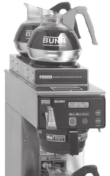
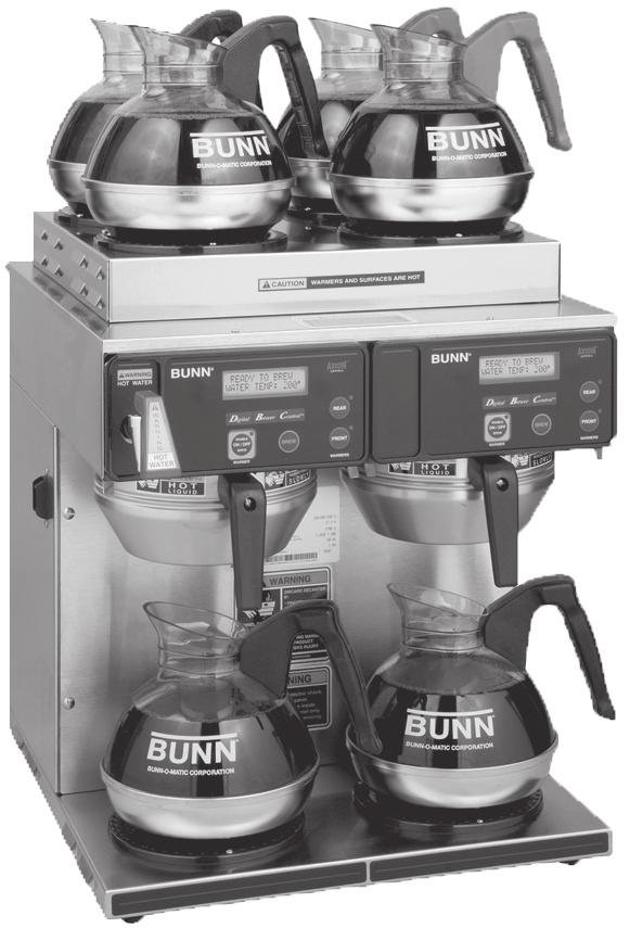
 AXIOM (4/2 Twin) approx. dimensions (H 19.1 x W 16.4 x D 17.7) AXIOM (0/6 Twin) approx. dimensions (H 20.5 x W 30.3 x D 17.")
4 Installation Site Requirements Space Counter able to support the weight of the equipment AXIOM (2 top warmers) approx. dimensions (H 18.9 x W 8.5 x D 17.7) AXIOM (3 lower warmers) approx. dimensions (H 16.8 x W 16.5 x D 17.7) AXIOM (4/2 Twin) approx. dimensions (H 19.1 x W 16.4 x D 17.7) AXIOM (0/6 Twin) approx. dimensions (H 20.5 x W 30.3 x D 17.7) Plumbing AXIOM (Single) 1/4 flare water connection AXIOM (Twin) 3/8 flare water connection A shut-off valve should be installed in the line before the machine Connected to cold water Dynamic water pressure 20-90psi, set to 50psi if regulator is needed Electrical 120VAC with a dedicated 20 amp circuit with proper breaker and receptacle 120/ VAC with a dedicated 20 amp circuit with proper breaker and receptacle 3 wire + ground (neutral, L1, L2, ground) Location of the Serial Number The machine s serial number is located on the data plate which is attached to the bottom of the front panel. The serial number begins with the letters AX. The complete serial number will need to be documented on all work orders and warranty tags. Install Preparation Step 1: Determine the electrical availability at site. Step 2: Using a volt meter check voltage and color coding for each conductor on wall outlet. Step 3: Factory installed power cord is 120VAC 15 amp. Unless ordered as VAC. Step 4: If VAC power is used remove front panel and locate the main terminal block. Remove the 120VAC power cord. Step 5: Feed new power cord thru the rear of the machine. Step 6: Install leads to the main field wiring terminal block. Step 7: Select desired voltage to be used by moving the selector switch. Switch is located in the upper most area of the front of the brewer with the front panel removed. Step 8: Place the AXIOM on a solid flat surface insuring it is level front to rear and side to side using a level, adjust legs as needed. Water Supply Install Step 1: Check dynamic water pressure, install a pressure regulator and set to 50 psi for pressures exceeding 90 psi or if excessive pressure fluctuations. Step 2: Flush water lines and filter if used Step 3: Install shut-off valve. Step 4: Attach the water line to the flare fitting of the machine. Step 5: Turn on water and check for leaks. 4 AXIOM Training Manual
5 Electrical Install An electrician must provide electrical service as specified in conformance with all local, state, and federal electrical codes. Step 1: Plug the unit into the power source. Initial Start-Up Step 1. Insert an empty funnel into the funnel rails. Step 2. Place an empty server under the funnel. Step 3. Connect the brewer to the power source. Step 4. Turn master on/off switch to the on position, located on the side or rear of the machine if equipped. Step 5. Press and release the BrewOn/Off Switch. Water will flow into the tank and stop when the tank is filled to its capacity. Display will show PLEASE WAIT...TANK FILLING until tank is filled with water. Step 6. Wait approximately twenty minutes for the water in the tank to heat to the proper temperature. Display will show READY TO BREW...WATER TEMP: 200 when tank is at operating temperature. Some water will drip from the funnel during this time; this is due to expansion and should not occur thereafter. Step 7. Place a small container beneath the faucet and open the faucet handle. Release it when you hear the tank refilling. Step 8. Water volumes and flow settings have been preset at the factory. Refer to adjustments for the Set Brew Ounces section of this manual should the volume need to be increased or decreased. Step 9. The brewer is now ready for user setup. Step 10. Repeat steps 5-9 for remaining side on Twins. Brew water temperature is factory set at 200 F (93.3 C). Areas of high altitude will require lowering this temperature to prevent boiling. This chart should be used as a guide when re-adjusting the brew water temperature. Altitude (Feet) Boiling point of water F C Recommended water temperature F C Bunn-O-Matic Corporation 5
6 Unit 2 Setup Unit Objectives Given a realistic scenario depicting a new site install, the learner will be able to install and setup the brewer for customer turnover without error. Given an installed machine, all the necessary tools and safety equipment, the learner will be able to set the machine up for initial operation. The learner will be able to enter programming. The learner will be able set the appropriate brew ounces. The learner will be able to calibrate the sprayhead flow rate. The learner will be able to enable BrewLOGIC and explain when it may be necessary.
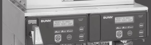
7 Setup and Programming As with all BUNN digital brewers the equipment has been designed for ease of use for both the end user as well as service technicians alike. End users have an opportunity to see the status of the equipment during idle time or during a brew cycle. It is technician friendly, as with any LCD display equipment BUNN manufactures, allowing for step by step calibrations, diagnostic functions as well as quick adjustments to name a few. The AXIOM has gone one step beyond, by providing cutting edge technology by monitoring outflow rates of water exiting the brew tank therefore allowing the control board the opportunity to adjust pot levels by increasing or decreasing the brew time needed during a brew cycle. Resulting in perfect pot levels every time. User Interface (Programming) Left Hidden Button LCD Display Right Hidden Button BUNN REAR FRONT WARMER WARMERS Digital Display: The display shows the various functions. Brewer Control Right Hidden Button: This is used to access the program mode and is also used to step forward through the menu. Left Hidden Button: This is used to step backwards through the function list. Digital (lower left under the display): This is used to select options that appear on the display during programming. Brewer (center under the display): This is used to select options that appear on the display during programming. Control (lower right under the display): This is used to select options that appear on the display during programming. Programming Lockout If the programming cannot be accessed, then the programming lockout switch is in the Disable position. The switch is located on the control board. Remove the top panel, locate the switch and place it into the Enable position. Bunn-O-Matic Corporation 7
8 Programming Menus The programming menus for the AXIOM are divided into three levels. Level 1, (BrewWIZARD ), allows for basic brewing adjustments. Level 2 is used for more advanced brewing adjustments in addition to supporting service and diagnostic functions. The final level of programming, Level 3, is where you can find advanced screens such as; Cal Temperature, Lime Adjust, and Calibrate LP1-LP2. While in programming you may exit and save any changes you have made by pressing and releasing the Enable On/ Off switch located on the front panel. Level 1 Programming (BrewWIZARD ) Press and hold the right hidden switch until the screen reads Brew Lockout? to enter programming. BREW LOCKOUT? NO DONE YES This function will lockout an operator if a predetermined temperature has not been achieved message will read Brew temp to low please wait heating. BREW OZ: 64.0 (-) DONE (+) This function allows the operator to adjust the brew volumes for the various sizes of holding vessels. BREW METER This function allows the operator to adjust the brew strength/extraction time setting 1 is non pulse setting, 14 being the highest setting using pulse brew. ENABLE ADS? NO DONE YES This screen allows the operator to utilize the screen for advertising; a tag card can be programmed with a message. ENTER SERVICE #? NO YES This function allows the operator to enter in a telephone number to call if service is needed. This number will be displayed anytime a fault message appears. EXITING BrewWIZARD This display is a prompt to advise you that you are exiting Level 1 programming. Level 2 Programming Level 2 programming can only be accessed by scrolling through Level 1 programming. ENTER PASSWORD This function allows the operator to enter a 3 digit code to password protect Level 2 programming. SET PASSWORD This function allows the operator to set a 3 digit code to password protect Level 2 programming. SET LANGUAGE NO YES This function allows the operator to choose between English, Spanish and French. UNITS METRIC DONE ENG This function allows the operator to choose between English or Metric. 8 AXIOM Training Manual
9 SET TEMP 200 O (-) DONE (+) Adjust the target temp of the Brew tank. Range of 185 F to 205 F. SET READY 195 O (-) DONE (+) This function sets the minimum temperature to start a brew cycle (BREW LOCKOUT). Range of 2 F min. to 20 F max. below the Set Temp. ENTER ASSET #? NO YES This display allows an optional asset number or tracking number to be assigned. SET PULSE BREW? NO YES This function allows the sprayhead to pulse on and off during the brew cycle. DRIP TIME 0:30 (-) DONE (+) This function will adjust the amount of time the display will read Dripping after a brew cycle is completed. ENABLE CLEAN NO DONE YES This display allows for a cleaning alert to be displayed (range of 1 to 30 days). Enabl Energy Savr NO DONE YES This function allows the tank heater(s) to run at a reduced rate during idle time. Enable Fresh Timer NO DONE YES This function allows a Freshness Alert message to display when a pre determined time has elapsed from the last brew. Range hrs. ENABL WARMER OFF NO DONE YES This function allow for auto warmer turn off after a pre determined time has been entered. Range 15 mins. To 6.0 hours. XXX REFILL 155 (-) DONE (+) This function adjusts sensitivity of the refill circuit. ENABLE BrewLOGIC NO DONE YES This function allows the brewer to be calibrated in high lime locations and compensate automatically as deposits build up in the equipment. SPRAY OZ/M: 25.0 (-) DONE (+) This is used to tell the internal controller how fast the water is flowing. CALIBRATE FLOW? NO YES BREW COUNTERS? NO YES This function provides a 60 second test mode to capture water from the sprayhead. This measurement will then give you the numbers to enter into the SPRAY OZ/M: xx screen above. Will not display when BrewLOGIC is enabled. Tracks the total number of brew cycles completed. Bunn-O-Matic Corporation 9
10 SERVICE TOOLS? NO YES Allows the testing of individual components and the ability to check the membrane switches for proper function. FACTORY DEFAULTS NO YES Reset all of the previously entered brew settings, ad message, calibrations, etc. Level 3 Programming To access Level 3 programming press and hold the right hidden button, until the screen reads Cal. Temperature, while on the Enter Password screen in Level 2 of programming. CAL TEMPERATURE NO SENSOR? YES % Lime Adjust OFF (-) DONE (+) This function allows the operator to recalibrate the CPU to the temperature thermistor. This must be preformed when you replace a CPU or a thermistor. This function allows for automatic adjustment of brew cycle times based on the output of the sprayhead. LP1 LP2 OZ 4.50 (-) DONE (+) SPRAY OZ/M: 25.0 (-) DONE (+) CALIBRATE FLOW? NO YES This function is used for calibration of the water volumes from the long level probe to the short level probe. This is used to tell the internal controller how fast the water is flowing. This function provides a 60 second test mode to capture water from the sprayhead. This measurement will then give you the numbers to enter into the SPRAY OZ/M: xx screen above. Will not display when BrewLOGIC is enabled. Machine Setup Brew Oz. It is necessary to setup the desired Brew Oz., due to the different size containers available in the market. To convert liters to ounces use this simple math equation. Liters X 33.9 = ounces For example if you were using a 3.0L airpot this is what your equation would look like. 3.0 X 33.9= rounded up to 102 fluid US ounces. Step 1: Enter programming Level 1, (BrewWIZARD ). Step 2: Scroll to the Brew Oz. screen. BREW OZ: 64.0 (-) DONE (+) Step 3: Use the (-) or (+) to enter Oz. the desired ounces for the container to be used. 10 AXIOM Training Manual
11 Calibrating Flow Rate Prior to programming the machine or brewing any coffee a flow rate calibration must be done. Flow rates will vary from machine to machine, location to location, even from one end of a building to another. Step 1: Enter Level 2 programming. Step 2: Scroll to the Calibrate Flow screen. This test is used to capture water from the sprayhead during a pre-determined 60 second dispense valve cycle. CALIBRATE FLOW? NO YES Step 3: Ensure the sprayhead and funnel are in place and put a container, measuring pitcher or server, underneath the funnel, select Yes. CONTAINER RDY? QUIT YES Step 4: To activate the flow rate check, press the Brew button. Step 5: The valve will open for 60 seconds. Once all of the water has dripped out, use the (-) or (+) buttons to input the volume collected and select Done. ENTER OZ: 24.5 (-) DONE (+) It is very important to be accurate when performing this test as it will control the pot level during normal operation. Enable BrewLOGIC (Optional) BrewLOGIC is a system that monitors output of water flow from the tank. This can be helpful when the equipment is placed in a high lime environment. As the flow rate begins to slow the system will compensate by increasing brew times as needed to maintain the proper pot levels. If enabled, the Calibrate Flow screen will not be visible. Step 1: Ensure the brewer is in it s final location and is level. Step 2: Enter Level 2 programming. Step 3: Scroll to Enable BrewLOGIC and select Yes. ENABLE BrewLOGIC NO DONE YES Step 4: On the Calibrate Now? screen select Yes. CALIBRATE NOW? NO YES Step 5: The display will now read Too Hot-Will Cool Tank Now, the change to Press Brew When Ready, (with brew funnel and container in place). The tank temperature must be in this range 130ºF to 170ºF, to perform the calibration. TOO HOT - WILL COOL TANK NOW Step 6: The display will read Cooling Tank Please Wait. Once the tank temperature is within the acceptable range the display will read, Container Ready?. Place an empty container beneath the funnel and select Yes. CONTAINER RDY? QUIT YES Bunn-O-Matic Corporation 11
12 Step 7: The display will read Calibrate Spray, press brew start the calibration. CALIBRATE SPRAY PRESS BREW START Step 8: WaitingTilCycle 4 the display will indicate cycles complete. WaitingTilCycle4 CYCLE 1 COMPLETE Step 9: Use the Digital (-) switch and Control (+) switch to adjust total volume captured. Press Done when finished. ENTER OZ: 24.5 (-) DONE (+) Spray OZ/M: XX.X LP1-LP2 OZ XX.X Lime Adjustment The % Lime Adjust menu is an adjustable percentage that you can modify to allow for lime compensation (flow-rate) when BrewLOGIC is enabled. The % Lime Adjust menu can be found in level 3 programming. The default value for Lime Adjust is set at 10%. % LimeAdjust ON ( - ) DONE ( + ) Smaller Percentage - less tolerant of the sprayhead flow-rate before compensation of brew time. Higher Percentage - more tolerant of the sprayhead flow-rate before compensation of brew time. To Access and Modify the Lime Adjust: 1. Enter level 2 programming by depressing the right hidden button for 5 seconds. This display screen should read Enter Password. 2. Press and release the right hidden switch until the display screen reads Enter Password. 3. Press and hold the right hidden switch until the display screen reads Calibrate Temp Sensor?. Once this occurs, you have reached level 3 programming. 4. Press and release the right hidden switch until the display screen reads % Lime Adjust. 5. Use the Digital ( - ), Brewer (Done), and Control (+) switches to make adjustments to this setting. Calibrating the Temperature Sensing Probe Note: Calibrating the temperature sensing probe (thermistor) should be done when replacing the CBA or thermistor. Allow the tank to heat the water to the ready temperature. No tests should be taken while the tank is heating as the tank temperature must be stable before any readings are recorded. Step 1: Remove the top panel of the machine. Step 2: Gain access to the water in the tank, the thermistor grommet can be removed (keep the thermistor in contact with the water.) Step 3: Place the probe of a digital thermometer into the water and measure the temperature. Step 4: Verify and record the temperature of the water. Step 5: Access level 3 programming and navigate to Cal Temperature Sensor? menu CAL TEMPERATURE screen. Select Yes. Step 6: Use the Digital (-) and Control (+) switches to enter the temperature that you NO SENSOR? YES recorded from the digital thermometer reading. 12 AXIOM Training Manual
13 Setting the Refill Threshold The refill setting in programming is a conductivity based system. It is a reading that is generated by the liquid level probe and the conductivity of the water in the tank has a total range of (this can be viewed on the Refill program screen). The lower the reading, the more conductance is being sensed. Conversely, the higher the reading, the less conductance. Theoretically it would read 0 when the probe touches the water, and 255 when it is not touching the water. However, due to water conditions and conditions in the tank, it may not have these exact readings. The programmable portion of the system is the switching point (or threshold). This is typically set to 155 (your default value). When the probe reading is less than this programmed number, it will be viewed as not requiring water from the refill system. When it is the number or greater, it will be viewed as needing water. If this threshold is causing problems, there s a simple way to determine the optimum switching point. Step 1: With water known to be touching the liquid level probe, record the probe reading that is present on the Refill program screen (it will show the programmed threshold and the actual reading, here we want the actual reading). Step 2: Now create a situation where it is known the water is not touching the probe (can raise the probe out of the tank). Record the probe reading. Step 3: With the 2 readings, set the programmed threshold to be exactly half-way Actual Reading Default Reading between the 2 numbers. XXX REFILL 155 (-) DONE (+) Bunn-O-Matic Corporation 13
14 Unit 3 Machine Composition Unit Objectives Given a realistic scenario in which the learner has access to the machine s internal components the learner will understand the composition and functions of the brewer. Given a realistic scenario requiring the learner to access the internal components of the machine the learner will be able to remove the front panel and top cover. The learner will disconnect the electrical and water supply. The learner will remove the front panel and top cover. Given an operating machine the learner will be able to give a general explanation of how the unit operates. The learner will be able to identify the functions of the main control board and identify the components that correspond to each triac. The learner will be able to identify the components and functions of the filling system. The learner will be able to identify the components and functions of the heating system. The learner will be able to identify the components and functions of the dispensing system. The learner will be able to identify the components and functions of the coffee holding system.

15 Machine Composition Exterior Overview Product Outlets and Removable Parts Faucet assembly Sprayhead Funnel Server User Interface (Operating) The user interface on the AXIOM consists of a membrane switch adhered to the front of the brewer. The membrane is connected to the main control board by a ribbon cable. This membrane allows the user to select a brew cycle in addition to control the warmer plates depending on model type. Faucet Funnel Sprayhead Server The display is also located in the front of the machine it is mounted to the main board. By showing what the status of the machine the display aids the operator and technicians. BUNN REAR FRONT WARMER WARMERS Enable Brew On/Off Switch Brew Switch Warmer Switches Enable Brew On/Off Switch: Pressing the Enable Brew On/Off switch (indicator on) supplies power to the brew station warmer, enables the brew circuit, and energizes the tank refill circuit. Pressing the switch again (indicator off) stops tank refilling and brewing and de-energizes the brew station warmer. Stopping a brew cycle after it has been started will not stop the flow of water into the server until the brew funnel is empty. Note: Hot water will be available at the faucet in a limited amount when the Enable Brew On/Off switch is in the Off position because the tank will not refill. Brew Switch: Momentarily pressing and releasing the switch starts a brew cycle when the Enable Brew On/Off indicator is on. Warmer Switches: Pressing any additional warmer switch so that the indicator is on, supplies power to the associated warmer. Note: APS and TC models have no warmers. Bunn-O-Matic Corporation 15


16 Accessing the Inside of the Brewer The majority of service work done on the AXIOM brewer will require the service technician to access the inside of the unit. The brewer has two removable panels, the top panel and front panel. Depending on the service required one or both of these panels may need to be removed. To work safely the power should disconnected prior to removing the panels. Once removed the brewer may be reconnected to troubleshoot the machine. Top Panel: The top panel is secured by one screw, to remove the panel remove the screw and while lifting the top slightly from the front push lightly towards the rear you can then completely remove. Front Panel: To remove the front panel, move the server and brew basket and set aside. Remove the four screws holding the front panel on and slide panel out. Machine Function and Operations Transformer Main Control Board The main control board is the brain of the brewer. In the digital AXIOM series brewer the control board is the single component that contains all of the programming software, it interprets all data it receives from the level and temperature sensors and opens or closes various components to complete a brew cycle. In a digital brewer the main control board takes the place of the liquid level board, timer board, and the mechanical thermostat. Filling System Tank Heater Relay The fill circuit consists of 120VAC inlet solenoid 2 Fill probes (referred to as Short LP1 and Long LP2) The fill system maintains the level of water in brew tank. Anytime water is drawn from the tank the fill circuit activates to refill the tank. Copper Line Water enters the brewer through the water supply line it then enters the chassis thru a copper line that is attached to the inlet solenoid. When the water enters the inlet valve it must first flow past a fine mesh screen housed within the valve, this mesh screen is designed to keep large particles of foreign material from entering the valve. Inlet Solenoid Flow Control Body Flow Control Washer Strainer Fill Tube Inlet Solenoid The 120VAC inlet solenoid is activated by the control board anytime the brewer calls for water. The inlet solenoid is energized to allow water to flow under line pressure. It then enters the tank through a silicone hose attached at the base of the tank. 16 AXIOM Training Manual
17 The control board monitors the level of water in the tank through a low voltage level probe (LP2 Probe) mounted to the top of the tank. When water touches the LP2 probe, the control board grounds a low voltage AC signal to the tank through minerals in the water and the inlet solenoid is de-engergized. A relay on the CBA closes it s contacts to complete the heating circuit and the heating element(s) will now receive voltage in order to heat the water in the tank. When the CBA detects water has reached ready temperature with the use of a thermistor, the tank will fill to LP1 probe level. The heating circuit will remain closed until water reaches the set tank temperature. Heating System The heating system consists of: Water tank Heating elements Triacs Temperature Sensor Blanket Warmer LP1 Probe LP 2 LP 1 Thermistor LP2 Probe The heating circuit maintains the water in the tank at a preset temperature; this insures the water is always ready for brewing. Water for brewing is contained in a 200 oz. Stainless steel tank. This tank contains 2 heating elements that are powered by the incoming line voltage to the machine. Both heating elements are controlled by a relay mounted on the main control board. The high limit thermostat is located inside the top cover on the front of the tank, the limit thermostat will interrupt the heating circuit should the tank overheat. The control board monitors the water temperature with the use of a thermistor that is in contact with the water. When water in the tank drops below the ready temperature, the control board interprets the value of the thermistor and in return will activate the heater relay to bring the tank temperature back up to the set tank temperature. 2268W Heating Element (Dual Volt Models) 1425W Heating Element The blanket warmer provides a low consistent heat around the tank at the point of the temperature sensor. This additional heat aids the heater circuit by reducing the number of on/off cycles, thereby extending the life of the relay contacts and the heater Watt Blanket Heater High Limit Thermostat Bunn-O-Matic Corporation 17

18 Dispensing System The dispensing system consists of: Brew valve Sprayhead The dispensing system is what makes the brewer a coffee brewer. It dispenses the hot water over a bed of coffee grounds to create the product. The AXIOM uses a gravity dump valve system. During the brew cycle the brew valve opens allowing water to flow from the tank and out the Sprayhead. The control board opens and closes this valve according to perimeters programmed into the control board based on a specific recipe. While the dispensing system works much the same way as any other BUNN gravity feed brewer. One major difference can be found that s cutting edge technology to combat lime scale buildup within the hydraulic system. BrewLOGIC utilizes 2 liquid level probes, as discussed earlier the long (LP2) probe performs the standard tank fill when the control board calls for water. When BrewLOGIC is activated and calibrated as earlier discussed the tank water is monitored for flow rate out of the sprayhead using a mathematical algorithm that was determined during calibration. If the flow rate from the sprayhead is too slow or too fast within the first two cycles, the control board will adjust the overall brew time to compensate. Dispense Solenoid Dispense Solenoid Hot Water Faucet Sprayhead 18 AXIOM Training Manual
19 Unit 4 Preventive Maintenance Unit Objectives Given a realistic scenario depicting a machine requiring a preventive maintenance, the learner will be able to identify which elements of a component need to be serviced without error. Given a machine, all the necessary tools and safety equipment, the learner will be able to identify the components that need to be serviced for the PM.
20 Preventive Maintenance In order to maintain proper operation and long service life BUNN recommends performing the preventive maintenance every 6 months. Individual customers will vary with some customers choosing not to receive preventive maintenance. Tools Required: 2 Flat head screwdrivers (1 small, 1 medium) Adjustable wrench Needle nose pliers Deliming tool (BUNN P/N: ) Prior to servicing the brewer: Disconnect the electrical supply Shut off water supply PM Steps Step 1: Remove probes from tank lid. Remove top and front access panels Drain tank using drain hose located behind front panel. Caution Hot Water!! Remove thermistor probe (temp probe) from the top of the tank. Clean and inspect Remove liquid level probes (2) from tank lid clean and inspect Reassembly is the opposite of disassembly Step 2: Rebuild brew valve, clean outlet fittings at tank. Remove wire leads from brew valve Carefully remove silicon hose from brew valve Remove mounting nuts Remove 4 screws from valve Replace plunger, spring and rubber seat using rebuild kit, (BUNN P/N: ) Carefully remove the silicon hoses from the outlet tank fittings Clean fittings using deliming tool (long end) or suitable tool Reassembly is the opposite of disassembly Step 3: Rebuild hot water faucet. Replace hot water seat cup by unscrewing the bonnet assembly Remove old seat cup Install new seat cup, (BUNN P/N: ) Reassembly is opposite of disassembly Step 4: Clean and inspect Sprayhead clean spray head fitting. Clean and inspect Sprayhead Clean Sprayhead fitting using deliming tool Step 5: Inspect brew funnel for missing or loose parts. Step 6: Inspect water connection points for signs of leakage. Step 7: Inspect power cord. Step 8: Return AXIOM to service. Turn on water supply and check for leaks Plug AXIOM in at wall receptacle Allow tank to fill and heat to operating temperature 20 AXIOM Training Manual
21 Step 9: Calibrate Sprayhead. Enter Level 2 programming. Scroll to the Calibrate Flow screen. This test is used to capture water from the sprayhead during a pre-deter mined 60 second dispense valve cycle. CALIBRATE FLOW? NO YES Ensure the sprayhead and funnel are in place and put a container, measuring pitcher or server, underneath the funnel, select Yes. CONTAINER RDY? QUIT YES To activate the flow rate check, press the Brew button. The valve will open for 60 seconds. Once all of the water has dripped out, use the (-) or (+) buttons to input the volume collected and select Done. ENTER OZ: 24.5 (-) DONE (+) Bunn-O-Matic Corporation 21
22 Unit 5 Troubleshooting Unit Objectives Given a realistic scenario depicting a broken machine, the learner will be able to effectively troubleshoot, diagnosis, and repair the problem returning the machine to normal operation. Given a machine displaying an error message, all the necessary tools and safety equipment, the learner will be able to access the software and diagnosis the problem. The learner will be able to access the programming menu. The learner will be able to navigate to the Service Tools menu. The learner will be able use the Service Tools menu to test inputs or outputs. Given a list of error messages and issues, the learner will be to identify the probable cause of the message or issue. Given a brewer with a defective component, the learner will be able to test the component to determine the cause of the defect.
23 Troubleshooting and Repair The AXIOM brewer series features onboard troubleshooting diagnostics. Since all of the brewers components are controlled or activated by the control board all components can easily be activated for testing by user interface. Service Tools The Service tools option is located in level 2 programming. Enter level 2 programming by pressing and holding the right hidden switch for approximately 5 seconds. Scroll to level 2 Service Tools using the right hidden switch. Press the Control button to select Yes. This will enter the Service Tools feature. SERVICE TOOLS? NO YES In the Service Tools selection there are 5 screens available, three of which are read only. By selecting Yes, when given the option, you will enter that test function, and by selecting No you will move to the next test. TEST OUTPUTS? NO YES Test Outputs tests supplies voltage to load components in the brewer. TEST SWITCHES? NO YES Test Switches tests the inputs from the membrane switches. LP1 LP2 4 DONE 3 Read Only, indicates if water is present on one or both Level Probes. SPRAY OZ/M: 23.4 DONE LP1 LP2 OZ 4.09 DONE Read Only, indicates the current calibration of the sprayhead. Read Only, shows the total volume of water between the Short and Long probes. Test Outputs Test Outputs the following components can be activated for troubleshooting. BREW VALVE REFILL VALVE MAIN WARMER LEFT WARMER ON NEXT OFF ON NEXT OFF ON NEXT OFF ON NEXT OFF LEFT FRONT WARMR LEFT REAR WARMER R FRONT/TOP WARMR RIGHT REAR WARMR ON NEXT OFF ON NEXT OFF ON NEXT OFF ON NEXT OFF TANK HEATER RELAY ON NEXT OFF Bunn-O-Matic Corporation 23
24 Test Switches TEST SWITCHES? NO YES NOTHING PRESSED Test Switches this test allows for testing of all switches on the Membrane touchpad when a button is depressed the display will read the button selected. If Nothing Pressed appears on the display while depressing the switch the Control Board is not receiving a signal. BUNN REAR FRONT WARMER WARMERS Service Fault Messages The AXIOM brewer features several error messages for problems occurring within the machine. These error messages will be shown on the display. TEMPERATURE TOO LOW Indicates water temperature has not met the ready temperature (Brew lockout enabled). HEATING TIME TOO LONG Indicates Tank heater failure or Control board/thermistor failure. FILL TIME TOO LONG Indicates water shutoff, supply line to small or obstructed, inlet solenoid failure, on/off switch (enable/disable) switch in off position. TEMP SENSOR OUT OF RANGE If the control board loses contact with the temperature sensor or senses shorted connection it will display this message. CHECK SPRAYHEAD FOR LIME Indicates that the flow is being restricted. Check Fittings For Lime alternates with this screen. WARNING INACCURATE FLOW WARNING Repair VERY LOW FLOW Indicates that the flow is being severely restricted. Too Much Lime Please Repair alternates with this screen. Indicates that the flow is extremely low and the blockage needs to be removed. Please alternates with this screen. 24 AXIOM Training Manual
 menus.")

25 Troubleshooting Components Membrane Switch The membrane switch is located on the front face plate. Test Procedures: There are two methods for testing the membrane switch. The easiest method is to use the built in test mode. Refer to the programming section in this manual to access the Service Tools (Test Switches) menus. If for some reason you can t get into the program mode, or brewer won t power up, you can test it with an ohmmeter or continuity tester. Refer to the schematic to trace the appropriate pins. Wrap a thin paper clip around each meter lead and extend past the tip by ¼ - ½. You may need to sand off the clear coating on some clips! NOTE: Pin 1 is the static shield & will not provide a reading to the other pins. There are two commons in this circuit, pins 9 & 10. Disconnect brewer from power source before disconnecting ribbon cable from control board. Brew Valve The brew valve is located inside the top cover behind the front face plate. Test Procedures: 1. Enter level 2 programming to access Service Tools/Test Outputs/Brew Valve. 2. Be sure brew funnel & server are in place before activating valve. 3. Check the valve for coil action. Turn on the valve with the test mode. Listen care fully in the vicinity of the brew valve for a click as the coil pulls the plunger in. If no sound is heard as described, proceed to #4. If the sound is heard as described, there may be a blockage in the valve, hose, tank, or sprayhead. Disconnect the brewer from the power source. Remove the valve and inspect for blockage, and de-lime all related areas. 4. Connect the voltmeter leads to the coil terminals. Turn on the valve with the test mode. NOTE: Due to the internally rectified coil, the indication will be 120VAC all the time. Set the meter to DC volts. The indication should be 170VDC when activated. If the polarity of meter leads are reversed, reading will indicate -170VDC. (Double these readings for 240 volt coils) If voltage is present as described, but no coil action is observed, brew valve is defective. Replace valve and test again to verify repair. If voltage is not present as described, refer to Wiring Diagrams and check the brewer wiring harness. Also check the control board and switch for proper operation. Liquid Level Probe System The level probes are located inside the tank lid. Test Procedures: 1. Enter programming level 2, scroll to Refill. NOTE: This screen only reads the long probe (blue wire) and is used for setting the refill conductance threshold. Alternate: Scroll to Service Tools. Then scroll to LP1 & LP2. LP1 = short probe, LP2 = long probe. 2. A high reading (approximately 255) indicates water is not touching, or not conductive enough to ground the circuit. A low reading (0-2) indicates the probe is grounded. Due to the internally rectified coil, do not attempt to test this type of coil with an ohmmeter. The reading will open or very high resistance, depending on the polarity of your meter leads. Bunn-O-Matic Corporation 25

. If voltage is not present as described, proceed to #4. 4.")
26 Temperature Probe The temperature probe is inserted through the tank lid assembly. Test Procedures: 1. Connect the brewer to the power source. 2. With a DC voltmeter, check voltage across the two wires at J9 on control board (Blackprobe to black wire, red probe to white wire. The indication should be aproximately between 4vdc cool to 1vdc at ready temperature. 3. Disconnect the brewer from the power source. If voltage is present as described, circuit is working correctly, check high limit thermostat (and TCO on 230V models). If voltage is not present as described, proceed to #4. 4. Disconnect temperature probe from J9 on control board. Check the resistance across the two terminals of the temperature probe. The indication should be approximately between 10.5K cool to 870 at ready temperature. If resistance is to specification, replace the control board. If resistance is not to specification, replace the temperature probe. High Limit Thermostat The limit thermostat is located inside the top cover on the front side of the tank. Test Procedures: 1. Disconnect the brewer from the power source. 2. Disconnect the wires from the limit thermostat. 3. With an ohmmeter, check for continuity across the limit thermostat terminals. If continuity is present as described, the limit thermostat is operating properly. If continuity is not present as described, replace the limit thermostat. Refill Valve The refill valve is located inside the front of the brewer. Test Procedures: 1. Enter programming level 2, scroll to Service Tools then scroll to Refill Valve. 2. Briefly activate the refill valve in the test mode. With a voltmeter, check the voltage across the coil wires. 3. The indication must be 120 volts ac for two wire 120 volt models and three wire 120/ volt models or 230 volts ac for two wire 230 volt models. If voltage is present, proceed to # 4. If voltage is not present, refer to Wiring Diagrams and check main wiring harness. If harness checks ok, replace control board. 4. Check the refill valve for coil action. Briefly activate the refill valve in the test mode and listen carefully near the refill valve for a clicking sound as the magnetic coil pulls the plunger in. If the sound is heard as described and water will not pass through the refill valve, there may be a blockage in the water line before the refill valve or, the solenoid valve may require inspection for wear, and removal of waterborne particles. If the sound is not heard as described, proceed to # 5. Flow Control Body Flow Control Washer Strainer 5. Disconnect the brewer from the power source. 6. Check for continuity across the refill valve coil terminals. If continuity is not present as described, replace the refill valve. If continuity is present as described, there could be some debris in the valve. 26 AXIOM Training Manual
 or red wire (120/208-240V Models) from the terminal block and black wire from the control board. Connect brewer to the power source.")

27 Tank Heaters The tank heaters are located inside the tank and secured to the tank bottom. Test Procedures: 1. With a voltmeter, check voltage across the white wire (120V Models) or red wire (120/ V Models) from the terminal block and black wire from the control board. Connect brewer to the power source. The indication must be 120 volts ac for two wire 120 volt models or volts ac for three wire 120/ volt models (during a heating cycle). 2. Disconnect the brewer from the power source. If voltage is present as described, proceed to #3. If voltage is not present as described, refer to the Wiring Diagrams and check wiring harness. If harness checks ok, replace control board. 2268W Large Dia. HEATER RESISTANCE 1425W-120V W-240V W-240V W-200V W-240V W-240V 6.35 TERMINAL TO SHEATH - INFINITE (OPEN) 1425W Small Dia. 3. Disconnect the wires from the tank heater terminals. 4. Check resistance value across tank heater terminals and compare to chart. If resistance is present as described, reconnect the wires, the tank heater is ok. If resistance is not present as described, replace the tank heater. NOTE- If any resistance is read between sheath and either terminal, remove and inspect heater for cracks in the sheath. Blanket Warmer The blanket warmer is wrapped around the tank assembly. Test Procedures: 1. Disconnect the brewer from the power source. 2. With a voltmeter, check voltage across the two wires at the warmer element with the ON/OFF switch in the ON position. Connect the brewer to the power source. The indication must be 120 volts ac for two wire 120 volt models and three wire 120/208 and 120/240 volt models, or 230 volts ac for two wire 230 volt models. 3. Disconnect the brewer from the power source. If voltage is present as described, proceed to #4. If voltage is not present as described, refer to Wiring Diagrams and check wiring harness. 4. Check the resistance across the two terminals on the blanket warmer. Refer to chart below. If resistance is to specification, reconnect the two wires to the blanket warmer. If resistance is not to specification, replace the blanket warmer. WARMER RESISTANCE 50W-120V W-220V Bunn-O-Matic Corporation 27
28 Troubleshooting the Refill Circuit Problem Probable Cause remedy Will not refill 1. Power off to brewer Press OFF/ON switch on control panel to determine if power is ON. 2. Water shut off Make sure water is ON. 3. Error Message Brewer has shut down due to malfunction (See Service Fault Messages in this manual) 4.ON/OFF Switch (If equipped) Make sure ON/OFF Switch is ON and indicator is lit. 5. Lime build up on Probe(s) Remove Level Probe and check for lime deposits on tip. Clean and reinstall. 6. Refill Valve or Control Board Enter Service Tools and test the Refill Valve. As the refill valve activates, check the voltage across the coil wires. If voltage is present (120V), refer to wiring diagram and check the main wiring harness. If main wiring harness checks ok, the Control Board might need replacement. Refill does not shut off Power ON 1. Lime build up on probe Remove Level Probe and check for lime deposits on tip. Clean and reinstall. 2. Water Level Sensing System Replace control board 3. Refill valve or control board Enter Service Tools and test the Refill Valve. As the refill valve activates, check the voltage across the coil wires. If voltage is present (120V), refer to wiring diagram and check the main wiring harness. If main wiring harness checks ok, the Control Board might need replacement. 1. Refill valve Refill does not shut off Power OFF Troubleshooting the Heating Circuit Problem Probable Cause remedy Water does not heat to proper temperature 1. Display s error message Brewer has shut down due to malfunction. See Service Fault Messages section in this manual. IMPORTANT: Make sure no temperature tests are taken before the display reads ready. Tank temperature must be stabilized before readings are taken. 2. Water not touching main (short) level probe Remove level probe and grommet. Look into hole on tank lid. Water must be within approximately one inch from top of tank. 3. Water Level Probe Sensing System Check refill circuit. Heaters will not turn on if water is not grounding level probe. 4. Temperature Probe Check/replace 5. Limit Thermostat or Check/replace TCO 6. Tank Heater Check/replace Spitting or excessive steaming 1. Lime build up on tem- Inspect probe and tank assembly for excessive lime deposits. Delime as required. perature probe, tank or tank heater 2. Temperature Probe Check/replace 28 AXIOM Training Manual
29 Heating Circuit (cont.) Problem Probable Cause remedy Spitting or excessive steaming 3. Control Board Check/replace (cont.) Brewer is making unusual noises 1. Plumbing lines Plumbing lines should not rest on the counter top. 2. Water supply The brewer must be connected to a cold water supply. 3. Lime build up Remove the tank lid and clean inside of tank with a deliming agent, if necessary. Troubleshooting the Brewing Circuit Problem Probable Cause remedy Brew cycle will not start 1. Display s error message Brewer has shut down due to malfunction. See Service Fault Messages section in this manual 2. No water Water lines and valves to the brewer must be open 3. No power or incorrect voltage to the brewer Check for voltage across the terminals at the terminal block. 4. ON/OFF switch not in the ON position The indicator lamp must be lit 5. Low water temperature (Brew lockout is enabled) 6. Water not touching refill probe inside tank Allow brewer to heat until ready, or disable the brew lockout feature. Water must be in contact with refill probe before brew cycle will start. 7. Membrane Switch Check/replace 8. Dispense valve Check/replace 9. Control board Check/replace Consistently low beverage level in the dispenser or beverage overflows dispenser 1. Brew volume NOTE: Volume adjustments must be made with sprayhead installed. Calibrate Sprayhead 2. Lime build up Inspect the dispense valve and sprayhead for excessive lime deposits. Delime as required. 3. Dispense Valve Remove dispense valve and clear any obstructions. Rebuild or replace valve if necessary. Brew cycle starts, then aborts and returns to Main 1. Level probes shorted Ensure mylar shield(s) are installed on top cover screen after 20 seconds Dripping from sprayhead 1. Lime build up Inspect the tank assembly for excessive lime deposits. Delime as required. 2. Dispense valve Check/replace Weak beverage 1. Sprayhead A clean sprayhead must be used for proper extraction. Bunn-O-Matic Corporation 29
.")
30 Brewing Circuit (cont.) Problem Probable Cause remedy Weak beverage (cont.) 2. Water temperature Place an empty brew funnel on an empty decanter beneath the sprayhead. Initiate brew cycle and check the water temperature immediately below the sprayhead with a thermometer. The reading must not be less than 195 F (91 C). Adjust the temperature setting to increase the water temperature. 3. Filter type BUNN paper filters must be used for proper extraction. 4. Coffee grind A fine drip or grind must be used for proper extraction. 5. Funnel loading The BUNN paper filter must be centered in the funnel and the bed of grounds leveled by shaking gently. Dry coffee grounds remain in the funnel 1. Sprayhead Make sure sprayhead is present and holes are clear and unobstructed. 2. Funnel loading The BUNN paper filter must be centered in the funnel and the bed of grounds leveled by shaking gently. Low beverage serving temperature 1. Thermal server/airpot not preheated before brew cycle Preheat server with warm water before next brewing cycle. Triac Map Viewing the Control board as if were installed in the machine on the right vertical edge a series of 5 triacs can be found. They are labeled TH1 to TH5 with TH1 being located at the bottom of the board and TH5 at the top. 1: TH1 Left Front Warmer 2: TH2 controls Brew Solenoid Valve 3: TH3 Right Rear Warmer 4: TH4 controls Refill Solenoid Valve 5: TH5 Main Warmer 30 AXIOM Training Manual
31 -14 RELAY J1-1 J1-5 J1-10 J BLU BRN/ /BLU /RED YEL /VIO VIO /GRN LIMIT THERMOSTAT BLU-14 STATIC SHIELD SCHEMATIC WIRING DIAGRAM AXIOM "KEEP WARM" HEATER CONTROL SWITCH ASSY (NOTE ALL WARMERS ARE NOT AVAILABLE ON ALL MODELS!) -14 /GRN P2 BRN/ VIO YEL P3 P2 SOL TANK HEATER BRN/ VIO FRONT WARMER REAR WARMER -14 Model 20 RED-14 Model 35 BREW STATION WARMER /RED (CONTROLLED BY ON/OFF SW) REFILL DISPENSE YEL Model 15 GREEN MAIN ON/OFF SWITCH (Late 20 & 35 Models only) (LEFT WARMER) FRONT WARMER Model 20 & 35 /BLU (TOP OR RIGHT WARMERS) SOL P1 P1 L1 Model 15 L2 RED Model 35 P1, P2, & P3 ARE PINS OF A POLARIZED THREE-PIN CONNECTOR. N Model 20 Model 15 & 35 Model 20 J2-6 P3 /VIO /VIO REAR WARMER J2-10 J3-1 J3-3 J9-1 BRN GRN BLU B1 120V AC 2 WIRE 120/208V AC 3 WIRE 120/240V AC 3 WIRE SINGLE PHASE A6 D1 A3 D2 A4 D3 A5 B2 A2 A1 t LEVEL PROBE (SHORT) LEVEL PROBE (LONG) OPTIONAL DUAL TOP WARMER ASSY BRN/ 3 1 BLU/ CONTROL SWITCH ASSY CODES 2 WARMERS ON LEFT 2 WARMERS ON TOP 2 WARMERS ON RIGHT BREW STATION A3 A3 A3 LEFT FRONT A2 LEFT REAR A1 TOP FRONT A5 TOP REAR A6 RIGHT FRONT A5 RIGHT REAR A6 START BREW A4 A4 A4 LEFT HIDDEN B1 B1 B1 RIGHT HIDDEN B2 B2 B2 DIGITAL D1 D1 D1 BREWER D2 D2 D2 CONTROL D3 D3 D3 REAR FRONT Bunn-O-Matic Corporation 31
32 SCHEMATIC WIRING DIAGRAM AXIOM DV GRN L1 L2 RED N MAIN ON/OFF SWITCH (Late Models only) RELAY J1-1 J1-5 J1-10 J2-1 LIMIT THERMOSTAT -14 BLU-14 BLU BRN/ /BLU /RED YEL /VIO VIO /GRN STATIC SHIELD -14 TANK HEATER 1425W "KEEP WARM" HEATER CONTROL SWITCH ASSY (NOTE ALL WARMERS ARE NOT AVAILABLE ON ALL MODELS!) BLU-14 /GRN P2 BRN/ VIO YEL SELECTOR SWITCH /RED DISPENSE P3 P2 SOL BRN/ VIO YEL -14 /VIO-14 BREW STATION WARMER (CONTROLLED BY ON/OFF SW) FRONT WARMER REAR WARMER (LEFT WARMER) FRONT WARMER /BLU (TOP OR RIGHT WARMERS) TANK HEATER 2268W -14 REFILL SOL P1 P1 RED-14 P1, P2, & P3 ARE PINS OF A POLARIZED THREE-PIN CONNECTOR. J2-6 P3 /VIO /VIO REAR WARMER B1 A6 D1 A3 D2 A4 D3 A5 B2 A2 A1 J2-10 CONTROL SWITCH ASSY CODES J3-1 J3-3 J9-1 BRN GRN BLU 120V AC 2 WIRE + GND 120/208V AC 3 WIRE + GND 120/240V AC 3 WIRE + GND SINGLE PHASE t LEVEL PROBE (SHORT) LEVEL PROBE (LONG) 2 WARMERS ON LEFT 2 WARMERS ON TOP 2 WARMERS ON RIGHT BREW STATION A3 A3 A3 LEFT FRONT A2 LEFT REAR A1 TOP FRONT A5 TOP REAR A6 RIGHT FRONT A5 RIGHT REAR A6 START BREW A4 A4 A4 LEFT HIDDEN B1 B1 B1 RIGHT HIDDEN B2 B2 B2 DIGITAL D1 D1 D1 BREWER D2 D2 D2 CONTROL D3 D3 D3 32 AXIOM Training Manual
33 SCHEMATIC WIRING DIAGRAM AXIOM TWIN 2/2 L1 L2 N CONTROL SWITCH ASSY CODES 2 WARMERS ON LEFT 2 WARMERS ON TOP 2 WARMERS ON RIGHT BREW STATION A3 A3 A3 LEFT FRONT A2 LEFT REAR A1 TOP FRONT A5 TOP REAR A6 RIGHT FRONT A5 RIGHT REAR A6 START BREW A4 A4 A4 LEFT HIDDEN B1 B1 B1 RIGHT HIDDEN B2 B2 B2 DIGITAL D1 D1 D1 BREWER D2 D2 D2 CONTROL D3 D3 D RED-14 RED-14 LIMIT THERMOSTAT BLU BLU COUNTER (OPTIONAL) -14 TANK HEATER /GRN /BLU "KEEP WARM" HEATER /YEL BREW STATION WARMER 5 /BLU /RED BREW STATION WARMER /RED /GRN BRN (TOP WARMERS) GRN BLU LEVEL PROBE (SHORT) LEVEL PROBE (LONG) LEVEL PROBE (LONG) A 06/ BUNN-O-MATIC CORPORATION t t RED 120/208V AC 3 WIRE + GND 120/240V AC 3 WIRE + GND SINGLE PHASE MAIN ON/OFF SWITCH (Late Models only) GRN Earth Ground Chassis Ground -14 LIMIT THERMOSTAT BLU J1 TRM 1 TRM 2 COM N.O. 1 BLU COUNTER (OPTIONAL) -14 TANK HEATER /GRN /BLU BREW SOL "KEEP WARM" HEATER REFILL SOL J1 TRM 1 TRM 2 COM N.O. 1 BREW SOL REFILL SOL YEL 5 /BLU RED/ 10 /GRN CONTROL SWITCH ASSY 10 J2 J STATIC SHIELD (NOTE ALL WARMERS ARE NOT AVAILABLE ON ALL MODELS!) P3 P2 P1 P1, P2, & P3 ARE PINS OF A POLARIZED THREE-PIN CONNECTOR 5 STATIC SHIELD CONTROL SWITCH ASSY (NOTE ALL WARMERS ARE NOT AVAILABLE ON ALL MODELS!) B1 D1 A3 D2 A4 D3 A5 B2 B1 D1 A3 D2 A4 D3 A5 B2 LEFT RIGHT J3 J J3 J BRN GRN BLU LEVEL PROBE (SHORT) Bunn-O-Matic Corporation 33

34 Additional Resources Visit the BUNN Online Learning Center for technical information on BUNN equipment. Unit Objectives Go to URL: Go to the menu bar and place your cursor over Courses, then choose Commercial. Browse the list of available courses. From the course introduction, use the menu on the left to find instruction sheets, manuals, key learnings, checklists and updates on equipment. BUNN also has a wide range of instructional videos posted on the Online learning center and itunes. You may subscribe to these videos via , RSS, or as a podcast. After subscribing, you will be notified when a new video is posted. QR Code Reader For quick and direct access to technical resources on the BUNN Online Learning Center, you can download a QR- Reader application for your SmartPhone. Download QRReader Application for your SmartPhone. Open the QRReader application on your SmartPhone. Aim your SmartPhone Camera as if you are taking a picture of the QR code image. (image on the right) The QRReader Application will direct you to the BOLC, where you will have access to many resources relating to BUNN beverage equipment. Technical Service & Support Contact Information Technical Service Department can be reached at: (Operators are available from 6:30 am to 5:30 pm CT. Monday - Friday) Calls received after hours or weekends will go through our Telemessaging Service. You will then be connected to the first available service representative. tech.service@bunn.com Bunn-O-Matic Corporation, All rights reserved. Bunn-O-Matic Corporation Stevenson Drive - Springfield, IL Ph: (800) Fax (217)
Unit 3 Machine Composition
 Unit 3 Machine Composition Unit Objectives Given a realistic scenario in which the learner has access to the machine s internal components the learner will understand the composition and functions of the
BUNN TECHNICAL TRAINING. Dual SH BrewWISE DBC
 BUNN TECHNICAL TRAINING Dual SH BrewWISE DBC Index Unit 1: Installation Site Requirements...4 Location of the Serial Number...4 Water Supply Install...4 Electrical Install...4 Initial Start-Up...5 Unit
BUNN TECHNICAL TRAINING ICB
 BUNN TECHNICAL TRAINING ICB Index Unit 1: Installation Site Requirements...4 Location of the Serial Number...5 Water Supply Install...5 Electrical Install...5 Initial Start-Up...6 Unit 2: Setup Setup and
DISCONTINUED VERSION The information in this manual is no longer current.
 CDBC-MV, CDBCF-MV CDBC-MV, CDBCF APS-MV CDBC-DV, CDBCF-DV CDBC APS-DV CDBCF APS-DV (DV Models prior to Serial #CDBC024477) DISCONTINUED VERSION The information in this manual is no longer current. BUNN
ITB/ITCB/HV ICB/TWIN New Infusion Series
 ITB/ITCB/HV ICB/TWIN New Infusion Series SERVICE & REPAIR MANUAL BUNN-O-MATIC CORPORATION POST OFFICE BOX 3227 SPRINGFIELD, ILLINOIS 62708-3227 PHONE: (217) 529-6601 FAX: (217) 529-6644 54299.0000A 07/17
BrewWISE DBC BREWERS WITH SMART FUNNEL
 BrewWISE DBC BREWERS WITH SMART FUNNEL SERVICE & REPAIR MANUAL BUNN-O-MATIC CORPORATION POST OFFICE BOX 3227 SPRINGFIELD, ILLINOIS 62708-3227 PHONE: (217) 529-6601 FAX: (217) 529-6644 41746.0000D 04/10
ITB/ITCB/HV ICB SH/DV/TWIN New Infusion Series
 ITB/ITCB/HV ICB SH/DV/TWIN New Infusion Series SERVICE MANUAL INSTALLATION & OPERATING GUIDE BUNN-O-MATIC CORPORATION POST OFFICE BOX 3227 SPRINGFIELD, ILLINOIS 62708-3227 PHONE: (217) 529-6601 FAX: (217)
VP17A BUNN OPERATING & SERVICE MANUAL
 BUNN VP17A OPERATING & SERVICE MANUAL BUNN-O-MATIC CORPORATION POST OFFICE BOX 3227 SPRINGFIELD, ILLINOIS 62708-3227 PHONE: (217) 529-6601 FAX: (217) 529-6644 10860.0001C 9/00 1997 Bunn-O-Matic Corporation
BUNN OT & RT OPERATING & SERVICE MANUAL
 BUNN OT & RT! FUNNEL CTENTS ARE HOT CAUTI DISCARD DECANTER IF:. CRACKED. SCRATCHED. BOILED DRY. HEATED WHEN EMPTY. USED HIGH FLAME. OR EXPOSED ELECTRIC ELEMENTS FAILURE TO COMPLY RISKS INJURY PN: 658 1985
BUNN C, CT, CTF, CWT, CWTF, SINGLE CW, SINGLE CWF OPERATING & SERVICE MANUAL BUNN-O-MATIC CORPORATION.
 PN: 658! IF: BUNN C, CT, CTF, CWT, CWTF, SINGLE CW, SINGLE CWF CAUTION DISCARD DECANTER. CRACKED. SCRATCHED. BOILED DRY. HEATED WHEN EMPTY. USED ON HIGH FLAME. OR EXPOSED ELECTRIC FUNNEL CONTENTS ARE HOT
CWT TWIN CWTF TWIN CWTF TWIN-APS
 ! IF: ON T A N K OFF PN: 658!! IF: IF: ELEMENTS. CRACKED CWT TWIN CWTF TWIN CWTF TWIN-APS CW SERIES CW SERIES BUNN ON START CAUTION DISCARD DECANTER. SCRATCHED. BOILED DRY. HEATED WHEN EMPTY. USED ON HIGH
DUAL BREWER AUTOMATIC DB2A
 DUAL BREWER AUTOMATIC DB2A DB2A INSTALLATION REV -29-2006 INSTALLATION, OPERATION, AND TROUBLESHOOTING MANUAL FOR DB2A AUTOMATIC BREWER WITH WARMERS & POUR-OVER Model DB2A 8-1/2 W x 18 D x H 700 Total
QUICK B REW. DISCONTINUED VERSION The information in this manual is no longer current. OPERATING & SERVICE MANUAL
 TU3Q QUICK B REW DISCONTINUED VERSION The information in this manual is no longer current. OPERATING & SERVICE MANUAL BUNN-O-MATIC CORPORATION POST OFFICE BOX 3227 SPRINGFIELD, ILLINOIS 62708-3227 PHONE:
Unit 3 Machine Composition
 Unit 3 Machine Composition Unit Objectives Given a realistic scenario in which the learner has access to the machine s internal components the learner will understand the composition and functions of the
E N T E R P R I S E S INSTALLATION, OPERATION, AND SERVICE MANUAL FOR GK SERIES BREWERS
 N E W C O E N T E R P R I S E S INSTALLATION, OPERATION, AND SERVICE MANUAL FOR GK SERIES BREWERS Man Pt No 701278 050306 GKDF-4 GKF-3 Model Warmers Width Length Height Weight Watts Amps GKF-1 1 9-1/2"
TITAN DUAL TITAN SINGLE
 TITAN DUAL TITAN SINGLE SERVIE & REPAIR MANUAL BUNN-O-MATI ORPORATION POST OFFIE BOX 3227 SPRINGFIELD, ILLINOIS 62708-3227 PHONE: (217) 529-6601 FAX: (217) 529-6644 41747.0000A 11/08 2008 Bunn-O-Matic
C, CS, CT, CWTF, CRT, CRTF Series Including DV, MV, APS/TC/TS, Single CW & Twins
 C, CS, CT, CWTF, CRT, CRTF Series Including DV, MV, APS/TC/TS, Single CW & Twins Supercedes Service Manual: 41711.0000 SERVICE & REPAIR MANUAL BUNN-O-MATIC CORPORATION POST OFFICE BOX 3227 SPRINGFIELD,
STEAMPRO. Steam Generator Troubleshooting and Service Guide
 STEAMPRO Steam Generator Troubleshooting and Service Guide TABLE OF CONTENTS Page PREFACE... 1 I. STEAMPRO STEAM GENERATOR SYSTEM...2 II. PLUMBING AND ELECTRICAL...3-4 III. SYSTEM OVERVIEW... 5-10 IV.
CURTIS AIRPOT BREWER
 CURTIS AIRPOT BREWER TROUBLESHOOTING GUIDE D500GT12A1000 G3 Single Airpot Coffee Brewer (Dispenser Sold Separately) BREWER PARTS IDENTIFICATION WATER RELATED PART # DESCRIPTION 1. WC-826L VALVE, INLET
TU5Q OPERATING & SERVICE MANUAL
 TU5Q OPERATING & SERVICE MANUAL BUNN-O-MATIC CORPORATION POST OFFICE BOX 3227 SPRINGFIELD, ILLINOIS 62708-3227 PHONE: (217) 529-6601 FAX: (217) 529-6644 10777.0000C 05/12 1994 Bunn-O-Matic Corporation
OPERATING & SERVICE MANUAL BUNN-O-MATIC CORPORATION POST OFFICE BOX 3227 SPRINGFIELD, ILLINOIS PHONE: (217) FAX: (217)
 FAX: (217)") H5M OPERATING & SERVICE MANUAL BUNN-O-MATIC CORPORATION POST OFFICE BOX 3227 SPRINGFIELD, ILLINOIS 62708-3227 PHONE: (217) 529-6601 FAX: (217) 529-6644 To ensure you have the latest revision of the Operating
H5M OPERATING & SERVICE MANUAL BUNN-O-MATIC CORPORATION POST OFFICE BOX 3227 SPRINGFIELD, ILLINOIS 62708-3227 PHONE: (217) 529-6601 FAX: (217) 529-6644 To ensure you have the latest revision of the Operating
VPR-VPS SERIES SERVICE & REPAIR MANUAL BUNN-O-MATIC CORPORATION
 VPR-VPS SERIES SERVICE & REPAIR MANUAL BUNN-O-MATIC CORPORATION POST OFFICE BOX 3227 SPRINGFIELD, ILLINOIS 62708-3227 PHONE: (217) 529-6601 FAX: (217) 529-6644 41667.0000B 05/12 2008 Bunn-O-Matic Corporation
CAUTION INSTALLATION & OPERATING GUIDE
 RT 120 volt (S/N RT00005364 & up)! CAUTION! WARNING INSTALLATION & OPERATING GUIDE BUNN-O-MATIC CORPORATION POST OFFICE BOX 3227 SPRINGFIELD, ILLINOIS 62708-3227 PHONE: (217) 529-6601 FAX: (217) 529-6644
TB3/TB6 Series Including: TB3; TB3-LP; TB3Q; TB3Q-LP; TB6; TB6Q
 TB3/TB6 Series Including: TB3; TB3-LP; TB3Q; TB3Q-LP; TB6; TB6Q STARTING WITH SERIAL NUMBER: TU00020000 SERVICE & REPAIR MANUAL BUNN-O-MATIC CORPORATION POST OFFICE BOX 3227 SPRINGFIELD, ILLINOIS 62708-3227
INSTALLATION & OPERATING GUIDE
 OL & RL (S/N RL00006929 & up) INSTALLATION & OPERATING GUIDE BUNN-O-MATIC CORPORATION POST ICE BOX 3227 SPRINGFIELD, ILLINOIS 62708-3227 PHONE: (217) 529-6601 FAX: (217) 529-6644 To ensure you have the
C, CT, CWTF Series Including DV, APS/TC/TS, Single CW & Twins
 C, CT, CWTF Series Including DV, APS/TC/TS, Single CW & Twins Supercedes Operating Manuals: 10690.####; 10737.####; 10841.0000; 28182.0000; 36102.0000 INSTALLATION & OPERATING GUIDE BUNN-O-MATIC CORPORATION
HWD-2110 Hot Water Dispenser
 User s Guide t f Touch Function Selector Technology HWD-2110 Hot Water Dispenser. NOTICE TO INSTALLER: Please leave this book with the machine. Temperature On Demand US design patent applied for. Other
INSTALLATION & OPERATING GUIDE
 OT & RT (S/N RT00005364 & up) INSTALLATI & OPERATING GUIDE BUNN-O-MATIC CORPORATI POST ICE BOX 3227 SPRINGFIELD, ILLINOIS 62708-3227 PHE: (217) 529-6601 FAX: (217) 529-6644 To ensure you have the latest
Instruction Manual Machine P/N: # & #
 Instruction Manual Machine P/N: 1000830# & 1000831# 1 CONTENTS 1. INFORMATION...3 1. Introduction...3 2. Safety...3 3. Warning Notes...3 4. Contact...4 5. Electrical Installation Procedure...4 6. Plumbing
MIX Boiler & Font Range Service Manual
 MIX Boiler & Font Range Service Manual 1000870# 1000871# 1000875# 1000880# 1000887# 1000878 1000879 2300268 www.marcobeveragesystems.com Ireland Tel: +353 (1) 295 2674 UK Tel: +44 (0207) 2744577 Service
PLACE CUP HERE OPERATING & SERVICE MANUAL BUNN-O-MATIC CORPORATION
 BUNN FMD-1 (prior to S/N FMD0013000) PUSH and HOLD BUTTON UNTIL CUP IS 2/3 FULL, THEN RELEASE RELEASE BUTTON WHEN CUP IS 2/3 FULL PLACE CUP HERE OPERATING & SERVICE MANUAL BUNN-O-MATIC CORPORATION POST
! WARNING To avoid risk of electrical shock, personal injury or death; disconnect power to range before servicing, unless testing requires power.
 Technical Information Electric Slide-In Range JES8850BC* JES9900BC* JES9860BC* Due to possibility of personal injury or property damage, always contact an authorized technician for servicing or repair
DISCARD DECANTER IF: FAILURE TO COMPLY RISKS INJURY FUNNEL CONTENTS ARE HOT ILLUSTRATED PARTS CATALOG
 ! GMB-PS WARNING Disconnect from power source before removal of any panel or replacement of any component! FUNNEL CONTENTS ARE HOT CAUTION DISCARD DECANTER IF:. CRACKED. SCRATCHED. BOILED DRY. HEATED WHEN
HWD-2105 Hot Water Dispenser. NOTICE TO INSTALLER: Please leave this book with the machine.
 User s Guide t f Touch Function Selector Technology HWD-2105 Hot Water Dispenser. NOTICE TO INSTALLER: Please leave this book with the machine. Temperature On Demand US design patent applied for. Other
! WARNING To avoid risk of electrical shock, personal injury or death; disconnect power to range before servicing, unless testing requires power.
 Technical Information Electric Slide-In Range JES9750BA* JES9860BA* Due to possibility of personal injury or property damage, always contact an authorized technician for servicing or repair of this unit.
P200E Shuttle Brewer
 P200E Shuttle Brewer Operator Manual Safety Information...2 Installation...3 Start-up...4 Operation...5 Adjustments...5 Table of Contents Model P200E Cleaning...8 Maintenance...9 Troubleshooting Guide...9
DISCARD DECANTER IF: FUNNEL CONTENTS ARE HOT FAILURE TO COMPLY RISKS INJURY
 ! BUNN GMB-PS WARNING Disconnect from power source before removal of any panel or replacement of any component! FUNNEL CONTENTS ARE HOT CAUTION DISCARD DECANTER IF:. CRACKED. SCRATCHED. BOILED DRY. HEATED
! WARNING To avoid risk of electrical shock, personal injury or death; disconnect power to range before servicing, unless testing requires power.
 Technical Information Electric Downdraft Slide-In Range JES9800BA* JES9900BA* Due to possibility of personal injury or property damage, always contact an authorized technician for servicing or repair of
VP17 Series Supercedes Operating Manuals: ####
 VP17 Series Supercedes Operating Manuals: 10860.#### INSTALLATION & OPERATING GUIDE BUNN-O-MATIC CORPORATION POST OFFICE BOX 3227 SPRINGFIELD, ILLINOIS 62708-3227 PHONE: (217) 529-6601 FAX: (217) 529-6644
OPERATING & INSTALLATION MANUAL
 392 OPERATING & INSTALLATION MANUAL BUNN-O-MATIC CORPORATION POST OFFICE BOX 3227 SPRINGFIELD, ILLINOIS 62708-3227 PHONE: (217) 529-6601 FAX: (217) 529-6644 To ensure you have the latest revision of the
INSTALLATION AND OPERATION INSTRUCTIONS LC-D SERIES COFFEE CONCENTRATE BREWER WITH DIGITAL ELECTRONIC CONTROL CENTER
 107353 1-00 INSTALLATION AND OPERATION INSTRUCTIONS LC-D SERIES COFFEE CONCENTRATE BREWER WITH DIGITAL ELECTRONIC CONTROL CENTER PLUMBER'S INSTALLATION INSTRUCTIONS CAUTION: Power to brewer must be OFF
OPERATING MANUAL/ INSTALLATION
 NHW- 15 HOT WATER MACHINE OPERATING MANUAL/ INSTALLATION 120/240 V 1650/6600 W US 120/240 V 1350/5500 W CAN CONVERTIBLE 2 GA LLON DRIP TRAY INCLUDED ADVANCED TEMPERATURE CONTROL TVT TECHNOLOGY NEWCO ENTEPRISES
! WARNING To avoid risk of electrical shock, personal injury or death; disconnect power to oven before servicing, unless testing requires power.
 Technical Information Electric Slide-In Range JES8850ACB/S/W JES9750ACB/W JES9800ACB/S/W JES9860ACB/S/W Due to possibility of personal injury or property damage, always contact an authorized technician
VP17 Series Supercedes Operating Manuals: ####
 VP17 Series Supercedes Operating Manuals: 10860.#### INSTALLATION & OPERATING GUIDE BUNN-O-MATIC CORPORATION POST OFFICE BOX 3227 SPRINGFIELD, ILLINOIS 62708-3227 PHONE: (217) 529-6601 FAX: (217) 529-6644
BUNN CWT-CS CWTF-CS BUNN-O-MATIC CORPORATION POST OFFICE BOX 3227 SPRINGFIELD, ILLINOIS PHONE: (217) FAX: (217)
 FAX: (217)") BUNN CWT-CS CWTF-CS ILLUSTRATED PARTS CATALOG Designs, materials, weights, specifications, and dimensions for equipment or replacement parts are subject to change without notice. BUNN-O-MATIC CORPORATION
BUNN CWT-CS CWTF-CS ILLUSTRATED PARTS CATALOG Designs, materials, weights, specifications, and dimensions for equipment or replacement parts are subject to change without notice. BUNN-O-MATIC CORPORATION
CENTURY 2000-IT, COFFEE BREWING EQUIPMENT
 CENTURY 2000-IT, COFFEE BREWING EQUIPMENT MODELS C-2003G-IT C-2003RG-IT C-2003LG-IT MANUAL Specifications Installation Operating Instructions Programming Instructions Care Maintenance Adjustments Parts
CURTIS GOLD CUP BREWER
 CURTIS GOLD CUP BREWER TROUBLESHOOTING GUIDE Model: CGC BREWER PARTS IDENTIFICATION 0 TOP VIEW 6 3 4 7 MAIN VIEW 8 6 5 7 8 9 5 3 4 TANK VIEW WATER RELATED PART # DESCRIPTION. WC-809 FAUCET, HOT WATER.
SERVICE MANUAL BUNN-O-MATIC CORPORATION POST OFFICE BOX 3227 SPRINGFIELD, ILLINOIS PHONE: (217) FAX: (217)
 FAX: (217)") VP17 Series SERVICE MANUAL BUNN-O-MATIC CORPORATION POST OFFICE BOX 3227 SPRINGFIELD, ILLINOIS 62708-3227 PHONE: (217) 529-6601 FAX: (217) 529-6644 To ensure you have the latest revision of the Operating
VP17 Series SERVICE MANUAL BUNN-O-MATIC CORPORATION POST OFFICE BOX 3227 SPRINGFIELD, ILLINOIS 62708-3227 PHONE: (217) 529-6601 FAX: (217) 529-6644 To ensure you have the latest revision of the Operating
OPERATING MANUAL/ INSTALLATION
 NHW- 15 HOT WATER MACHINE OPERATING MANUAL/ INSTALLATION 120/240 V 1650/6600 W US 120/240 V 1350/5500 W CAN CONVERTIBLE 2 GA LLON DRIP TRAY INCLUDED ADVANCED TEMPERATURE CONTROL TVT TECHNOLOGY NEWCO ENTEPRISES
SINGLE BUNN-O-MATIC CORPORATION POST OFFICE BOX 3227 SPRINGFIELD, ILLINOIS PHONE: (217) FAX: (217)
 FAX: (217)") ! SINGLE WARNING DISCONNECT FROM POWER SOURCE BEFORE REMOVAL OF ANY PANEL OR REPLACEMENT OF ANY COMPONENT! PRIOR TO S/N SNG000000 gal gal gal START ON / WARMER SELECTOR READY! BUNN MANUFACTURED BY BUNN-O-MATIC
! SINGLE WARNING DISCONNECT FROM POWER SOURCE BEFORE REMOVAL OF ANY PANEL OR REPLACEMENT OF ANY COMPONENT! PRIOR TO S/N SNG000000 gal gal gal START ON / WARMER SELECTOR READY! BUNN MANUFACTURED BY BUNN-O-MATIC
DISCONTINUED VERSION Parts listed in this catalog may no longer be available. ILLUSTRATED PARTS CATALOG
 BUNN CWT-CS CWTF-CS DISCONTINUED VERSION Parts listed in this catalog may no longer be available. ILLUSTRATED PARTS CATALOG Designs, materials, weights, specifications, and dimensions for equipment or
DISCONTINUED VERSION The information in this manual is no longer current. OPERATING & SERVICE MANUAL
 BUNN HC-1 HC-2 HC-3 DISCONTINUED VERSION The information in this manual is no longer current. OPERATING & SERVICE MANUAL BUNN-O-MATIC CORPORATION POST OFFICE BOX 3227 SPRINGFIELD, ILLINOIS 62708-3227 PHONE:
B.I.C.A Built-In Coffee Appliance
 B.I.C.A Built-In Coffee Appliance Automatic Coffee Brewer Parts & Service Models: 1033510, 1033510S & 1033511 3828 S. Main St. Los Angeles, CA 90037-1491 800-421-6860 310-787-5444 Fax 310-787-5412 e-mail:
Jet 6 Twin SERVICE MANUAL
 Jet 6 Twin SERVICE MANUAL Service manual Aug 2017 - Jet 6 Twin Page 1 of 17 Marco Beverage Systems Ltd. 63d Heather Road, Sandyford Industrial Estate, Dublin 18, Republic of Ireland Ireland Tel: (01) 295
Nexus FS Filtration Installation Guide. September 19, 2011
 Nexus FS Filtration Installation Guide September 19, 2011 DSW-Filtration Install Guide:05201011:rev-12122011 Technical Specifications Dimensions: Height: 43.5 Width: 11.65 Depth: 15 Weight: 34.39 LBS Electrical
BUNN H5E H5M H5X BUNN-O-MATIC CORPORATION POST OFFICE BOX 3227 SPRINGFIELD, ILLINOIS PHONE: (217) FAX: (217)
 FAX: (217)") ! BUNN DISCONNECT FROM POWER SOURCE BEFORE REMOVAL OF ANY PANEL OR REPLACEMENT OF ANY COMPONENT! WARNING H5E H5M H5X WARNING Very Hot Water Use With Care!! ILLUSTRATED PARTS CATALOG Designs, materials,
! BUNN DISCONNECT FROM POWER SOURCE BEFORE REMOVAL OF ANY PANEL OR REPLACEMENT OF ANY COMPONENT! WARNING H5E H5M H5X WARNING Very Hot Water Use With Care!! ILLUSTRATED PARTS CATALOG Designs, materials,
L E F T. 1 2 gal 1 gal gal ! CAUTION HOT WATER ON / WARMER START CAUTION DISCARD DECANTER
 ! L E F T R I G H T DUAL prior to S/N DUAL010000 WARNING DISCONNECT FROM POWER SOURCE BEFORE REMOVAL OF ANY PANEL OR REPLACEMENT OF ANY COMPONENT! 1 gal 1 gal 1 1 gal GRINDER START ON / WARMER SELECTOR
Mix Boiler & Font Range ( #, #, #, , )
") Mix Boiler & Font Range (1000870#, 1000871#, 1000880#, 1000878, 1000879) Service Manual Marco Beverage Systems Ltd. 63d Heather Road, Sandyford Industrial Estate, Dublin 18, Republic of Ireland Ireland
Mix Boiler & Font Range (1000870#, 1000871#, 1000880#, 1000878, 1000879) Service Manual Marco Beverage Systems Ltd. 63d Heather Road, Sandyford Industrial Estate, Dublin 18, Republic of Ireland Ireland
3500 SERIES CONVECTION STEAM COOKER PARTS AND SERVICE MANUAL
 3500 SERIES CONVECTION STEAM COOKER PARTS AND SERVICE MANUAL EFFECTIVE JULY 30, 2014 Superseding All Previous Parts Lists. The Company reserves the right to make substitution in the event that items specified
CAUTION . CRACKED. SCRATCHED. BOILED DRY. HEATED WHEN EMPTY. USED ON HIGH FLAME. OR EXPOSED ELECTRIC FAILURE TO COMPLY RISKS INJURY
 PN: 58 IF: PN: 58 IF: PN: 58 IF: BUNN CWT CWTF! CAUTION WARMERS AND SURFACES ARE HOT CW SERIES CAUTION DISCARD DECANTER. CRACKED. SCRATCHED. BOILED DRY. HEATED WHEN EMPTY. USED ON HIGH FLAME. OR EXPOSED
Water Boilers ME10EN, ME15EN. Table of Contents
 Water Boilers ME10EN, ME15EN Operator Manual Model ME15EN Model ME10EN Safety Information...2 Rough-In Drawing...3 Installation...4 Priming...5 Cleaning...5 Table of Contents Adjustments...6 Maintenance...7
Table of Contents. FETCO, and Driven To Pioneer Innovation are trademarks or trade names of Food Equipment Technologies Company.
 www.fetco.com Hot Water Dispensers User s Guide Maritime Versions Rated IP44 Table of Contents Contact Information... 2 Specifications... 2 Dimensions... 3 Installation... 4 Operating Instructions...6
Refrigeration Controller Operator s Manual (HRC) PO Box 6183 Kennewick, WA
 PO Box 6183 Kennewick, WA") Refrigeration Controller Operator s Manual (HRC) PO Box 6183 Kennewick, WA 99336 www.jmcvr.com 1-509-586-9893 Table of Contents TABLE OF FIGURES...1 OVERVIEW OF THE HRC CAPABILITIES...2 INSTALLATION AND
Refrigeration Controller Operator s Manual (HRC) PO Box 6183 Kennewick, WA 99336 www.jmcvr.com 1-509-586-9893 Table of Contents TABLE OF FIGURES...1 OVERVIEW OF THE HRC CAPABILITIES...2 INSTALLATION AND
100T399-SOLA SUPPLEMENT TO INSTALLATION & OPERATION MANUAL INCLUDED WITH WATER HEATER (SERIAL NUMBERS BEGINNING LK AND LATER)
") 100T399-SOLA SUPPLEMENT TO INSTALLATION & OPERATION MANUAL INCLUDED WITH WATER HEATER (SERIAL NUMBERS BEGINNING LK AND LATER) WARNING If the information in these instructions is not followed exactly, a
100T399-SOLA SUPPLEMENT TO INSTALLATION & OPERATION MANUAL INCLUDED WITH WATER HEATER (SERIAL NUMBERS BEGINNING LK AND LATER) WARNING If the information in these instructions is not followed exactly, a
DISCARD DECANTER CAUTION . CRACKED . BOILED DRY. HEATED WHEN EMPTY. USED ON HIGH FLAME FAILURE TO COMPLY RISKS INJURY FUNNEL CONTENTS ARE HOT PN: 658
 PN: 658 IF: PN: 658! IF: PN: 658! IF: BUNN C, CT & CTF! CAUTION WARMERS AND SURFACES ARE HOT C SERIES READY CAUTION DISCARD DECANTER. CRACKED. SCRATCHED. BOILED DRY. HEATED WHEN EMPTY. USED ON HIGH FLAME.
SERVICE MANUAL. Bradford White ElectriFLEX HD (Heavy Duty) Commercial Electric Water Heater CEHD SERIES Immersion Thermostat Models
 Commercial Electric Water Heater CEHD SERIES Immersion Thermostat Models") Bradford White ElectriFLEX HD (Heavy Duty) Commercial Electric Water Heater CEHD SERIES Immersion Thermostat Models SERVICE MANUAL Troubleshooting Guide and Instructions for Service (To be performed ONLY
Bradford White ElectriFLEX HD (Heavy Duty) Commercial Electric Water Heater CEHD SERIES Immersion Thermostat Models SERVICE MANUAL Troubleshooting Guide and Instructions for Service (To be performed ONLY
Water Distiller Service Manual
 Water Distiller Service Manual Water Distiller Service Manual L70478WT 2008 Regal Ware, Inc. Table of Contents RECOMMENDED TOOLS... 2 GENERAL INSPECTION...3 BOILING CHAMBER TROUBLESHOOTING & REPAIRS Description...
Installation & Operating Guide
 5-036 HOT WATER TANK Installation & Operating Guide Read all instructions thoroughly. Keep this guide for future reference. Proof of purchase is required for Warranty. Staple receipt or proof of purchase
SINGLE SERVING AUTOMATIC POD MACHINE FKP-4 NEWCO ENTERPRISES INC, 3650 NEW TOWN BLVD SAINT CHARLES, MO FAX
 PN782163 REV 20180814 SINGLE SERVING AUTOMATIC POD MACHINE FKP-4 NEWCO ENTERPRISES INC, 3650 NEW TOWN BLVD SAINT CHARLES, MO 63301 1-800-325-7867 FAX 1-636-925-0029 Features/ Specifications AUTOMATIC POD
Operator Manual P300 and P400 Shuttle Brewers
 Operator Manual P300 and P400 Shuttle Brewers Model P300E Model P400E Safety Information...2 Installation...3 Start-up...5 Operation...5 Adjustments...5 Table of Contents Cleaning...8 Maintenance...9 Troubleshooting
FOR SERVICE TECHNICIAN S USE ONLY
 Voltage Measurement Safety Information When performing live voltage measurements, you must do the following: Verify the controls are in the off position so that the appliance does not start when energized.
Model HC-2. Crathco Whipped Hot Chocolate Dispenser. Table of Contents. Operation and Instruction Manual. for
 Crathco Whipped Hot Chocolate Dispenser Operation and Instruction Manual Table of Contents Introduction...1 Specifications...2 Installation and Start-Up Procedures...2 How to Dispense Hot Chocolate...3
Single Multi- BrewWISE DBC
 Single Multi- BrewWISE DBC WITH SMART FUNNEL SMART FUNNEL DISCONTINUED VERSION Parts listed in this catalog may no longer be available. ICED TEA ILLUSTRATED PARTS CATALOG Designs, materials, weights, specifications,
L A signature series TA T N E RE O, A L L A T S IN
 signature series COMMERCIAL STEAM GENERATORS INSTALLATION, OPERATION AND MAINTENANCE MANUAL INSTALLATION MANUAL COMMERCIAL STEAM GENERATOR SIGNATURE SERIES (SS) INTRODUCTION Steam Sauna manufactures steam
THERMAPHASE INSTALLATION AND OPERATING INSTRUCTIONS
 Page 1 of 10 THERMAPHASE INSTALLATION AND OPERATING INSTRUCTIONS Purpose of Manual The purpose of this manual is to provide operating, servicing and repair instructions for the Summit standard models ThermaPhase
Dacor Technical Service
 Attention: This manual is just a section from the complete Wall Oven Service Manual. If you find that you require the complete service manual, which includes exploded views and parts, use and care information
Marco Beverage Systems Ltd.
 Marco Beverage Systems Ltd. INSTRUCTIONS FOR MODELS ECOSMART PB10, ECOSMART PB10 Hi Deck ECOSMART T10 (P/N: 1000677#, 1000678#, 1000674#) Water pressure : 5-50 psi (min.-max.)35-345 kpa (min.-max.) Marco
Hot Water Boilers 810(E), 815(E), 830(E), 850(E) Table of Contents
, 815(E), 830(E), 850(E) Table of Contents") Hot Water Boilers 810(E), 815(E), 830(E), 850(E) Operator Manual Model 810(E) Safety Information...2 Rough-In Drawing...3 General Description...4 Installation...4 Priming...5 Cleaning...5 Table of Contents
Hot Water Boilers 810(E), 815(E), 830(E), 850(E) Operator Manual Model 810(E) Safety Information...2 Rough-In Drawing...3 General Description...4 Installation...4 Priming...5 Cleaning...5 Table of Contents
This Manual is prepared for the use of trained Vulcan Service Technicians and should not be used by those not properly qualified.
 SERVICE MANUAL ERA & EBD SERIES ELECTRIC FRYERS WITH KLEENSCREEN PLUS FILTRATION SYSTEMS 2ER50AF KLEENSCREEN FRYER BATTERY MODEL ML MODEL ML 1ER50A 136730 2XER50AF 136747 1E50BD 136730 2XE50BDF 136747
INSTALLATION INSTRUCTIONS & HOME OWNERS MANUAL AUTOBOOSTER IMPORTANT SAFETY INFORMATION
 INSTALLATION INSTRUCTIONS & HOME OWNERS MANUAL AUTOBOOSTER IMPORTANT SAFETY INFORMATION When installing or using any high voltage electrical appliance, basic safety precautions should always be followed.
Bravo. Troubleshooting Guide
 Bravo Troubleshooting Guide Table of Contents Table of Contents 2 Bravo Alarm Code by Alarm Code Indication 3 Alarm Codes A022, A023, A024, E020 & E021 Door Locking Problems 4-9 Alarm Code E010 10 Alarm
347002K/177002K/34900
 Service Manual Models: 347002K/177002K 34900/347012K Manifold Block Style Recovery/Recycling/Recharging Unit For R-12 or R-134a Only TABLE OF CONTENTS: Theory of Operation and Safety Precautions... 2 Depressurizing
Marco Beverage Systems Ltd. INSTRUCTIONS FOR MODELS
 Marco Beverage Systems Ltd. INSTRUCTIONS FOR MODELS Ecoboiler UC4L 2.4kW (1000740#) Ecoboiler UC10L 2.8kW (1000741#) Ecoboiler UC10L 5.6kW (1000742#) Ecoboiler UC4L 1.5kW 110V (1000747) Ecosmart UC4L 2.4kW
Transmission Cooling System J Operation Manual. TRANSFLOW Transmission Cooling System Service Tool J
 Transmission Cooling System J-45096 Operation Manual TRANSFLOW Transmission Cooling System Service Tool J-45096 1 Safety Precautions WARNING: TO PREVENT PERSONAL INJURY AND/OR DAMAGE TO EQUIPMENT: ALLOW
OPERATING & SERVICE PARTS MANUAL HDS-215 COMBINATION SHRINK SYSTEM
 OPERATING & SERVICE PARTS MANUAL HDS-215 COMBINATION SHRINK SYSTEM FOR HOT KNIFE AND IMPULSE MACHINES READ ALL INSTRUCTIONS CAREFULLY BEFORE OPERATING EQUIPMENT TABLE OF CONTENTS Electrical Requirements
INSTALLATION & OPERATING GUIDE
 LCR-3 HV INSTALLATION & OPERATING GUIDE BUNN-O-MATIC CORPORATION POST OFFICE BOX 3227 SPRINGFIELD, ILLINOIS 62708-3227 PHONE: (217) 529-6601 FAX: (217) 529-6644 To ensure you have the latest revision of
Operator Manual Powdered Beverage Dispensers PIC3, PIC33A, PIC5, PIC6
 Operator Manual Powdered Beverage Dispensers PIC3, PIC33A, PIC5, PIC6 Model PIC3 Model PIC5 with Island Option Safety Information...2 Installation...3 Operation...4 Cleaning...5 Adjustments...8 Maintenance...9
This catalog was generated on November 13, 2017 via Flow Washer - Black Flow Washer Only $1.66 (20526.
 Page 1 of 12 Bunn (Kip) Solenoid Valve Repair Kit, #01111.0002 (Skinner) Solenoid Valve Repair Kit, #01111.0000.175 Flow Washer, Black Flow Washer Only, Replacement For Bunn #20526.1175.222 Gpm Flow Washer/Gasket
ICB Twin SH, ICB SH, ICBA SH
 ICB Twin SH, ICB SH, ICBA SH ILLUSTRATED PARTS CATALOG Designs, materials, weights, specifications, and dimensions for equipment or replacement parts are subject to change without notice. BUNN-O-MATIC
PARTS AND SERVICE MANUAL FOR MERCO HOLDING CABINET MODEL 86002
 PARTS AND SERVICE MANUAL FOR MERCO HOLDING CABINET MODEL 86002 Merco Savory, Inc. 1111 North Hadley Road Fort Wayne, Indiana 46804 United States of America Phone: (260) 459-8200 U.S. Facsimile: (888) 790-8193
CONTENTS A FEW WORDS ABOUT YOUR NEW AIR CONDITIONING UNIT 2 ELECTRICAL DATA 2 OPERATING INSTRUCTIONS 4
 CONTENTS A FEW WORDS ABOUT YOUR NEW AIR CONDITIONING UNIT 2 ELECTRICAL DATA 2 OPERATING INSTRUCTIONS 4 CEILING UNIT DISPLAY 4 REMOTE CONTROL DESCRIPTIONS 5 COMPRESSOR DELAY FUNCTION 7 REMOTE CONTROL PREPARATION
Installation & Operating Guide
 HOT WATER DISPENSER Installation & Operating Guide Read all instructions thoroughly. Keep this guide for future reference. Proof of purchase is required for Warranty. Staple receipt or proof of purchase
CommStat 4. Controller for Redundant Telecom HVAC Systems PRODUCT DATA SHEET. Features and Benefits
 CommStat 4 PRODUCT DATA SHEET Controller for Redundant Telecom HVAC Systems General Description The CommStat 4 is an HVAC controller designed specifically for controlling two redundant air conditioners,
TECH SHEET - DO NOT DISCARD PAGE
 TECH SHEET - DO NOT DISCARD PAGE 1 3. If this test mode has been entered successfully, all indicators on the console are illuminated for 5 seconds with 8:88 showing in the Estimated Time Remaining three-digit
FOR SERVICE TECHNICIAN ONLY DO NOT REMOVE OR DESTROY WARNING
 WARNING Electrical Shock Hazard Disconnect power before servicing. Replace all parts and panels before operating. Failure to do so can result in injury or death. IMPORTANT Electric Discharge (ESD) Sensitive
AQUARIUS 45 MARINE SERVICE MANUAL
 AQUARIUS 45 MARINE SERVICE MANUAL CONTENTS: PAGE 1. INTRODUCTION 3 2. SAFETY INSTRUCTIONS 4 3. BASIC INSTRUCTIONS 5 3.1. Installation Details 5 3.2. Operating the Boiler for the First Time 6 3.3. Troubleshooting
Norcold Repair Guide for Ice Maker
 Norcold Repair Guide for Ice Maker Section 10 Table of Contents Page: 10-2 General Description 10-2 Refrigerator Specifications 10-2 Refrigerator Operating Limits 10-2 Refrigerator Current Draws 10-2 Ice
GB5MV-10-LD GB6MP-10-LD-U GB8MP-10-LD-U
 GBMV-10-LD GB6MP-10-LD-U GB8MP-10-LD-U Operation Manual NL48P July 200 CONTENTS Important Owner Information 1 Introduction 1 Important Safety Instructions 2 Model Description 3 Specifications 3 Plug Configurations
ICB Twin, ICB-DV, ICBA
 ICB Twin, ICB-DV, ICBA ILLUSTRATED PARTS CATALOG Designs, materials, weights, specifications, and dimensions for equipment or replacement parts are subject to change without notice. BUNN-O-MATIC CORPORATION
PWC-500/1000/1010/1500
 SERVICE MANUAL for by Vertex Model PWC-500/1000/1010/1500 P/N man-7008 Table of Contents 1. Introduction 2. Cooler Set-up 3. Remove Top Cover 4. Remove/Replace Float 5. Remove/Replace Hot Tank 6. Faucet