Econo Heater. Waste Oil Fired Heater. Installation, operation and service instructions EH v Manual. Manufactured by
|
|
|
- Myles Hunter
- 6 years ago
- Views:
Transcription


1 Econo Heater Manufactured by Waste Oil Fired Heater Installation, operation and service instructions EH v Manual EconoHeat 5714 E. First Avenue Spokane Valley, WA Rev 01/2017
2 Table of Contents Precautions... Page 3 Important Notice... Page 4 Specifications... Page 5 Installation Procedures... Page 6 Stack Installation... Page 7 Oil Supply Tubing... Page 7 Wiring... Page 8 Oil Burner... Page 9 Oil Burner Technology... Page 10 Initial Start Procedure... Page 12 Maintenance Schedule... Page 13 Figures Page 14 Troubleshooting... Page 17 EH-75 Ten Year Limited Warranty... Page 18 Warranty Card... Page 20 Page 2
3 PRECAUTIONS Waste oil may contain many foreign materials. Waste oil may also contain gasoline. Therefore, specific precautions on the handling and storage of waste oils are to be observed when using, cleaning, and maintaining this heater. Use a screen in a funnel when pouring oil into storage tank to catch foreign material, i.e., gasket material and sealant fibers, etc. WARNING: This appliance is not designated for use in hazardous atmospheres containing flammable vapors or combustible dust, or atmospheres containing chlorinated or halogenated hydrocarbons. Do not expose this unit to rain or moisture. EconoHeat burns the widest range of used and new oils including, but not limited to: used motor oils up to 90 weight, transmission and hydraulic fluid, used synthetic oils, crude oil, vegetable, fish, and mineral oil,all diesel fuel and many more. Do not use old, contaminated oils that have been stored in underground tanks or outside barrels for long periods of time. Excessive water and sludge may be present, causing quick filter plugging. NOTES: The instructions contained in this manual apply to the installation, operation, and service of EconoHeat Waste oil fired heaters. The following instructions should be carefully followed for obtaining the best possible installation, operation, and service conditions. Specifications are subject to change without notice. This heater was designed to be a primary or auxiliary heat source, but not the only source of heat. It also provides economical disposal of waste oil. Proper operation depends on the consistency of the oil. Any water or foreign material in the oil may cause the unit to shut down. If a continuous stream of oil cannot be guaranteed at the heater, the main heating system should be set above freezing which will prevent any building damage if the waste oil heater were to become inoperative during subfreezing weather, i.e. supply tank empty, filter plugged, etc. UNCRATING: Immediately upon uncrating units, check rating plate for certainty of electrical and mechanical characteristics. Also, check the unit for any damage that may have been incurred in shipment, if any damage is found, file a claim with the transporting agency. The unit has been tested and inspected at the factory prior to crating and was in perfect condition at that time. If anything is missing, check packing slip for indications of possible backorder of those parts or components. Otherwise, a claim must be filed for those missing parts. Page 3
4 IMPORTANT Notice to the owner and installer To enjoy the long-term benefits of burning your used oil in an EconoHeat Waste Oil Burning appliance, it is necessary to become familiar with the correct installation operation and maintenance of your new furnace. Before installing or operating this appliance, make sure you read and understand this manual. IMPROPER INSTALLATION, ALTERATIONS, OR LACK OF MAINTENANCE WILL VOID THE WARRANTY. The most critical sections of this manual are in order of importance as follows: Basic Operation Knowledge Oil Suction Line Installation Correct Draft Over Fire General Maintenance Requirements Identical to any gas or oil furnace, without adequate draft over the fire, the combustion gases cannot escape the furnaces. The flame will lengthen resulting in an overheated combustion chamber. Even if the heater is installed correctly and adequate draft achieved, a flue passage blockage will affect the draft. Burning used oil is similar to burning wood. A fine gray ash accumulates in the chamber and flue passage. This accumulation of ash will eventually affect the draft. It is important to remove this ash before the draft is affected. These topics are discussed in detail on the pages listed above. Please familiarize yourself with these sections of your manual. Spending a few minutes to review this material will assure that you receive the return on investment that you expect from your EconoHeat heater. Page 4
5 Specifications BTU INPUT: 75,000 BTU OUTPUT: 60,000 GALLONS PER HOUR: 0.5 REQUIRED VOLTS: 115 AMPs FULL LOAD: 10.5 FAN MOTOR HP: 1/10 FAN MOTOR RPM: CFM (FREE AIR): EFFECTIVE AIR FLOW: 50 ft FLUE SIZE: 6" WEIGHT: 150 lbs L x W x H (including burner): 50 x 24 x 24 SHIPPING WEIGHT: 260 lbs SHIPPING DIMENSIONS (L x W x H): 60 x 34 x 30 Notes: 1. All illustrations and specifications contained are based on the latest information available at the time of publication approval. EconoHeat reserves the right to make changes at any time without notice, in materials, specifications, and models or to discontinue models. 2. These appliances are designed for commercial or industrial use only. Installation and use of this waste-oil burning appliance shall be in accordance with the Standard for the Installation of Oil Burning Equipment-ANS/NFPA , and National Electric Code - ANSI/NFPA and the requirements of the inspection authorities having jurisdiction. 3. Output depends on BTU content of oil used. 4. Furnace not to be used with air filters. 5. Intended maximum outlet air temp. 200 degrees F. (93 degrees C) or less. 6. Clearance from combustible materials on all models not to be less than: TOP- 18 BOTTOM- 18 SIDES- 18 REAR- 18 FRONT- 48 FLUE PIPE- 18 Mounting Dimensions: Heater (top) Page 5
6 Installation Procedures 1/2-3/4 ID copper tubing Figure 1 Installation Diagram Page 6
7 Stack Installation 1. Install a barometric damper (NOT included) in the stack if the draft up the stack exceeds Draft up the stack must be minimum -.04 to -.06 inches of water column. Check with draft meter 12 from the top of the heater in (stack) or flue pipe. The over fire draft should be a minimum of check through flame inspection port. Closing the damper door can increase draft. 2. For optional draft inducers or power vent wiring, See Figure 2. One of these devices must be installed where back draft is present. In building or correct draft cannot be achieved. Oil Supply Tubing 1. Use ONLY 1/2 or 3/4 nominal ID copper tubing with flare fittings only on the fuel suction from the tank to the heater. Do NOT use ferrule fittings or Teflon tape on any pipe-fittings. 2. Keep suction line approximately 6 from bottom of oil tank to prevent suction of sludge. Drain accumulated sludge and water from tank periodically. 3. Use only an inside oil storage tank to supply heater. Do not draw from an outside tank, especially not an underground tank, directly to heater. A separate transfer pump from an outside tank with proper filtration to the inside supply tank is acceptable and available from EconoHeat. 4. Connect 1/2 or 3/4 oil supply line from the supply tank through the filter (figure 1) to the pump inlet located same side as bleeder port (figure 4). Page 7
8 Wiring Figure 2 Wiring Diagram 1. Wire 120V into main electrical box mounted on burner backside of heater cabinet with separate circuit 20-amp protection using 12-gauge wire. Connect power line to black wire and all whites (NEUTRAL or COMMON) together. IMPORTANT, Connect ground wire to ground mounting point in main junction box (green screw). 2. Wire low voltage thermostat into T marked terminals on oil primary control on burner (Box on burner gun assembly with red reset button figure 3). Page 8


 Power")
 Air Band Preferred Outlet to")
9 Oil Burner WARNING Installation and use of this used oil burning appliance shall be in accordance with the standard for the Installation of Oil Burning Equipment ANSI/NFPA , and National Electric Code ANSI/NFPA and the requirements of the inspection authorities having jurisdiction. Igniter Transformer Oil Primary Control Pressure Gauge (oil) Power Indicators Solenoid Valve Terminals Vacuum Gauge (oil) Burner Motor Oil Pump Figure 3 Oil Burner (Back View Closed) Air Band Preferred Outlet to Heater 1/8 Inlet 1/4 Alternate Outlet to Heater 1/8 Figure 4 Oil Pump Vent Port Bleed Valve Page 9
 Electrodes Solenoid Valve Nozzle Figure 5 Oil Pump Assembly Flange Oil Burner Technology Atomization Through Low Pressure Preheat & Air Induction")
 is accomplished by precisely pre-heating the oil prior to introduction to the combustion chamber.")
10 This pressure system is psi and has the ability to control flame even when various viscosities are used- furnace or stove oil to 90 weight straight- flame remains stable Transformer Oil Primary Flame Cone Photo Eye/Flame Sensor (CAD Cell) Electrodes Solenoid Valve Nozzle Figure 5 Oil Pump Assembly Flange Oil Burner Technology Atomization Through Low Pressure Preheat & Air Induction At Nozzle Oil Preheater Inside Burner Suction Line Internal Pump Filter Filter Oil Tank EconoHeat s patented burner technology improves the efficiency of the oil burn process by continuous stabilization of the oil viscosity. Optimum atomization (spray) is accomplished by precisely pre-heating the oil prior to introduction to the combustion chamber. The waste oil enters into the Oil Pre-Heater Block and is pre-heated to operating thermo set-point, and this along with high pressure (100 psi to 500 psi depending on model) break up the oil droplets into a finer mist or spray (atomization). Electrodes mounted just above the nozzle provides continuous electrical arc across electrode to electrode igniting the fine oil mist as it sprays out of the nozzle. Once ignited the flame is forced into a swirl caused by the burners blower and specially designed flame cone providing a very efficient and thorough burn of the waste oil. Page 10
11 Burner Components Igniter Transformer: (figure 3) Supplies high voltage to the electrodes generating electrical arc igniting the oil. Oil Valve: (figure 3) energizes when burner is running and de-energizes when burner is not running eliminating bleed back of oil out of the Pre-heater block. Oil Primary Control: (figure 3) Controls the oil burner ignition. Checks for flame in the combustion chamber, if no flame is detected within 45 seconds, the oil primary will shutdown the oil burner. To restart the unit, reset the red button on the oil primary. Oil Pre-Heater Block: (figure 9) Pre-heats the oil before entering combustion chamber. Photo Eye: (figure 5) Senses flame in combustion chamber and signals oil primary when no flame is present (located under hinged transformer). Igniter Springs: (figure 5) Transfers the high voltage from the igniter transformer to the electrodes (when door is closed) Pre-Heater Control Circuit Board: (figure 9) Precisely controls temperature of the Oil Pre- Heater Block and controls safety feature of not allowing burner to energize until oil has established operating thermo setpoint or shutdown burner if Pre-Heater Block temperature falls below shutdown thermo setpoint. Electrodes: (figure 9) Provides continuous high voltage electrical arc from electrode to electrode igniting the waste oil as it is being sprayed out of the nozzle. Nozzle: (figure 9) High-pressure nozzle for oil spray pattern. Flame Cone: (figure 5 & 6) Specially engineered flame cone forces the flame into a swirl pattern improving the burn thoroughness. Burner Motor: (figure 3) Motor turns the burner blower (squirrel cage fan) and on-board fuel pump. Gallons per Hour (GPH): Determined by pump pressure and nozzle profile size, varying by model/unit size. IMPORTANT: Power Indicator: (figure 3) Indicates when power is present at the burner. Run Indicator: (figure 3) Indicates that the burner is ready for operation after the initial preheat time of approx. 5 minutes from initial power up. Page 11
12 Initial Start Procedure 1. IMPORTANT Prior to starting the unit, pre-fill the filter and fuel line with oil to assist priming procedure. Make sure the oil supply line fittings are air tight. Vacuum leaks are notoriously hard to find. Pressurizing the line with oil in it can help to locate leaks. 2. Proper draft. Draft is the gases traveling through the heater and out the stack or flue. If exhaust fans are present in your building, chances are a draft inducer will be needed. Call our factory or see our website for help, 3. Switch the burner to the on position. During the initial power up process the burner is locked out from energizing until the oil has been properly pre-heated to operating thermo setpoint, approx 3 to 5 minute duration. Once the oil has been pre-heated, power is then applied to burner. Burner operated via room thermostat. 4. Jump the T terminals (thermostat terminals) on the Oil Primary Control (figure 3). Once the burner is running, temporarily jump the F terminals on the Oil Primary, not before burner tries to run or operate. This will allow the burner to run during the pump priming process don t forget to remove jumpers when primed. 5. Priming the oil pump: Open bleeder valve one turn until all air is expelled (figure 4). This may need to be done twice to insure all air is removed. IMPORTANT: When fully purged and flame is established remove the temporary jumpers on F terminals of the Oil Primary to allow safety features of the unit to operate properly. 6. Pre-set at factory combustion air band (figure 3) should be open approximately 1/2 or until flame is clear yellow, not orange. Opening the air band too far may cause delayed in starting or even prevent the flame from establishing. Inspect flame length through inspection door located above burner gun assembly. Flame should reach no further than ½ to ¾ way down combustion tube. NEVER ATTEMPT TO START HEATER WHEN COMBUSTION CHAMBER IS HOT AND A DELAYED START IS PRESENT. Page 12
13 Suggested Maintenance Schedule Every application varies. Monitor your needed schedules. WEEKLY Drain water from storage tank. MONTHLY Check your ash accumulation for best performance, remove if excessive (the size of unit, type of oil and run time are all contingent factors). Change or Replace Filter screen located in the pancake style housing (figure 12 below). NOTE: every application is different and may vary depending on contamination of oils being used. ONCE EACH SEASON (or more often, depending upon usage or contamination of oil) Clean the nozzle, flame-cone and oil heater block. Remove one (1) x 9/16 nut from the burner side of the cabinet to swing the burner away from the unit to easily access and clean the nozzle and flame-cone. (figure 6 below). Open the bolt on door on clean-out sides of the furnace. The bolt-on door opposite of the burner assembly requires the removal of the access panel allowing simple entry to the combustion chamber and heat exchanger(s) to vacuum out the accumulated ash & soot (hepa filter recommended) (figure 10 below). Check oil pump filter. Remove pump cover for access (figure 11 below). CAUTION: Be careful of gasket; clean if needed. YEARLY Clean flue pipe stack-to loosen soot remove stack at top of heater and tap thoroughly. Then vacuum upper heat exchanger(s). Inspect electrode adjustment (figure 8 below). Due to erosion, adjustment may change. Replace nozzle as needed when flame deteriorates with no retention at flame cone, depending on usage (figures 6, 7, 8 and 9 below). Will lose efficiency due to erosion. This can be accessed by swinging the burner clean out door open (figure 6 below). IMPORTANT: TO TURN POWER OFF, Remove electrical plug from heater cabinet to burner. Remove 9/16 burner securing nuts, remove the burner side clean-out door. Remove nozzle with 5/8 socket (figures 6 and 7 below). Page 13

14 ELECTRODE ADJUSTMENTS Electrodes are adjusted at time of manufacture. However, they should be checked periodically and at time of installation, to be sure they are set as noted in the following dimensional drawing. Swing burner clean out door back for inspection (figures 8 and 10 below). CAUTION: TURN OFF MAIN ELECTRIC SUPPLY SWITCH BEFORE CHECKING OR ADJUSTING ELECTRODE SETTING. NOZZLE POSITION IN RELATION TO ENDCONE/BURNER TUBE Tip of nozzle must be ¼ ahead of inside radius of end-cone. If nozzle is behind inside radius of end-cone, coking will occur and end cone can become clogged (figure 8 below). IMPORTANT NOTE: be sure nozzle is centered, if nozzle is higher than center, press nozzle down to bottom out pre-heater stand. To adjust, remove burner from cabinet (figure 6 below), loosen Preheat Sink securing nut and set screw, push fore or aft as needed. WARNING: This adjustment is done at the factory and should not be moved unless figure 8 dimensions have been altered. Nozzle Electrodes Swing Out Burner Flame Cone Figure 6 Burner Door View Page 14


15 When cleaning, inspect all three pieces thoroughly. When disassembling and reassembling nozzle, keep facing up as shown. Figure 7 Nozzle Assembly Detail Figure 8 Electrode Adjustment Detail Thermocouple Pre Heater Oil Block Pre-Heater Control Board Electrodes Nozzle Figure 9 Pre-Heater Block Detail (Removed From Burner for Clarity) Page 15


16 Remove 4 bolts for access to strainer filter. CAUTION: must be careful not to destroy the inner gasket during removal of the housing. Figure 10 Pump Strainer Figure 11 Oil Filter (Pancake Style Filter) Page 16
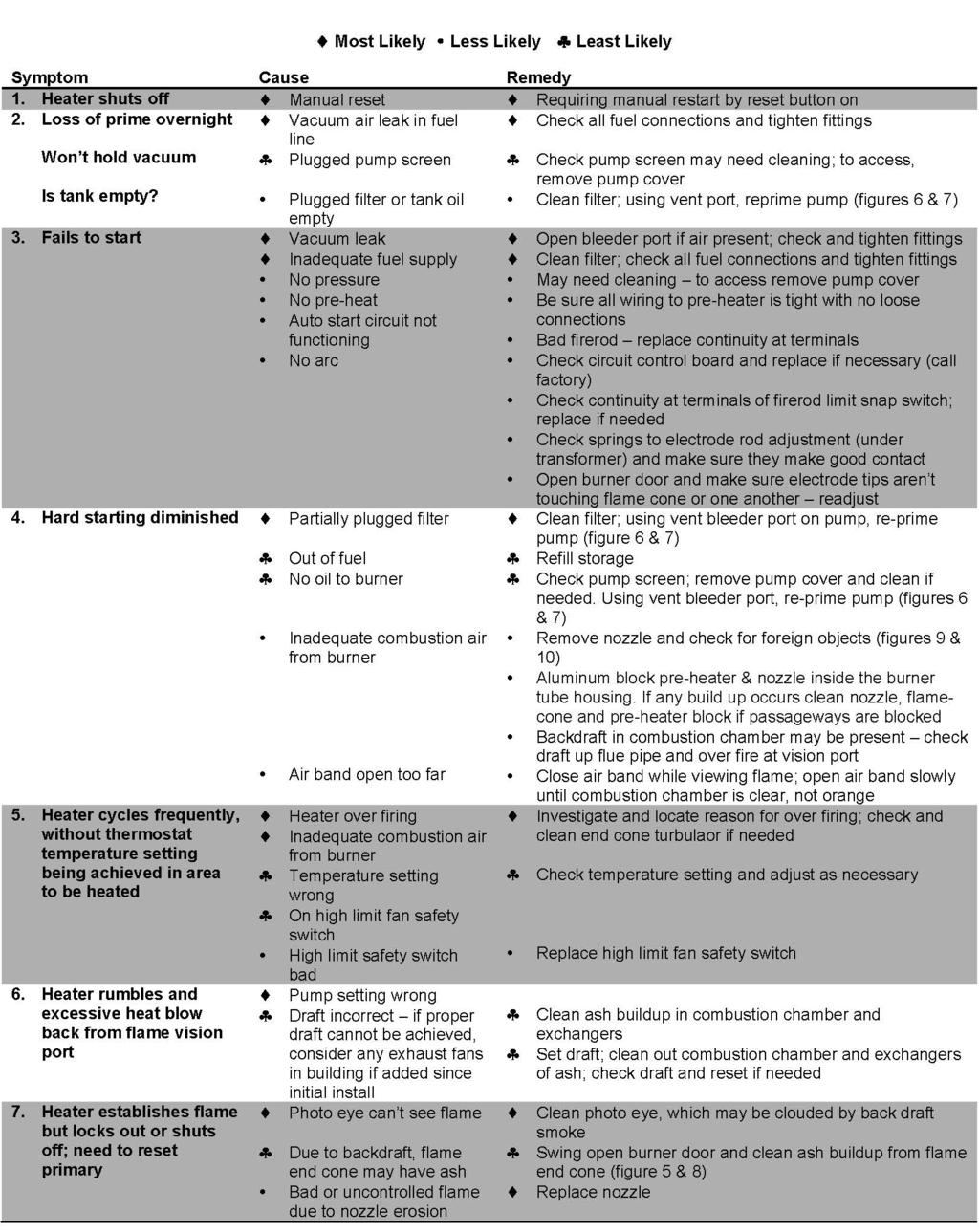
17 Troubleshooting Page 17

18 Troubleshooting Continued EH-75 Ten (10) Year Limited Warranty EconoHeat (manufacturer) warrants to the purchaser of Unit Heaters listed above will be free from defects in materials and workmanship for the durations specified below, which duration begins on the date of delivery to the customer. Customer is responsible for maintaining proof of date of delivery. If return is deemed necessary for warranty evaluation and determination of repair or replacement, unit heater is to be sent to the factory with freight prepaid. EconoHeat reserves the right to determine appropriate action for repair or replacement. No parts will be accepted by EconoHeat without RA# (return authorization number) clearly marked on outside of shipping package. Obtaining RA# requires model and serial numbers, description of part being replaced and nature of defect. Call factory to receive RA#. Warranty Covers: Combustion chamber and heat exchanger ten (10) years limited, full repair or replacement (parts only), first three (3) fullly covered / last seven (7) 50% coverage Oil heater block, one (1) years (parts only) Oil heater block controller PCB, three (3) years (parts only) All other components, one (1) year (parts only) Page 18
19 EH-75 Ten (10) Year Limited Warranty Cont. This warranty is void if: Warranty registration card is not returned within sixty (60) days of purchase Any part or component subject to abuse or altered from original manufactures specifications Installation not in accordance with instructions Has not been properly maintained, operated or has been misused Wiring not in accordance with diagram furnished with unit heater Unit heater is operated in the presence of chlorinated vapors Air through unit heater is not in accordance with rating plate and specifications Target plate or clean out door warped/discolored from excessive heat Warranty is limited to the original purchaser and is non-transferable. The above warranty is in lieu of all other warranties expressed or implied. EconoHeat does not authorize any person or representative to make or assume any other obligation or liability that is not in accordance with above warranty. EconoHeat is not responsible for any labor and/ or shipping cost, unless prior authorization in writing has been obtained. NOTE: Combustion Chamber Warranty is specific to material and workmanship. Workmanship means EconoHeat warranties the welds are good and will hold. Material means they will not corrode through due to sulfur in the ash that accumulates during operation. Warranty does not apply to units that experience overheating stress cracks. These are not incurred because the materials are inadequate for the application nor are they results of a weld breaking lose because of bad penetration, which is easily recognized by the metal left beneath the weld. These cracks occur as a direct result of (1)improper draft, either by inadequate initial installation and setup, which requires (a) establishing a proper draft during installation (b) back draft has occurred due to ash buildup, backing up hot gas passageways in either the exchangers, the stack, or both. (2) Over firing by setting oil supply pressure too high (see manual for proper setting) these are all cases of thermal overload. *Under normal use only. If misuse or abuse is deemed apparent after inspection, warranty is void. Page 19
20 Warranty Card Please fill out, tear off and return to manufacturer within sixty (60) days of purchase, or warranty will not be valid. Please print or type. Date of Purchase: Serial #: Model #: Customer (Company) Name: Address: City: State: Zip Code: Dealer: Address: City: State: Zip Code: Installed By: Page 20
Waste Oil Fired Heater. Installation, operation and service instructions OWH v Manual
 Waste Oil Fired Heater Installation, operation and service instructions OWH-75 120v Manual EconoHeat 5714 E. First Avenue Spokane Valley, WA 99212 800.255.1363 www.econoheat.com Rev 01/2017 Table of Contents
Waste Oil Fired Heater. Installation, operation and service instructions OWH v Manual
 Waste Oil Fired Heater Installation, operation and service instructions OWH-350 120v Manual EconoHeat 5714 E. First Avenue Spokane Valley, WA 99212 800.255.1363 www.econoheat.com Rev 01/2017 Table of Contents
WASTE OIL FIRED HEATERS
 By WASTE OIL FIRED HEATERS Installation, Operation, And Service Instructions Manual 120v MODEL OWH-150 150,000 BTU MODEL OWH-250 250,000 BTU MODEL OWH-350 350,000 BTU MODEL OWH-500 500,000 BTU Thank you
WASTE OIL FIRED MOBILE RADIANT HEATER Operation and Service Instructions. Manual MODEL OWR-150
 By WASTE OIL FIRED MOBILE RADIANT HEATER Operation and Service Instructions Manual MODEL OWR-150 Thank you and congratulations on your purchase of an Omni Waste Oil Fired Mobile Radiant Heater. You have
INTRODUCTION THIS MANUAL INCLUDES IMPORTANT SAFETY INFORMATION
 INSTALLATION AND OPERATING INSTRUCTIONS FOR THE HARDY Fuel Oil Furnace Models D-140 & D-350 HARDY MANUFACTURING COMPANY, INC. 12345 ROAD 505 PHILADELPHIA, MS 39350 PHONE: (601) 656-5866 FAX: (601) 656-4559
Waste Oil Fired Boiler. Installation, operation and service instructions OWB-25, OWB-35, OWB v Manual
 Waste Oil Fired Boiler Installation, operation and service instructions OWB-25, OWB-35, OWB-50 120v Manual EconoHeat 5714 E. First Avenue Spokane Valley, WA 99212 800.255.1363 www.econoheat.com Rev 09/2015
CELDEK Evaporative Cooler Module Installation, Operation, and Maintenance Manual. CELDEK Evaporative Cooler
 CELDEK Evaporative Cooler Module Installation, Operation, and Maintenance Manual CELDEK Evaporative Cooler RECEIVING AND INSPECTION Upon receiving unit, check for any interior and exterior damage, and
Standard and CELDEK Evaporative Cooler Modules Installation, Operation, and Maintenance Manual
 Standard and CELDEK Evaporative Cooler Modules Installation, Operation, and Maintenance Manual Standard Evaporative Cooler CELDEK Evaporative Cooler RECEIVING AND INSPECTION Upon receiving unit, check
OWNER S MANUAL FOR AIR ADMIRAL VACUUM/PRESSURE STATION MODELS:
 OWNER S MANUAL FOR AIR ADMIRAL VACUUM/PRESSURE STATION MODELS: 79202-00 79202-05 79202-30 79202-35 Approval Agency s Model 79202-00 & 79202-05 Model 79202-30 & 79202-35 Not recommended for pumping acid,
ELITE SERIES Lo-Boy. AFUE - 83% Heating Input - 101,000 to 151,000 Btuh Nominal Add-on Cooling to 5 Ton. OIL FURNACES El0183b
 PRODUCT SPECIFICATIONS OIL FURNACES El083b ELITE SERIES Lo-Boy Bulletin No. 20629 February 209 Supersedes July 202 MODEL NUMBER IDENTIFICATION el O 83 bf 0/4 p 60 AFUE - 83% Heating Input - 0,000 to 5,000
Corn Flame Energy Corn Stove Model 3000
 Corn Flame Energy Corn Stove Model 3000 Installation and Operation Guide Read thoroughly before starting installation Save this manual for future reference SAFETY NOTICE If this stove is not properly installed,
Standard and CELDEK Evaporative Cooler Modules Installation, Operation, and Maintenance Manual
 Standard and CELDEK Evaporative Cooler Modules Installation, Operation, and Maintenance Manual Standard Evaporative Cooler CELDEK Evaporative Cooler RECEIVING AND INSPECTION Upon receiving unit, check
Burner Comparisons. Typical Competitor s Burner
 Burner Comparisons INOV8 s Typical Competitor s Burner Automatic nozzle cleanout Yes No Available BTUs rated as input 100,000 to 1,000,000 76,500 to 500,000 Burner Motor - hp 1/5 1/7 Combustion safety
DOMESTIC WATER HEATER OIL FIRED
 DOMESTIC WATER HEATER OIL FIRED Models : CMO32-II CMO32-II-R CMO50-II CMO32-II & CMO32-II-R INSTALLER / SERVICE TECHNICIAN: USE THE INFORMATION IN THIS MANUAL FOR THE INSTALLATION AND SERVICING OF THE
Installation & Service Instructions for Jackson & Church Flexaire Packaged Furnaces SDF-125 thru SDF-400 Gas Firing
 Installation & Service Instructions for Jackson & Church Flexaire Packaged Furnaces SDF-125 thru SDF-400 Gas Firing Important: To protect the unit and avoid damage to the heat exchanger, the blower speed
Packaged Gas/Electric Units. Owner s Guide to Operating and Maintaining Your Gas/Electric Unit
 Packaged Gas/Electric Units Owner s Guide to Operating and Maintaining Your Gas/Electric Unit ELECTRICAL SHOCK HAZARD. FIRE OR EXPLOSION HAZARD Disconnect power at fuse box or service panel before performing
CMO32 CMO50 DOMESTIC WATER HEATER OIL-FIRED. Models: CMO32 CMO50
 DOMESTIC WATER HEATER OIL-FIRED Models: CMO32 CMO50 DNS-1102 Rev. A DNS-0413 Rev. A CMO32 CMO50 INSTALLER / SERVICE TECHNICIAN: USE THE INFORMATION IN THIS MANUAL FOR THE INSTALLATION AND SERVICING OF
CINCINNATI, OH USA
 INSTRUCTION MANUAL Part No. 89731 Revised October 1997 CINCINNATI, OH 45241-4807 USA GAS SAFETY PRECAUTIONS Instructions on what to do when a user smells gas can be obtained from the local gas supplier.
Model RGAC/SGAC Self Contained Cooling/Gas Heat MODELS RGAC & SGAC - R22 USER'S INFORMATION, MAINTENANCE AND SERVICE MANUAL
 Model RGAC/SGAC Self Contained Cooling/Gas Heat Supersedes: 145.24-O1 (708) Units Form 145.24-O1 (908) MODELS RGAC & SGAC - R22 USER'S INFORMATION, MAINTENANCE AND SERVICE MANUAL CATEGORY III GAS HEATING/ELECTRIC
120 VAC SYSTEM CONTROL KIT Model: CK-63
 120 VAC SYSTEM CONTROL KIT Model: CK-63 Designed for use on SWG Series Power Vent Hoods for controlling oil fired heating appliances with 120 VAC controls. The CK-63 control has the ability to operate
10.1 Troubleshooting Condition Table
 10.1 Troubleshooting Condition Table Behavior 01. The furnace does not operate when you set the wall thermostat to a high temperature. Component 1. Wall T-Stat (See Section 10.3) 2. Blower/Fan Limit (See
- 12 VDC. HHE M - 12 VDC.
 R OWNER S MANUAL Model Number HHE-200-09E - 12 VDC. HHE-500-09M - 12 VDC. OWNER S INFORMATION Owner s Name: Address: City: State: Zip Code: CUT HERE AND MAIL IN Telephone: E-mail Address: Motorhome Model:
VF/VG700 Jumbo. Construction Heater. Installation and Maintenance Manual
 342 N. Co. Rd. 400 East Valparaiso, IN 46383 888-432-8924 Fax 219-462-7985 www.heatwagon.com Installation and Maintenance Manual Please retain this manual for future reference. VF/VG700 Jumbo Construction
US Filtermaxx. 200,000 BTU Waste Oil Burner
 US Filtermaxx 200,000 BTU Waste Oil Burner Assemble the Burner: Remove all the parts from the box. Locate the burner flange coupling and attach it to the front of the burner as seen in the photo below
FOR EASY, FAST INSTALLATION AND FOR RESULTS
 Page 1 INSTALLATION & OPERATING INSTRUCTIONS FOR FEDERAL FLOOR FURNACE OFB-100 AND OFB100L UNPACK SHIPMENT CAREFULLY AND INSPECT FOR DAMAGE. ALL GOODS ARE CAREFULLY MANUFACTURED, INSPECTED, CHECKED, AND
Model Universal Oil Primary Control
 Model 70200 Universal Oil Primary Control Installation and Operating Instructions For Use By Qualified Service Technicians Only Universal Replacement for Carlin, Beckett, Honeywell and ICM Controls On-Board
Cookshack, Inc. Model FEC100 Fast Eddy Oven. Version /1/10
 Cookshack, Inc. Model FEC100 Fast Eddy Oven Operator s Manual Please read this entire manual installation and use of this pellet fired smoker oven. Failure to follow these instructions could result in
AFUE up to 85.2% Heating Input 105,000 to 245,000 Btuh
 WATER HEATERS / BOILERS COWB3 Oil-Fired Hot Water Boiler PRODUCT SPECIFICATIONS Bulletin No. 0654 March 08 Supersedes September 05 AFUE up to 85.% Heating Input 05,000 to 45,000 Btuh MODEL NUMBER IDENTIFICATION
MODEL HS115-3, HS115-4 & HS115-5 WIRING DIAGRAM ADDENDUM
 TJERNLUND PRODUCTS, INC. 1601 Ninth Street White Bear Lake, MN 55110-6794 PHONE (800) 255-4208 (651) 426-2993 FAX (651) 426-9547 Visit our web site www.tjernlund.com MODEL HS115-3, HS115-4 & HS115-5 WIRING
B.C.S. Shop Heaters 26, 30 & 36 (36 shown)
") BIOMASS COMBUSTION SYSTEMS, INC. 67 MILLBROOK ST., SUITE 502 WORCESTER, MA 01606 508-798-5970 - FAX 508-798-5971 B.C.S. Shop Heaters 26, 30 & 36 (36 shown) INSTALLATION MANUAL HAND FIRED SYSTEMS 8-09 Biomass
BIOMASS COMBUSTION SYSTEMS, INC. 67 MILLBROOK ST., SUITE 502 WORCESTER, MA 01606 508-798-5970 - FAX 508-798-5971 B.C.S. Shop Heaters 26, 30 & 36 (36 shown) INSTALLATION MANUAL HAND FIRED SYSTEMS 8-09 Biomass
Sanitaire. Owner s Guide. 10 GALLON Box Extractor SC6088 Series IMPORTANT
 Sanitaire 10 GALLON Box Extractor SC6088 Series Part No. SC6088 Rev 2 (3/14) Owner s Guide IMPORTANT Do not return this product to the store. Call 1-800-800-8975* Monday - Friday 8:00 AM to 7:30 PM and
MODEL MSR & MSR-DC OIL BURNERS
 WAYNE COMBUSTION SYSTEMS 801 GLASGOW AVE. FORT WAYNE, IN 46803 MODEL MSR & MSR-DC OIL BURNERS Publication Date 8/14/2000 Revision C Manual 22019-003 ELECTRIC SHOCK HAZARD HIGH VOLTAGES ARE PRESENT IN THIS
Installation and Operating Instructions ISH ELECTRIC STEAM SUPERHEATER
 Installation and Operating Instructions ISH ELECTRIC STEAM SUPERHEATER 1 Installation and Operating Instructions ISH ELECTRIC STEAM SUPERHEATER FOR YOUR SAFETY This manual supplies information on the application,
Columbia Boiler Company
 EMG Series Boilers Available in Natural Gas & Propane Rev 12012 Columbia Boiler Company PO Box 1070 Pottstown, PA 19464 Tel (610) 473-8457 Fax (610) 367-6800 Website www.columbiaboiler.com Email cbcsales@ptd.net
MODEL HI-100i / HI-140i
 P/N # 5359 MANUFACTURED BY: 4109 CAPITAL CIRCLE JANESVILLE, WISCONSIN 53546 1-800-753-1601 FAX 1-608-757-7878 www.lanair.com INSTALLATION AND OPERATING INSTRUCTIONS MODEL HI-100i / HI-140i ALL INSTALLATIONS
HI Industrial Utility Heater HI Soleus Air International
 HI1-50-03 Industrial Utility Heater HI1-50-03 2010 Soleus Air International Thank you for choosing a Soleus Air Utility Heater. This owner s manual will provide you with valuable information necessary
Internet Version for Reference Only INDUCED DRAFT COMMERCIAL WATER HEATERS SUPPLEMENT INSTRUCTIONS TO PART #
 INDUCED DRAFT COMMERCIAL WATER HEATERS SUPPLEMENT INSTRUCTIONS TO PART #238-39387-00 THIS INSTRUCTION SUPPLEMENT IS ONLY INTENDED TO GIVE INSTALLATION INSTRUCTIONS AND INFORMATION RELATED TO THE INDUCED
INSTALLATION INSTRUCTIONS
 INSTALLATION INSTRUCTIONS Keep these instructions with the boiler at all times. BOYERTOWN FURNACE CO. PO Box 100 BOYERTOWN, PA 19512 1-610-369-1450 www.boyertownfurnace.com 5-25-12 2 Danger Warning Caution
Burn Easy Installation Instructions LP or Natural Gas Fired Units. Cremator Setup:
 Burn Easy Installation Instructions LP or Natural Gas Fired Units Cremator Setup: 1. Place cremator, outdoor on a solid base consisting of concrete or gravel. Keep this site free of all vegetation. Combustibles
OPERATOR S MANUAL SF-12 AND SF12A HI VOLUME WATER HEATER
 OPERATOR S MANUAL SF-12 AND SF12A HI VOLUME WATER HEATER MODELS SF12-A PICTURED Page 1 of 12 Table of Contents Safety Precautions Section 1. Section 2. Section 3. Section 4. Section 5. Section 6. Systems
INSTALLATION AND OPERATION INSTRUCTIONS
 Printed in U.S.A. INSTALLATION AND OPERATION INSTRUCTIONS RFPA21A CONSTRUCTION HEATER FLOOR MODEL SAVE FOR FUTURE REFERENCE Space-Ray Division, Gas Fired Products, Inc. P.O. Box 36485, Charlotte, NC 28236
24 VAC SYSTEM CONTROL KIT Model: CK-91F and CK-91FG
 24 VAC SYSTEM CONTROL KIT Model: CK-91F and CK-91FG Designed for use with the SWG Series Power Venter for controlling Natural Gas or L.P. Gas draft induced appliances with a 24 VAC Gas Valve and a 30-millivolt
USER S INFORMATION MANUAL
 USER S INFORMATION MANUAL HOT WATER HEATING BOILERS DOMESTIC WATER HEATERS 150,000-300,000 Btu/hr MODELS EB-EWU-02 IMPORTANT INSTALLER - AFFIX INSTALLATION MANUAL ADJACENT TO THE BOILER CONSUMER - RETAIN
USER MANUAL SOM SERIES MUL-T-POISE WARM AIR OIL FIRED FURNACE
 USER MANUAL SOM SERIES MUL-T-POISE WARM AIR OIL FIRED FURNACE Save These Instructions For Reference ALL SOM SERIES FURNACES ARE AIR CONDITIONING READY! NOTICE TO HOMEOWNER THIS FURNACE SHALL BE INSTALLED
SECTION AUXILIARY HEATER
 14-301.03/ 1 2010MR12 SECTION 14-301.03 GENERAL DESCRIPTION The Thermo 300 auxiliary heating system is used in conjunction with the vehicle s heating system, in order to heat the passenger compartment
Xaact Spot. Xaact Hot Spot
 Xaact Spot & Xaact Hot Spot INFORMATION & OPERATING INSTRUCTIONS READ AND UNDERSTAND THESE INSTRUCTIONS BEFORE OPERATING THE MACHINE 78-00012 Rev. 101211 1 CONTENTS: Machine Specifications............
Light oil burners. One stage operation
 Installation, use and maintenance instructions Light oil burners One stage operation CODE MODEL TYPE 3505 RDB CF 38 50 T3 350050 RDBR CF 6 50 TR 35050 RDBR CF 33 50 TR 35050 RDBR CF 38 50 T3R 350650 RDBR
TJERNLUND PRODUCTS, INC.
 TJERNLUND PRODUCTS, INC. 1601 Ninth Street White Bear Lake, MN 55110-6794 PHONE (800) 255-4208 (651) 426-2993 FAX (651) 426-9547 Visit our web site www.tjernlund.com PRESSURE SWITCH AND INSTALLATION WITH
ZG Shown READ ALL INSTRUCTIONS IN THIS MANUAL AND RETAIN FOR FUTURE REFERENCE WARNING
 See unit nameplate for manufacturer and address. 507258-04 7/2018 Supersedes 10/2017 ZG 036, 048, 060, 072, 074 (3, 4, 5 and 6 Tons) ZG 092, 102, 120, 150 (7-1/2, 8-1/2, 10 and 12 Tons) ROOFTOP UNITS ZG
SERVICE AND INSTALLATION MANUAL MODELS HDO(H) OIL FOR YOUR SAFETY
 OIL FOR YOUR SAFETY") Bousquet Technologies Inc. 2121, Nobel, Ste Julie, Quebec, Canada, J3E1Z9 SERVICE AND INSTALLATION MANUAL MODELS HDO(H) OIL Oil-Fired air heater for industrial and commercial use. FOR YOUR SAFETY Do not
Bousquet Technologies Inc. 2121, Nobel, Ste Julie, Quebec, Canada, J3E1Z9 SERVICE AND INSTALLATION MANUAL MODELS HDO(H) OIL Oil-Fired air heater for industrial and commercial use. FOR YOUR SAFETY Do not
4000IS PROFESSIONAL IRONING SYSTEM INSTRUCTION MANUAL
 4000IS PROFESSIONAL IRONING SYSTEM INSTRUCTION MANUAL THE 4000IS PROFESSIONAL IRONING SYSTEM INSTRUCTION MANUAL ENGLISH 01 RELIABLE. RIGHT THERE WITH YOU. At Reliable, we do what we love, and take pride
OPERATING INSTRUCTIONS SMO112 WARM AIR OIL FIRED FURNACE
 OPERATING INSTRUCTIONS SMO112 WARM AIR OIL FIRED FURNACE Save These Instructions For Reference SMO 112 FURNACES ARE AIR CONDITIONING READY! NOTICE TO HOMEOWNER THIS FURNACE SHALL BE INSTALLED BY A CERTIFIED
REZNOR USED-OIL-FIRED HEATERS AND BOILERS. Installation / Operation / Maintenance Manual and Reference Guide. Model RAB Sizes 350 and 500
 Form I-RAB (Version A) Obsoletes Form I-RAB REZR USED-OIL-FIRED HEATERS AND BOILERS Installation / Operation / Maintenance Manual and Reference Guide Model RAB Sizes 350 and 500 CUSTOMER AGENCY PROCESS
Interrupted Ignition Series Oil Primary Control
 Interrupted Ignition Series Oil Primary Control Application Guide & Installation Instruction for ICM1511*, ICM1512*, ICM151*, ICM1514* For more information on our complete range of American-made products
FLCH4R Garage and Utility Electric Heater
 FLCH4R Garage and Utility Electric Heater Installation, Operation & Maintenance Instructions Model No. Volts Amps Watts BTU/HR Phase High Low High Low High Low Min Fuse Size* FLCH4R 208 17.3 8.66 3600
Model 601CRD Oil Burner
 Model 601CRD Oil Burner Installation and Operating Instructions For Use By Qualified Service Technicians Only CRD burners feature a combustion head incorporating a new design concept which provides a means
USER MANUAL SLO / SFLO115 SERIES OIL FIRED WARM AIR FURNACES
 USER MANUAL SLO / SFLO115 SERIES OIL FIRED WARM AIR FURNACES Save These Instructions For Reference ALL SUMMERAIRE SLO115 / SFLO115 MODELS ARE AIR CONDITIONING READY! NOTICE TO HOMEOWNER THIS FURNACE SHALL
INFRARED RADIANT HEATER RSCA SERIES CERAMIC HEATERS NATURAL GAS PROPANE GAS DATE: PROJECT: ARCHITECT/ENGINEER: CONTRACTOR: SUBMITTED BY:
 INFRARED RADIANT HEATER RSCA SERIES CERAMIC HEATERS NATURAL GAS (CHECK ONE) PROPANE GAS PROJECT: ARCHITECT/ENGINEER: NAME: ADDRESS: NAME: ADDRESS: DATE: CONTRACTOR: SUBMITTED BY: NAME: ADDRESS: EQUIPMENT
RecoverX-CAR Contaminated Automotive Refrigerant Recovery System Operation and Maintenance Manual
 RecoverX-CAR Contaminated Automotive Refrigerant Recovery System Operation and Maintenance Manual (English) Table of Contents Page General Safety Instructions...2 System Overview...3 RecoverX-CAR Operation
USER S INFORMATION MANUAL
 USER S INFORMATION MANUAL UPFLOW/HORIZONTAL & DOWNFLOW TWO STAGE INDUCED DRAFT GAS FURNACES Recognize this symbol as an indication of Important Safety Information If the information in this manual is not
DIESEL/PARAFFIN HEATERS
 DIESEL/PARAFFIN HEATERS MODEL NO: XR80, XR110, XR160, XR210 PART NO: 6931004, 6931006, 6931008, 6931012 OPERATION & MAINTENANCE INSTRUCTIONS LS0814 INTRODUCTION Thank you for purchasing this CLARKE product.
INSTALLATION AND OPERATING MANUAL
 dickinson since 1932 MODEL 00-NEW-P12000 INSTALLATION AND OPERATING MANUAL Manufactured by: Dickinson Marine (1997) Ltd, 407-204 Cayer Street, Coquitlam, British Columbia, Canada V3K 5B1 www.ahoycaptain.com
DHI-300 DUCTABLE WASTE OIL HEATER
 DHI-300 DUCTABLE WASTE OIL HEATER Installation and Operating Instructions Listed MH 14518 (N) Lanair Waste Oil Heaters & Boilers 4109 Capital Circle Janesville, Wisconsin 53546 608-752-1601 www.lanair.com
Direct Vent System Required
 CB-200A Cottage Base Installation Instructions IMPORTANT: Read all instructions carefully before beginning the installation. This base must be installed by a qualified installing agency and in accordance
KGA092 SHOWN READ ALL INSTRUCTIONS IN THIS MANUAL AND RETAIN FOR FUTURE REFERENCE WARNING
 See unit nameplate for manufacturer and address. 506380 01 11/2009 KGA024, 030, 036, 048, 060, 072 (2, 2 1/2, 3, 4, 5, and 6 Tons) KGA092, 102, 120, 150 (7 1/2, 8-1/2, 10, and 12 Tons) KGA180, 210, 240,
PARAFFIN/DIESEL HEATER
 PARAFFIN/DIESEL HEATER MODEL NO: XR60 PART NO: 6931002 OPERATION & MAINTENANCE INSTRUCTIONS LS0813 INTRODUCTION Thank you for purchasing this CLARKE product. Before attempting to use this product, please
WILKERSON MODELS DE3, DE4 AND DE5 COMPACT HEATLESS AIR DRYERS
 INSTRUCTION MANUAL FOR WILKERSON MODELS DE3, DE4 AND DE5 COMPACT HEATLESS AIR DRYERS DE3 - DE5 OPERATIONS GENERAL This instruction manual covers the installation, operation, maintenance and troubleshooting
Packaged Gas/Electric
 Packaged Gas/Electric Units Owner's Guide to Operating and Maintaining Your Gas/Electric Unit ELECTRICAL SHOCK HAZARD. FIRE OR EXPLOSION HAZARD Failure to follow this warning can result in Disconnect power
Operation and Maintenance Manual
 Warranty Information Ritchie Engineering guarantees YELLOW JACKET products to be free of defective material and workmanship which could affect the life of the product when used for the purpose for which
RecoverX Oil-Filled Hermetic Refrigerant Recovery System. Operation and Maintenance Manual
 RecoverX Oil-Filled Hermetic Refrigerant Recovery System Operation and Maintenance Manual Table of Contents Page General Safety Instructions 2-3 System Overview 3 Operating Guide 4 Restart Procedure 4
POWER VENTER. Model: PVE Series
 POWER VENTER Model: PVE Series CONTENTS Typical Venting System Components... System Operation... Power Venter Sizing... Installation Safety Instructions... Installation of Power Venter... Connecting Power
OPERATING INSTRUCTIONS MANUAL (Please retain for future reference) FVO-200 INDIRECT FIRED SPACE HEATERS
 FVO-200 INDIRECT FIRED SPACE HEATERS") OPERATING INSTRUCTIONS MANUAL (Please retain for future reference) For FVO-200 INDIRECT FIRED SPACE HEATERS CERTIFIED FOR USE IN CANADA AND U.S.A. As per CSA B140.8 Portable Oil Fired Heaters / CSA B140.02003
OPERATING INSTRUCTIONS MANUAL (Please retain for future reference) For FVO-200 INDIRECT FIRED SPACE HEATERS CERTIFIED FOR USE IN CANADA AND U.S.A. As per CSA B140.8 Portable Oil Fired Heaters / CSA B140.02003
User s Information Manual
 48AJ,AK,AW,AY020-060 Single-Package Rooftop Gas Heating Units with COMFORTLINK Controls and Scroll Compressors User s Information Manual NOTE TO INSTALLER This manual should be left with the equipment
TG-10 Wall Mount Installation and Operation Manual. High Output Ozone Generator
 TG-10 Wall Mount Installation and Operation Manual High Output Ozone Generator Ozone Solutions 451 Black Forest Road Hull, IA 51239 Phone: (712) 439-6889 Fax: (712) 439-6733 2 Table of Contents Safety
AHE S -12 VDC AHE S - 24 VDC
 Owner s Manual Model Numbers AHE-100-02S -12 VDC AHE-200-02S - 24 VDC OWNER S INFORMATION Owner s Name: Address: City: State: Zip Code: CUT HERE AND MAIL IN Telephone: Coach Model: Coach Date of Purchase:
Service Parts, Kits and Accessories
 The parts identification guides on the following pages have been designed to give a quick reference to component parts used on pilot ignition agricultural building heaters. The guides identify components
R Series B & T2 Model
 FRONT R Series B & T2 Model Fan Forced Wall Heaters 4-1/4 (108mm) NOTE: Knockouts in top same dimensions 3-1/4 3-1/4 (108mm) (108mm) as bottom 16-7/8 (429mm) 13-7/8 (352mm) BOTTOM 13-7/8 (352mm) 7-3/4
Fire Bowls and Fire Bowl Inserts (Automated Operation) Operating and Maintenance Instructions
 Operating and Maintenance Instructions") Table of Contents Section 1: Gas and Electric Requirements... 1 Section 2: Installation... 2 Section 3: Burner Setup and Adjustment... 8 Burner Adjustment... 9 Section 4: Maintenance... 10 Section 5: Operation...
Table of Contents Section 1: Gas and Electric Requirements... 1 Section 2: Installation... 2 Section 3: Burner Setup and Adjustment... 8 Burner Adjustment... 9 Section 4: Maintenance... 10 Section 5: Operation...
IMPORTANT SAFETY INFORMATION
 OPERATION INSTALLATION PARTS MANUAL www.fostoriaindustries.com Made in U.S.A. ELECTRIC PORTABLE HEATER FES-1024-1CA 08860010 YES-1024-1CA 08861510 FES-1520-3A 08860110 YES-1520-3A 08860810 FES-1524-1A
SERVICE FACTS WARNING M801-SF-1C. Gas Furnaces Upflow & Downflow Induced Draft 1 Stage Heat Models: DISCONNECT POWER BEFORE SERVICING M801P040AU24AA
 SERVICE FACTS Gas Furnaces Upflow & Downflow Induced Draft Stage Heat Models: M80P00AU2AA M80P060AU2AA M80P060AU36AA M80P080BU36AA M80P080BU8AA M80P00BU36AA M80P00CU8AA M80P00CU60AA M80PDU60AA M80P0DU60AA
Circulating Oil Temperature Control System
 Installation & Operation Manual Circulating Oil Temperature Control System i PQ451 161-123417-037 February 2019 Table of Contents Contents Page Number Section 1 Getting Started... 1 Section 2 Installation...
Dust Collector. Sizes DC1 and DC2 U S E R G U I D E UGC
 U S E R G U I D E UGC033-0194 www.conairgroup.com Dust Collector Sizes DC1 and DC2 Corporate Office: 724.584.5500 l Instant Access 24/7 (Parts and Service): 800.458.1960 l Parts and Service: 814.437.6861
Fully-automatic Gas tankless Water Heater USER'S MANUAL FOR MODEL EZ-101 ISO9001 certified
 Fully-automatic Gas tankless Water Heater USER'S MANUAL FOR MODEL EZ-101 ISO9001 certified Thank you for purchasing our fully-automatic gas-fired tankless water heater. Please completely read this Manual
DAVE LENNOX SIGNATURE COLLECTION Lo-Boy - Variable Speed Blower
 PRODUCT SPECIFICATIONS OIL FURNACES sl085bv DAVE LENNOX SIGNATURE COLLECTION Lo-Boy - Variable Speed Blower Bulletin No. 0677 August 05 Supersedes September 04 AFUE - Up to 87% Heating Input - 79,000 to
OIL-FIRED CENTRAL FURNACE
 OIL-FIRED CENTRAL FURNACE Installation, Operation, and Service Manual With Users Information Section Models: CSHB60-90XE CSHB60-90XP c WARNING: Do NOT store or use gasoline or other flammable vapors and
TGA/KGA024, 030, 036, 048, 060, 072, 090 (2, 2 1/2, 3, 4, 5, 6, and 7 1/2 TONS)
") See unit nameplate for manufacturer and address. 506003 01 5/2009 Supersedes 1/2008 TGA/KGA024, 030, 036, 048, 060, 072, 090 (2, 2 1/2, 3, 4, 5, 6, and 7 1/2 TONS) TGA090, 102, 120, 150, TGA120 SHOWN (7
See unit nameplate for manufacturer and address. 506003 01 5/2009 Supersedes 1/2008 TGA/KGA024, 030, 036, 048, 060, 072, 090 (2, 2 1/2, 3, 4, 5, 6, and 7 1/2 TONS) TGA090, 102, 120, 150, TGA120 SHOWN (7
Indiana WX Oil Furnace Inspection Guide
 Indiana WX Oil Furnace Inspection Guide Client: Job # : Address: Phone: Client Interview: Oil Dealer: Date of last service: Comments/Billing information: Standard Inspection / Clean and Tune Follow-up:
IMPORTANT INSTRUCTIONS
 IMPORTANT INSTRUCTIONS W Fan Force Electric Space Heater DANGER ELECTRIC SHOCK OR FIRE HAZARD Figure 1 Covers all W Series models WARNING Read Carefully - These instructions are written in an effort to
Operating Instructions & Parts Manual. Silent Low-Profile Ceiling Fans. Models 3DPE2A, 3DPE3A, 1UBH6B, 1UBH7B, 1UBH8A, 5AE68B, 5AE69A
 Operating Instructions & Parts Manual EN Silent Low-Profile Ceiling Fans Models 3DPE2A, 3DPE3A, 1UBH6B, 1UBH7B, 1UBH8A, 5AE68B, 5AE69A 465933 PLEASE READ AND SAVE THESE INSTRUCTIONS. READ CAREFULLY BEFORE
Quest Power Electric Heat EHS 31 Pro
 Quest DRY Power 150 Electric Heat EHS 31 Pro Read and Save These Instructions The Power Electric Heat EHS 31 Pro portable, heavy duty electric heater features a built-in 50-amp twist lock receptacle designed
SYSTEM CONTROL KIT READ THESE INSTRUCTIONS CAREFULLY AND COMPLETELY BEFORE PROCEEDING WITH THE INSTALLATION.
 SYSTEM CONTROL KIT Model: CK-20F and CK-20FG (NOTE: CK-20FG units are designed for the Flame Guard units built by American Water Heater. All other manufacturers use CK-20F) Designed for use with the SWG
PVE SERIES POWER VENTER SYSTEM MANUAL
 PVE SERIES POWER VENTER SYSTEM MANUAL Contents Page I. Typical Venting System Components 2 II. System Operation 3 III. Power Venter Sizing 3,4 IV. Installation Safety Instructions 5,6 V. Installation of
USER S INFORMATION MANUAL
 USER S INFORMATION MANUAL UPFLOW & DOWNFLOW/HORIZONTAL CONDENSING GAS FURNACES SAFETY Recognize this symbol as an indication of Important Safety Information If not installed, operated and maintained in
INSTALLATION AND OPERATION MANUAL FOR 2 STAGE RIELLO BURNER ADDENDUM TO ( Mo 437 manual )
") INSTALLATION AND OPERATION MANUAL FOR 2 STAGE RIELLO BURNER ADDENDUM TO ( Mo 437 manual ) FOR USE WITH MODEL: OH6FX072DV4 PLEASE READ THESE INSTRUCTIONS PRIOR TO INSTALLATION, INITIAL FIRING, AND BEFORE
INSTALLATION AND OPERATION MANUAL FOR 2 STAGE RIELLO BURNER ADDENDUM TO ( Mo 437 manual ) FOR USE WITH MODEL: OH6FX072DV4 PLEASE READ THESE INSTRUCTIONS PRIOR TO INSTALLATION, INITIAL FIRING, AND BEFORE
KG 092 SHOWN READ ALL INSTRUCTIONS IN THIS MANUAL AND RETAIN FOR FUTURE REFERENCE WARNING
 See unit nameplate for manufacturer and address. 507350-03 3/2016 Supersedes 9/2015 KG 024, 030, 036, 048, 060, 072, 074, 090 (2, 2-1/2, 3, 4, 5, 6 and 7-1/2 Tons) KG 092, 102, 120, 150 (7-1/2, 8 1/2,
Single stage operation oil burner
 Installation & Operating Manual Single stage operation oil burner WARNING NON-RETROFIT APPLICATIONS If this burner is being installed in a packaged unit (ie. burner comes with a boiler or furnace), follow
HOMEOWNER'S GUIDE FOR YOUR CONTEMPO FIREPLACE TABLE OF CONTENTS
 10031 Southern SE Albuquerque NM 87123 505.291.0500 fax 505.291.9317 HOMEOWNER'S GUIDE FOR YOUR CONTEMPO FIREPLACE Before building your first fire, read this warranty and operation manual carefully. By
READ AND UNDERSTAND THESE INSTRUCTIONS BEFORE OPERATING THE MACHINE
 XAACT Xtract 200 INFORMATION & OPERATING INSTRUCTIONS READ AND UNDERSTAND THESE INSTRUCTIONS BEFORE OPERATING THE MACHINE 78-00018 Rev B 032912 1 CONTENTS: Machine Specifications............ 2 Record Important
Model No. GB-PAC-08E4. 8,000 BTU Portable Air Conditioner Operating Instructions
 Model No. GB-PAC-08E4 8,000 BTU Portable Air Conditioner Operating Instructions Thank you for choosing a Soleus Air Powered by Gree Portable Air Conditioner. This owner s manual will provide you with valuable
WMHP Series R410a Heat Pump INSTALLATION INSTRUCTIONS
 WMHP Series R410a Heat Pump INSTALLATION INSTRUCTIONS **WARNING TO INSTALLER, SERVICE PERSONNEL AND OWNER** Altering the product or replacing parts with non authorized factory parts voids all warranty