CS-MVG103KE CU-MVG153KE
|
|
|
- Chloe Lambert
- 6 years ago
- Views:
Transcription


1 Order number RAC9908C Room Air Conditioners CS-MVG0KE CU-MVGKE 999 Matsushita Electric Industrial Co., Ltd. All rights reserved. Unauthorized copying and distribution is a violation of law.
2 CS-MVG0KE / CU-MVGKE CONTENTS Page Page Features Functions.. REMOTE CONTROL.. INDOOR UNIT.. OUTDOOR UNIT 6 Product Specifications 7 Dimensions 9.. CS-MVG0KE (INDOOR UNIT) 9.. CU-MVGKE (OUTDOOR UNIT) 0 Refrigeration Cycle Diagram 6 Block Diagram 7 Wiring Diagram 7.. CS-MVG0KE ( INDOOR UNIT ) 7.. CU-MVGKE ( OUTDOOR UNIT ) 8 Operation Details (FUNCTIONS) 8.. SIMULTANEOUS OPERATION CONTROL 8.. TEMPERATURE SHIFT COMPRESSOR OPERATING FREQUENCY OPERATION COOLING OPERATION SOFT DRY OPERATION HEATING OPERATION 8.7. FAN OPERATION 8.8. AUTOMATIC OPERATION 8.9. INDOOR FAN SPEED CONTROL OUTDOOR FAN CONTROL AIRFLOW DIRECTION QUIET OPERATION 8.. POWERFUL MODE OPERATION 8.. SLEEP MODE OPERATION 8.. DELAY ON TIMER CONTROL 8.6. AUTO RESTART CONTROL 8.7. POWER MONITOR DISPLAY 8.8. REMOTE CONTROL SIGNAL RECEIVING SOUND ON/OFF 9 Operation Details (PROTECTION) 9.. PROTECTION CONTROL FOR ALL OPERATIONS 9.. PROTECTION CONTROL FOR COOLING & SOFT DRY PROTECTION CONTROL FOR HEATING OPERATION 0 0 Installation And Servicing Air Conditioner Using R0A 0.. OUTLINE 0.. TOOLS FOR INSTALLING/SERVICING REFRIGERANT PIPING 0.. REFRIGERANT PIPING WORK INSTALLATION, TRANSFERRING, SERVICING 8 Installation Information.. ATTACHED ACCESSORIES.. SELECT THE BEST LOCATION.. INDOOR/OUTDOOR UNIT INSTALLATION DIAGRAM.. CONNECTION PIPES FOR AIR CONDITIONER UNITS WITH R0A.. NOTE Servicing Information 6.. TROUBLESHOOTING 6.. SELF DIAGNOSIS DISPLAY 8.. REMOTE CONTROL 60.. DISASSEMBLY OF PARTS 6 Technical Data 69.. OPERATION CHARACTERISTICS 69 Electronic Circuit Diagram 7.. HOW TO USE ELECTRONIC CIRCUIT DIAGRAM 7.. TIMER TABLE 7.. INDOOR UNIT 7.. OUTDOOR UNIT 7.. REMOTE CONTROLLER 76 Printed Circuit Board 77.. INDOOR UNIT 77.. OUTDOOR UNIT / MAIN PCB 79.. OUTDOOR UNIT / TRANSISTOR MODULE 8 6 Exploded View & Replacement Parts List CS-MVG0KE CU-MVGKE 8 7 Electronic Parts List 86 Features Product Powerful Mode for quick cool/heat Compressor operating frequency control to maintain desired room temperature Automatic Restart after power failure Washable front panel Power Monitor Display Serviceability Self diagnosis Test Run at both Cooling and Heating rated frequency Quality Improvement High power supply voltage protection Low power supply voltage protection Gas leakage detection
3 CS-MVG0KE / CU-MVGKE Functions.. REMOTE CONTROL
4 CS-MVG0KE / CU-MVGKE.. INDOOR UNIT
5 CS-MVG0KE / CU-MVGKE
6 CS-MVG0KE / CU-MVGKE.. OUTDOOR UNIT 6
7 CS-MVG0KE / CU-MVGKE Product Specifications Cooling Capacity Heating Capacity kw Btu/h Moisture Removal /h Pint/h Power Source Airflow Method Unit CS-MVG0KE CU-MVGKE ( unit) ( units) kw.8(0.7.).(0..) x Btu/h 9,00(,00,900) 7,60(,00 7,80) x Phase V Cycle ( unit) ( units).0(0.7.).6(0..0) x,600(,00,700) 8,80(,00 0,00) x ( unit) ( units).6... Single 0 0 Air Volume Indoor Air(Lo) m / min(cfm) Cooling ; 7.0(7) - Heating ; 7.() Indoor Air(Me) m / min(cfm) Cooling ; 7.6(68) - Heating ; 7.8(7) Indoor Air(Hi) m / min(cfm) Cooling ; 8.(9) - Heating ; 8.(00) Outdoor Air m / min(cfm) - Hi; 0.0(00) Noise Level db(a) Cooling ; High 9,Low 7 heating ; High 9,Low 7 Cooling ; 6 Heating ; 7 Electrical Input ( unit) ( units) Data kw Cooling ; 770(0,00),0(,80) Heating ;,0(,900),80(0,800) Running Current ( unit) ( units) A Cooling ;.70 ( max.0 ) 6.0 ( max 6.70 ) Heating ; 6. ( max 9.90 ) 6. ( max 9.90 ) COP ( unit) ( units) Cooling ;.6. Heating ;.0.06 Starting Current A 6.0 Piping Connection Port (Flare piping) inch inch G ; Half Union /8 L ; Half Union / G ; -Way valve /8 L ; -Way valve / Pipe Size (Flare piping) inch inch G(gas side) ; /8 L(liquid side) ; / G(gas side) ; /8 L(liquid side) ; / Drain Inner diameter mm - Hose Length m Power Cord length Number of core-wire Dimensions Height inch(mm) 0 - /(79) - /(0) Width inch(mm) - /(799) 0 - /(780) Depth inch(mm) 7 - /(90) - /(89) Net Weight lb(kg) 0(9.0) 9() Compressor Type - Rotary ( cylinder) Motor Type - Brushless(-poles) Rated Output W -,00 Air Circulation Type Cross-flow Fan Propeller Fan Material AS+Glass Fiber 0 AES+Giass Fiber Motor Type Transiator(-poles) Induction(6-poles) Input W - 0 rated Output W 0 Fan Low Cool(Heat) rpm 880(970) - Speed Medium Cool(Heat) rpm,00(,70) - High Cool(Heat) rpm,90(,0) 700 Heat Exchange description Evaporator Condenser Tube material Copper Copper Fine material Aluminium Aluminium Fine type Slit Fin Corrugated Fin Row/Stage (Plate fin configuration,forced draft) / / FPI 7 Size(W x H x L) mm 600 x x. 67 x 0 x 8. 6 x 0 x 8. 7
8 CS-MVG0KE / CU-MVGKE Unit CS-MVG0KE CU-MVGKE Refrigerant Control Device - Expansion Valve refrigeration Oil (c.c) - RB88A(90) Refrigerant(R0A) g(oz) - 0(.) Thermostat Electronic Control - Protection Device Electronic Control Air Filter Material style P.P Honeycomb Capacity Control Expansion valve Fan motor Capacitor µf,vac -.0µF,00VAC Specifications are subject to change without notice for further improvement. - 8
9 CS-MVG0KE / CU-MVGKE Dimensions.. CS-MVG0KE (INDOOR UNIT) 9
10 CS-MVG0KE / CU-MVGKE.. CU-MVGKE (OUTDOOR UNIT) 0
11 CS-MVG0KE / CU-MVGKE Refrigeration Cycle Diagram INDOOR A OUTDOOR STRAINER -WAY VALVE EXPANSION VALVE (A) DRYER STRAINER INTAKE TEMP. SENSOR PIPE TEMP. SENSOR EXPANSION VALVE (B) C HEAT EXCHANGER (EVAPORATOR) PIPE TEMP. SENSOR PIPE TEMP. SENSOR OUTDOOR AIR TEMP SENSOR -WAY VALVE PIPE TEMP. SENSOR INDOOR B HEAT EXCHANGER (CONDENSER) STRAINER -WAY VALVE INTAKE TEMP. SENSOR PIPE TEMP. SENSOR PIPE TEMP. SENSOR -WAY VALVE -WAY VALVE HEAT EXCHANGER (EVAPORATOR) SUCTION TEMP. SENSOR DISCHARGE TEMP SENSOR COMPRESSOR TEMP SENSOR -WAY VALVE COMPRESSOR C ; CAPILLARY TUBE COOLING HEATING
12 6 Block Diagram INDOOR UNIT A OUITDOOR POWER SUPPLY SINGLE PHASE 0V 0Hz OUTDOOR UNIT CS-MVG0KE / CU-MVGKE WIRELESS REMOTE CONTROL TRANSMITTER FUSE (.A) FUSE (0A) C.T. RY-AC PTC RY-PWR RECEIVER P.C.B. C RY-HOT RY-CV RY-L INCIDATOR P.C.B. FAN MOTOR FM 9C C ELECTRONIC CONTROLLER NOISE FILLTER ELECTRONIC CONTROLLER -WAY VALVE -WAY VALVE FAN MOTOR FM DIODE NOISE FILLTER COMPRESSOR LOUVER MOTOR C TERNINAL THERMAL FUSE 0 REACTOR C EXP.VALVE(A) C EXP.VALVE(B) INDOOR UNIT B SAME AS UNIT A Indicates the electronic control unit. "C" Indicates the number of core wires. (Example:C= core wires).
13 CS-MVG0KE / CU-MVGKE 7 Wiring Diagram 7.. CS-MVG0KE ( INDOOR UNIT ) PUMP DOWN SW. ( TEST RUN ) AUTO SW. ELECTRONIC CONTROL L ER FUSE T. A L 0V ZNR CN - MTR ( G ) RBY MOTOR W IREL ESS REMOTE CONTROL EL ECTRONI C CONTROLL ER ( RECEI VER) CN- RCV( W) 6 6 CN -PWR ( B ) TERMINAL COMPL ETE CN- STM (W ) P Y O R BR MOTOR LOUVER CN - DI SP (W) CN - RCV ( W ) CN - TH (W ) 6 W W W SENSOR (PIPE TEMP.) SENSOR (AIR TEMP.) SENSOR ( PI PE TEMP. ) WWWW W W W WW Y/G TERMINAL T O OUT DOOR UNIT THERMAL FUSE 0 C ( A) CN- DISP (W ) DISPLAY, SELF- DIAGNOSIS POWER MONITOR DISPL AY REMARKS B: BLUE BR : BROWN W: WHITE G:GREEN P: PINK Y: YELLOW O: ORANGE BL: BLACK R : RED Y/G: YELLOW/GREEN
14 CS-MVG0KE / CU-MVGKE 7.. CU-MVGKE ( OUTDOOR UNIT ) 0V/0Hz SINGLE PHASE TERMINAL BL FUSE WH 0V/ 0A BL G G TO I NDOOR UNIT TERMINAL A TO INDOOR UNIT B TERMINAL BL BL B BL OR GR REMARKS B: BLUE GR: GRAY BL: BLACK OR: ORANGE BR: BROWN P: PINK G: GREEN V: VIOLET R: RED WH: WHITE Y: YELLOW R WH NOISE FILTER AC (BLUE) CN - ROOM B (GREEN) FUSE T. 0A L0V CN -ROOM A (BLUE) + AC (BLACK) 0 BR WH WH GR AC (GRAY) FUSE T. A L0V B Y CAPACI TOR - + OR R R U 0V 70 F R BL B 7V F + TRADE MARK THE PRENTHESIZED LETTER IS INDICATED ON TERM I NAL COVER. COMP. TERMINAL N 0V 70 F P R B BL WH CN - V (BLUE) B P CN - L CN- PW M (WHITE) (WHITE) CN - W (YELLOW) Y V GR OR BR AC (WHITE) CR 0 CN- HOT REACTOR BR RY- AC (YEL L OW) P L RY- HOT BL BL BR AC9 RY- PWR CR 0 (BROWN) CN- CV PTC P L (WHITE) - RY- CV Y + DIODE AC0 RY- L (YELLOW) C- FM R R SENSOR AI R TEMP. CR0 CN- TH CN - FM SENSOR (YELLOW) (GREEN) PI PE TEMP. GR CN - TANK SENSOR GR (BLUE) COMP. TEMP. CAPACI TOR - CN - U (RED) SENSOR PIPE TEMP. CN- T H (GREEN) GR V B P Y OR R BR CT ELECTRONIC CONTROL UNIT CN-DIS (WHITE) CN-TH (YELLOW) CN- EVA(WHITE) CN-EVB(YELLOW) 6 6 BL BL COI L (-WAY VALVE) B B COI L (-WAY VALVE) Y R B OR R Y BL GR EXP. OR R Y BL GR EXP. FAN MOT ER COIL EXP. VALVE VALVE COIL EXP. VALVE VALVE B Y COMPRESSER V W CN - U CN - V CN - W CN - L CN - PWM (RED) (BLUE) (YELLOW) (WHITE) (WHITE) TRANSISTOR COMPLETE SENSOR PIPE TEMP. SENSOR AIR TEMP. Resistance of Outdoor Fan Motor Windings CONNECTION CWA909( ) YELLOW -RED 7. YELLOW - BLUE 6. Resistance of Compressor Windings CONNECTION ( ) U-V.0 U-W V-W.0.0
15 CS-MVG0KE / CU-MVGKE 8 Operation Details (FUNCTIONS) 8.. SIMULTANEOUS OPERATION CONTROL
16 CS-MVG0KE / CU-MVGKE 8.. TEMPERATURE SHIFT Once the operation starts, the remote control setting temperature will be shifted internally based on the setting fan speed and outdoor air temperature. In addition, if Sleep Mode or Powerful Mode are set, the temperature shift will be carried out. Setting of internal Setting Temperature The internal setting temperature can be decided as follows: 8... Table a Setting Temperature Shift based on outdoor air temperature.. Cooling, Soft Dry. Heating 8... Table b Setting Temperature Shift based on fan speed Table c Powerful Mode Shift Remote control setting fan speed Cooling Dry Heating Lo +.0 C +.0 C +.0 C Me-, Me, Me+, Auto fan speed +.0 C +.0 C Hi +.0 C +.0 C Cooling Dry Heating Powerful -.0 C -.0 C +6.0 C 6
17 CS-MVG0KE / CU-MVGKE 8.. COMPRESSOR OPERATING FREQUENCY OPERATION Compressor Operation Frequency According to Comp. Operation Frequency Command Number(INDOOR UNIT) 8... Cooling & Soft Dry Comp.Operation Frequency Command Number of Indoor Unit A (Unit : Hz) Comp Operation Frequency Command Number of Indoor Unit B Rated and Maximum Operation frequency 8... Heating Compressor Operation Frequency (Hz) One Indoor Unit Operation Two Indoor Units Operation Fc (0) 7 7 Fc max () Comp.Operation Frequency Command Number of Indoor Unit A (Unit : Hz) Comp Operation Frequency Command Number of Indoor Unit B Rated and Maximum Operation frequency Compressor Operation Frequency (Hz) One Indoor Unit Operation Two Indoor Units Operation Fh (0) 7 90 Fh max () 8 7
18 CS-MVG0KE / CU-MVGKE 8.. COOLING OPERATION 8... Room Temperature Control. When the remote control setting temperature is less than C. Refer to8... Compressor Operation Frequency. When the remote control setting temperature is C and above. Thermostat OFF temperature = Thermostat ON temperature. Refer to8... Compressor Operation Frequency The Comp. Operation Frequency Command can be changed every 0 seconds. 0 minutes from the start of the operation, the compressor is operating at Fc max. The Thermostat OFF when the intake air temperature reaches C below internal setting temperature and continues for minutes. When the Thermostat of both Indoor Units OFF, the Compressor stops. When the compressor stops, it will not begin operation for minutes. (Time Delay Safety Control) When the intake air temperature reaches the Compressor ON temperature, the Compressor starts operation. When the compressor stops, the outdoor fan motor stops 0 seconds later. 8
19 CS-MVG0KE / CU-MVGKE 8... Deodorizing Control This control is available during automatic fan speed for Cooling and Soft Dry Operation. It is not available during anti-freezing control. When the Thermostat ON operation, the deodorizing status starts from. When the Thermostat OFF operation, the deodorizing status starts from 6 7. If the Thermostat OFF operation after minutes, the deodorizing status will start from Sensible Heat Control This control is to improve the feeling in high fan speed during low Comp. Operation Frequency Command Number. When the Comp. Operation Frequency Command Number is less than, the fan speed will reduce. When the Comp. Operation Frequency Command Number is above continuously for minutes, the fan speed will resume to normal condition. 9
20 CS-MVG0KE / CU-MVGKE 8.. SOFT DRY OPERATION 8... Room Temperature Control At the start of operation, cooling operation is running until the intake air temperature is 0. C higher than internal setting temperature, then the operation will shift to Soft Dry with indoor fan speed SLo. Thermostat OFF temperature = Thermostat ON temperature. Refer to8... Compressor Operation Frequency The Comp. Operation Frequency Command can be changed every 0 seconds. 0 minutes from the start of the operation, the compressor is operating at Fc max. The Thermostat OFF when the intake air temperature reaches C below internal setting temperature and continues for minutes. When the Thermostat of both Indoor Units OFF, the Compressor stops. When the compressor stops, it will not begin operation for minutes. (Time Delay Safety Control) When the intake air temperature reaches the Compressor ON temperature, the Compressor starts operation. When the compressor stops, the outdoor fan motor stops 0 seconds later Deodorizing Control This control is available during automatic fan speed for Cooling and Soft Dry Operation. It is not available during anti-freezing control. When the Thermostat ON operation, the deodorizing status starts from. When the Thermostat OFF operation, the deodorizing status starts from 6 7. If the Thermostat OFF operation after minutes, the deodorizing status will start from Sensible Heat Control This control is to improve the feeling in high fan speed during low Comp. Operation Frequency Command Number. When the Comp. Operation Frequency Command Number is less than, the fan speed will reduce. When the Comp. Operation Frequency Command Number is above continuously for minutes, the fan speed will resume to normal condition. 0
21 CS-MVG0KE / CU-MVGKE 8.6. HEATING OPERATION Room Temperature Control During heating operation, the room temperature control depends on intake air temperature and internal setting temperature. Basically it can be divided into periods as shown below:. When indoor fan speed is Medium or above. Refer to8... Compressor Operation Frequency. When indoor fan speed is lower than Medium. Refer to8... Compressor Operation Frequency
22 CS-MVG0KE / CU-MVGKE Thermostat OFF temperature = Thermostat ON temperature. The operation frequency changes every 0 seconds. When the difference of the intake air temperature and Internal setting temperature is -. C or more, compressor will operate at Fh continuously for minutes and then change over to Fh max. The Thermostat OFF when the intake air temperature reaches. C above internal setting temperature and continues for minutes. When the Thermostat of both Indoor Units OFF, the Compressor stops. When the compressor stops, it will not start operation for minutes. (Time Delay Safety Control) When the intake air temperature decreases to the compressor ON temperature, the compressor starts immediately. When the compressor stops, the outdoor fan motor stops 0 seconds later Anti Cold Draft Control. Indoor Fan Control Indoor fan speed and airflow direction varies in accordance to the indoor heat exchanger temperature as shown below: a. Manual Fan speed control b. Auto Fan speed control Note: UP means fan speed is increased by rank. DOWN means fan speed is decreased by rank. Max means fan speed is running at maximum auto fan speed.
23 CS-MVG0KE / CU-MVGKE. Hot Start At the start of heating operation, the indoor fan stops and Comp. Operation Frequency Command Number at Fh max. This is to heat up the indoor heat exchanger in order to avoid cold air discharged. Hot Start ends when a. Indoor heat exchanger temperature reaches over C or b. minutes after heating operation starts After Hot Start operation, Comp. Operation Frequency Command Number at Fh max for minutes Standby Control. The purpose of Standby Control is to warm up the compressor when outdoor temperature is low. the standby control will be activated when all of the followings occur. Unit is not operating. Compressor temperature is below 7 C.. When the standby control is activated, low electricity will be supplied to compressor for minutes and stops for 7 minutes. This condition is repeated until standby control is cancelled.it will consume about W of electric power.. Standby control will be cancelled when one of the following conditions occurs. Unit starts operation. Compressor temperature is over 9 C.. When the unit is switched on by the remote control, the compressor operates at frequency as shown in below:-. The standby control can be cancelled by cutting off the jumper wire on the outdoor electronic controller Deice Operation Deice operation occurs when the deice operation starting signal is generated. This happens when one of the following conditions occurs. However, the first deice operation will begin hour after start of heating operation. Note: The above cases are under compressor operating condition.
24 CS-MVG0KE / CU-MVGKE Deice Operation Time Chart Compressor frequency is set at 0Hz when the deice operation starting signal is generated. 0 seconds later deice operation starting signal is generated, indoor fan, outdoor fan, -way valve are turned off and compressor operates at 6Hz for 0 seconds. (Deice operation starts) During deice operation, the compressor operating frequency is set at 8Hz. Deice will end when the outdoor heat exchanger temperature rises to C or after min 0sec.
25 CS-MVG0KE / CU-MVGKE 8.7. FAN OPERATION This operation is to enable the fan operation without compressor running. Timer operation is valid for fan operation AUTOMATIC OPERATION When the Automatic mode is selected, the operation mode is decided in accordance to remote control setting temperature, intake air temperature and outdoor air temperature. During judging the operation mode, indoor fan is running at Lo-speed and outdoor fan at ON in order to sense the indoor intake air temperature and outdoor air temperature for 0 seconds. At this time, Power LED is blinking. After the operation mode is selected, Power LED light up. There are determination charts when automatic mode is selected.
26 CS-MVG0KE / CU-MVGKE Setting temp C T T T Note: 8 and below Base temperature for T is 9 C Base temperature for T is 7 C and above Base temperature for T is C When the operation mode is changed over, the value for t, t and t are shifted as follows: Cooling/Soft dry Heating: - C Heating Cooling/Soft dry: + C When the indoor intake air temperature is lower than 6 C, heating operation is immediately started. When the outdoor air temperature is more than C, and the intake air temperature is over 6 C, cooling operation is immediately started. The operation mode is judged every hours Temperature Shift When the operation mode (Heating, Cooling or Soft Dry) is decided, the internal setting temperature will shift as shown below: 6
27 CS-MVG0KE / CU-MVGKE 8.9. INDOOR FAN SPEED CONTROL Fan speed no. Voltage Supply to Fan Motor DC(V) Cooling Soft Remarks Heating Remarks Manual Auto Dry MAnual Auto 0 OFF OFF OFF OFF OFF hot Start Control.0 SLO Deodorizing control Slo:Hot Start Control Sleep Mode.7 Lo- Auto operation mode judgement Quiet operation Lo Sensible Heat Control Lo-:Hot Start Control Sleep Mode Thermo OFF Anti Cold Draft Control On Timer preparatory operation + Auto Fan 8 8. Lo On Timer preparatory operation + Auto Fan 9 9. Manual Fan + Powerful On Timer preparatory operation + Manual Fan + powerful Me- Sensible Heat Control Sensible Heat Control + Auto Fan. Auto Fan.8 Me Manual Fan + Powerful.7 Auto Fan On Timer preparatory operation + Manual Fan + powerful Sensible Heat Control + Auto Fan Sensible Heat Control Auto Fan + Powerful.6 Manual Fan + Powerful On Timer preparatory operation + Manual Fan + powerful Sensible Heat Control + Auto Fan.9 Auto Fan Auto Fan + Powerful 6. Sensible Heat Control 7. Auto Fan + Powerful Me+ 6.6 Manual Fan + Powerful Me- Auto Fan (Min) Auto Fan + Powerful Me Manual Fan + Powerful On Timer preparatory operation + Manual Fan + Powerful Temporary Operation On Timer preparatory operation + Manual Fan + powerful 7. Hi Test Run Auto Fan (Max.) 7 9. Auto Fan + Powerful SHi:Maximum Capacity Operation Manual Fan + Powerful On Timer preparatory operation + Manual Fan + powerful 0. SHI Manual Fan + Powerful Me+ On Timer preparatory operation + Manual Fan + Powerful Test Run.8 SSHI:Maximum Capacity Operation 7
28 CS-MVG0KE / CU-MVGKE. Cooling Automatic Fan Speed The Automatic Fan Speed for cooling operation is shown as below: a. When Automatic Fan Speed is selected b. When Automatic Fan Speed and Powerful Mode are selected Note: The Fan Speed will change every 0 seconds and it will be repeated from a to h every 80 seconds.. Heating Automatic Fan Speed The Automatic Fan Speed for heating operation is shown below: When Automatic Fan Speed is selected, the Fan speed will change every 0 seconds from Fan Speed No. 0 to No. depending on indoor heat exchanger temperature. Each time the Fan Speed will move rank up or down. When Automatic Fan Speed and Powerful Mode are selected, the Fan Speed will change for every 0 seconds from Fan Speed No. to No. 7 depend on heat exchanger temperature. Each time the Fan Speed will move rank up or down.. Cooling Operation at SHi Speed During Cooling operation, Indoor Fan speed is set at SHi when the following conditions occur: Outside air temperature is 0 C or above Compressor operates at One Unit operation : 7Hz and above, Two Units operation : 7Hz and above Remote control setting fan speed is High Indoor intake air temperature is C or above Remote control setting temperature is 6 C Within 0 minutes after start of operation.. Heating Operation at SSHi Speed During Heating operation, Indoor Fan speed is set at SSHi when the following conditions occur: Heating operation for hours or more When remote control setting fan speed is High Indoor intake air temperature is 7 C or above and less than C Outdoor air temperature is C or below Remote control setting temperature is 0 C Compressor operates at One Unit operation : 7Hz and above, Two Units operation : 90Hz and above Airflow Direction is set at Manual. 8
29 CS-MVG0KE / CU-MVGKE 8.0. OUTDOOR FAN CONTROL Outdoor fan motor is controlled with speeds. Fan is in operation when the compressor starts operation and stops 0 seconds after compressor stops operation. 8.. AIRFLOW DIRECTION Blade angle setting (Upper limit reference) Operation Blade angle heating Airflow direction auto Indoor heat exchanger C temperature B 70 A Airflow direction manual Cooling Airflow direction auto Anti-dew formation control - Airflow direction manual - 7 Anti-dew formation control 8 Dry Airflow direction auto - - Anti-dew formation control - Airflow direction manual Anti-dew formation control 8 Fan Airflow direction auto 7-6 Airflow direction manual - 7 Stop Sitting angle 9
30 CS-MVG0KE / CU-MVGKE. Airflow Direction Manual By pressing the remote control airflow direction setting switch, the blade will move to the indicated angle (,,,, ) as shown in the table. When the remote control OFF/ON switch is pressed, the blade will move to the Close position.. Airflow Direction Auto By setting the airflow direction to AUTO, the blade swings up and down from 7-6 (during Cooling and Fan) and - (during Soft Dry). During Heating operation, the blade angle will shift according to the indoor heat exchanger temperature as shown below: 0
31 CS-MVG0KE / CU-MVGKE 8.. QUIET OPERATION The purpose of this control is to reduce indoor operating noise. Indoor fan speed is set to Lo- when the following conditions occur. Indoor fan speed is set at Low Indoor heat exchanger temperature rises to 7 C or above Compressor operates for minutes or above Comp. Operation Frequency Command Number is less than When the indoor heat exchanger temperature is decreased to C or below, the control is cancelled and the indoor fan speed will resume from Lo- to Low. 8.. POWERFUL MODE OPERATION When the powerful mode is selected, the internal setting temperature will shift to achieve the setting temperature quickly.. Cooling Operation. Soft Dry Operation. Heating Operation
32 CS-MVG0KE / CU-MVGKE 8.. SLEEP MODE OPERATION. Cooling Operation/Soft Dry Operation When the sleep button is pressed, the remote control setting temperature will increase 0. C after hour or when the remote control setting temperature is reached. After another hour, 0. C will be increased again. During sleep shift operation, indoor fan speed operates at SLo.. Heating Operation When the sleep button is pressed, the remote control setting temperature will decrease C after hour or when the remote control setting temperature is reached. After another hour, C will be decreased again. During sleep shift operation, indoor fan speed operates at Lo-.
33 CS-MVG0KE / CU-MVGKE 8.. DELAY ON TIMER CONTROL When the Delay On Timer is set by using remote control, the unit will start to operate slightly earlier before the set time, so that the room will nearly reach the set temperature by the On Timer set time. 60 minutes before the set time, the indoor fan operates at SLo and outdoor fan operates for 0 seconds to sample the indoor intake air temperature and outdoor air temperature in order to determine the starting time for preparatory operation. (The Power LED blinks during sampling.) The time of the preparatory operation will start before the On Timer set time.. Cooling/Soft Dry. Heating 8.6. AUTO RESTART CONTROL If there is a power failure, operation will automatically be restarted when the power is resumed. It will start with the previous operation mode and airflow direction. (Time Delay Safety Control is valid) Auto Restart Control is not available when Timer or Sleep Mode is set.

34 CS-MVG0KE / CU-MVGKE 8.7. POWER MONITOR DISPLAY Power Monitor LED lights on when the compressor is in operation. The number of the LED lights on is in accordance to the Comp. Operation Frequency Command Number. Display A A, B A, B, C A, B, C, D A, B, C, D, E Cooling & Soft Dry Indication Comp Operation Frequency Command Number Heating Indication Comp. Operation Frequency Command Number REMOTE CONTROL SIGNAL RECEIVING SOUND ON/OFF Press the AUTO button for 0 seconds or longer to switch off the signal receiving sound. Press the AUTO button for 0 seconds or longer again to switch on the signal receiving sound.
35 CS-MVG0KE / CU-MVGKE 9 Operation Details (PROTECTION) 9.. PROTECTION CONTROL FOR ALL OPERATIONS. Time Delay Safety Control The compressor is not restarted for minutes after stop of compressor.. 0 Second Forced Operation Once the compressor is ON, it will not turn OFF for 0 seconds. However, it is turned off by remote control or Automatic switch.. Total Running Current Control When the outdoor unit total running current (AC) exceeds l, the frequency is lowered by rank. If l is not exceeded for 0 seconds, the frequency is highered by rank at one time. If the outdoor unit total running current exceeds l, the compressor is immediately stopped for minutes. < Cooling, Soft Dry set value > Note: Zone A will be used 0 minutes after operation starts. < Heating set value >
36 CS-MVG0KE / CU-MVGKE. Power Transistor Overheating Prevention Control When the power transistor temperature rises to 0 C, the OLP goes into operation and compressor stops immediately. The compressor is restarted when the power transistor temperature decreases to 9 C after minutes (Time Delay Safety Control).. Compressor Overheating Prevention Control When the temperature of compressor rises to 0 C, the frequency is reduced as shown in diagram below. When the temperature rises to or above, the compressor stops. The compressor will start operating at low frequency when the temperature falls to C and resume to normal condition when the temperature falls to 9 C. 6
37 CS-MVG0KE / CU-MVGKE 6. Low Pressure Control (Gas Leakage Detection) When the following conditions as shown in the below table occur, the compressor stops and restarts after minutes. If this phenomenon is continuously occurring twice within 0 minutes, the air conditioner will stop operation and the Timer LED blinks. At this time, [F9] is displayed on the indoor unit. Comp. Frequency 7Hz 9Hz Total Running Current. A and.8 A. A and. A Indoor Heat Exchanger Temp. 0 or above or below Operation Cooling / Soft Dry Heating Note: The above conditions are not valid during Deice operation. this conditions are continuous for minutes. 7. Minimum Frequency Operation Protection When the compressor operates at less than 0Hz for 60 minutes, the operating frequency will increase to Hz for minutes. 8. DC Peak Current Control When the electric current to the power transistor exceeds the set value, DC ±A, the compressor stops. The compressor restarts after minutes. If within 0 seconds the set value exceeds again, the compressor will stop for minte.if this condition repeats 7 times, all indoor and outdoor relays will be turned off; TIMRLED will blink and F99 is displayed. 9. DC Reset When the voltage supply (DC) to power transistor is below the set value i.e, 78±V, the compressor is stopped. The compressor will restart after minutes. If within 0 seconds the voltage supply (DC) is below the set value again after start of the compressor, all indoor and outdoor relays will be turned off and all the LEDs will blink. 0. High Power Supply Voltage Protection When the voltage supply (AC) exceeds 9 ± V(T ), the air conditioner stops and restarts automatically when the voltage supply (AC) is below (T -)V. However, waiting for minutes is necessary for re-operation. 7
38 CS-MVG0KE / CU-MVGKE. Outdoor Air Temperature Control The compressor operating frequency is regulated in accordance to the outdoor air temperature. < Cooling, Soft Dry > < Heating >. way valve control ( Protection of compressor ) When the way valve is ON at a. seconds later after the compressor started operation. ( ON time of way valve is seconds. ) b. During Deice operation. The way valve is OFF at during normal operation. 8
39 CS-MVG0KE / CU-MVGKE 9.. PROTECTION CONTROL FOR COOLING & SOFT DRY. Anti-Freezing Control When the temperature of the indoor heat exchanger becomes low, the compressor operating frequency is reduced and stopped when the temperature falls to lower than C continuously for 6 minutes. This is to prevent freezing of indoor heat exchanger. When the temperature rises to C or above, thermostat OFF with minutes. The compressor operating frequency will resume to normal when the temperature reaches C. Indoor fan speed will increase when the temperature falls and it will resume to original speed when the temperature increases to C for minutes continuously. Refer to8... Compressor Operation Frequency Note: The above phenomenon occurs when the fan is running at Me+ or below.. Anti-Dew Formation Control When the following conditions occur for 0 minutes continuously, anti-dew formation is controlled: () Indoor intake air temperature is C or above. () Outdoor air temperature is less than 0 C. () Remote control setting temperature is less than C. During anti-dew formation control, compressor Operation Frequency Command Number at 8 and vertical airflow direction blade moves down slightly (as shown in Airflow Direction Control). Indoor fan speed increases by rank if it is set at Low or below or decreases by ranks if it is set at Hi speed. This control is cancelled immediately when either condition - as written above is changed, or remote control setting temperature or fan speed is changed.. Anti-Fog Discharge Control The compressor operating frequency is regulated by outdoor air temperature and operation time to prevent fog discharged from indoor unit as shown in the table below. Note: Indoor fan is running at Me+ or below. After 0 minutes from the start of operation, the operation timer counting is restarted from "0".. Anti-dew formation control The expansion valve is controlled to maintain the temperature difference between at center of heat exchanger ( pipe temperature ) and at inlet of heat exchanger ( pipe temperature ) will be less than C. 9
40 CS-MVG0KE / CU-MVGKE 9.. PROTECTION CONTROL FOR HEATING OPERATION. Intake Air Temperature Control When the intake air temperature is 0 C or above and remote control setting fan speed is less than Medium, the compressor operates at 9Hz.. High Pressure Control The compressor operating frequency is regulated in accordance to the indoor heat exchanger temperature. 0
41 CS-MVG0KE / CU-MVGKE 0 Installation And Servicing Air Conditioner Using R0A 0.. OUTLINE 0... About R0A Refrigerant. Converting air conditioners to R0A Since it was declared in 97 that chlorofluorocarbons (CFC), hydro chlorofluorocarbons (HCFC) and other substances pose a destructive danger to the ozone layer in the earth s upper stratosphere (0 to 0 km above the earth), measures have been taken around the world to prevent this destruction. The R refrigerant which has conventionally been used in ACs is an HCFC refrigerant and, therefore, possesses this ozonedestroying potential. International regulations (the Montreal Protocol on Ozone-Damaging Substances) and the domestic laws of various countries call for the early substitution of R by a refrigerant which will not harm the ozone layer. In ACs, the HFC refrigerant which has become the mainstream alternative is called R0A. Compared with R, the pressure of R0A is approximately.6 times as high at the same refrigerant temperature, but the energy efficiency is about the same. Consisting of hydrogen (H), fluorine (F) and carbon (C), R0A is an HFC refrigerant. Another typical HFC refrigerant is R07C. While the energy efficiency of R07C is somewhat inferior to that of R0A, it offers the advantage of having pressure characteristics which are about the same as those of R, and is used mainly in packaged ACs.. The characteristics of HFC (R0A) refrigerants a. Chemical characteristics The chemical characteristics of R0A are similar to those of R in that both are chemically stable, non-flammable refrigerants with low toxicity. However, just like R, the specific gravity of R0A gas is heavier than that of air. Because of this, it can cause an oxygen deficiency if it leaks into a closed room since it collects in the lower area of the room. It also generates toxic gas when it is directly exposed to a flame, so it must be used in a well ventilated environment where it will not collect. Table Physical comparison of R0A and R R0A R Composition (wt%) R/R (0/0) R (00) Boiling point ( C) Vaporizing pressure ( C).6 Mpa (.9 kgf/cm ) 0.9 Mpa (9.6 kgf/cm ) Saturated vapor density 6.0 kg/m. kg/m Flammability Non-flammable Non-flammable Ozone-destroying point (ODP) Global-warming point (GWP) b. Compositional change (pseudo-azeotropic characteristics) R0A is a pseudo-azeotropic mixture comprising the two components R and R. Multi-component refrigerants with these chemical characteristics exhibit little compositional change even from phase changes due to vaporization (or condensation), which means that there is little change in the circulating refrigerant composition even when the refrigerant leaks from the gaseous section of the piping. Accordingly, R0A can be handled in almost the same manner as the single-component refrigerant R. However, when charging, because there is a slight change in composition between the gas phase and the liquid phase inside a cylinder or other container, charging should basically begin with the liquid side. c. Pressure characteristics As seen in Table, the gas pressure of R0A is approximately.6 times as high as that of R at the same refrigerant temperature, which means that special R0A tools and materials with high-pressure specifications must be used for all refrigerant piping work and servicing. Table Comparison of R0A and R saturated vapor density Unit:MPa Refrigerant Temperature( C) R0A R d. R0A refrigerating machine oil Conventionally, mineral oil or a synthetic oil such as alkylbenzene has been used for R refrigerating machine oil. Because of the poor compatibility between R0A and conventional oils like mineral oil, however, there is a tendency for the refrigerating machine oil to collect in the refrigerating cycle. For this reason, polyester and other synthetic oils which have a high compatibility with R0A are used as refrigerating machine oil. Because of the high hygroscopic property of synthetic oil, more care must be taken in its handling than was necessary with
42 CS-MVG0KE / CU-MVGKE conventional refrigerating machine oils. Also, these synthetic oils will degrade if mixed with mineral oil or alkylbenzene, causing clogging in capillary tubes or compressor malfunction. Do not mix them under any circumstances Safety Measures When Installing/Servicing Refrigerant Piping Cause the gas pressure of R0A is approximately.6 times as high as that of R, a mistake in installation or servicing could result in a major accident. It is essential that you use R0A tools and materials, and that you observe the following precautions to ensure safety.. Do not use any refrigerant other than R0A in ACs that have been used with R0A.. If any refrigerant gas leaks while you are working, ventilate the room. Toxic gas may be generated if refrigerant gas is exposed to a direct flame.. When installing or transferring an AC, do not allow any air or substance other than R0A to mix into the refrigeration cycle. If it does, the pressure in the refrigeration cycle can become abnormally high, possibly causing an explosion and/or injury. After finishing the installation, check to make sure there is no refrigerant gas leaking.. When installing or transferring an AC, follow the instructions in the installation instructions carefully. Incorrect installation can result in an abnormal refrigeration cycle or water leakage, electric shock, fire, etc. 6. Do not perform any alterations on the AC unit under any circumstances. Have all repair work done by a specialist. Incorrect repairs can result in an water leakage, electric shock, fire, etc. 0.. TOOLS FOR INSTALLING/SERVICING REFRIGERANT PIPING 0... Necessary Tools In order to prevent an R0A AC from mistakenly being charged with any other refrigerant, the diameter of the -way valve service port on the outdoor unit has been changed. Also, to increase its ability to withstand pressure, the opposing dimensions have been changed for the refrigerant pipe flaring size and flare nut. Accordingly, when installing or servicing refrigerant piping, you must have both the R0A and ordinary tools listed below. Table Tools for Installation, transferring or replacement Type of work Ordinary tools R0A tools Flaring Flaring tool (clutch type), pipe cutter, reamer Copper pipe gauge for clearance Adjustment, flaring tool (clutch type)*) Bending, connecting pipes Torque wrench (nominal diameter /,/8,/) Fixed spanner (opposing sides mm, 7 mm, 9 mm) Adjustable wrench, Spring bender Air purging Vacuum pump Hexagonal wrench (opposing sides mm) Manifold gauge, charging hose, vacuum pump adaptor Gas leak inspection Gas leak inspection fluid or soapy water Electric gas leak detector for HFC refrigerant*) *). You can use the conventional (R) flaring tool. If you need to buy a new tool, buy the R0A type. *). Use when it is necessary to detect small gas leaks. For other installation work, you should have the usual tools, such as screwdrivers (+,-), a metal-cutting saw, an electric drill, a hole core drill (6 or 70 dia.), a tape measure, a level, a thermometer, a clamp meter, an insulation tester, a voltmeter, etc. Table Tools for servicing Type of work Ordinary tools R0A tools Refrigerant charging Electronic scale for refrigerant charging Refrigerant cylinder Charging orifice and packing for refrigerant cylinder Brazing Nitrogen blow set (be sure to use nitrogen (Replacing refrigerating cycle parts*) blowing for all brazing), and brazing machine *). Always replace the dryer of the outdoor unit at the same time. The replacement dryer is wrapped in a vacuum pack. Replace it last among the refrigerating cycle parts. Start brazing as soon as you have opened the vacuum pack, and begin the vacuuming operation within hours.
43 CS-MVG0KE / CU-MVGKE 0... R0A Tools. Copper tube gauge for clearance adjustment (used when flaring with the conventional flaring tool (clutch type)) This gauge makes it easy to set the clearance for the copper tube to.0-. mm from the clamp bar of the flaring tool. Fig. Copper tube gauge for clearance adjustment. Flaring tool (clutch type) In the R0A flaring tool, the receiving hole for the clamp bar is enlarged so the clearance from the clamp bar can be set to 0-0. mm, and the spring inside the tool is strengthened to increase the strength of the pipe-expanding torque. This flaring tool can also be used with R piping, so we recommend that you select it if you are buying a new flaring tool. Fig. Flaring tool (clutch type). Torque wrenches Fig. Torque wrenches Table Conventional wrenches R0A wrenches For / (opposite side x torque) 7mm X 8 N m (80 kgf cm) 7mm X 8 N m (80 kgf cm) For /8 (opposite side x torque) mm X N m (0 kgf cm) mm X N m (0 kgf cm) For / (opposite side x torque) mm X N m (0 kgf cm) 6mm X N m (0 kgf cm). Manifold gauge Because the pressure is higher for the R0A type, the conventional type cannot be used. Table 6 Difference between R0A and conventional high/low-pressure gauges Conventional gauges R0A gauges High-pressure gauge (red) -76 cmhg - kgf/cm Mpa -76 cmhg - kgf/cm Low-pressure gauge (blue) -76 cmhg - 7 kgf/cm Mpa -76 cmhg - 8 kgf/cm The shape of the manifold ports has been changed to prevent the possibility of mistakenly charging with another type of refrigerant. Table 7 Difference between R0A and conventional manifold port size Conventional gauges R0A gauges Port size 7/6 UNF 0 threads / UNF 0 threads
44 CS-MVG0KE / CU-MVGKE. Charging hose The pressure resistance of the charging hose has been raised to match the higher pressure of R0A. The hose material has also been changed to suit HFC use, and the size of the fitting has been changed to match the manifold ports. Fig. Manifold gauge charging hose Table 8 Difference between R0A and conventional charging hoses Conventional hoses R0A hoses Pressure Working pressure. MPa ( kgf/cm ). MPa ( kgf/cm ) resistance Bursting pressure 7. MPa (7 kgf/cm ) 7. MPa (80 kgf/cm ) Material NBR rubber HNBR rubber Nylon coating inside 6. Vacuum pump adaptor When using a vacuum pump for R0A, it is necessary to install an electromagnetic valve to prevent the vacuum pump oil from flowing back into the charging hose. The vacuum pump adaptor is installed for that purpose. If the vacuum pump oil (mineral oil) becomes mixed with R0A, it will damage the unit. 7. Electric gas leak detector for HFC refrigerant The leak detector and halide torch that were used with CFC and HCFC cannot be used with R0A (because there is no chlorine in the refrigerant). Fig. Vacuum pump adaptor The present Ra leak detector can be used, but the detection sensitivity will be lower (setting the sensitivity for Ra at, the level for R0A will drop to 0.6). For detecting small amounts of gas leakage, use the electric gas leak detector for HFC refrigerant. (Detection sensitivity with R0A is about g/year.) Fig. 6 Electric gas leak detector for HFC refrigerant 8. Electronic scale for refrigerant charging Because of the high pressure and fast vaporizing speed of R0A, the refrigerant cannot be held in a liquid phase inside the charging cylinder when charging is done using the charging cylinder method, causing bubbles to form in the measurement scale glass and making it difficult to see the reading. (Naturally, the conventional R charging cylinder cannot be used because of the differences in the pressure resistance, scale gradation, connecting port size, etc.) The electronic scale has been strengthened by using a structure in which the weight detector for the refrigerant cylinder is held by four supports. It is also equipped with two connection ports, one for R (7/6 UNF, 0 threads) and one for R0A (/ UNF, 0 threads), so it can also be used for conventional refrigerant charging. There are two types of electronic scales, one for 0-kg cylinders and one for 0-kg cylinders. (The 0-kg cylinder is recommended.) Refrigerant charging is done manually by opening and closing the valve. Fig. 7 Electronic scale for refrigerant charging
45 CS-MVG0KE / CU-MVGKE 9. Refrigerant cylinders The R0A cylinders are labeled with the refrigerant name, and the coating color of the cylinder protector is pink, which is the color stipulated by ARI of the U.S. Cylinders equipped with a siphon tube are available to allow the cylinder to stand upright for liquid refrigerant charging. Fig. 8 Refrigerant cylinders 0. Charging orifice and packing for refrigerant cylinders The charging orifice must match the size of the charging hose fitting (/ UNF, 0 threads). The packing must also be made of an HFC-resistant material. Fig. 9 Charging orifice and packing 0... R0A Tools Which Are Usable for R Models Table 9 R0A tools which are usable for R models R0A tools Usable for R models () Copper tube gauge for clearance adjustment OK () Flaring tool (clutch type) OK () Manifold gauge NG () Charging hose NG () Vacuum pump adaptor OK (6) Electric gas leak detector for HFC refrigerant NG (7) Electronic scale for refrigerant charging OK (8) Refrigerant cylinder NG (9) Charging orifice and packing for refrigerant cylinder NG
46 CS-MVG0KE / CU-MVGKE 0.. REFRIGERANT PIPING WORK 0... Piping Materials It is recommended that you use copper and copper alloy jointless pipes with a maximum oil adherence of 0 mg/0 m. Do not use pipes that are crushed, deformed, or discolored (especially the inside surface). If these inferior pipes are used, impurities may clog the expansion valves or capillaries. Because the pressure of ACs using R0A is higher than those using R, it is essential that you select materials that are appropriate for these standards. The thickness of the copper tubing used for R0A is shown in Table 0. Please be aware that tubing with a thickness of only 0.7 mm is also available on the market, but this should never be used. Table 0 Copper tube thickness (mm) Soft pipe Thickness (mm) Nominal diameter Outside diameter (mm) R0A (Reference)R / / / Processing and Connecting Piping Materials When working with refrigerant piping, the following points must be carefully observed: no moisture or dust must be allowed to enter the piping, and there must be no refrigerant leaks.. Procedure and precautions for flaring work a. Cut the pipe Use a pipe cutter, and cut slowly so the pipe will not be deformed. b. Remove burrs and clean shavings from the cut surface If the shape of the pipe end is poor after removing burrs, or if shavings adhere to the flared area, it may lead to refrigerant leaks. To prevent this, turn the cut surface downward and remove burrs, then clean the surface, carefully. c. Insert the flare nut (be sure to use the same nut that is used on the AC unit) d. Flaring Check the clamp bar and the cleanliness of the copper pipe. Be sure to use the clamp bar to do the flaring with accuracy. Use either an R0A flaring tool, or a conventional flaring tool. Flaring tools come in different sizes, so be sure to check the size before using. When using a conventional flaring tool, use the copper pipe gauge for clearance adjustment, etc., to ensure the Fig. 0 Flaring dimensions correct A dimension (see Fig. 0) Fig. Relation between the flare nut structure and flaring tool end Table R0A flaring dimensions Nominal Outside Wall thickness A(mm) diameter diameter (mm) R0A flaring Conventional flaring tool (mm) tool, clutch type Clutch type Wing-nut type / / /
47 CS-MVG0KE / CU-MVGKE Table R flaring dimensions Nominal Outside Wall thickness A(mm) diameter diameter (mm) R0A flaring Conventional flaring tool (mm) tool, clutch type Clutch type Wing-nut type / / / Nominal diameter Outside diameter (mm) Table R0A flare and flare nut dimensions Unit:mm Wall thickness A +0, -0. B C (mm) dimension dimension D dimension Flare nut width / / / Nominal diameter Outside diameter (mm) Table R flare and flare nut dimensions Unit:mm Wall thickness A +0, -0. B C (mm) dimension dimension D dimension Flare nut width / / / Procedure and precautions for flare connection a. Check to make sure there are no scratches, dust, etc., on the flare and union. b. Align the flared surface with the axial center of the union. c. Use a torque wrench, and tighten to the specified torque. The tightening torque for R0A is the same as the conventional torque value for R. Be careful, because if the torque is too weak, it may lead to a gas leak. If it is too strong, it may split the flare nut or make it impossible to remove the flare nut. Table R0A tightening torque Outside Tightening torque diameter (mm) N m (kgf cm) / (0-80) 8 (80) / (0-0) (0) /.70 (0) (0) Nominal diameter 0... Storing and Managing Piping Materials. Types of piping and their storage The following is a general classification of the refrigerant pipe materials used for ACs. Torque wrench tightening torque N m (kgf cm) Because the gas pressure of R0A is approximately.6 times as high as that of R, copper pipes with the thickness shown in Table 0, and with minimal impurities must be used. Care must also be taken during storage to ensure that pipes are not crushed, deformed, or scratched, and that no dust, moisture or other substance enters the pipe interior. When storing sheathed copper pipes or plain copper pipes, seal the openings by pinching or taping them securely.. Markings and management a. Sheathed copper pipes and copper-element pipes When using these pipes, check to make sure that they are the stipulated thickness. For flare nuts, be sure to use the same nut that is used on the AC unit. b. Copper pipes Use only copper pipes with the thickness given in table 0, and with minimal impurities. Because the surface of the pipe is exposed, you should take special care, and also take measures such as marking the pipes to make sure they are easily distinguished from other piping materials, to prevent mistaken use.. Precautions during refrigerant piping work Take the following precautions on-site when connecting pipes.(keep in mind that the need to control the entry of moisture and dust is even more important than in conventional piping.) a. Keep the open ends of all pipes sealed until connection with the AC equipment is complete. 7
48 CS-MVG0KE / CU-MVGKE b. Take special care when doing piping work on rainy days. The entering of moisture will degrade the refrigerating machine oil, and lead to malfunctions in the equipment. c. Complete all pipe connections in as short a time as possible. If the pipe must be left standing for a long time after removing the seal, it must be thoroughly purged with nitrogen, or dried with a vacuum pump. 0.. INSTALLATION, TRANSFERRING, SERVICING 0... Inspecting Gas Leaks with a Vacuum Pump for New Installations (Using New Refrigerant Piping)). From the viewpoint of protecting the global environment, please do not release refrigerant into the atmosphere. a. Connect the projecting side (pin-pushing side) of the charging hose for the manifold gauge to the service port of the -way valve. () b. Fully open the handle Lo of the manifold gauge and run the vacuum pump. () (If the needle of the low-pressure gauge instantly reaches vacuum, re-check step a).) c. Continue the vacuum process for at least minutes, then check to make sure the low-pressure gauge has reached -0. MPa (-76 cmhg). Once the vacuum process has finished, fully close the handle Lo of the manifold gauge and stop the vacuum pump operation, then remove the charging hose that is connected to the vacuum pump adaptor. (Leave the unit in that condition for - minutes, and make sure that the needle of the manifold gauge does not return.) () and () d. Turn the valve stem of the -way valve 90 counter-clockwise to open it, then, after 0 seconds, close it and inspect for a gas leak () e. Remove the charging hose from the -way valve service port, then open both the -way valve and -way valve. () () (Turn the valve stem in the counter-clockwise direction until it gently makes contact. Do not turn it forcefully.) f. Tighten the service port cap with a torque wrench (8 N m (.8 kgf m)). () Then tighten the -way valve and -way valve caps with a torque wrench ( N m (. kgf m)) or ( N m (. kgf m)). (6) g. After attaching each of the caps, inspect for a gas leak around the cap area. () (6) Precautions Be sure to read the instructions for the vacuum pump, vacuum pump adaptor and manifold gauge prior to use, and follow the instructions carefully. Make sure that the vacuum pump is filled with oil up to the designated line on the oil gauge. The gas pressure back flow prevention valve on the charging hose is generally open during use. When you are removing the charging hose from the service port, it will come off more easily if you close this valve. Fig. Vacuum pump air purging configuration 0... Transferring (Using New Refrigerant Piping). Removing the unit a. Collecting the refrigerant into the outdoor unit by pumping down The refrigerant can be collected into the outdoor unit (pumping down) by pressing the TEST RUN button, even when the temperature of the room is low. Check to make sure that the valve stems of the -way valve and -way valve have been opened by turning them counterclockwise. (Remove the valve stem caps and check to see that the valve stems are fully opened position. Always use a hex wrench (with -mm opposing sides) to operate the valve stems.) 8
49 CS-MVG0KE / CU-MVGKE Press the TEST RUN button on the indoor unit, and allow preliminary operation for -6 minutes. (TEST RUN mode) After stopping the operation, let the unit sit for about minutes, then close the -way valve by turning the valve stem in the clockwise direction. Press the TEST RUN button on the indoor unit again, and after - minutes of operation, turn the valve stem of the - way valve quickly in the clockwise direction to close it, then stop the operation. Tighten the caps of the -way valve and -way valve to the stipulated torque. Remove the connection pipes (liquid side and gas side). b. Removing the indoor and outdoor units Disconnect the pipes and connecting electric cables from between the indoor and outdoor units Put capped flare nuts onto all of the pipe connections of the indoor and outdoor units, to make sure no dust or other foreign matter enters. Remove the indoor and outdoor units.. Installing the unit Install the unit using new refrigerant piping. Follow the instructions in section. to evacuate the pipes connecting the indoor and outdoor units, and the pipes of the indoor unit, and check for gas leaks AC Units Replacement (Using Existing Refrigerant Piping) When replacing and R0A AC unit with another R0A AC unit, you should re-flare the refrigerant piping. Even though the replacement AC unit uses the R0A, problems occur when, for example, either the AC unit maker or the refrigerating machine oil is different. When replacing an R AC unit with an R0A AC unit, the following checks and cleaning procedures are necessary but are difficult to do because of the chemical characteristics of the refrigerating machine oil (as described in items c) and d) of section 0...()). In this case, you should use new refrigerant piping rather than the existing piping.. Piping check Because of the different pressure characteristics of R and R0A, the design pressure for the equipment is.6 times different. The wall thickness of the piping must comply with that shown in Table 0, but this is not easy to check. Also, even if the thickness is correct, there may be flattened or bent portions midway through the piping due to sharp curves. Buried sections of the piping also cannot be checked.. Pipe cleaning A large quantity of refrigerating machine oil (mineral oil) adheres to existing pipes due to the refrigeration cycle circulation. If the pipes are used just as they are for the R0A cycle, the capacity will be lowered due to the incompatibility of this oil with the R0A, or irregularities may occur in the refrigeration cycle. For this reason, the piping must be thoroughly cleaned, but this is difficult with the present technology Refrigerant Compatibility (Using R0A Refrigerant in R ACs and Vice Versa) Do not operate an existing R AC with the new R0A refrigerant. Doing so would result in improper functioning of the equipment or malfunction, and might lead to a major accident such as an explosion in the refrigeration cycle. Similarly, do not operate an R0A AC with R refrigerant. The chemical reaction between the refrigerating machine oil used in R0A ACs and the chlorine that is contained in R would cause the refrigerating machine oil to degrade and lead to malfunction Recharging Refrigerant During Servicing When recharging is necessary, insert the specified amount of new refrigerant in accordance with the following procedure.. Connect the charging hose to the service port of the outdoor unit.. Connect the charging hose to the vacuum pump adaptor. At this time, fully open the -way valve and -way valve.. Fully open the handle Lo of the manifold gauge, turn on the power of the vacuum pump and continue the vacuum process for at least one hour.. Confirm that the low pressure gauge shows a reading of -0. Mpa (-76 cmhg), then fully close the handle Lo, and turn off the vacuum pump. Wait for - minutes, then check to make sure that the needle of the Low pressure gauge has not returned. See Fig. for the remaining steps of this procedure.. Set the refrigerant cylinder onto the electronic scale, then connect the hose to the cylinder and to the connection port for the electronic scale. ()() Precaution: Be sure to set up the cylinder for liquid charging. If you use a cylinder equipped with a siphon tube, you can charge the liquid without having to turn the cylinder around 6. Remove the charging hose of the manifold gauge from the vacuum pump adaptor, and connect it to the connection port of the electronic scale. ()() 9
50 CS-MVG0KE / CU-MVGKE 7. Open the valve of the refrigerant cylinder, then open the charging valve slightly and close it. Next, press the check valve of the manifold gauge and purge the air. ()() (Watch the liquid refrigerant closely at this point.) 8. After adjusting the electronic scale to zero, open the charging valve, then open the valve Lo of the manifold gauge and charge with the liquid refrigerant. ()() (Be sure to read the operating instructions for the electronic scale.) 9. If you cannot charge the stipulated amount, operate the unit in the cooling mode while charging a little of the liquid at a time (about 0 g/time as a guideline). If the charging amount is insufficient from one operation, wait about one minute, then use the same procedure to do the liquid charging again. Precaution: Never use the gas side to allow a larger amount of liquid refrigerant to be charged while operating the unit. 0. Close the charging valve, and after charging the liquid refrigerant inside the charging hose, fully close the valve Lo of the manifold gauge, and stop the operation of the unit. ()(). Quickly remove the charging hose from the service port. (6) If you stop midway through, the refrigerant that is in the cycle will be discharged.. After putting on the caps for the service port and operating valve, inspect around the caps for a gas leak. (6)(7) Fig. Re-charging refrigerant Brazing As brazing requires sophisticated techniques and experiences, it must be performed by a qualified person. In order to prevent the oxide film from occurring in the pipe interior during brazing, it is effective to proceed with brazing while letting dry nitrogen gas (N ) flow. <Brazing Method for Preventing Oxidation>. Attach a reducing valve to the nitrogen gas cylinder.. Attach a reducing valve to the nitrogen gas cylinder.. Apply a seal onto the clearance between the piping and inserted pipe for the nitrogen gas in order to prevent the nitrogen gas from flowing backward.. When the nitrogen gas is flowing, be sure to keep the piping end open.. Adjust the flow rate of nitrogen gas so that it is lower than 0.0 m /h, or 0.0 MPa (0. kgf/cm ) by means of the reducing valve. 0
51 CS-MVG0KE / CU-MVGKE 6. After taking the steps above, keep the nitrogen gas flowing until the piping cools down to a certain extent (i.e. temperature at which pipes are touchable with finger). 7. Completely remove the flux after brazing. Fig. Prevention of Oxidation during Brazing * Cautions during brazing. General Cautions a. The brazing strength should be high as required. b. After operation, airtightness should be kept under pressurized condition. c. During brazing do not allow component materials to become damaged due to overheating. d. The refrigerant pipe work should not become blocked with scale or flux. e. The brazed part should not restrict the flow in the refrigerant circuit. f. No corrosion should occur from the brazed part.. Prevention of Overheating Due to heating, the interior and exterior surfaces of treated metal may oxidize. Especially, when the interior of the refrigerant circuit oxidizes due to overheating, scale occurs and stays in the circuit as dust, thus exerting a fatally adverse effect. So, make brazing at adequate brazing temperature and with a minimum of heating area.. Overheating Protection In order to prevent components near the brazed part from overheating damage or quality deterioration due to flame or heat, take adequate steps for protection such as () by shielding with a metal plate, () by using a wet cloth, and () by means of heat absorbent.. Movement during Brazing Eliminate all vibration during brazing to protect brazed joints from cracking and breakage.. Oxidation Preventative In order to improve the brazing efficiency, various types of antioxidant are available on the market. However, the constituents of these are widely varied, and some are anticipated to corrode the piping materials, or adversely affect HFC refrigerant, lubricating oil, etc. Exercise care when using an oxidation preventive Servicing Tips The drier must also be replaced whenever replacing the refrigerant cycle parts. Replace the refrigerant cycle parts first before replacing the drier.the drier is supplied in a vacuum pack. Perform brazing immediately after opening the vacuum pack, and then start the vacuum within two hours.in addition, the drier also needs to be replaced when the refrigerant has leaked completely.
52 CS-MVG0KE / CU-MVGKE Installation Information.. ATTACHED ACCESSORIES.. SELECT THE BEST LOCATION... INDOOR UNIT There should not be any heat source or steam near the unit. There should not be any obstacles blocking the air circulation. A place where air circulation in the room is good. A place where drainage can be easily done. A place where noise prevention is taken into consideration. Do not install the unit near the door way. Ensure the spaces indicated by arrows from the wall, ceiling, fence or other obstacles. Indoor unit of this room air conditioner shall be installed on the wall in a height of at least.m.... OUTDOOR UNIT If an awning is built over the unit to prevent direct sunlight or rain, be careful that heat radiation from the condenser is not obstructed. Ensure that no animals or plants can be affected by the hot air discharged. Keep the spaces indicated by arrows from wall, ceiling, fence or other obstacles. Do not place any obstacles which may cause a short circuit of the discharged air. If piping length is over the common length, additional refrigerant should be added as shown in the table.

53 CS-MVG0KE / CU-MVGKE... PIPING LENGTH
54 CS-MVG0KE / CU-MVGKE.. INDOOR/OUTDOOR UNIT INSTALLATION DIAGRAM
55 CS-MVG0KE / CU-MVGKE.. CONNECTION PIPES FOR AIR CONDITIONER UNITS WITH R0A It is necessary to use seamless copper pipes which are made of either copper or copper alloy and it is desirable that the amount of residual oil is less than 0mg / 0m. Do not use copper pipes having a collapsed, deformed or discolored portion (especially on the interior surface). Otherwise, the expansion valve or capillary tube may become blocked with contaminants. As an air conditioner using R0A incurs pressure higher than when using R, it is necessary to choose adequate materials. Thicknesses of copper pipes used with R0A are as shown in Table. Never use copper pipes thinner than 0.8mm... NOTE. Switching events of the automatic thermostat control of this equipment may temporarily generate strong electromagnetic disturbances that could effect other apparatus in the same power supply system. Don t connect other electric appliances to the same supply lines.. this equipment does not comply with the relevant technical standards for the limitation of harmonic currents emissions and may cause adverse effects to other equipment. Before connecting this equipment to the power supply system, please report to your supply authority and obtain their consent. Do not connect other electric appliances to the same supply lines.


56 CS-MVG0KE / CU-MVGKE Servicing Information.. TROUBLESHOOTING... RATED FREQUENCY OPERATION During troubleshooting and servicing, rated compressor operating frequency must be obtained in order to check the specification and technical data. Below are the methods used to obtain rated compressor operating specification.. Cooling Press the Test Run button on the indoor unit. The air conditioner starts operation at Cooling rated frequency.. Heating Keep pressing the Test Run button, outdoor power supply turned off and on, then release the Test Run button. The air conditioner starts operation at Heating rated frequency.... TROUBLESHOOTING AIR CONDITIONER Refrigeration cycle system In order to diagnose malfunctions, make sure that there are no electrical problems before inspecting the refrigeration cycle. Such problems include insufficient insulation, problem with the power source, malfunction of a compressor or a fan. The normal outlet air temperature and pressure of the refrigeration cycle depends on various conditions; the standard values for them are shown in the following table. Normal Pressure and Outlet Air Temperature (Standard) Condition: Indoor fan speed; High Outdoor temperature is C at cooling mode and 7 C at heating mode. Compressor operates at rated frequency. 6
57 CS-MVG0KE / CU-MVGKE Relationship between the condition of the air conditioner and pressure and electric current Condition of the air conditioner Cooling Mode Heating Mode Low Pressure High Pressure Electric current during operation Low Pressure High Pressure Electric current during operation Insufficient refrigerant (gas leakage) Clogged capillary tube or Strainer Short circuit in the indoor unit Heat radiation deficiency of the outdoor unit Inefficient compression Carry out the measurements of pressure, electric current, and temperature fifteen minutes after an operation is stated. 7
58 CS-MVG0KE / CU-MVGKE.. SELF DIAGNOSIS DISPLAY The diagnostic display can be seen on the receiver of the Front Grille. When an abnormality occurs, the unit automatically stops, and the TIMER LED blinks to indicate a malfunction. At the same time, the type of abnormality will be indicated on the receiver as shown in the diagram below. Providing this information reduces the time spent in diagnosing procedures. The diagnostic display vanishes when the power is turned off. When power is re-supplied and the Diagnostic Terminal on the Remote Control is shorted, the type of the previous abnormality and the protection control works will be displayed on the receiver for approximately 0 seconds. By starting cooling operation using TEST RUN button and short the Diagnostic Terminal at the remote control, the previous abnormalities are deleted. Depending on the type of abnormality, you may be able to override the abnormality and use temporary operation (for abnormalities indicated by mark in the table below). Use the remote control to select cooling or heating operation mode and press OFF/ON button. At this moment, four short beeps "bip.bip.bip.bip" will sound and TIMER LED will blink. Diagnosis display Abnormality/Protection control Abnormality Judgement H Indoor/outdoor abnormal min after starting communication operation Temporary Primary location to verify operation - Internal/external cable connections Indoor/Outdoor PCB H Indoor unmatched capacity - Indoor Unit abnormality H Indoor intake air temperature sensor abnormality - Intake air temperature sensor (defective or disconnected) H Outdoor compressor temperature sensor abnormality - Compressor temperature sensor (defective or disconnected) H6 Outdoor Current Transformer open circuit - Outdoor PCB Power transistor module H7 Outdoor sustion pipe temperature sensor abnormality - Outdoor suction pipe temperature sensor (defective or disconnected) H9 Indoor fan motor mechanism lock - Indoor PCB Fan motor 8
59 CS-MVG0KE / CU-MVGKE Diagnosis display Abnormality/Protection control Abnormality Judgement Temporary operation Primary location to verify H Indoor heat exchanger temperature (Cooling only) Heat exchanger temperature sensor sensor abnormality (defective or disconnected) H Indoor heat exchanger temperature Indoor heat exchanger temperature sensor abnormality sensor (defective or disconnected) H7 Outdoor air temperature sensor Outdoor temperature sensor (defective or abnormality disconnected) H8 Outdoor heat exchanger Outdoor heat exchanger temperature temperature sensor abnormality sensor (defective or disconnected) H0 Outdoor discharge pipe temperature Outdoor discharge pipe temperature sensor abnormality sensor (defective or disconnected) H Outdoor heat exchanger Outdoor heat exchanger temperature temperature sensor abnormality sensor abnormality (defective or disconnected) H98 Indoor high pressure protection - Air filter dirty H99 F Indoor heat exchanger anti-freezing protection Cooling/Heating cycle changeover abnormality times occurrence within 0 minutes F9 Refrigeration cycle abnormality times occurrence within 0 minutes F9 Compressor motor rotation abnormality times occurrence within 0 minutes F9 Over heating protections times occurrence within 0 minutes F96 F97 Outdoor power transistor module overheating protection Outdoor compressor overheating protection times occurrence within 0 minutes times occurrence within 0 minutes F98 Total running current protection times occurrence within 0 minutes F99 Outdoor Direct Current (DC) peak detection times occurrence continuously Air circulation short circuit - Insufficient refrigerant Air filter dirty - -way valve V-coil - No refrigerant (-way valve is closed) - Compressor Outdoor P.C.Board - Pipe sensor - Excess refrigerant Improper heat radiation Power transistor - Insufficient refrigerant Compressor - Excess refrigerant Improper heat radiation - Outdoor PCB Power transistor Compressor. Current Transformer Defective When the Current Transformer (CT) is an open circuit, total running current is less than. A and the indicated frequency is Rated frequency. After minutes of operation, the abnormality signal is sent from outdoor to indoor and [H6] is displayed.. Way Valve Defective a. Heating Operation (except Deice) After minutes of operation, the indoor heat exchanger temperature is lower than C. The operation stops and restarts after minutes. If this phenomenon occurs for times within 0 minutes, [F] is displayed. b. Cooling Operation After minutes of operation, indoor heat exchanger temperature is higher than C. The operation stops and restarts after minutes. If this phenomenon occurs for times within 0 minutes, [F] is displayed. The abnormality judgement is not carried out, in the following conditions: - deice operation - minutes after deice operation - hot start - minutes after hot start - minutes after heating and cooling/soft dry mode changeover 9
60 CS-MVG0KE / CU-MVGKE.. REMOTE CONTROL... Remote Control reset When the batteries are inserted for the first time, or the batteries are replaced, all the indications will blink and the remote control might not work. If this happens, remove the back cover of the remote control and you will find a resetting terminal, and by shorting it with a minus screwdriver, it will return to normal.... Changing the wireless remote control transmission code By adding a jumper wire to the remote control side, it is possible to select transmission codes including one at time of delivery condition (). Remote control Indoor Setting Code Note Switch SW B A J- A --- A At product delivery B --- B A Jumper wire C B Jumper wire D... Remote Control Batteries The batteries can be used for approximately one year. When the batteries become weak, the display of the remote control may fade or disappear. Replace the batteries immediately. 60


61 CS-MVG0KE / CU-MVGKE.. DISASSEMBLY OF PARTS... Indoor Control Board removal Procedure. Remove the Front Grille Fig. Remove the Indoor Control Board. Fig Fig Fig 6


62 CS-MVG0KE / CU-MVGKE... Removal of Electronic Controller Procedure Fig Fig6 Fig7 Fig8 Fig9 Fig0 6


63 CS-MVG0KE / CU-MVGKE... Indoor Fan Motor Removal Procedure Fig Fig Fig Fig Fig 6


64 CS-MVG0KE / CU-MVGKE... Cross Flow Fan Removal Procedure. Remove Discharge Grille. Remove Cross Flow Fan Fig6 Fig7 Fig8 Fig9 6
65 CS-MVG0KE / CU-MVGKE... Removal procedure of The Control Board. Remove the cabinet top plate. (Four screws) (Fig.0). Remove the front grille. (Three screws, Six tabs) (Fig.) Fig. 0. Remove the control board cover (Top). (Four tabs) (Fig.) Fig. Fig. 6
66 CS-MVG0KE / CU-MVGKE. Remove the control board cover (Front). (Three tabs) (Fig.). Remove all connectors which are connected to the control board and remove the main control board from the power supply board. (Three screws, Four tabs) (Fig.) Fig. 6. Remove the noise filter. (Six tabs) (Fig.) Fig. Fig. 66
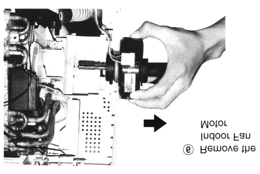
67 CS-MVG0KE / CU-MVGKE 7. Remove the transistor. (Two screws) (Fig.6) 8. Remove the diode. (One screws) (Fig.7) Fig. 6 Fig Removal procedure of The Propeller Fan and The Motor. Remove the cabinet top plate and the front grille. (Fig.0). Remove the propeller fan by rotating the nut at the center of the fan to the right. (Fig.8). Remove the control board cover (Front). (Fig.) Fig. 8 67
68 CS-MVG0KE / CU-MVGKE. Remove all connectors which are connected to the motor from the main control board..remove the motor by releasing four screws. (Fig.9) Fig. 9 68
69 CS-MVG0KE / CU-MVGKE Technical Data.. OPERATION CHARACTERISTICS 69
70 CS-MVG0KE / CU-MVGKE 70
71 CS-MVG0KE / CU-MVGKE Electronic Circuit Diagram.. HOW TO USE ELECTRONIC CIRCUIT DIAGRAM Before the circuit diagram, read the following carefully. Voltage measurement voltage has been measured with a digital tester when the indoor fan is set at high fan speed under the following conditions without setting the timer. Use them for servicing. Voltage indication is in Red at cooling and all operations. Voltage indication is in (Red) at heating. Indications for capacitor a. Unit µ... µf P... pf Indications for resistance Intake air temperature Temperature setting Discharge air temperature Pipe temperature Cooling 7 C 6 C 7 C C Heating 0 C 0 C 0 C 0 C a. K... KΩ M... MΩ W... wait Not indicated... / W Diode without indication... MA6 Circuit Diagram is subject to change without notice for further development... TIMER TABLE... Indoor Name Time Test Mode (When test point Shortcirculated) way valve abnormality min. 0 Outdoor air temp. for Hz No. detection 0 min. 0 Anti-freezing Control 6 min. 0 Theorem OFF delay min. 0 Low pressure control ( gas leakage ) compressor OFF time min. 0 Time delay safety control min. 8 sec. 0 Odor timer status shift time 0 sec sec. Hz lock time 0 sec. 0 Self diagnosis display time 0 sec. 0 Auto mode judgement sampling time 8 sec. 0 hours ON / OFF timer hour min. Hot start forced completion min. 0 Auto mode judgement interval 80 min. 80 sec. Sleep mode time shift hour 6sec. After Hot start / Deice min. sec.... Outdoor Name Time Test Mode (When test point Shortcirculated) DC PEAK 0 sec. sec. Deice detection 0 min. sec. 80 min. 8 sec. 0 min. 8 sec. 0 min. 8 sec. Deice forced completion min. 66 sec. Time delay safety control min. 0 Hz lock time 0 sec. 0 Outdoor fan delay operation control 0 sec. 0 way valve delay operation control min. 0 Standy control ON min. 8 sec. OFF 7 min. sec. 7
72 CS-MVG0KE / CU-MVGKE.. INDOOR UNIT CS-MVG0KE DISPLAY E9C99 G D0 ALNK7B R R R R6 D0 ALNK7 R7 R8 R9 R0 0Ω 9 R F E D C POWER FULL SLEEP TIMER R0 R0 R0 R0 R0 R06 R07 80Ω 7 ON/OFF POWER MONITOR g e a f b POWER MONITOR c CON d CON CON D.P 6 POWER MONITOR AW66FP VCC C0.µ QA QB QC R 7 QD QE CKS 6 QF 0 QG A 9 QH 8 QI CKL 8 7 QJ 6 QK 0 QL QM OE QN QO GND 9 QP IC0 R 00K C06 0.0µ C0 000P C0 000P C0 000P C0 000P POWER MONITOR D0 ALNM0A R09 00Ω R08 00Ω R0 00Ω R 00Ω POWER MONITOR RECEIVER A7 CN-DISP (MX9) CN-DISP C7 6V 0µ Q7 ADAXKTX SEGMENT DRIVE 0K.7K R K C 0.0µ IC APST600DR RESET Q8 ADAXKTX SEGMENT DRIVE 0K.7K C9 R 00P.K I G (V) TEST O R9 00K C 6V.µ Q0 ADAXKTX SEGMENT DRIVE R K 0K.7K ICX IC R R7 R9 R 0K A80A 0K 0K ABR900F 0K 8 DL SCK SCK RST 8 CS SO 6 SI 7 6 D0 D CS BUSY R 0K X ACTSMG0T MHz (7pFx) C6 0.0µ R6 9.9K 6 RECEPTION GND RESET GND POWER 7 8 TRANSMISSION OSC 9 SEGMENT DRIVE 0 6 GND FM-ROCK TEST IC A7866F0 SENSOR INPUT 7 REMOTE CONTROL 8 9 COMMAND INPUT POWER CLOCK INPUT TEMP POWER POWER GND 0 GND 0 C 000P R7.9K 9 8 R69 R 6.7K 0Ω C8 IC 6V 0µ AMPC9G AMP Q ADCXKTX BUZZER.7K 0K R K C6 0.µ C 600P C 000P R80.7K BZ A800 R8 K R 0K R8 0K D ASST 7 6 C IC 0V AMPC9G µ AMP LC A9AF0TL R0 BUZZER GND 80 R7 FAN MOTOR CONTROL 79 R77 78 FAN MOTOR CONTROL R K 7 7 R7 0K R 0K 68 AUTO 67 TEST RUN 66 STEPPING MOTOR 6 BZ D,D7,D8 ASST D D7 D8 R8 K J R 0K IC0 APS VCC VOUT GND R0 00Ω C0 6.V µ (MX) (MX) CN-RCV CN-RCV C7 6V.µ C 6V 7µ R0 0K R 0K PD Fig Fig Fig R 7Ω B A INTAKE AIR TEMP SENSOR (K 90) HEAT EXCHANGER TEMP SENSOR (0K 90) HEAT EXCHANGER TEMP SENSOR (0K 90) STEPPING MOTOR DRIVE SEQUENCE FOR CCW ROTATION VIEWED ON THE SHAFT (PH6) CN-TH Fig Fig Fig 6 (MX) CN-STM C6 0.0µ C9 6V 0µ R K C8 6V 0µ R.9K IC6 AA00GR 8 TRANSMISSION STEPPING MOTOR 6 9 C 6V 0µ R8.9K R0 0K C µ R 7Ω R6 0K R7 0K C 0.0µ C 0.0µ R K R6 K SW A009 AUTO SW A009 TEST RUN
73 CS-MVG0KE / CU-MVGKE IC8 AC08 (AWPC78W0A) +V REGULATOR O I C8 G 0.0µ C 6.V 00µ R9.K C 0.0µ R 0K R0 8.K C 0.0µ L L A80 A80 C9 00P R 0.Ω W C0 000P L C9 000P L A80 A80 IC7 AC08 SENSOR CIRCUIT 0 9 C V 70µ T 7 6.7V C6 0V 90µ C 0V µ D ASST R9.9K A0C00 DC/DC CONVERTER R8 9.9K C0 0V µ C 0V 68µ R6 0K Q ADAXKTX POWER CLOCK AMP Q.7K ADAXKTX POWER CLOCK AMP 0K R6 K C8 0.0µ R6.K.7K 0K DB ADSBA60F R67 00Ω C R6 7.K - C 000P C 0.µ PC AS0LKC PC R68 ATLP7LF 68OΩ R66 0Ω C 0VAC 0.0µ C 0VAC 0.0µ D ASST C 00P R70 00K R8 /W 8K R7.K LFI A9009 R79 /W 8K THI A7NDR R78 /W 0K R7 /W 0K D9 ADIF60 R8 /W 0K R8 /W 0K C0 0VAC 0.µ R7 /W 0K D ADIF60 R76 WS K ERZVEAV ZNR R7 /W K D6 ZNR ADIF60 ERZVA9V7 PC ATLPLBL FUSE T.A L0V (JL6) CN-PWR THERMAL FUSE THERMAL FUSE 0 C(A) TO OUTDOOR UNIT G F E D C6 000P C 000P C 000P C 000P R60 M LOGIC LOGIC SENSOR CIRCUIT LOGIC DRIVE CIRCUIT DRIVE CIRCUIT U V W FAN MOTOR DRIVE (GRN) (XH) CN-MTR MOTOR A98+M ELECTRONIC CONTROLLER (PC BOARD MAIN) A700 Resistance(kΩ) Fig. Sensor(Thermistor)Characteristics 70 Indoor Heat Exchanger Sensor & 60 Indoor Intake/Outdoor Air Sensor Outdoor Heat Exchanger Sensor, & Outdoor Pipe Sensor Voltage(V) Fig. Outdoor Air/Outdoor Heat Exchanger Temp. Outdoor Heat Exchanger Temp.Data Outdoor Air Temp.Data Fig. Compressor & DischangeTemp. Sensor(Thermistor)Characteristics C TERMINAL - VOLTAGE about 0ms about 80V about 0V Fan level FAN MOTOR STOP UV VW Between WU AC VOLTAGE 6V 0 U-GND V-GND W-GND DC VOLTAGE V Voltage(V) Fig. Intake Air/Indoor Heat Exchanger Temp. Intake Air Temp.Data Indoor Heat Exchanger Temp.Data Voltage(V) Fig. Total Running Current Data 0 0 Voltage(V) Fig.6 Compressor & Dischange Temp.Data B A
74 CS-MVG0KE / CU-MVGKE.. OUTDOOR UNIT G CU-MVGKE F E D C B 0V (0A) AC 0V 0Hz TERMINAL TO INDOOR UNIT -WAY VALVE -WAY VALVE AC WHT (YLW) (VH-) CN-HOT (VH-) CN-CV (GRN) (VH-) FAN MOTOR CN-FM (BLU) (VH-) CN-ROOMA (YLW) (XH6) CN-EVB OUTDOOR INTAKE (YLW) (XH-) AIR TEMP SENSOR (.96KΩ,800) CN-TH Fig FUSE0 L0V T.A C-FM A7 AC0 YLW AC9 BRW AC GRY AC BLK AC BLU CT A060 D ASST FUSE0 L0V T.0A TERMINAL C07 0V 700P D0 DIF60 (GRN) R (VH-) WS CN-ROOMB 9.K TERMINAL EXPANSION VALVE A EXPANSION VALVE B (XH6) CN-EVA 6 6 DISCHARGE TEMP (XH-) SENSOR (0KΩ,90) CN-DIS Fig C08 0V 700P CR0 CR0 THI A7S8RK0SB CR0 RY-L RY-PWR A009 D D D D0 DIF60 R0 /W K R06 /W 7K C0 00V µ R8 R /W /W K K D0 DIF60 IC0 AA00GR 6 C69 0.0µ A0007M R VR WS D0 00Ω 0K ERA-0 R7.99K 0 RY-HOT A0007M RY-CV A0007M C6 6V 0µ RY-AC A009 R.6K D R 90Ω C 0V 0µ ZNR00 ERZVEAV7 R WS 9.K 9 8 D6 D00 DIF60 R0 K R9 R0 /W /W K K 6 7 R W 68K R6 /W K R0 /W K DO0 ADSBA60F R97 WS 7K AEVMEASB R7.8K C 6V0µ R98 WS 7K C0 0V 0µ R /W K R /W K R9 /W 7K R W 68K R8 /W.7K R0 /W 7K R9.9K R7 /W.7K D-D6: ASST EXPANSION VALVE VR00 KΩ C09 000P ZD0 RD.6EB ZD0 RD.6EB C70 0.0µ LED00 R0 ASEC0IC 0Ω (GRN) PC00 R0 00K PS6E C0 00P PC0 TLP R.K C V µ PC TLP60 R00 00Ω R0 0K R 0K R8 IC V.80K µpc9 R.K R.K R.K R9.6K R0.K R90 0K C00 000P R9.0K R96.00K Fig6 Fig C 0.0µ C 0.0µ IC C 0.0µ IC C7 0V 0.7µ R 70K R6 0K IC07 µpc9 C6 000P ZNR0 R7 M ERZVEAV7 D0 DIF60 8 R07 K R.7K R6.7K R7.7K 0 R9 9.09K IC0 AA00GR IC R9 99Ω PC TLP PC TLP PC0 TLP R09.0K C6 000P C6 0Vµ PC0 PS6E R0 00K C0 00P R08 PC0 00Ω TLP LED0 ASEC0IC R 0Ω (GRN) 9 8 R 0K C 0.0µ R9 0K R00.00K 6 R8 0K C0 0.0µ IC07 7 R09 0K R9.K C0 000P EXPANSION VALVE LED No. Color Function LED00 Green Data Transmission A LED0 Green Data Transmission B LED0 Orange Heating LED0 Green Cooling LED Orange Power ON IC06 ATC0FEL Y0 VD 6 Y X Y X Y X Y X0 6 INH X 7 VCC A 0 8 VSS B 9 R77 0K C8 6.V 00µ R6 0K R6 0K C60 0.0µ R60 0K C6 0.0µ C7 0.0µ ICX A8 R7 0K R7 0K 7 S CS SCK DL VCC VCC 8 6 SO GND C6 6V.µ LED0 ASEC0IC R6 COOLING (GRN) 60Ω R6 LED0 60Ω ASEC80IC HEATING (ORG) R76 0K X ACCCMH0T MHz (7pFx) R9 0K C7 0.0µ C9 000P R8 0K GND 80 POWER GND OSC RESET R 0K R 0K R6 0K R7 0K 7 IC A6BFN7 GND R6 0K 68 EXPANSION VALVE R7 0K 67 R K 66 6 OUTDOOR INTAKE AIR TEMP SENSOR DISCHARGE TEMP SENSOR TEST R 0K R 0K GND POWER GND TEST(MH) C 6.V 00µ A
75 CS-MVG0KE / CU-MVGKE G P N T0 A077 R68 0K C 000P D G E F Q00 DAXK RECEPTION Q0 DAXK TRANSMISSION C6 6.V 00µ C9 0.0µ X ACCC6MH0T 6MHz (pfx) C 0.0µ C8 0.0µ RY-PWR RY-AC RY-HOT RY-CV R9 0K R9 0K RY-L C IC APST600DR I ICX A806 O G R87 0K R 0K C6 000P Q DAXK RECEPTION Q9 DAXK TRANSMISSION R88 00K C0 6V.µ IC6 AA00GR S CS SCK DL VCC VCC 8 6 SO GND R9 0K C 0.0µ R00 D00 IC00 ZD00 L00 D00 C00 C R90 0K C 0.0µ D SC0-6 D6 SC0- D7 SC0- H D SC0- C D C0 ECFS V 0µ B D0 ECFS A 7 D SC0-8 R 68Ω 80 C8 V 70µ R0 68Ω 79 R9 68Ω 78 C V 0µ C V 0µ C6 V 0µ C9 V 0µ R8 K R K R8 68Ω C V 70µ 77 R7 68Ω 76 R /W.6K R /W.6K R /W.6K R6 /W.6K R0 60Ω LED ASEC80IC POWER ON (ORG) R /W.6K R /W.6K R /W.6K R7 /W.6K R /W0Ω R6 /W0Ω R7 /W0Ω R8 /W0Ω R6 68Ω POWER TRANSISTOR BASE SIGNAL OUTPUT RECEPTION TRANSMISSION RESET 9 POWER 0 OSC GND WAY 9 VALVE 0 -WAY VALVE RY-PWR RY-LO R9 /W.6K GND C0 /W.6K R 0K I O C 0.0µ G C7 0.0µ R0 0K 70 C 6V.µ IC0 S0NAF IC0 S00NAF I IC08 S0NAF I O C 0.0µ G 69 G IC AD9G09 xfhz RY-AC R 0K O 68 R 0K GND C8 0.0µ DC PEAK R0 0K C 0.0µ C6 0.0µ C 6.V 00µ C6 0.0µ 6 C7 6.V00µ R00.k 6 GND C V 00µ C8 0.0µ C V 00µ 6 6 R9 K TEST 6 R0 K R86 8K CURRENT COMP TEMP OUTDOOR TEMP HEAT EXCHANGER HEAT EXCHANGER CN-B TEST POWER GND R97 0K R98 0K Q DAXK Q0 DAYK PC TLP R 0K C7 0.0µ Fig Fig6 Fig Fig Fig C 0.0µ C87 000P R0 0K JP STAND BY R 0K R99 0.0K R0 0K R89 K R9 0K C 0.0µ C6 6.V 00µ C9 000P (RED) (XH) CN-U (BLU) (XH) CN-V (YLW) (XH) CN-W (XH) CN-L R7.6K C 00P (RED) (XH) CN-U (BLU) (XH) CN-V (YLW) (XH) CN-W (XH8) (XH8) CN-PWM CN-PWM R7.6K C 00P C V 7µ C V 7µ C V 7µ C (XH) V CN-L 00µ PC TLPLF R 60Ω R 60Ω R 60Ω Q6 AG0J0B C 0.µ R68 /W 0Ω R70 /W 0Ω PC TLP(GR) PC TLP(GR) PC TLP(GR) PC PC R80 /W 90Ω R8 /W 90Ω R 60Ω R 60Ω PC6 TLP (GR) TLP (GR) TLP (GR) R6 60Ω R7.7K R7.7K R66 M R7 R6.7K 8 K Q IC7 SA6 R67 M R76.7K 7 6 Q SA6 IC7 µpc9 µpc9 R6 K VIN VCC GND VFO TEMP VIN CT VOUT VCC VSS GND VFO TEMP VIN CT VOUT VCC VSS GND VFO TEMP VIN CT VOUT VCC VSS GND VFO TEMP VIN CT VOUT VCC VSS GND VFO TEMP CT VIN VOUT VCC VSS GND GND VFO TEMP D7 D8 D9 CT VOUT VSS GND GND GND GND GND D D6 D0 ASST D-D0: ASST R0.8K C70 0.0µ R6.00M C0 8P R9.00M C 8P R6.00M C 8P C68 6V 0µ R /W K R7.0K R8 /W K R60.0K R6 /W K R6.0K R8.0K R77 /W 69K R78 /W 69K R79 /W 69K C66 6V 0µ C6 6V 0µ R9.8K C67 6V 0µ R7.99K R R6 K 0K C 60V µ U V W (GRN) (XH) CN-TH (YLW) (XH) CN-TH (NV-) CN-TANK (NH) CN-S COMP TRANSISTOR MODULE(IPM) AC00 (A7090) ELECTRONIC CONTROLLER (PC BOARD MAIN) A70 Fig Fig Fig Fig HEAT EXCHANGER TEMP SENSOR (.96KΩ.800) HEAT EXCHANGER TEMP SENSOR (.96KΩ.800) OUTDOOR AIR TEMP SENSOR (KΩ.90) COMP TEMP SENSOR (0KΩ.90) F E D C B A
76 CS-MVG0KE / CU-MVGKE.. REMOTE CONTROLLER G REMOTE CONTROLLER WIRELESS REMOTE CONTROL CWA 7C00 R 0kΩ R 0kΩ R6 0kΩ F D ARBDT + C0 7µ C 0.µ X.MHz SEG 0 SEG TP6 SEG SEG E D C R0 x TP TP C 0.µ RESET terminal + C 7µ R.Ω (8G) TP TP7 D SID00 Q D8 R kω C p C 0p TP7 R8 0kΩ X.768kHz A TP8 TP9 Door SW (CLOSE:ON) B SW J TP0 TP TP TP 7 X0 8 X 9 VSS 0 RES P0 P P P P00 6 P0 7 P0 8 P0 9 P0 0 P P P TP OSC OSC VDD VLCD VLCD VLCD COM 0 COM COM SEG 0 SEG SEG SEG SEG SEG P0 P P P P0 RMO SEG SEG TP TP TP 8 SEG 0 7 IC SBL0M MICROCOMPUTER SEG 9 6 SEG 8 SEG 7 SEG 6 SEG SEG SEG 6 SEG 7 6 SEG 8 6 SEG 9 6 SEG 0 6 SEG 60 SEG 9 SEG 8 SEG 7 SEG 6 SEG 6 SEG 7 SEG 8 SEG 9 SEG 0 SEG 0 SEG 9 SEG 8 TP6 SEG SEG SEG 6 SEG 7 SEG 8 SEG 9 SEG 0 SEG SEG SEG SEG SEG SEG 6 SEG 7 SEG 8 COM COM COM 0 SEG 9 SEG 0 SEG SEG SEG SEG COM COM COM 0 SEG LIQUID CRYSTAL DISPLAY SET OFF-TIMER FAN SPEED (TEMP ) SEG 6 SEG 7 SEG 8 CANCEL ON-TIMER SEG 9 SEG 0 SEG B TEST SLEEP (POWERFUL) AIR SWING MANUAL (OFF/ON) AIR SWING AUTO MODE (TEMP ) CLOCK REMOTE CONTROLLER NO. 0 <SW> SIDE A : OFF SIDE B : ON SW OFF ON OFF ON J SHORT SHORT SEG A


 (")
77 CS-MVG0KE / CU-MVGKE Printed Circuit Board.. INDOOR UNIT CS-MVG0KE Main PCB ( Front Side ) Display PCB ( Front Side ) ( Back Side ) 77

")
78 CS-MVG0KE / CU-MVGKE CS-MVG0KE Main PCB ( Back Side ) Receiver PCB 78
 79 CS-MVG0KE /")
79 .. OUTDOOR UNIT / MAIN PCB CU-MVGKE Main PCB ( Front Side ) 79 CS-MVG0KE / CU-MVGKE

80 CS-MVG0KE / CU-MVGKE CU-MVGKE Main PCB ( Back Side ) 80

 (")
81 CS-MVG0KE / CU-MVGKE.. OUTDOOR UNIT / TRANSISTOR MODULE CU-MVGKE Transistor Module PCB ( Front Side ) ( Back Side ) 8
Room Air Conditioner CONTENTS CS-E18CKE CU-E18CKE CS-E21CKE CU-E21CKE. Order No. MAC C2
 Order No. MAC00801C Room Air Conditioner CS-E18CKE CU-E18CKE CS-E1CKE CU-E1CKE CONTENTS Page Page 1 Features Functions Product Specifications 6 4 Dimensions 10 5 Refrigeration Cycle Diagram 1 6 Block Diagram
Room Air Conditioner CONTENTS CS-PV9CKE CU-PV9CKE CS-PV12CKE CU-PV12CKE
 Order Number: GMAC0311008C2 Room Air Conditioner CS-PV9CKE CU-PV9CKE CS-PV12CKE CU-PV12CKE CONTENTS Page Page 1 Functions 2 2 Product Specifications 5 3 Dimensions 9 4 Refrigeration Cycle Diagram 11 5
Air Conditioner CONTENTS CS-TE9DKE CU-TE9DKE CS-TE12DKE CU-TE12DKE. Order No. RAC C2
 Order No. RAC0502005C2 Air Conditioner CS-TE9DKE CU-TE9DKE CS-TE12DKE CU-TE12DKE CONTENTS Page Page 1 Features 2 2 Functions 3 2.1. Remote Control 3 2.2. Indoor Unit 4 2.3. Outdoor unit 5 3 Product Specifications
Room Air Conditioner CONTENTS CS-E9BKP CU-E9BKP5 CS-E12BKP CU-E12BKP5. Order No: MAC C2
 Order No: MAC008C Room Air Conditioner CS-E9BKP CU-E9BKP5 CS-EBKP CU-EBKP5 CONTENTS Page Page Features Functions Product Specifications 6 Dimensions 0 5 Refrigeration Cycle Diagram 6 Block Diagram 7 Wiring
Air Conditioner CONTENTS CS-E18EKU CU-E18EKU CS-E21EKU CU-E21EKU. Order No: MAC C1
 Order No: MAC0512115C1 CS-E18EKU CU-E18EKU CS-E21EKU CU-E21EKU Air Conditioner CONTENTS Page Page 1 Safety Precautions 3 2 Specification 5 2.1. CS-E18EKU CU-E18EKU 5 2.2. CS-E21EKU CU-E21EKU 7 3 Location
TABLE OF CONTENTS. Air Conditioner CS-NE7GKE CU-NE7GKE CS-NE9GKE CU-NE9GKE CS-NE12GKE CU-NE12GKE
 Order No. MAC0705021C2 Air Conditioner CS-NE7GKE CU-NE7GKE CS-NE9GKE CU-NE9GKE CS-NE12GKE CU-NE12GKE TABLE OF CONTENTS PAGE 1 Safety Precaution ------------------------------------------------ 2 2 Specifications
CS-XE9EKE CU-XE9EKE CS-XE12EKE CU-XE12EKE
 Order No. MAC0512111C8 Air Conditioner CS-XE9EKE CU-XE9EKE CS-XE12EKE CU-XE12EKE TABLE OF CONTENTS PAGE 1 Safety Precautions----------------------------------------------- 3 2 Specifications -----------------------------------------------------
TABLE OF CONTENTS. Air Conditioner CS-E24GKES CU-E24GKE CS-E28GKE CU-E28GKE
 Order No. MAC0701008C2 CS-E24GKES CU-E24GKE CS-E28GKE CU-E28GKE Air Conditioner TABLE OF CONTENTS PAGE 1 Safety Precautions----------------------------------------------- 2 2 Specifications -----------------------------------------------------
TABLE OF CONTENTS. Air Conditioner CS-MRE12MKE
 Order No. PHAAM1103074C8 Indoor Unit CS-MRE7MKE CS-MRE9MKE CS-MRE12MKE Air Conditioner Outdoor Unit CU-2RE15MBE CU-2RE18MBE TABLE OF CONTENTS PAGE 1 Safety Precautions-----------------------------------------------
1. ACCESSORIES SUPPLIED WITH THE AIR CONDITIONER 2. LOCATION OF INDOOR AND OUTDOOR UNIT 3. INSTALLATION/SERVICE TOOLS (ONLY FOR R410A PRODUCT) 4.
 4.") 1. ACCESSORIES SUPPLIED WITH THE AIR CONDITIONER 2. LOCATION OF INDOOR AND OUTDOOR UNIT 3. INSTALLATION/SERVICE TOOLS (ONLY FOR R410A PRODUCT) 4. INSTALLATION OF THE INDOOR UNIT 5. CONDENSATE HOSE CONNECTION
1. ACCESSORIES SUPPLIED WITH THE AIR CONDITIONER 2. LOCATION OF INDOOR AND OUTDOOR UNIT 3. INSTALLATION/SERVICE TOOLS (ONLY FOR R410A PRODUCT) 4. INSTALLATION OF THE INDOOR UNIT 5. CONDENSATE HOSE CONNECTION
CU-3E23CBPG, CU- 4E27CBPG,
 Order No. PHAAM0810051C2 Air Conditioner Indoor Unit Outdoor Unit CS-E7JKEW CU-E7JKE CS-E9JKEW CU-E9JKE CS-E12JKEW CU-E12JKE CS-E15JKEW CU-E15JKE CS-E15JKEW CU-E15JKE-1 CS-E7JKEW-3 CU-E7JKE-3 CS-E9JKEW-3
Air Conditioner CONTENTS CS-E9DKEW CU-E9DKE CS-E12DKEW CU-E12DKE. Order No: MAC C2
 Order No: MAC041064C CS-E9DKEW CU-E9DKE CS-E1DKEW CU-E1DKE Air Conditioner CONTENTS Page Page 1 Features Functions 3.1. Remote Control 3.. Indoor Unit 4.3. Outdoor Unit 6 3 Product Specifications 7 3.1.
AOYG18LFC OUTDOOR UNIT INSTALLATION MANUAL INSTALLATION MANUAL. For authorized service personnel only. PART NO
 AOYG8LFC OUTDOOR UNIT INSTALLATION MANUAL INSTALLATION MANUAL For authorized service personnel only. English PART NO. 93778639 93778639_IM.indb /20/20 6:07:25 PM AIR CONDITIONER OUTDOOR UNIT INSTALLATION
1 TECHNICAL CHANGES. MUZ-A09NA MUZ-A09NA - 1 MUZ-A09NA - U1 MUZ-A09NA - U2 1. Refrigerant system diagram has been changed.
 1 TECHNICAL CHANGES MUZ09UN MUZ-A09NA MUZ12UN MUZ-A12NA MUH15TN MUZ-A15NA MUH17TN MUZ-A17NA MUH24WN MUZ-A24NA MU15TN MUY-A15NA MU17TN MUY-A17NA MU24WN MUY-A24NA 1. Outdoor unit model has been changed.
AUTO COOL DRY FAN SPEED AIR SWING OFF ON TIMER TIMER OFF/ON FAN SPEED MODE TEMP AIR SWING TIMER ON SET OFF CANCEL AC RC SET CHECK CLOCK RESET
 AUTO COOL DRY MODE TIMER ON OFF TIMER OFF/ON TEMP ON TIMER FAN SPEED AIR SWING SET 1 2 3 FAN SPEED AIR SWING OFF CANCEL AC RC SET CHECK CLOCK RESET Order No: PAPAMY1611008CE Indoor Unit CS-MPS9SKH CS-MPS12SKH
CU-S9NKV-7 CU-S12NKV-7 CU-S18NKV-7 CU-S22NKV-7 CS-S9NKV-7 CS-S12NKV-7 CS-S18NKV-7 CS-S22NKV-7 WARNING
 Order No: PAPAMY1206010CE Indoor Unit CS-S9NKV-7 CS-S12NKV-7 CS-S18NKV-7 CS-S22NKV-7 Outdoor Unit CU-S9NKV-7 CU-S12NKV-7 CU-S18NKV-7 CU-S22NKV-7 WARNING This service information is designed for experienced
CS-E18NKUA CS-E24NKUA CU-E18NKUA CU-E24NKUA TABLE OF CONTENTS WARNING
 Order No: PAPAMY1204088CE Indoor Unit CS-E18NKUA CS-E24NKUA Outdoor Unit CU-E18NKUA CU-E24NKUA WARNING This service information is designed for experienced repair technicians only and is not designed for
TABLE OF CONTENTS. Air Conditioner. Indoor Unit Outdoor Unit CS-NE9LKE CU-NE9LKE CS-NE12LKE CU-NE12LKE CS-XE9LKE-5 CU-NE9LKE CS-XE12LKE-5 CU-NE12LKE
 Order No. PHAAM1007139C2 Air Conditioner Indoor Unit Outdoor Unit CS-NE9LKE CU-NE9LKE CS-NE12LKE CU-NE12LKE CS-XE9LKE-5 CU-NE9LKE CS-XE12LKE-5 CU-NE12LKE TABLE OF CONTENTS PAGE 1 Safety Precautions-----------------------------------------------
CS-RE9JKX-1 CS-RE12JKX-1 CS-RE15JKX-1 CU-RE9JKX-1 CU-RE12JKX-1 CU-RE15JKX-1 TABLE OF CONTENTS WARNING
 Order No: PHA-AG1002007C2 Indoor Unit CS-RE9JKX-1 CS-RE12JKX-1 CS-RE15JKX-1 Outdoor Unit CU-RE9JKX-1 CU-RE12JKX-1 CU-RE15JKX-1 WARNING This service information is designed for experienced repair technicians
CS-UE9PKE CS-UE12PKE CU-UE9PKE CU-UE12PKE TABLE OF CONTENTS WARNING
 Order No: PAPAGZ121215CE Indoor Unit CS-UE9PKE CS-UE12PKE Outdoor Unit CU-UE9PKE CU-UE12PKE WARNING This service information is designed for experienced repair technicians only and is not designed for
INVERTER WALL MOUNTED TYPE ROOM AIR-CONDITIONER (Split system, air to air heat pump type)
") TECHNICAL MANUAL & PARTS LIST DRAFT INVERTER WALL MOUNTED TYPE ROOM AIR-CONDITIONER (Split system, air to air heat pump type) SRK20ZD-S - 1 - INDOOR UNIT Model SRK20ZD-S OUTDOOR UNIT Model SRC20ZD-S REMOTE
TECHNICAL MANUAL & PARTS LIST DRAFT INVERTER WALL MOUNTED TYPE ROOM AIR-CONDITIONER (Split system, air to air heat pump type) SRK20ZD-S - 1 - INDOOR UNIT Model SRK20ZD-S OUTDOOR UNIT Model SRC20ZD-S REMOTE
CU-YE9MKE CU-YE12MKE CU-YE18MKE CS-YE9MKE CS-YE12MKE CS-YE18MKE TABLE OF CONTENTS WARNING
 Order No: PHA-AG1102003C2 Indoor Unit CS-YE9MKE CS-YE12MKE CS-YE18MKE Outdoor Unit CU-YE9MKE CU-YE12MKE CU-YE18MKE WARNING This service information is designed for experienced repair technicians only and
Split-type Air-Conditioner INSTALLATION MANUAL CONTENTS FOR INSTALLER MXZ-3B54VA MXZ-4B71VA. English
 Split-type Air-Conditioner MXZ-3B54VA MXZ-4B71VA INSTALLATION MANUAL English Refer to the installation manual of each indoor unit for indoor unit installation. IMPORTANT NOTES TO COMPLY WITH THE REQUIREMENTS
IMPORTANT SAFETY NOTICE
 Order No: PAPAMY703052CE Indoor Unit CS-TE20TKEW CS-TE25TKEW CS-TE35TKEW CS-TE42TKEW Outdoor Unit CU-TE20TKE CU-TE25TKE CU-TE35TKE CU-TE42TKE Destination Europe Turkey Please file and use this manual together
Air Conditioner CONTENTS
 ORDER NO. MAC0509068C2 Air Conditioner CS-F24DD1E5 CU-B24DBE5 CS-F28DD1E5 CU-B28DBE5 CS-F28DD1E5 CU-B28DBE8 CS-F34DD1E5 CU-B34DBE5 CS-F34DD1E5 CU-B34DBE8 CS-F43DD1E5 CU-B43DBE8 CS-F50DD1E5 CU-B50DBE8 CONTENTS
INSTALLATION MANUAL SPLIT TYPE ROOM AIR CONDITIONER (PART NO )
") SPLIT TYPE ROOM AIR CONDITIONER INSTALLATION MANUAL (PART NO. 9312791019-01) This air conditioner uses new refrigerant HFC (R410A). The basic installation work procedures are the same as conventional refrigerant
SPLIT TYPE ROOM AIR CONDITIONER INSTALLATION MANUAL (PART NO. 9312791019-01) This air conditioner uses new refrigerant HFC (R410A). The basic installation work procedures are the same as conventional refrigerant
INSTALLATION MANUAL. Split-type Air Conditioner (Cooling and Heating) Indoor Unit AQB18J6WC AQB24J2WC. Outdoor Unit UQB18J6WC UQB24J2WC
 Indoor Unit AQB18J6WC AQB24J2WC. Outdoor Unit UQB18J6WC UQB24J2WC") AQB8J6WC_IM_E_25864 2006.4.4 3:29 PM Page 7 INSTALLATION MANUAL Indoor Unit AQB8J6WC AQB24J2WC Outdoor Unit UQB8J6WC UQB24J2WC ENGLISH FRANÇAIS ESPAÑOL Split-type Air Conditioner (Cooling and Heating)
AQB8J6WC_IM_E_25864 2006.4.4 3:29 PM Page 7 INSTALLATION MANUAL Indoor Unit AQB8J6WC AQB24J2WC Outdoor Unit UQB8J6WC UQB24J2WC ENGLISH FRANÇAIS ESPAÑOL Split-type Air Conditioner (Cooling and Heating)
WALL MOUNTED TYPE ROOM AIR-CONDITIONER
 TECHNICAL MANUAL & PARTS LIST DRAFT WALL MOUNTED TYPE ROOM AIR-CONDITIONER (Split system, air to air heat pump type) SRK50HE-S, SRK56HE-S (Split system, air cooled cooling only type) SRK50CE-S, SRK56CE-S
Air Conditioner CONTENTS CS-V18DKE CU-V18DKE CS-V24DKE CU-V24DKE. Order No. MAC C2
 Order No. MAC0410044C2 CS-V18DKE CU-V18DKE CS-V24DKE CU-V24DKE Air Conditioner CONTENTS Page Page 1 Features 2 2 Functions 3 2.1. Remote Control 3 2.2. Indoor Unit 4 2.3. Outdoor Unit 5 3 Product Specifications
AUT O HE AT COOL DRY FAN SPEE D AIR SW ING OFF/ON MODE TEMP AIR SW ING POWERFUL/ QUIET TIMER ON SET OFF CANCEL SET CHECK CLOCK RESET WARNING
 AUT O HE AT COOL DRY POWERFUL/ QUIET FAN SPEE D AC AIR SW ING SET CHECK CLOCK RESET FAN SPEED AIR SW ING RC Order No: PAPAMY502046CE Indoor Unit CS-RE9RKEW CS-RE2RKEW CS-RE5RKEW Outdoor Unit CU-RE9RKE
INSTALLATION MANUAL. Split-type Air Conditioner (Cooling and Heating) Outdoor Unit UQB09JJWC UQB12JJWC. Indoor Unit AQB09JJWC AQB12JJWC
 Outdoor Unit UQB09JJWC UQB12JJWC. Indoor Unit AQB09JJWC AQB12JJWC") AQB09JJ6WC_IM_E_2585 2006.4.17 4:26 PM Page 17 INSTALLATION MANUAL Indoor Unit AQB09JJWC AQB12JJWC Outdoor Unit UQB09JJWC UQB12JJWC ENGLISH FRANÇAIS ESPAÑOL Split-type Air Conditioner (Cooling and Heating)
AQB09JJ6WC_IM_E_2585 2006.4.17 4:26 PM Page 17 INSTALLATION MANUAL Indoor Unit AQB09JJWC AQB12JJWC Outdoor Unit UQB09JJWC UQB12JJWC ENGLISH FRANÇAIS ESPAÑOL Split-type Air Conditioner (Cooling and Heating)
Split-type Air-Conditioner
 Split-type Air-Conditioner MXZ-2C52VA Installation Manual For INSTALLER This manual only describes the installation of outdoor unit. When installing the indoor unit, refer to the installation manual of
AIR CONDITIONER CONSOLE
 Installation manual ENGLISH AIR CONDITIONER CONSOLE English Indoor unit console type IT IS MANDATORY TO CUT OFF POWER SUPPLY BEFORE STARTING TO WORK IN THE ELECTRIC CASING BOXES. GENERAL RECOMMENDATIONS
Split-type Air-Conditioner
 Split-type Air-Conditioner MXZ-2D52VA Installation Manual For INSTALLER This manual only describes the installation of outdoor unit. When installing the indoor unit, refer to the installation manual of
Installation Manual PMV Kit RBM-PMV0363E RBM-PMV0903E
 EB99802801-1 Installation Manual RBM-PMV0363E RBM-PMV0903E Installation Manual English OUTDOOR UNIT SIDE UPPER INDOOR UNIT SIDE Thank you very much for purchasing TOSHIBA Air conditioner. Please read this
TABLE OF CONTENTS. Air Conditioner
 Order No. MAC0804027A2 Air Conditioner CS-E9GFEW-2 CU-E9GFE-2 CS-E12GFEW-2 CU-E12GFE-2 CS-E18GFEW-2 CU-E18GFE-2 CU-2E15GBE CU-3E18EBE CU-3E23CBPG CU-4E27CBPG Please file and use this manual together with
WALL MOUNTED type SPLIT TYPE ROOM AIR CONDITIONER CONTENTS. Models
 SPLIT TYPE ROOM AIR CONDITIONER WALL MOUNTED type Models Indoor unit ASY9USCCW ASY9USCCW ASY12USCCW Outdoor unit AOY9USCC AOY9UFCC AOY12USCC CONTENTS SPECIFICATIONS................................... 1
Split-type Air-Conditioner
 Split-type Air-Conditioner MXZ-2E52VAD MXZ-3E54VAD MXZ-4E71VAD Installation Manual For INSTALLER This manual only describes the installation of outdoor unit. When installing the indoor unit, refer to the
CU-RE18RKE CU-RE24RKE CS-RE18RKEW CS-RE24RKEW. Destination Europe L.America Turkey WARNING
 Order No: PAPAMY502047CE Indoor Unit CS-RE8RKEW CS-RE24RKEW Outdoor Unit CU-RE8RKE CU-RE24RKE Destination Europe L.America Turkey WARNING This service information is designed for experienced repair technicians
DC INVERTER SPLIT SYSTEM AIR CONDITIONER
 AIR CONDITIONER TECHNICAL & SERVICE MANUAL KS1872 + C1872 + CL1872 KS2472 + C2472 + CL2472 FILE NO. Destination: North America DC INVERTER SPLIT SYSTEM AIR CONDITIONER Indoor Model No. KS1872 KS2472 Product
TECHNICAL DATA & SERVICE MANUAL MTF94C5TAA
 TECHNICAL DATA & SERVICE MANUAL MTF94C5TAA 0.8180.472.0 07/2005 Page 1. SPECIFICATIONS 3 1-1 Unit Specifications 3 1-2 Major Component Specifications 4 2. DIMENSIONAL DATA 6 2-1 Unit Dimensions 6 3. ELECTRICAL
AIR CONDITIONER CASSETTE
 Installation manual AIR CONDITIONER CASSETTE English Part Number: 453195200/03 10. REFRIGERANT TUBING...17 11. PANEL INSTALLING...19 12. SPECIAL SETTINGS...22 13. SELF DIAGNOSTICS...23 14. FINAL TASKS...26
AIR CONDITIONER CASSETTE
 Installation manual AIR CONDITIONER CASSETTE English 10. REFRIGERANT TUBING...17 11. PANEL INSTALLING...19 12. FINAL TASKS...21 1 1. REQUIRED TOOLS FOR INSTALLATION WORK 2. SAFETY PRECAUTIONS Installation
R410A. WALL MOUNTEDtype INVERTER SPLIT TYPE ROOM AIR CONDITIONER. Models Indoor unit Outdoor unit AO*R07LGC AO*R09LGC AO*R12LGC AO*R14LGC
 SERVICE INSTRUCTION SPLIT TYPE ROOM AIR CONDITIONER WALL MOUNTEDtype INVERTER Models Indoor unit Outdoor unit AS*A07LGC AS*A09LGC AS*A2LGC AS*A4LGC AO*R07LGC AO*R09LGC AO*R2LGC AO*R4LGC R40A CONTENTS.
DC INVERTER MULTI-SYSTEM AIR CONDITIONER
 TECHNICAL & SERVICE MANUAL OUTDOOR UNIT : CU-3KE19NBU CU-4KE24NBU CU-4KE31NBU DC INVERTER MULTI-SYSTEM AIR CONDITIONER Capacity at 0V 19,100 BTU/h,200 BTU/h 30,600 BTU/h Outdoor Model No. CU-3KE19NBU CU-4KE24NBU
YC ON-OFF SERIES. Service Manual
 YC ON-OFF SERIES Service Manual CONTENTS 1. Precaution... 3 1.1 Safety Precaution... 3 1.2 Warning... 3 2. Model Lists... 6 3. Dimension... 7 3.1 Indoor Unit... 7 3.2 Outdoor Unit... 11 4. Refrigerant
SERVICE MANUAL ROOM AIR CONDITIONER TAN/TAG-A28FWIS TAN/TAG-A32FWIS CONTENTS
 SERVICE MANUAL ROOM AIR CONDITIONER TAN/TAG-A28FWIS TAN/TAG-A32FWIS CONTENTS SPECIFICATION... 1 FUNCTIONS... 5 SERVICE FUNCTION EXPLANATION... 7 OPERATION DETAILS... 8 TROUBLESHOOTING GUIDE... 13 PERFORMANCE
38VYX110/38VYX130 I S O INSTALLATION MANUAL
 LLOYD'S REGISTER QUALITY ASSURANCE 38VYX110/38VYX130 I S O 9 00 1 INSTALLATION MANUAL Heat pump split system outdoor units For operation and maintenance instructions of this unit as well as installation
SERVICE MANUAL MUFZ-KJ50VE - E1, E2, ER1, ER2, ET1, ET2 MUFZ-KJ35VE OUTDOOR UNIT. No. OBH667. Models HFC
 Revision D: MUFZ-KJ25VE - E2, ER2, ET2, MUFZ- KJ35VE - E2, ER2, ET2 and MUFZ- KJ50VE - E2, ER2, ET2 have been added. Please void OBH667 REVISED EDITION-C. OUTDOOR UNIT SERVICE MANUAL HFC utilized R410A.
SERVICE MANUAL MUZ-FH25VE MUZ-FH35VE MUZ-FH50VE OUTDOOR UNIT. No. OBH624. Models HFC. Revision A: MUZ-FH50VE- E1 has been added. Please void OBH624.
 SPLIT-TYPE AIR CONDITIONERS Revision A: MUZ-FH50VE- E1 has been added. Please void OBH624. OUTDOOR UNIT SERVICE MANUAL HFC utilized R410A. OBH624 REVISED EDITION-A Models MUZ-FH25VE MUZ-FH35VE MUZ-FH50VE
[FLARE CONNECTION TYPE] ATTENTION
![[FLARE CONNECTION TYPE] ATTENTION](/thumbs/88/117511702.jpg "[FLARE CONNECTION TYPE] ATTENTION") SPLIT-TYPE AIR CONDITIONERS Model MXZ-2A20NA [FLARE CONNECTION TYPE] HFC utilized R410A INSTALLATION MANUAL ATTENTION This manual mentions how to install only the outdoor unit, MXZ-2A20NA. As for the way
SPLIT-TYPE AIR CONDITIONERS Model MXZ-2A20NA [FLARE CONNECTION TYPE] HFC utilized R410A INSTALLATION MANUAL ATTENTION This manual mentions how to install only the outdoor unit, MXZ-2A20NA. As for the way
AIR CONDITIONER FLOOR CEILING
 Installation manual ENGLISH AIR CONDITIONER FLOOR CEILING English Indoor unit floor ceiling type FCD / TCD /DCF IT IS MANDATORY TO CUT OFF POWER SUPPLY BEFORE STARTING TO WORK IN THE ELECTRIC CASING BOXES.
TECHNICAL & SERVICE MANUAL WINDOW TYPE AIR CONDITIONER SA 183A FILE NO. SA 183A REFERENCE NO. SM Destination Australia SA-183A
 TECHNICAL & SERVICE MANUAL SA 183A FILE NO. WINDOW TYPE AIR CONDITIONER Model No. Product Code No. SA-183A 1 851 006 96 Destination Australia SA 183A REFERENCE NO. SM700514 IMPORTANT! Please Read Before
1. General Description
 1. General Description A: SPECIFICATIONS 1. HEATER SYSTEM Heating capacity 2. A/C SYSTEM AUTO A/C MODEL Item Specifications Condition 5.0 kw (4,300 kcal/h, 17,062 BTU/h) or more AC-2 Mode selector switch:
SRK20ZFX-S, 25ZFX-S, 35ZFX-S, 50ZFX-S
 Manual No. 06. SRK-T. 051 TECHNICAL MANUAL Collection data INVERTER WALL MOUNTED TYPE ROOM AIR-CDITIER ( Split system, air to air heat pump type ) SRK20ZFX-S, 25ZFX-S, 35ZFX-S, 50ZFX-S CTENTS 1. GENERAL
TECHNICAL & SERVICE MANUAL WINDOW TYPE AIR CONDITIONER SA 123A FILE NO. SA 123A REFERENCE NO. SM700513
 TECHNICAL & SERVICE MANUAL SA 123A FILE NO. WINDOW TYPE AIR CONDITIONER Model No. Product Code No. Destination SA-123A 1 851 006 95 Australia SA 123A REFERENCE NO. SM700513 IMPORTANT! Please Read Before
HFC 1. THE FOLLOWING SHOULD ALWAYS BE OBSERVED FOR SAFETY 2. SELECTING THE INSTALLATION LOCATION R410A INSTALLATION MANUAL
 SG79Y427H02 INSTALLATION MANUAL SPLIT-TYPE AIR CONDITIONERS Models MSZ-GA22/GA25/GA35VA Series MUZ-GA25/GA35VA [FLARE CONNECTION TYPE] HFC utilized R410A When installing an MXZ series outdoor unit, refer
Westinghouse. Split System Inverter Series. Service Manual
 Westinghouse Split System Inverter Series Service Manual Model: WIWPK/WCHPK Range: 2.6kw 7.6kw CONTENTS 1. Precaution... 1 1.1 Safety Precaution... 1 1.2 Warning... 1 2. Function... 5 3. Dimension... 6
Air-to-Water Hydromodule + Tank WH-UX12FE5 WH-UD12FE5 WH-UD16FE5. Destination Europe WARNING
 Order : PAPAMY420CE Air-to-Water Hydromodule + Tank Indoor Unit WH-ADC26G6E5 Outdoor Unit WH-UX09FE5 WH-UX2FE5 WH-UD2FE5 WH-UD6FE5 Destination Europe WARNING This service information is designed for experienced
TECHNICAL & SERVICE MANUAL SPLIT SYSTEM AIR CONDITIONER
 TECHNICAL & SERVICE MANUAL AWR222CLE - AER222SC AWR222CLE - AER222SC3 SPLIT SYSTEM AIR CONDITIONER 0.8180.076.0 03/00 Important! Please Read Before Starting This air conditioning system meets strict safety
INSTALLATION MANUAL For authorized service personnel only.
 AIR CONDITIONER INDOOR UNIT Ceiling type INSTALLATION MANUAL For authorized service personnel only. Contents 1. SAFETY PRES... 2 2. ABOUT THE UNIT... 2 2.1. Precautions for using R410A refrigerant 2.2.
SERVICE MANUAL MUZ-FH25VE MUZ-FH35VE MUZ-FH50VE OUTDOOR UNIT. No. OBH624 REVISED EDITION-E. Models HFC
 Revision E: MUZ-FH25VE- E4, ER4, ET3, MUZ- FH35VE- E3, ER3, ET3 and MUZ- FH50VE- E2, ER2, ET2 have been added. Please void OBH624 REVISED EDITION-D. OUTDOOR UNIT SERVICE MANUAL HFC utilized R410A. OBH624
SERVICE MANUAL SPLIT WALL-MOUNTED TYPE MODELS MWCOHC30S/MRCOHC30AS MWCOHC36S/MRCOHC36AS
 SERVICE MANUAL SPLIT WALL-MOUNTED TYPE MODELS MWCOHC30S/MRCOHC30AS MWCOHC36S/MRCOHC36AS CONTENTS 1. Precaution... 1 1.1 Safety Precaution... 1 1.2 Warning... 1 2. Function... 6 3. Dimension... 7 3.1 Indoor
SERVICE MANUAL OUTDOOR UNIT. No. OBH789
 OUTDOOR UNIT SERVICE MANUAL HFC utilized R32. Models MUZ-AP25VG - E1, ET1 MUZ-AP25VGH - E1 MUZ-AP35VG - E1, ET1 MUZ-AP35VGH - E1 MUZ-AP42VG - E1, ET1 MUZ-AP42VGH - E1 MUZ-AP50VG - E1, ET1 MUZ-AP50VGH -
TABLE OF CONTENTS. Air Conditioner CS-F18DTE5 CU-J18DBE5
 Order No. MAC0602019C2 Air Conditioner CS-F18DTE5 CU-J18DBE5 TABLE OF CONTENTS PAGE 1 Service Information---------------------------------------------- 3 1.1. Example of trouble at test operation------------------
TAC-09CS/K TAC-12CS/K TAC-18CS/K TAC-24CS/K TAC-07CHS/K TAC-09CHS/K TAC-12CHS/K TAC-18CHS/K TAC-24CHS/K
 TCL WALL MOUNTED SPLIT-TYPE AIR CONDITIONERS SERVICE MANUAL No.TE040427 Models TAC-07CS/K TAC-09CS/K TAC-2CS/K TAC-8CS/K TAC-24CS/K TAC-07CHS/K TAC-09CHS/K TAC-2CHS/K TAC-8CHS/K TAC-24CHS/K CONTENTS. IMPORTANT
Room Air Conditioner Service and Parts Manual
 Cool Dry Temp Mode Room Air Conditioner Service and Parts Manual F Fan Speed hr Timer 0n 0ff Money Saver Fan Only Auto Swing Power CP06 CP08 93011401_01 CONTENTS 1. PREFACE 1.1 SAFETY PRECAUTIONS...2 1.2
DC INVERTER MULTI-SYSTEM AIR CONDITIONER
 TECHNICAL & SERVICE MANUAL OUTDOOR UNIT : CLM97 CLM7 CLM7 FILE NO. Destination: North America DC INVERTER MULTI-SYSTEM AIR CONDITIONER Capacity at 0V 9,700 BTU/h,00 BTU/h 0,600 BTU/h Outdoor Model No.
TECHNICAL & SERVICE MANUAL
 SPLIT-TYPE, HEAT PUMP AIR CDITIERS TECHNICAL & SERVICE MANUAL No. OCH468 REVISED EDITI-A HFC utilized R4A June 2 [Model name] MXZ-8B48NA PAC-AKA5BC PAC-AKA3BC (Indispensable
TECHNICAL DATA & SERVICE MANUAL
 TECHNICAL DATA & SERVICE MANUAL OUTDOOR UNIT: GRF188R5TAA GRF228R5TAA GRF228R7TAA SPLIT SYSTEM AIR CONDITIONER Model No. Product Code No. GRF188R5TAA 38.7107.083 GRF228R5TAA 38.7107.084 GRF228R7TAA 38.7107.085
SERVICE MANUAL MUH-A18WV - MUH-A24WV - MUH-A30WV - E1. Wireless type Models HFC
 SPLIT-TYPE, HEAT PUMP AIR CONDITIONERS Revision A: Resistance of LEV (Expansion valve) has been modified. Power input and others have been added to SPECIFICATION. Method of check of R.V. coil has been
SERVICE MANUAL MUZ-LN25VG MUZ-LN35VG MUZ-LN50VG MUZ-LN60VG OUTDOOR UNIT. No. OBH767. Models HFC R32
 OUTDOOR UNIT SERVICE MANUAL HFC utilized R32. Models MUZ-LN25VG MUZ-LN35VG MUZ-LN50VG MUZ-LN60VG - E1, ER1, ET1 - E1, ER1, ET1 - E1, ER1, ET1 - E1, ER1, ET1 Indoor unit service manual MSZ-LN VGW/V/B/R
Split Air Conditioner. Model: WMI09MH16S WMI12MH16S WMI18MH16S
 Split Air Conditioner Model: WMI09MH16S WMI12MH16S WMI18MH16S Thank you for choosing our product. For proper operation, please read and keep this manual carefully. Content Operation Notices Precautions...1
1. BEFORE INSTALLATION
 ENGLISH SPLIT-TYPE AIR CONDITIONERS INSTALLATION MANUAL Model names are indicated in 1-3. JG79A145H05 Phillips screwdriver Level Scale Utility knife or scissors 75 mm hole saw Torque wrench Wrench (or
TECHNICAL & SERVICE MANUAL WINDOW TYPE AIR CONDITIONER SA 128S5 FILE NO. SA 128S5 REFERENCE NO. SM700338
 TECHNICAL & SERVICE MANUAL SA 128S5 FILE NO. WINDOW TYPE AIR CONDITIONER Model No. Product Code No. Destination SA-128S5-A 1 851 004 09 General (50Hz) & Europe SA 128S5 REFERENCE NO. SM700338 IMPORTANT!
DAIKIN AIR CONDITIONER
 3P226011-1A M07B242A DAIKIN AIR CONDITIONER Two-dimensional bar code is a code for manufacturing. Safety Precautions (1) Read these Safety Precautions carefully to ensure correct installation. This manual
SERVICE MANUAL MUCFH-GA35VB - MUCFH-GA50VB - MUCFH-GA60VB - E1. Wireless type Models HFC FLOOR AND CEILING TYPE AIR CONDITIONERS. No.
 FLOOR AND CEILING TYPE AIR CONDITIONERS SERVICE MANUAL Wireless type Models E MUCFH-GA35VB - E MUCFH-GA50VB - MUCFH-GA60VB - E HFC utilized R40A. OB38 CONTENTS Indication of model name MUCFH-GA50VB - E.
Air-to-Water Heatpump
 Order No. PHAAM1006120C2 Air-to-Water Heatpump Indoor Unit Outdoor Unit WH-SDC07C3E5 WH-UD07CE5-A WH-SDC09C3E5 WH-UD09CE5-A WH-SDC12C6E5 WH-UD12CE5-A WH-SDC14C6E5 WH-UD14CE5-A WH-SDC16C6E5 WH-UD16CE5-A
Service Manual. Room Air Conditioner Split Wall-Mounted Type. Applies to: HSG-09HRN1 HSG-12HRN1 HSG-18HRN1 HSG-24HRN1
 Service Manual Room Air Conditioner Split Wall-Mounted Type Applies to: HSG-09CRN1 HSG-12CRN1 HSG-18CRN1 HSG-24CRN1 HSG-09HRN1 HSG-12HRN1 HSG-18HRN1 HSG-24HRN1 NOTE: Please read this first before servicing
Installation and Operation Manual. CMA12SB-0 Series. Horizontal/Side Discharge Condensing Units
 Installation and Operation Manual CMA12SB-0 Series Horizontal/Side Discharge Condensing Units 517.787.2100 www.marsdelivers.com www.heatcontroller.com Heat Controller CONTENTS PAGE 1. PRES... 1 2. INSTALLATION
WALL MOUNTED type SPLIT TYPE ROOM AIR CONDITIONER. Models CONTENTS
 SPLIT TYPE ROOM AIR CONDITIONER WALL MOUNTED type Models Indoor unit ASY9USCCW ASY9USCCW ASY12USCCW Outdoor unit AOY9USCC AOY9UFCC AOY12USCC CONTENTS SPECIFICATIONS.................. 1 OUTLINE AND DIMENSIONS.........
AIR CONDITIONER CASSETTE
 Installation manual ENGLISH AIR CONDITIONER CASSETTE English Indoor unit cassette type 10. REFRIGERANT TUBING...19 14 16 11. PANEL INSTALLING...21 12. FINAL TASKS...23 1 1. REQUIRED TOOLS FOR INSTALLATION
TCL SERVICE MANUAL. Models WALL MOUNTED SPLIT-TYPE AIR CONDITIONERS. No.TE CONTENTS
 TCL WALL MOUNTED SPLIT-TYPE AIR CONDITIONERS SERVICE MANUAL No.TE031229 Models TAC-07CS/K TAC-09CS/K TAC-12CS/K TAC-18CS/K TAC-24CS/K TAC-07CSC/K TAC-09CSC/K TAC-12CSC/K TAC-18CSC/K TAC-24CSC/K TAC-07CHS/K
WALL MOUNTED type SPLIT TYPE ROOM AIR CONDITIONER CONTENTS. Models
 SPLIT TYPE ROOM AIR CONDITIONER WALL MOUNTED type Models Indoor unit ASY9USCCW ASY9USCCW ASY12USCCW Outdoor unit AOY9USCC AOY9UFCC AOY12USCC CONTENTS SPECIFICATIONS.................. 1 OUTLINE AND DIMENSIONS.........
INSTALLATION INSTRUCTIONS
 KLDCI12-18RCA - GCLDCI12-18RC INSTALLATION INSTRUCTIONS 1. ACCESSORIES SUPPLIED WITH THE AIR CONDITIONER 2. LOCATION OF INDOOR AND OUTDOOR UNIT 3. INSTALLATION/SERVICE TOOLS (ONLY FOR R410A PRODUCT) 4.
HFC 1. THE FOLLOWING SHOULD ALWAYS BE OBSERVED FOR SAFETY 2. SELECTING THE INSTALLATION LOCATION
 English SG79Y367H0 SG79Y367H3 INSTALLATION MANUAL SPLIT-TYPE AIR CONDITIONERS Models MS-GA50/60VB MSH-GA50VB Series MSH-CA50VB [FLARE CONNECTION TYPE] HFC utilized R40A When installing an MXZ series outdoor
SERVICE MANUAL MUZ-SF25VE MUZ-SF25VEH MUZ-SF35VE MUZ-SF35VEH MUZ-SF42VE MUZ-SF42VEH MUZ-SF50VE MUZ-SF50VEH OUTDOOR UNIT. No. OBH629 REVISED EDITION-E
 Revision E: The descriptions of the expansion valve coil have been corrected. (11-4.) Please void OBH629 REVISED EDITION-D. OUTDOOR UNIT SERVICE MANUAL HFC utilized R410A. OBH629 REVISED EDITION-E Models
GENERAL 2004 HVAC SYSTEMS. Manual HVAC System - Sorento SPECIFICATIONS. Fig. 1: Air Conditioner Specifications Courtesy of KIA MOTORS AMERICA, INC.
 Fig. 2: Blower & Evaporator Unit Specifications 2004 HVAC SYSTEMS Manual HVAC System - Sorento GENERAL SPECIFICATIONS AIR CONDITIONER Fig. 1: Air Conditioner Specifications BLOWER AND EVAPORATOR UNIT HEATER
Part 3 Troubleshooting
 Part Troubleshooting What is in this part? This part contains the following chapters: Chapter See page Troubleshooting 2 Error Codes: Hydro-box 7 Error Codes: Outdoor Units Error Codes: System Malfunctions
SERVICE MANUAL MUZ-DM25VA - E1, ER1, ET1 MUZ-DM35VA - E1, ER1, ET1 OUTDOOR UNIT. No. OBH751. Models HFC R410A
 OUTDOOR UNIT SERVICE MANUAL HFC utilized R410A. Models MUZ-DM25VA - E1, ER1, ET1 MUZ-DM35VA - E1, ER1, ET1 Indoor unit service manual MSZ-DM VA Series (OBH750) CONTENTS 1. TECHNICAL CHANGES 2 2. PART NAMES
Installation Instructions
 40MAQ High Wall Ductless Split System Sizes 09 to 36 Installation Instructions NOTE: Read the entire instruction manual before starting the installation TABLE OF CONTENTS PAGE SAFETY CONSIDERATIONS 2 PARTS
SERVICE MANUAL MUZ-EF25VE MUZ-EF25VEH MUZ-EF35VE MUZ-EF35VEH MUZ-EF42VE MUZ-EF50VE. No. OBH590 REVISED EDITION-F. Models HFC
 Revision F: The descriptions of the expansion valve coil have been corrected. (11-4.) Please void OBH590 REVISED EDITION-E. OUTDOOR INDOOR UNIT UNIT SERVICE MANUAL HFC utilized R410A. OBH590 REVISED EDITION-F
V ~, 50Hz 1Ph. High Wall Split Systems Heat Pump 9K - 12K - 18K - 24K - 28K. Auto. Auto Fan Speed. Auto. Smart LCD Wireless Control.
 HFC4 1 0 A 0-40V ~, 0Hz 1Ph High Wall Split Systems Heat Pump 9K - 1K - 18K - 4K - 8K R-410A Compressor Super Quiet AMS Anti-dust Filters Auto Fan Speed Timer Functions Defrost Protection Smart LCD Wireless
1. BEFORE INSTALLATION
 ENGLISH SPLIT-TYPE AIR CONDITIONERS INSTALLATION MANUAL REFRIGERANT JG79Y335H01 Model names are indicated in 1-3. When installing multi units, refer to the installation manual of the multi unit for outdoor
Wall Mounted Split Systems
 MWM - 2005 Wall Mounted Split Systems Models: MWM 007F/FR MWM 010F/FR MWM 015F/FR MWM 020F/FR MWM 025F/FR MWM 030F/FR Contents Features... 1 Nomenclature... 2 Specifications... 3 Performance Table... 11
Service Manual & Installation Manual
 GE Consumer & Industrial Appliances Service Manual & Installation Manual Split System Air Conditioner Model numbers: GE AIR F24 GE AIR F34 GE AIR F41 1 2 3 Introduction and Features Model Remarks GE AIR
Ductless Split Air Conditioner
 Ductless Split Air Conditioner Service Manual Indoor HSU09VHG(DB)-W HSUVHG(DB)-W HSU8VHH(DB)-W HSUVHG(DB)-W Outdoor HSU09VHG(DB)-G HSUVHG(DB)-G HSU8VHH(DB)-G HSUVHG(DB)-G Design may vary by model number.
Ductless Split Air Conditioner
 Ductless Split Air Conditioner Installation Manual Indoor HSU09VHG(DB)-W HSU12VHG(DB)-W HSU18VHH(DB)-W HSU24VHG(DB)-W Outdoor HSU09VHG(DB)-G HSU12VHG(DB)-G HSU18VHH(DB)-G HSU24VHG(DB)-G Table of Contents
SERVICE MANUAL OUTDOOR UNIT. No. OBH629 REVISED EDITION-A. Models HFC. Revision A: MUZ-SF25/35/42VE - E2 have been added. Please void OBH629.
 SPLIT-TYPE AIR CONDITIONERS Revision A: MUZ-SF25/35/42VE - E2 have been added. Please void OBH629. OUTDOOR UNIT SERVICE MANUAL HFC utilized R410A. OBH629 REVISED EDITION-A Models MUZ-SF25VE - E1 MUZ-SF42VE
WARNING IMPORTANT SAFETY NOTICE
 Order No: PAPAMY8020CE Indoor Unit CS-FZ25UKE CS-FZ35UKE CS-FZ50UKE CS-FZ60UKE Outdoor Unit CU-FZ25UKE CU-FZ35UKE CU-FZ50UKE CU-FZ60UKE Destination Europe Turkey FAN SPEED FAN SPEED WARNING This service