Installation, Operation, and Maintenance Manual For McDonald's Gas Fryer Counter Top Models 12MCD
|
|
|
- Frederica O’Neal’
- 6 years ago
- Views:
Transcription


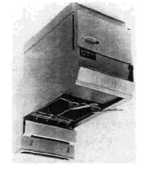
1 Installation, Operation, and Maintenance Manual For McDonald's Gas Fryer Counter Top Models 12MCD
2 NOTICES There are three different types of notices that you should be familiar with, a NOTICE, CAUTION, and WARNING. A NOTICE is a special note used to call attention to a particularly important point. CAUTION is used to point out a procedure or operation which may cause equipment damage. The WARNING notice is the most important of the three because it warns of an operation that may cause personal injury. Please familiarize yourself with your new cooker before operating it and heed the notices throughout this manual. The WARNINGS are listed below and on the following page for your review prior to operating the unit. FOR YOUR SAFETY DO NOT store or use gasoline or other flammable vapors or liquids in the vicinity of this or any other appliance. WARNING: Improper installation, adjustment, alteration, service or maintenance can cause property damage, injury or death. Read the installation, operating and maintenance thoroughly before installing or servicing this equipment TO THE PURCHASER POST IN A PROMINENT LOCATION INSTRUCTIONS TO BE FOLLOWED IN THE EVENT THAT AN OPERATOR SMELLS GAS. OBTAIN THIS INFORMATION FROM YOUR LOCAL GAS SUPPLIER. THIS MANUAL MUST BE RETAINED FOR FUTURE REFERENCE
3 SAFETY SAFETY SAFETY SAFETY SAFETY There is an open flame inside the fryer. The unit may get hot enough to set near by materials on fire. Keep the area around the fryer free from combustibles. DO NOT supply the fryer with a gas that is not indicated on the data plate. If you need to convert the fryer to another type of fuel, contact your dealer. DO NOT use an open flame to check for gas leaks! Wait 5 minutes before attempting to relight the pilot to allow for any gas in the fryer to dissipate. Never melt blocks of shortening on top of the burner tubes. This will cause a fire, and void your warranty. Water and shortening DO NOT mix. Keep liquids away from hot shortening. Dropping liquid frozen food into the hot shortening will cause violent boiling. At operating temperature the shortening temperature will be greater than 300 F. Extreme care should be exercise when working with hot shortening to avoid personnel injury. Ensure that the fryer can get enough air to keep the flame burning correctly. If the flame is starved for air it can give off a dangerous carbon monoxide gas. Carbon Monoxide is a clear odorless gas that can cause suffocation. SAFETY SAFETY SAFETY SAFETY SAFETY
4 Table of Contents Section Title Page Safety Notice Table of Contents.. List of Tables and Figures. i-ii iii Chapter I: General Information and Installation INTRODUCTION CHECKING YOUR NEW FRYER Check Your Order Heat Deflector Installation INSTALLATION Installation Clearances Gas Connection Fuel Types Fuel Supply Line Leak and Pressure Testing Gas Line Connection Ventilation and Fire Safety Systems INITIAL ADJUSTMENTS Visual Checks Burner Ignition Systems Lighting the Pilot Light Pilot Flame Adjustment Main Burner System Gas Line Requirements Burner Adjustment Initial Cleaning Thermostat Calibration Chapter 2: Operating Instructions FILLING THE FRYER Filling the Fryer With Liquid Shortening Filling the Fryer With Solid Shortening OPERATING INSTRUCTIONS Fryer Start-Up Fryer Shutdown DAILY CLEANING i
5 Table of Contents (Continued) Section Title Page CHAPTER 3: Maintenance, Adjustments, and Service WEEKLY FRYER CLEANING (BOIL OUT) FLUE AND BAFFLE INSPECTION SERVICE Replacement Procedures Main Burner Removal and Replacement Changing the Main Burner Orifice Replacing the Heat Baffles Pilot Burner Removal and Replacement Pilot Orifice Replacement Thermopile Replacement Temperature Control Board Replacement Limit Control Replacement Thermostat Probe Replacement TROUBLESHOOTING Troubleshooting Fryers With Unitrol Valves Troubleshooting Pilot Lights Troubleshooting Thermostat Systems CHAPTER 4: Parts ALPHABETICAL PART LIST NUMERICAL PART LIST ii
6 List of Tables and Figures Table Title Page 1-1 Fryer Specification Ventilation and Fire Safety References Counter Top 12 Exploded View (Index) Figure Title Page 1-2 Main Burner Conditions Gas Valve Showing Location of Pressure Regulator and Pilot Adjusters Air Collar Counter TOD 12 Exploded View iii
7 Chapter 1: General Information and Installation The frying system you have selected for your establishment has been designed by Pitco Frialator to meet the requirements of the McDonald's organization. This unit will give you many years of reliable service if you follow the simple operation and maintenance procedures in this manual. This manual contains the general installation, operation, and maintenance procedures for the McDonald's counter top models. 1.1 INTRODUCTION All models come standard with manual pilot light systems and built in safety devices. To find out which model you have. look at the identification plate inside the door. This plate has a lot of useful information, but to identify which fryer you have, look at the model number block. The model number identifies which fryer and what features you have. Table 1-1 Fryer Specifications Specification Description Domestic Units (USA) International Units (Metric) Hourly Gas Input 65,000 BTUs 16,380 KCal Number of Heat Tubes 3 3 Hourly French Fry Production 45 Lbs Kgs. Minimum Fat Capacity 30 Lbs Kgs. Frying Area 12" x 12" 30.5x30.5cm Frying Depth 3-5/8" 9.2cm Drain Valve Size 1" NPT 2.54 cm Shipping Weight 114 Lbs Kgs. Gas Connection Size 1/2" 1.27cm 1-1

8 1.2 CHECKING YOUR NEW FRYER Your new fryer has been carefully packed. Every effort has been made to ensure that your fryer will be delivered to you in perfect condition. As you unpack your new fryer, inspect each of the pieces for damage. If something is damaged, DO NOT sign the bill of lading. Contact the shipper immediately, the shipper is only responsible for 15 days after delivery. Check the packing list enclosed with your fryer to ensure that you have received all of the parts to the fryer. If you are missing any parts, contact the dealer from whom the fryer was purchased Check Your Order The crate containing the fryer unit will also contain the following: (1) Flue Heat Deflector per fryer (1) Brush (1) Fry Basket Hanger per fryer (2) Pitco Cleaner Sample (1) Drain Clean Out Rod (1) Drain Extension Heat Deflector Installation If the fryer requires a heat deflector, you will find a removable label at the rear top edge of the unit. This label has instructions for positioning and installation of the heat deflector. Refer to the label and the instructions below to install the deflector. a. Remove the two self-drilling screws from the top, back area of the cooker. b. Position the heat deflector so that the angled portion of the deflector is facing toward the front of the fryer. Secure the heat deflector to the back of the unit using the sheet metal screws previously removed. DO NOT obstruct the flow of combustion/ventilation or air openings around the fryer as this may cause the build up of dangerous gases. Adequate clearance around the fryer is necessary for servicing and proper burner operation. Ensure that you meet the minimum clearances specified in the installation instructions. c. When properly installed the angled section of the heat deflector will extend over the flue opening to redirect the heat. It SHOULD NOT cover the flue opening. Nothing should block the flue opening as this will cause the fryer to overheat and produce dangerous gases. 1-2

9 1.3 INSTALLATION The fryer must be secured to the counter top to prevent movement. Accidental movement of the fryer during operation may cause oil to splash out of the fryer. Hot oil WILL cause severe bums. Although it is possible for you to install and set up your new fryer, it is STRONGLY recommended that you have it done by qualified professionals. The professionals that install your new fryer will know the local building codes and ensure that your installation is safe Installation Clearances The fryer needs clearance around it for proper operation. Adequate clearances allow for servicing and proper burner operation. The clearances shown below are for cooker installation in combustible and noncombustible construction. Combustible Construction Non-Combustible Construction Back 6" 0" Sides 6" 0" Gas Connection Your fryer will give you peak performance when the gas supply line is of sufficient size to provide the correct gas flow. The gas line must be installed to meet the local building codes or National Fuel Gas Code (NFPA ) and ANSI Z In Canada, install the fryer in accordance with CAN-CGA 1-B 149.1,.2 and local codes. Gas line sizing requirements can be determined by your local gas company by referring to National Fuel Gas Code, Appendix C, Table C-4 (natural gas) and Table C-16 (propane). The gas line needs to be large enough to supply the necessary amount of fuel to all appliances without losing pressure to any appliance. Other factors that are used to determine the piping requirements are BTU requirements of the appliances being connected and the length of pipe between the meter and the appliances. NEVER supply the fryer with a gas that is not indicated on the data plate. Using the incorrect gas type will cause improper operation. If you need to convert the fryer to another type of fuel, contact your dealer. 1-3
10 Fuel Types - Each fryer is equipped to work with one type of fuel. The type of fuel with which the appliance is intended to operate is stamped on the data plate attached to the inside of the door. DO NOT use an open flame to check for gas leaks! Fuel Supply Line Leak and Pressure Testing - The fuel supply system must be tested before the fryer is used. If the fuel line is going to be tested at a pressure greater than (>)1/2 PSIG (3.45 kpa), make sure that the fryer is disconnected from the fuel line. If the fuel line is to be tested at a pressure equal to or less than ([) 1/2 PSIG (3.45 kpa), the fryer can be connected but the unit's gas valve must be shut. Test all gas line connections for leaks with a solution of soap and water when pressure is applied Gas Line Connection - Connect the fryer to the gas supply line with a connector that complies with the Standard for Connectors for Movable Gas Appliances (ANSI Z21.69/ CAN-CGA-6.16). NOTICE NEVER use an adaptor to make a smaller gas supply line fit the cooker connection. This may not allow proper gas flow for optimum burner operation, resulting in poor cooker performance. NEVER supply the cooker with any fuel other than the type indicated on the data plate. Using the incorrect gas type will cause improper operation. 1-4
11 1.3.3 Ventilation and Fire Safety Systems Your new fryer must have proper ventilation to function safely and properly. Exhaust gas temperatures can reach as high as 1200 F. Therefore, it is very important to install a fire safety system. Your ventilation system should be designed to allow for easy cleaning. Frequent cleaning of the ventilation system and the fryer will reduce the chances of fire. Table 1-2 provides a list of reference documents that provide guidance on ventilation and fire safety systems. This table is not necessarily complete. Additional information can be obtained from the American Gas Association, 8501 East Pleasant Valley Road, Cleveland, OH Table 1-2 Ventilation and Fire Safety References Topic Underwriters Laboratory Document National Fuel Gas Code Document Grease Extractor ANSI/UL ANSI/NFPA Ventilation Hood ANSI/UL ANSI/NFPA Filter Unit ANSI/UL ANSI/NFPA Types of Fire Extingushers and Detection Equipment ANSI/UL CO 2 ANSI/UL ANSI/NFPA Dry Chemical ANSI/UL ANSI/NFPA Water ANSI/UL ANSI/NFPA Foam ANSI/NFPA Sprinklers ANSI/UL ANSI/NFPA ANSI/NFPA Smoke Detectors ANSI/UL ANSI/NFPA 72B-1986 Fire Detection Thermostats ANSI/UL ANSI/NFPA 72B-1986 Excessive ventilation causes drafts, which will interfere with the proper operation of the pilot and the burner. Leave at least 18 inches of open space between the fryer's flue vent opening and the intake of the exhaust hood. 1-5
12 CAUTION Ensure that your ventilation system does not cause a down draft at the fryer's flue opening. Down drafts will not allow the fryer to exhaust properly and will cause overheating which may cause permanent damage. The Heat deflector DOES NOT stop down drafts. Damage caused by down drafts will not be covered under equipment warranty. NEVER allow anything to obstruct the flow of combustibles or ventilation exiting from the fryer flue. DO NOT put anything on top of the flue area. NOTICE NEVER connect the blower directly to the flue openings. The direct flow of air will cause poor temperature recovery, poor ignition, inefficient operation of the fryer, and could extinguish the pilot. 1.4 INITIAL ADJUSTMENTS After your fryer has been installed as described in section 1.3, it needs to be adjusted to ensure that it will perform as designed. These adjustments must be performed by a qualified person. To perform these adjustment the following tools will be needed: Manometer (low pressure gage) DC Millivolt Meter Digital Thermometer (Temperature probe) Visual Checks Before you begin filling and adjusting the fryer, perform the following visual checks: a. After the fryer is in its permanent location, check the levelness. Any additional leveling that is necessary must be performed before using the fryer b. Check the temperature bulbs (thermostat/high-limit), located in the fryer tank to ensure that the mounting screws are tight. The figure shows the probe location. Look down inside the fryer tank to see the probes. 1-6


13 1.4.2 Burner Ignition Systems The counter top fryer has a standing manual pilot system. Follow the procedures in this section to light and adjust the pilot system. CAUTION Before going any further, fill the fryer with WATER. Water is used for the installation adjustments because the temperature will never exceed 212 F (100 C) thereby allowing plenty of adjustment time. Never let the water level go below the MIN LEVEL mark on the rear of the tank. There is an open flame inside the fryer. The unit may get hot enough to set near by materials on fire. Keep the area around the fryer free from combustibles Lighting the Pilot Light Wait 5 minutes before attempting to relight the pilot to allow for any gas in the fryer to dissipate. a. Open the gas supply valves to the fryer. b. Open the fryer's door to gain access to the controls. Ensure that the thermostat control knob is in the OFF position. c. Turn the Unitrol valve knob to the PILOT position and push in on the knob. Hold the knob in for approximately one minute to purge the air from the line. Hold a flame to the pilot burner until the pilot ignites. This may take a little while the first time you light the fryer because of air in the lines. Once lit, hold the knob in for approximately 60 seconds then release. The air only needs to be purged from the line the first time the pilot is lit or after the gas line has been disconnected. d. If the pilot goes out wait 5 minutes and repeat step c. If after three tries the pilot will not remain lit, refer to the operator troubleshooting section of this manual. e. Turn the Unitrol gas valve knob counterclockwise to the ON position. f. Turn the fryer thermostat knob to the desired temperature. 1-7
14 g. The main burner will light and be controlled by the thermostat. The pilot burner will remain lit regardless of the thermostat setting Pilot Flame Adjustment - The pilot flame should be adjusted to produce the proper millivolt output from the pilot sensing device. There are two types of pilot sensing devices thermopile or thermocouple. Millivolt output for the thermopile should be between 300 and 500 millivolts. Figure 1-1 shows the pilot assembly with examples of the incorrect and correct pilot size. Example A illustrates a pilot flame size that is too small to produce sufficient millivolt output. Example B is the correct size for proper millivolt output. Figure 1-1 Pilot Assembly, Flame Adjustment a. This test requires a DC millivolt meter set to a scale of 0-l000mv. b. Locate the thermopile wires at the Hi-limit. c. Using the positive (+) test probe, touch the probe to one of the High Limit wire terminals. d. Connect the negative (-) test probe to pilot bracket. If the reading on the meter, when the pilot is lit, is 400 ± 50mv the pilot flame does not need adjustment. If the voltage is not correct proceed to step e. e. Remove the pilot flame adjustment cover. f. Turning the flame adjusting screw (figure 1-3) clockwise lowers the flame and the millivolt output. Turning the screw counterclockwise increases flame size and millivolt output. g. Rotate the screw in the direction to achieve a reading of 400 ±50 mv for thermopiles. NOTICE Allow 3 to 5 minutes between flame adjustments to allow the reading to settle. h. Replace the pilot flame adjusting screw cover. 1-8

15 1.4.3 Main Burner System The main burner receives gas from the main gas supply through the thermostatically controlled valve. When the thermostat is turned up the gas control valve opens. After the burner system is operating, perform the burner adjustments in the following procedure. Figure 1-2 illustrates the different conditions possible for the main burner. The tubes and baffles are badly carbonized. Check vent and adjust if necessary. Check for heat tube or flue blockage. The flame seems to "lift off the face of the burner. To correct adjust main burner as described in INSUFFICIENT FLOW EXCESSIVE FLOW Have gas company check incoming gas pressure. Adjust manifold pressure as described in A soft, steady blue flame should enter the heat tube without touching the front outside rim of the tube. INSUFFICIENT GAS PRESSURE NORMAL FLOW Figure 1-2 Main Burner Conditions 1-9
16 Gas Line Requirements - A properly installed gas supply system will deliver 5.0" - 6.0" w.c. natural gas (11.0" " w.c. LP) to all appliances connected to the line, operating at full demand Burner Adjustment - The burners must be adjusted to deliver optimum flame. Adjust the burner flame using the following procedure. a. Ensure that the main gas valve is shut off, remove the manifold pressure tap plug and connect an accurate pressure gage (range of 0-16" w.c. in 0.1" increments) or manometer. Figure 1-3 Gas Valve Showing Location of Pressure Regulator and Pilot Adjusters b. Turn on all appliances connected to the gas supply line and light their main burners. The pressure reading of the installed pressure gage should not drop from the required installation pressure. Any loss of pressure indicates inadequate supply line installation which will cause poor performance of all appliances during peak usage. c. The installed pressure gage reading should be the same, ±0.1", as that marked on the data plate inside the door. If the pressure is correct go to step f, if not, adjust the pressure. d. To adjust the pressure, remove the regulator adjustment screw cover (see Figure 1-3). Use a flat tip screwdriver to adjust the screw until the proper pressure is reached. Turning the screw clockwise will increase the pressure, counterclockwise will decrease the pressure. e. When the pressure is correct, install the regulator adjustment screw cover. f. To remove the pressure gage, turn off fryer and shut the main gas valve. Remove the gage 1-10
17 and install the pressure tap plug using some pipe sealing compound. Figure 1-4 Air Collar g. Now that the pressure is set for proper operation, set the main burner flame. Unlock the air collars by loosening the set screw for the collars. Open the main gas valve, light the pilot, and turn thermostat to light the main burners. h. Adjust the shape and size by raising or lowering the air collars to achieve a soft blue flame with well defined inner cones as seen on figure 1-2. i. When the flames have been properly adjusted, lock the collars in place with the set screw provided Initial Cleaning When the fryer is shipped, many of its parts are covered with a thin coat of cooking oil for protection. Before the fryer is ready for cooking it must be cleaned. This will remove the oil coating and any foreign matter that may have accumulated during storage and shipment. Perform the cleaning as described below. During cleaning a. Fill the fryer with water. Turn the fryer on and set the thermostat to 200 F. b. Allow the fryer to heat for 15 minutes. Add Pitco fryer cleaner directly to the water, stirring with the fryer cleaning brush to ensure cleaner has dissolved thoroughly. NOTICE Do not leave the fryer unattended during cleaning. Never let the water level go below the "Min Level" mark on the back of the tank. 1-11
18 c. Using the fryer cleaning brush, scrub the inside of the fryer to remove protective coating. d. When cleaning is complete, turn the thermostat to OFF and turn gas valve knob to the Pilot position. Drain the water into a container suitable for hot water and dispose of it. e. When the tank has cooled, rinse it thoroughly with cool water. Continue to rinse the tank until the cleaner has been rinsed, thoroughly from the tank. f. Using a clean dry cloth, wipe out all of the water. Be very thorough removing the water, because any residual water will cause hot oil to splatter out of the fryer. CAUTION Mild steel tanks must be wiped down/coated with oil to keep the tank from rusting. g. Now that the tank is clean, you are ready to fill and operate the fryer. Refer to 2.1 for instructions on adding shortening to the fryer Thermostat Calibration Filling the fryer with oil is described in 2.1. To perform the calibration check detailed below you will need a digital thermometer. NOTE The thermostat calibration should be checked only. If the setting is off a few degrees perform the steps that follow. If the dial setting is off a significant amount call a qualified technician for warranty service. a. Place the tip of the thermometer in the shortening approximately 1" above the temperature sensors. b. Set the thermostat at 325 F and wait for the temperature reading on the thermometer to rise. As the temperature rises toward 325 F watch the thermometer closely. c. If the shortening temperature reaches 350 F and the burners DO NOT turn off, turn the thermostat down. Keep lowering the thermostat setting until the burners go out. CAUTION If the burners do not turn off at the lowest thermostat setting, the thermostat could be defective. Contact your ASAP representative. 1-12
19 d. Let the fryer cycle 4 to 6 times before checking the temperature. Compare the thermometer temperature against the thermostat setting. If the values are more than 5 F apart continue with calibration, if they are not go to i. e. Loosen the set screw that holds the thermostat knob to its shaft. f. Rotate the thermostat dial without moving the shaft to the temperature indicated on the thermometer. Tighten the set screw on the thermostat dial to lock the dial on place. g. Adjust the thermostat to a new setting and allow the fryer to cycle 4 to 6 times at the new temperature. Check the thermometer temperature against the thermostat dial, if it greater than 5 F away from the dial setting, perform the above procedure again. If the temperature is ±5 F of the thermostat dial setting, the thermostat is set correctly. h. When the calibration is correct, remove the thermometer and replace the tube screen. 1-13

20 Chapter 2: Operating Instructions This chapter describes how to operate your fryer to obtain the best performance. Included in this chapter are filling, operating, and cleaning instructions for gas fryers. 2.1 FILLING THE FRYER Both liquid and solid shortening can be used in the fryer, but liquid is preferred. You can melt solid shortening but you must carefully follow the instruction in section Filling the Fryer With Liquid Shortening a. Make sure the drain valve is completely closed. b. Fill the fryer with oil to the "Oil Level" line marked on the back of the kettle Filling the Fryer With Solid Shortening Never melt blocks of solid shortening on top of the burner tubes. This will cause a fire, and will void your warranty. a. Make sure the drain valve is completely closed. b. Remove the screen covering the tubes. c. Cut the shortening into cubes no larger than 1". ALWAYS pack the shortening below, between, and on top of the burner tubes. DO NOT leave any large air gaps. Use care when packing the solid shortening in the kettle. DO NOT bend or break the temperature sensor probes. If these are damaged the fryer will not function properly. c. Once the fryer is packed with shortening, the shortening must be melted. Place the switch, located above the thermostat knob, in the MELT ON position. The fryer will automatically melt the shortening using short, controlled, bursts of heat. The melt cycle will continue until cooking temperature has been reached. 2-1

 to the desired temperature setting.")
21 2.2 OPERATING INSTRUCTIONS To ensure the food always comes out the very best, follow the preparation instructions for the food you are cooking. Using the best shortening makes the best fried foods. The best shortening will last longer than lower grade shortening and save you money. When not in use the shortening should be cooled and covered to prevent contamination Fryer Start-Up Water and shortening DO NOT mix. Keep liquids away from hot shortening. Dropping liquid frozen food into the hot shortening will cause violent boiling. DO NOT START FRYER WITHOUT FILLING WITH OIL! a. Light the pilot light as described in section b. Turn the temperature control knob (thermostat) to the desired temperature setting. This knob is located behind the front doors or on the front control panel. c. Turn the fryer ON by pressing the ON side of the ON/OFF/TEST switch. The POWER ON light and the HEATING light will come on. The HEATING light cycles with the main burners. d. Place the melt option switch in the MELT ON position. If the oil temperature is less than 150 F, the burners will turn on for 4 seconds and remain off for 30 seconds. This will heat the shortening slowly to 150 F (65 C). At 150 F (65 C) the burners will remain on constantly until the shortening reaches the thermostat setting. e. The Melt Cycle switch can be left ON after reaching normal temperature. The fryer is now at normal operating temperature and ready for use Fryer Shut-Down There are two shutdown modes of fryer operation, STANDBY and COMPLETE. The standby mode removes the ability for the fryer's main burners to cycle. Complete shutdown turns off the gas supply to the fryer. Shut down the fryer by: STANDBY Turn the thermostat to OFF. Depress and turn the gas valve clockwise to the PILOT position. The cooker is now in Standby and can remain this way for only brief periods of time. NEVER leave the cooker in standby overnight. 2-2
22 COMPLETE To completely shut down the cooker, turn the gas valve counter clockwise to the OFF position and turn the power switch OFF. The fryer is now completely shut down and can be cleaned. 2.3 DAILY CLEANING Your fryer should be cleaned every day to maintain peak performance and appearance. Perform the procedures below every day. a. Wipe up any shortening that spills onto the exterior of the fryer. This should be done with a clean soft cloth while the oil is still warm. b. Use warm water with a mild detergent to clean surfaces. Be careful not to get water in the shortening and to remove any detergent from the fry tank. c. Use a non-abrasive scouring powder or pad to clean stains if necessary. d. Perform the weekly boil out cleaning of your fryer described in section

23 Chapter 3: Maintenance, Adjustments, and Service This chapter provides you with the information and procedures necessary to perform basic fryer maintenance and adjustments. If after performing maintenance on your fryer it does not perform properly, contact your authorized service center. 3.1 WEEKLY FRYER CLEANING (BOIL OUT) The fryer should be thoroughly cleaned once a week. This cleaning should include a complete draining of the fryer and a boil out. a. You will need a container large enough to hold 1-1/2 times the oil in one tank. This container should also be able to withstand temperatures in excess of 350 F (177 C). CAUTION Completely shut down the fryer before draining the oil and replacing with water. If possible, allow the oil to cool to less than 130 F (54.4 C). At operating temperatures, the shortening in the fryer may be hotter than 375 F (190 C). This hot, melted shortening can cause severe bums. Do not let hot shortening touch your skin or clothing. Always wear insulated oil-proof gloves and eye protection when working with hot oil b. Drain the oil from the fryer and discard or save for reuse. Remove the tube screens. Close the drain valve and fill the tank with warm water and non-caustic detergent. For best results use Pitco Fryer Cleaner part number P (sample packet included with the fryer). c. Restart your fryer as described in 2.2 and set the thermostat to 200 F and bring the water to a slow boil. DO NOT allow water to boil because excessive foaming will occur. d. Allow the fryer to soak for 20 minutes to soften shortening deposits. Use fryer brush to remove any residue from tank, tubes, and side walls. Perform the daily cleaning procedure described in section 2.3. e. Drain the hot water into a container and dispose of the oil in an ecologically sound manner. Rinse the tank with clean warm water. f. Wipe the tank dry with clean cloth wipes taking care to remove ALL of the water. Close the drain valve and remove the large container. g. Replace the tube screens and refer to section 2.1 to refill the fryer. 3-1

24 3.2 FLUE AND BAFFLE INSPECTION It is recommended that once every six months with the cooker cooled down you examine the flue area and the burner tube baffles. Check for corrosion or blockage of the flue and erosion of the baffles. Ensure that the cooker is shutdown and cooled to room temperature. Do not turn it on during the examination. Examination of the flue area during cooking may cause bodily injury. 3.3 SERVICE This section is provided to aid you in the event of fryer or filter troubles. If these troubleshooting procedures do not correct your problem contact a qualified technician or the factory. The troubleshooting procedures are in a flowchart format Replacement Procedures These procedures are provided to the qualified technician as a guide to removal and replacement of various fryer components. If a test is required to verify component operation after installation, it will be referenced. To prevent bums, always ensure the fryer is completely SHUT DOWN and COOLED down before working on the fryer. Do not break any fryer gas connections while the unit is connected to a gas supply line Main Burner Removal and Replacement a. Loosen the set screw in the base of the burner casing. b. Unscrew and remove the two hex head screws at the top of the burner. c. Loosen the set screw. Lift the burner and air collar up to clear the top of the burner fitting. Remove the burner from the fryer. d. To reinstall the burner, reverse the procedure Changing the Main Burner Orifice a. Unscrew the orifice with a 3/8" wrench and remove the orifice. d. Insert the new orifice and tighten with the 3/8" wrench. Ensure the orifice is tight enough to prevent gas leakage around the orifice. 3-2
25 Replacing the Heat Baffles a. Remove the Main Burner as described in b. The heat baffles are located inside the heat tubes. They are attached to the rear of the baffle supported by tack welds. Using a chisel, break away the baffle support and remove the old baffles. Be careful not to puncture the heat tubes because this will require complete tank replacement. c. Insert the new baffles in the tubes in the original position. d. Install the main burners Pilot Burner Removal and Replacement a. Unscrew the tubing nut from the pilot tubing connection at the gas valve. Disconnect the thermopile from the connection on the gas valve. b. Unscrew and remove the two screws that attach the pilot assembly to the fryer tank. Lift the entire pilot assembly out of the fryer. c. To replace the pilot assembly, reverse the procedure Pilot Orifice Replacement a. Remove the pilot assembly as described in b. Unscrew the tubing nut from the pilot tubing connection at base of the pilot burner. The pilot orifice is located inside the tubing connection. c. Remove the orifice and replace with the new orifice. Ensure the orifice is tight enough to-prevent gas leakage around the orifice. d. Replace the tubing in the pilot tubing connection and tighten the tubing nut tight enough to prevent gas leakage. e. Replace the pilot assembly and adjust the pilot flame as described in Thermopile Replacement a. Remove the pilot assembly as described in b. Unscrew and remove the thermopile from the pilot assembly. c. Unscrew the thermopile from the gas valve magnet. 3-3
26 d. Screw the new thermopile into the pilot assembly and the gas valve magnet. e. Replace the pilot assembly and adjust the pilot flame as described in f. Ensure that all nuts and screws are tight Temperature Control Board Replacement a. Disconnect the power from the fryer. b. Shut the gas supply valve to the fryer. c. Turn the unit 180 so that the back of the fryer is toward you. d. Remove the four hex head slotted screws from the entrance box at the bottom of the unit. Remove the box and set it down gently. e. Disconnect the white nine socket jack and the four socket jack. The box should now be free. f. Disconnect all 11 spade terminations from the temperature control board. g. Remove the two hex nuts fastening the board to the box. Remove the defective board and discard. h. Install the new temperature control board by refastening the hex nuts and reconnecting the spade termination. Refer to the schematic for the proper connection. i. Reconnect the white nine socket jack and the four socket jack. Refasten the entire box to the fryer High Limit Control Replacement - The High Limit control includes a temperature sensor inside the fryer tank, control unit inside the fryer cabinet, and connecting capillary tubing. CAUTION The High Limit control capillary tubing is very delicate. Be VERY CAREFUL when working with the capillary tubing. If the tubing is kinked or broken the High Limit control is no longer usable. a. Drain the oil from the fryer and remove the heat tube screens. b. The High Limit control probe (heat sensor) is clamped to the right hand heat tube inside the tank. Unscrew and remove the two screws in the probe clamp. 3-4
27 c. Remove the probe from the clamp and gently straighten the capillary tubing. Unscrew the small hex nut inside the cabinet at the bottom of the tank for the High Limit control. Make sure the capillary tube is free. d. Unscrew the large connector nut from the tank and pull the probe and capillary tubes through the opening. e. Remove the two mounting screws from the High Limit control bracket and remove the High Limit control unit. Disconnect the wires from the High Limit body. f. Reverse the procedure to install the new High Limit control. g. Use pipe joint compound on the large fitting before installing to prevent oil leakage. DO NOT use joint compound on the small nut Thermostat Probe Replacement a. Drain the oil from the fryer and remove the heat tube screen. The thermostat probe (heat sensor) is clamped to the left hand heat tube inside the tank. Unscrew and remove the two screws in the thermostat probe clamp. b. Remove the thermostat probe from the clamp. Unscrew the small hex nut inside the cabinet under the tank for the thermostat control. c. Unscrew the large connector nut from the tank and pull the thermostat probe through the opening. d. Unplug the electrical connection. e. Install the new thermostat in reverse order. f. Use pipe joint compound on the large fitting before installing to prevent oil leakage. DO NOT use joint compound on the small nut. g. Perform the calibration procedures detailed in section
28 3.4 TROUBLESHOOTING This section is provided to aid you in the event of fryer troubles. If these troubleshooting procedures do not correct the problem contact a qualified technician or the factory. The troubleshooting procedures are in flowchart format Troubleshooting Fryers With Unitrol Valves 3-6
29 3-7
30 3.4.2 Troubleshooting Pilot Lights 3-8
31 3.4.3 Troubleshooting Thermostat System 3-9
32 Chapter 4: Parts This chapter contains listings of the components used in the different models of McDonald's fryer. These components are listed in two places, with the illustration and in ordered part lists. The illustrations in this chapter are provided to show relative location of component of the fryer. With each illustration there is a table of components in numerical order by illustration number. The illustration has numbered lines pointing to components which are listed in the table. At the end of this chapter there are alphabetical and numerical listings of all parts used in the fryer. The alphabetical part list is arranged in alphabetical order according to the part name. Each part name also has the Pitco Frialator part number. The numerical list is in Pitco Frialator part number order. A brief description of each component is provided for each part. 4-1
33 Figure 4-1 Counter Top 12 Exploded View 4-2
34 Table 4-1 Counter Top 12 Exploded View (Index) Index Number Description Index Number Description 1 Cabinet, Weldment 8 Door Assembly 12 MCD 2 Tank Weldment SS 8A Handle, Chrome 2A Baffle, Removable 6,12 8B Plug, Hole 1/2" Chrome 3 Flue Weldment 9 Probe, Thermistor Gas 4 Front Panel 12A Gas 10 Piping, Pilot 12C Nat 5 Entrance Box, Assembly 10A Thermopile CP2 24" 5A Control, Temperature 24 VAC GO On-8, Off Switch, Hi Limit 5B Transformer, 40 VA 120/208/240 to Burner, Pitco 4" 6 Auxiliary Box, Assembly 13 Valve, Ball 1" Plated 6A Fuse, 1 Amp Slow Blow Glass 14 Piping Collar Air 6B Potentiometer, ohm 15 Top Door Hinge 6C Switch, Toggle (ON-OFF-ON) DPDT 16 Hinge, Door Bottom Weldment 6D Knob, Thermostat McDonald's 17 Cabinet, Bracket Magnet Catch 7 Piping, Supply Gas 12C Nat 18 Magnet 7A Valve, Gas 1/2" Thermopile Nat 19 Cabinet, Bracket Magnet Catch 7B Orifice #45 20 Hanger, Basket 12 SS * For complete part information, refer to the part lists later in this chapter. 4-3
35 AIR COLLAR AUXILIARY BOX, ASSEMBLY BAFFLE, REMOVABLE 6,12 BURNER, PITCO 4" CABINET, BRACKET MAGNET CATCH CABINET, BRACKET MAGNET CATCH CABINET, WELDMENT ALPHABETICAL PART LIST Part Description CONTROL, TEMPERATURE 24 VAC GO ON-8, OFF-22 DOOR ASSEMBLY 12 MCD ENTRANCE BOX, ASSEMBLY FLUE WELDMENT FRONT PANEL 12A GAS FUSE, 2 AMP SLOW BLOW GLASS FUSE HOLDER HANDLE, CHROME Pitco Frialator Part Number A B B P A A B PP10561 B B B B P P P HANGER, BASKET 12 SS A HINGE, DOOR BOTTOM WELDMENT KNOB, THERMOSTAT MCDONALD'S MAGNET ORIFICE #45 PIPING, PILOT 12C NAT PIPING, SUPPLY GAS 12C NAT PLUG, HOLE 1/2" CHROME POTENTIOMETER, OHM PROBE, THERMISTOR GAS SWITCH, HI LIMIT SWITCH, TOGGLE (ON-OFF-ON) DPDT TANK WELDMENT SS THERMOPILE CP2 24" TRANSFORMER, 40 VA 120/208/240 TO 24 VALVE, BALL 1" PLATED VALVE, GAS 1/2" THERMOPILE NAT VALVE, GAS 1/2" THERMOPILE LP B P P P B B P P B PP10084 P B P PP10210 P P P
36 NUMERICAL PART LIST Pitco Frialator Part Number A A Al A HANGER, BASKET 12 SS CABINET, BRACKET MAGNET CATCH CABINET, BRACKET MAGNET CATCH AIR COLLAR B BAFFLE, REMOVABLE 6,12 B B B B B B B B B B B P P P P P P CABINET, WELDMENT DOOR ASSEMBLY 12 MCD ENTRANCE BOX, ASSEMBLY TANK WELDMENT SS FLUE WELDMENT HINGE, DOOR BOTTOM WELDMENT AUXILIARY BOX, ASSEMBLY PROBE, THERMISTOR GAS FRONT PANEL 12A GAS PIPING, PILOT 12C NAT PIPING, SUPPLY GAS 12C NAT VALVE, GAS 1/2" THERMOPILE NAT VALVE, GAS 1/2" THERMOPILE LP FUSE, 2 AMP SLOW BLOW GLASS FUSE HOLDER POTENTIOMETER, OHM SWITCH, TOGGLE (ON-OFF-ON) DPDT P THERMOPILE CP2 24" P BURNER, PITCO 4" P P KNOB, THERMOSTAT MCDONALD'S MAGNET P ORIFICE #45 P P P PP10084 PLUG, HOLE 1/2" CHROME HANDLE, CHROME VALVE, BALL 1" PLATED SWITCH, HI LIMIT PP10210 TRANSFORMER, 40 VA 120/208/240 TO 24 PP10561 Part Description CONTROL, TEMPERATURE 24 VAC GO ON-8, OFF
Installation and Operation Manual Covering Model 40S, 40C, 40D with Millivolt Gas Valve
 IMPORTANT FOR FUTURE REFERENCE Please complete this information and retain this manual for the life of the equipment: Model #: Serial #: Date Purchased: ENGLISH Installation and Operation Manual Covering
Installation and Operation Manual Covering Model 35C+, 45C+ with Millivolt Gas Valve
 IMPORTANT FOR FUTURE REFERENCE Please complete this information and retain this manual for the life of the equipment: Model #: Serial #: Date Purchased: ENGLISH Installation and Operation Manual Covering
GPC PASTA PRO INSTALLATION & USER OPERATION MANUAL
 GPC-14/18/20 GPC PASTA PRO INSTALLATION & USER OPERATION MANUAL GPC-18 shown with optional rinse station. NOTICE! After installation of your equipment, immediately contact your local gas supplier to obtain
Owner s Guide Installation & Operation
 Owner s Guide Installation & Operation Fryer HFR Series Hestan Commercial Corporation 3375 E. La Palma Ave Anaheim, CA 92806 (888) 905-7463 RETAIN THIS MANUAL FOR FUTURE REFERENCE P/N 002137 REV 1 IMPORTANT
Installation, Operation, and Maintenance Manual RTE14S & RTE14S-2. For the Taco Bell "Rethermalizer" Model Numbers
 Installation, Operation, and Maintenance Manual For the Taco Bell "Rethermalizer" Model Numbers RTE14S & RTE14S-2 NOTICES There are three different types of notices that you should be familiar with, a
OWNERS MANUAL INSTALLATION, OPERATION, & MAINTENANCE INSTRUCTIONS
 OWNERS MANUAL INSTALLATION, OPERATION, & MAINTENANCE INSTRUCTIONS 1128 Sherborn Street Corona, CA 92879-2089 (951) 281-1830 (951) 281-1879 IPC SERIES PASTA COOKER All Imperial Mfg. Co. equipment is manufactured
PLEASE RETAIN THIS MANUAL FOR FUTURE REFERENCES. This equipment is design engineered for commercial use only
 OWNER S MANUAL INSTALLATION OPERATION MAINTENANCE FRYER SRF-40/50 All equipment manufactured by SIERRA CORP. is for use with the type of gas specified on the rating plate and for installation will be in
INSTALLATION & OPERATION MANUAL
 INSTALLATION & OPERATION MANUAL EF SERIES ECONOFRY GAS FRYERS MODEL EF3 EF4 EF5 ML-52099 ML-114943 ML-114944 MODEL EF3 For additional information on Vulcan-Hart or to locate an authorized parts and service
Owner s Guide Installation & Operation
 Owner s Guide Installation & Operation Hot Top HHT Series Hestan Commercial Corporation 3375 E. La Palma Ave Anaheim, CA 92806 (888) 905-7463 RETAIN THIS MANUAL FOR FUTURE REFERENCE P/N 002130 REV 1 IMPORTANT
Owner s Guide Installation & Operation
 Owner s Guide Installation & Operation Char Broiler HCH Series Hestan Commercial Corporation 3375 E. La Palma Ave Anaheim, CA 92806 (888) 905-7463 RETAIN THIS MANUAL FOR FUTURE REFERENCE P/N 002134 REV
PRO SERIES GAS FRYERS OWNER S MANUAL
 PRO SERIES GAS FRYERS OWNER S MANUAL MODELS: PF-1 PRO-FRYER, PF2 DUAL PRO-FRYER REVISED OCTOBER, 2009 *PLEASE RETAIN FOR FUTURE REFERENCE This appliance has been tested according to ANSI Z83.116-2009/CSA1.86-2009.
CINCINNATI, OH USA
 INSTRUCTION MANUAL Part No. 89731 Revised October 1997 CINCINNATI, OH 45241-4807 USA GAS SAFETY PRECAUTIONS Instructions on what to do when a user smells gas can be obtained from the local gas supplier.
INSTALLATION AND OPERATION MANUAL GAS SKILLETS MODELS: GTS-30 GTS-40
 INSTALLATION AND OPERATION MANUAL GAS SKILLETS MODELS: GTS-30 GTS-40 CROWN FOOD SERVICE EQUIPMENT LTD. 70 OAKDALE ROAD, DOWNSVIEW, (TORONTO), ONTARIO, CANADA, M3N 1V9 TELEPHONE: (416) 746-2358, FAX: (416)
Gas Countertop Fryer lb Model lb Model NG and LPG Models
 Gas Countertop Fryer 35-40 lb Model 45-50 lb Model NG and LPG Models This manual contains important information regarding your unit. Please read this manual thoroughly prior to equipment set-up, operation
Service Manual For model N260 - a 2.4 cu. ft., 2-way refrigerator. For model N a 2.4 cu. ft., 3-way refrigerator.
 Service Manual For model N260 - a 2.4 cu. ft., 2-way refrigerator. For model N260.3 - a 2.4 cu. ft., 3-way refrigerator. NORCOLD, Inc. P.O. Box 4248 Sidney, OH 45365-4248 Part No. 619260A (4-98) Table
STAR-MAX GAS GRIDDLES MODELS 615MA 624MA 636MA 648MA 615TA 624TA 636TA 648TA 624TSPA 636TSPA 648TSPA
 Star Manufacturing International Inc. 10 Sunnen Drive St. Louis, MO 63143 Phone: (314) 781-2777 Fax: (314) 781-3636 Installation and Operating Instructions 2M-Z1351 Rev. B 4/23/04 STAR-MAX GAS GRIDDLES
STAR-MAX PROPANE GAS GRIDDLE
 Star Manufacturing International Inc. 10 Sunnen Drive St. Louis, MO 63143 Phone: (314) 781-2777 Fax: (314) 781-3636 Installation and Operating Instructions 2M-Z3793 Rev. B 3/28/03 STAR-MAX PROPANE GAS
V SERIES HDR GAS RANGES
 SERVICE MANUAL ONE POWERFUL PACKAGE V SERIES HDR GAS RANGES TOPS Open Top Hot Top Griddle Top Work Surface BASES Standard Oven Convection Oven Cabinet Base - NOTICE - This manual is prepared for use by
INSTALLATION & OPERATIONAL MANUAL
 INSTALLATION & OPERATIONAL MANUAL LG SERIES GAS FRYERS MODELS: LG300 LG400 LG500 ML-136528 ML-136622 ML-136643 For additional information on Vulcan-Hart or to locate an authorized parts and service provider
ULTRA-MAX GAS RADIANT CHARBROILER. ULTRA-MAX GAS LAVA ROCK CHARBROILER MODELS 8024CBB, 8036CBB, 8048CBB, 8060CBB, and 8072CBB
 Star Manufacturing International Inc. 10 Sunnen Drive St. Louis, MO 63143 Phone: (314) 678-6303 Fax: (314) 781-2714 Installation and Operating Instructions 2M-Z20327 Rev. A 10/05/15 ULTRA-MAX GAS RADIANT
TRI-STAR INC SOUTH STANDARD AVENUE, SANTA ANA, CA Ph: Fax: MODEL #. OWNER S MANUAL
 TRI-STAR INC 2205 SOUTH STANDARD AVENUE, SANTA ANA, CA 92707 Ph: 714 424 9380 Fax: 714 424 9385 MODEL #. OWNER S MANUAL INSTALLATION OPERATION MAINTENANCE All equipments manufactured by Tri-star Inc. for
User Manual. 110 Cup (55 Cup Raw) Gas Rice Cooker. Model: 177GRCLP, 177GRCNAT 12/2018. Please read and keep these instructions. Indoor use only.
 Gas Rice Cooker. Model: 177GRCLP, 177GRCNAT 12/2018. Please read and keep these instructions. Indoor use only.") 110 Cup (55 Cup Raw) Gas Rice Cooker Intertek 5010781 Conforms to ANSI STD Z83.11-2016 Model: 177GRCLP, 177GRCNAT 12/2018 FOR YOUR SAFETY Do not store or use gasoline or other flammable vapors or liquids
110 Cup (55 Cup Raw) Gas Rice Cooker Intertek 5010781 Conforms to ANSI STD Z83.11-2016 Model: 177GRCLP, 177GRCNAT 12/2018 FOR YOUR SAFETY Do not store or use gasoline or other flammable vapors or liquids
INSTALLATION, OPERATION & MAINTENANCE AVANTCO SERIES 177AG OWNER S MANUAL
 INSTALLATION, OPERATION & MAINTENANCE AVANTCO SERIES 177AG OWNER S MANUAL Manual Griddles: Radiant Charbroilers: Hot Plates: 177AG24MG 177AG36MG 177AG24RC 177AG36RC 177AGR212 All equipment manufactured
SR42G/52G Series Gas Fryers
 SR42G/52G Series Gas Fryers Installation & Operation Manual PRINTED IN THE UNITED STATES For Service, Call (318) 865-1711 Dean, 8700 Line Avenue, PO Box 51000, Shreveport, Louisiana 71135-1000 Shipping
Gas Cooktop Installation, User and Service Instructions GMS 955.1
 Gas Cooktop Installation, User and Service Instructions GMS 955.1 IMPORTANT: SAVE FOR LOCAL ELECTRICAL INSPECTOR S USE. READ AND SAVE THESE INSTRUCTIONS FOR FUTURE REFERENCE. OBSERVE ALL FEDERAL, STATE
Stone Hearth Pizza Dome Oven
 Stone Hearth Pizza Dome Oven INSTALLATION AND OPERATION MANUAL GAS-FIRED OVEN CAUTION This oven MUST be seasoned before initial use The seasoning procedure takes 6 days, running the oven for at least 8
MODELS: JGM, JGGM, JGT, JGTS, JGTSD, JGTSDS, JGGT, JGGTS, JTYG GRIDDLES AND JHP, JHPE HOT PLATES
 Jade Range LLC, A Middleby Company 2650 Orbiter Ave. Brea, CA 92821 Telephone (714) 961-2400 FAX (714) 961-2550 MODELS: JGM, JGGM, JGT, JGTS, JGTSD, JGTSDS, JGGT, JGGTS, JTYG GRIDDLES AND JHP, JHPE HOT
Service Manual Model 3163
 Service Manual Model 3163 Contents Important Safety Information.......... 1 Specifications.................. 2 General Information.............. 2 Direct Vent Requirements........... 2 Propane System................
CYLINDER NOT INCLUDED
 OPERATING INSTRUCTIONS AND OWNER S MANUAL Model # HS125NG / MH125LP / HS125LP READ INSTRUCTIONS CAREFULLY: Read and follow all instructions. Place instructions in a safe place for future reference. Do
INSTALLATION & OPERATION MANUAL GAS CHARBROILERS
 INSTALLATION & OPERATION MANUAL GAS CHARBROILERS MODELS VCCB25 VCCB36 VCCB47 VCCB60 VCCB72 VCCB47 SCB25 SCB36 SCB47 SCB60 SCB72 SCB47 ITW Food Equipment Group, LLC 3600 North Point Blvd. Baltimore, MD
21 20 LITER GAS FRYER FFA3200 INSTALLATION AND SERVICING.
 21 20 LITER GAS FRYER FFA3200 INSTALLATION AND SERVICING www.anvilworld.com 20 ALL ANVIL EQUIPMENT COMES WITH A ONE YEAR WARRANTY ON COMPONENTS AND DEFECTIVE WORKMANSHIP. www.anvilworld.com 19 20 LITER
Apollo Series Fryers
 INSTALLATION & OPERATION MANUAL Apollo Series Fryers ModelA-3-NAT A-3-LP (3 Burners Fryer) Model A-4-NAT A-4-LP (4 Burners Fryer) Model A-5-NAT A-5-LP ( 5 Burners Fryer) WARNING: IMPROPER INSTALLATION,
OPERATING INSTRUCTIONS AND OWNER S MANUAL
 OPERATING INSTRUCTIONS AND OWNER S MANUAL MR. HEATER READ INSTRUCTIONS CAREFULLY: Read and follow all instructions. Place instructions in a safe place for future reference. Do not allow anyone who has
LP GAS PIZZA OVEN USER MANUAL
 LP GAS PIZZA OVEN USER MANUAL To reduce the risk of fire, burn hazard or other injury, read the USER MANUAL carefully and completely before using this appliance FOR OUTDOOR USE ONLY Before Cleaning, make
FRYMASTER TCF. Chicken Fryer
 Hardee s Food Systems, Inc. FRYMASTER TCF Chicken Fryer EQUIP 501 Chicken Fryer October 1, 1994 CALIBRATION EQUIPMENT and TOOLS Digital Thermometer Flat Blade or Phillips w/immersion Probe Screwdriver
Installation Manual. For Australian refrigerator models: N304M.3 (93 liter 3-way operation with LP gas, 240 volts AC, or 12 volts DC )
") Installation Manual For Australian refrigerator models: N304M.3 (93 liter 3-way operation with LP gas, 240 volts AC, or 12 volts DC ) N404M.3 (128 liter 3-way operation with LP gas, 240 volts AC, or 12
Installation Manual For Australian refrigerator models: N304M.3 (93 liter 3-way operation with LP gas, 240 volts AC, or 12 volts DC ) N404M.3 (128 liter 3-way operation with LP gas, 240 volts AC, or 12
Owner s Manual. For Australian refrigerator models: N304.3 (93 liter 3-way operation with LP gas, 240 volts AC, or 12 volts DC )
") Owner s Manual For Australian refrigerator models: N304.3 (93 liter 3-way operation with LP gas, 240 volts AC, or 12 volts DC ) N404.3 (128 liter 3-way operation with LP gas, 240 volts AC, or 12 volts
Owner s Manual For Australian refrigerator models: N304.3 (93 liter 3-way operation with LP gas, 240 volts AC, or 12 volts DC ) N404.3 (128 liter 3-way operation with LP gas, 240 volts AC, or 12 volts
Operator s Manual CAYENNE GAS COUNTERTOP CHAR BROILER ENGLISH
 NGLISH CAYNN GAS COUNTRTOP CHAR BROILR Thank you for purchasing this Vollrath Counter Top Cooking quipment. Before operating the equipment, read and familiarize yourself with the following operating and
user manual Model #: BLZ-WVH-42
 user manual Model #: BLZ-WVH-42 ii Table of Contents Table of Contents 1 Safety Notice III-V 2 Diagrams 1-3 Hood Dimensions............ 1 Control Panel.............. 2 Clearance............... 3 3 Installation
INSTALLATION AND OPERATION INSTRUCTIONS
 Printed in U.S.A. INSTALLATION AND OPERATION INSTRUCTIONS RCH100 CONSTRUCTION HEATER FLOOR MODEL WARNING IMPROPER INSTALLATION Improper installation, adjustment, alteration, service or maintenance can
Apollo Series Fryers
 TABLE OF CONTENTS OPERATOR S MANUAL Apollo Series Fryers Model A-3-NAT A-3-LP (3 Burner Fryer) Model A-4-NAT A-4-LP (4 Burner Fryer) Model A-5-NAT A-5-LP ( 5 Burner Fryer) Improper installation, adjustment,
R-RCM & R-RSB SERIES
 R-RCM & R-RSB SERIES CHEESEMELTER & SALAMANDER BROILERS INSTALLATION - OPERATION - MAINTENANCE CHEESEMELTERS R-RCM-24 R-RCM-36 R-RCM-48 R-RCM-60 SALAMANDERS R-RSB-24 R-RSB-36 R-RSB-48 Telephone: (802)
INSTALLATION & OPERATION MANUAL FOR Achiever Charbroilers
 INSTALLATION & OPERATION MANUAL FOR Achiever Charbroilers MODELS MLS VACB20 ML-135285 VACB25 ML-710543 VACB36 ML-710544 VACB47 ML-710545 VACB60 ML-710546 VACB72 ML-135286 www.vulcanhart.com MODELS MLS
Installation/Operating Instructions
 Installation/Operating Instructions Models: 4072-180 24 NG 4072-182 30 NG Outdoor Hearth Kit DO NOT DISCARD INSTALLER: Leave this manual with party responsible for use and operation. OWNER: Retain this
718LFG, 724FG, & 734FG
 Open Kettle Gas Fryer 718LFG, 724FG, & 734FG Operator s Manual Belshaw Adamatic Bakery Group 814 44 Tth Street NW, Suite 103 Auburn, WA 98001 USA Phone: 800 578-2547 (Toll free USA/.Canada) (+1) 253-886-5340
southbend A MIDDLEBY COMPANY INSTALLATION AND OPERATION MANUAL CG214 (E) CG314 (E) CG414 (E) CG220 (E) CG320 (E) CG325 (E) GAS BOILERS MODELS:
 CG314 (E) CG414 (E) CG220 (E) CG320 (E) CG325 (E) GAS BOILERS MODELS:") INSTALLATION AND OPERATION MANUAL GAS BOILERS MODELS: CG214 (E) CG314 (E) CG414 (E) CG220 (E) CG320 (E) CG325 (E) southbend A MIDDLEBY COMPANY 1100 Old Honeycutt Road Fuquay-Varina, NC 27526 (919) 552-9161
INSTALLATION AND OPERATION MANUAL GAS BOILERS MODELS: CG214 (E) CG314 (E) CG414 (E) CG220 (E) CG320 (E) CG325 (E) southbend A MIDDLEBY COMPANY 1100 Old Honeycutt Road Fuquay-Varina, NC 27526 (919) 552-9161
USER MANUAL Gas Countertop Charbroilers
 Gas Countertop Charbroilers REVISED 2/209 382799 LAVA BRIQUETTE MODELS: 35CLCPG5NL, 35CLCPG24NL, 35CLCPG36NL, 35CLCPG48NL, 35CLCPG60NL, 35CLCPG72NL Congratulations on your purchase of Cooking Performance
OPERATOR S MANUAL Sierra Fryers
 OPERATOR S MANUAL Sierra Fryers Model SRF-35/40 (3 Burner Fryer) Improper installation, adjustment, alteration, service or maintenance can cause property damage, injury or death. Read the installation,
Installation & Operation Manual Model SRTG Floor Model Gas Rethermalizer Built after 8/2005
 IMPORTANT FOR FUTURE REFERENCE Please complete this information and retain this manual for the life of the equipment: Model #: Serial #: Date Purchased: ENGLISH Installation & Operation Manual Model SRTG
Using it in an enclosed space can kill you.
 38 X 56 GAS FIRE PIT - OWNER S MANUAL Carlisle Chat Fire Table Base Model # 00GBC7 (6877B) Fits 6877A Carlisle Chat Fire Table Top For Propane and *Natural Gas (*See Page 7) Certified to CSA International
GAS DECK OVENS INSTALLATION & OPERATING MANUAL
 GAS DECK OVENS INSTALLATION & OPERATING MANUAL MODELS: MB42, MB60, MB236, MB260, MB866, SD236, SD248, SD260, SD448, SD660, SD1048, SD1060, SD866, SD10866, WF42, WF60 FOR YOUR SAFETY DO NOT STORE OR USE
user manual Model #: BLZ-HOOD
 user manual Model #: BLZ-HOOD ii Table of Contents Table of Contents 1 Saftey Notice III-V 2 Diagrams 1-3 Hood Dimensions............ 1 Control Panel.............. 2 Clearance............... 3 3 Installation
Installer: Leave this manual with the appliance. Consumer: Retain this manual for future reference.
 Installer: Leave this manual with the appliance. Consumer: Retain this manual for future reference. Operating Instructions and Owner s Manual READ INSTRUCTIONS CAREFULLY: Read and follow all instructions.
Installation and Operation Manual For Electric Fryers. Covering Models SE, SEH, SEM Series
 Installation and Operation Manual For Electric Fryers Covering Models SE, SEH, SEM Series Pitco Frialator, Inc., P.O. Box 501, Jct I-89 & I-93 Concord, NH 03302-0501 509 Route 3A, Bow, NH 03304 (603) 225-6684
INSTALLATION & OPERATION MANUAL
 INSTALLATION & OPERATION MANUAL GS, GL & GT SERIES FULLY STEAM JACKETED GAS KETTLES MODEL GS25E GS30E GL40E GS60E GL80E GT100E GT5E GT150E ML-52633 ML-52634 ML-52635 ML-52660 ML-52637 ML-52638 ML-52639
S150 S300 CONSTRUCTION HEATERS. Rev: August 15, 2008 SERVICE AND MAINTENANCE MANUAL No PLEASE RETAIN FOR FUTURE REFERENCE PRODUCTS
 S150 & S300 CONSTRUCTION HEATERS Rev: 2.7.2 August 15, 2008 SERVICE AND MAINTENANCE MANUAL No. 934-6637 PLEASE RETAIN FOR FUTURE REFERENCE PRODUCTS A DIVISION OF HAUL-ALL EQUIPMENT LTD. 4115-18 Avenue
User s Manual WALL MOUNT SERIES TABLE OF CONTENTS RA7730SS/RA77B30SS RA7736SS/RA77B36SS RA7742SS/RA77B42SS RA7748SS/RA77B48SS.
 TABLE OF CONTENTS 1 Table of Contents www.windsterhood.com Safety Information... 2 3 WALL MOUNT SERIES User s Manual RA7730SS/RA77B30SS RA7736SS/RA77B36SS RA7742SS/RA77B42SS RA7748SS/RA77B48SS NOTE: PLEASE
ORIGINAL EQUIPMENT LIMITED WARRANTY
 R Pitco Frialator Installation, Operation and Maintenance Manual for Fryer Model Numbers 7,12,14,14R & 18 Gas Fryers With Options and (F) Built-In and UFM (Spacefighter) Filter Systems R R APPROVED Literature
User s Manual WS-63TB36SS WS-63TB42SS NOTE: PLEASE INSPECT HOOD IMMEDIATELY UPON RECEIVING. CLAIM OF DAMAGE AFTER 7 DAYS OF DELIVERY WILL BE DENIED.
 www.windsterhood.com User s Manual WS-63TB36SS WS-63TB42SS ISLAND SERIES NOTE: PLEASE INSPECT HOOD IMMEDIATELY UPON RECEIVING. CLAIM OF DAMAGE AFTER 7 DAYS OF DELIVERY WILL BE DENIED. This unit is designed
616B & 616BT. Open Kettle Fryer. Operator s Manual and. Technical Supplement
 Open Kettle Fryer 616B & 616BT Operator s Manual and Technical Supplement Belshaw Bros., Inc. 814 44th Street NW, Suite 103 Auburn, WA 98001 USA Tel: (206) 322-5474 Fax: (206) 322-5425 Toll Free (US):
Sectional Deep Fryer
 IMPORTANT FOR FUTURE REFERENCE Please complete this information and retain this manual for the life of the equipment: Model #: Serial #: Date Purchased: OPERATOR S MANUAL Model P16-FR45 and P20-FR65 Sectional
User s Manual ISLAND SERIES TABLE OF CONTENTS RA-7630SS RA-7636SS RA-7642SS RA-7648SS. Table of Contents. Safety Information...
 - TABLE OF CONTENTS Table of Contents 1 www.windsterhood.com Safety Information... 2 3 ISLAND SERIES User s Manual RA-7630SS RA-7636SS RA-7642SS RA-7648SS NOTE: PLEASE INSPECT HOOD IMMEDIATELY UPON RECEIVING.
Columbia Boiler Company
 EMG Series Boilers Available in Natural Gas & Propane Rev 12012 Columbia Boiler Company PO Box 1070 Pottstown, PA 19464 Tel (610) 473-8457 Fax (610) 367-6800 Website www.columbiaboiler.com Email cbcsales@ptd.net
Installation Requirements for Models:
 900 & 9100 Series Refrigerators Installation Requirements for Models: 9162 9163 9182 9183 962 963 982 983 WARNING Improper installation, adjustment, alteration, service, or maintenance can cause injury
Customer Service...1. Calibration...8. Inspection...9. Lighting Cleaning Features Control Box Digital Timers...
 Table of Contents MIRACLEAN GRIDDLE Customer Service...1 Keating of Chicago Web Site...4 Miraclean Griddle Features...7 Calibration...8 Inspection...9 Installation...10-12 Leveling...10 Gas Pressure...11
Table of Contents. Safety Information Content Checklist Measurements Preparation Installation
 TABLE OF CONTENTS 1 Table of Contents Safety Information... 2 3 Content Checklist... 4 Measurements... 5 Preparation... 6 Installation... 7 8 Installation Diagram... 9 Operation & Features... 10 Cleaning
618L/624/634. Open Kettle Fryer. Operator s Manual and. Technical Supplement
 Open Kettle Fryer 618L/624/634 Operator s Manual and Technical Supplement Belshaw Bros., Inc. 814 44th Street NW, Suite 103 Auburn, WA 98001 USA Tel: (206) 322-5474 Fax: (206) 322-5425 Toll Free (US):
GAS COOKTOP INSTALLATION INSTRUCTIONS
 INSTALLATION AND SERVICE MUST BE PERFORMED BY A QUALIFIED INSTALLER. IMPORTANT: SAVE FOR LOCAL ELECTRICAL INSPECTOR'S USE. READ AND SAVE THESE INSTRUCTIONS FOR FUTURE REFERENCE. WARNING If the information
OPERATING, INSTALLATION, SERVICE & PARTS MANUAL FOR MEDIUM DUTY GAS CHAR BROILERS MGB-A SERIES
 OPERATING, INSTALLATION, SERVICE & PARTS MANUAL FOR MEDIUM DUTY GAS CHAR BROILERS MGB-A SERIES VULCAN-HART COMPANY, P.O. BOX 696, LOUISVILLE, KY 40201-0696, TEL. (502) 778-2791 FORM 990503 (09-88) ! IMPORTANT
Thor Gas Fryer Installation and Operation Instructions
 Thor Gas Fryer Installation and Operation Instructions Model: GL165-P, GL165-N, GL166-P, GL166-N IMPORTANT FOR FUTURE REFERENCE Please complete this information and retain this manual for the life of the
USER MANUAL Stock Pot Range
 Stock Pot Range MODEL: 351CPGSPR18(L/N) 11/2017 This user s manual contains information and guidelines collected from years of industry experience. For optimal safety and efficient operation, please make
Viking Installation Guide
 Viking Installation Guide Viking Range Corporation 111 Front Street Greenwood, Mississippi 38930 USA (662) 455-1200 For product information, call 1-888-VIKING1 (845-4641) or visit the Viking web site at
READ AND SAVE THESE INSTRUCTIONS
 READ AND SAVE THESE INSTRUCTIONS WARNING TO REDUCE THE RISK OF FIRE, ELECTRIC SHOCK, OR INJURY TO PERSONS, OBSERVE THE FOLLOWING: 1. Use this unit only in the manner intended by the manufacturer. If you
Please read this manual completely before attempting to install, operate or service this equipment.
 Service Manual POWER OVEN OFF COOL DOWN COOK LIGHT OFF OVEN READY TEMPERATURE GAS CONVECTION OVEN TIME GAS SHUTOFF ON OFF MODELS 6/13 THE OVEN E SERIES Please read this manual completely before attempting
INSTALLATION OPERATING, AND SERVICE INSTRUCTIONS FOR SUBURBAN DIRECT VENT SEALED COMBUSTION GAS HEATER MODEL GT-10D
 INSTALLATION OPERATING, AND SERVICE INSTRUCTIONS FOR SUBURBAN DIRECT VENT SEALED COMBUSTION GAS HEATER MODEL GT-10D FOR YOUR SAFETY FOR YOUR SAFETY IF YOU SMELL GAS: DO NOT STORE OR USE GASOLINE 1. OPEN
CATALINA FIRE TABLE ASSEMBLY INSTRUCTIONS
 CATALINA FIRE TABLE ASSEMBLY INSTRUCTIONS CSA Model 98300 DRF01000 Installer: Leave these instructions with consumer. Consumer: Keep these instructions for future reference. DANGER If you smell gas: 1.
USER MANUAL Gas Step Up Hot Plate
 USER MANUAL Gas Step Up Hot Plate MODELS: CK HPSU, CK HPSU, CK HPSU 0 / 07 IMPORTANT FOR FUTURE REFERENCE Please complete this information and retain this manual for the life of the equipment. For Warranty
USER S INFORMATION MANUAL
 USER S INFORMATION MANUAL UPFLOW/HORIZONTAL & DOWNFLOW TWO STAGE INDUCED DRAFT GAS FURNACES Recognize this symbol as an indication of Important Safety Information If the information in this manual is not
OWNERS MANUAL RON-36, RON-27, RON-24
 OWNERS MANUAL For Outdoor Use Only Installation, Operation, Maintenance Instructions And Parts List Models: RON-36, RON-27, RON-24 Royal Range of California, Inc. 3245 Corridor Drive, Eastvale, CA 91752
Installation Instructions for the PITCO Self-Cleaning Burner System
 IMPORTANT FOR FUTURE REFERENCE Please complete this information and retain these instructions for the life of the equipment: Model #: Serial #: Date Upgraded: Technician: Installation Instructions for
INSTALLATION AND OPERATION MAINTENANCE
 INSTALLATION AND OPERATION MAINTENANCE TSF SERIES FRYER OWNER S MANUAL Models: TSF-3540, TSF-4050, TSF-6575 FOR YOUR SAFETY: Do not store or use gasoline or other flammable vapors or liquids in the vicinity
User s Manual WS-62N30SS WS-62N36SS NOTE: PLEASE INSPECT HOOD IMMEDIATELY UPON RECEIVING. CLAIM OF DAMAGE AFTER 7 DAYS OF DELIVERY WILL BE DENIED.
 WALL MOUNT SERIES www.windsterhood.com User s Manual WS-62N30SS WS-62N36SS NOTE: PLEASE INSPECT HOOD IMMEDIATELY UPON RECEIVING. CLAIM OF DAMAGE AFTER 7 DAYS OF DELIVERY WILL BE DENIED. This unit is designed
User s Manual WS-4830SS WS-4836SS NOTE: PLEASE INSPECT HOOD IMMEDIATELY UPON RECEIVING. CLAIM OF DAMAGE AFTER 7 DAYS OF DELIVERY WILL BE DENIED.
 www.windsterhood.com User s Manual UNDER CABINET SERIES WS-4830SS WS-4836SS NOTE: PLEASE INSPECT HOOD IMMEDIATELY UPON RECEIVING. CLAIM OF DAMAGE AFTER 7 DAYS OF DELIVERY WILL BE DENIED. This unit is designed
Installation Instructions Dual Fuel Ranges
 Installation Instructions Dual Fuel Ranges E30DF74EPS E36DF76EPS E48DF76EPS 5995447082 2 Safety IMPORTANT SAFETY INSTRUCTIONS Safety Precautions Do not attempt to install or operate your unit until you
Installation Instructions T 9822 Gas Dryer. en - US, CA. To prevent accidents
 Installation Instructions T 9822 Gas Dryer To prevent accidents en - US, CA and appliance damage read these instructions before installation or use. M.-Nr. 07 431 110 2 WARNING For your safety the information
USER S INFORMATION MANUAL
 USER S INFORMATION MANUAL HOT WATER HEATING BOILERS DOMESTIC WATER HEATERS 150,000-300,000 Btu/hr MODELS EB-EWU-02 IMPORTANT INSTALLER - AFFIX INSTALLATION MANUAL ADJACENT TO THE BOILER CONSUMER - RETAIN
JADE TACO RANGES MODEL: JTR and JTRB Series JADE STOCK POT RANGES MODEL: JSP Series
 Jade Range LLC, A Middleby Company 2650 Orbiter Ave. Brea, CA 92821 Telephone (714) 961-2400 FAX (714) 961-2550 JADE TACO RANGES MODEL: JTR and JTRB Series JADE STOCK POT RANGES MODEL: JSP Series INSTALLATION,
Installation & Operation Manual Model SRTE Floor Model Electric Rethermalizer Built after 8/2005
 IMPORTANT FOR FUTURE REFERENCE Please complete this information and retain this manual for the life of the equipment: Model #: Serial #: Date Purchased: ENGLISH Installation & Operation Manual Model SRTE
USER S INFORMATION MANUAL
 USER S INFORMATION MANUAL UPFLOW & DOWNFLOW/HORIZONTAL CONDENSING GAS FURNACES SAFETY Recognize this symbol as an indication of Important Safety Information If not installed, operated and maintained in
Jade Salamander Broilers Model: JSB Series
 Jade Range LLC, A Middleby Company 2650 Orbiter Ave. Brea, CA 92821 Telephone (714) 961-2400 FAX (714) 961-2550 Jade Salamander Broilers Model: JSB Series Installation, Operation and Maintenance Instructions
User s Manual WS-69TB30 / WS-69TB36 (22 ) WS-69TB42 / WS-69TB48 (22 ) WS-69TS30 / WS-69TS36 (18 ) WS-69TS42 / WS-69TS48 (18 )
 WS-69TB42 / WS-69TB48 (22 ) WS-69TS30 / WS-69TS36 (18 ) WS-69TS42 / WS-69TS48 (18 )") www.windsterhood.com User s Manual LINER SERIES WS-69TB30 / WS-69TB36 (22 ) WS-69TB42 / WS-69TB48 (22 ) WS-69TS30 / WS-69TS36 (18 ) WS-69TS42 / WS-69TS48 (18 ) NOTE: PLEASE INSPECT HOOD IMMEDIATELY UPON
www.windsterhood.com User s Manual LINER SERIES WS-69TB30 / WS-69TB36 (22 ) WS-69TB42 / WS-69TB48 (22 ) WS-69TS30 / WS-69TS36 (18 ) WS-69TS42 / WS-69TS48 (18 ) NOTE: PLEASE INSPECT HOOD IMMEDIATELY UPON
USER S, MAINTENANCE and SERVICE INFORMATION MANUAL
 CONTENTS SAFETY INFORMATION................ 2 FOR YOUR SAFETY...................... 2 SYSTEM OPERATION.................. 2 THERMOSTATS.......................... 2 INTERMITTENT IGNITION DEVICE..........
12.0 cu.ft., 2 way, 4-door, R.V. refrigerator with ice maker.
 Installation Manual For 1200ACXX models: For 120XAC-IMXX models: 12.0 cu.ft., 2-way, 4-door, R.V. refrigerator. 12.0 cu.ft., 2 way, 4-door, R.V. refrigerator with ice maker. The letter X, in the model
INSTALLATION GUIDE Dual Fuel Ranges
 INSTALLATION GUIDE Dual Fuel Ranges Contents Wolf Dual Fuel Ranges......................... 3 Safety Instructions............................ 4 Dual Fuel Range Specifications.................. 5 Dual Fuel
Bosch 80% AFUE Gas Furnace BGS80 Model
 Bosch 80% AFUE Gas Furnace BGS80 Model 4-Way Multipoise Category I Fan-Assisted Furnace User's Information Manual 3124627 2 Bosch 80% AFUE Gas Furnace User's Information Manual Data subject to change 06.2018
Natural Gas Conversion Instruction for
 WARNING For Outdoor Use Only (outside any enclosure) Natural Gas Conversion Instruction for OUTDOOR 4-BURNER STAINLESS STEEL ISLAND GRILL WARNING. Improper installation, adjustment, alteration, service
PAULIN PRODUCTS INDOOR HEATER
 PAULIN PRODUCTS INDOOR HEATER OWNER S MANUAL AND OPERATING INSTRUCTIONS May be used with a disposable 1 lb. propane cylinder: - for emergency indoor home heating - for indoor use in commercial enclosures,
Water Boilers ME10EN, ME15EN. Table of Contents
 Water Boilers ME10EN, ME15EN Operator Manual Model ME15EN Model ME10EN Safety Information...2 Rough-In Drawing...3 Installation...4 Priming...5 Cleaning...5 Table of Contents Adjustments...6 Maintenance...7
SUPER HIGH EFFICIENCY WATER HEATERS SUPPLEMENT TO INSTRUCTION MANUAL P/N (Replaces pg. 2 in instruction manual.) CONGRATULATIONS!
 CONGRATULATIONS!") SUPER HIGH EFFICIENCY WATER HEATERS SUPPLEMENT TO INSTRUCTION MANUAL P/N 238-44219-00 (Replaces pg. 2 in instruction manual.) CONGRATULATIONS! You have just purchased one of the finest water heaters on
SUPER HIGH EFFICIENCY WATER HEATERS SUPPLEMENT TO INSTRUCTION MANUAL P/N 238-44219-00 (Replaces pg. 2 in instruction manual.) CONGRATULATIONS! You have just purchased one of the finest water heaters on
USER S INFORMATION MANUAL
 2005 Lennox Industries Inc. Dallas, Texas, USA USER S INFORMATION MANUAL 13GCSX SERIES UNITS GAS PACKAGED UNITS (2 5 TONS) Armstrong # 38152A068 505,058M 05/09 Supersedes 08/05 Table of Contents Litho