irconcentre.co.uk airooncentre.co.uk
|
|
|
- Carol Charles
- 6 years ago
- Views:
Transcription


1 Installation and maintenance instructions DX100 Standard DX100PC Pull Cord DX100T Timer DX100H Humidistat DX100HP Humidistat and Pull Cord DX100PIR Integral Body Movement Sensor DX100VTD Delay Timer Toilet/Bathroom 100mm/4" Fan Range Retain for future reference GB F D NL I S GR N SE A
2 A DX100PIR B C D E F G 125mm 115mm 2


3 H I DX100T J DX100H & DX100HP K L DX100PIR 3
4 GB Xpelair Toilet/Bathroom Fans DX100, DX100PC, DX100T, DX100H, DX100HP DX100PIR & DX100VTD installation & operating instructions Please leave this leaflet with the fan for the benefit of the user Installing the fan These appliances are intended for connection to fixed wiring. Check that the electrical rating shown on each fan matches the mains supply. THESE APPLIANCES ARE DOUBLE INSULATED AND DO NOT REQUIRE AN EARTH CONNECTION. All installations must be supervised by a qualified electrician. Installations and wiring must conform to current IEE Regulations (UK), local or appropriate regulations (other countries). If you have any queries before installing these products or after they have been installed, call the Xpelair Technical Hotline +44 (0) Our engineers are there to help you during normal office hours (UK only) and may be faxed at all other times on +44 (0) Customers outside the UK should contact your local Xpelair distributor. Description Xpelair fans have the following features: Universal mounting kit allows window/ wall panel/ ventilation shaft/ ceiling mounting options. Single speed extraction DX100 Operate the fan using an on/off switch (not supplied). DX100PC Operate the fan using integral pull cord. DX100T Built-in timer automatically operates fan for a preset delay of up to 30 minutes. DX100H Operates either when triggered automatically by the humidity sensor or when turned on at the on/off switch (light indicates when fan is operating in manual mode). DX100HP Operates either when triggered automatically by the humidity sensor or when turned on using the integral pull cord switch (light indicates when fan is operating in manual mode). Built-in timer automatically operates fan for a preset delay of up to 20 minutes. DX100PIR An integral body movement sensor operates the fan as long as movement is detected. Built-in timer automatically operates fan for a preset delay of up to 20 minutes. DX100VTD Operate the fan using the on/off switch (not supplied). The fan will not start for approximately 2.5 minutes (+/- 27%). After this time, the fan will operate. When the fan is switched off, it will continue to operate for approximately 7.5 minutes (+/- 27%). What the installer will need A double pole isolating switch with a minimum contact gap of 3mm (wall or ceiling mounted). If metal switch boxes are used, earthing regulations must be followed. Suitably rated 2-core cable (DX100, DX100PC, DX100HP and DX100PIR). Suitably rated 3-core cable (DX100T, DX100H and DX100VTD). 3mm electrician's screwdriver and no.1 or 2 Pozdriv screwdrivers. A wall or ceiling on/off switch with built-in indicator light (DX100, DX100T, and DX100VTD). To prevent a possible hazardous situation from water ingress, a condensation trap (Xpelair no. XCT100) must be fitted as close as possible to the fan in all situations where any section of the duct work is positioned higher than the fan itself. If wall mounting the fan, you will also need Masonry drill, hammer & chisel (or core drill equipment if available). Mortar to make good the hole if required. If window mounting the fan You will need a window pane between 3mm and 6mm thick (preferably 4mm). Do not install in glass 3mm thick if the window pane area is more than 0.2sq.m. If installing in sealed double glazing, a specially manufactured unit should be obtained from the glazing manufacturer. You will also require a special kit, Xpelair Cat. ref. DXDG. If installing in sash windows, you should mount the fan in the upper window. Secure the upper sash in the closed position and fit stops just below the level of the fan, to prevent damaging it when the sash is raised. If installing in a panel which is between 9mm and 46mm thick, you will need a special kit, Xpelair Cat. ref. DXDG. Do not install these fans in a panel which is more than 46mm thick. If ceiling mounting the fan You will need to use the appropriate ancillaries for termination. These items are available from Xpelair. 1. WT10 - Termination ducting kit. 2. CFWG100 - Soffit board termination grille (white or brown). 3. FD100 / 3 and FD100 / 6 - Flexible ducting. Where to locate the fan Locate it as high as possible. At least 110mm from the edges of the mounting surface to the centre of the hole. As far away as possible from and opposite to the main source of air replacement to ensure 4
5 airflow across the room (e.g. opposite the internal doorway). Near the source of steam or odours. Not where ambient temperatures are likely to exceed 50 C. If installed in a kitchen fans must not be mounted immediately above a cooker hob, or eye level grill. If installing in a room containing a fuel burning device which has a non-balanced flue, it is the installer's responsibility to ensure that there is enough replacement air to prevent fumes being drawn down the flue when the fan is operating up to maximum extract. Refer to Building Regulations for specific requirements. Exhaust air must not be discharged into a flue used for exhausting of fumes from appliances supplied with energy other than electric. Requirements of all authorities concerned must be observed for exhaust air discharge and intake flow rates. When intended for use in possible chemical corrosive atmospheres, consult out Technical Service Department. (For overseas markets contact your local Xpelair distributor). DX100PIR Only - Siting must ensure detection of movement. Care should be taken to avoid obstruction that may affect detection beams A. Installing the isolating switch and cables 1. Check that the electrical rating shown inside the back plate matches your mains supply. 2. Check there are no buried pipes or cables e.g. electricity, gas, water behind the switch location (in the wall or above the ceiling). If in doubt, seek professional advise. 3. Isolate the mains supply. 4. Lay in the cable from the isolating switch to the fan location via the on/off switch (if required). 5. Lay in the cable from the isolating switch to the point of connection to the mains supply. 6. Install the isolating switch and on/off switch (if required). 7. Make all connections within the isolating switch and the on/off switch (if required). Note: on/off switch must be situated so that it cannot be touched by persons making use of the bath or shower. WARNING : DO NOT MAKE ANY CONNECTIONS TO THE ELECTRICAL SUPPLY AT THIS STAGE. For Australia only (DX100, DX100PC. DX100HP & DX100PIR) Connection to the supply can be made by a flexible 2-core cable complete with 3 pin plug for insertion into an approved 10 amp GPO or directly wired through an approved 10A wallmounted surface switch with at least 3mm clearance between contacts. For Australia only (DX100T, DX100H & DX100VTD) These models are permanently connected to the supply and operation is controlled by a remote switch. They should be directly wired to the supply through an approved 10amp wall mounted surface switch with at least 3mm clearance between contacts. WARNING : CHILDREN SHOULD NOT PLAY WITH THE APPLIANCE AND ENSURE THAT YOUNG CHILDREN AND THE INFIRM ARE SUPERVISED Preparing the hole If working above ground floor level, appropriate safety precautions must be observed. WARNING: EYE PROTECTION MUST BE WORN DURING ALL DRILLING AND CHISELLING OPERATIONS. If installing in a wall 1. Check there are no buried pipes or cables in the wall or obstructions on the outside e.g. electricity, gas, water. If in doubt, seek professional advise. 2. Mark on the wall the centre of the duct hole. 3. Use this centre to mark a circle to suit the wall duct (115mm diameter). If core drill equipment is available: 4a.Use as directed by core drill manufacturer. If core drill equipment is not available: 4b. Drill a centre hole right through the wall. 5. Cut the hole. Do not cut right through the wall. (The recommended method is to drill a series of holes, close together, around the edge of the cutting line and remove the brick between the holes with a chisel). 6. Go outside and cut a hole in the outer wall, repeating the process described above. 7. Cut ducting to the correct length if required. The wall tube supplied is telescopic and can extend to 300mm maximum. 8. Fit the ducting. Ensure that the duct slopes down away from the fan to allow drainage of any incoming rain water to the outside. 9. Make good the hole. Allow the mortar to set before continuing the fan installation. If installing in a window or panel 1. Cut a hole, 125mm in diameter or if installing in a window, obtain a ready cut pane. 2. The centre of the hole should be at least 110mm away from the edge of the panel or pane of glass. If installing in a ventilation shaft 1. Check there are no buried pipes or cables in the ventilation shaft. If in doubt, seek professional advise. 2. Cut a hole 110mm in diameter, in the side of the shaft. 5
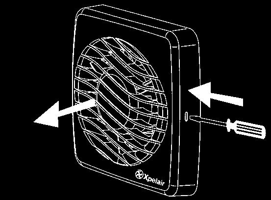
6 GB Xpelair Toilet/Bathroom Fans DX100, DX100PC, DX100T, DX100H, DX100HP DX100PIR & DX100VTD installation & operating instructions Please leave this leaflet with the fan for the benefit of the user 6 3. If the shaft has cavity wall, use the wall tube to bridge the cavity. 4. Fit ducting and condensation trap if necessary, positioning condensation trap as near to the fan as possible. If installing in a ceiling 1. Check there are no buried pipes or cables in the ceiling/joists etc. If in doubt, seek professional advise. 2. Cut a hole 115mm diameter. Preparing the fan for installation Remove the front cover by pressing the release catches located on the sides of the unit with a 3mm screwdriver, whilst pulling the front cover forward L Mount the fan in the hole If working above ground floor level, appropriate safety precautions must be observed. If installing in a wall, ceiling or vent Mark the position of the back plate B 1. Hold the backplate so that the terminal block faces you in the top left hand corner and the lip points towards the hole. 2. Carefully insert the lip into the wall duct/ceiling or vent shaft. 3. Adjust the position of the back plate until it is level. 4. Mark on the wall/ceiling or vent shaft the positions of the three fixing holes in the back plate. 5. Remove the back plate from the ducting. 6. Drill screw holes in these positions if necessary, and fit wall plugs if necessary. Mount the back plate C 1. Push the ribbed gasket (RG100) onto the lip of the back plate 1 2. If installing in a ceiling or vent, push the larger diameter piece of the telescopic wall tube onto the ribbed gasket. Cut the tube to the required length first, if necessary. 3. If wiring the fan from behind, remove knockout. Feed the mains cable through the cable entry hole in the back plate to the terminals D. 4. If wiring from above, leave the cable free to be fitted into labyrinth. 5. Insert the lip of the back plate into the wall duct/ceiling or vent shaft as before. 6. Fasten the back plate to the wall/ceiling or vent shaft using appropriate fasteners. If using screws, do not overtighten the screws. Mount the back draught shutter 1. Peel the backing from the foam strip supplied and attach it around the outside of the lip on the back draught shutter. 2. Go outside. Holding open the top and bottom vanes, insert the lip into the wall duct. 3. Making sure that the back draught shutter is level, mark the positions of the two fixing holes in the top right hand and bottom left hand corners. 4. Remove the back draught from the wall duct. 5. Drill screw holes in these positions, and fit the remaining wall plugs. 6. Holding open the top and bottom vanes, refit the back draught shutter and fasten it to the wall using the pointed and self-tapping screws. Do not over tighten screws. 7. Make sure that the vanes open and shut freely. If installing in window or panel Sealing the hole E 1. If installing in a window or panel no more than 9mm thick, fit the white rubber gasket around the edge of the hole. If installing in a panel or sealed double glazing more than 9mm thick, a DXDG double glazing kit is required. Follow the instructions supplied with the special kit. Attach the back draught shutter to the spacer F 1. Holding the top and bottom vanes, insert the back draught shutter 2 into the spacer 3 so that the fixing holes in the top right and bottom left hand corners match those on the spacer. 2. Insert two of the flat ended self-tapping screws provided and fasten the back draught shutter to the spacer. Mount the fan in the window G 1. Someone else must hold the back draught shutter and spacer in position outside, with the spacer against the glass. 2. Make sure that the two raised fixing holes in the spacer are horizontal and are positioned within the hole. 3. From inside, hold the back plate so that the terminal block faces you in the top left hand corner and the lip points towards that hole. 4. Align the holes in the back plate with those in the spacer. 5. Insert two of the flat ended self-tapping screws provided in the fixing holes, and fasten the back plate to the spacer. Do not overtighten the screws. Wire the electrical connections Make sure the mains supply is isolated, 1. Wire the fan as shown in H check the fan model to diagram, feeding the cable between the two raised pegs, if wiring from above, and through labyrinth to terminal block. 2. Switch off the mains electrical supply and remove fuses 3. Connect the cable from the isolating switch to the electrical supply wiring. For fixed wiring circuits the protective
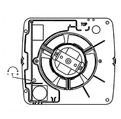
7 fuse for the appliance must not exceed 5A. DX100T only I To adjust the over-run period turn the control (T) clockwise to increase and anti-clockwise to decrease. DX100H & DX100HP only J Humidity operation is factory set at approx. 70% Relative Humidity (RH), but can be adjusted between 50% and 90% RH by control(h). Time delay is factory set at approx. 20 mins, but can be adjusted by control (T). Both controls are adjustable. Turn the controls clockwise to increase time or RH, and anticlockwise to decrease. DX100PIR only K Adjust the overrun period with control (T). Turn screwdriver clockwise to increase and anti-clockwise to decrease. All fans If wiring from above cut out the cable entry slot marked on top of the front cover. Fit the front cover by aligning it square to the duct and pushing it onto the duct until the release catches snap into the slots on the front cover. Using the fan DX100 & DX100VTD only Operate the fan using the on/off switch. Repeat to switch off. DX100PC only Operate the fan by pulling and releasing the cord. Repeat to switch off. DX100T only Operate the fan using the on/off switch. When the switch is turned off, the fan continues to operate for the adjustable time delay. DX100H only Manual mode: use the on/off switch. When you switch off, the fan goes into automatic mode after the time delay (light indicates when fan is operating in manual mode). Automatic mode: fan operates when relative humidity rises and turns off again when humidity drops. DX100PIR only The sensor detects movement in the room and activates the fan. When movement is sensed, the fan will run for a pre-set overrun period and any further movement sensed will re-start the sequence. This ensures that the room is only ventilated during and immediately after use. When the fan is first installed there will be a stabilising period of approximately five minutes. During this time the fan will run for up to two minutes. Cleaning (recommended once a month) A QUALIFIED ELECTRICIAN MUST CARRY OUT ALL CLEANING. 1. Before cleaning, isolate the fan completely from the mains supply. 2. Remove the front cover by pressing the release catches located on the sides at the unit with a 3mm screwdriver, whilst pulling the front cover forward L 3. To clean the front cover, either wipe it with a damp, lint free cloth or wash it in warm soapy water. Thoroughly dry the front cover and refit. 4. Do not immerse the fan in water or other liquids to clean any other parts of the fan. 5. Never use strong solvents to clean the fan. 6. Apart from cleaning, no other maintenance is required. 7
8 Notes DX100, DX100PC, DX100T, DX100H, DX100HP, DX100PIR & DX100VTD 54

9 Do's and dont's Do read all the instruction leaflet before commencing installation. Do install each fan with a double pole isolating switch with a contact gap of 3mm in each pole. Do make sure the mains supply is switched off before attempting to make electrical connections or carry out any maintenance or cleaning Don't install this fan in any window/panel which is less than 4mm thick. Guarantee Customers outside UK - see international below. UK: The fan is guaranteed against defects for 3 years from the date of purchase. Please keep your purchase receipt. If you have any problems, contact Xpelair's Head Office at the address shown below. Technical advice and service Customers outside UK - see international below. UK: Xpelair have a comprehensive range of services including: Free technical advice help-desk from Engineers on all aspects of ventilation. Free design service, quotations and site surveys. Service and maintenance contracts to suit all requirements. Please ask for details: By telephone on Techline: +44 (0) By fax on Techfax: +44 (0) At the address below Head Office, UK Sales Office and Spares Applied Energy Products Ltd, Morley Way, Peterborough, PE2 9JJ England Telephone: +44 (0) Fax: +44 (0) Sales/Spares Hotline: +44 (0) Sales/Spares Faxline: +44 (0) International Guarantee: Contact your local distributor or Xpelair direct for details. Technical Advice and Service: Contact your local Xpelair distributor. Part No (Revision C)
LV100 Standard LV100PC Pull Cord LV100T Timer LV100H Humidistat LV100HP Humidistat and Pull Cord LV100PIR
 Installation and operating instructions LV100 Standard LV100PC Pull Cord LV100T Timer LV100H Humidistat LV100HP Humidistat and Pull Cord Safety extra low voltage toilet/bathroom 100mm fan range Integral
Xpelair Simply Silent TM DX100 Fan
 Xpelair Simply Silent TM DX100 Fan Installation and Maintenance Instructions DX100R (93005AW) / DX100S (93025AW) DX100TR (93006AW) / DX100TS (93026AW) DX100PR (93007AW) / DX100PS (93027AW) DX100HTR (93008AW)
Xpelair Simply Silent DX100
 Xpelair Simply Silent DX100 English Nederlands Installation n and Maintenance Instructions Installa en Onderho ru DX100R (93005AW) DX100S (93025AW) DX100TR (93006AW) DX100TS (93026AW) DX100HPTR (93009AW)
Internal/External Wall/Window Fan Range GX6. Installation and maintenance instructions Retain for future use
 Internal/External Wall/Window Fan Range GX6 Installation and maintenance instructions Retain for future use A GLASS WINDOW B C D ( 6 see F ) 13 E1 E2 E3 G1 G2 G3 G4 H I GB Xpelair GX6, GXC6, GXC6T, GX6HT
Xpelair Simply Silent TM Contour Fan
 Xpelair Simply Silent TM Contour Fan Installation and Maintenance Instructions C4S (92960AW) / C4R (92961AW) C4TS (92962AW) / C4TR (92963AW) C4PS (92964AW) / C4PR (92965AW) C4HTS (92966AW) / C4HTR (92967AW)
Xpelair Simply Silent DX150
 English Xpelair Simply Silent DX150 Installation and Maintenance Instructions DX150S (93070AW) DX150R (93071AW) DX150TS (93072AW) DX150TR (93073AW) DX150PS (93074AW) DX150PR (93075AW) DX150HTS (93076AW)
Simply Silent Contour 4 (100mm) Axial Extraction Fan
 Axial Extraction Fan") Simply Silent Contour 4 (100mm) Axial Extraction Fan Suitable for bathrooms, toilets, shower and utility rooms Controls humidity, odours and mould growth Sleek low-profile design, wall or ceiling mounting
Simply Silent Contour 4 (100mm) Axial Extraction Fan Suitable for bathrooms, toilets, shower and utility rooms Controls humidity, odours and mould growth Sleek low-profile design, wall or ceiling mounting
Xpelair Simply Silent DX100B
 Xpelair Simply Silent DX100B Installation and Maintenance Instructions English DX100BR (92997AW) DX100BS (93017AW) DX100BTR (92998AW) DX100BTS (93018AW) DX100BHTR (92999AW) DX100BHTS (93019AW) DX100BHPTR
airooncentre.co.uk irconcentre.co.uk Xpelair Low Energy Wall/Window Fan Range GX6 EC2 GXC6 EC2 Quick Order Hotline or
 Xpelair Low Energy Wall/Window Fan Range GX6 EC2 GXC6 EC2 Installation and Maintenance Instructions Retain for future reference 3. To remove the impeller, unscrew the central screw with a 7mm nut runner
Xcell 270 Longlife DC wholehouse heat recovery unit
 Xcell 270 Longlife DC wholehouse heat recovery unit Installation and maintenance instructions Xpelair Xcell 270 Longlife DC wholehouse heat recovery unit Xcell 270, Xcell 270BP Please leave this leaflet
IF IN DOUBT, INSTALLATION SHOULD BE MADE BY A QUALIFIED ELECTRICIAN IN ACCORDANCE WITH CURRENT WIRING REGULATIONS.
 INSTALLATION/OPERATING INSTRUCTIONS FOR C100 & C100T Thank you for purchasing a quality Extractor fan from Greenbrook. Please read these instructions fully prior to initial use. Every effort has been made
Installation & Operating Instructions
 Installation & Operating Instructions For 12V Extractor s Models: (4 ) G510SELV, (6 ) G242SELV For 12V Controllers Models: 12VFC, 12VFCT & 12VFCHS Thank you for purchasing a quality 12V Extractor & Controller
Installation & Operating Instructions
 Installation & Operating Instructions For 4 / 100mm Centrifugal s Models: K612 & K612T Thank you for purchasing a quality Centrifugal from GreenBrook. Please read these instructions fully prior to initial
THE BOILING WATER DISPENSER INSTALLATION & OPERATING INSTRUCTIONS IMPORTANT: READ AND SAVE THESE INSTRUCTIONS FOR THE BENEFIT OF THE USER
 THE BOILING WATER DISPENSER INSTALLATION & OPERATING INSTRUCTIONS IMPORTANT: READ AND SAVE THESE INSTRUCTIONS FOR THE BENEFIT OF THE USER Thank you for choosing a quality Redring product manufactured by
T-SERIES. Wall & Panel Models. Installation, Set-up and Operating Instructions. 230V/1/50Hz
 T-SERIES Wall & Panel Models Installation, Set-up and Operating Instructions Stock Ref. Nos. WIRED 456166A (9" WL) 456167A (9" PL) 456174A (12" WL) 456175A (12" PL) WIRELESS 456170A (9" WL) 456171A (9"
T-SERIES. Window & Roof Models. Installation, Set-up and Operating Instructions. 230V/1/50Hz
 T-SERIES Window & Roof Models Installation, Set-up and Operating Instructions Stock Ref. Nos. WIRED 456165A (9" WW) 456168A (9" RF) 456173A (12" WW) 456176A (12" RF) WIRELESS 456169A (9" WW) 456172A (9"
Lo-Carbon SELV Tempra
 Lo-Carbon SELV Tempra THROUGH THE WALL HEAT RECOVERY FAN Installation and Wiring Instructions DRAFT Stock Ref. N 444368 Pullcord. (SVP) 444369 Timer. (SVT) 444370 Humidistat -Timer Pullcord. (SVHTP) 220-240V~50Hz
PLEASE READ INSTRUCTIONS IN CONJUNCTION WITH ILLUSTRATIONS.
 Silhouette Lo-Carbon RANGE 100/150mm AXIAL EXTRACT FAN Installation and Wiring Instructions Stock Ref. N 44 16 24-100B 44 16 25-100T 44 16 26-100HT 44 16 28-150B 44 16 29-150T 44 16 30-150HT 220-240V~50Hz
Lo-Carbon T-series Window & Roof Models
 Lo-Carbon T-series Window & Roof Models Installation & User Instructions WIRED 456165A (9 WW) 456168A (9 RF) 456173A (12 WW) 456176A (12 RF) WIRELESS 456169A (9 WW) 456172A (9 RF) 456177A (12 WW) 456180A
PLEASE READ INSTRUCTIONS IN CONJUNCTION WITH ILLUSTRATIONS.
 Silhouette Installation and Wiring Instructions Stock Ref. N 45 40 55B (100B) 44 51 61 (125B) 45 40 59B (150X) 45 40 56B (100T) 44 51 62 (125T) 45 40 60B (150XT) 45 40 57B (100HT) 44 51 63 (125HT) 45 40
PLEASE READ INSTRUCTIONS IN CONJUNCTION WITH ILLUSTRATIONS. PLEASE SAVE THESE INSTRUCTIONS.
 Eclipse Installation and Wiring Instructions Models Eclipse 100X Eclipse 100XP Eclipse 100XT Eclipse 150X Eclipse 150XP Ref No. 42 73 10A 42 72 81A 42 72 82A 42 72 83A 42 73 13A 220-240V~50Hz PLEASE READ
Centrif Duo & Centrif Duo Plus
 Centrif Duo & Centrif Duo Plus Installation and Wiring Instructions Stock Ref. N Centrif Duo P 25 61 20D Centrif Duo T 25 62 20D Centrif Duo DP 25 63 20D Centrif Duo HTP 25 64 20D Centrif Duo Centrif Duo
Centrifugal extract and condensation control fans
 Approvals: BEAB CE 3yr Guarantee Zone 1 Zone 2 The Premier range of pressure developing fans is designed specifically for domestic applications, where longer duct runs are required. Key features Type:
Lo-Carbon Quadra SELV
 Lo-Carbon Quadra SELV Installation and Wiring Instructions Stock Ref. N Quadra SVTP 442865 Quadra SVHTP 442866 Quadra SVTM 442867 Safety Extra Low Voltage IPX7 PLEASE READ INSTRUCTIONS IN CONJUNCTION WITH
ELIX 1003 IPX4. Energy Efficient Centrifugal Fan with EC Motor Installation and Operating Instructions
 ELIX 1003 Energy Efficient Centrifugal Fan with EC Motor Installation and Operating Instructions 3 speed continuous running SAP Appendix Q Eligible 3 models: - standard - timer - humidity control for all
Lo-Carbon Quadra Centrifugal Fan
 Lo-Carbon Quadra Centrifugal Fan Installation and Wiring Instructions Stock Ref. N Quadra TP Quadra TM Quadra HTP 439251A 439253A 439181A 220-240V~50Hz IPX4 PLEASE READ INSTRUCTIONS IN CONJUNCTION WITH
EXTRACTOR HOOD. Please read all the instructions carefully before starting the installation. 230 / 240V 50Hz
 abc EXTRACTOR HOOD Please read all the instructions carefully before starting the installation Model Stock Ref Napoli 120812 Napoli Plus (white) 436083 Napoli Plus (Silver) 436084 230 / 240V 50Hz PLEASE
BWT6.3GL Cooker Hood 60 cm Glass chimney hood
 User Manual for your BWT6.3GL Cooker Hood 60 cm Glass chimney hood NOTE: This User Instruction Manual contains important information, including safety & installation points, which will enable you to get
DC Heat Recovery Unit MVHR Wholehouse heat recovery unit
 DC Heat Recovery Unit MVHR Wholehouse heat recovery unit Stock Ref. N DC Heat Recovery Unit MVHR 443423 Installation, Maintenance & Users Instructions PLEASE READ INSTRUCTIONS IN CONJUNCTION WITH ILLUSTRATIONS.
COOKER HOOD USER HANDBOOK FOR INSTALLATION AND OPERATION MODELS CRC95
 COOKER HOOD USER HANDBOOK FOR INSTALLATION AND OPERATION MODELS CRC95 Your new Cooker Hood Using your new Cooker Hood is very simple. Nevertheless, to get the best results it is important that you read
REDRING POWERSTREAM UNVENTED INSTANTANEOUS WATER HEATER. Installation and User Guide
 : GUARANTEE AND CONTACT DETAILS REDRING POWERSTREAM UNVENTED INSTANTANEOUS WATER HEATER Installation and User Guide APPLIED ENERGY PRODUCTS LIMITED MORLEY WAY, PETERBOROUGH PE2 JJ TEL: +44 (0) 844 372
ELEGANCE IPX4 IPX7. Low Carbon Fan with EC Motor Installation and Operating Instructions. 6 models:
 ELEGANCE Low Carbon Fan with EC Motor Installation and Operating Instructions 6 models: - SAP Appendix Q Eligible 3 speed continuous running - timer - humidity control - SELV - low voltage for all domestic
IXL Eco Ventflo. User Guide. Model: (200mm) - Extraction Rate: 340m 3 /h Model: (250mm) - Extraction Rate: 490m 3 /h
 - Extraction Rate: 340m 3 /h Model: (250mm) - Extraction Rate: 490m 3 /h") User Guide Model: 10324 (200mm) - Extraction Rate: 340m 3 /h Model: 10326 (250mm) - Extraction Rate: 490m 3 /h Electrical Rating: 230~240 V. 50 Hz. Welcome Safety Thank you for buying this Fan. Even if
User Guide Model: 10324 (200mm) - Extraction Rate: 340m 3 /h Model: 10326 (250mm) - Extraction Rate: 490m 3 /h Electrical Rating: 230~240 V. 50 Hz. Welcome Safety Thank you for buying this Fan. Even if
BWTC6510GL Cooker Hood 60 cm Glass cooker hood in stainless steel. BWTC9510GL Cooker Hood 90 cm Glass cooker hood in stainless steel
 User Manual for your BWTC6510GL Cooker Hood 60 cm Glass cooker hood in stainless steel BWTC9510GL Cooker Hood 90 cm Glass cooker hood in stainless steel NOTE: This User Instruction Manual contains important
Vent-Axia Svara Multifunctional app controlled fan. Important Information 2 Installation and Wiring Instructions 3-11 Accessories 12 Pin Code 12
 Vent-Axia Svara Multifunctional app controlled fan Important Information 2 Installation and Wiring Instructions 3- Accessories 2 Pin Code 2 6 2 Ø99 Ø77 Important: READ THESE INSTRUCTIONS BEFORE COMMENCING
PLEASE READ INSTRUCTIONS IN CONJUNCTION WITH ILLUSTRATIONS.
 VA100 Lo-Carbon RANGE 100mm AXIAL EXTRACT FAN Installation and Wiring Instructions Stock Ref. N 44 31 59 - LP 44 31 60 - XP 44 31 61 - LT 44 31 62 - XT 44 31 63 - LHTP 44 31 64 - XHTP 220-240V~50Hz PLEASE
60cm Chimney Extractor
 60cm Chimney Extractor LAM2401 HJA2480 User & Installation Guide Contents Page Environmental note 3 IMPORTANT SAFETY INFORMATION 4 6 Specifications of your extractor 7 8 Dimensions 7 Specifications 7-8
BT16.4SS-HK BT19.4SS-HK Cooker Hood
 BT16.4SS-HK BT19.4SS-HK Cooker Hood User Manual for your Baumatic User Manual for your Baumatic BT16.4SS-HK 60 cm Chimney Hood BT19.4SS-HK 90 cm Chimney Hood NOTE: This User Instruction Manual contains
GUH52SD 52 cm GUH75 75 cm Canopy Hood
 User Manual for your GUH52SD 52 cm GUH75 75 cm Canopy Hood NOTE: This User Instruction Manual contains important information, including safety & installation points, which will enable you to get the most
GUH90 90 cm Canopy Hood
 User Manual for your GUH90 90 cm Canopy Hood NOTE: This User Instruction Manual contains important information, including safety & installation points, which will enable you to get the most out of your
HW3 Handwash Installation and Operating Instructions
 HW3[16]instructions 10/12/15 14:05 Page 1 HW3 Handwash Installation and Operating Instructions IMPORTANT SAFEGUARDS SPECIFICATION: HW3 RATING: 230-240V, 3000W, ~50Hz; DIMENSIONS: 170w x 190h x 80d mm;
BOILING UNIT REDITAP. Installation and User Guide. IMPORTANT: This booklet should be left with the user after installation and demonstration
 in tap Boiling water to in tap sink Drain Valve (as high as possible) REDITAP CONNECTION SUMMARY Amp mains supply cold mains water into in tap optional filter cold water in hot water BOILING UNIT Installation
WHHR Midi & Midi Lite
 WHHR Midi & Midi Lite Residential Whole House Heat Recovery Units with Low Energy EC Motors Optional - Integral LCD Installation, Operating and Maintenance Instructions Image of model with LCD screen Page
Instruction Manual JLHDA cm Cooker hood
 Contents 3 Introduction 3 Safety is important 3 In the box 4 Safety information 4 Important safety information 4 Warnings 5 Cautions 5 Electrical information 6 Remote control 6 Programming the remote control
INTEGRA PLUS ABC. 230V~ 50Hz. Stock Ref. N. Installation and Wiring Instructions IPX2
 INTEGRA PLUS Installation and Wiring Instructions Stock Ref. N INTEGRA PLUS 437666 230V~ 50Hz ABC PLEASE READ INSTRUCTIONS IN CONJUNCTION WITH ILLUSTRATIONS. PLEASE SAVE THESE INSTRUCTIONS. IPX2 VENT-AXIA
VA 150 A, VA 150 P WINDOW EXTRACT FAN. Installation and Wiring Instructions V/1/50Hz
 VA 150 A, VA 150 P WINDOW EXTRACT FAN Installation and Wiring Instructions VA150 P STOCK Ref: 152110B VA150 A STOCK Ref: 153110B 220-240V/1/50Hz READ INSTRUCTIONS IN CONJUNCTION WITH ILLUSTRATIONS PLEASE
Lo-Carbon MULTIVENT MVDC-MS & MVDC-MS H VENTILATION SYSTEMS V~50Hz. Installation and Wiring Instructions IP22. Stock Ref.
 Lo-Carbon MULTIVENT MVDC-MS & VENTILATION SYSTEMS Installation and Wiring Instructions Stock Ref. N MVDC-MS 76A 98 0-0V~50Hz PLEASE READ INSTRUCTIONS IN CONJUNCTION WITH THE ILLUSTRATIONS. PLEASE SAVE
User Manual for your GEH6017 & GEH9017 Cooker Hood
 User Manual for your GEH6017 & GEH9017 Cooker Hood NOTE: This User Instruction Manual contains important information, including safety & installation points, which will enable you to get the most out of
SHOWER HANDBOOK IMPORTANT
 SHOWER HANDBOOK IMPORTANT This booklet should be given to the customer after installation and demonstration. Thank you for choosing a quality Redring product manufactured in Peterborough, England. Contents
Silhouette Installation and Wiring Instructions
 Silhouette Installation and Wiring Instructions Stock Ref. N 45 40 55B (100B) 44 51 61 (125B) 45 40 59B (150X) 45 40 56B (100T) 44 51 62 (125T) 45 40 60B (150XT) 45 40 57B (100HT) 44 51 63 (125HT) 45 40
Drying Cabinet Installation and Operating Manual
 Drying Cabinet Models:- ETS-1900H ETS-1900TR CONTENTS ABOUT THE USER MANUAL Page 2 IDENTIFICATION DATA PLATE Page 2 IMPORTANT SAFETY INSTRUCTIONS Page 3 INSTALLATION INSTRUCTIONS Page 4 OPERATING INSTRUCTIONS
EKF. EC kitchen extract fan range. Installation and Wiring Instructions. Stock Ref. N EKF355E1 EKF400E1 EKF450E1 EKF450E3 EKF500E3 EKF560E3
 EKF EC kitchen extract fan range Installation and Wiring Instructions Stock Ref. N EKF355E1 EKF400E1 EKF450E1 EKF450E3 EKF500E3 EKF560E3 PLEASE READ INSTRUCTIONS IN CONJUNCTION WITH THE ILLUSTRATIONS.
100cm Chimney Hood GB IE
 100cm Chimney Hood GB IE [01] x 1 [02] x 2 [03] x 2 [04] x 2 [05] x 3 [06] x 1 [07] x 1 1 : 1 [09] x 8 (3.9 x 32mm) [08] x 8 [10] x 4 (4 x 12mm) 100cm Chimney Hood GB IE Cooker Hood 04 FR Hotte Aspirante
GEH9026G Cooker Hood
 User Manual for your GEH9026G Cooker Hood 90 cm Chimney Hood in Stainless Steel NOTE: This User Instruction Manual contains important information, including safety & installation points, which will enable
User and maintenance manual
 GB User and maintenance manual IMPORTANT SAFETY INSTRUCTIONS These instructions shall also be available on website: docs.whirlpool.eu. YOUR SAFETY AND THAT OF OTHERS IS HIGHLY IMPORTANT. This manual and
Installation and Maintenance. Opus OK / Genie NKF1 Kitchen Extract Unit. Contents IMPORTANT WARNING IMPORTANT! Introduction WARNING!
 Installation and Maintenance Opus OK / Genie KF Kitchen Extract Unit uaire imited Western Industrial Estate Caerphilly, Mid Glamorgan CF8 XH Telephone: 09 088 59 Facsimile: 09 088 70 Email: info@nuaire.co.uk
D100, D125 & D150. Installation Instructions
 D100, D125 & D150 Installation Instructions 100mm 125mm 150mm 34 l/s (124 m 3 /h) 50 l/s (180 m 3 /h) 61 l/s (277 m 3 /h) IP22/IP24 IP22 IP22 40W 60W 20W 23W 25W 40 C 40 C 40 C kg 1.3 kg 1.4 kg 1.5 kg
INSTALLER AND OWNER GUIDE
 5110831/03 INSTALLER AND OWNER GUIDE Model 808 Electric Heater This guide is intended to help you install and care for your Baxi Fires Division electric heater. Please read carefully before installing
CLASSIC-100. Instruction leaflet. Instruction leaflet
 CASSIC-100 Instruction leaflet Instruction leaflet CASSIC-100 AXIA EXTRACTOR FAS Suitable for bathroom applications Thank you for placing your confidence in EnviroVent by buying this product. It has been
ART cm Island Curved Glass
 ART28101 90cm Island Curved Glass [01] x 1 [02] x 1 [03] x 1 [04] x 1 [05] x 4 [06] x 1 [07] x 1 [08] x 1 [09] x 4 [10] x 4 [11] x 1 [12] x 4 (6x70mm) [13] x 4 (6.3x17x2mm) [14] x 8 (4x12x1mm) [15] x 4
Mobile Air Conditioner Instruction Manual Model TC-N9KM
 Mobile Air Conditioner Instruction Manual Model TC-N9KM Please read and retain these instructions for future reference SPECIFICATION Model no. Cooling capacity Power/Ampere consumption for cooling* Air
FM900. Installation, Operation and Maintenance Instructions. Built-In Extractor
 FM900 Installation, Operation and Maintenance Instructions Built-In Extractor Contents: 1 Introduction 2 Important Information 3 Extraction Performance 4 Installation 5 Operating Instructions 6 Maintenance
GB User and maintenance manual
 GB User and maintenance manual IMPORTANT SAFETY INSTRUCTIONS These instructions shall also be available on website: docs.whirlpool.eu. YOUR SAFETY AND THAT OF OTHERS IS VERY IMPORTANT This manual and
Installation and Operating Manual Drying Cabinet
 Drying Cabinet TS-4175 WW CONTENTS THIS USER MANUAL & DATA PLATE DETAILS Page 2 IMPORTANT SAFETY INSTRUCTIONS Page 3 INSTALLATION INSTRUCTIONS Page 4 OPERATING INSTRUCTIONS Page 8 MAINTENANCE INSTRUCTIONS
1500W Black Glass Portable Electric Panel Heater KAHTP20BLKA
 1500W Black Glass Portable Electric Panel Heater KAHTP20BLKA Attention Please handle this product with care and inspect it regularly to ensure it is in good working order. If the product, power supply
Trimbox Mixed Flow Fans. Product Manual. ventilation systems TP220T TP221T TP222T TP223T
 EN Trimbox Mixed Flow Fans TP220T TP221T TP222T TP223T Product Manual ventilation systems Safety Information Important Information Important: read these instructions fully before the installation of this
Conception Wall Fire. Instruction Manual THE SCIENCE BEHIND CLEAN.
 Conception Wall Fire Instruction Manual BEHIND CLEAN www.beldray.com Please read all of the instructions carefully and retain for future reference. Safety Instructions When using electrical appliances,
Glass Chimney Hood. Installation & User Instructions Please keep for future reference
 Glass Chimney Hood Installation & User Instructions Please keep for future reference 4897549 4897556 Important Please read these instructions fully before installing or using These instructions contain
FAITH (dmev) 230V / 24V DC SELV Flush Mounted Domestic Continuous Extract Fans
 230V / 24V DC SELV Flush Mounted Domestic Continuous Extract Fans") FAITH (dmev) 230V / 24V DC SELV Flush Mounted Domestic Continuous Extract Fans Installation and Maintenance IPX4* The EMC Directive 2014/30/EU The Low Voltage Directive 2014/35/EU 1.0 SAFETY INFORMATION
FAITH (dmev) 230V / 24V DC SELV Flush Mounted Domestic Continuous Extract Fans Installation and Maintenance IPX4* The EMC Directive 2014/30/EU The Low Voltage Directive 2014/35/EU 1.0 SAFETY INFORMATION
I n s t r u c t i o n m a n u a l f o r b u i l t - i n h o o d. Model code: BORA600
 I n s t r u c t i o n m a n u a l f o r b u i l t - i n h o o d Model code: BORA600 Contact Caple on 0844 8003830 or for spare parts www.4caple.co.uk 1 Y O U R A P P L I A N C E Thank you for buying your
"Microbox" DC Models MBOX 125/2DC MBOX 125/2DC204
 "Microbox" DC Models MBOX 125/2DC MBOX 125/2DC204 Continuous Mechanical Extract Ventilation Unit with Low Energy DC Motor - for domestic and commercial use Installation, Operating and Maintenance Instructions
Lo-Carbon Quadra Centrifugal Fan
 Lo-Carbon Quadra Centrifugal Fan Installation and Wiring Instructions Stock Ref. N Quadra TP Quadra TM Quadra HTP 439251A 439253A 439181A 220-240V~50Hz IPX4 PLEASE READ INSTRUCTIONS IN CONJUNCTION WITH
INSTALLATION AND USER S MANUAL COOKER HOOD RS-600/A-S
 INSTALLATION AND USER S MANUAL COOKER HOOD RS-600/A-S RS-600 (CHS60SS)-GB-05.indd 1 6/8/2010 9:30:59 AM TABLE OF CONTENTS 1. Introduction 2 2. Safety precaution 2 3. Intended use 3 4. Parts supplied 3
HR200WK Through the wall Heat Recovery Ventilator
 HR200WK Through the wall Heat Recovery Ventilator Installation and Maintenance Instructions Stock Ref No:- HR200WK 14120020 PLEASE READ INSTRUCTIONS IN CONJUNCTION WITH ILLUSTRATIONS. PLEASE SAVE THESE
Contact Details. Please note that some of the contact details on this PDF document may not be current.
 Contact Details Please note that some of the contact details on this PDF document may not be current. Please use the following details if you need to contact us: Telephone: 0844 879 3588 Email: customer.services@gdcgroup.co.uk
"WHHR125DC" Whole House Heat Recovery Unit with Low Energy DC Motor. Installation, Operating and Maintenance Instructions domestic and commercial use
 "WHHR125DC" Whole House Heat Recovery Unit with Low Energy DC Motor Installation, Operating and Maintenance Instructions domestic and commercial use Page 2 Contents Section Page Number Introduction 3 How
Instruction Manual JLCHDD601/JLCHDD901 60cm/90cm Cooker hood
 Contents 3 Introduction 3 Safety is important 3 In the box 4 Safety information 4 Important safety information 4 Warnings 5 Cautions 5 Electrical information 6 Operation 6 Automatic shut-down 7 Care and
Imperial Electric Fires
 Imperial Electric Fires GB IE MODELS: Flamescape III & Curvascape III manual / remote Installation and User Instructions PLEASE READ THESE INSTRUCTIONS CAREFULLY AND RETAIN FOR FUTURE REFERENCE This electric
Instructions for use
 Instructions for use These instructions are also available on the website: www.kitchenaid.eu Important instructions for safety 4 Installation 6 Safeguarding the environment 6 Troubleshooting guide 7 After-sales
HOTLINE:
 You are about to install a product that is designed to outlast the life-cycle of the building. Once installed the unit will operate continuously for 5 years and beyond without a major service. Please therefore
CG60/ 70/ 80/ 90/ 100 SS/BK
 CG60/ 70/ 80/ 90/ 100 SS/BK GB IE [01] x 1 [02] x 1 [03] x 1 [04] x 2 [05] x 1 [06] x 1 [07] x 1 [08] x 4 [09] x 4 [10] x 1 [11] x 6 1 : 1 [12] x 4 [13] x 6 (3.9 x 32mm) [14] x 4 (3.4 x 10mm) CG60/ 70/
 1600W WALL MOUNTED HAIR DRYER COI0016_V3_070814 USE & CARE MANUAL www.corbyofwindsor.com SECTION 01 These notes must be read before installation These instructions are for your safety. Please read through
360 Surface Mount Ceiling PIR Light Controller
 360 Surface Mount Ceiling PIR Light Controller Model: SLW360L Installation & Operating Instructions 1 1. General Information These instructions should be read carefully and retained for further reference
INSTALLATION INSTRUCTIONS USER GUIDE
 INSTALLATION INSTRUCTIONS USER GUIDE Tilted wall cooker hood HT90GHB2 model GB IE CONTENTS Introduction 3 Safety and warnings 4 Installation instructions 8 About your cooker hood Energy efficiency 18
REDRING POWERSTREAM UNVENTED INSTANTANEOUS WATER HEATER. Installation and User Guide
 REDRING POWERSTREAM UNVENTED INSTANTANEOUS WATER HEATER Installation and User Guide IMPORTANT: This booklet should be left with the user after installation and demonstration. It should be kept in a safe
(SP4) SP420 (SP5) SP520 (SP9) SP920 AUS/NZ. 08/50019/5 Issue 5
 SP420 (SP5) SP520 (SP9) SP920 AUS/NZ. 08/50019/5 Issue 5") (SP4) SP420 (SP5) SP520 (SP9) SP920 AUS/NZ 08/50019/5 Issue 5 Products comply with the European Safety Standard: EN 60335-2-30 and the European Standards for Electromagetic Compatibility (EMC) EN55014-1
(SP4) SP420 (SP5) SP520 (SP9) SP920 AUS/NZ 08/50019/5 Issue 5 Products comply with the European Safety Standard: EN 60335-2-30 and the European Standards for Electromagetic Compatibility (EMC) EN55014-1
Baxi Combi 133 HE Plus Baxi Combi 100 HE Plus Baxi Combi 80 HE Plus. User s Operating Instructions
 User s Operating Instructions Baxi Combi 133 HE Plus Baxi Combi 100 HE Plus Baxi Combi 80 HE Plus Gas Fired Wall Mounted Condensing Combination Boiler Please keep these instructions safe. Should you move
Unity CV2GIP Decentralised Mechanical Extract Ventilation (dmev) Installation Instructions
 Installation Instructions") Unity CV2GIP Decentralised Mechanical Extract Ventilation (dmev) Installation Instructions Commissioning Data: To be completed by the Commissioning Engineer. Refer to User / Homeowner Guide also supplied.
Unity CV2GIP Decentralised Mechanical Extract Ventilation (dmev) Installation Instructions Commissioning Data: To be completed by the Commissioning Engineer. Refer to User / Homeowner Guide also supplied.
isense & isense-ht 230V Flush Mounted Domestic Continuous Extract Fans
 isense & isense-ht 230V Flush Mounted Domestic Continuous Extract Fans Installation and Maintenance IPX4* The EMC Directive 2014/30/EU The Low Voltage Directive 2014/35/EU 1.0 SAFETY INFORMATI The installation
Cooker Hood CHIM60 CHIM70 CHIM90 CHIM101 CHIM110. Installation & User s instructions
 Cooker Hood CHIM60 CHIM70 CHIM90 CHIM101 CHIM110 Installation & User s instructions 2 250 20.5 167.5 A 590 : 960 260 330 Max 370 E F 304 278 42 206 167 Z B C D 230 230 Fig.1 Fig.3 G E A Z Z F B Y C D 490
DESIGNER WALL CANOPY
 DESIGNER WALL CANOPY HC60DCXB1, HC90DCXB1 & HC120DCXB1 Models INSTALLATION GUIDE / USER GUIDE CN Made in Spain Contents Safety and warnings 1 Preparing to install 3 Installation instructions 4 Operating
MEV SPIDER INSTALLATION GUIDE FOR ENGINEER / INSTALLER
 MEV SPIDER INSTALLATION GUIDE FOR ENGINEER / INSTALLER Safety IMPORTANT Be sure to have read and understood these instructions before beginning the installation process. PRE-INSTALLATION CHECK LIST Make
Imperial Electric Fires
 Imperial Electric Fires GB IE MODELS: Flamescape II Curvascape II manual & remote. Installation and User Instructions PLEASE READ THESE INSTRUCTIONS CAREFULLY AND RETAIN FOR FUTURE REFERENCE This electric
USER MANUAL CANOPY RANGE HOODS - SLIM LINE ACS60AX-L, ACS90AX-L, ACT60AX-L & ACT90AX-L
 USER MANUAL CANOPY RANGE HOODS - SLIM LINE ACS60AX-L, ACS90AX-L, ACT60AX-L & ACT90AX-L IMPORTANT // Please ensure that you read through this manual prior to installation and use. This user manual contains
UBGHFF60W 60cm Gas on Glass Gas Hob
 UBGHFF60W 60cm Gas on Glass Gas Hob GB [02] x 1 [03] x 2 [04] x 1 [01] x 1 [08] x 4 [05] x 2 [09] x 1 [06] x 1 [07] x 4 [10] x 4 [11] x 1 TEMPLATE TEMPLATE UBGHFF60W GB Built-in 60cm Gas on Glass Gas Hob
EH0533 Indoor Climate Control
 EH0533 Indoor Climate Control 2.8 kw of cooling, 2.9 kw of heating Air Conditioning Efficient heating (air-source heat-pump) Cooling Remote control Suitable for low-wall installation No external unit required
Manual and Thermostatic Power Shower Units
 520M/520TS Manual and Thermostatic Power Shower Units Installation instructions & User guide IMPORTANT: This booklet should be given to the customer after installation and demonstration. WARNING: Under
VA100 SELV 12 RANGE. Installation and Wiring Instructions IPX7
 VA100 SEV 12 RAGE Installation and Wiring Instructions Stock Ref. VA100SV12 VA100SVX12 VA100SVXT12 VA100SVH12 VA100SVXH12 VA100SVXHT12 25 81 10D 25 83 10D 25 84 10D 25 81 12E 25 83 12E 25 85 12B FA UITS
BFR6 / BFR9 Rangehood
 BFR6 / BFR9 Rangehood User Manual for your Baumatic BFR6, 60 cm Rangehood BFR9, 90 cm Rangehood NOTE: This User Instruction Manual contains important information, including safety & installation points,
Lucci Designer Hi Flow Exhaust Fan
 USE AND CARE INSTRUCTION INSTALLATION INSTRUCTION Lucci Designer Hi Flow Exhaust Fan SKU# 200265&200267 MXSQ8PW(200mm) SKU# 200266&200268 MXSQ10PW(250mm) Dear Customers, Thank you for selecting a LUCCI