Cooling test results C-side replacement detector
|
|
|
- Helen Hodges
- 6 years ago
- Views:
Transcription

1 Cooling test results C-side replacement detector Nikhef number: Item number: Date: 2/10/2011 Page: 1 of MT AA2232 Status: In Work Revision: A.5 Project: LHCb VELO Department: Mechanical Technology Top folder: CO2 cooling Abstract: The quality of the VTCS CO 2 evaporators of the VELO C-side is tested. The CO 2 evaporators are mounted in the VELO C-side and connected to a CO 2 cooling system. The performance tests will be done for the VELO placed in the trolley in vertical orientation and for a horizontal VELO, which is the orientation of the VELO detector in LHCb. Created by: K. de Roo Distribution list: Checked by: Approved by: National Institute for Subatomic Physics Science Park 105, 1098 XG Amsterdam The Netherlands
2 1 ABSTRACT The cooling performance of all CO 2 evaporators of the VELO replacement detector halves is measured with the Nikhef Green Cooler setup. The results are very similar to results of the presently installed VELO detector measured in 2006 at Nikhef with the prototype of a CO 2 cooling system. The CO 2 evaporators perform well, for a total CO 2 mass flow above 6 g/s and for a maximal heat load of 30 W on each of the 23 module heat exchangers (evaporators). The operational conditions for the VELO Thermal Control System at CERN are more comfortable with a total CO 2 mass flow of 10 g/s per detector half and a heat load of 16 W, from the Beetle readout chips, per module. The tests are done in a horizontal orientation of the detector halves as they will be used at CERN and in a vertical orientation as a detector half is mounted in the transport trolley. The CO 2 evaporators perform well even at 4 g/s, apart from the capillaries that are positioned highest in the CO 2 inlet manifold in the concerned orientation. The CO 2 in front of the manifold consists of liquid with a low vapour quality and the vapour enters, due to gravity, the capillaries in the top of the manifold. Due to the small cooling capacity of vaporized CO 2 these capillaries will heat up first at a relative high total CO 2 mass flow. 2
3 Contents 1 ABSTRACT PERFORMANCE CO 2 EVAPORATORS VELO REPLACEMENT C-SIDE TEST SETUP CO 2 COOLING EVAPORATORS GREEN COOLER ENTHALPY CONTROL IN THE GREEN COOLER TEST PROTOCOL LABELS AND NUMBERING OF THE VELO C-SIDE FLOW REDUCTION TEST WITH A POWER OF 15 WATT AND A COOLING TEMPERATURE OF -30 C FIRST MASS FLOW REDUCTION TEST WITH 15 WATT IN THE VELO SECOND MASS FLOW REDUCTION TEST WITH 15 WATT THIRD MASS FLOW REDUCTION TEST WITH 19 WATT FLOW REDUCTION TEST WITH A POWER OF 25 WATT AND A COOLING TEMPERATURE OF -20 C FLOW REDUCTION TEST WITH A POWER OF 30 WATT AND A COOLING TEMPERATURE OF -20 C IN THE VELO FLOW REDUCTION TEST WITH A POWER OF 25 WATT AND A COOLING TEMPERATURE OF -20 C IN A HORIZONTAL VELO FIRST FLOW REDUCTION TEST WITH 25 WATT IN A HORIZONTAL VELO SECOND FLOW REDUCTION TEST WITH 25 WATT IN A HORIZONTAL VELO FLOW REDUCTION TEST WITH A POWER OF 30 WATT AND A COOLING TEMPERATURE OF -20 C IN A HORIZONTAL VELO FIRST FLOW REDUCTION TEST WITH 30 WATT IN A HORIZONTAL VELO SECOND FLOW REDUCTION TEST WITH 30 WATT IN A HORIZONTAL VELO FAST FLOW REDUCTION TEST WITH 30 WATT IN A HORIZONTAL VELO HEAT UP ORDER FOR ALL CO 2 EVAPORATORS CONCLUSION
4 2 PERFORMANCE CO 2 EVAPORATORS VELO REPLACEMENT C-SIDE The VELO contains detectors of silicon, designed to record and reconstruct the positions of traversing particles. The damage to the detectors as a consequence of radiation can be minimized by cooling the detector modules at a cooling temperature of approximately -30 C. The cooling system of the detector modules should be able to cool a minimal heat load of 16 Watt, from the Beetle readout chips, per detector module. A two phase CO 2 cooling system is installed and is operating for the VELO detector halves in operation. Replacement VELO halves are constructed to replace the current halves when necessary. These replacement halves will contain new detector modules and thereby new CO 2 cooling evaporators. The cooling performance of these CO 2 cooling evaporators is tested at Nikhef with a two phase CO 2 cooling system, the Green Cooler. To get an impression of the cooling performance of the CO 2 cooling evaporators the temperature of the evaporators and pressure drop over the VELO is monitored as the total CO 2 mass flow through the VELO cooling system is reduced in steps. When the cooling capacity of an evaporator becomes insufficient due to the low mass flow, the temperature of the evaporator will rise. The increase in temperature of the evaporators must occur well below the 10 g/s of the VELO Thermal Cooling System at CERN. The pressure drop over the VELO gives a view of the quality of the capillaries. When the return line of VELO is connected to the cooling system with the smallest resistance possible, the minimal pressure in the VELO is equal to the pressure of the accumulator of the cooling system. The maximal pressure before the evaporators depends on the resistance of the capillaries. If the resistance of the capillaries is too low, the CO 2 mass flow enters the two phase area before reaching the evaporators. If the resistance of the capillaries differ much, the distribution of the mass flow in the manifold won t be equal and thus the cooling capacity per capillary differs much. The pressure drop over the VELO at a total CO 2 mass flow of 10 g/s, a cooling temperature of -30 C and a power of 25 Watt should be approximately 2.1 bar. 4


5 3 TEST SETUP In Figure 1 the VELO replacement detector mounted on the transport trolley is shown. The replacement detector is connected to the two phase CO 2 cooling system, the Green Cooler by means of two transfer lines. Figure 1: VELO test setup 3.1 CO 2 cooling evaporators The 23 modules of the VELO are cooled with 23 evaporators. A CO 2 flow is led by a capillary through five aluminium cookies, one evaporator. Due to the heat that is transferred from the modules to the evaporators the CO 2 starts to boil. As a consequence of evaporation of the liquid CO 2 the cooling temperature of the fluid remains constant. During the test phase, aluminium blocks are mounted to the evaporators. By means of resistors, which are mounted on the blocks, heat is added to the evaporators. Figure 2: Evaporators with aluminum blocks and resistors 5

6 3.2 Green Cooler A schematic view of the two phase CO 2 cooling system Green Cooler is shown Figure 3. The cooling system consists of a CO 2 cooling system and a primary cooling system. The primary cooling system extracts heat from the CO 2 in the accumulator and the heat exchanger in the CO 2 system. The cooling temperature of an experiment connected to the Green Cooler is controlled by the accumulator. This system is a two phase cooling system, thus controlling the pressure in the system by means of controlling the evaporation temperature of the CO 2 and thereby the cooling temperature in the experiment. By adding or extracting heat from the CO 2 in the accumulator, the pressure is changed in the accumulator and thus in the CO 2 cooling system. The accumulator is placed behind the experiment so that the pressure in the accumulator is equal to the pressure in the experiment if they are in direct contact. The cooling cycle of the Green Cooler is as follows. The pressure of liquid CO 2 is increased by gear pumps and the mass flow is measured with a mass flow meter. The enthalpy of the CO 2 before the experiment is controlled with heater HT105 of the enthalpy control. After passing the enthalpy control the CO 2 reaches the experiment and experiences a pressure drop from a restriction or the capillaries of the experiment. The CO 2 will evaporate in the experiment due to the added heat and the partially evaporated CO 2 is led back to the heat exchanger where it is condensed back to liquid CO 2. The liquid CO 2 is led to the gear pumps. Figure 3: Schematic view of the Green Cooler (Verlaat, 2010) 6
7 3.3 Enthalpy control in the Green Cooler The enthalpy control in the Green Cooler consists of a heater (HT105) which is controlled by an algorithm to reach the set enthalpy. With pressure sensor PT106 and temperature sensor TT106 the enthalpy of liquid CO 2 can be determined by means of a calculation based on the dataset of the NIST Reference Fluid Thermodynamic and Transport Properties (REFPROP) software program. Next the difference between the actual enthalpy and the set enthalpy is calculated, this difference is multiplied with the measured mass flow from the mass flow sensor FT104. The result is the amount of power that is added to the CO 2 in Watt. 7

8 4 TEST PROTOCOL The liquid CO 2 is cooled down to the required cooling temperature and the mass flow is set to 6 g/s. The mass flow in the VTCS is 10 g/s, heating up of the CO 2 evaporators is expected to occur much below a mass flow of 6 g/s and therefore this setting is used. The cooling performance tests are done by means of flow reduction tests. During this test the mass flow is reduced in steps by hand. Due to the power and the reduced mass flow, the temperatures of the evaporators start to increase. When the temperature of an evaporator becomes too high, the power is taken from the concerning heater by removing the heater pin from the plug box. This is continued till all evaporators increased in temperature of the minimal mass flow is reached. A second cooling performance test is done by means of a fast flow reduction test. During this test the mass flow is reduced in steps at a continuous time interval. The heaters will apply heat until the evaporators reach a maximum temperature of 40 C degrees. At this point the concerning heater pin will be removed from the plug box. For the pressure drop test, the mass flow is reduced in continuous steps at a continuous time interval. During the time interval, measuring points are taken while the system is stable. The data is obtained with an automatic RPM scan in PVSS. The cooling performance tests will be done for three different heater powers 15, 25 and 30 Watt on the evaporators and in two different orientations of the VELO replacement halve. Horizontal orientation is equal to the orientation in operation and in vertical orientation equal to the orientation when mounted in the transport trolley. Figure 4: VELO test setup with heater pins in the plug box 8
9 Pin 11 Pin 10 Pin 09 Pin 08 TX_HX027 TX_HX026 TX_HX TX_HX TX_HX021 TX_HX018 TX_HX017 TX_HX016 TX_HX015 TX_HX014 TX_HX013 TX_HX012 TX_HX011 TX_HX010 TX_HX009 TX_HX008 TX_HX007 TX_HX006 TX_HX005 TX_HX004 TX_HX003 TX_HX TX_HX001 Pin 07 Pin 01 Pin 05 Pin 04 Pin 03 Pin 02 Pin Pile up Pile up 002 Pin 24 Pin 23 Pin 22 Pin 21 Pin 20 Pin 19 Pin 18 Pin 17 Pin 16 Pin 15 Pin 14 Pin 13 5 LABELS AND NUMBERING OF THE VELO C-SIDE Figure 5 gives a view of the position of the temperature sensors (0..) on the evaporators (TX_HX ) in the VELO. The pin numbers indicate the heater-pin for the heaters that are mounted on the CO2 evaporators. Figure 5: Evaporators in VELO with the labels for the heater-pins and temperature sensors Figure 6 gives a view of the position and labels of the capillaries in the manifold. In Table 1 can be found which evaporator is connected to which capillary. The labels of the VELO C-side slots, silicon modules, evaporators, capillaries, temperatures sensors in the VELO, temperature sensors in PVSS at Nikhef and the corresponding heater-pins are also given in this table. Upper side in vertical orientation in trolley Figure 6: Capillary label and position in manifold of the VELO C-side 9
10 The slot number is the position of the module on the base. The silicon sensor module label and the heater label are given by the silicon module number. The label of the evaporator in the VELO is given by the TX_HX.../Evaporator number. The capillary in manifold number indicates the label of the position of a capillary in the manifold, also shown in Figure 6. The heater-pin number gives the label of the pin in the plug box for the heaters mounted to the evaporators. The labels of the PT100 sensors in the VELO and in PVSS at Nikhef are given by the TX_TT.../VELO and TT.../PVSS number. Table 1: Labels of the VELO C-side Slot Silicon Module TX_HX... Evaporator Capillary in manifold Heater-pin TX_TT... VELO TT... PVSS 1 1 (pile up) , 002, 003, , (pile up) , 016, 017, , (spare) , 030, 031, ,
11 6 FLOW REDUCTION TEST WITH A POWER OF 15 WATT AND A COOLING TEMPERATURE OF -30 C The results of the quality tests at 15 Watt in the VELO C-side are given in this chapter. In total three tests are done, during the first test only heaters 1-11 and 13 are powered while all the CO 2 evaporators are monitored, during the second test only heaters are powered while all CO 2 evaporators are monitored and during the third test all the heaters are powered and all CO 2 evaporators are monitored. Pressure sensors PT201 and PT202, which measure the pressure before and after the VELO, are not connected and therefore there is no graph which shows the pressure drop over the VELO versus the mass flow. 6.1 First mass flow reduction test with 15 Watt in the VELO The following results are measured at 27 October 2010, from 12:45 to 15:55 with a cooling system temperature of -30 C and the enthalpy control on 140 J/g. A power of 12 Watt is applied to heaters 1-11 and 13. This means that the power supply indicates 13.0 V and 12.3 A. The temperatures of the non-heated CO 2 evaporators are also monitored and shown in Figure 7 and Figure 8. The measurement started with a mass flow of 10 g/s. With a stable cooling system the flow is reduced in steps to a minimal flow of 0.5 g/s. Figure 7: Temperature of the CO 2 evaporators versus the mass flow for the first test with a power of 15 Watt 11

12 Figure 8: Temperature of the CO 2 evaporators versus the time during the first test with a power of 15 Watt The deviation in temperature of CO 2 evaporator HX008 is a consequence of a bad connection of the sensor cable to the Haptas board. The instable cooling temperature of all evaporators is a consequence of the instable accumulator control settings. When the mass flow is reduced the accumulator control starts to adjust the system pressure and thereby the cooling temperature. The mass flows at which evaporators start to heat up are given in Table 2 in the following paragraph. 12

13 6.2 Second mass flow reduction test with 15 Watt The following results are measured at 28 October 2010, from 11:50 to 13:20 with a cooling system temperature of -30 C and the enthalpy control on 140 J/g. A power of 12 Watt is applied to heaters This means that the power supply indicates 13.0 V and 12.3 A. The temperatures of the nonheated CO 2 evaporators are also monitored. The power is turned on at a flow of 10 g/s. After approximately 10 minutes the temperatures of the CO 2 evaporators seems stable and the mass flow is reduced in steps to 6 g/s. During the measurement the mass flow is reduced to a minimal flow of 0.5 g/s. Figure 9: Temperature of the CO 2 evaporators versus the mass flow during the second test with a power of 15 Watt 13

14 Figure 10: Temperature of the CO 2 evaporators versus the time during the second test with a power of 15 Watt A view of the total CO 2 mass flow at which an evaporator starts to increase in temperature is given in Table 2 and Figure 11 gives the distribution of the range at which most evaporators experience an insufficient cooling capacity. Table 2: Heat up mass flow for the second Mass flow test at 15 Watt Heater pin TX_HX... Φ m (g/s) Number of CO 2 evaporators > 5 g/s 4-5 g/s 3-4 g/s 2-3 g/s 1-2 g/s < 1 g/s Figure 11: Number of CO 2 evaporators which heat up at 15 Watt within a mass flow range 14
.")

15 6.3 Third mass flow reduction test with 19 Watt The following results are measured at 28 October 2010, from 15:55 to 17:30 with a cooling system temperature of -30 C, the enthalpy set on 140 J/g and a power of 19 Watt on all heaters (the power supplies indicate 16.1 V, 15.5 A, 16.0 V and 14.0 A). First the nominal flow of 10 g/s is set, at 16:10 the flow is reduced in steps to 6 g/s. Next the mass flow is reduced to a minimal flow of 0.5 g/s. Figure 12: Temperature of the CO 2 evaporators versus the mass flow during the third test with a power of 15 Watt Figure 13: Temperature of the CO 2 evaporators versus the time during the third test with a power of 15 Watt 15
16 First evaporator 5 starts to increase in temperature at a mass flow of 4.5 g/s. Evaporators 3, 7, 9 and 14 heat up within a total CO 2 mass flow range of 3 to 4 g/s. Most evaporators start to increase in temperature at a mass flow below 3 g/s. A view of the total CO 2 mass flow at which an evaporator starts to increase in temperature is given in Table 3. Table 3: Heat up mass flow for the third test at 15 Watt Heater-pin TX_HX... Flow (g/s) Heater- pin TX_HX... Flow (g/s) Figure 13 gives the distribution of the range at which most evaporators experience an insufficient cooling capacity. > 5 g/s 4-5 g/s 3-4 g/s 2-3 g/s 1-2 g/s < 1 g/s Number of CO 2 evaporators Figure 14: Number of CO 2 evaporators which heat up within a mass flow range for the third test at 15 Watt 16
17 7 FLOW REDUCTION TEST WITH A POWER OF 25 WATT AND A COOLING TEMPERATURE OF -20 C The following results are measured at 29 October 2010, from 14:25 to 16:03. The cooling system is more stable at a cooling temperature of -20 C and therefore this cooling temperature is set with the heater control on 150 J/g. A power of 25 Watt (18.5 V is set) is applied to all heaters. The mass flow is set on 6 g/s and next in steps decreased to 1.6 g/s, the mass flow at which all evaporators started to heat up. Figure 15: Pressure drop over the VELO versus the mass flow during the flow reduction test with a power of 25 Watt 17

18 Figure 16: Temperature of the CO 2 evaporators versus the mass flow during the flow reduction test with a power of 25 Watt Figure 17: Temperature of the CO 2 evaporators versus the time during the flow reduction test with a power of 25 Watt 18
19 A view of the total CO 2 mass flow at which an evaporators starts to increase in temperature is given in Table 4. Table 4: Heat up mass flow for the CO 2 at 25 Watt Heater-pin TX_HX... Flow (g/s) Heater- pin TX_HX... Flow (g/s) Figure 18 gives the distribution of the range at which most evaporators experience an insufficient cooling capacity. > 5 g/s 4-5 g/s 3-4 g/s 2-3 g/s 1-2 g/s < 1 g/s Number of CO 2 evaporators Figure 18: Number of CO 2 evaporators which heat up within a mass flow range at 25 Watt 19
20 8 FLOW REDUCTION TEST WITH A POWER OF 30 WATT AND A COOLING TEMPERATURE OF -20 C IN THE VELO The following results are measured at 4 November 2010, from 12:40 to 14:05. These measurements are done with a cooling temperature of -20 C and the heater control on 155 J/g. A power of 30 Watt is applied to all heaters. The mass flow is set on 6 g/s and next in steps decreased to 1.2 g/s. Figure 19: Pressure drop over the VELO versus the mass flow during the flow reduction test with a power of 30 Watt in the VELO C-side 20


21 Figure 20: Temperature of the CO 2 evaporators versus the mass flow during the flow reduction test with a power of 30 Watt Figure 21: Temperature of the CO 2 evaporators versus the time during the flow reduction test with a power of 30 Watt 21
22 In the following table the mass flow is given at which a CO 2 evaporator starts to heat up. This table shows the results from the flow reduction test at 30 Watt. Table 5: Heat up mass flow at 30 Watt Heater-pin TX_HX... Flow (g/s) Heater- pin TX_HX... Flow (g/s) Figure 22 gives the distribution of the range at which most evaporators experience an insufficient cooling capacity. > 5 g/s 4-5 g/s 3-4 g/s 2-3 g/s 1-2 g/s < 1 g/s Number CO 2 evaporators Figure 22: Number of CO 2 evaporators which heat up within a mass flow range at 30 Watt 22
23 9 FLOW REDUCTION TEST WITH A POWER OF 25 WATT AND A COOLING TEMPERATURE OF -20 C IN A HORIZONTAL VELO The results of the quality tests at 25 Watt in a horizontal VELO C-side are given in this chapter. In total two tests are done with equal settings to check the reproducibility of the tests that are done. The mass flows at which the CO 2 evaporators heat up are combined in one table to compare the data. 9.1 First flow reduction test with 25 Watt in a horizontal VELO The following results are measured at 9 November 2010, from 11:50 to 13:10. These measurements are done in a horizontal VELO C-side at a cooling temperature of -20 C, the heater control on 155 J/g and two pumps. A power of 25 Watt is applied to all heaters. The mass flow is set on 6 g/s and next in steps decreased to 1.0 g/s. Figure 23: Pressure drop over the VELO versus the mass flow during the first test with a power of 25 Watt in a horizontal VELO 23


24 Figure 24: Temperature of the CO 2 evaporators versus the mass flow during the first test with a power of 25 Watt in a horizontal VELO Figure 25: Temperature of the CO 2 evaporators versus the time during the first test with a power of 25 Watt in a horizontal VELO 24
25 9.2 Second flow reduction test with 25 Watt in a horizontal VELO The following results are measured at 9 November 2010, from 14:00 to 17:10. These measurements are done in a horizontal VELO C-side at a cooling temperature of -20 C, the heater control on 155 J/g and two pumps. A power of 25 Watt is applied all heaters. The mass flow is set on 6 g/s and next in steps decreased to 1.0 g/s. Figure 26: Pressure drop over the VELO versus the mass flow during the second test with a power of 25 Watt in a horizontal VELO 25

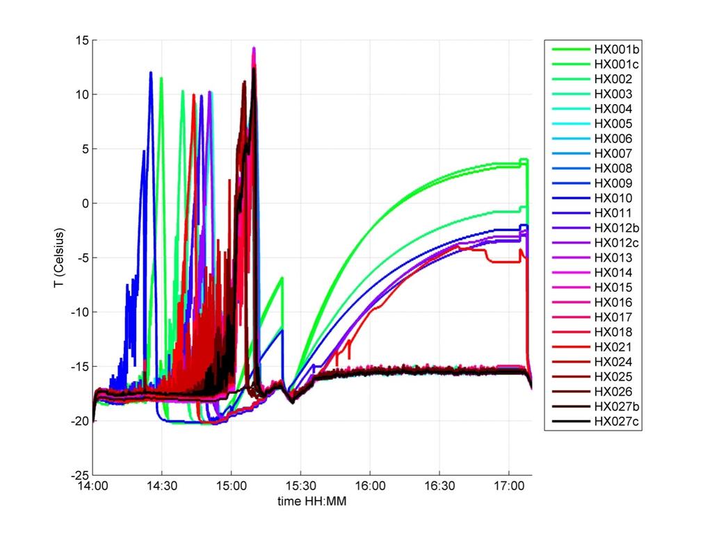
26 Figure 27: Temperature of the CO 2 evaporators versus the mass flow during the second test with a power of 25 Watt in a horizontal VELO Figure 28: Temperature of the CO 2 evaporators versus the time during the second test with a power of 25 Watt in a horizontal VELO 26
27 In the following table the mass flow is given at which a CO 2 evaporator starts to heat up. This table shows the results from the two flow reduction test at 25 Watt in a horizontal VELO C-side. Table 6: Heat up mass flow for the CO 2 evaporators of the VELO C-side in horizontal orientation powered with 25 Watt Heater-pin TX_HX... Flow 1st test (g/s) Flow 2nd test (g/s) > 5 g/s 4-5 g/s 3-4 g/s 2-3 g/s 1-2 g/s < 1 g/s Number CO 2 evaporators Figure 29: Number of CO 2 evaporators which heat up within a mass flow range at 25 Watt in a horizontal VELO 27
28 10 FLOW REDUCTION TEST WITH A POWER OF 30 WATT AND A COOLING TEMPERATURE OF -20 C IN A HORIZONTAL VELO The results of the quality tests at 30 Watt in a horizontal VELO C-side are given in this chapter. In total three tests are done, the first test with the enthalpy control on 155 J/g, the second test with the enthalpy control on 147 J/g and the third test is a fast flow reduction test, which means that power is supplied to the heaters as long as possible before the temperature interlock interrupts the test and the flow is reduced in steps every minute First flow reduction test with 30 Watt in a horizontal VELO The following results are measured at 12 November 2010, from 11:40 to 13:10. These measurements are done in a horizontal VELO at a cooling temperature of -20 C, the heater control on 155 J/g and one pump. A power of 30 Watt is applied to all heaters. The mass flow is set on 6 g/s and next in steps decreased to 0.6 g/s. Figure 30: Pressure drop over the VELO versus the mass flow during the first test with a power of 30 Watt in a horizontal VELO 28


29 Figure 31: Temperature of the CO 2 evaporators versus the mass flow during the first test with a power of 30 Watt in a horizontal VELO Figure 32: Temperature of the CO 2 evaporators versus the time during the first test with a power of 30 Watt in a horizontal VELO 29
30 10.2 Second flow reduction test with 30 Watt in a horizontal VELO The following results are measured at 12 November 2010, from 14:40 to 16:00. These measurements are done in a horizontal VELO at a cooling temperature of -20 C, the heater control on 147 J/g and one pump. A power of 30 Watt is applied to heaters 1 to 11 and 13 to 24. The mass flow is set on 6 g/s and next in steps decreased to 1.4 g/s. The following three graphs give a view of the pressure difference over the VELO C-side as a function of the mass flow, a view of the cookie temperatures versus the mass flow and the CO 2 evaporators temperatures over time. Figure 33: Pressure drop over the VELO versus the mass flow during the second test with a power of 30 Watt in a horizontal VELO 30

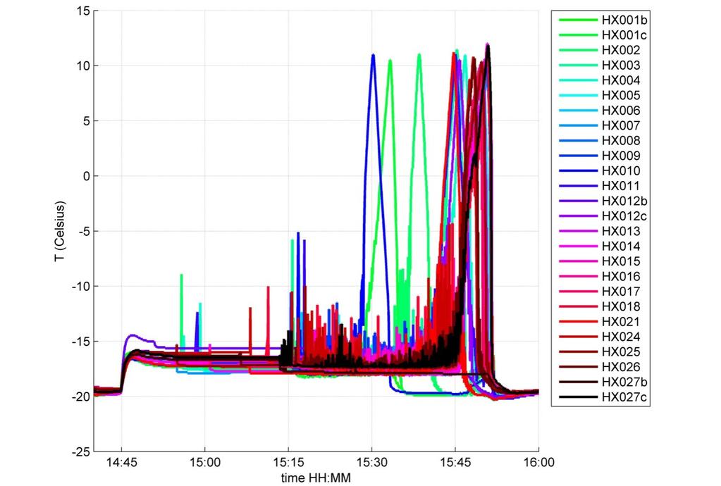
31 Figure 34: Temperature of the CO 2 evaporators versus the mass flow during the second test with a power of 30 Watt in a horizontal VELO Figure 35: Temperature of the CO 2 evaporators versus the time during the second test with a power of 30 Watt in a horizontal VELO 31
32 10.3 Fast flow reduction test with 30 Watt in a horizontal VELO The following results are measured at 12 November 2010, from 16:00 to 16:30. These measurements are done in a horizontal VELO at a cooling temperature of -20 C, the heater control on 147 J/g and one pump. A power of 30 Watt is applied to all heaters. The mass flow is set on 6 g/s and next every minute decreased in steps to 0.2 g/s. Figure 36: Pressure drop over the VELO versus the mass flow during the third test with a power of 30 Watt in a horizontal VELO 32


33 Figure 37: Temperature of the CO 2 evaporators versus the mass flow during the third test with a power of 30 Watt in a horizontal VELO Figure 38: Temperature of the CO 2 evaporators versus the time during the third test with a power of 30 Watt in a horizontal VELO 33
34 In the following table the mass flow is given at which a CO 2 evaporator starts to heat up. This table shows the results from the first, second and third flow reduction test at 30 Watt. Table 7: Heat up mass flow for the CO 2 evaporators of the VELO C-side powered with 30 Watt in a horizontal VELO Heater-pin TX_HX... Flow 1st test (g/s) Flow 2nd test (g/s) Flow 3th test (g/s) >5 g/s 4-5 g/s 3-4 g/s 2-3 g/s < 1 g/s Number CO2 evaporators Figure 39: Number of CO 2 evaporators which heat up within a mass flow range at 30 Watt in a horizontal VELO 34
35 11 HEAT UP ORDER FOR ALL CO 2 EVAPORATORS In the table below the heat up mass flows for all CO 2 evaporators are given. For the VELO C-side in vertical orientation, the heat up mass flows at a power of 15, 25 and 30 Watt are given. For the horizontal orientation of the VELO C-side the heat up mass flows at a power of 25 and 30 Watt are given. No test is done with a power of 15 Watt for the horizontal orientation of the VELO due a shortage of time. Table 8: Heat up order for all VELO C-side CO 2 evaporators Heater-pin TX_HX... Evaporator Capillary in manifold Flow (g/s) 15 Watt Flow (g/s) 25 Watt Flow (g/s) 30 Watt Flow (g/s) 25 Watt Tilted Flow (g/s) 30 Watt Tilted The order of dry-out in the capillaries for the VELO in vertical orientation is: The order of dry-out in the capillaries for the VELO in horizontal orientation is:
36 The five first capillaries that heat up in the VELO C-side are indicated in Figure 40. Vertical in trolley Horizontal as in LHCb : Spare or restricted capillary : Order of heating up Figure 40: Heat up order of the capillaries for VELO C-side 12 CONCLUSION The fluctuations in temperature, at a cooling temperature of -30 C, for all CO 2 evaporators are caused by the accumulator control. As the settings weren t correct, the primary cooling wasn t able to cool the total power of the cooling system and the heaters on the evaporators. The test done at a cooling temperature of -20 C didn t experience many fluctuations due to the accumulator control. The first CO 2 evaporators to heat up are the ones connected to the capillaries which are placed in the top part of the manifold. As the CO 2 before the manifold consists of liquid with a low vapour quality, it is possible that all the vapour, due to gravity, enters the capillaries in the top first. As the mass flow decreases, the other evaporators start to heat up. The first evaporators heat up at a mass flow range of g/s. The heat up mass flow of the evaporators is with g/s well below the total CO 2 mass flow of 10 g/s of the VTCS at CERN and the cooling capacity of the VELO C-side is sufficient. 36
DESIGN, MANUFACTURE AND TEST RESULTS OF THE VTCS CO 2 EVAPORATOR FOR THE LHCB EXPERIMENT AT CERN.
 HEFAT2010 7 th International Conference on Heat Transfer, Fluid Mechanics and Thermodynamics 19-21 July 2010 Antalya, Turkey DESIGN, MANUFACTURE AND TEST RESULTS OF THE VTCS CO 2 EVAPORATOR FOR THE LHCB
Operational aspects of the VELO cooling system of LHCb
 Operational aspects of the VELO cooling system of LHCb Eddy Jans (Nikhef) on behalf of the LHCb VELO group Introduction Main components and operation principle of the system Issues: how to prevent and
CO 2 COOLING FOR THE LHCB-VELO EXPERIMENT AT CERN.
 GL2008 8 th IIF/IIR Gustav Lorentzen Conference on Natural Working Fluids 7-10 September 2008 Copenhagen, Denmark Paper number: xxx CO 2 COOLING FOR THE LHCB-VELO EXPERIMENT AT CERN. B. Verlaat*, A. Van
PoS(Vertex 2007)009. CO 2 cooling experience (LHCb) Martin van Beuzekom, Ann Van Lysebetten 1, Bart Verlaat
009. CO 2 cooling experience (LHCb) Martin van Beuzekom, Ann Van Lysebetten 1, Bart Verlaat") CO 2 cooling experience (LHCb) Martin van Beuzekom,, Bart Verlaat Nikhef Kruislaan 409, 09 SJ Amsterdam, The Nerlands E-mail: Ann.Van.Lysebetten@cern.ch The rmal control system of LHCb Vertex LOcator (VELO)
CO 2 cooling experience (LHCb) Martin van Beuzekom,, Bart Verlaat Nikhef Kruislaan 409, 09 SJ Amsterdam, The Nerlands E-mail: Ann.Van.Lysebetten@cern.ch The rmal control system of LHCb Vertex LOcator (VELO)
TRACI, A MULTIPURPOSE CO 2 COOLING SYSTEM FOR R&D
 Paper No: GL-208 RACI, A MULIPURPOSE CO 2 COOLING SYSEM FOR R&D B. Verlaat(a,b), L. Zwalinski(b), R. Dumps(b), M. Ostrega(b,c), P. Petagna(b) and. Szwarc(b,c) (a) National Institute for Subatomic Physics
CO 2 Cooling Seminar Desy Hamburg
 bverlaat@nikhef.nl bverlaat@nikhef.nl CO 2 Cooling Seminar Desy Hamburg Bart Verlaat (Nikhef/CERN) 18 February 211 1 CO 2 Cooling Seminar The benefits of using CO 2 cooling. History of CO 2 cooling. Introduction
Safety Analysis of the 3 main parts in the CO2 system
 Safety Analysis of the 3 main parts in the CO2 system Nikhef number: Item number: Date: 11/11/2010 Page: 1 of 38 39300-MT-00001 AA1578 Status: In Work Revision: A.3 Project: Department: Mechanical Technology
A CRYOGENIC TEST STATION FOR SUBCOOLING HELIUM HEAT EXCHANGERS FOR LHC
 EUROPEAN ORGANIZATION FOR NUCLEAR RESEARCH European Laboratory for Particle Physics Large Hadron Collider Project LHC Project Report 386 A CRYOGENIC TEST STATION FOR SUBCOOLING HELIUM HEAT EXCHANGERS FOR
THE THERMOSIPHON COOLING SYSTEM OF THE ATLAS EXPERIMENT AT THE CERN LARGE HADRON COLLIDER
 THE THERMOSIPHON COOLING SYSTEM OF THE ATLAS EXPERIMENT AT THE CERN LARGE HADRON COLLIDER M. Battistin, S. Berry, A. Bitadze, P. Bonneau, J. Botelho-Direito, G. Boyd, F.Corbaz, O. Crespo-Lopez, E.Da Riva,
Development of the CMS Phase-1 Pixel Online Monitoring System and the Evolution of Pixel Leakage Current
 Development of the CMS Phase-1 Pixel Online Monitoring System and the Evolution of Pixel Leakage Current Fengwangdong Zhang On behalf of CMS Pixel Collaboration The 9th International Workshop on Semiconductor
Scientific Principals and Analytical Model. Charcoal Cooler. Lisa Crofoot MECH 425, Queens University
 Scientific Principals and Analytical Model Charcoal Cooler Lisa Crofoot MECH 425, Queens University 1.0 Scientific Principles Evaporative cooling is based on the principle that water requires heat energy
VTCS evaporator block design and prototyping. Status report July 2004
 VTCS evaporator block design and prototyping Bart Verlaat, Luc van Diepen & Martin Doets (NIKHEF) Frans Mul (VU) 30-Jul-04 bverlaat@nikhef.nl 1 VTCS evaporator block design (1) Detail of cooling block
"COP Enhancement Of Domestic Refrigerator By Sub cooling And Superheating Using Shell &Tube Type Heat Exchanger"
 "COP Enhancement Of Domestic Refrigerator By Sub cooling And Superheating Using Shell &Tube Type Heat Exchanger" 1 Prof.Gaffar G.Momin, 2 Sagar B. Tupe, 2 Swapnil A. Parate 2 Omkar G. Yewale 2 Aakash P.
CO 2 cooling for HEP experiments
 CO cooling for HEP experiments B. Verlaat, M. Van Beuzekom, A. Van ysebetten Nikhef, Kruislaan 49, 198 SJ Amsterdam, The Netherlands bverlaat@nikhef.nl Abstract The new generation silicon detectors require
Analysis of Constant Pressure and Constant Area Mixing Ejector Expansion Refrigeration System using R-1270 as Refrigerant
 Analysis of Constant Pressure and Constant Area Mixing Ejector Expansion Refrigeration System using R-1270 as Refrigerant Ravi Verma 1, Sharad Chaudhary 2 1, 2 Department of Mechanical Engineering, IET
CO2 kick-off NIKHEF - Cooling activities organization at CERN
 CO2 kick-off meeting @ NIKHEF - Cooling activities organization at CERN CERN EN/CV/DC 1 The background (1/2) The LHC Detector Cooling systems have been mainly realized at CERN. They use water or perfluorocarbons
LHCb Rich Detectors Control and High Voltage Systems
 LHCb Rich Detectors Control and High Voltage Systems Mario Sannino On behalf of LHCb RICH Group Rich 2007 Trieste 19.10.2007 1 Rich 2007 Trieste 19.10.2007 LHCb Rich Detectors Control and High Voltage
EXPERIMENTAL INVESTIGATION OF WATER COOLER SYSTEM BY USING ECO-FRIENDLY REFRIGERANT (R-134a)
") EXPERIMENTAL INVESTIGATION OF WATER COOLER SYSTEM BY USING ECO-FRIENDLY REFRIGERANT (R-134a) Abstract- With the recent government regulations, of banning the ozone depleting substances and Kyoto protocol
EXPERIMENTAL INVESTIGATION OF WATER COOLER SYSTEM BY USING ECO-FRIENDLY REFRIGERANT (R-134a) Abstract- With the recent government regulations, of banning the ozone depleting substances and Kyoto protocol
The Compact Muon Solenoid Experiment. Conference Report. Mailing address: CMS CERN, CH-1211 GENEVA 23, Switzerland
 Available on CMS information server CMS CR -2016/298 The Compact Muon Solenoid Experiment Conference Report Mailing address: CMS CERN, CH-1211 GENEVA 23, Switzerland 28 October 2016 (v2, 25 November 2016)
Towards a Detector Control System for the ATLAS Pixeldetector
 Towards a Detector Control System for the ATLAS Pixeldetector Pixel2002, Carmel September 2002 Overview of the Detector Control System The Front End System The Back End System Experience with the Testbeam
Maluna Unhinged vs Yeti Tundra Thermal Performance Comparison January 2017
 Maluna Unhinged vs Yeti Tundra Thermal Performance Comparison January 2017 Abstract A Maluna Unhinged cooler was tested and measured for performance relative to a Yeti Tundra cooler. Three identical tests
Performance Analysis of a Domestic Refrigerator in Malaysia using Experimental Method
 erformance Analysis of a Domestic Refrigerator in Malaysia using Experimental Method M.Y. aib 1, M. S. M. Sani 2, M. M. Noor 3, K. Kadirgama 4 Faculty of Mech. Engineering Universiti Malaysia ahang un
Heat Pump Fluidised Bed Dryer with CO 2 as Refrigerant Measurements of COP and SMER
 Heat Pump Fluidised Bed Dryer with CO 2 as Refrigerant Measurements of COP and SMER Trygve M. Eikevik, Ingvald Strømmen, Odilio Alves-Filho Norwegian University of Science and Technology (NTNU) Department
Experimental Study on Match for Indoor and Outdoor Heat Exchanger of Residential Airconditioner
 Purdue University Purdue e-pubs International Refrigeration and Air Conditioning Conference School of Mechanical Engineering 2014 Experimental Study on Match for Indoor and Outdoor Heat Exchanger of Residential
Experimental Investigation of a Hybrid Evacuated Tube Solar Collector
 International Conference on Mechanical, Industrial and Materials Engineering 2015 (ICMIME2015) 11-13 December, 2015, RUET, Rajshahi, Bangladesh Paper ID: ET-46 Experimental Investigation of a Hybrid Evacuated
STUDY ON THE CONTROL ALGORITHM OF THE HEAT PUMP SYSTEM FOR LOAD CHANGE
 Numbers of Abstract/Session (given by NOC) - 1 - STUDY ON THE CONTROL ALGORITHM OF THE HEAT PUMP SYSTEM FOR LOAD CHANGE Seok Ho Yoon, Kong Hoon Lee, Chan Ho Song, and Ook Joong Kim Environment and Energy
Pocket Dilution Cooler
 Pocket Dilution Cooler T. Prouvé, N. Luchier, L. Duband CEA/DSM/INAC/SBT Grenoble, 38054 Cedex 9, France ABSTRACT We have developed a compact, self-contained dilution cooler that can be operated from a
A Treatise on Liquid Subcooling
 A Treatise on Liquid Subcooling While the subject of this article is Liquid Refrigerant Subcooling, its affect on the operation of the thermostatic expansion valve (TEV), and ultimately on system performance
2 Overview of the Pixel Detector Control System
 Towards a Detector Control System for the ATLAS Pixel Detector S. Kersten, K.H. Becks, M. Imhäuser, P. Kind, P. Mättig, J. Schultes Fachbereich Physik Bergische Universität D-4097 Wuppertal 1 Abstract
Performance Evaluation of R290 as Substitution to R22 & Mixture of Them in Vapour Compression Refrigeration System
 Performance Evaluation of R29 as Substitution to & Mixture of Them in Vapour Compression System Pawan Kumar Mishra #1, Amol Tripathi *2 #RIT Department of Mechanical Engineering Department, RGPV,Bhopal
Performance Evaluation of R290 as Substitution to R22 & Mixture of Them in Vapour Compression Refrigeration System
 Performance Evaluation of R290 as Substitution to R22 & Mixture of Them in Vapour Compression Refrigeration System Pawan Kumar Mishra #1, Amol Tripathi *2 # RIT Department of Mechanical Engineering Department,
EFFECT OF PAG OIL CIRCULATION RATE ON THE HEAT TRANSFER PERFORMANCE OF AIR-COOLED HEAT EXCHANGER IN CARBON DIOXIDE HEAT PUMP SYSTEM
 - 1 - EFFECT OF PAG OIL CIRCULATION RATE ON THE HEAT TRANSFER PERFORMANCE OF AIR-COOLED HEAT EXCHANGER IN CARBON DIOXIDE HEAT PUMP SYSTEM Shun YOSHIOKA, Hyunyoung KIM, Kazushige KASAI, Daikin Industries,
Aging Analysis of Micromegas Detectors for ATLAS New Small Wheel
 Aging Analysis of Micromegas Detectors for ATLAS New Small Wheel Melissa Quinnan August 15, 2015 Supervisor: Michele Bianco Abstract In preparation for the coming High Luminosity Large Hadron Collider
Comparative Performance of HFO Blends in a Condenser
 The knowledge hub for refrigeration, air conditioning and heat pumps Nick Atkins MInstR Simon Jones MInstR Gary Bell Comparative Performance of HFO Blends in a Condenser Paper 2 research laboratory tests
Status of the LHCb Detector. LHCC Open Session CERN, 27 November 2002 Werner Witzeling on behalf of the LHCb Collaboration
 Status of the LHCb Detector LHCC Open Session CERN, 27 November 2002 Werner Witzeling on behalf of the LHCb Collaboration Content Vertex Locator Magnet Outer Tracker RICH2 Calorimeters Muon Detector Online
COMPACT HEAT EXCHANGERS FOR MOBILE CO 2 SYSTEMS
 COMPACT HEAT EXCHANGERS FOR MOBILE CO 2 SYSTEMS A. Hafner SINTEF Energy Research Refrigeration and Air Conditioning Trondheim (Norway) ABSTRACT The natural refrigerant carbon dioxide (CO 2 ) with all its
SPECIFICATIONS MODEL E859C MINI DEHYDRATOR
 SPECIFICATIONS MODEL E859C MINI DEHYDRATOR 1 DEHYDRATION TECHNOLOGY This proposal describes the equipment which shall be supplied by ENERVAC for a system for processing (dehydrating, de-aerating, purifying
IJIRST International Journal for Innovative Research in Science & Technology Volume 1 Issue 12 May 2015 ISSN (online):
:") IJIRST International Journal for Innovative Research in Science & Technology Volume 1 Issue 12 May 2015 ISSN (online): 2349-6010 Githin V Sam Jethin Babu Jesvin Sam Jithin Victor Abstract Loop heat pipes
IJIRST International Journal for Innovative Research in Science & Technology Volume 1 Issue 12 May 2015 ISSN (online): 2349-6010 Githin V Sam Jethin Babu Jesvin Sam Jithin Victor Abstract Loop heat pipes
(Refer Slide Time: 00:00:40 min)
") Refrigeration and Air Conditioning Prof. M. Ramgopal Department of Mechanical Engineering Indian Institute of Technology, Kharagpur Lecture No. # 10 Vapour Compression Refrigeration Systems (Refer Slide
Refrigeration and Air Conditioning Prof. M. Ramgopal Department of Mechanical Engineering Indian Institute of Technology, Kharagpur Lecture No. # 10 Vapour Compression Refrigeration Systems (Refer Slide
Modeling And Testing Of R23/R134a Mixed Refrigerant System With Water Cooled Separator For Low Temperature Refrigeration
 Marquette University e-publications@marquette Master's Theses (2009 -) Dissertations, Theses, and Professional Projects Modeling And Testing Of R23/R134a Mixed Refrigerant System With Water Cooled Separator
15. Heat Pipes in Electronics (1)
") 15.1 Components of a Heat Pipe The three basic components of a heat pipe are: 15. Heat Pipes in Electronics (1) 15.1.1 The Container The function of the container is to isolate the working fluid from the
15.1 Components of a Heat Pipe The three basic components of a heat pipe are: 15. Heat Pipes in Electronics (1) 15.1.1 The Container The function of the container is to isolate the working fluid from the
CASE STUDY REGARDING ENERGY EFFICIENCY OF A VENTILATION SYSTEM WITH RECUPERATIVE HEAT RECOVERY
 JOURNAL OF APPLIED ENGINEERING SCIENCES Article Number: 131_VOL.3(16), issue 2_2013, pp.27-32 ISSN 2247 3769 ISSN-L 2247 3769 (Print) / e-issn 2284-7197 CASE STUDY REGARDING ENERGY EFFICIENCY OF A VENTILATION
Enhancement of COP by Using Spiral and Microchannel Condenser instead of conventional Condenser of VCR System
 Enhancement of COP by Using Spiral and Microchannel instead of conventional of VCR System 1 P.G. Lohote, 2 Dr.K.P. Kolhe. 1 P.G. Student, 2 Professor. 1,2 Department of Mechanical Engineering, JSPM s,
Heat pump and energy recovery systems
 SBS5311 HVACR II http://ibse.hk/sbs5311/ Heat pump and energy recovery systems Ir. Dr. Sam C. M. Hui Faculty of Science and Technology E-mail: cmhui@vtc.edu.hk Oct 2017 Contents Basic concepts Air-to-air
Experimental investigation of Hybrid Nanofluid on wickless heat pipe heat exchanger thermal performance
 Experimental investigation of Hybrid Nanofluid on wickless heat pipe heat exchanger thermal performance #1 Jaydev S. Bade, #2 Dr. Nitin U. Korde 1 Department of Mechanical Engineering, Savitribai Phule
DROP-IN EVALUATION OF REFRIGERANT 1234YF IN A RESIDENTIAL INTEGRAL HEAT PUMP WATER HEATER
 Numbers of Abstract/Session (given by NOC) - 1 - DROP-IN EVALUATION OF REFRIGERANT 1234YF IN A RESIDENTIAL INTEGRAL HEAT PUMP WATER HEATER Richard W. Murphy Van D. Baxter Edward A. Vineyard Randall L.
SOLAR PARABOLIC COLLECTOR ASSISTED EVAPORATIVE COOLING SYSTEM
 2 nd International Conference on Energy Systems and Technologies 18 21 Feb. 2013, Cairo, Egypt SOLAR PARABOLIC COLLECTOR ASSISTED EVAPORATIVE COOLING SYSTEM Tanuja Sheorey 1 +, Vandana Arora 1 1 PDPM Indian
PERFORMANCE OF DEEP FREEZER BY USING HYDROCARBON BLENDS AS REFRIGERANTS
 Int. J. Chem. Sci.: 14(S2), 2016, 665-674 ISSN 0972-768X www.sadgurupublications.com PERFORMANCE OF DEEP FREEZER BY USING HYDROCARBON BLENDS AS REFRIGERANTS J. THAVAMANI *, MARRIPUDAGALA KOMALI, SHAIK
Department of MCE, Islamic University of Technology 2. Abstract
 Paper ID: TE-85 Study of power consumption characteristics of LPG and R134a in a vapor compression refrigeration system Md. Abu Shaid Sujon 1, Rakibul Hossain Ahmed 2, Dr. A.K.M. Sadrul Islam 3, Sk. Suzauddin
CHAPTER I INTRODUCTION. In the modern life, electronic equipments have made their way
 1 CHAPTER I INTRODUCTION In the modern life, electronic equipments have made their way in to practically every part, which is from electronic gadgets to high power computers. Electronic components have
ASSESSMENT OF R430A REFRIGERANT AS A POSSIBLE SUBSTITUTE TO R134A REFRIGERANT IN LARGE CAPACITY FREEZER
 University of Maiduguri Faculty of Engineering Seminar Series Volume 6, december 5 ASSESSMENT OF REFRIGERANT AS A POSSIBLE SUBSTITUTE TO R34A REFRIGERANT IN LARGE CAPACITY FREEZER S. Shodiya*, M.B. Oumarou
Air Liquide Advanced Technologies Division Sassenage, 38360, France
 Published in AIP Conference Proceedings 1218, pp. 1476-1483 (2010) OPERATION RESULTS OF THE KSTAR HELIUM REFRIGERATION SYSTEM H.- S. Chang1, E. Fauve2, D.-S. Park1, J.-J. Joo1, K.-M. Moon1, K.-W. Cho1,
Measured Performance of Four New 18 K Helium Refrigerators for the LHC Cryogenic System
 EUROPEAN ORGANIZATION FOR NUCLEAR RESEARCH European Laboratory for Particle Physics Large Hadron Collider Project LHC Project Report 796 Measured Performance of Four New 18 kw@4.5 K Helium Refrigerators
THERMOSYS 4.3. Getting Started Guide
 THERMOSYS 4.3 Getting Started Guide February 2016 Table of Contents 1 Installation and File Organization... 3 2 THERMOSYS by Example... 4 2.1 THERMOSYS Component Descriptions... 5 2.1.1 Compressor... 6
Understanding total measurement uncertainty in power meters and detectors
 Understanding total measurement uncertainty in power meters and detectors Jay Jeong, MKS Instruments. Inc. INTRODUCTION It is important that users of calibrated power meters and detectors understand and
Heated tools. Semiconductor equipment
 Heated tools Semiconductor equipment Ceramic heating elements made of silicon nitride and aluminum nitride can be manufactured as tools in various shapes. The heating function can be integrated in complex
Heat Exchanger. The purpose may be either to remove heat from a fluid or to add heat to a fluid.
 HEAT EXCHANGERS Heat Exchanger Heat exchanger is an apparatus or an equipment in which the process of heating or cooling occurs. The heat is transferred from one fluid being heated to another fluid being
High Temperature Water-Titanium Heat Pipes for Spacecraft Fission Power
 High Temperature Water-Titanium Heat Pipes for Spacecraft Fission Power Rebecca Hay 1 and William G. Anderson 1 1 Advanced Cooling Technologies, 1046 New Holland Ave. Lancaster, PA 17601 717-295-6104;
Heat sinks for electronic cooling applications
 Heat sinks for electronic cooling applications Shubhash V. Jadhav Department of Mechanical Engineering, SVERI s College of Engineering Pandharpur, Introduction The previous century brought the miniaturization
Aging measurements on triple-gem detectors operated with CF 4 based gas mixtures
 IEEE, Roma, October 2004 Aging measurements on triple-gem detectors operated with CF 4 based gas mixtures M. Alfonsi 1, G. Bencivenni 1, W. Bonivento 2,A.Cardini 2, P. de Simone 1, F.Murtas 1, D. Pinci
Transcritical CO2 Bottle Cooler Development
 Transcritical CO2 Bottle Cooler Development C. Rohrer Ingersoll Rand Climate Control, 12999 St. Charles Rock Rd. Bridgeton, MO, United States 314 298-4765, clay_rohrer@irco.com ABSTRACT This paper contains
Section 9. Comparing Energy Consumption: More for Your Money. What Do You See? What Do You Think? Investigate. Learning Outcomes
 Section 9 Comparing Energy Consumption: More for Your Money Section 9 Comparing Energy Consumption: More for Your Money What Do You See? Learning Outcomes In this section, you will Measure and compare
Available online at ScienceDirect. Energy Procedia 91 (2016 ) 35 41
 35 41") Available online at www.sciencedirect.com ScienceDirect Energy Procedia 91 (216 ) 35 41 SHC 215, International Conference on Solar Heating and Cooling for Buildings and Industry Butane heat pipes for stagnation
Available online at www.sciencedirect.com ScienceDirect Energy Procedia 91 (216 ) 35 41 SHC 215, International Conference on Solar Heating and Cooling for Buildings and Industry Butane heat pipes for stagnation
Operation of a Two-Phase Reverse Loop Thermosyphon
 Journal of Applied Science and Engineering, Vol. 18, No. 3, pp. 259 264 (2015) DOI: 10.6180/jase.2015.18.3.06 Operation of a Two-Phase Reverse Loop Thermosyphon Meng-Chang Tsai 1, Shung-Wen Kang 2 *, Heng-Yi
Effects of Oil on atranscritical Carbon Dioxide Air Conditioning Systems some experiences -
 Purdue University Purdue e-pubs International Refrigeration and Air Conditioning Conference School of Mechanical Engineering 2006 Effects of Oil on atranscritical Carbon Dioxide Air Conditioning Systems
Experimental performance evaluation of heat pump by using CO 2. as a refrigerant. IOP Conference Series: Materials Science and Engineering
 IOP Conference Series: Materials Science and Engineering PAPER OPEN ACCESS Experimental performance evaluation of heat pump by using CO 2 as a refrigerant To cite this article: V K Venkatesh et al 2016
Performance Evaluation of Eco- Friendly Alternate Refrigerants for VCRS
 Performance Evaluation of Eco- Friendly Alternate Refrigerants for VCRS Lalit Narayan, Abhishek Arya 2,2 M. Tech. Scholar, Associate Professor,,2 Scope College of Engineering, Bhopal, India Abstract: The
International Journal of Engineering Research (IJOER) [Vol-1, Issue-3, June- 2015]
![International Journal of Engineering Research (IJOER) [Vol-1, Issue-3, June- 2015]](/thumbs/86/93674748.jpg "International Journal of Engineering Research (IJOER) [Vol-1, Issue-3, June- 2015]") Experimental Investigation To Develop The Refrigeration System With Two Phases Condensing Ejector Along With Energy Saving Anjani Kumar 1, Kuldip Kumar 2, Ujjwal Kumar Nayak 3 123 Department of mechanical
Experimental Investigation To Develop The Refrigeration System With Two Phases Condensing Ejector Along With Energy Saving Anjani Kumar 1, Kuldip Kumar 2, Ujjwal Kumar Nayak 3 123 Department of mechanical
Thermodynamic analysis of air cycle refrigeration system for Chinese train air conditioning
 Available online at www.sciencedirect.com Systems Engineering Procedia () 6 International Conference on Risk and Engineering Management (REM) Thermodynamic analysis of air cycle refrigeration system for
Application Engineering
 Revised September, 2006 ECONOMIZED VAPOR INJECTION (EVI) COMPRESSORS INDEX SECTION PAGE 1. Introduction... 1 2. Theory of Operation... 1 3. Nomenclature... 3 4. ARI Low Temperature Ratings... 3 5. Approved
Effects of Non-Uniform Refrigerant and Air Flow Distributions on Finned- Tube Evaporator Performance
 Effects of Non-Uniform Refrigerant and Air Flow Distributions on Finned- Tube Evaporator Performance Jong Min Choi, W. Vance Payne and Piotr A. Domanski National Institute of Standards and Technology Building
Methods of Testing Capacity of Refrigerant Solenoid Valves
 BSR/ASHRAE Standard 158.1-2012R Public Review Draft Methods of Testing Capacity of Refrigerant Solenoid Valves First Public Review (November 2018) (Complete Draft for Full Review) This draft has been recommended
Fire Protection Scover
 November 2nd, 2011 2e version Fire Protection Scover Testing Fire Protection of a small storage facility for vehicles for handicapped transport based on certification scheme BRL-K23003. Fire Protection
CHAPTER 7 PERFORMANCE ANALYSIS OF VAPOUR COMPRESSION REFRIGERATION SYSTEM IN HYBRID REFRIGERATION SYSTEM
 111 CHAPTER 7 PERFORMANCE ANALYSIS OF VAPOUR COMPRESSION REFRIGERATION SYSTEM IN HYBRID REFRIGERATION SYSTEM 7.1 INTRODUCTION Energy is the primary component to run any system in the world. According to
The LHCb Outer Tracker: Production & Ageing studies
 The LHCb Outer Tracker: Production & Ageing studies Kaffeepalaver MPI-K Physikalisches Institut Physikalisches Institut 1 LHC at CERN p-p collisions beam energy 7 TeV 8.6km Four experiments: Atlas, CMS,
Performance Enhancement of Refrigeration Cycle by Employing a Heat Exchanger
 Performance Enhancement of Refrigeration Cycle by Employing a Heat Exchanger Shoeb Inamdar 1, H. S. Farkade 2 P.G. Student, Department of Mechanical Engineering, Govt. College of Engg. Amravati. Maharashtra,
Air-Cooling Evaporators
 Air-Cooling Evaporators Types of construction Circuit Configurations Methods of Refrigerant Feed Methods of Air Circulation Methods of Defrost Type of Construction Bare tube Finned Tube Plate-surface Bare
Determination of the enthalpy of vaporization of liquids
 Related concepts Enthalpy of vaporization, enthalpy of condensation, enthalpy of sublimation, vapour pressure, entropy of vaporization, Clapeyron-Clausius equation, Trouton s rule, laws of thermodynamics,
Reheating Refrigeration System
 Vol.2, Issue.1, Jan-Feb 2012 pp-271-275 ISSN: 2249-6645 Reheating Refrigeration System Meemo Prasad Assistant Engineer, SEPCO1 Abstract The title Reheating Refrigeration System has the objective to utilize
Thermal Performance of a Loop Thermosyphon
 Tamkang Journal of Science and Engineering, Vol. 13, No. 3, pp. 281 288 (2010) 281 Thermal Performance of a Loop Thermosyphon Shung-Wen Kang*, Meng-Chang Tsai, Chih-Sheng Hsieh and Jian-You Chen Department
Adhesive Test Program
 Adhesive Test Program Claudia Gemme / INFN - Genova Adhesives needed to assembly a module Status of each adhesive To do list C. Gemme University and INFN / Genova Pixel week, Cern, Dec 6th 2001 Module
Exciting Swiss temperature control technology, distributed in North America exclusively by...
 Exciting Swiss temperature control technology, distributed in North America exclusively by... TM North America Frigel North America, Inc. 150 Prairie Lake Rd, Unit A East Dundee, IL. 60118 USA Tel (847)
Thermodynamic Calculations of Two-Stage Vapor Compression Refrigeration Cycle with Flash Chamber and Separate Vapor Mixing Intercooler
 Thermodynamic Calculations of Two-Stage Vapor Compression Refrigeration Cycle with Flash Chamber and Separate Vapor Mixing Intercooler Author: Volodymyr Voloshchuk Vl.volodya@gmail.com Introduction In
ME 354 THERMODYNAMICS LAB THE REFRIGERATION CYCLE
 Due date for write-up: March 2, 2012 1 ME 354 THERMODYNAMICS LAB THE REFRIGERATION CYCLE INTRODUCTION: The attached figure shows schematically the refrigeration unit located in the Heat Transfer Lab, E3-2108.
Thick-Film Heater achieves Superior Performance in Thermal Response, Uniformity and Efficiency.
 Thick-Film Heater achieves Superior Performance in Thermal Response, Uniformity and Efficiency. by Mary Ruggiero, P.Eng., PhD and John Stockton, P.Eng Abstract IntegrAL thick-film heaters by Datec Corporation
IR-REVERSIBILITY ANALYSIS OF A SPLIT TYPE AIRCONDITIONER USING R600a AS REFRIGERANT
 Proceedings of the International Conference on Mechanical Engineering and Renewable Energy 217 (ICMERE217) 18 2 December, 217, Chittagong, Bangladesh ICMERE217-PI-48 IR-REVERSIBILITY ANALYSIS OF A SPLIT
Electric radiator tests
 Electric radiator tests Carried out for Haverland By P Stonard 16 July 2010 Electric radiator tests Carried out for: Haverland Avda San Martin De Valdeigiesias Km-2,200 Alcorcon MADRID 28925 Spain Contract:
SERVICE MANUAL REFRIGERATION
 SERVICE MANUAL REFRIGERATION ELECTROLUX HOME PRODUCTS S.p.A. Publication no. Spares Operations Italy 599 37 75-07 Corso Lino Zanussi, 30 060824 I - 33080 PORCIA / PN (ITALY) ITZ/SERVICE/AA Fax +39 0434
CHAPTER 1 INTRODUCTION
 CHAPTER 1 INTRODUCTION 1.1 CFC REFRIGERANTS Since the 1930s, chlorofluorocarbons (CFCs) have been widely used as foam blowing agents, aerosols and especially refrigerants due to their pre-eminent properties
Numerical Stability Analysis of a Natural Circulation Steam Generator with a Non-uniform Heating Profile over the tube length
 Numerical Stability Analysis of a Natural Circulation Steam Generator with a Non-uniform Heating Profile over the tube length HEIMO WALTER Institute for Thermodynamics and Energy Conversion Vienna University
Cost-Effective COP Enhancement of a Domestic Air Cooled Refrigerator using R-134a Refrigerant
 Cost-Effective COP Enhancement of a Domestic Air Cooled Refrigerator using R-134a Refrigerant Tarang Agarwal 1, Manoj Kumar 2, Praveen Kumar Gautam 3 1,2,3 Assistant Professor, Department of Mechanical
A Comparison Between Refrigerants Used In Air Conditioning
 A Comparison Between Refrigerants Used In Air Conditioning Derya Özkan, Özden Agra and Özlem Çetin University of Yildiz Technical University, Turkey Corresponding email: tumer@yildiz.edu.tr SUMMARY It
INFLUENCE OF REFRIGERANT CHARGE AND AIR INLET TEMPERATURES ON THE PERFORMANCE OF AN AUTOMOTIVE AIR CONDITIONING SYSTEM
 ID:613 INFLUENCE OF REFRIGERANT CHARGE AND AIR INLET TEMPERATURES ON THE PERFORMANCE OF AN AUTOMOTIVE AIR CONDITIONING SYSTEM Mario H. MACAGNAN (*), Jacqueline B. COPETTI (**) LETEF, Universidade do Vale
LMM-H03 Mass Air FLow Sensor
 Mass Air FLow Sensor Product Description LMM-H03 is a thermodynamic sensing element for the bidirectional measurement of mass air flow in a well defined channel. It is dedicated for applications with high
Application of two hybrid control methods of expansion valves and vapor injected compression to heat pumps
 AM-4249223-1 - Application of two hybrid control methods of expansion valves and vapor injected compression to heat pumps Christian K. Bach, Graduate Student, Eckhard A. Groll, Reilly Professor, James
January 16 th, 2014 New York City
 Compressor Calorimeter Test of R-404A Alternative Refrigerants ARM-31a, D2Y-65, L-40, and R-32/R- 134a (50/50) in Medium Temperature Refrigeration Scroll Compressor Som Shrestha Omar Abdelaziz January
COMPACT ADSORPTION CHILLERS WITH COATED ADSORBER HEAT EXCHANGERS
 - 1 - COMPACT ADSORPTION CHILLERS WITH COATED ADSORBER HEAT EXCHANGERS W. Mittelbach, Managing Director, SorTech AG, Weinbergweg 23, 06120 Halle, Germany T. Büttner, Head of R&D / production, SorTech AG,
Last exam / sista tent
 Värme- och strömningsteknik Thermal and flow engineering Refrigeration Kylteknik Ron Zevenhoven Exam 24-2-2017 4 questions, max. points = 8 + 8 + 6 + 8 = 30 All support material is allowed except for telecommunication
Air-Cooled Thermosyphon for Press-Pack Stack of Semiconductors
 Journal of Physics: Conference Series PAPER OPEN ACCESS Air-Cooled Thermosyphon for Press-Pack Stack of Semiconductors To cite this article: M. Habert and B. Agostini 2016 J. Phys.: Conf. Ser. 745 032110
Optimization of key processes in a refrigeration system. For maximum cooling load there was an EER increase of 18,6% (EER = Energy efficiency Ratio).
.") New Sensor Technologies Control phase of Refrigerant, made Ammonia more Safe and Optimizing all type of Refrigeration systems, work with NH3, CO2, Propan, HFC/HFO Refrigerant Information, experiences and
New Sensor Technologies Control phase of Refrigerant, made Ammonia more Safe and Optimizing all type of Refrigeration systems, work with NH3, CO2, Propan, HFC/HFO Refrigerant Information, experiences and