INSTALLATION AND OPERATION MANUAL MODEL TR70\TR130\TR200\TR300 TOTAL RECOVERY FOR ALL CLIMATES (TR)
|
|
|
- Alexina Hardy
- 6 years ago
- Views:
Transcription
 2 233 900, Fax 52 (222) 223 3914, www.soler-palau.com.")

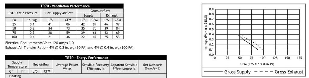
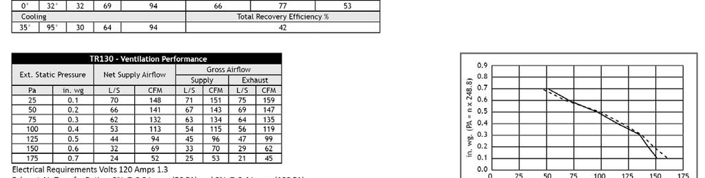
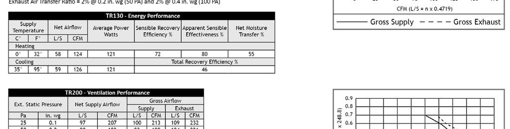
1 Soler & Palau USA: Tel (800) , Fax (800) , Canada: Tel (866) , Fax (866) , Mexico: Tel 52 (222) , Fax 52 (222) , INSTALLATION AND OPERATION MANUAL MODEL TR70\TR130\TR200\TR300 TOTAL RECOVERY FOR ALL CLIMATES (TR) TR130 (door closed) TR130 (door open) WARNING RISK OF FIRE, ELECTRIC SHOCK, OR INJURY. OBSERVE ALL CODES AND THE FOLLOWING: 1. Before servicing or cleaning the unit, unplug the unit line cord. Make sure unit is not running before opening its door. 2. This installation manual shows the suggested installation method. Additional measures may be required by local codes and standards. 3. Installation work and electrical wiring must be done by qualified professional(s) in accordance with all applicable codes, standards and licensing requirements. 4. Any structural alterations necessary for installation must comply with all applicable building, health, and safety code requirements. 5. Connect this unit only to a 120VAC grounded receptacle protected by a 15 or 20 amp circuit breaker. Do not remove the unit s line cord. 6. Do not install unit or controls where they can be reached from a tub or shower. 7. This unit must be properly ducted to the outdoors. 8. Outside air inlet for this unit must be located away from sources of hazardous air such as auto exhausts. 9. Sufficient air is needed for proper combustion and exhausting of gases through the flue (chimney) of fuel burning equipment that might be installed in the area affected by this equipment. If this unit is exhausting air from a space in which chimney-vented fuel burning equipment is located, take steps to assure that combustion air supply is not affected. Follow the heating equipment manufacturer s requirements and the combustion air supply requirements of applicable codes and standards. 10. This unit is intended for general ventilating only. Do not use to exhaust hazardous or explosive materials and vapors. Do not connect this unit to range hoods, fume hoods or collection systems for toxics. 11. When cutting or drilling into wall or ceiling, do not damage electrical wiring and other hidden utilities. 12. Use the unit only in the manner intended by the manufacturer. If you have questions, contact the manufacturer. 1. To avoid motor bearing damage and noisy and/or unbalanced impellers, keep drywall spray, construction dust, etc., out of the unit. 2. Do not connect power to the units external control terminals: this will damage the unit. The external terminals are for use only with un-powered controls designed for low-voltage operation. TR70_130_200_300Man_JULY10.doc _000 Revised 07/ Soler & Palau Page 1
2 SYSTEM LAYOUT Before you begin Read all instructions before installing the unit. Also review supplemental instructions included with any controls that will be installed. Carefully unpack and inspect the unit for shipping damage. Open the access door and inspect inside the unit. Attach the four duct collars to the unit with the screws provided in the plastic small-parts bag. Location of the Unit Select a location so that: The fresh air intake vent from the outside is placed a minimum of ten feet from any other exhaust vent, and is at least 30 long. The two ducts to the outside are as short and straight as possible, for the best performance from the system. Shorter duct runs help assure that the system is balanced: the amount of air brought in is equal to the amount of air exhausted. The power cord reaches an electrical outlet. The door can be opened to allow cleaning the core and filters. Provide at least 24 of clearance at front of unit for service access to the blowers, filters and energy exchange core. The exhaust outlet and fresh air inlet on the outside of the building should be at least ten feet apart to avoid crosscontamination. The exhaust duct should be about the same length as the fresh air duct. The exhaust outlet should not dump air into an enclosed space or into any other structure. Do not install the exhaust outlet and fresh air inlet through the roof or roof soffit. If these are the only available options call S&P technical support for help. The preferred mounting location for the unit is on a concrete foundation wall because the foundation wall will isolate any blower vibration. If a basement area is not available or practical, use other mechanical room space such as a closet, garage, storage, or accessible attic or crawl space. NOTE: If you wish to install the unit in an attic or other unconditioned space, you must insulate all of the unit s ductwork that is located in the attic. Use at least R-6 insulation. (A) Separate Room Air Pick-up Fresh Air to Furnace Return Air Trunkline Separate Return Air and Fresh Air Supply FA Living area* SA (B) OA EA ERV TR FA SA OA EA TR ERV RA (from bathrooms, dining area) RA (Furnace) Minimum 3' Furnace RA (from bathrooms, kitchen area) RA (Furnace) Furnace (C) Note: TR Blower may be operated separate from Furnace Blower Furnace Return Air Back Into Return Air Note: TR Blower may be operated separate from Furnace Blower *Use caution to introduce FA at low velocity and where good mixing will occur to minimize discomfort from drafts Furnace Return Air Into Furnace Supply Air Install internal elbow here (D) OA EA ERV TR Minimum 3' FA SA OA EA ERV TR FA SA Minimum 3' RA RA (to (to ERV) TR) RA (Furnace) Minimum 3' Furnace RA (to (to TR) ERV) RA (Furnace) Furnace Note: The Furnace Blower must be operated any time the TR is operated. Use furnace fan on continuous low speed or optional SFM control to cycle furnace fan on with TR Minimum 3' Note: TR Blower may be operated separate from Furnace Blower RA: Room Air OA: Outside Air FA: Fresh Air EA: Exhaust Air SA: Supply Air (furnace) TR70_130_200_300Man_JULY10.doc _000 Revised 07/ Soler & Palau Page 2
3 SYSTEM LAYOUT Exhaust & Outside Air Ducts The Exhaust Air Duct and the Outside Air Duct connect the unit to the outside. Flexible insulated duct is typically used. See Table under Duct Sizes, below Inside Ductwork System For houses without ducted heating or cooling systems see Schematic (B): In most houses one or two fresh air grilles in a central part of the house provide effective distribution of the fresh air into the home, particularly when the stale exhaust air is picked up at several points. Because the fresh air is usually somewhat cooler than the household air, the fresh air supply grilles should be located in a traffic area like a hallway or stairway rather than in a sitting area. If you want to get fresh air into specific rooms with high occupancy, you can split up the fresh air supply. For houses with forced-air heating and cooling systems see Schematics (A), (C) and (D): Most units are installed with the fresh air duct connected directly to a return duct for the main heating and cooling system. Be careful to connect the fresh air duct at least three feet from the return plenum to minimize suction from the furnace blower. A connection closer to the furnace may result in unbalanced flow and associated problems. For installations that collect stale air from specific rooms in the home for example, Schematics (A) and (B): Locate stale air return grilles (RA) in rooms where moisture and odors are generated: bathrooms, the kitchen, and perhaps other areas where contaminants are generated such as in the home workshop. Return grilles in these other areas may be dampered so that they can be shut off when not in use. A central location such as a hallway is also acceptable but won't clear humidity and odors from baths and kitchens as rapidly. Locate stale air return grilles (RA) near the ceiling on inside walls. Stale air returns are usually easiest to install in interior partitions. Put them in the ceiling if that is easier. Stale Air Return Grille Sizes (8 round on TR300) Bathroom 4" X 10" or 6" X 10" - 40 to 60 sq. in. Kitchen 6" X 10" or 60 sq. in. DO NOT PLACE ANY STALE AIR RETURNS IN GARAGES. Can a TR be used to ventilate bathrooms? A S&P TRV can be used as a central exhaust system in place of bathroom exhaust fans. Tie a grille in each bathroom directly back to the TR see Schematic (A). A successful installation should provide at least 50 CFM of exhaust per moisture producing bathroom. When used for bathroom exhaust, the TR70 should be used for only one bathroom, the TR130 should be used for no more than two bathrooms, the TR200 for up to four bathrooms and the TR300 for up to six bathrooms. Install a control in each bathroom ventilated by the TR (see Secondary Operating Controls, below). For houses where radon is a concern: The first line of defense against radon should always be techniques that prevent the entry of radon into the home, such as under-slab suction, vented perimeter drainage, and crack sealing. However, if moderate levels of radon continue to be present, it is important that the unit slightly pressurize the basement, not de-pressurize the basement. Installation of this unit for radon mitigation is beyond the scope of this manual. Consult a radon mitigation professional. Duct Sizes Duct Minimum Sizes and Type Exhaust Air & Outside Air (EA & OA) Fresh Air & Stale Air (FA & RA) 6" round insulated duct (8 round for TR300) 8 round insulated duct may be used to maintain maximum airflow 6" round or 8" oval rigid un-insulated All ducts from unit to house in unconditioned spaces like attics and crawl spaces MUST BE INSULATED. Controls For an installation in which the TR should run continuously in order to provide the required ventilation rate for the home, no controls are needed. However, in most installations, control over the unit operation is desired and this is best provided by a Proportional Timer. A Dehumidistat is another option but works properly only during the heating season. If the TR is used during the summer, a Proportional Timer should also be installed. Proportional timers (SPTL or SFM controls) may be located anywhere that is convenient, but Dehumidistats (SHW-20) must be located in the primary living area. A typical location for either control is next to the home s thermostat. Proportional timers operate the TR to provide regular background ventilation of the home. TR installations that pull stale air from specific rooms, such as bathrooms, should have Push-button lighted (SPBL) Controls in those rooms. The secondary operating controls allow the system to be turned on from various locations in the house. TR70_130_200_300Man_JULY10.doc _000 Revised 07/ Soler & Palau Page 3
4 INSTALLATION Mounting the Unit Unit may be installed in any orientation: Orient the unit for the simplest duct layout and connections. Note however that the door is equipped with slide-off hinges. For the homeowner s convenience it is helpful to orient the unit so that the door does not drop off when it is unlatched. Mounting the TR on a concrete foundation wall: Mount hanging bracket to the wall with appropriate concrete anchors. Use pre-cut foam tape from small parts bag. Remove backing and apply two pieces of foam tape equally spaced along the unit s mounting flange to be held by the hanging bracket. Apply the other two pieces of foam over two holes that will be used for fastening, on the other flange. The tape should be applied in a U shape to cushion both the front and back of the integral flanges. Lift unit and slide unit flange into the hanging bracket. Using metal flat washers, fasten flange opposite hanging bracket to structure. Safety screws should similarly be installed passing through the hanging bracket and flange. Make sure the screws, which you must supply, are properly selected for the loads and substrate involved. Mounting the TR to a stud wall: Mount unit using supplied hanging bracket kit as described for mounting to concrete foundation wall. Note that the hole layout on the integral mounting flanges and the hanging bracket are spaced for 16 or 24 on-center framing patterns. Foam Tape Metal Washer Lag Screw or Concrete Anchor (provided by others) Unit Flange Optional Washer and Screw (provided by others) Foam Tape Hanging Bracket Lag Screw or Concrete Anchor (provided by others) Suspending the TR from floor joists or trusses: The unit may be screwed directly to joists or trusses using the hanging bracket and integral flange. Mount as described for mounting to concrete foundation wall. Note that the hole layout on the hanging bracket is spaced for 16, 19.2 and 24 on-center layouts. RISK OF INJURY WHEN LIFTING UNIT AND INSTALLING IT OVERHEAD. GET A HELPER AND WEAR EYE PROTECTION. Installing Outside Air and Exhaust Air Ducts: Ducts connecting the unit to the outside must be wellinsulated. Vapor barrier is required on both inside and outside of the insulation. Band or tape inner duct liner to inner flange of appropriate collar. Drive a sheet metal screw through liner to secure duct spiral wire to collar. Straighten insulation, and slide outer duct jacket onto the outer flange of the duct collar. Secure with band or tape. The vapor barrier should be continuous and sealed against air and moisture leakage! If not, condensation or ice may form in cold weather on the duct surface or in its insulation! The inlets and outlets should be screened against insects and vermin and shielded from the weather to prevent the entry of rain or snow. INSTALL FRESH AIR INLET AWAY FROM SOURCES OF CONTAMINANTS. Do not locate the fresh air inlet where vehicles may be serviced or left idling. The fresh air inlet should be at least ten feet away from any exhaust such as dryer vents, chimneys, furnace, and water heater exhausts or other sources of contamination or carbon monoxide. Never locate the fresh air inlet inside a structure. Installing Return Air (RA) ducts: All the stale air returns are connected by ducts to the unit. Generally, empty stud cavities are used for returns as is often done with cold air returns for the furnace, using standard duct boots to connect to six inch pipe at the bottom or top of the wall cavity. Always be sure to seal all joints with duct sealant or tape. Some local codes may require metal ducting all the way from the boots to the stale air grilles. Use rigid ducts to TR70_130_200_300Man_JULY10.doc _000 Revised 07/ Soler & Palau Page 4
5 INSTALLATION allow the air to move freely and easily through the ducts. See chart under System Layout to size your ductwork: If duct runs are very long (over 25 feet of flex duct for 130 CFM or over 10 feet for 200 CFM each run) or have excessive bends or elbows or if maximum air flow rates are required, eight inch insulated flexible duct should be used. The outer flange of the duct collar can be used for both the inner and outer jacket of the flexible duct. Care must be taken to insure that the duct is securely fastened and sealed to the duct collar. Do not use more flex duct than necessary! Flex duct is much more resistant to airflow than rigid duct; longer runs of flex duct will reduce the ventilation performance of your system. Stretch flex duct and avoid sharp bends. Do not connect Dryers directly to the unit. Do not connect Range Hoods to the unit. Installing Fresh Air (FA) ducts: Use a five foot section of flexible insulated duct to connect the unit to the ducts at the port labeled Fresh Air to the Inside. This will cut noise transmitted from the unit. Stretch the flex duct tightly in order to maintain good airflow. Installing Controls WARNING DANGER OF ELECTRICAL SHOCK WHEN SERVICING AN INSTALLED UNIT. ALWAYS UNPLUG UNIT BEFORE CONNECTING OR SERVICING CONTROLS. Optional controls: S&P offers a variety of controls specifically designed to work with the TR70/130/200/300 products. These include: SPTL (a two wire proportional timer), SFM (a six wire proportional timer that will interconnect with the furnace blower), and SPBL (point of use push button control). Other controls that throw an unpowered switch may also be used. Typical control schematic: Various wiring designs can be used to properly control the unit and meet safety and code concerns. Consult your electrician for an electrical design to meet your needs. The schematic below shows a typical control system: a SPTL proportional timer plus two SPBL push-button controls. TR Up to (6) SPBL controls, wired in parallel, may be used. SPTL SPBL SPBL SPBL (2) SPBL controls can be directly connected to the SPTL control. See installation manuals for the control(s) you select for wiring diagrams and specific instructions. If NOT connecting controls to the TR: Make a jumper out of a short piece of wire. TR will run fulltime once its power cord is plugged in. Starting Up the Unit Inspect your installation to be sure all duct work is correctly installed and sealed, that filters are in place, and controls (if any) are connected. Shut and latch the door to the unit. Plug unit into 115 VAC outlet. It may start immediately. Use control to turn on the unit. Check operation of the control(s). Check that the unit s safety interlock switch turns off the unit when the door is opened. TR70_130_200_300Man_JULY10.doc _000 Revised 07/ Soler & Palau Page 5
6 Energy Exchange System: Certified Performance: PRODUCT DATA TR70/TR130/TR200/TR300 Cross flow fixed-plate enthalpic energy exchange core: engineered, proprietary resin-media composite. Provides both sensible and latent heat transfer. See HVI Certified Ratings Access Door: Front panel opens to provide access to filters, blowers, and heat exchanger. Snap latches and hinges provided for easy service. Insulation: One inch foil-faced fiberglass throughout. Mounting Options: Unit may be mounted to wall or floor joists using integral mounting flange with hanging bracket kit provided. Blower/Motor: A single high efficiency PSC motor directly drives two large diameter centrifugal blowers for quiet operation. Filters Cleanable polyester air filters for both exhaust and fresh airstreams. Defrost: Passive frost-free design under most residential conditions. Optional defrost accessory available for severe applications and climate zones. Warranty: Ten year limited warranty on energy exchange core; two year limited warranty against defects in material and workmanship on all other components. Airflow Range: TR70 TR130 TR200 TR CFM for each airstream. Rated Airflow: 70 CFM for each airstream at 0.2 external static pressure (ESP). Dimension: 27 1/8 long x 18 ¼ wide x 10 5/8 deep (Not including duct collars) CFM for each airstream. 130 CFM for each airstream at 0.2 external static pressure (ESP). 28 3/4 wide x 20 1/8 high x 13 deep (not including duct collars) CFM each airstream. 200 CFM for each airstream at 0.2 external static pressure (ESP). 28 3/4 wide x 20 1/8 high x 24 deep (Not including duct collars). Unit Weight: 44 lbs. 58 lbs. 80 lbs. 88 lbs. Duct Connections: Insulating double collars with sixinch/eight-inch round connections for flexible or rigid duct work. Electrical: Power: 0.1 HP, 120 Volt, 60 Cycle, single phase, 1.0 FLA, 94 watts at 70 CFM. Control: On-board 24 volt transformer and relay. Insulating double collars with sixinch/eight-inch round connections for flexible or rigid duct work. Power: 0.1 HP, 120 Volt, 60 Cycle, single phase, 1.3 FLA, 124 watts at 121 CFM. Control: On-board 24 volt transformer and relay. Insulating double collars with sixinch/eight-inch round connections for flexible or rigid duct work. Power: 0.1 HP, 120 Volt, 60 Cycle, single phase, 1.5 FLA, 157 watts at 181 CFM. Control: On-board 24 volt transformer and relay CFM each airstream. 300 CFM for each airstream at 0.4 external static pressure (ESP). 28 3/4 wide x 20 1/8 high x 24 deep (Not including duct collars). Insulating double collars with 8-inch oval connections for flexible or rigid duct work. Power: 0.2 HP, 120 Volt, 60 Cycle, single phase, 3.3 amps, 313 watts at 300 CFM. Control: On-board 24 volt transformer and relay. TR70_130_200_300Man_JULY10.doc _000 Revised 07/ Soler & Palau Page 6
7 PRODUCT DATA TR70 Front View Top View Right View TR130 Front View Top View Right View TR200 Front View Top View Right View TR300 Front View Top View Right View TR70_130_200_300Man_JULY10.doc _000 Revised 07/ Soler & Palau Page 7

8 CERTIFIED RATINGS TR70_130_200_300Man_JULY10.doc _000 Revised 07/ Soler & Palau Page 8


9 CERTIFIED RATINGS Purpose of your Total Recovery for All Climates (TR) System (continued from page 12) How much ventilation is right for you? Different households require different rates of ventilation, depending on the pollutants found in each home. Most people use one of two methods to control the operation of their ventilation systems: 1. Provide a daily average of 0.35 Air changes per hour (ACH) for your entire home. A proportional timer is the primary operating control that allows you to reliably achieve this ventilation rate. According to the American Society of Heating, Refrigeration and Air- Conditioning Engineers (ASHRAE), this ventilation rate will provide good air quality in most homes for most people. At this rate, you will be changing the air in your home over eight times per day. Most TR systems are generally designed to provide at least this ventilation rate. Be sure to provide at least 15 CFM per person in the home. In small homes this may mean more than nine air changes per day. Or, during the heating season in cold climates: 2. Ventilate enough in the winter to keep indoor humidity low. A dehumidistat is the primary operating control that allows you to maintain low winter humidity. In the winter, water vapor inside your home mostly comes from people breathing, showering, and cooking. When the outside air is 40 F or less, a TR will reduce indoor humidity. This helps to prevent condensation on windows. High wintertime humidity generally means you need more ventilation to control other indoor-air pollutants, like cooking odors. Use your judgment: These guidelines are a starting point. As long as the pollutants you are concerned with are detectable (like water vapor or odors) your nose can be a good guide, and you may find that fewer hours of operation will be sufficient. For households with smokers: Smokers will need at least double the usual ventilation rate to satisfy non-smokers in the same household. WARNING There is no known safe level of cigarette smoke. Any ventilation system may provide noticeable improvement in spaces where cigarettes are smoked, but it cannot be expected to protect against the severe long-term health hazards of exposure to cigarette smoke. TR70_130_200_300Man_JULY10.doc _000 Revised 07/ Soler & Palau Page 9
10 TR70 TR A. Label B. Energy Exchange Core C. Interlock switch D. E-box and control kit E. E-box F. Control board with standoffs G. Blower assembly (complete) H. Motor I. Blower & wheel, divider side J. Door assembly K. Hinge set (both parts) L. Terminal strip M. Line cord with bushing N. Filter (set of two) P. Core cross bar Q. Core gasket kit (not shown) R. Hanging bracket kit S. Divider cross bar T. Hardware kit U. Blower & wheel, motor side V. Duct collar (sold singly; 4 per unit) W. Latch set (both parts) X. Case, insulated, without door Y. Literature packet Z. Filter Clip (TR130 only; sold singly; 2 per unit) TR70_130_200_300Man_JULY10.doc _000 Revised 07/ Soler & Palau Page 10
11 TR200 TR300 A. Label B. Energy Exchange Core C. Interlock switch D. E-box and control kit E. E-box F. Control board with standoffs G. Blower assembly (complete) H. Motor I. Blower & wheel, divider side J. Door assembly K. Hinge set (both parts) L. Terminal strip M. Line cord with bushing N. Filter (set of two) P. Core cross bar Q. Core gasket kit (not shown) R. Hanging bracket kit S. Divider cross bar T. Hardware kit U. Blower & wheel, motor side V. Duct collar (sold singly; 4 per unit) W. Latch set (both parts) X. Case, insulated, without door Y. Literature packet Z. Filter Clip (sold singly; 4 per unit) TR70_130_200_300Man_JULY10.doc _000 Revised 07/ Soler & Palau Page 11
12 USE & MAINTENANCE Maintenance Requirements Keep your TR performing at its best by cleaning it as described below: WARNING RISK OF ELECTRIC SHOCK OR INJURY. Before servicing or cleaning the unit, unplug the unit line cord. Make sure unit is not running before opening its door. Blower wheels are sharp and can cut. Do not disable the interlock switch: it is there for your safety. Service filters regularly: Service filters every three months when the unit is in regular use or as needed to keep them reasonably clean. 1. Release cam latches and carefully swing access door open. Remove the door by sliding to one side. 2. In TR130/200/300, remove filter clips. 3. Pull the filters out. 4. Vacuum with a hose attachment. 5. Re-install filters and filter clips, (see illustrations, page 7). 6. Re-install door, and fasten cam latches. NOTE: The filters should be replaced after they have been cleaned several times. The primary contact for replacement filters for your S&P unit is the installing contractor. As an alternative, you may wish to produce your own filters. Please follow these instructions: Filters may be cut from a sheet or roll of ¾ - 1 firm, spun polyester filter hog hair media or material, similar to the existing filter in the residential unit. The size of each filter (2 required per unit) is as follows: TR70 7 x 10 ½ TR ½ x 10 ½ TR200/TR ½ x 21 ¾ Call your HVAC contractor or S&P for further information. NOTE: Filters must be used or the face of the energy exchange core will become blocked by dust. The filters supplied in the unit are usually able to keep the energy exchange core clear for many months. Finer filters can be used but must be cleaned more often. Clean the face of the energy exchange core yearly: 1. Remove the filters (see above). 2. Vacuum the exposed faces of the energy exchange core with a soft brush attachment. 3. After servicing the filters, re-install them (see above). 4. Vacuum out dust from the rest of the unit case. Dust collects only on the entering faces of the energy exchange core. The interior of the energy exchange core stays clean even if the core faces are dust covered. DO NOT WASH THE ENERGY EXCHANGE CORE. Clean only as described above. The energy exchange core can be replaced but is expensive. The blower/motor package needs no lubrication: Vacuum clean the blower wheels at the same time you clean the face of the energy exchange core. Purpose of a Total Recovery for All Climates (TR) System Many modern homes are built air-tight for energy efficiency and comfort. The result is that natural air infiltration rates are often too low to provide acceptable indoor air quality. The solution is to use a TR to remove gaseous pollutants such as odors, winter-time excess humidity, formaldehyde, smoke, radon, vapors from cleaning products, and other chemicals. The removal of dust and other small particles from your home is not the function of a TR. When should you use your TR? Use your TR when windows are closed and you need to ventilate. When the outdoor air is warmer or cooler than comfortable, the TR will allow a quieter, more secure home with the windows closed and will also save energy. Using a TR with air-conditioning: A TR works very well with air-conditioning, because its enthalpy-transfer energy-exchange core will reduce the amount of moisture in the outside air that is brought in. TRs are the preferred way to ventilate while air-conditioning because it brings in less moisture than any other ventilation method. Controlling excess humidity during cold weather: When the TR is first turned on at the beginning of the heating season (or when first installed), it will have to run full-time for several days to reduce indoor humidity levels. A properly set dehumidistat will do this automatically. If your control is the proportional timer type (SPTL or SFM), it should be set to 100% for several days whenever you have a problem with excess humidity during cold weather. (Continued on page 9) TR70_130_200_300Man_JULY10.doc _000 Revised 07/ Soler & Palau Page 12
INSTALLATION AND OPERATION MANUAL 90-Series
 S&P USA: Tel (800) 961-7370, Fax (800) 961-7379, www.solerpalau-usa.com Canada: Tel (866) 733-0233, Fax (866) 358-5346, www.solerpalaucanada.com Mexico: Tel 52 (222) 2 233 900, Fax 52 (222) 223 3914, www.soler-palau.com.mx
INSTALLATION AND OPERATION MANUAL Model BR70/BR130
 INSTALLATION AND OPERATION MANUAL Model BR70/BR130 Units should be installed by properly licensed contractor(s) according to local code requirements. WARNING BR Unit (door closed) BR130 (Door Closed) BR
INSTALLATION, OPERATION & MAINTENANCE MANUAL ENERGY RECOVERY VENTILATOR
 INSTALLATION, OPERATION & MAINTENANCE MANUAL ENERGY RECOVERY VENTILATOR GR90 EV90 EV90P MODEL: EV90 u PAINTED CASE u LOW VOLTAGE CONTROLS u LINE CORD MODEL: GR90 u GALVANIZED CASE u LINE VOLTAGE u NO LINE
INSTALLATION, OPERATION & MAINTENANCE MANUAL ENERGY RECOVERY VENTILATOR
 INSTALLATION, OPERATION & MAINTENANCE MANUAL ENERGY RECOVERY VENTILATOR EV130 EV200 EV300 MODEL: EV130 MODEL: EV200 MODEL: EV300 RENEWAIRE.COM ERV EV130, EV200, AND EV300 ABOUT RENEWAIRE For over 30 years,
INSTALLATION, OPERATION & MAINTENANCE MANUAL ENERGY RECOVERY VENTILATOR
 INSTALLATION, OPERATION & MAINTENANCE MANUAL ENERGY RECOVERY VENTILATOR BR70 BR130 MODEL: BR70 MODEL: BR130 RENEWAIRE.COM ERV BR70 AND BR130 ABOUT RENEWAIRE For over 30 years, RenewAire has been a pioneer
INSTALLATION, OPERATION & MAINTENANCE MANUAL ENERGY RECOVERY VENTILATOR
 INSTALLATION, OPERATION & MAINTENANCE MANUAL ENERGY RECOVERY VENTILATOR EV130 EV200 EV240 EV300 MODEL: EV200 & EV240 MODEL: EV130 MODEL: EV300 RENEWAIRE.COM ERV EV130, EV200, EV240 AND EV300 ABOUT RENEWAIRE
MODELS TR & TRC TOTAL RECOVERY FOR ALL CLIMATES RESIDENTIAL OR COMMERCIAL APPLICATIONS
 With S&P s TR & TRC (total recovery) Series for all climates, stale room air is exhausted and fresh outdoor air is brought back into the house. These two air streams are directed through a highly developed
TR Series - The Ultimate ERV
 TR Series The Ultimate ERV Total Recovery for All Climates Featuring Vent Lights and Premium Grilles Fans s for f Life! The World s Leading Producer of Air Movement Products TR_0810 Indoor Air Quality
SAFETY AND INSTALLATION MANUAL MODEL 8100
 SAFETY AND INSTALLATION MANUAL ENERGY RECOVERY VENTILATORS MODEL 8100 Provides year-round fresh air Recovers 77% of the apparent heating or cooling energy from the exhausted air See Warnings Page 3 Table
MODELS TR & TRC TOTAL RECOVERY FOR ALL CLIMATES RESIDENTIAL OR COMMERCIAL APPLICATIONS
 With S&P s TR & TRC (total recovery) Series for all climates, stale room air is exhausted and fresh outdoor air is brought back into the house. These two air streams are directed through a highly developed
10-year industry best core warranty. 5-year warranty on balance of unit.
 MODEL TR MODEL FTURES MERV-8 filters Less than 1 watt stand-by power consumption Transformer/relay package allowing simple on/off control Plastic double collars for 6 or 8 direct duct connection (TR300
Energy Recovery Total Recovery Ventilators. Balanced Ventilation for Residential and Commercial Buildings. Advancing Ventilation
 Energy Recovery Total Recovery Ventilators Balanced Ventilation for Residential and Commercial Buildings Advancing Ventilation ERV-0518 May 2018 Common Ventilation Issues for Homes and Light Commercial
Total Recovery for ALL Climates Models TR & TRC
 Total Recovery for ALL Climates Models TR & TRC Indoor Energy Recovery Ventilators for Commercial Applications TRC02.13 February 2013 1 Commercial ERVS for ALL Climates Improves Indoor Air Quality By providing
SH, VH & SE Models. SH, VH & SE Series Heat & Energy Recovery Ventilators IMPORTANT - PLEASE READ THIS MANUAL BEFORE INSTALLING UNIT
 SH, VH & SE Series Heat & Energy Recovery Ventilators IMPORTANT - PLEASE READ THIS MANUAL BEFORE INSTALLING UNIT CAUTION - Before installation, careful consideration must be given to how this system will
MODEL TRC TOTAL RECOVERY FOR ALL CLIMATES - COMMERCIAL APPLICATIONS
 TOTAL RECOVERY FOR ALL CLIMATES - COMMERCIAL APPLICATIONS MODEL FTURES MERV-8 filters Transformer/relay package allowing simple on/off control Access doors for easy access to blowers, core and filters
Put the V back in HVAC
 Put the V back in HVAC V is for Ventilation A system or means of providing fresh air. Webster New Collegiate Dictionary Benjamin Franklin so unwholesome as air in a closed room that has been often breathed
Heat Recovery Energy Recovery Total Recovery Ventilators. Balanced Ventilation for Residential and Commercial Buildings. Advancing Ventilation
 Heat Recovery Energy Recovery Total Recovery Ventilators Balanced Ventilation for Residential and Commercial Buildings Advancing Ventilation HRV-ERV-0517 May 2017 Common Ventilation Issues for Homes and
Easy installation in both new construction and retrofit. READ AND SAVE THESE INSTRUCTIONS Installer: leave this guide with homeowner.
 TM Models ZQ80-GPE ZQ0-GPE Multi-Speed Ventilation Fan INSTALLATION GUIDE READ AND SAVE THESE INSTRUCTIONS Installer: leave this guide with homeowner. Easy installation in both new construction and retrofit
HVAC Equipment Access Equipment Location
 City of Lancaster- Building Department 121 East Chestnut Street, Suite 102, Lancaster, Ohio 43130-3825 (740) 687-6649, Fax (740) 681-5030 Web site: www.ci.lancaster.oh.us/dept/building HVAC Heating, Ventilating,
READ AND SAVE THESE INSTRUCTIONS
 ULTRA SILENT TM VENTILATION FAN Page 1 READ AND SAVE THESE INSTRUCTIONS WARNING TO REDUCE THE RISK OF FIRE, ELECTRIC SHOCK, OR IN- JURY TO PERSONS, OBSERVE THE FOLLOWING: 1. Use this unit only in the manner
INSTALLATION GUIDE. Horizontal series. HRV MODEL 8160 and MODEL 8220 ERV MODEL 3160 and MODEL 3220
 INSTALLATION GUIDE Horizontal series HRV MODEL 8160 and MODEL 8220 ERV MODEL 3160 and MODEL 3220 INSTALLATION GUIDE Peace of Mind All GeneralAire products are backed by the best limited warranty in the
APPLICATION, INSTALLATION, AND MAINTENANCE MANUAL CA2XRT, CA3XRT, CA4XRT
 4510 Helgesen Drive, Madison, WI 53718 (608) 221-4499, (800) 627-4499, Fax: (608) 221-2824 support@renewaire.com www.renewaire.com APPLICATION, INSTALLATION, AND MAINTENANCE MANUAL CA2XRT, CA3XRT, CA4XRT
Installation Instructions for Heat Recovery Ventilators with 2 Speed RNC Electronics. RNC Series. Residential Heat Recovery Ventilators (HRV)
") Installation Instructions for Heat Recovery Ventilators with 2 Speed RNC Electronics RNC Series Models RNC95 RNC155 RNC200 RNC10 RNC20 RNC120D RNC5-TPD Residential Heat Recovery Ventilators (HRV) Manufactured
Installation Instructions for Heat Recovery Ventilators with 2 Speed RNC Electronics RNC Series Models RNC95 RNC155 RNC200 RNC10 RNC20 RNC120D RNC5-TPD Residential Heat Recovery Ventilators (HRV) Manufactured
Heat or Energy Recovery Ventilation System
 INSTALLATION MANUAL Heat or Energy Recovery Ventilation System MODELS: FC80 HRV & FC80 ERV This device MUST be installed by a qualified agency in accordance with the manufacturer's installation instructions.
Installation Instructions Remote Blowers
 Installation Instructions Remote Blowers Models: REMP3, REMP16 Suitable for use in a household cooking area. Suitable for use with solid state controls. To complete this blower, a Dacor hood assembly or
CAUTION WARNING INSTALLATION INSTRUCTIONS FOR HEALTHY CLIMATE WHOLE HOME DEHUMIDIFIER MODEL HCWH-065 (Y3013) DEHUMIDIFIERS
 DEHUMIDIFIERS") DEHUMIDIFIERS 506451-01 04/2012 HEALTHY CLIMATE WHOLE HOME DEHUMIDIFIER INSTALLATION INSTRUCTIONS FOR HEALTHY CLIMATE WHOLE HOME DEHUMIDIFIER MODEL HCWH-065 (Y3013) FRONT VIEW (with alternate outlet location
DEHUMIDIFIERS 506451-01 04/2012 HEALTHY CLIMATE WHOLE HOME DEHUMIDIFIER INSTALLATION INSTRUCTIONS FOR HEALTHY CLIMATE WHOLE HOME DEHUMIDIFIER MODEL HCWH-065 (Y3013) FRONT VIEW (with alternate outlet location
Outside Air Requirements... SOLVED!
 Outside Air Requirements... SOLVED! Advancing VentilationTM refresh-0918 September 2018 The Whole Building Ventilation Standard With houses and buildings being built as tightly as possible, we are plagued
INSTALLATION INSTRUCTIONS WALL MOUNT LINER INSERT
 Read and Save These Instructions All Hoods Must Be Installed By A Qualified Installer INSTALLATION INSTRUCTIONS WALL MOUNT LINER INSERT Read All Instructions Thoroughly Before Beginning Installation WARNING
Easy installation. EZ80N EZ Fit Ventilation Fan INSTALLATION GUIDE READ AND SAVE THESE INSTRUCTIONS. Table of Contents
 READ AND SAVE THESE INSTRUCTIONS EZ80N EZ Fit Ventilation Fan INSTALLATION GUIDE Easy installation Table of Contents Warnings and Cautions Operation Cleaning and Maintenance Troubleshooting Typical Installation
BOOK 1 OVERVIEW RD2XIN INSTALLATION AND OPERATION MANUAL. Table of Contents ABOUT BOOK 1:
 4510 Helgesen Drive, Madison, WI, 53718 608.221.4499, 800.627.4499, Fax: 608.221.2824 support@renewaire.com www.renewaire.com RD2XIN INSTALLATION AND OPERATION MANUAL BOOK 1 OVERVIEW ABOUT BOOK 1: This
INSTALLATION INSTRUCTIONS WALL MOUNT LINER INSERT
 Read and Save These Instructions All Hoods Must Be Installed By A Qualified Installer INSTALLATION INSTRUCTIONS WALL MOUNT LINER INSERT Read All Instructions Thoroughly Before Beginning Installation WARNING
Easy installation in both new construction and retrofit RN80L RN110L READ AND SAVE THESE INSTRUCTIONS INSTALLATION GUIDE
 READ AND SAVE THESE INSTRUCTIONS RN80L RN0L ULTRA Pro TM Ventilation Fan / Light / Night Light with ULTRAQuick TM Installation Technology INSTALLATION GUIDE Easy installation in both new construction and
BOOK 1 OVERVIEW RD2XRT INSTALLATION AND OPERATION MANUAL. Table of Contents ABOUT BOOK 1:
 4510 Helgesen Drive, Madison, WI, 53718 608.221.4499, 800.627.4499, Fax: 608.221.2824 support@renewaire.com www.renewaire.com RD2XRT INSTALLATION AND OPERATION MANUAL BOOK 1 OVERVIEW ABOUT BOOK 1: This
Read and Save These Instructions All Hoods Must Be Installed By A Qualified Installer
 Read and Save These Instructions All Hoods Must Be Installed By A Qualified Installer INSTALLATION INSTRUCTIONS UNDER CABINET HOOD Read All Instructions Thoroughly Before Beginning Installation WARNING
INSTALLATION INSTRUCTIONS WALL MOUNT LINER INSERT
 Read and Save These Instructions All Hoods Must Be Installed By A Qualified Installer INSTALLATION INSTRUCTIONS WALL MOUNT LINER INSERT Read All Instructions Thoroughly Before Beginning Installation WARNING
READ AND SAVE THESE INSTRUCTIONS READ CAREFULLY BEFORE ATTEMPTING TO ASSEMBLE, INSTALL, OPERATE OR MAINTAIN THE PRODUCT DESCRIBED. PROTECT YOURSELF AN
 READ AND SAVE THESE INSTRUCTIONS READ CAREFULLY BEFORE ATTEMPTING TO ASSEMBLE, INSTALL, OPERATE OR MAINTAIN THE PRODUCT DESCRIBED. PROTECT YOURSELF AND OTHERS BY OBSERVING ALL SAFETY INFORMATION. FAILURE
INSTALLATION INSTRUCTIONS AH12 WALL MOUNT HOOD
 Read and Save These Instructions All Hoods Must Be Installed By A Qualified Installer INSTALLATION INSTRUCTIONS AH12 WALL MOUNT HOOD Read All Instructions Thoroughly Before Beginning Installation WARNING
INSTALLATION INSTRUCTIONS WALL MOUNT LINER INSERT
 Read and Save These Instructions All Hoods Must Be Installed By A Qualified Installer INSTALLATION INSTRUCTIONS WALL MOUNT LINER INSERT Read All Instructions Thoroughly Before Beginning Installation WARNING
DR-180 Through the Wall Exhaust Fan PRODUCT MANUAL & INSTALLATION GUIDE
 DR-180 Through the Exhaust Fan PRODUCT MANUAL & INSTALLATION GUIDE READ AND SAVE THESE INSTRUCTIONS READ CAREFULLY BEFORE ATTEMPTING TO ASSEMBLE, INSTALL, OPERATE OR MAINTAIN THE PRODUCT DESCRIBED. PROTECT
AUTOMATIC MAKE-UP AIR DAMPER WITH TRANSFORMER READ AND SAVE THESE INSTRUCTIONS
 AUTOMATIC MAKE-UP AIR DAMPER WITH READ AND SAVE THESE INSTRUCTIONS FOR RESIDENTIAL USE ONLY Page 1 WARNING TO REDUCE THE RISK OF FIRE, ELECTRIC SHOCK, OR INJURY TO PERSONS, OBSERVE THE FOLLOWING: 1. Installation
Installation Instructions T 9822 Gas Dryer. en - US, CA. To prevent accidents
 Installation Instructions T 9822 Gas Dryer To prevent accidents en - US, CA and appliance damage read these instructions before installation or use. M.-Nr. 07 431 110 2 WARNING For your safety the information
RSIF power venter USA CAN READ AND SAVE THESE INSTRUCTIONS! Installation and operation manual. Product information Chapters 1 + 2
 3002239 RSIF 2014-04-04 Installation and operation manual RSIF power venter READ AND SAVE THESE INSTRUCTIONS! Product information Chapters 1 + 2 Mechanical installation Chapter 3 Electrical installation
Installation Guide. Dehumidification. Fresh Air Ventilation. Compact Size. Energy Efficient. RXID-AW90A Whole House Dehumidifier
 RXID-AW90A Whole House Dehumidifier with fresh air ventilation Installation Guide Dehumidification Fresh Air Ventilation Compact Size Energy Efficient The whole house dehumidifier integrates highcapacity
VentZone Systems VentZone Zoned IAQ with Energy Recovery Kits
 RESIDENTIAL SYSTEM SOLUTIONS VentZone Systems VentZone Zoned IAQ with Energy Recovery Kits VentZone Zoned IAQ Kits with Energy Recovery combine a Standard Residential Energy Recovery Ventilator (ERV) with
Read and Save These Instructions All Hoods Must Be Installed By A Qualified Installer
 Read and Save These Instructions All Hoods Must Be Installed By A Qualified Installer INSTALLATION INSTRUCTIONS WALL MOUNT LINER INSERT Read All Instructions Thoroughly Before Beginning Installation WARNING
Bathroom Exhaust Fan
 Bathroom Exhaust Fan Models: Installation and Operation Instructions Please read all instructions before installing and operating. All wiring and installation must be in accordance with CEC, NEC and local
HR150, 200; ER150, 200 Perfect Window Fresh Air Ventilation Systems
 HR50, 200; ER50, 200 Perfect Window Fresh Air Ventilation Systems FEATURES PRODUCT DATA APPLICATION The HR50B and HR200B Perfect Window Fresh Air Ventilation Systems provide proper levels of ventilation
Model 8140 & 8141 Fresh Air Ventilator Installation and Operations Manual
 Model 8140 & 8141 Fresh Air Ventilator Installation and Operations Manual FILTER COVER VENTILATION CONTROLLER INLET COLLAR OUTLET COLLAR SAFETY INSTRUCTIONS WARNING 1. 120 Volts may cause serious injury
Ventilation. ASHRAE 62.2 COMPLIANCE How do we get there? Bruce Hagen ND Dept. of Commerce.
 Ventilation ASHRAE 62.2 COMPLIANCE How do we get there? Bruce Hagen ND Dept. of Commerce /NDCommerce /NDCommerce /NDCommerce /NDCommerce WHATS NEW IN ASHRAE 62.2 2016 Controls (Override) Shutoff for maintenance
RSIF Power Venter USA CAN. Product Information. ... Chapters Mechanical Installation. ... Chapter 3. Electrical Installation. ...
 Installation & Operating Manual RSIF Power Venter USA CAN Product Information... Chapters 1 + 2 Mechanical Installation... Chapter 3 Electrical Installation... Chapter 4 Start Up and Configuration... Chapter
ULTRA SILENT VENTILATION FAN READ AND SAVE THESE INSTRUCTIONS WARNING CLEANING & MAINTENANCE OPERATION CAUTION!
 Register ULTRA SILENT your product online at VENTILATION FAN www.broan.ca READ AND SAVE THESE INSTRUCTIONS WARNING TO REDUCE THE RISK OF FIRE, ELECTRIC SHOCK, OR INJURY TO PERSONS, OBSERVE THE FOLLOWING:
Ventilation in Humid Climates: Data from Field Experiments
 Gaylord Texan Resort & Convention Center October 20-23, 2004 - Dallas, Texas Ventilation in Humid Climates: Data from Field Experiments Neil Moyer FSEC Yearly Housing Starts Past 3 Years Source: NAHB x
READ AND SAVE THESE INSTRUCTIONS
 READ AND SAVE THESE INSTRUCTIONS WARNING TO REDUCE THE RISK OF FIRE, ELECTRIC SHOCK, OR INJURY TO PERSONS, OBSERVE THE FOLLOWING: 1. Use this unit only in the manner intended by the manufacturer. If you
2015 MECHANICAL CODE REQUIREMENTS
 2015 MECHANICAL CODE REQUIREMENTS ANTRIM COUNTY BUILDING DEPARTMENT PO BOX 188 205 CAYUGA STREET BELLAIRE, MI 49615 (231) 533-8373 FAX (231) 533-6041 Mechanical requirements for residential buildings per
VENTILATION FAN WITH LED LIGHT AND HEATER MODEL RAD110LED
 VENTILATION FAN WITH LED LIGHT AND HEATER MODEL RAD110LED TABLE OF CONTENTS Package Contents Important Instructions Preparation Assembly Instructions Wiring Instructions Operating Instructions Care and
RL Series Commercial/Residential Ventilation Fan Installation Instructions Please Read And Save These Instructions.
 Page 1 of 8 RL Series Commercial/Residential Ventilation Fan Installation Instructions Please Read And Save These Instructions. DO NOT CONNECT POWER SUPPLY UNTIL FAN IS COMPLETELY INSTALLED. MAKE SURE
Ventilation for New Low-Rise Residential Buildings July 20, 2015
 Ventilation for New Low-Rise Residential Buildings July 20, 2015 BSC Standard 01 2015 Building Science Corporation 3 Lan Drive, Suite 102 Westford, MA 01886 www.buildingscience.com Contents 1. PURPOSE...3
BUILDING CODE GUIDELINE FOR MECHANICAL INSPECTIONS
 BUILDING CODE GUIDELINE FOR MECHANICAL INSPECTIONS Building Code compliance is the obligation of design professionals and/or contractors. Plan Review and Inspection Guidelines are intended to be used by
VentZone Systems VentZone Zoned IAQ with Heat Recovery Kits
 RESIDENTIAL SYSTEM SOLUTIONS VentZone Systems VentZone Zoned IAQ with Heat Recovery Kits VentZone Zoned IAQ Kits with Heat Recovery combine a Standard Residential Heat Recovery Ventilator (HRV) with residential
Installation Instructions
 FAVXXR6C2100-A01 Vent Damper and Control Installation Instructions FAMILIARIZE YOURSELF WITH THE INSTALLATION INSTRUCTIONS BEFORE STARTING ATTENTION INSTALLER: This product must be installed by a qualified
IMPORTANT WARNINGS IMPORTANT SAFETY INSTRUCTIONS
 IMPORTANT WARNINGS IMPORTANT SAFETY INSTRUCTIONS Suncourt recommends professional installation of the Airiva (or by an accomplished DIY person) Please read and save these entire instructions before starting
IMPORTANT INSTRUCTIONS - OPERATING MANUAL
 IMPORTANT INSTRUCTIONS - OPERATING MANUAL Models: AK80LSL, AK100LSL Exhaust Fan READ AND SAVE THESE INSTRUCTIONS READ CAREFULLY BEFORE ATTEMPTING TO ASSEMBLE, INSTALL, OPERATE OR MAINTAIN THE PRODUCT DESCRIBED.
HR150B, HR200B Perfect Window Fresh Air Ventilation Systems
 HR150B, HR200B Perfect Window Fresh Air Ventilation Systems FEATURES PRODUCT DATA 220V, 50 Hz Low voltage, high-speed override. Integral balancing dampers for quick installation. Provides ventilation that
e Heater/Exhaust Fan/Light User s Guide
 e Heater/Exhaust Fan/Light User s Guide abflh70l, BFLH85L Item Stock Number(s): BFLH70L, BFLH85L IMPORTANT INSTRUCTIONS - OPERATING MANUAL READ AND SAVE THESE INSTRUCTIONS READ CAREFULLY BEFORE ATTEMPTING
INSTALLATION INSTRUCTIONS & USE & CARE GUIDE Air-O Ultra Series Range Hoods
 INSTALLATION INSTRUCTIONS & USE & CARE GUIDE Air-O Ultra Series Range Hoods Ultra Series Models: UL2824 UL2830 UL2836 CONTENTS: Part 1 - Planning The Installation Part 2 - Electrical Connection Part 3
e Bath Fan with Light User s Guide
 e Bath Fan with Light User s Guide abfl50uq, BFL60UQ, BFL70, BFL85 Item Stock Number(s): BFL50UQ, BFL60UQ, BFL70, BFL85 IMPORTANT INSTRUCTIONS - OPERATING MANUAL READ AND SAVE THESE INSTRUCTIONS READ CAREFULLY
Tech to Tech May 07 HRV s & ERV s
 Tech to Tech May 07 HRV s & ERV s Make daily deposits to your box of knowledge, soon it will have many reference cards. --Randal S. Ripley With the cost of energy going up all the time, home owners and
Operating and Installation Instructions
 Operating and Installation Instructions Internal/External Blower DRIB XL, DRIB XXL DREB XL, DREB XXL To prevent accidents en - US, CA and appliance damage, read these instructions before installation or
Use, Care, and Installation Guide
 Use, Care, and Installation Guide Model PSU-E30AS XP022421(1) 182766 Safety Notice... 2-3 List of Materials... 4 D ucting Calculation Sheet... 5 Mounting Height & Clearance... 6 Ducting Options... 7 Hood
SH, VH & SE Series. Installation, Operation and Maintenance Manual. Heat & Energy Recovery Ventilators SH 704 VH 704 SE 704
 Installation, Operation and Maintenance Manual Item #: 403165 Rev Date: 2017-09-26 SH, VH & SE Series Heat & Energy Recovery Ventilators SH 704 VH 704 SE 704 Your ventilation system should be installed
Model 1750A/ 1770A Dehumidifier Installation Instructions
 Model 1750A/ 1770A Dehumidifier Installation Instructions Safety Instructions WARNING 1. Improper installation may cause property damage or injury. Installation, service, and maintenance must be performed
Integrated Ventilation System
 Integrated Ventilation System For use with models: IVS1, IVSR1, IVS2, IVSR2 Installation Instructions Part No. 65278 Rev. K Table of Contents Important Safety Instructions... 1 Important Information About
e Bath Fan with Light User s Guide
 e Bath Fan with Light User s Guide abfl100rnl, BFL125RNL Item Stock Number(s): BFL100RNL, BFL125RNL IMPORTANT INSTRUCTIONS - OPERATING MANUAL READ AND SAVE THESE INSTRUCTIONS READ CAREFULLY BEFORE ATTEMPTING
Installation instructions for the T 9820 Gas Dryer
 Installation instructions for the T 9820 Gas Dryer The T 9820 gas dryer is only approved for use in the USA and Canada. It is not approved for use in Mexico. To prevent accidents en - US, CA and machine
ISLAND MOUNT RANGE HOOD. This manual is made with 100 % recycled paper. Electronic version of this manual is available at:
 ISLAND MOUNT RANGE HOOD This manual is made with 100 % recycled paper. Electronic version of this manual is available at: www.cosmoappliances.com Thank You Thank you for your purchase. We know that you
INSTALLATION AND OPERATION INSTRUCTIONS
 INSTALLATION AND OPERATION INSTRUCTIONS P707 Energy Recovery Ventilator Part Numbers P707-SER1504 and 2004 CONTENTS SAFETY CONSIDERATIONS...1 GENERAL...1 INSTALLATION... 2-10 Step 1 Unit Location...2 Step
B.C.S. Shop Heaters 26, 30 & 36 (36 shown)
") BIOMASS COMBUSTION SYSTEMS, INC. 67 MILLBROOK ST., SUITE 502 WORCESTER, MA 01606 508-798-5970 - FAX 508-798-5971 B.C.S. Shop Heaters 26, 30 & 36 (36 shown) INSTALLATION MANUAL HAND FIRED SYSTEMS 8-09 Biomass
BIOMASS COMBUSTION SYSTEMS, INC. 67 MILLBROOK ST., SUITE 502 WORCESTER, MA 01606 508-798-5970 - FAX 508-798-5971 B.C.S. Shop Heaters 26, 30 & 36 (36 shown) INSTALLATION MANUAL HAND FIRED SYSTEMS 8-09 Biomass
SER Series. Installation Manual. Energy Recovery Ventilators SER 1504 SER 2004 SER 3204D
 Installation Manual Item #: 401455 Rev Date: 2016-08-15 SER Series Energy Recovery Ventilators SER 1504 SER 2004 SER 3204D Your ventilation system should be installed in conformance with the appropriate
breeze easytm model # F100-1W
 DewStop breeze easytm model # F100-1W Installation Guide Read and Save These Instructions LISTED Questions, Problems, Missing Parts? Please Call 1-360-876-2974 or E-Mail info@dewstop.com please retain
COPPER INSERT INSTALLATION INSTRUCTIONS, USE AND CARE GUIDE
 COPPER INSERT INSTALLATION INSTRUCTIONS, USE AND CARE GUIDE DESIGNER SERIES MODELS Model Width CFM Type of Motor & Blower VSL430 BF 28-3/8" * Remote VSL436 BF 34-3/8" * Remote VSL442 BF 40-3/8" * Remote
e Bath Fan with Light User s Guide
 e Bath Fan with Light User s Guide abfl125rok Item Stock Number(s): BFL125ROK IMPORTANT INSTRUCTIONS - OPERATING MANUAL READ AND SAVE THESE INSTRUCTIONS READ CAREFULLY BEFORE ATTEMPTING TO ASSEMBLE, INSTALL,
XCHANGER TM MODEL X2D
 REV. A 05/10 TJERNLUND PRODUCTS, INC. 1601 Ninth Street White Bear Lake, MN 55110-6794 PHONE (800) 255-4208 (651) 426-2993 FAX (651) 426-9547 Visit our web site www.tjernlund.com XCHANGER TM MODEL X2D
The Heating System and Ventilation and Combustion Air
 The Heating System and Ventilation and Combustion Air Introduction Both you and your furnace need some fresh air coming into the house, but most Canadian homes have too much. In fact, 25 percent or more
RP, GP, XP Pro Series Installation Instructions
 RP, GP, XP Pro Series Installation Instructions IN095 Rev B 0718 3 Saber Way, Ward Hill, MA 01835 radonaway.com 1 Fan Installation & Operating Instructions RP, GP, XP Series Fans Please Read and Save These
Downdraft Raised Vent
 Downdraft Raised Vent Model ERV3615 Installation Instructions Use these downdraft raised vents only with approved Dacor appliances. See the installation instructions for the particular appliance model
Easy installation in both new construction and retrofit. ZB90C ZB110C X2 Multi-Speed Ventilation Fan INSTALLATION GUIDE
 READ AND SAVE THESE INSTRUCTIONS Installer: leave this guide with homeowner. Register your product online at www.broan.ca/register.asp. ZB90C ZB0C X Multi-Speed Ventilation Fan INSTALLATION GUIDE Easy
Installation Instructions Preference Wall Mount Range Hood
 Installation Instructions Preference Wall Mount Range Hood For use with models PHW30 and PHW36 Part No. 101745 Rev. D Table of Contents Important Safety Instructions... 1 Important Information About Safety
SER Series. fantech. Installation Manual. Energy Recovery Ventilators. ser 1504 ser 1504n ser 2004 ser 2004n ser 3204d ser 3204n
 Installation Manual Item #: 401455 Rev Date: 2015-05-12 SER Series Energy Recovery Ventilators ser 1504 ser 1504n ser 2004 ser 2004n ser 3204d ser 3204n Your ventilation system should be installed in conformance
IAQ VENTILATION SOLUTIONS
 IAQ VENTILATION SOLUTIONS HEAT RECOVERY VENTILATORS ENERGY RECOVERY VENTILATORS WHOLE HOUSE HEPA FILTRATION I M P R O V I N G I N D O O R A I R Q U A L I T Y T H R O U G H B E T T E R V E N T I L A T I
Operation and Installation Manual. Models 330ERV 530ERV 730ERV 1230ERV. Commercial Energy Recovery Ventilators (ERV) 69-ComERV
 69-ComERV") Operation and Installation Manual Models 330ERV 530ERV 730ERV 1230ERV Commercial Energy Recovery Ventilators (ERV) 69-ComERV 032717 Table of Contents The Benefits of ERVs Location of the ERV for Mounting...
Operation and Installation Manual Models 330ERV 530ERV 730ERV 1230ERV Commercial Energy Recovery Ventilators (ERV) 69-ComERV 032717 Table of Contents The Benefits of ERVs Location of the ERV for Mounting...
IN-LINE CENTRIFUGAL FAN VENTS VKP PS 125. User`s manual.
 IN-LINE CENTRIFUGAL FAN VENTS VKP PS 125 EN User`s manual www.vents-us.com EN READ AND SAVE THESE INSTRUCTIONS WARNING! TO REDUCE THE RISK OF FIRE, ELECTRIC SHOCK AND PERSONAL INJURY, READ AND UNDERSTAND
Light commercial models
 Installation Manual Item #: 422468 Rev Date: 051414 Light commercial models Energy Recovery Ventilators SER 5504 SER 8504 SER 11504 Your ventilation system should be installed in conformance with the appropriate
PLAN THE INSTALLATION Planning the installation first requires selecting the most appropriate installation approach. The chart below offers suggestion
 AUTOMATIC MAKE-UP AIR DAMPER WITH To register this product visit: www.broan.com MODELS MD6T MD8T MD10T READ AND SAVE THESE INSTRUCTIONS FOR RESIDENTIAL USE ONLY Page 1 WARNING TO REDUCE THE RISK OF FIRE,
Supplement A- Improving Forced Air Heating Systems
 Supplement A Improving Forced Air Heating Systems The Challenge Recent research and testing of new homes in the Pacific Northwest and across the United States shows the importance of a properly installed
Pro Ventilation Hood Liners
 INSTALLATION GUIDE Pro Ventilation Hood Liners Contents Wolf Pro Hood Liners........................... 3 Installation Considerations...................... 4 Pro Hood Liner Specifications...................
OPERATIONS & MAINTENANCE MANUAL RESIDENTIAL HEAT & ENERGY RECOVERY VENTILATORS TO BE COMPLETED BY CONTRACTOR AFTER INSTALLATION
 Meets Standards: C22.2 no 113 and UL 1812 OPERATIONS & MAINTENANCE MANUAL RESIDENTIAL HEAT & ENERGY RECOVERY VENTILATORS FOR MODELS: H/E95 H/E110 H/E150 H/E190 H/E240 TO BE COMPLETED BY CONTRACTOR AFTER
Installation Instructions Exhaust Fan With Light
 Installation Instructions Exhaust Fan With Light MODEL 299651/BPT14-24AL READ AND SAVE THESE INSTRUCTIONS. Please read these instructions carefully before attempting to install, operate or service the
CMHC HOME MAINTENANCE CHECKLIST
 Make sure air vents indoors and outdoors (intake, exhaust and forced air) are not blocked by snow or debris. Check and clean range hood filters on a monthly basis. Test ground fault circuit interrupter(s)
INSTALLATION INSTRUCTIONS FMB/FMC SERIES MULTI-POSITION AIR HANDLER
 ASPEN MANUFACTURING 373 ATASCOCITA RD. HUMBLE, TX 77396 TEL (281) 441-6500 FAX (281) 441-6510 > INSTALLATION INSTRUCTIONS FMB/FMC SERIES MULTI-POSITION AIR HANDLER IMPORTANT: "The
Model 8191 & 8192 Ventilator with Dehumidification Installation and Operating Instructions
 Model 8191 & 8192 Ventilator with Dehumidification Installation and Operating Instructions ON/OFF button used to turn the ventilator on and off Up/Down buttons used to change humidity or vent time setting