Controller PCSol 300 FOR SOLAR COLLECTORS. INSTALLATION AND OPERATION MANUAL 62.X.2 REVISION SOFTWARE
|
|
|
- Brianna Bishop
- 6 years ago
- Views:
Transcription


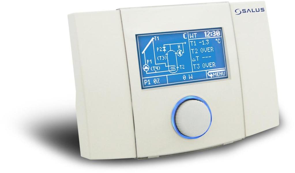


1 Controller PCSol 300 FOR SOLAR COLLECTORS PUMP PUMP CIRCULATION PUMP ROTATION CONTROL CIRCULATION PROGRAM HEATER SUPPORT HEATER PROGRAM SIMPLE IN USE INTELLIGENT ALARM CLOCK 10 DAYS CLOCK SUSTAIN TEMPORARY POWER HEAD OUTPUT ANTI-FREEZING NIGHT COOLING GRAPHIC DISPLAY HEAT DISCHARGE POOL TANK PROTECTION TWO COMPASS DIRECTIONS VACUUM COLLECTOR INSTALLATION AND OPERATION MANUAL 62.X.2 REVISION SOFTWARE
2
3 CONTENTS 1. SAFE INSTALLATION AND USE 4 2. GENERAL 5 3. DIRECTIVE WEEE 2002/96/EC 5 4. DOCUMENT KEEPING 5 OPERATING MANUAL 7 5. OPERATION 8 6. CONTROLLER MENU 8 7. SETTINGS MENU SETTINGS MENU TIME PROGRAMS TDHWMIN CIRCULATION MENU ALARMS OPTIONS MENU RESTORING FACTORY SETTINGS READING DEFAULT SETTINGS CLEARING HEAT OUTPUT DATA OPERATION MANU OPERATION\SETTINGS MENU OPERATION\LOUDNESS MENU OPERATION\CLOCK MENU HEAT OUTPUT SOLAR APPLICATIONS NIGHT COOLING SOLAR THERMAL SCHEME A SOLAR THERMAL SCHEME B SOLAR THERMAL SCHEME C SOLAR THERMAL SCHEME D SOLAR THERMAL SCHEME E SOLAR THERMAL SCHEME F SOLAR THERMAL SCHEME G SOLAR THERMAL SCHEME H SOLAR THERMAL SCHEME I SOLAR THERMAL SCHEME J SOLAR THERMAL SCHEME K SOLAR THERMAL SCHEME L SHUT DOWN ACCESS TO THE UNIT OVER THE INTERNET BASIC DATA READING DIAGRAM OF ACTIVE SOLAR CIRCUIT SYSTEM USER PARAMETERS SERVICE PARAMETERS HEAT YIELD GRAPH NETWORK SETTINGS INSTALLATION MANUAL TECHNICAL DATA ELEMENTS OF THE SET INSTALLATION OF PCSOL INSTALLATION OF THE CONTROLLER EXTERNAL CIRCUITS CONNECTION Use of connectors Power supply connection Temperature sensor connection Temperature sensor installation Output H connection econet internet module connection APPLICATION SCHEMES SOLAR APPLICATION SCHEME A SOLAR APPLICATION SCHEME B SOLAR APPLICATION SCHEME C SOLAR APPLICATION SCHEME D SOLAR APPLICATION SCHEME E SOLAR APPLICATION SCHEME F SOLAR APPLICATION SCHEME G SOLAR APPLICATION SCHEME H SOLAR APPLICATION SCHEME I SOLAR APPLICATION SCHEME J SOLAR APPLICATION SCHEME K APLIKACJA SCHEMAT SOLARNY L CASING CLOSING CONTROLLER OPTIONS SYSTEM OPTIONS\SETTINGS I\O OPTIONS\CONFIGURATION Wire length compensation OPTIONS\FUNCTIONS Vacuum collector function MANUAL MODE SCHEME WIZARD FUSE REPLACEMENT 53 3
4 1. SAFE INSTALLATION AND USE The controller is designed only for household and similar use. Before installation, service or maintenance and prior to making any connections, always disconnect power supply and make sure that the terminals and electric wires are not energized. When the controller is switched off using keyboard or encoder, the controller terminals are still under dangerous voltage. Controller may be used only for its intended purpose. It is required to use auxiliary protection automatics to protect hot water system, CH system (if any) in case of the controller or software malfunction Programmable settings must be selected suitably to your system type, taking into account all of its operating conditions. Wrongful settings may cause the collector or reservoir malfunction (e.g. collector overheating, etc.). Before you open casing, first disconnect power supply from the unit. The controller must be installed in accordance with the requirements of EN standard, by qualified and authorized technician. Do not install the unit when it is connected to voltage. Short circuit in pump output will damage your unit. Do not operate the unit when it is malfunctioning or was repaired by unauthorized persons. Do not mount the unit on flammable materials. Programmed settings may be modified only by a person who read and understood this manual. Use only in heating systems that are set up in accordance with valid regulations. Electric system to which the controller is connected must be protected with a cutout device suitable for expected loads. Never use the controller when its casing is damaged. In any case do not alter the controller components. The controller has electronic disconnection for connected devices (operation 2.B according to PN-EN ). It means that at 230V voltage supply the pump outlets have dangerous voltage, even if the pumps are not controlled. Do not allow children access to the controller. 4


5 2. GENERAL Controller PCSol 300 is an advanced electronic unit designed for distribution of heat from solar collectors. The controller is used to control solar circuit systems accordingly to indications from temperature sensors to recover highest possible energy from the collector. 4. DOCUMENT KEEPING Please, keep carefully this installation and operating manual and any other relevant documents, so that they may be used at any time. In case when you move or sell the unit, please give the attached documents to its new user. PCSol300 Fig. 2.1 Basic functional diagram 3. DIRECTIVE WEEE 2002/96/EC The product you have purchased was designed and made using the highest quality components that may be recycled and reused. If the product is marked with the above crossed bin symbol, it means that it meets requirements of the European Directive 2002/96/EC. It is recommended to know your local electric and electronic products disposal system. It is recommended to process in accordance with local regulations and not to dispose used products to household garbage containers. Proper disposal of outdated products will help to avoid potential adverse effects on the environment and human health. 5
6
7 OPERATING MANUAL PCSol 300


8 5. OPERATION The controller has TOUCH&PLAY system that facilitates its operation. Encoder is operated by its rotating and pressing. To start the controller, keep pressed encoder knob for 3 seconds. Welcome screen will be displayed: 6. CONTROLLER MENU 3sek. Any time during controller operation, when you keep the encoder pressed for 3 seconds. it will cause exit to the main screen. All controller settings are made through menu system. MENU is recalled by pressing encoder on main screen to select icon. Fig. 6.1 Recalling controller s menu When MENU is open, the unit will display a screen with icons that represent the controller functions: Fig. 5.1 Welcome screen * * starting screen may differ depending on controller version. After the welcome screen the controller displays the main screen. Fig. 6.2 Controller menu In middle on the screen you can see active item icon selected as in Fig Now, you may turn encoder knob to move through menu items. In main MENU there will be: Fig. 5.2 Main screen Controller outlets operation is each time indicated by their blinking on displayed diagram. Fig. 6.3 Main menu items Where: Icon TDHWmin (second one) is shown only, if active scheme is B and J. Circulation icon (third one), if active scheme is B, C, D, E, G, H, J,K, L. 8

9 Values of settings are edited in scrollable submenu. Example for submenu preset is shown below. To edit setting value select required setting and press the knob; the value will start blinking. Now, rotate the knob to change the setting value. The changed value will be confirmed, when you press the knob again, and you may select other setting. After edition in submenu you may select the following by pressing on selection: OK Confirms changes and exits to menu; it allows reverse reaction to encoder turning; CANCEL Rejects changes in entire submenu and exits to menu. Fig. 6.4 Scrollable submenu only A, B, C, E, F, H, I, J, L only B only B, C, D, E, G, H, J, K, L Fig. 6.5 Controller s menu structure 9

, during edition it may be seen that the temperature has the same value all along the diagram. Fig. 8.")

10 7. SETTINGS MENU Access This menu is used to make basic settings of the controller. Change of parameters is only accepted when you use OK in left lower corner of the screen. Use CANCEL to reject any made changes. List of parameters in this menu depends on selected solar scheme. Parameters are described in details in section 13 about particular solar applications. Depending on scheme and version of unit, the following parameters are available in Settings menu: When you switch off the temperature value in value edition box, the time program will be set off and the controller will use stable value for TDHWmin parameter (single temperature value all the time), during edition it may be seen that the temperature has the same value all along the diagram. Fig. 8.1 Edition of TDHWmin value To set the TDHWmin to change in time, it is required to set schedule. It is done by setting sch. value in value edition box.. Scheme Parameter A B C D E F G H I J K L TsDHW X X X X X X X X X X X dtab X X dtco X Eco mode X Night cooling X X X X X X X X X Night cooling ON X X X X X X X X X Night cooling OFF X X X X X X X X X TsPOOL X X Priority X Alarm TCOLcr X X X X X X X X X X X X Fig. 8.2 Activating time program for TDHWmin When sch. value is confirmed, new item MO-FR will be displayed; edit this value to select one of the three time ranges: MO-FR time program for days Monday to Friday, SAT. time program for Saturday, SUN. time program for Sunday. After you confirmed desired time range, use the knob to move the position marker to the place (hour range), for which you want to edit value. 8. TIME PROGRAMS For correct operation of time programs it is required to set the clock TDHWmin Access Item available only in B scheme Fig. 8.3 Setting marker position Here, press the knob to hide the position marker and to light the edition marker. When the edition marker is lit, turn the knob to change temperature value for current position marker. Time program TDHWmin is minimal temperature of DHT reservoir (T3 sensor), below which the controller controls H output (heater or other additional heat source). 10


11 Edition marker Current marker hour range Current marker value Fig. 8.4 Setting edition marker When you set temperature and pressed the knob, both edition marker and position marker will be displayed on the screen, and you may turn the knob to copy the value to adjacent positions. Press again the knob to move to the position marker. Fig. 8.6 Menu structure Possible settings in value edit box are YES, NO AND sch. Value YES will enable constant circulation. Value NO will disable circulation. Value sch. will activate time program for circulation. 9. MENU ALARMS Access Fig. 8.5 Setting value movement Select OK and press the knob, while in position marker mode, to confirm changes made in schedules. Activate CANCEL to exit without saving changes in schedules Circulation Access Item available only in schemes B, C, D, E, G, H, J, K, L Changes in circulation time programs are introduced the same like it was demonstrated for TDHWmin schedule settings. The controller may alarm on any irregularities in operation. The controller has an intelligent alarm function. It means that the controller recognizes type of alarm condition and takes respective remedy actions accordingly to the conditions. For instance, if the sensor of reservoir extra heating with a heater fails, the controller prevents extra heating for the reservoir. Despite of alarm, the solar circuit will continue correct operation and the controller will not let the reservoir to be overheated. Type of action taken by the smart alarm depends on the alarm type and on the solar application. When in the main screen in the screen bottom ALARM! sign starts blinking (Fig. 5.2), it means alarm situation. Now, entering through menu to Alarms we have access to contents and code number of alarm reported by the controller (Fig. below). 11

12 Fig. 9.1 Alarm screen If the shown item number is higher than 1, it means multiple alarms, to be seen by turning the knob. Lower left corner indicates the alarm code. Alarm codes are summarized in the table below, to facilitate their identifications and remedies: List of alarms No. Alarm 1 DHW reservoir overheating Maximal DHW reservoir temperature has been reached (exceeded temperature specified as TDHWmax). Pump that loads heat to reservoir is stopped. This alarm has higher priority than collector alarms (if collector temperature alarms occur at the same time, solar pump will not be started whatsoever). It is required to cool reservoir, e.g. by discharging hot water. Solar panel overheating 2 P1 stop Collector pump will be stopped by the time, when collector temperature drops below TCOLmax. It is possible to start pump in manual service mode. Check work fluid flow (possible air in system or collector pump is not controlled). This alarm may be due to exceeded reservoir temperature alarm (Code 1). 3 Solar panel critical temperature It means that collector critical temperature has been reached (parameter TCOLcr) and despite reaching temperatures (TsDHW, TsPOOL) collector pump will be started, until collector temperature drops below TCOLcr. Wait for collector cool down. If menu option Alarm TCOLcr is set as NO, controller will not report this alarm, but it will take described actions. 4 T1 sensor malfunction Alarm informs on incorrect operation or damage to T1 sensor. Check connections for continuity (connect) or short circuit (eliminate) in sensor circuit. Alarm will stop collector pump, algorithm stops DHW reservoir loading. 5 T2 sensor malfunction Alarm informs on incorrect operation or damage to T2 sensor. Check connections for continuity (connect) or short circuit (eliminate) in sensor circuit. Alarm will stop collector pump, algorithm stops DHW reservoir loading. 6 T3 sensor malfunction Alarm informs on incorrect operation or damage to T3 sensor. Check connections for continuity (connect) or short circuit (eliminate) in sensor circuit. This alarm depends on solar thermal scheme. At B scheme (with heater) extra heating of reservoir will be stopped (output H is off) and alarm is not reported. In schemes A, C sensor has informative function and controller will not report any alarms from these sensors. 7 T4 sensor malfunction Alarm informs on incorrect operation or damage to T4 sensor. Check connections for continuity (connect) or short circuit (eliminate) in sensor circuit. This alarm depends on Solar thermal scheme. Alarm is reported only at schemes D, G or K, where operational algorithm requires this sensor. At other schemes (B, C, E, F, H, I*) T4 sensor is used to calculate heat output and its malfunction is not reported, while heat output is not calculated. *T4 sensor operation in I scheme depends on dtp2 parameter, as described in section DHW A reservoir overheating An alarm informing that the TDHWmax defined maximum temperature of DHW A (A buffer in K scheme) has been reached. A pump loading heat into this container/buffer will be halted. Container/buffer should be cooled down, e.g. by letting warm water our and/or disconnecting alternative heat source from the container. 9 DHW B reservoir overheating Alarm on reaching maximal temperature defined in TDHWmax parameter in DHW B reservoir. Pump that loads heat to this reservoir will be stopped. Cool down this reservoir, e.g. by hot water discharge. 10 Solar panel A critical temperature In system with two collectors (only Solar thermal scheme H) alarm on exceeding critical temperature (parameter TCOLcr) in A collector. Controller, despite that preset temperature TsDHW is reached, will start collector pump P1 in order to lower temperature below critical. Wait for collector cool down. If menu option Alarm TCOLcr is set as NO, controller will not report this alarm, but it will take described actions. 12

 will be stopped, until collector temperature drops below TCOLmax. It is possible to start pump in manual service mode. 13 Solar panel B overheating.")

13 11 Solar panel B critical temperature In system with two collectors (only Solar thermal scheme H) alarm on exceeding critical temperature (parameter TCOLcr) in B collector. Controller, despite that preset temperature TsDHW is reached, will start collector pump P2 in order to lower temperature below critical. Wait for collector cool down. If menu option Alarm TCOLcr is set as NO, controller will not report this alarm, but it will take described actions. 12 Solar panel A overheating. P1 stop A circuit collector pump (at scheme H) will be stopped, until collector temperature drops below TCOLmax. It is possible to start pump in manual service mode. 13 Solar panel B overheating. P2 stop B circuit collector pump (at scheme H) will be stopped, until collector temperature drops below TCOLmax. It is possible to start pump in manual service mode. 14 Antifreeze STOP During antifreeze performance collector pump is started to increase temperature of too cold solar work fluid. Energy from reservoir or pool will be used for this purpose. However, if reservoir or pool temperature is near 2 C, controller will stop antifreeze function to prevent heat source damage and will initiate alarm. Antifreeze function is wider described in section Options\Functions OPTIONS MENU Access You must log-in to enter the options. Login screen is presented in Fig Restoring factory settings This menu allows restoring factory parameters and settings. In login screen enter password 0002 and confirm to restore only default user settings. Service parameters will not be changed. After restoration of factory settings, parameters available in Options menu will not be changed. Before restoration the controller will show a request to confirm this action. After restoring factory settings you must set the clock, as it has been reset to date: 00:00, Reading default settings The controller has default settings table (that will be restored). Default settings may be read by entering password 0005 in login screen. The table is only for reading type and it may not be edited Clearing heat output data Password 0003 will clear any heat output chart in the controller. Password 0004 will clear heat output counter. After entering passwords 0003 and 0004 the controller will display request for confirmation. Select NO to exit without changes. List of codes 0000 Table of option submenu settings only for reading 0002 Restores default settings of User group (not protected with password) 0003 Clears heat output chart 0004 Clears heat output counter 0005 Default settings table Access to Options submenu Restores default settings in groups User and Service in controller (all parameters) 11. OPERATION MANU This menu is dedicated to the user. Here, you may change basic settings of the controller only operation. Fig User login screen Access to this menu is protected with password. This menu settings are used by installer/servicer. Detailed description of the options parameters is included in installation part of the manual. Password 0000 will display submenu parameters only for reading Operation\Settings Menu Access This menu allows the user to access: 13

 includes information on microcontroller and software compilation; Language allows changing language of descriptions.")

14 Nameplate It has three pages. Navigate between pages by turning the knob left/right. First page (1/3) allows you to read information on the unit hardware and software version; Operation\Loudness Menu This many includes sound settings. Turn encoder to move between sound settings and controller s message sounds on and off. PCSol 300 Fig Page (1/3) of Nameplate Page (2/3) includes manufacturer s contact details. About OK Fig Strona (2/3) Tabliczki znamionowej. Page (3/3) includes information on microcontroller and software compilation; Language allows changing language of descriptions. You may select the following: PL-Polish, EN-English, IT-Italian, ES-Spanish, DA-Danish, RO-Romanian, EL-Greek, FR-French, CS-Czech, RU-Russian, DE-German; Encoder direction reverts reaction for encoder turning; Time Out inactivity time, in seconds, after which the unit automatically exits menu and the screen and knob illumination go off; Menu speed adjusts fastness of menu animations; Ambient light sets illumination pulsating after the display turned off (when Time Out has elapsed). This function is useful to find the controller in dark rooms. Encoder knob light pulsation will be also performed after the controller is switched off. Fig Sound settings screen. When sounds are switched off, the knob turning will not be confirmed by acoustic signals. Switching alarm sounds on will cause that alarm events are reported together with sound signal. If this option is unchecked, any alarm messages will be silent: only display blinking. Alarms will not be confirmed by sound signal Operation\Clock Menu Access For correct operation of time programs the unit uses real-time clock, which must be set before the controller start working. Not set or wrongly set clock will cause incorrect operation of time programs and night cooling function Day of week as seen in main window will be calculated automatically. Fig Clock setting screen 14

. In the main screen, the controller displays data for 7 days.")

15 Date and time setting must be confirmed with OK. When you select CANCEL, any changes will be rejected. The controller has function of sustaining clock for 10 days. After this time, if power supply is not restored, the clock will reset. 12. HEAT OUTPUT Access First bar in the chart stands for energy recovered on current day and it is updated every full hour. At midnight, the controller will move data one position to the right and start counting for new current day. It is possible to turn the heat output chart on in the main screen (in place where active Solar thermal scheme is displayed). In the main screen, the controller displays data for 7 days. The controller counts energy recovered from the collector. Heat output visualization differs depending on the controller version. Heat output function is not available in solar thermal schemes D, G and K. Calculation of heat output and momentary power requires additional temperature sensor CT6 connected to measurement input T4. If the sensor is not connected, heat output will not be counted. In solar applications that for their operation require four temperature sensors, heat output counting is not possible. These applications are D and G. When the schemes are on, the controller menu will not display heat output icon and the function may not be entered. The controller logs data on recovered energy from last 14 days in the form of bar chart. Fig Heat output in main screen Data are updated every full hour and the entire chart is moved at midnight. To see data for previous days, you must enter the heat output menu. Fig Heat output in main screen Fig Heat output screen Energy total counter is displayed at the bottom of the screen. It counts energy recovered from the solar panel from the beginning of the unit s lifetime. The counter data are stored in non-volatile memory that is not affected by power losses. 15

16 13. SOLAR APPLICATIONS Night cooling Due to the fact that in solar thermal schemes C, F, I there is no risk of reservoir overheating and that other protection means are provided for them against overheating, the function of night cooling is not available in these schemes. For correct operation of night cooling it is required that the clock is set. Night cooling function is used to cool DHW reservoir by emitting excess heat through cold collector. It is done by starting the collector pump. During night cooling, any alternative sources of energy will be switched off. There are three settings for night cooling function: Night cooling, Night cooling ON, Night cooling OFF and they are in Adjustment menu. Night cooling- YES: switches on, NO: switches off the night cooling mode. When the mode is on, the controller, in hours , if T2 sensor temperature is higher than specified in Night cooling ON setting; will decide to start night cooling. The controller will start the collector pump in order to discharge to reservoir and will be cooling the reservoir to reach temperature specified in Night cooling OFF setting. In this mode, the controller additionally monitors the collector temperature; cooling will be stopped for some time, if T1+dToff>T2. Regardless prior conditions, the controller will exit from the cooling mode at 5 00 and return to normal operation. Activation of night cooling mode is indicated in the screen as blinking moon icon near the collector picture. Night cooling ON - DHW reservoir temperature (measured by T2), when reached, if night cooling function is enabled (prior item) and the temperature at T2 sensor is higher than Night cooling ON temperature, the controller will decide on night cooling activation. The controller will start the collector pump to discharge the reservoir and it will continue to cool the reservoir to the temperature set for Night cooling OFF. Night cooling OFF - DHW reservoir temperature (T2 sensor), to which the controller will be cooling the reservoir during night cooling function. When the temperature drops to the one specified for Night cooling OFF, the controller will stop night cooling. Additionally, depending on selected scheme, the controller will control additional outputs, so as to discharge heat more efficiently. 16 In scheme B during night cooling, circulation on output P2 will be activated (regardless any time programs etc.); heater operation will stopped (output H is turned off, regardless any time programs etc.). In schemes D, E, G, J, K during night cooling, circulation on output H will be activated (regardless any time programs etc.) Solar thermal scheme A Loading of DHW reservoir with solar collector. This basic solar application. Fig Solar thermal scheme A The collector pump will be started with 100% capacity, when difference between T1 and T2 exceeds value of dtondhw setting and it will be working for the time specified in tp setting. If upon this time the difference between T1 and T2 is still above dtondhw, the pump speed will remain at 100%. If the temperature difference between T1 and T2 drops below dtondhw, the controller will start reducing the pump speed, until the moment when T1 and T2 difference reaches value specified in dtoffdhw setting. When T1 and T2 difference is between the values dtondhw dtoffdhw, the controller will calculate and set the pump speed proportionally. When dtoffdhw is reached, the pump will work at minimal speed (parameter Pmin), below it will be stopped. System will work by the time when T2 sensor preset temperature TsDHW is reached, than the collector pump P1 is stopped. If the collector temperature T1 reaches critical value (TCOLcr parameter), the controller will allow the collector pump to be switched on to lower the collector temperature below HP1 hysteresis parameter. If the reservoir temperature on T2 sensor reaches the value of TDHWmax, than the controller, despite critical collector s temperature (TCOLcr), will stop the collector pump, disabling the collector cooling. It is to protect the reservoir from overheating.
, if exceeded at 0 00, if night cooling function is enabled, the controller will decide on night cooling activation.")
17 List of settings in Adjustment menu TsDHW- Reservoir temperature preset. Night cooling- YES enables / NO disables night cooling in hours Night cooling ON DHW reservoir temperature (T2 sensor), if exceeded at 0 00, if night cooling function is enabled, the controller will decide on night cooling activation. Night cooling OFF DHW reservoir temperature (T2 sensor), to which the controller will cool the reservoir (if night cooling is enabled and in hours Night cooling ON temperature is exceeded). Alarm TCOLcr Switching on (YES) or off (NO) the alarm on exceeding TCOLcr temperature. This function does not affect the controller s operation. If the setting is set as NO, the controller will not report any alarm after TCOLcr temperature has been exceeded on the collector s sensor. Due to heat discharge function, this scheme has no night cooling function Solar thermal scheme B Loading of DHW reservoir with a function of extra heating by the use of a heater. Fig Solar thermal scheme B The collector pump will be started with 100% capacity, if the difference between T1 and T2 exceeds value of dtondhw setting and it will work for the time as specified in tp. If after this time the difference between T1 and T2 is still above dtondhw, the pump speed will remain at 100%. If the said difference T1 and T2 drops below dtondhw, the controller will start reducing the pump speed, until the difference between T1 and T2 reaches the value specified as dtoffdhw. When the difference between T1 and T2 is between the values dtondhw dtoffdhw, the controller will calculate and set pump speed proportionally. If dtoffdhw is reached, the pump will work at minimal speed (parameter Pmin), below it will be stopped. The controller will heat up CWU reservoir using a heater or other heat source (H output) up to the temperature of TDHWmin. Functioning of H output depends also on eco function set up, as described in Adjustment menu. TDHWmin temperature is set through main menu item TDHWmin. List of settings in Adjustment menu: TsDHW- Reservoir temperature preset. Eco mode- economic mode on or off (power saving) YES Extra heating of DHW reservoir with a heater or other source of heat (H output) to the temperature of TDHWmin, when the collector is not working (P1 pump stops due to poor sunlight). When the collector pumpis started, the controller will turn the heater off (H output). NO Extra heating of DHW reservoir with a heater or other source of heat (H output) up to the temperature of TDHWmin, regardless if the collector supplies energy or not. Night cooling- YES enables / NO disables night cooling mode in hours Night cooling ON DHW reservoir temperature (T2 sensor), which if exceeded at 0 00 (if night cooling function is enabled), the controller will decide on night cooling activation. Night cooling OFF DHW reservoir temperature (T2 sensor), to which the controller will be cooling down the reservoir (if night cooling function is enabled and in hours the temperature of Night cooling ON has been exceeded). Alarm TCOLcr Switches on (YES) or off (NO) the alarm on exceeding TCOLcr temperature. This function will not affect the controller operation. If the parameter is set as NO, the controller will not alarm when the temperature of TCOLcr is exceeded at the collector s sensor Solar thermal scheme C Loading of DHW reservoir with excess heat discharge function. Fig Solar thermal scheme C The collector pump will be started with 100% capacity, if the difference between T1 and T2 exceeds value of dtondhw setting and it will be working for the time specified in tp parameter. If after this time the difference between T1 and T2 is still above 17

18 dtondhw, the pump speed will remain at 100%. If the said difference between temperatures T1 and T2 drops below dtondhw, the controller will start reducing the pump speed, until the difference between T1 and T2 reaches the value specified as dtoffdhw. If the difference between T1 and T2 is between the values dtondhw dtoffdhw, the controller will calculate and set the pump speed proportionally. When dtoffdhw is reached, the pump will work at minimal speed (Pmin parameter), below it will be stopped. The system will operate by the time when T2 sensor temperature reaches the preset TsDHW, and then it will be stopped. If T1 collector temperature reaches critical value (TCOLcr), than the collector will allow the collector pump to be switched on, to reduce the critical temperature blow hysteresis HP1. If the reservoir reaches maximal temperature TDHWmax, the P2 input (controls discharge valve) will be operated, until the reservoir temperature (T2 sensor) drops to the value T2<TDHWmax-HP2. List of settings in Adjustment menu: TsDHW- Reservoir temperature preset. Alarm TCOLcr Switching on (YES) or off (NO) the alarm on exceeding TCOLcr temperature. This function will not affect the controller operation. If the parameter is set as NO the controller will not alarm after TCOLcr temperature has been exceeded at the collector s sensor Solar thermal scheme D Loading of DHW reservoir A with a function for heat transfer to DHW reservoir B. Fig Solar thermal scheme D The collector pump will be started with 100% capacity, if the difference between T1 and T2 exceeds the value of dtondhw setting, and it will be working for the time specified in parameter tp. If after this time the difference between T1 and T2 is still above dtondhw, the pump speed will remain at 100%. If the said difference between T1 and T2 drops below dtondhw, the controller will start reducing the pump speed, until the difference between T1 and T2 reaches the value specified as dtoffdhw. If the difference between T1 and T2 is between the values dtondhw dtoffdhw, the controller will calculate and set the pump speed proportionally. When dtoffdhw is reached, the pump will work at minimal speed (Pmin parameter), below it will be stopped. If the difference between A and B reservoir temperature reaches the value of dtab (T3 and T4 difference), P2 will be started to transfer heat to the reservoir B. The pump will be stopped, if the difference between temperatures T3 and T4 drops below the difference dtab-hp2). If the collector temperature T1 reaches the value of TCOLcr, the collector pump will be started (despite of reaching TsDHW temperature). This is aimed to reduce the collector s temperature. It will be stopped, when T1 temperature drops below T1<TCOLcr-HP1, or if the reservoir temperature at T2 sensor reaches the value of TDHWmax. List of settings in Adjustment menu TsDHW- Reservoir temperature preset A and B. dtab- temperature difference between reservoirs A and B (T3 and T4 sensors), that when reached causes the controller to start P2 pump, which transfers heat to the reservoir B. P2 will be stopped, if the difference of dtab (T3 and T4 temperatures) drops by the value of auxiliary hysteresis HP2. Night cooling- YES enables / NO disables night cooling mode in hours Night cooling ON DHW reservoir temperature (T2 sensor) that when exceeded at 0 00, if night cooling function is enabled, the controller will decide on night cooling activation. Night cooling OFF DHW reservoir temperature (T2 sensor), to which the controller will be cooling down the reservoir (if night cooling function is enabled and if between Night cooling ON temperature was exceeded). Alarm TCOLcr Switching on (YES) or off (NO) the alarm on exceeding TCOLcr temperature. This function will not affect the controller operation. If the parameter is set as NO, the controller will not alarm if TCOLcr temperature has been exceeded at the collector s sensor. 18

.")
19 13.6. Solar thermal scheme E Loading of two DHW reservoirs A and B with priority function for reservoir A. Fig Solar thermal scheme E Both reservoirs are loaded up to the temperature set as TsDHW, measured at T2 sensor for reservoir A or T3 sensor for reservoir B. The controller checks which reservoir has not reached the temperature preset and decides on loading to this reservoir. If neither of the reservoirs has reached the temperature preset, the controller first loads the reservoir A (reservoir A priority). The collector pump P1 for the reservoir A or P2 for the reservoir B will be started at 100% capacity for the reservoir (depending on which one has not reached temperature preset), if the difference between T1 and T2 (for reservoir A) or T1 and T3 (for reservoir B) exceeds the value of dtondhw setting. The pump will be working for the time specified in tp setting. If after this time the difference between T1 and T2 or T3 is still above dtondhw, the pump speed will remain at 100%. If the said difference between temperatures drops below dtondhw, the controller will start reducing the pump speed, until the value of dtoffdhw is reached. If the difference between T1 and T2 or T3 is between the values dtondhw dtoffdhw, the controller will calculate and set the pump speed proportionally. When dtoffdhw is reached, the pump will work at minimal speed (Pmin), below it will be stopped. System will switch again to reservoir A loading, when the temperature drops below the value of HP1 hysteresis. Operating algorithm of the collector pump P1 with the reservoir A is identical as for the pump P2 at loading the reservoir B. When both reservoirs reach the temperature preset TsDHW, the collector pumps will be stopped. The will be started at the moment, when in one of the reservoirs the temperature drops in relation to the temperature preset of hysteresis: respectively HP1 for P1 pump and HP2 for P2 pump. Eventually, when the temperature at the collector sensor T1 will reach critical value (TCOLcr). Then, the controller will allow switching on the collector pump for the reservoir A or B (with the priority for the reservoir A), by the time, when the reservoirs temperatures reach TDHWmax. This will cause the collector pumps to stop. List of settings in Adjustment menu: TsDHW- Reservoir temperature preset A or B. Night cooling- YES switches on / NO switches off night cooling mode in hours Night cooling ON DHW reservoir temperature (T2 sensor), when exceed at 0 00, if night cooling function is enabled, the controller will decide on night cooling activation. Night cooling OFF DHW reservoir temperature (T2 sensor) to which the controller will be cooling down the reservoir (if night cooling function is enabled and if in hours Night cooling ON temperature has been exceeded). Alarm TCOLcr Switching on (YES) or off (NO) the alarm on exceeding TCOLcr temperature. This function will not affect the controller operation. If the parameter is set as NO, the controller will not alarm after exceeding TCOLcr temperature at the collector sensor Solar thermal scheme F Loading of DHW reservoir and pool with priorities function. Fig Solar thermal scheme F Depending on Priority setting (Pool/DHW), the system will first load the circuit to temperature preset of TsDHW or TsPOOL. If the reservoir circuit has priority and it has not reached its temperature preset, then the collector pump will be started with 100% capacity, if the difference between T1 and T2 exceeds value of dtondhw, and it will be working for the time specified in parameter tp. If after this time the difference between T1 and T2 is still above dtondhw, the pump speed will remain at 100%. If the said difference between T1 and T2 drops below dtondhw, the controller will start reducing the pump speed, until the difference between T1 and T2 reaches the value specified as dtoffdhw. If the difference 19
, below it will be stopped. After reaching preset temperature in priority circuit, the controller will switch the circuit.")
20 between T1 and T2 is between the values dtondhw dtoffdhw the controller will calculate and set pump speed proportionally. When dtoffdhw is reached, the pump will work at minimal speed (Pmin), below it will be stopped. After reaching preset temperature in priority circuit, the controller will switch the circuit. The pool circuit will work analogically, except that the temperatures are calculated from T1 and T3 and the system uses auxiliary deltas dtonpool dtoffpool. Pool exchanger P2 pump is always switched on/off with delay as specified in tdly setting in relation to P1 pump. When the second circuit is heated up to preset temperature, the collector pump is stopped. It will be restarted, when on any circuit the temperature drops by hysteresis value (HP1), in accordance with priority setting. If the collector temperature reaches TCOLcr value, the collector pump will be started and the circuit will be switched to priority one in order to reduce the collector temperature. It will be stopped, when T1 temperature drops below T1<TCOLcr-HP1. If Priority is set for DHW, the collector unloading will be continued only to the time when TDHWmax is reached, and then the system switches to the pool. In the pool circuit there is no upper limit for discharging collector s critical temperature. Switching between DHW/POOL is controlled through H output. The circuit operation starts only when the switching time elapsed (tvalve). 20 Due to pool system, the scheme has no night cooling function. List of settings in Adjustment menu TsDHW- Reservoir temperature preset TsPOOL- Pool temperature preset Priority- Priority setting: reservoir (DHW) or pool (POOL) loading. Alarm TCOLcr Switching on (YES) or off (NO) the alarm on exceeding TCOLcr temperature. This function will not affect the controller operation. If the parameter is set as NO the controller will not alarm when TCOLcr temperature is exceeded at the collector sensor Solar thermal scheme G Loading of DHW reservoir with solar collector and boiler. Fig Solar thermal scheme G The collector pump will be started with 100% capacity, if the difference between T1 and T2 exceeds value of dtondhw setting and it will be working for the time specified in parameter tp. If after this time the difference between T1 and T2 is still above dtondhw, the pump speed will remain at 100%. If the said difference between T1 and T2 drops below dtondhw, the controller will start reducing the pump speed, until the difference between T1 and T2 reaches the value specified as dtoffdhw. If the difference between T1 and T2 is between the values dtondhw dtoffdhw, the controller will calculate and set the pump speed proportionally. When dtoffdhw is reached, the pump will work at minimal speed (Pmin), below it will be stopped. If TsDHW temperature is reached for sensor: T2- reservoir loading from collector will be stopped; T3 reservoir loading from boiler will be stropped. The reservoir loading will be restarted, when one of the temperatures T2 or T3 drops below hysteresis HP1 for T2 or HP2 for T3. If the collector temperature T1 reaches the value of TCOLcr, then the collector pump will be started (despite of reaching TsDHW temperature). It is aimed to reduce the collector s temperature. It will be stopped, when T1 drops below T1<TCOLcr-HP1, or if the reservoir temperature at T2 sensor reaches the value of TDHWmax. List of settings in Adjustment menu TsDHW- Reservoir temperature preset dtco Minimal temperature difference between T4 and T3 that starts loading of DHW reservoir from boiler circuit CH (starting P2 pump). Night cooling- Yes enables/ NO disables night cooling mode in hours Night cooling ON DHW reservoir temperature (T2 sensor), when exceeded at 0 00 if night
, to which the controller will be cooling down the reservoir (if night cooling function is enabled and if in hours 0 00 5 00 Night cooling ON")
21 cooling function is enabled, the controller will decide on night cooling activation. Night cooling OFF DHW reservoir temperature (T2 sensor), to which the controller will be cooling down the reservoir (if night cooling function is enabled and if in hours Night cooling ON temperature is exceeded). Alarm TCOLcr Switching on (YES) or off (NO) the alarm on exceeding TCOLcr temperature. This function will not affect the controller operation. If the parameter is set as NO, the controller will not alarm when TCOLcr temperature is exceeded at the collector sensor Solar thermal scheme H Loading of DHW reservoir with two collector sets oriented toward two directions. Fig Solar thermal scheme H The collector pump P1 of collector A will be started at 100% capacity, if the difference between T1 and T2 exceeds the value of dtondhw and it will be working for the time specified in parameter tp. If after this time the difference between T1 and T2 is still above dtondhw, the pump speed will remain at 100%. If the said difference between T1 and T2 drops below dtondhw, the controller will start reducing the pump speed, until the difference between T1 and T2 reaches the value specified as dtoffdhw. If the difference between T1 and T2 is between the values dtondhw dtoffdhw, the controller will calculate and set the pump speed proportionally. When dtoffdhw is reached, the pump will work at minimal speed (Pmin), below it will be stopped. The collector pump P2 of collector B will be started at 100% capacity, if the difference between T3 and T2 exceeds the value of dtondhw and it will be working for the time specified in parameter tp. If after this time the difference T3 and T2 is still above dtondhw, the pump speed will remain at 100%. If the said difference between T3 and T2 drops below dtondhw, the controller will start reducing the pump speed, until the difference between T3 and T2 reaches the value specified as dtoffdhw. If the difference between T3 and T2 is between the values dtondhw dtoffdhw, the controller will calculate and set the pump speed proportionally. When dtoffdhw is reached, the pump will work at minimal speed (Pmin), below it will be stopped. The system will work, until T2 sensor reaches TsDHW preset, then collector pumps P1 and P2 are stopped. If T1 or T3 collector temperature reaches critical value (TCOLcr), then the controller will allow switching on pump P1 or P2 (depending which collector has critical temperature) in order to reduce the collector temperature below hysteresis HP1 for P1 and HP2 for P2. If the reservoir temperature at T2 sensor reaches the value of TDHWmax, the controller, despite of critical collector temperature (TCOLcr), will stop the collector pumps, disabling the collector cooling. It is to protect the reservoir from overheating. List of parameters in Adjustment menu TsDHW- Reservoir temperature preset Night cooling- YES enables/ NO disables night cooling mode in hours Night cooling ON DHW reservoir temperature (T2 sensor), when exceeded at 0 00 if night cooling function is enabled, the controller will decide on night cooling activation. Night cooling OFF DHW reservoir temperature (T2 sensor), to which the controller will be cooling down the reservoir (if night cooling function is enabled and if in hours Night cooling ON temperature is exceeded). Alarm TCOLcr Switching on (YES) or off (NO) the alarm on exceeding TCOLcr temperature. This function will not affect the controller operation. If the parameter is set as NO the controller will not alarm after TCOLcr is exceeded for the collector sensors T1 and T Solar thermal scheme I Loading of pool system. Fig Solar thermal scheme I The collector pump will be started with 100% capacity, if the difference between T1 and T2 exceeds the value of dtonpool and it will be working for the time specified in parameter tp. If after this time the difference between T1 and T2 is still above dtonpool, the pump speed will remain at 100%. If the said difference between 21

22 T1 and T2 drops below dtonpool, the controller will start reducing the pump speed, until the difference between T1 and T2 reaches the value specified as dtoffpool. If the difference between T1 and T2 is between the values dtonpool dtoffpool, the controller will calculate and set pump speed proportionally. When dtoffpool is reached, the pump will work at minimal speed (Pmin), below it will be stopped. The system operates, until T2 sensors reaches preset temperature TsPOOL, and then the collector pump P1 is stopped. If T1 temperature in collector reaches critical value (TCOLcr), then the controller will allow the collector pump to be started, in order to reduce the collector s temperature below hysteresis HP1. P2 pump operation depends on dtp2 setting. If the setting is other than OFF, pump P2 will be started, if the difference T1-T4<dTP2 between collector and exchanger is lower than dtp2 setting value. At the setting value OFF, the pump P2 will be started after the time tdly from the start of P1 pump. Pool exchanger P2 pump will be always stopped after tdly time, counting from the moment when the collector pump P1 is stopped. List of parameters in Adjustment menu TsPOOL- Pool temperature preset. Alarm TCOLcr Switching on (YES) or off (NO) the alarm on exceeding TCOLcr temperature. The controller s operation is the same at both settings. If the parameter is set as NO, the controller will not alarm after exceeding TCOLcr at the collector sensor Solar thermal scheme J Loading of DHW reservoir from solar collector and from back-up source. Fig Solar thermal scheme J The collector pump will be started with 100% capacity, if the difference between T1 and T2 exceeds the value of dtondhw and it will be working for the time specified in parameter tp. If after this time the difference between T1 and T2 is still above dtondhw the pump speed will remain at 100%. If the said difference between T1 and T2 drops below dtondhw, the controller will start reducing the pump speed, until the difference between T1 and T2 reaches the value specified as dtoffdhw. If the difference between T1 and T2 is between the values dtondhw dtoffdhw, the controller will calculate and set pump speed proportionally. When dtoffdhw is reached, the pump will work at minimal speed (Pmin), below it will be stopped. If TsDHW temperature is reached for sensor: T2- reservoir loading from collector will be stopped by the time when measured temperature at T2 is lower than TsDHW HP1. If T1 temperature in the collector reaches the value of TCOLcr, the collector pump will be started (despite of reaching TsDHW). It is aimed to reduce the collector s temperature. It will be stopped, when T1 drops below TCOLcr-HP1. If TDHWmax is reached at T2 sensor, loading of heat to the reservoir is disabled (even if TCOLcr has been reached). It is to protect the reservoir from overheating. The controller will heat DHW reservoir from back-up source (P2 outlet) up to TDHWmin temperature at T3 sensor. When the temperature is reached, the controller will disable P2 output. It will re-enabled when T3 sensor temperature is lower than TDHWmin-HP2 Setting TDHWmin may be changed through main menu item TDHWmin as described in section. List of parameters in Adjustment menu TsDHW- Reservoir temperature preset Night cooling- YES enables/ NO disables night cooling mode in hours Night cooling ON DHW reservoir temperature (T2 sensor) when exceeded at 0 00, if night cooling function is enabled, the controller will decide on night cooling activation. Night cooling OFF DHW reservoir temperature (T2 sensor), to which the controller will be cooling down the reservoir (if night cooling function is enabled and if in hours Night cooling ON temperature is exceeded). Alarm TCOLcr Switching on (YES) or off (NO) the alarm on exceeding TCOLcr. This function will not affect the controller operation. If the parameter is set as NO, the controller will not alarm after exceeding TCOLcr for the collector sensor T1. 22


23 Solar thermal scheme K Loading A container-in-container type buffer with low-temperature CH system assist. Fig Solar thermal scheme K Collector pump will be activated with 100% power, when T1-T2 difference exceeds dtwldhw value and will operate for tp parameter time. If after this time T1 and T2 is still higher than dtwldhw, then the pump will still operate at the highest output. If the aforementioned difference falls below dtwldhw value, the regulator will start to gradually decrease pump output, until the difference reaches dtwydhw value. When T1 and T2 difference is between dtwldhw dtwydhw values, the regulator will measure and adjust the output in a proportional manner. When dtwydhw value is reached, the pump operates at its minimum output (Pmin parameter). Any value below will cause it to stop. If temperature difference dtab (T3 and T4 difference) between A buffer (T3 sensor) and CO system return (T4 sensor) is not reached, P2 output (a valve controlling return from system) will redirect return water to buffer s center. If T3 temperature increases above T4+dTAB, three-way system valve will be switched in buffer s bottom direction, and K boiler will be powered by water from boiler s center. Presets menu parameters list TzDHW Preset container s temperature A and B. dtab- temperature difference between A buffer and system return (on T3 and T4 sensors), after which the regulator switches three-way valve. P2 is enabled, when dtab difference (between T3 and T4 temperatures) falls by auxiliary hysteresis AH2. Night cooling YES enables / NO disables night cooling mode between hours. Cooling temp ON. DHW container temperature (on T2 sensor), if exceeded, and night cooling is enabled, the regulator will begin the cool down at 0 AM. Cooling temp. OFF DHW container temperature (on T2 sensor) to which the regulator will be cooling down the container (if night cooling function is enabled and Cooling temp. ON temperature is exceeded between ). TCOLkr alarm Enabling (YES) or disabling (NO) of the alarm of exceeding TCOLkr temperature. This function does not influence regulator s operation. If the parameter is set to NO, the regulator will not set off an alarm after exceeding TCOLkr collector s temperature Solar thermal scheme L DHW tank is loaded by two solar collector sets oriented towards two points of compass using one pump group and collector circuit separating valve. Fig Solar thermal scheme L Regulator selects the solar collector of higher temperature to operate. Solar collector serving pump is activated with 100% capacity once the difference of T1 or T3 (subject to the solar collector selected) and T2 has exceeded the value of dtondhw. The pump will work over the time set in tp. P2 valve is set at the position appropriate to switch the system into selected solar collector. If, upon elapsing of this time, the difference of T1 or T3 and T2 is still in excess of dtondhw value, the pump rpm value will remain set at 100% all the time. Once the difference between T1 or T3 and T2 has dropped below dtondhw value, regulator starts reducing pump rotary speed until the difference of T1 or T3 and T2 has reached the value set in dtoffdhw. In case the difference of T1 or T3 and T2 falls within the range from dtondhw to dtoffdhw, the regulator computes and sets the rpm value proportionally. Once the difference of T1 or T3 and T2 has reached the value set in dtoffdhw, the pump runs with minimum rpm value (Pmin parameter) and in case it has dropped below this value, the pump stops. If, in case of operation with one solar collector, temperature of the second collector has grown above the temperature of the first one (or v.v.) and the value of dtondhw has been reached, the regulator switches over the solar collector circuit. 23
, then it stops.")
24 Once the pump has stopped, P2 valve is set at 0 (power supply is cut off). The system operates until the temperature of water in DHW tank has reached the value set in TzCWU (read-out of T2 sensor), then it stops. Once T1 or T3 temperature of solar collector has reached the critical value of TCOLkr, the regulator (despite the set temperature of TzCWU has been reached) allows to start P1 collector serving pump and to set P2 valve at the solar collector of higher temperature in order to reduce the temperature of the collectors below the value of HP1 hysteresis. Once the temperature of DHW tank has reached the value of TCWUmax (read-out of T2 sensor), the regulator, in-spite of reached critical temperature of the collectors (TCOLkr), stops collector serving pumps to prevent collector cooling down. It protects DHW tank from overheating. List of parameters available in Settings menu TzCWU - set temperature of DHW tank. Night cooling YES / NO - switches on/off night cooling mode active from Night cooling ON temperature of DHW tank (read-out of T2 sensor), upon excess of which, the regulator will activate night cooling mode at 0 00 (provided that night cooling function is enabled). Night cooling OFF temperature of DHW tank (read-out of T2 sensor) to which the regulator will cool down DHW tank (provided that night cooling function is enabled and temperature of Tschł WŁ has been exceeded within the period of time from to ). Alarm TCOLkr switches on (YES) or off (NO) the "Temperature of TCOLkr exceeded" alarm. This function does not affect the regulator operation. Setting this parameter at "NO causes the regulator will not produce the alarm of exceeded TCOLkr temperature for T1 and T3 solar collector sensors. 14. SHUT DOWN Access This option displays screen windows, where you can confirm that you want to shut down the unit. After confirmation the controller is switched off. 3sek. Fig Shut down screen The controller may be also switched off in main screen by pressing the encoder for 3 seconds. Confirmation screen will be displayed like in Fig After confirmation the controller is switched off. 24


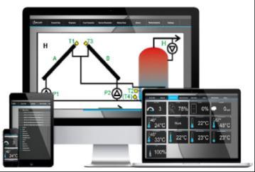
25 15. ACCESS TO THE UNIT OVER THE INTERNET By using an additional module - econet300, the unit enables remote access to its data over a Wi-fi or LAN network. The interface is operated by an ordinary search engine installed in any stationary and mobile communication devices. Pumps are stopped after switching off the controller Basic data reading Fig WWW interface tiles Diagram of active solar circuit system Fig WWW interface- diagram 25


26 15.3. User parameters Fig WWW interface user parameters Service parameters Fig WWW interface - service parameters 26


27 15.5. Heat yield graph Fig WWW interface - heat yield graph Network settings Fig WWW interface - network settings screen 27
28
29 INSTALLATION MANUAL PCSol 300
30 16. TECHNICAL DATA Measurement inputs (low-voltage) Other inputs/outputs: (low-voltage) High-voltage outputs: Collector temperature input (T1) Temperature input (T2) Temperature input (T3) Temperature input (T4) Communication port RS485 Output (H) 5-6V/0,1A (DC) Output P1: 230V/ max 0,5A (AC) Output P2: 230V/ max 0,5A (AC) Power supply: Controller: 230V(AC), 50Hz. I=1.02A* Load ability P1,P2: not more than 0.5A(AC)/output Operating conditions 0 Ta 40 C, humidity 10-90%, without condensation Protection degree IP 20 Weight ~280g * Power intake only by controller is 0.02A, 1,5W Table of temperature measurement accuracy: Internal structure Pt1000 class B (CT6 and CT6w) Temperature ranges Temperatur C C e ranges Accuracy* ±2 C Accuracy* ±2 C T1 (T3**) Displayed range Displayed range T2, T3, T4 * at ambient temperature of 23 C ** in scheme H Elements of the set - Controller PCSol Temperature sensor T1 (CT6w) - Temperature sensor T2 T4 (CT6)* - Operating and installation manual *To use solar thermal scheme B, C, E, F it is required to purchase one additional CT6 sensor. * To use solar thermal scheme D, G, K it is required to purchase two additional CT6 sensors * To use solar thermal scheme H, L it is required to purchase one additional CT6W sensor. *To use heat output function it is required one additional CT6 sensor (Note: does not apply to schemes D, G, K in which heat output is not counted). 17. INSTALLATION OF PCSol pc. 1 pc. 1 pc. 1 pc. The controller is designed for operation in the environment where only dry conductive contaminations may be present (2 degree of contamination according to PN-EN ). In addition, the controller may not be used in water condensation conditions and it may not be exposed to water. The unit software does not ensure required protection level that must be assured by external protections of the solar system Installation of the controller The controller is designed for vertical wallmounted installation. External circuit wires are supposed be lead on surface. Mounting hole locations are presented as in the casing. Hole spacing dimensions are presented also in Fig Wires that enter the controller must be secured at entry locations. Before opening the unit casing, disconnect power supply. The unit installation must be done at disconnected voltage. The unit has any fuse replaceable by the installer or use. If the fuse was burnt during installation or operation, it means damage of the unit. Send the unit to authorized service for repair. Controller must be installed by qualified and authorized technichian in accordance with EN standard. For how to open the unit casing see the picture below. 30


31 The controller must be installed in a way that: it is securely mounted on flat base, using all mounting points (3 in controller casing itself and 4 intermediate plate); degree of protection is ensured suitably to environmental conditions; dust and water access is prevented; Fig Casing opening permissible operating temperature is not exceeded for the controller (40 C); air exchange inside casing is allowed; access to dangerous parts is disabled; electrical installation, to which the controller is connected, must be equipped with the device that allows disconnection of both supply poles, in accordance regulations that applies to such systems. Fig Controller on-wall mounting 31
![Supply L Supply N Pump P1 [L] Pump P1 [N] Pump P2 [L] Pump P2 [N] Output H [+] Output H [-] Sensor T1 [+] Sensor T1 [-] Sensor T2 [+] Sensor T2 [-] Sensor T3 [+] Sensor T3 [-] Sensor T4 [+] Sensor T4](/docs-images/75/72332310/images/32-0.jpg "[-] 17.2. External circuits connection. Fig. 17.3 Controller inside view with terminals 17.2.1. Use of connectors The controller is provided with spring loaded terminals suitable for reception of wire with an end sleeve.")

32 Supply L Supply N Pump P1 [L] Pump P1 [N] Pump P2 [L] Pump P2 [N] Output H [+] Output H [-] Sensor T1 [+] Sensor T1 [-] Sensor T2 [+] Sensor T2 [-] Sensor T3 [+] Sensor T3 [-] Sensor T4 [+] Sensor T4 [-] External circuits connection. Fig Controller inside view with terminals Use of connectors The controller is provided with spring loaded terminals suitable for reception of wire with an end sleeve. The table below includes permissible size ranges for wires connected to the controller terminals: Circuit type Wire cross-section Power supply circuits mm 2 * Low-voltage circuits 0,25 0,75mm 2 * For installations with bare wire cables the maximal size is 1.5mm 2 For good connection between the terminal and cable, insulation and sleeve free length should be in the range of 8 10mm. To place wire in terminal press the terminal push with a flat screwdriver, insert the wire end (with a sleeve on) and then release the push. 32 Fig Using clamped terminals
![Supply L Supply N Pump P1 [L] Pump P1 [N] Pump P2 [L] Pump P2 [N] Supply L Supply N Supply L Supply N Pump P1 [L] Pump P1 [N] Pump P2 [L] Pump P2 [N] 17.2.2. Power supply connection The controller is designed for supply voltage 230V~, 50Hz.](/docs-images/75/72332310/images/33-0.jpg "Supply is connected to terminals L, N. Electric connection diagram is presented in Fig. 17.5. and Fig. 17.6.")


33 Supply L Supply N Pump P1 [L] Pump P1 [N] Pump P2 [L] Pump P2 [N] Supply L Supply N Supply L Supply N Pump P1 [L] Pump P1 [N] Pump P2 [L] Pump P2 [N] Power supply connection The controller is designed for supply voltage 230V~, 50Hz. Supply is connected to terminals L, N. Electric connection diagram is presented in Fig and Fig V supply wires must be lead so as their contact with sensor and other low-voltage cabling is prevented, additionally, all cables may not contact surfaces with temperatures that exceed the cables operating temperature limits. The controller has no PE protective connector, because the controller itself does not require grounding. PE terminals of the pump shall be connected with PE of supply network, according to periphery instructions and regulation concerning electric systems. Proper electric installation method is responsibility of the electrician. It is recommended to connect PE circuits through external screw connector, as presented in diagrams. Pump P2 is connected analogically as pump P1. Supply Fig Electro-valve connection Scheme L The connection shown in fig requires electro-valve coil adjusted to ~230 voltage Temperature sensor connection Fig Power supply connection Sensors are provided with two wires: CT6w 1m long, silica wire; CT6 2m long. If you need longer cables, use mm 2 cable not longer than 30 meters, and connection points must secured against short circuit and humidity. Take a note that when extending the line with additional wire the sensor circuit resistance increases and it may cause errors in measurement. Such errors may be adjusted by the wire length compensation function described in menu I/O Configuration. Compensation method is described in section Supply CT6w sensor is provided with special high-temperature silica cables, it must not be replaced with CT6 sensor, because of possible insulation damage when the collector temperature is high. Fig Connection of pumps 33
![Sensor T1 [+] Sensor T1 [-] Sensor T2 [+] Sensor T2 [-] Sensor T3 [+] Sensor T3 [-] Sensor T4 [+] Sensor T4 [-] Table of sensor resistance against temperature: temperature resistance -25 ºC -20 ºC](/docs-images/75/72332310/images/34-0.jpg "-10 ºC 0 ºC 10 ºC 20 ºC 25 ºC 30 ºC 40 ºC 50 ºC 60 ºC 70 ºC 80 ºC 90 ºC 100 ºC 110 ºC 120 ºC 130 ºC 140 ºC 150 ºC 160 ºC 170 ºC 901,9 Ω 921,6 Ω 960,9 Ω 1000,0 Ω 1039,0 Ω 1077,9 Ω 1097,3 Ω 1116,7 Ω")
34 Sensor T1 [+] Sensor T1 [-] Sensor T2 [+] Sensor T2 [-] Sensor T3 [+] Sensor T3 [-] Sensor T4 [+] Sensor T4 [-] Table of sensor resistance against temperature: temperature resistance -25 ºC -20 ºC -10 ºC 0 ºC 10 ºC 20 ºC 25 ºC 30 ºC 40 ºC 50 ºC 60 ºC 70 ºC 80 ºC 90 ºC 100 ºC 110 ºC 120 ºC 130 ºC 140 ºC 150 ºC 160 ºC 170 ºC 901,9 Ω 921,6 Ω 960,9 Ω 1000,0 Ω 1039,0 Ω 1077,9 Ω 1097,3 Ω 1116,7 Ω 1155,4 Ω 1194,0 Ω 1232,4 Ω 1270,7 Ω 1309,0 Ω 1347,1 Ω 1385,0 Ω 1422,9 Ω 1460,7 Ω 1498,3 Ω 1535,8 Ω 1573,2 Ω 1610,5 Ω 1647,7 Ω Fig Connection of temperature sensors* *Sensor s function may differ from the drawing depending on selected scheme Temperature sensor installation Temperature sensors are equipped with brass coat with diameter of 6mm and 50mm long. They should be installed possibly close to the temperature measurement point. The sensors must be installed so that the brass coat is thermally insulated from the environment. The collector temperature sensor must be located in the collector tube possibly deep, as this is conditional for correct measurement. If you need mount your sensor on pipe surface (e.g. CH temp. measurement), then the sensor coat must be attached using a brace, and the jointing point to insulate e.g. with foam or other insulating material, so that there is sufficient temperature convection to the sensor. Insulating material Pipe Brace Fig Sensor installation on pipe surface Output H connection Output H is adapted to connect relay supplied with voltage of 5 6V (with coil resistance not lower than 60Ω) and power up to 0.5W. Heater For a heater connection, use relay connected as shown in Fig Wire that connects the controller and transmitter must not have resistance bigger than 1Ω (see Table of wire lengths and resistances in the section on wire length compensation ). The reservoir heater must be connected through a relay with maximal contact current not lower than the heater s nominal current. Recommended relay type is Finder that has load ability of 2x10A. It is suitable for heater control (resistance loads) with power up to 2.5k VA. The relay together with a base is available as accessories. If you choose to use other relay, check its technical parameters and if it meets safety standards. Current received by a receiver may not be higher than nominal current of the relay load. Otherwise, it may be damaged and in extreme case it may cause damage to solar or heating system. 34
![Output H [+] Output H [-] Output H [+] Output H [-] Supply Supply 230~ Receiver Fig. 17.10 Connection of relay to H output.](/docs-images/75/72332310/images/35-0.jpg "Three-way switching valve The output may be used for a three-way switching valve that is controlled: 1.")
: Neutral conductor is connected directly to the valve, while wires that control direction of rotations are connected via a relay and its contacts to")
35 Output H [+] Output H [-] Output H [+] Output H [-] Supply Supply 230~ Receiver Fig Connection of relay to H output. Three-way switching valve The output may be used for a three-way switching valve that is controlled: 1. Unipolarly with return spring: such valve connect to H output of the controller through a relay, like in Fig Bipolarly, right-left rotations (3-wire control): Neutral conductor is connected directly to the valve, while wires that control direction of rotations are connected via a relay and its contacts to relevant terminals. Status relations on H outlet and respective direction of the valve switching are presented in application schemes. Change of rotation direction switching will cause incorrect operation of the unit. Fig Connection of three-way, bipolarly controlled valve to H output If the valve has grounding terminal, connect it directly to the valve. Connection of other valve types than specified above may lead to undesired operation and is not recommended. 35

36 econet internet module connection econet300 module can be connected to the Internet in two ways: over Wi-fi to the local access point, directly through Ethernet cable for LAN network. The most convenient way of connection is recommended. Both ways offer the same operation functions of the controller. PCSol300 Fig Internet connection structure 36
.")
37 18. APPLICATION SCHEMES Solar Application scheme A Loading of DHW reservoir from collector. Fig Schemat aplikacyjny A Installation notes 1. For the controller to count heat output, install additional CT6 sensor on the outlet of lower pipe coil from DHW reservoir and connect to T4 input (or T3 for Basic). The sensor must be installed possibly near the connector pipe. 2. T3 sensor shows temperature in upper part of the reservoir, its connection is not required. In Basic version it is used only for heat output counting. 37

38 18.2. Solar Application scheme B Loading of DHW reservoir from solar panel with additional function of extra heating with a heater, when the solar panel stops supplying energy and with control of DHW circuit with circulation pump. In this layout, it is required to connect T3 sensor and it must be installed in the reservoir over a heater. If T3 is disconnected from the controller or damaged, it will disable reservoir extra heating function. How to connect H output to a heater via a relay is presented in details in section Fig Application scheme B Installation notes 1. For the controller to count heat output, install additional CT6 sensor on the outlet of lower pipe coil from DHW reservoir and connect to T4 input. The sensor must be installed possibly near the connector pipe. 2. T3 sensor is used for controlling additional heat source (H output). Disconnection of the sensor will disable H output and the algorithm of the reservoir loading from collector will work normally. 38

39 18.3. Solar Application scheme C Loading of DHW reservoir from a solar panel with additional function of heat discharge to drain system, when the reservoir maximal temperature (TDHWmax) is exceeded. In this layout, T3 sensor is optional and its connection is not required. Electro-valve must be connected to P2 pump outlet. Fig Application scheme C Installation notes 1. For the controller to count heat output, install additional CT6 sensor on the outlet of lower pipe coil from DHW reservoir and connect to T4 input. The sensor must be installed possibly near the connector pipe. 2. T3 sensor shows temperature in upper part of the reservoir, its connection is not required. 3. Circulation pump is connected to H output through a relay with contact current not lower than the current of the circulation pump. It is recommended to use relays with two switching tracks, see details in section Output H output. 4. Discharge valve coil connected to P2 output must by adjusted to ~230 voltage, see fig. Fig. 18.3, otherwise the valve should be controlled indirectly by an additional transmitter. Setting notes 1. Heat discharge valve works until T2 drops below TDHWmax-HP2. Do not set HP2 value too high as this result in large heat discharges. 39

40 18.4. Solar Application scheme D Loading of DHW reservoir from a solar panel and transfer of accumulated heat to the reservoir B. Fig Application scheme D Installation notes 1. This scheme requires two additional CT6 sensors. 2. Circulation pump is connected to H output through a relay with contact current not lower than the current of the circulation pump. It is recommended to use relays with two switching tracks, see details in section Output H. Setting notes 1. Do not set HP2 value higher or equal to dtab, because this will prevent loading stop when dtab value is reached. 2. With respect to night cooling mode used for the reservoir A and circulation activation for better discharge of the container, it is recommended that circulation circuit is installed in the reservoir A. 40

41 18.5. Solar Application scheme E Loading of two DHW reservoirs (A and B) with loading priority for reservoir A. Fig Application scheme E Installation notes 1. For the controller to count heat output, it is required to install additional CT6 sensor outside circuits of pumps P1 and P2 and connect it to T4 input. The sensor should be installed possibly close to the P1 and P2 pump outlet. 2. Circulation pump is connected to H output through a relay with contact current not lower than the current of the circulation pump. It is recommended to use relays with two switching tracks, see details in section Output H. 3. In the diagram the circulation pump is located on B tank, but its operation is not related with the algorithm and it may be installed on A tank as well. 4. With respect to night cooling mode used for the reservoir A and circulation activation for better discharge of the container, it is recommended that circulation circuit is installed in the reservoir A. 41

42 18.6. Solar Application scheme F Heating of DHW reservoir and pool with Priority function. Fig Application scheme F Installation notes 1. For the controller to count heat output, install additional CT6 sensor outside circuits of three-way valve H and connect it to T4 input. The sensor should be installed possibly close to the H outlet. 2. The valve should be connected so that the controlled relay connected to output H (H=ON) set will set the valve in pool loading position. Reverted connection will damage the system. Setting notes 1. If the used three-way valve has switching time longer than 120sec, set maximal value for tvalve. 2. If the used three-way valve has near zero switching time, set minimal value for tvalve 3. When the circuits are being switched (tvalve time) the collector pump is not working and the circuit receives no heat. Pay attention to collector heat up time and if required set shorter tvalve time. 4. During anti-freeze function, the exchanger pump will work longer than the collector pump by double tdly time. So select this parameter value that after P2 is stopped, the temperature of glycol in exchanger is not lower than 0 C, as it may damage the exchanger. If there is a risk that such situation may happen, switch off antifreeze function for the pool system. Antifreeze function in pool circuit (with priority) may be used only at high awareness. Wrong settings or unfavorable conditions may damage the exchanger. Always consider all factors like, e.g., solar work fluid with below-zero temperature in the exchanger. 42

43 18.7. Solar Application scheme G Loading of DHW reservoir with solar collector and boiler. Fig Application scheme G Installation notes 1. Circulation pump is connected to H output through a relay with contact current not lower than the current of the circulation pump. It is recommended to use relays with two switching tracks, see details in section Output H. 43

44 18.8. Solar Application scheme H Loading of DHW reservoir from two sets of solar collectors oriented in two directions. Fig Application scheme H Installation notes 1. For correct operation the system must be equipped with return valves mounted on the solar panel outlets. In other case, starting circuit of A collector will affect operation of B collector sensor, causing poor performance. 2. For the controller to count heat output, install additional CT6 sensor on DHW reservoir lower pipe coil and connect it to T4 input. The sensor must be installed possibly near the connector pipe. 3. Circulation pump is connected to H output through a relay with contact current not lower than the current of the circulation pump. It is recommended to use relays with two switching tracks, see details in section Output H. Setting notes 1. With the use of additional sensor T4, the controller allows effective controlling of P2 pump that will be started, when the temperature of return from exchanger reaches dtp2 value. 44

45 18.9. Solar Application scheme I Loading of pool system from solar collector. Fig Application scheme I Installation notes 1. For the controller to count heat output, it is required to install additional CT6 sensor directly on the return from the pool exchange, and connect it to T4 measurement input. Setting notes 1. With the use of additional T4 sensor, the controller allows effective controlling of P2 pump that will be started, when the temperature of return from exchanger reaches dtp2 value. 2. At long pipe lengths (between collector and exchanger), setting of dtp2 value lower than it results from losses incurred in the collector-exchanger section will prevent starting of P2 pump, even at high temperatures in the collector. This setting must be selected specifically to each installation. 3. During anti-freeze function, the exchanger pump will work longer than the collector pump by double tdly time. So select this parameter value that after P2 is stopped, the temperature of glycol in exchanger is not lower than 0 C, as it may damage the exchanger. If there is a risk that such situation may happen, switch off antifreeze function for the pool system. Antifreeze function in pool circuit (with priority) may be used only at high awareness. Wrong settings or unfavorable conditions may damage the exchanger. Always consider all factors like, e.g., solar work fluid with below-zero temperature in the exchanger. 45

46 Solar Application scheme J Collector operation with additional back-up source. Fig Application scheme J Installation notes: 1. For the controller to count heat output, it is required to install additional CT6 sensor directly on the return from the DHW reservoir lower pipe coil and connect it to T4 measurement input. 2. Circulation pump is connected to H output through a relay with contact current not lower than the current of the circulation pump. It is recommended to use relays with two switching tracks, see details in section Output H. 46

47 Solar Application scheme K Charging A Buffet with a solar panel. Container-in-container type buffer. The regulator supports CH system. Fig Application scheme K *Pumps marked in the scheme as P are not controlled by BLUESol 02 regulator. Installation instructions 1. Two additional CT6 sensors are required for the application schema. 2. Connect the circulation pump to H output via a transmitter with connector voltage not lower than circulation pump voltage. It is recommended to use transmitters with two switching circuits. Details can be found in chapter Connecting H output. Setting notes 1. Do not set HP2 value higher or equal to dtab, because this will prevent loading stop when dtab value is reached. 47
![Supply L Supply N Pump P1 [L] Pump P1 [N] Pump P2 [L] Pump P2 [N] Output H [+] Output H [-] Sensor T1 [+] Sensor T1 [-] Sensor T2 [+] Sensor T2 [-] Sensor T3 [+] Sensor T3 [-] Sensor T4 [+] Sensor T4](/docs-images/75/72332310/images/48-0.jpg "[-] 18.12. Aplikacja schemat solarny L DHW tank is loaded by two solar collector sets oriented towards two points of compass using one pump group and collector circuit switching valve.")

48 Supply L Supply N Pump P1 [L] Pump P1 [N] Pump P2 [L] Pump P2 [N] Output H [+] Output H [-] Sensor T1 [+] Sensor T1 [-] Sensor T2 [+] Sensor T2 [-] Sensor T3 [+] Sensor T3 [-] Sensor T4 [+] Sensor T4 [-] Aplikacja schemat solarny L DHW tank is loaded by two solar collector sets oriented towards two points of compass using one pump group and collector circuit switching valve. Mains 230V~ Fig Application scheme L Installation notes 1. 3-way/1-way control valve was considered in this diagram. Valve is switched back by means of a spring. Other valves may be controlled using relays as shown in Fig The valve should be so installed that high state of P2 output sets the flow in direction of A-solar collector. 3. The valve may be connected to solar collector supply.. Valve way is as shown in item To enable calculation of heat yield by the regulator: install additional CT6-type sensor at the outlet of lower pipe coil from DHW tank and connect it to T4 input. The sensor should be mounted as close as possible to the outlet of pipe coil from DHW tank. 5. Connect circulating pump to H-output through relay of contact current not less than the current of the pump. It is recommended to use relays with two switching channels for details see section Output H. 6. Setting recommendations 7. During interim periods, when sunlight falls on both solar collectors and the collector currently not in use becomes overheated, reduce the set top time. 48


49 19. CASING CLOSING To close the unit casing hook the casing cover with recesses against the base insets (shown in Fig. 19.1) 20. CONTROLLER OPTIONS Access Access to the controller options is protected with password and to make any changes you must log-in with a service password. Fig Casing closing first step Then, press the cover in place indicated by red arrow (Fig. 19.2), until you clearly hear the latch click. Fig User login screen To login place cursor in selected digit by its rotating, then press the button. When the digit is blinking, rotate the encoder to change its value. Confirm the digit by pressing again. Edition will move the cursor to next position. Confirm login by using OK" or abandon login by using CANCEL option. If the password is wrong, the unit will display a message Fig Fig Information on incorrect password Repeat login procedure. Fig Casing closing second step Settings should be modified only by trained persons with adequate technical skills. Wrong parameters may cause irregular performance or damage to the equipment. 49
50 20.1. System Options\Settings The following settings are available depending on scheme and version: PCSol 300 Setting A B C D E F G H I J K L dtondhw X X X X X X X X X X X dtoffdhw X X X X X X X X X X X dtonpool X X dtoffpool X X TCOLmin TCOLcr TCOLmax X X X X X X X X X X X X X X X X X X X X X X X X X X X X X X X X X X X X TDHWmax X X X X X X X X X X X Pmin tp HP1 HP2 tvalve X X X X X X X X X X X X X X X X X X X X X X X X X X X X X X X X X X X X X X X X X X X X X X X tdly X X X TCOmin dtp2 Settings description dtondhw - temperature difference between T1 (T3 in scheme H) and T2 (T3 in scheme E) that will the collector pump P1 or P2 at 100% capacity. dtoffdhw - temperature difference between T1 (T3 in scheme H) and T2 (T3 in scheme E), at which the pump will work with minimal capacity Pmin. Below this value, the collector pump is stopped. It will be restated when dtondhw value is reached. dtonpool in schemes with pool system, temperature difference between T1 and T3 (for scheme F) and T1 and T2 (for scheme I), which starts P1 pump at 100% capacity. dtoffpool - temperature difference between T1 and T3 (for scheme F) and T1 and T2 (for scheme I), at which the pump will work with minimal capacity Pmin. Below this value, the collector pump is stopped. It will be restated when dtonpool value is reached. TCOLmin - minimal collector temperature, which must be reached to allow reservoir loading. If the collector temperature has not reached this setting value, despite that loading conditions are met (resulting e.g. from reaching dton) the controller would not start the collector pump. X X X The collector pump will be started only below dtoffdhw or dtoffpool (depending on scheme). TCOLcr collector critical temperature. Temperature which regardless of reaching reservoir preset (TsDHW) or pool preset (TsPOOL) will start the collector pump at 100% capacity in order to discharge heat from the collector. It will be stopped when the collector temperature drops below TCOLcr-HPx (where x means the number of collector pump: 1 or 2). If AlarmTCOLcr setting has YES value, the unit displays alarm on exceeding critical collector temperature. This alarm allows starting collector pump, only when the system with DHW reservoir is not in condition of exceeded reservoir maximal temperature TDHWmax alarm. TCOLmax reaching this collector temperature will stop the collector pump. The controller reports alarm. The collector pump may be started only when the collector temperature drops below the temperature difference TCOLmax-HPx. The controller dynamically limits minimal value of TCOLmax setting and maximal value of TCOLcr setting, so that set values give interval between TCOLcr and TCOLmax not lesser than 30 C. This protects from impulse increase of the collector temperature when the collector pump is started, after TCOLcr is reached. To set higher TCOLcr than allowed by the controller, increase TCOLmax value, so that the interval condition of 30 C is maintained. - DHW reservoir maximal temperature that stops collector pump and disables further loading of the reservoir. Alarm on exceeding DHW reservoir maximum temperature is displayed. This alarm has higher priority than alarm on TCOLcr and despite the alarm on collector critical temperature; the controller will disable starting the collector pump for the reservoir. Alarm will be stopped and the pump start released, when the reservoir temperature drops below TDHWmax-HPx. Pmin minimal capacity of the collector pump reached if the difference between collector and reservoir temperatures drops to dtoffdhw or dtoffpool value (depending on scheme). 50
51 tp Minimal time of the collector pump work. If the difference between collector and reservoir temperatures drops to dton, the collector pump will be started for the time of tp. HP1- auxiliary hysteresis for P1 output. HP2 - auxiliary hysteresis for P2 output. Too high values of HP1, HP2 settings may lead to large temperature oscillations in the system, so it is recommended to leave them at the level of 1 C. tvalve minimal operation time of the controller s valve that switches the circuits (used in solar application F). tdly time of delay for switching on/off the pump downstream heat exchanger. TCOmin minimal temperature in CH circuit (measured by T4 sensor) in scheme G, which allows loading of DHW reservoir from the boiler system. Below this temperature (even if there are conditions for reservoir loading, i.e. TsDHW is lower than preset or dtco is reached), the controller will disable the reservoir loading. This prevents CH circuit operation below the boiler s dew point. dtp2 temperature difference between T1 collector and T4 exchanger, if reached the controller will start exchanger pump in scheme I. Operation with tdly is also possible, then dtp2 setting must set as OFF. At such setting, the controller will run P2 operational algorithm with delay of tdly in relation to P1 pump operation. Alarm from T4 sensor will not be reported I\O Options\Configuration Depending on the length of sensor extension cable, sensors will show temperature without taking into account resistance of connection lines. To compensate cable effects, it is required to perform sensor compensation procedure Wire length compensation It consists in measurement of wires connected to a sensor (measurement track), reading value from the compensation table for connecting wire resistance, and programming this value in the controller. The controller will automatically move sensor s characteristics to compensate the effect of additional resistance. When you enter menu, the controller displays current values of temperature corrections. If the controller displays 0.0, it means that no correction has been introduced for given track. To clear any compensation data for the track, enter 0.0 value. The procedure may be conducted using ohmmeter to measure resistance of both cable conductors and selecting from the table respective value for measured resistance. If received result indicates correction above 2 C, it may means that the cable have resistance bigger than permissible or that they are too long. Table of cable lengths and resistance. size length 0,5mm 2 0,75mm 2 1mm 2 5m 0,35Ω 0,23Ω 0,18Ω 0,1 C 0,1 C 0,1 C 10m 0,69Ω 0,46Ω 0,35Ω 0,2 C 0,2 C 0,1 C 15m 1,04Ω 0,69Ω 0,52Ω 0,3 C 0,2 C 0,2 C 20m 1,38Ω 0,92Ω 0,69Ω 0,4 C 0,3 C 0,2 C 25m 1,73Ω 1,15Ω 0,87Ω 0,5 C 0,3 C 0,3 C 30m 2,07Ω 1,38Ω 1,04 Ω 0,6 C 0,4 C 0,3 C Options\Functions Depending on scheme and version, the following settings are available in the Functions menu: Setting Antifreeze Work fluid Flow P1 Flow P2 Vac. collector Detect. level Scheme A B C D E F G H I J K L X X X X X X X X X X X X X X X X X X X X X X X X X X X X X X X X X X X X X X X X X X X X X X X X X X X X X X X X X X X X Operation time X X X X X X X X X X X X Antifreeze setting ON enables the antifreeze function. The collector pump will be started, if the solar work fluid temperature drops to the freezing value set for the work fluid. For correct operation of this function, it is required to select suitable solar work fluid. Collector pump will be stopped, if the work fluid temperature rises by 2 C. When the function is off, the controller will not monitor antifreeze and it may lead to damage of the solar system in winter period, so it is recommended that it remains on. In scheme E, antifreeze function operates in the circuit of reservoir A, in scheme F the function operates in priority circuit. If in the system with DHW reservoir the reservoir temperature drops down to 2 C, the X 51
52 controller will alarm that it is not possible to continue antifreeze function. Work fluid type of fluid used in the system. Correct setting is required for good performance of antifreeze function and heat output counting. No. Name Freezing temperature 1 Ergolid EKO -15 C -15 C 2 Ergolid EKO -20 C -20 C 3 Ergolid EKO -25 C -25 C 4 Ergolid EKO -35 C -35 C 5 Ergolid A -15 C -15 C 6 Ergolid A -20 C -20 C 7 Ergolid A -25 C -25 C 8 Ergolid A -35 C -35 C 9 Tyfocor LS -20 C 10 ECO MPG-SOL C 11 ECO MPG-SOL C 12 ECO MPG-SOL C 13 Henock 35P35-35 C Flow P1 flow calibration function required for correct heat output function. Rotometer or water meter must be installed in the sole work fluid circuit. When edition is open (value is blinking), the collector pump P1 will be controlled for maximum capacity. Now, read flow value directly from a rotometer or measure (using water meter) how many liters of work fluid will flow for one minute and program the value to the controller. Correct flow value is needed to correctly count heat output by the controller. Flow P2 P2 pump calibration function for solar scheme H. To calibrate solar work fluid circulation speed, it is required to have rotometer or water meter installed. When edition is open (value is blinking), the collector pump P2 will be controlled for maximum capacity. Correct flow value is needed to correctly count heat output by the controller. Flow calibration P2 is available only in Solar thermal scheme H. For correct heat output counting in scheme H, calibration for both pumps is required. Vac. collector vacuum collector function on/off. The function principle of operation is described in section Detect. level setting that defines how much the collector temperature must rise (at started vacuum collector function) in one minute, to activate the collector pump. Operation time time to stop the collector pump, after the temperature set in Dect. level is reached Vacuum collector function Settings needed for the vacuum collector function are described previous section. The vacuum collector function (when enabled) checks the collector temperature and starts the collector pump, if after one minute the collector temperature will increase by level set in Detection level; the collector pump will be started for the time set for Operation time. After this short impulse, unless normal conditions for starting collector pump occur, the controller will continue checking the collector s temperature. The vacuum collector function is disabled, if the collector temperature is below 0 C and there are alarm active that block the collector pump operation Manual mode Manual mode allows manual controlling for outputs: P1, P2, H. Outputs are controlled directly after the setting value edition is confirmed. From this menu the controller will not return to main screen automatically. After you leave manual mode, the controller returns to output controlling in accordance with operating algorithm. In the manual mode all automatic actions are stopped. Leaving the controller in this mode for longer time may damage the system Scheme wizard Scheme wizard is to select type of installation. It is done by turning the knob to browse through schemes. Number and type of schemes depend on the controller version. After selection, the controller will request to confirm the scheme. 52

53 21. FUSE REPLACEMENT Cut off power supply to the controller before fuse replacement. A 1.25A time-delay subminiature fuse with minimum interrupting current of 100A should be used, as per IEC standard. An example of a fuse meeting the requirements is Schurter MXT-250 time-delay fuse. To replace, open controller's enclosure and replace burnt fuse with a new one (Fig. 21.1). The manufacturer reserves the right to make changes in design and software without prior notice. Fig Fuse replacement Record of changes 3.X.1 z dn First edition 53
Room panel. for ecomax800 R or T regulators. OPERATION AND MAINTENANCE MANUAL ISSUE: 1.3 APPLICABLE TO SOFTWARE: v , v , v08.21.
 Room panel ecoster 200 for ecomax800 R or T regulators OPERATION AND MAINTENANCE MANUAL ISSUE: 1.3 APPLICABLE TO SOFTWARE: v08.21.014, v08.21.015, v08.21.016 2010-08-31 TABLE OF CONTENTS 1. SAFETY...
ST 53.1 User s manual
 Tech - 1 - ST 53.1 User s manual Table of contents I. Safety... 3 II. Description... 4 III. Installation... 4 IV. Operating the Controller... 6 IV.a) Principle of Operation... 6 IV.b) Control... 6 V. Controller
HIGH EFFICIENCY FIRETUBE CONDENSING GAS BOILER
 This manual must be left with owner and should be hung on or adjacent to the boiler for reference. US HIGH EFFICIENCY FIRETUBE CONDENSING GAS BOILER MODELS CHS-85 through CHS-399 APPENDIX A CONTROLLER
1 DOCUMENT REVISION SOFTWARE VERSION BASIC DESCRIPTION BASIC OVERVIEW OF HYDRAULIC DIAGRAMS HYDRAULIC DIAGRAMS...
 User Manual Contents 1 DOCUMENT REVISION... 4 2 SOFTWARE VERSION... 4 3 BASIC DESCRIPTION... 4 4 BASIC OVERVIEW OF HYDRAULIC DIAGRAMS... 5 4.1 BOILER NOT CONTROLLED BY THE CONTROLLER:... 5 4.2 BOILER CONTROLLED
Mounting and Operating Instructions EB 5610 EN. TROVIS 5600 Automation System TROVIS 5610 Heating and District Heating Controller
 TROVIS 5600 Automation System TROVIS 5610 Heating and District Heating Controller Mounting and Operating Instructions Electronics from SAMSON EB 5610 EN Firmware version 1.40 Edition December 2014 Controller
CSP-204 CSP-208 CSP-104 CSP-108
 Fire Alarm Control Panel CSP-204 CSP-208 CSP-104 CSP-108 Operation manual Firmware version 1.1 csp-x_o_en 06/15 SATEL sp. z o.o. ul. Budowlanych 66 80-298 Gdańsk POLAND tel. 58 320 94 00 www.satel.eu CONTENTS
ecomax 800, model R1 Boiler regulator Dzia Zintegrowanego Systemu Zarz dzania version: ec FOR SOLID FUEL-FIRED BOILERS WITH FEEDING SCREW
 Boiler regulator ecomax 800, model R1 version: ec Dzia Zintegrowanego Systemu Zarz dzania FOR SOLID FUEL-FIRED BOILERS WITH FEEDING SCREW SERVICE AND ASSEMBLY MANUAL ISSUE: 1.2 APPLICABLE TO SOFTWARE:
Installation and user manual
 Installation and user manual Please read carefully and retain for future reference Models EcoHeat: C3, C5, C6, C8, C9, C11, C12 Rev.1_09-07-15 Page 1 Table of Contents 1 IMPORTANT: WARNINGS 1.1 GENERAL
OPERATION MANUAL RK-2006LPP AUGER FITTED SOLID FUEL BOILER TEMPERATURE CONTROLLER. Version DC19
 OPERATION MANUAL RK-2006LPP AUGER FITTED SOLID FUEL BOILER TEMPERATURE CONTROLLER Version DC19 1. Application. Controller RK-2006LPP is designed for temperature control of solid fuel fired water boilers
SOLARCOMP 951 CONTROLLER FOR SOLAR COLLECTORS
 SOLARCOMP 951 CONTROLLER FOR SOLAR COLLECTORS Installation and Operating Instructions for model u7.x, Rev. 1, April 2014 Pb Safety Instructions Before installation read these Operation and Installation
Phone-A-Stat. MODEL Command Center With Thermostat Operation, Maintenance & Installation Manual. Introduction.
 Introduction The UL listed Phone-A-Stat (model # 7632 ) is designed and approved for the safe operation of remotely controlling four independent loads, such as a sprinkler system or a water heater via
Dryer Controller M720
 User Manual Dryer Controller M720 Hardware version 2.00 Software version 2.00 Manual M720 Dryer controller Page 1 of 60 Document history Preliminary version: - Created in April, 2009 Hardware Version 2.00,
ecomax 200 W Boiler regulator FOR SOLID FUEL BOILERS WITH A FAN OPERATION AND MAINTENANCE MANUAL ISSUE:
 Boiler regulator ecomax 200 W FOR SOLID FUEL BOILERS WITH A FAN OPERATION AND MAINTENANCE MANUAL ISSUE: 1.3 APPLICABLE TO SOFTWARE 10.034 10.035 10.036 2010-04-14 TABLE OF CONTENTS 1 Safety... 4 2 General
Electronic Pellet Burner Controller NPBC-V3-1
 Electronic Pellet Burner Controller NPBC-V3- SOFTWARE VERSION 3.2/3. page of 3 CHANGES IN THE TECHNICAL AND USER GUIDE OR IN THE SOFTWARE VERSION Technical and User Guide's version Changes Page 2.8. The
ENERGY LIGHT USER S GUIDE ENERGY LIGHT USER S GUIDE
 ENERGY LIGHT USER S GUIDE Release January 2001 CONTENTS 1.0 GENERAL CHARACTERISTICS... 4 1.1 MAIN CHARACTERIS TICS... 4 2.0 USER INTERFACE (CODE C5121230)... 5 2.1 DISPLAY... 5 2.2 MEANING OF THE LEDS...
Declaration of Conformity No. 27/2008
 ST-44 USER S MANUAL ST-45 User's Manual Declaration of Conformity No. 27/2008 Hereby, we declare under sole responsibility that the ST-45 230V 50Hz thermoregulator manufactured by TECH, ul. St. Batorego
OUMAN EH-800 Heating controller USER MANUAL
 OUMAN EH-800 Heating controller USER MANUAL 1 EH-800 is a heating controller for private homes and business facilities having heating systems with circulating water. An extension unit can be obtained as
BOILER CONTROLLER COMPACT
 BOILER CONTROLLER COMPACT page 2 Index Index 1 General information 5 1.1 Introduction 5 1.2 Features 5 1.3 Safety precautions 7 1.4 Disposal of old equipment 8 2 Connecting to the system 9 2.1 General
User Manual. Dryer Controller M720
 User Manual Dryer Controller M720 Hardware version 1.00 Software version 1.00 Preliminary version Manual M720 Dryer controller Page 1 of 42 Document history Preliminary version: - Created in April, 2009
CLEVER CONTROL Version: V3
 CLEVER CONTROL Version: V3 INSTALLATION AND FUNCTIONING MANUAL USER AND BASIC VERSION Please, read these instructions carefully before attempting installation SECURITY ADVISE SIMBOLS Attention, Danger,
Vokèra OpenTherm 711 without external sensor connected
 Vokèra OpenTherm 711 without external sensor connected Setup guide to using the OpenTherm Control without an external weather compensation sensor fitted. If you are unsure if there is an external sensor
INSTRUCTION MANUAL OF THE SIEMENS CLIMATIX 2 CONTROL EQUIPMENT
 Instruction manual of the control equipment Program version: 2014-01-17 Benekov 04.00 C L I M A T I X 2-1 - CONTENTS 1. Introduction... 3 1.1. TERMINOLOGY AND ABBREVIATIONS... 3 1.2. NUMBER OF HEATING
Vokèra OpenTherm 711 with external sensor connected
 Vokèra OpenTherm 711 with external sensor connected Setup guide to using the OpenTherm Control with an external weather compensation sensor fitted. If you are unsure if an external sensor is fitted check
General information. Technical data...2 General information...2. Description. Installation
 user manual Table of contents Technical data Technical data...2 General information...2 Installation...3 Navigation...3 First run...4 Main screen...6 Main menu...6 Time...7 Date...7 Calendar...7 Language...10
TECH. Declaration of conformity no 23/2007
 ST-81 USER'S MANUAL TECH Declaration of conformity no 23/2007 We, company Tech, ul. St. Batorego 14, 34-120 Andrychów declare with full responsibility that ST-81, 230 V, 50 Hz thermo regulator that we
BM Programming Module. For the heating engineer Installation instructions
 For the heating engineer Installation instructions BM Programming Module WOLF GmbH Postfach 1380 84048 Mainburg Tel. 08751/74-0 www.wolf-heiztechnik.de Document no.: 3062612_201509 Subject to modifications
Lago SD3. Differential Controller with Speed Control. Operating and Installation Instructions
 Lago SD3 Differential Controller with Speed Control Operating and Installation Instructions Please observe the safety instructions and read through this manual carefully before commissioning the equipment.
Condensing Boiler RS100 Controller Training Program
 Condensing Boiler RS100 Controller Training Program Training Program #501102A 062311 www.rinnai.us 2009 Rinnai America Corporation Features and Benefits The RS100 connects directly to the boiler and acts
Owner s Manual. Part Number 33CSSP2-FC BACK LIT LIQUID CRYSTAL DISPLAY MODE BUTTON
 Owner s Manual Part Number 33CSSP2-FC 33CS Fan Coil Programmable Thermostat SAFETY CONSIDERATIONS Read and follow manufacturer instructions carefully. Follow all local electrical codes during installation.
Programmable Interactive User Manual
 67504B 02/16 (ALA) DH E RT 102/BW Programmable Interactive User Manual www.schluter.com 1. Contents 2. Menu Overview..............3 3. Introduction................ 4 4. General Operation............5 4.1.Navigation
AVANT DGi. Thermal Electric Radiator. Operating and Installation Instructions. (Read these instructions carefully and retain for future reference)
") (v13. 20180906) MODE CONFIG. PROG. AVANT DGi Thermal Electric Radiator Operating and Installation Instructions (Read these instructions carefully and retain for future reference) Models: AVANT-DGi 350
(v13. 20180906) MODE CONFIG. PROG. AVANT DGi Thermal Electric Radiator Operating and Installation Instructions (Read these instructions carefully and retain for future reference) Models: AVANT-DGi 350
USER'S MANUAL PU SENS 01 (A11) PU SENS 01 (A19) Sensor Control Panel
 PU SENS 01 (A19) Sensor Control Panel") USER'S MANUAL PU SENS 01 (A11) PU SENS 01 (A19) Sensor Control Panel PU SENS 01 CONTENTS Safety requirements... 3 Purpose... 4 Technical data... 4 Overall dimensions [mm]... 4 Mounting and set-up... 5
USER'S MANUAL PU SENS 01 (A11) PU SENS 01 (A19) Sensor Control Panel PU SENS 01 CONTENTS Safety requirements... 3 Purpose... 4 Technical data... 4 Overall dimensions [mm]... 4 Mounting and set-up... 5
Monitoring Software for NPBC-V3M-1 User Manual
 Monitoring Software for NPBC-V3M-1 User Manual User Manual ver 1.5 page 1 of 14 Contents: 1. Introduction... 3 2. Requirements... 3 3. Installing the software... 4 4. Connecting the devices... 4 5. Updating
Trinity Tft/Lx Model #s: Tft60-399/Lx Version Date:
 Trinity Tft/Lx Model #s: Tft60-399/Lx150-800 Version Date: 2013-07-26 NEW FEATURES Second Central Heat Input Internal Lead-Lag Control System Sensor Modulation Sensor Alternatives Warm Weather Shutdown
MC200. Users Instructions. HEATING DIVISION Hort Bridge Ilminster, Somerset TA19 9PS Tel: Fax:
 MC200 Users Instructions BSI Registered Firm HEATING DIVISION Hort Bridge Ilminster, Somerset TA19 9PS Tel: 01460 53535 Fax: 01460 52341 FM 414 Ind. & Comm. Air Heaters; Air Moving Equipment; Flues & Chimneys;
Halton SAFE / 7.14 user guide and installation instructions
 Halton SAFE / 7.14 user guide and installation instructions VERIFIED SOLUTIONS BY H A LTO N Enabling Wellbeing Table of contents 1 System description 3 2 User Accounts 4 3 Main menu 7 3.1 Main menu - Change
Electronic Pellet Burner Controller NPBC-V3M
 Electronic Pellet Burner Controller NPBC-V3M SOFTWARE VERSION 3.3a/3.2 page of 27 CHANGES IN THE USER MANUAL OR IN THE CONTROLLER'S SOFTWARE Version of the user manual Changes Page 2.2. The software version
INSTRUCTION MANUAL REMOTE CONTROL DEVICE EASYREMOTE
 INSTRUCTION MANUAL REMOTE CONTROL DEVICE EASYREMOTE Technical features Guide to LCD symbols Guide to keys Technical features Supply by communication bus Number of temperature levels 2 (DAY / NIGHT) Temperature
Sensor Control Panel
 USER S MANUAL PU SENS 01 Sensor Control Panel V55-6EN-03(SENS).indd 1 18.08.2015 10:37:16 2 PU SENS 01 CONTENTS Safety Requirements 2 Main Technical Data 3 Control Panel Mounting 3 Control Panel Operation
Programmable Towel Radiator Manual
 Programmable Towel Radiator Manual Contents Description Page 3 Location Page 4 Mountings Page 5 Starting Up Page 6+7 Return To The Initial Settings Page 8 Time Setting Page 9 Setting The Temperature (Set-Points)
CS027 User Instructions
 CS027 User Instructions Battery Powered 7 Day Programmable Room Thermostat Programmable room thermostats are widely recognised as one of the best ways in which to control central heating. The CS027 programmable
AIR CONDITIONER OPERATING MANUAL. Duct type. Indoor Unit ARTG45LDTA ARTG54LDTA ARTG60LDTA KEEP THIS MANUAL FOR FUTURE REFERENCE. PART No.
 AIR CONDITIONER OPERATING MANUAL Duct type Indoor Unit ARTG45LDTA ARTG54LDTA ARTG60LDTA KEEP THIS MANUAL FOR FUTURE REFERENCE PART No. 98067 98067_OM_EN.indd 07-Aug-5 :40:5 OPERATING MANUAL PART No. 98067
AQUATROL Zone Synchronizing Universal Injection/Mixing Boiler Reset Controls AQ252
 AQUATROL Zone Synchronizing Universal Injection/Mixing Boiler Reset Controls AQ252 USER OPERATION AND MAINTENANCE WARNING Risk of electrical shock. Can cause severe injury, property damage or death. Only
Use of the application program
 Contents overview Use of the application program Use of the application program 1 1. Functional description 2 Switching on / off 2 Dimming brighter / darker 2 Dimming value (8 bit) 3 Status Switching (1
USER MANUAL S203. Controller for three circuits. - control for 2 heating circuits - 1 domestic hot water control. Saving energy, creating comfort
 USER MANUAL S203 Controller for three circuits - control for 2 heating circuits - 1 domestic hot water control Saving energy, creating comfort This user manual consists of two parts. Issues that are intended
GA01HC-02. Service manual. Room Panel. Programme version 01a. Operating with GH07EA regulator for controlling electrode boilers
 Room Panel GA01HC-02 Operating with GH07EA regulator for controlling electrode boilers Programme version 01a Service manual We request that users carefully study applicable Instructions before connecting
ASSEMBLY INSTRUCTIONS FOR THE PUMP AND CONTROL UNIT ZPS 18a-01
 ASSEMBLY INSTRUCTIONS FOR THE PUMP AND CONTROL UNIT ZPS 18a-01 1. Use and construction of the pump and control unit The pump and control unit is designed to work with solar collectors in systems with required
OPERATING INSTRUCTIONS. G214 Software - Version 4
 OPERATING INSTRUCTIONS G214 Software - Version 4 Control Panel (G-214 Controller) 1 2 3 4 5 6 7 8 19 9 10 11 12 13 14 15 16 17 18 Control Panel Description 1. Probe shown in Main screen 2. Probe temperature
Installation & User s Instructions
 Installation & User s Instructions 8 080 shown Part No. 00 day Wired Digital Programmer & Room Sensor Part No. 080 day Wireless Digital Programmer & Room Sensor Part No. 00 hr Wireless Digital Programmer
VERSO-P, VERSO-R Series Air Handling Units with C3 Control System Electrical Installation and Operation Manual
 VERSO-P, VERSO-R Series Air Handling Units with C3 Control System Electrical Installation and Operation Manual EN Table of Contents 1. INSTALLATION MANUAL...3 1.1. Air Handling Units Sections Connection...3
Installation, Programming and Operating Guide for Digital, Programmable Thermostat with Smart Fan Technology. with SFT (Smart Fan Technology )
") with SFT (Smart Fan Technology ) Installation, Programming and Operating Guide for Digital, Programmable Thermostat with Smart Fan Technology EclipseEfficiencies.com 2016 Eclipse Efficiencies, Inc. All
with SFT (Smart Fan Technology ) Installation, Programming and Operating Guide for Digital, Programmable Thermostat with Smart Fan Technology EclipseEfficiencies.com 2016 Eclipse Efficiencies, Inc. All
ROOM THERMOSTAT. with OpenTherm+ communication
 ROOM THERMOSTAT with OpenTherm+ communication PT52 LARGE BACKLIT DISPLAY with intuitive navigation in English 9 WEEKLY PROGRAMS FOR CENTRAL HEATING (C.H.) 6 temperature changes per day 1 WEEKLY PROGRAM
SAT-3 Room Temperature Controller
 SAT-3 Room Temperature Controller USER S OPERATING INSTRUCTIONS Contents Introduction 5 Features Summary 5 Operation 7 On/Off 7 Room Temperature Adjustment 7 Operating Mode Selection 8 Fan Speed Selection
Installation Settings Guide
 In this guide we will describe the advanced installation settings that you can access from KONO Smart s main menu. We recommend that an HVAC service professional uses these settings to fine-tune your thermostat
GH10PA USER MANUAL. Program version 01 MANUAL FOR CONTROLLER FOR CONTROLLING CENTRAL HEATING BOILERS FIRED WITH PELLETS AND OATS
 MANUAL FOR CONTROLLER GH10PA FOR CONTROLLING CENTRAL HEATING BOILERS FIRED WITH PELLETS AND OATS Program version 01 USER MANUAL We request that users carefully study applicable Instructions before connecting
On initial power up the thermostat will guide you through set up procedure for the following:
 Operating Guide: for the Warmup 3iE Programmable Thermostat INTRODUCTION Your thermostat s default screen is the Home Screen. This screen displays important information such as the time, current floor
EUROSTER 11Z CENTRAL HEATING / UTILITY HOT WATER PUMP CONTROLLER
 EUROSTER 11Z USER MANUAL 1 EUROSTER 11Z CENTRAL HEATING / UTILITY HOT WATER PUMP CONTROLLER MANUFACTURER: P.H.P.U. AS, Polanka 8a/3, 61-131 Poznań, POLAND 1 INTRODUCTION Carefully study this user manual
District heating controller
 2 515 District heating controller for 2 heating circuits and d.h.w., communicating RVD260 Multifunctional heating controller for district heat transfer stations and plants with LPB and M-bus communication.
prestige Control Application Supplement - TriMax
 prestige Control Application Supplement - TriMax L I S T E D WARNING This document is intended to be used by a factory trained and qualified heating contractor or service technician only. Read all instructions
Spa Touch Control Panel with BP2100, BP6013 spa controllers. (Spa Owner s Manual insert)
") Spa Touch Control Panel with BP2100, BP6013 spa controllers. (Spa Owner s Manual insert) P.N. 7876C (export) February 12, 2015 For Spas equipped with BP2100, BP6013 controllers and Spa Touch panel. Spa
Spa Touch Control Panel with BP2100, BP6013 spa controllers. (Spa Owner s Manual insert) P.N. 7876C (export) February 12, 2015 For Spas equipped with BP2100, BP6013 controllers and Spa Touch panel. Spa
Declaration of Conformity no. 56/2012
 tech -1- ST 280 Instructions manual Declaration of Conformity no. 56/2012 We, TECH Sp.j., with our registered company office at Wieprz 1047A, 34-122 Wieprz, Poland declare under our full responsibility
WATER HEATER ELECTRONIC CONTROLLER USER MANUAL
 WATER HEATER ELECTRONIC CONTROLLER USER MANUAL UPPER LED READOUT LED ICONS LOWER LED READOUT PVI INDUSTRIES, LLC - Fort Worth, Texas 76111 - Web www.pvi.com - Phone 1-800-433-5654 Page 1 / 7 PV500-40 03/17
PROGRAMMABLE 7-DAY THERMOSTAT
 PROGRAMMABLE 7-DAY THERMOSTAT Installation and user instruction This instructions to be retained by the user 1 Thank you for choosing Riello s weekly programmer.. This central heating control device is
CLEVER CONTROL - Version: V6.0
 CLEVER CONTROL - Version: V6.0 INSTALLATION AND FUNCTIONING MANUAL USER AND BASIC VERSION Please, read these instructions carefully before attempting installation Using a wrong tailor made RJ45 or RJ11
Owner's Manual AURATON 3013 для программного обеспечения вер. F0F
 www.auraton.pl 3013 Owner's Manual для программного обеспечения вер. F0F AURATON 3013 Congratulations on purchasing a temperature controller based on cutting-edge technological solutions. AURATON 3013
Heating Controller SDC Remote Heating Controller DHC
 Heating Controller SDC Remote Heating Controller DHC PARAMETER LIST EN0B-0565GE51 R0313 EN0B-0565GE51 R0313 Contents Contents 1 Software version...5 2 Access to the technician / OEM area...5 3 "Hydraulics"
Spa Touch Control Panel with 2000, 2100 controllers. (Spa Owner s Manual insert)
") Spa Touch Control Panel with 2000, 2100 controllers (Spa Owner s Manual insert) P.N. 7876B February 11, 2015 For Spas equipped with BP2000, BP2100 controllers and Spa Touch panel. Spa Touch Control Panel
Spa Touch Control Panel with 2000, 2100 controllers (Spa Owner s Manual insert) P.N. 7876B February 11, 2015 For Spas equipped with BP2000, BP2100 controllers and Spa Touch panel. Spa Touch Control Panel
CommStat 4. Controller for Redundant Telecom HVAC Systems PRODUCT DATA SHEET. Features and Benefits
 CommStat 4 PRODUCT DATA SHEET Controller for Redundant Telecom HVAC Systems General Description The CommStat 4 is an HVAC controller designed specifically for controlling two redundant air conditioners,
Custom Control Systems Inc. Ellis Dryer Control Configuration and Operation Manual
 Ellis Dryer Control Configuration and Operation Manual Revised 1/19/2004 Table of Contents 1 Introduction... 7 1.1 Hardware Specifications... 7 1.2 Software Features... 7 1.3 Warranty... 8 1.3.1 Terms...
Service Manual Models: 1.0, 1.3, and 1.5
 AWX2-SER_100160837_2000000360_Rev F Service Manual Models: 1.0, 1.3, and 1.5 LOW LEAD CONTENT WARNING This manual must only be used by a qualified heating installer / service technician. Read all instructions,
USER GUIDE Wireless room thermostat with hot water control (DHW & single zone CH)
") USER GUIDE Wireless room thermostat with hot water control (DHW & single zone CH) Logic Heat H / Logic Max Heat H / Logic System S / Logic Max System S / Vogue System / Vogue Max System Contents Introduction...
USER GUIDE Wireless room thermostat with hot water control (DHW & single zone CH) Logic Heat H / Logic Max Heat H / Logic System S / Logic Max System S / Vogue System / Vogue Max System Contents Introduction...
TH146-P-2H1C. 1. Introduction. 2. Installation. 1.1 Applications. 2.1 Control Module (CT280-2H1C) 1.2 Supplied Parts. 1.
 1.2 Supplied Parts. 1.") TH146-P-2H1C Installation Guide Programmable 2H1C Controller Removable Connector * Removable Connector * TH146-P User Console CT280-2H1C Control Module AC144-03 Outdoor Temperature Sensor * To remove a
TH146-P-2H1C Installation Guide Programmable 2H1C Controller Removable Connector * Removable Connector * TH146-P User Console CT280-2H1C Control Module AC144-03 Outdoor Temperature Sensor * To remove a
EasyTech.One Temperature Controller for Pellet Burner
 EasyTech.One Temperature Controller for Pellet Burner Burner 1 INTRODUCTION... 3 2 ELECTRICAL CONNECTIONS... 3 3 CONTROL PANEL: USE AND FUNCTIONS... 5 3.1 LED... 5 3.2 BUTTONS... 5 3.3 ALARMS... 5 3.1
Control Application. Supplement - ACVMax
 prestige Control Application Supplement - ACVMax L I S T E D WARNING This document is intended to be used by a factory trained and qualified heating contractor or service technician only. Read all instructions
1 DOCUMENT REVISION CONTROL ELEMENTS... 9
 CONTENTS Contents 1 DOCUMENT REVISION... 8 2 SOFTWARE VERSION... 8 3 BASIC DESCRIPTION... 8 4 CONTROL ELEMENTS... 9 4.1 BASIC DISPLAYS...10 4.2 CONTROL KEYS...11 4.2.1 Rotary button (Press / Turn)...11
USE AND MAINTENANCE. Cm Pelet-set (60-90 kw) TECHNICAL INSTRUCTIONS
 TECHNICAL INSTRUCTIONS") CENTROMETAL d.o.o. Glavna 12 40306 Macinec Croatia tel: +385 40 372 600; fax : +385 40 372 611 TECHNICAL INSTRUCTIONS USE AND MAINTENANCE Cm Pelet-set (60-90 kw) For boilers: EKO-CK P 70-110 TUPS-90K-09-2015-E-N-eng
CENTROMETAL d.o.o. Glavna 12 40306 Macinec Croatia tel: +385 40 372 600; fax : +385 40 372 611 TECHNICAL INSTRUCTIONS USE AND MAINTENANCE Cm Pelet-set (60-90 kw) For boilers: EKO-CK P 70-110 TUPS-90K-09-2015-E-N-eng
OPERATION MANUAL RK-2001W2 SOLID FUEL FIRED BOILER TEMPERATURE CONTROLLER. Version 9A15
 OPERATION MANUAL RK-2001W2 SOLID FUEL FIRED BOILER TEMPERATURE CONTROLLER Version 9A15 1. Application. RK-2001W2 controller is a controller designed for temperature control of solid fuel fired boilers.
Operation manual FR EN NL DE IT. intended for professionals and end users. To be saved for future consultation
 Document n 1408-1 ~ 11/02/2010 Control Box FR EN NL DE IT Operation manual intended for professionals and end users To be saved for future consultation Fujitsu General (Euro) GmbH Werftstrasse 20 40549
User Manual Ichill 200 L/D (Firmware version 1.7)
") User Manual Ichill 2 L/D (Firmware version 1.7) Pag. 1 of 142 INDEX 1. GENERAL FEATURES...8 1.1 Main Function... 8 2. ICHILL 2L/D TABLE OF THE FEATURES...1 3. USER INTERFACE...11 4. REMOTE KEYBOARD...15
User Manual Ichill 2 L/D (Firmware version 1.7) Pag. 1 of 142 INDEX 1. GENERAL FEATURES...8 1.1 Main Function... 8 2. ICHILL 2L/D TABLE OF THE FEATURES...1 3. USER INTERFACE...11 4. REMOTE KEYBOARD...15
Operation manual. Daikin Altherma Low temperature split EHBH04CBV EHBH08CBV EHBH11CBV EHBH16CBV
 EHBH04CBV EHBH08CBV EHBH11CBV EHBH16CBV EHVH04S18CBV EHVH08S18CBV EHVH08S26CBV EHVH11S26CBV EHVH16S26CBV English Table of contents Table of contents 1 About this document 2 2 About the system 2 2.1 Components
Energy Plannersm Programmable Thermostat Customer Guide. Take control of your comfort and energy savings
 Energy Plannersm Programmable Thermostat Customer Guide Take control of your comfort and energy savings BLANK PLACEHOLDER FOR INSIDE FRONT COVER DO NOT PRINT Contents Introduction About this Guide... 1
Easy-Stat. Wireless Programmable Room Thermostat Pt No
 Easy-Stat Wireless Programmable Room Thermostat Pt No 7.2000050 1 Installing the receiver The receiver must be installed into the boiler control panel, refer to the boiler installation manual for guidance.
C-Stat 17-ZW User Instructions
 C-Stat 17-ZW User Instructions 7 Day Wireless Programmable Room Thermostat and ASR-ZW Receiver Programmable room thermostats are widely recognised as one of the best ways in which to control central heating.
Operation manual. Daikin Altherma ground source heat pump EGSQH10S18AA9W. Operation manual Daikin Altherma ground source heat pump.
 English Table of contents Table of contents About this document About the system. Components in a typical system layout... 3 Operation 3 3. Overview: Operation... 3 3. The user interface at a glance...
User instructions DHP-AT
 User instructions DHP-AT VUGFC202 If these instructions are not followed during installation and service, Danfoss A/S liability according to the applicable warranty is not binding. Danfoss A/S retains
Programmable Thermostat
 Set & $ave Programmable Thermostat Installation and Operation Manual English Model 44360 Form# 42710-01 20091204 2009 Hunter Fan Co. 2 Table of Contents Important Information... 5 Tools... 6 Uninstalling
ZP2 Series Operation Manual
 ZP2 Series Operation Manual P/N 501-405203-2-31 REV 03.10 ISS 07NOV13 Copyright Trademarks and patents Manufacturer Version Certification European Union directives Contact information 2013 UTC Fire & Security.
Installation and User Guide living connect Electronic Radiator Thermostat
 Installation and User Guide Electronic Radiator Thermostat Danfoss Heating Solutions VIIDH102 11/2013 1 Installation Guide Installation Guide 1. Installation 1.1 Identify your thermostat... 4 1.2 In the
CommStat 4 Controller
 CommStat 4 Controller CommStat 4 Telecom HVAC Controller The CommStat 4 is an HVAC controller designed specifically for controlling two redundant air conditioners, heat pumps and air conditioners with
Owner s Manual. Part Number 33CS250-FS and 33CS220-FS
 Debonair 33CS Flush-Mounted Flatstat Commercial Programmable Thermostat IMPORTANT: Read entire instructions before programming the thermostat. Owner s Manual Part Number 33CS250-FS and 33CS220-FS GENERAL
HMC300. Control unit. Operating Instructions. EMS plus (2014/10) O
 O") HMC300 Control unit EMS plus 6 720 808 471-00.1O Operating Instructions 6 720 813 192 (2014/10) Contents Contents Key to symbols and safety instructions................3 1.1 Key to symbols...........................
HMC300 Control unit EMS plus 6 720 808 471-00.1O Operating Instructions 6 720 813 192 (2014/10) Contents Contents Key to symbols and safety instructions................3 1.1 Key to symbols...........................
prestige Control Application Supplement - ACVMax
 2015-10 Prestige ACVMax Control Sup 12-14-15_ACVMax_Control 12/15/15 7:36 AM Page 1 prestige Control Application Supplement - ACVMax L I S T E D WARNING This document is intended to be used by a factory
Heating and D.h.w. Controller RVL482 Basic Documentation
 Heating and D.h.w. Controller RVL482 Basic Documentation Edition: 1.0 Controller series: A CE1P2542en 20.05.2008 Building Technologies Siemens Switzerland Ltd Building Technologies Group International
IT801 Thermostat. User s Manual. The complete guide to the set up and operation of your new smart Wi-Fi thermostat.
 IT801 Thermostat User s Manual The complete guide to the set up and operation of your new smart Wi-Fi thermostat. The smart Wi-Fi thermostat system learns your comfort preferences, then finds opportunities
1/8. Field settings table. Applicable indoor units *HYHBH05AAV3 *HYHBH08AAV3 *HYHBX08AAV3. Notes - 4P C
 1/8 Applicable indoor units *HYHBH5AAV3 *HYHBH8AAV3 *HYHBX8AAV3 Notes - 4P353731-1C - 213.12 2/8 3/8 User settings Preset values Room temperature 7.4.1.1 Comfort (heating) R/W [3-7]~[3-6], step: A.3.2.4
FCR 05, FCR 07. Power factor correction controller. User and service manual
 FCR 05, FCR 07 Power factor correction controller User and service manual version 2.3 Czech Republic Czech Republic 1 Content 1. Control and signal elements... 3 2. Device description... 4 3. Instruction
User Guide. Color Touchscreen Programmable Residential Thermostat. ComfortSense Model: 13H /2015 Supersedes 7/2015
 User Guide Color Touchscreen Programmable Residential Thermostat ComfortSense 7500 Model: 13H14 507503-01 10/2015 Supersedes 7/2015 TABLE OF CONTENTS Features... 2 Temperature Dial Indicator... 3 Home
12. NOTES. SC-20 TEMPERATURE CONTROLLER. 2.0 version
 2. NOTES. SC2 TEPERATURE CONTROLLER 2. version 2 . SPECIFICATIONS Input: easuring range: 5...+5 easuring accuracy: ±,5% Sampling period: Display resolution: Setting resolution: Display: Control form: Protection
The Vitro-i. Radiant / Convector Combination Heater. Instructions for Operation and Installation
 E1400250 The Vitro-i Radiant / Convector Combination Heater Instructions for Operation and Installation (Read these instructions carefully and retain for further reference.) Models: Vitro-i 750 Black Vitro-i
Safety. DANGER Indicates potentially fatal situations. WARNING Indicates possible danger to life and limb.
 Edition 06.14 GB Operating and installation instructions Lago FB digital remote control Translation from the German 2014 Elster GmbH Safety Please read and keep in a safe place Please read through these