CERTIFIED UNDER CANADIAN AND AMERICAN NATIONAL STANDARDS: CSA C22.2 No-46 / UL 2021 BEF33H & BEF40H ELECTRIC FIREPLACE
|
|
|
- Angel Paul
- 6 years ago
- Views:
Transcription
1 ONLY QUALIFIED SERVICE TECHNICIANS SHOULD SERVICE AND REPAIR THIS APPLIANCE ENGLISH SERVICE MANUAL CERTIFIED UNDER CANADIAN AND AMERICAN NATIONAL STANDARDS: CSA C22.2 No-46 / UL 2021 BEF33H & BEF40H ELECTRIC FIREPLACE SAFETY INFORMATION! WARNING If the information in these instructions are not followed exactly, fire or electrical shock may result causing property damage, personal injury or loss of life. Do not store or use gasoline or other flammable vapors and liquids in the vicinity of this or any other appliance. Wolf Steel Ltd., 24 Napoleon Rd., Barrie, ON, L4M 0G8 Canada / 103 Miller Drive, Crittenden, Kentucky, USA, Phone (705) Fax (705) hearth@napoleonproducts.com $10.00

2 TABLE OF CONTENTS 1.0 OPERATING INSTRUCTIONS MAIN POWER SWITCH AND CONTROL PANEL OPERATING BY REMOTE CONTROL REPLACEMENT PARTS BEF33H OVERVIEW BEF33H LOG ASSEMBLY BEF40H OVERVIEW BEF40H LOG ASSEMBLY WIRING DIAGRAM TROUBLESHOOTING FLAME LED TESTING LED TESTING MOTOR TESTING LOG/EMBER BED LED TESTING BLOWER TESTING HEATER/BLOWER TESTING HEATER TESTING DECORATIVE LED TESTING HIGH LIMIT SWITCH TESTING MAINTENANCE GLASS DOOR REMOVAL AND INSTALLATION LOG, GRATE AND EMBER BED ASSEMBLY REMOVAL FLAME GLASS REMOVAL FLAME BOARD REMOVAL MOTOR REPLACEMENT CONTROL BOARD REPLACEMENT LED REPLACEMENT REMOTE RECEIVER / THERMOSTAT REPLACEMENT FUSE REPLACEMENT REMOTE BATTERY REPLACEMENT CONTROL PANEL REPLACEMENT HIGH LIMIT SWITCH, HEATER, AND BLOWER REPLACEMENT TES 33 TE: Changes, other than editorial, are denoted by a vertical line in the margin. Instructional videos can be accessed by scanning or clicking QR codes. NAPOLEON PROFESSIONALS SUPPORT CENTER Batteries must be disposed of according to the local laws and regulations. Some batteries may be recycled, and may be accepted for disposal at your local recycling center. Check with your municipality for recycling instructions. EN 2
3 1.0 OPERATING INSTRUCTIONS Once the appliance has been plugged into a grounded electrical outlet or hardwired to a grounded 120V power supply, it is ready to operate. TE: Ensure the house circuit breakers for the power supply are turned on. In the event of a power failure, when the main power switch of the appliance is in the "I" ON position and the hand held remote control is in the ON position, the flame generation lights will come back on at the high setting, when the power supply returns. 1.1 MAIN POWER SWITCH AND CONTROL PANEL The main power switch and control panel are located on the top front of the appliance as illustrated. POWER SWITCH FLAME HEATER INDICATOR A. Turn main power switch ON, the flame will be at the brightest setting and the heater will be OFF. To turn on the heater, push the heater button. B. To adjust the flame brightness, press the flame button. There are three brightness levels to cycle through and then an off setting (F1, F2, F3 and then F0). Every time the flame is initiated it will start at the brightest level. C. The default setting temperature display is Fahrenheit. To change to the desired temperature format, press and hold the flame button for 5 seconds, this will change the display from Fahrenheit to Celsius, or vice versa. TE: After the heater button is pushed, there will be an 8 second delay between the blower turning on and the heater turning on. After turning off the heater, the blower will be on for 8 seconds to blow out remaining heat. INSTRUCTIONAL VIDEO: OPERATING INSTRUCTIONS 3 EN
4 1.2 OPERATING BY REMOTE CONTROL TE: When operating the remote control, it must be directed towards the front center of the appliance. A. Ensure the main power switch is in the ON position on the control board. The appliance will default to the brightest fl ame setting when main power is initially switched to ON position. B. The power button can be used to power up or down the appliance (the main power switch on the appliance must be in the ON position for the remote to operate). Pressing power button activates the power to the appliance. Pressing power button again will turn off the appliance. The ember and log will fade out after 4 seconds. C. To adjust the fl ame brightness, press the fl ame button. There are three brightness levels to cycle through and an off setting (F1, F2, F3 and then F0). F3 is the brightest level. D. To begin the thermostat function, press the thermostat button, there are 7 temperature settings (61 F [16 C], 64 F [18 C], 70 F [21 C], 75 F [24 C], 81 F [27 C], 86 F [30 C], and off). Press the thermostat button to cycle through the settings. Once you have selected the desired temperature, the heater will automatically function until that temperature is reached. When the room temperature is a degree lower than the temperature setting, the heater will turn on. E. To activate the heater, press the heater button. The blower and heater will turn on. Press the heater button again to turn off the heater, the blower will remain on for 8 seconds. F. To activate the timer, press the timer button. The icon will illuminate and the time will appear on the LED display. To choose the desired time, continue to press the timer button. There are 6 settings (1h, 2h, 3h, 4h, 5h and off). Each setting represents hours of operation. The fi replace will turn off at the setting time. G. To activate the decoration light, press the light button. There are three settings to cycle through and an off setting (d1, d2, d3 and then d0). The d1 setting turns the light to white. The d2 setting cycles the decorative LED in the following order: - White to orange - Orange to blue - Blue to orange & blue - Orange & blue to orange & white - Orange & white to white & blue It will take 8.5 seconds to switch from one colour to the next when in d2 setting. The d3 setting will lock to a desired colour from the d2 setting. H. To turn off the appliance, press the power button once on the remote, or switch the main power to off on the control panel. TE: This hand held remote control has a range of 6 meters or 19 feet from the appliance. EN 4
5 2.0 REPLACEMENT PARTS! WARNING FAILURE TO POSITION THE PARTS IN ACCORDANCE WITH THIS MANUAL OR FAILURE TO USE ONLY PARTS SPECIFICALLY APPROVED WITH THIS APPLIANCE MAY RESULT IN PROPERTY DAMAGE OR PERSONAL INJURY. Contact your dealer for questions concerning prices and policies on replacement parts. Normally, all parts can be ordered through your Authorized dealer / distributor. FOR WARRANTY REPLACEMENT PARTS, A PHOTOCOPY OF THE ORIGINAL INVOICE WILL BE REQUIRED TO HOUR THE CLAIM. When ordering replacement parts always give the following information: Model & Serial Number of appliance Installation date of appliance Part number Description of part Finish PARTS, PART NUMBERS AND AVAILABILITY ARE SUBJECT TO CHANGE WITHOUT TICE. PARTS IDENTIFIED AS STOCKED WILL BE DELIVERED WITHIN 2 TO 5 BUSINESS DAYS FOR MOST DELIVERY DESTINATIONS. PARTS T IDENTIFIED AS STOCKED WILL BE DELIVERED WITHIN A 2 TO 4 WEEK PERIOD, FOR MOST CASES. PARTS IDENTIFIED AS SO ARE SPECIAL ORDER AND CAN TAKE UP TO 90 DAYS FOR DELIVERY. 41.1C For after sales service, please call EN
6 2.1 BEF33H OVERVIEW TE: Care must be taken when removing and disposing of any broken glass or damaged components. Ensure to vacuum up any broken glass from inside the appliance before operation. 3 2 FOR REPLACEMENTS PARTS REFER TO: "LOG ASSEMBLY" ITEMS MAY T APPEAR EXACTLY AS ILLUSTRATED REF. # PART. DESCRIPTION 1 G SER REMOTE CONTROL TRANSMITTER REF. # PART. DESCRIPTION 12 W SER LOG ASSEMBLY W SER DOOR GLASS FRAME ASSEMBLY 13 W SER LOG LED LIGHT (X2) W SER FLAME GLASS 14 W SER EMBER LED LIGHT WITH SPACER G SER REMOTE CONTROL RECEIVER BOARD 15 W SER FLAME LED LIGHT G SER DECORATIVE LED LIGHT WITH SPACER 16 W SER REFLECTOR WITH BUSHING & ADAPTOR W SER CONTROL PANEL 17 W SER SYNCHROUS MOTOR W SER HEATING ELEMENTS 18 G SER TEMPERATURE SENSOR W SER BLOWER 19 W SER SWITCH ON/OFF W SER HIGH LIMIT SWITCH 20 W SER MAIN PCB BOARD WITH SPACER W SER LEFT SIDE BRICK PANEL 21 W SER FUSE 2 Amp (Ø5X20mm) W SER RIGHT SIDE BRICK PANEL 22 W SER WIRE ASSEMBLY EN 6
7 2.2 BEF33H LOG ASSEMBLY ITEMS MAY T APPEAR EXACTLY AS ILLUSTRATED REF. # PART. DESCRIPTION 1 G SER LEFT SIDE LOG 2 G SER RIGHT SIDE LOG STOCKED REF. # PART. DESCRIPTION 3 W SER GRATE ASSEMBLY 4 G SER EMBER BED STOCKED 7 EN
8 2.3 BEF40H OVERVIEW TE: Care must be taken when removing and disposing of any broken glass or damaged components. Ensure to vacuum up any broken glass from inside the appliance before operation. 3 2 FOR REPLACEMENTS PARTS REFER TO: "LOG ASSEMBLY" ITEMS MAY T APPEAR EXACTLY AS ILLUSTRATED REF. PART. DESCRIPTION 1 G SER REMOTE CONTROL REF. PART. DESCRIPTION 12 W SER LOG ASSEMBLY G SER DOOR GLASS FRAME ASSEMBLY 13 W SER LOG LED LIGHT (X2) G SER FLAME GLASS 14 W SER EMBER LED LIGHT WITH SPACER G SER REMOTE CONTROL RECEIVER BOARD 15 W SER FLAME LED LIGHT G SER DECORATIVE LED LIGHT WITH SPACER 16 W SER REFLECTOR WITH BUSHING & ADAPTOR W SER CONTROL PANEL 17 W SER SYNCHROUS MOTOR W SER HEATING ELEMENTS 18 G SER TEMPERATURE SENSOR W SER BLOWER 19 W SER SWITCH ON/OFF W SER HIGH LIMIT SWITCH 20 W SER MAIN PCB BOARD WITH SPACER G SER LEFT SIDE BRICK PANEL 21 W SER FUSE 2 Amp (Ø5X20mm) G SER RIGHT SIDE BRICK PANEL 22 W SER WIRE ASSEMBLY EN 8
9 2.4 BEF40H LOG ASSEMBLY ITEMS MAY T APPEAR EXACTLY AS ILLUSTRATED REF. # PART. DESCRIPTION 1 G SER LEFT SIDE LOG 2 G SER RIGHT SIDE LOG STOCKED REF. # PART. DESCRIPTION 3 W SER GRATE ASSEMBLY 4 G SER EMBER BED STOCKED 9 EN
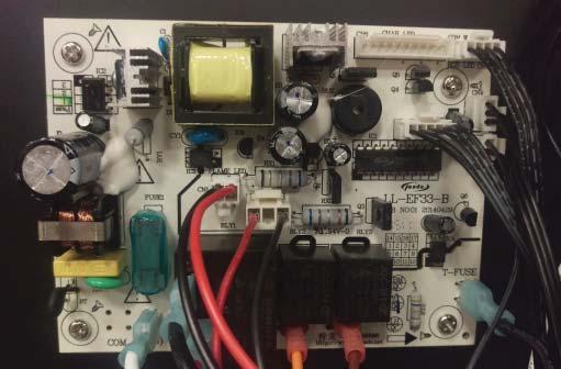
10 3.0 WIRING DIAGRAM CONTROL BOARD DECORATIVE LED MAIN ON/OFF #10 THERMAL CUT OFF #11 #7 #6 #12 HEATER #4 #3 REMOTE RECEIVER TEMPERATURE SENSOR BLOWER AC (N) FAN MOTOR T-FUSE #19 MAIN PCB #9 #1 #5 #13 WIRE NUT FLAME LED WIRE NUT WIRE NUT #14 #17 #16 #18 #2 #15 EMBER BED LED + - MOTOR LOG LED LOG LED PLUG EN 10
11 4.0 TROUBLESHOOTING! WARNING TURN OFF THE APPLIANCE COMPLETELY AND LET THE APPLIANCE COOL DOWN BEFORE SERVICING. IF YOU ARE EXPERIENCING ANY OF THESE ISSUES, UNPLUG APPLIANCE FROM THE POWER OR TURN OFF CIRCUIT BREAKER FOR 30 SECONDS TO FACTORY RESET THE APPLIANCE. FOR ALL HARDWIRED APPLIANCES, DO A VOLTAGE TEST TO ENSURE THAT THERE IS POWER RUNNING THROUGH THE UNIT. SYMPTOM PROBLEM TEST SOLUTION Dim or no flame Dim Flame No moving flame (LED light on) No LED light 1. Press the flame button on the control panel to cycle through brightness levels in order check if the light will get brighter. 2. If light is still dim, refer to section Press the flame button on the control panel to cycle through the flame settings (from F1, F2, F3, to F0) as this could restart the rotisserie to animate the flame. 2. If flame is still not moving, refer to section Press the flame button on the control panel to cycle through the brightness levels 2. If the LED light is still off, refer to section 4.1 Ember bed is not glowing or dimming No warm air is coming out of the appliance LED indicator light is flashing LED flashes 8-10 seconds after pushing heater button Heater shuts off and LED flashes after 30 seconds Heater is on but little to no heat is produced One log has no light/the ember bed light is uneven No light from the ember bed and logs Room temperature is higher than the set temperature setting Appliance has overheated High limit switch is open / has malfunction Blower malfunction One or more heating elements has malfunctioned 1. If the LED strip has one or more LEDs that does not light up, refer to section Press the flame button on the control panel to cycle through the brightness levels as this could restart the ember bed LED strip. 2. If the LED light is still off, refer to section Set temperature to a higher setting with remote control. 2. If heater does not turn on, proceed with "LED indicator light is flashing" test solution. 1. Unplug the appliance and wait minutes for the appliance to cool down 2. Ensure nothing is blocking the air flow from the exhaust of the appliance 3. Plug in the appliance. If problem persists, refer to section Refer to section 4.3 Decorative LEDs are not functioning properply E1 Error Code One or more colours are not visible No LED light Thermostat failure 1. Press the decorative light button on the remote control to set the unit to the d2 setting. Wait for 60 seconds. 2. If any of the colours are not working, refer to section Ensure wire connections are firmly connected at the thermostat and PCB. 2. If appliance is still showing error code E1, replace thermostat. Refer to section 5.8 E2 Error Code Thermostat or PCB is shorting 1. Ensure wire connections are firmly connected at the thermostat and PCB. 2. If unit is still showing error code E2, replace thermostat. Refer to section If unit is still showing error code E2, replace the PCB. Refer to section EN
12 SYMPTOM PROBLEM TEST SOLUTION Abnormal noise coming from the appliance when flame is on Motor / rotisserie issue Obstructing object hitting the rotisserie Loose motor mount Out of spec motor 1. Ensure parts are free from any obstructions and inspect for loose parts. Refer to section 4.1 for further testing. Abnormal noise coming from the blower Obstructing object hitting the blower Unbalanced blower Loose blower mount 1. Inspect and/or replace blower. Dead on arrival Problem with power supply connections Defective PCB 1. Inspect and/or replace connections 1. Inspect PCB / fuse. If damaged/defective, replace parts. EN 12
 Plug in the appliance (if hardwired, turn on circuit breaker)")
 MOTOR Set multimeter to read DC voltage")
 Place negative probe in the CN1- terminal with the black wire (Figure 3) Is the voltage reading within 8V - 12V DC?")
13 4.1 FLAME LED TESTING Appliance is functioning accordingly. Refer to sections for part reinstallation Is the rotisserie turning? Perform motor testing (Section 4.1.2) START HERE Unplug the appliance (if hardwired, turn off circuit breaker) To gain access to the PCB and wire harness, refer to sections Ensure the wires from the flame LED are not pinched, frayed, and are firmly connected on the PCB and flame LED (Figure 1 and 2) Plug in the appliance (if hardwired, turn on circuit breaker) Cycle through the brightness settings by pushing the flame button on the control panel Perform LED testing (Section 4.1.1) Is the rotisserie turning? Perform motor and LED testing (Section ) FIG. 1 Are the LEDs on? FIG. 2 FLAME LED WIRING LED TESTING START HERE FLAME LED TERMINAL Unplug in the appliance (If hardwired, turn off circuit breaker) MOTOR Set multimeter to read DC voltage Plug the appliance (If hardwired, turn on circuit breaker) FIG. 3 Place positive probe in the CN1+ terminal with the red wire (Figure 3) Place negative probe in the CN1- terminal with the black wire (Figure 3) Is the voltage reading within 8V - 12V DC? Replace the flame LED strip. Refer to section 5.7 (LED Replacement) - + Replace the PCB. Refer to section 5.6 (Control Board Replacement) 13 EN
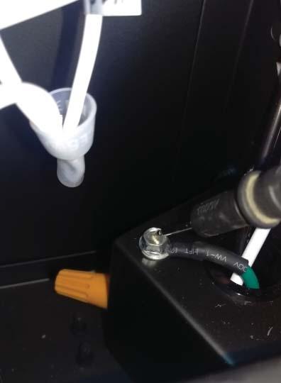
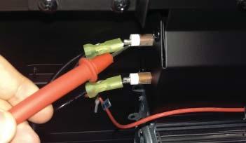
14 4.1.2 MOTOR TESTING START HERE Unplug the appliance (If hardwired, turn off circuit breaker) Set multimeter to read AC voltage Disconnect the wire on the MOTOR terminal on the PCB Place positive probe on the MOTOR terminal (Figure 2) Place negative probe on the ground screw on the junction box located in the bottom right corner of the appliance (Figure 4) Plug in the appliance (If hardwired, turn on circuit breaker) Replace the wire harness Is there a voltage reading approximately 120V AC? Reconnect the wire into the MOTOR terminal on the PCB Follow the wire from the motor until you reach the clear plastic connectors and disconnect them (Figure 5) Using the connector from the PCB/wire harness, place positive probe into the terminal with the brown wire and the negative probe into the terminal with the white wire (Figure 6) Replace the motor. Refer to section 5.5 (Motor Replacement) Is the voltage reading approximately 120V AC? Replace the PCB. Refer to section 5.6 (Control Board Replacement) EN 14


15 FIGURES FIG. 4 - FIG. 5 FIG EN
16 4.2 LOG/EMBER BED LED TESTING START HERE Unplug the appliance (if hardwired, turn off circuit breaker) To gain access to the PCB and wire harness, refer to sections Ensure the wires from log/ember bed LED are not pinched, frayed, and are firmly connected on the PCB and log/ember bed LED (Figure 7) Plug in the appliance (if hardwired, turn on circuit breaker) Cycle through the brightness settings by pushing the flame button on the control panel Are the log/ember LEDs working? Appliance is functioning accordingly. Refer to sections for part reinstallation Turn off appliance (Control panel switch) Set multimeter to read DC voltage Place positive probe in the CN2+ terminal with the red wire (Figure 8) Place negative probe in the CN2- terminal with the black wire (Figure 8) Turn appliance on (Control panel switch) Is the voltage reading within 8V - 12V DC? Replace the PCB. Refer to section 5.6 (Control Board Replacement) TE: THE VOLTAGE READING WILL CONSTANTLY FLUCTUATE Turn off appliance (Control panel switch) Keep positive probe in the CN2+ terminal with the red wire Place the negative probe into the connector with the black wire of the ember bed LED strip (Figure 9) Turn off appliance (Control panel switch) Keep positive probe in the CN2+ terminal with the red wire Place the negative probe into the connector with the black wire of the left log LED (Figure 9) Turn off appliance (Control panel switch) Keep positive probe in the CN2+ terminal with the red wire Place the negative probe into the connector with the black wire of the right log LED (Figure 9) Turn appliance on (Control panel switch) Turn appliance on (Control panel switch) Turn appliance on (Control panel switch) Is the voltage reading within 5V - 7V DC? Is the voltage reading within 7V - 9V DC? Is the voltage reading within 9V - 12V DC? Replace the ember bed LED strip. Refer to section 5.7 (LED Replacement) Replace the left log LED. Refer to section 5.7 (LED Replacement) Replace the right log LED. Refer to section 5.7 (LED Replacement) Turn off appliance (Control panel switch) Perform a continuity test of the wire harness Place positive probe in the CN2- terminal with the black wire and keep the negative probe in the connector with the black wire of the right log LED EN Replace LEDs (Refer to section 5.7) 16 Did it pass the continuity test? Replace the wire harness


17 FIGURES + - LOG/EMBER BED LED TERMINAL FIG. 7 FIG. 8 - FIG EN
18 4.3 HEATER/BLOWER TESTING START HERE Unplug the appliance (if hardwired, turn off circuit breaker) To gain access to the PCB and wire harness, refer to sections Perform a visual check for burns, sparks, damages, etc. Replace any damaged parts Ensure the wires from FAN and HEATER are not pinched, frayed, and are firmly connected on both sides (Figure 10) Perform heater testing (Section 4.3.2) Appliance is fuctioning accordingly. Refer to sections for part reinstallation Is the blower on? Plug in the appliance (if hardwired, turn on circuit breaker) Turn on heater by pressing the heater button on the control panel Is the heater on? Does the appliance turn off after 8 seconds of pressing the heater button? Is the blower on? Perform high limit switch testing (Section 4.5) Perform blower testing (Section 4.3.1) Perform blower and heater testing (Section ) BLOWER TESTING Unplug the appliance (if hardwired, turn off circuit breaker) Check if fan spins with little or no resistance EN START HERE Set multimeter to read AC voltage Disconnect the orange wire on the FAN terminal on the PCB (Figure 10) Place the positive probe on the FAN terminal (Figure 11) Place the negative probe on the ground screw on the junction box (Figure 12) Plug the appliance (if hardwired, turn on circuit breaker) Turn on heater by pressing the heater button on the control panel 18 Is the voltage reading approximately 120V AC? Unplug the appliance (if hardwired, turn off circuit breaker) Follow the wire from the fan until you reach the clear plastic connectors, and disconnect Identify which side of the disconnected wire is coming from the PCB Replace the wire harness PCB needs to be replaced Refer to section 5.6 (Control Board Replacement) Place the positive probe into the terminal with the orange wire (Figure 13) Place the negative probe into the terminal with the white wire (Figure 13) Plug in the appliance (if hardwired, turn on circuit breaker) Turn on heater by pressing the heater button on the control panel Is the voltage reading approximately 120V AC? Replace the blower Refer to section 5.12 (High Limit Switch, Heater, and Blower Replacement)


19 FIGURES HEATER TERMINAL FAN TERMINAL FIG FIG. 11 FIG FIG EN
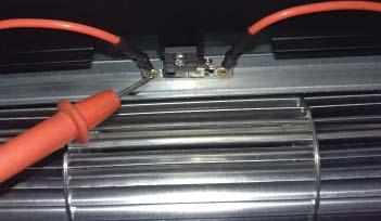
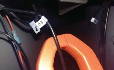
20 4.3.2 HEATER TESTING! WARNING RISK OF ELECTRICAL SHOCK. THIS SECTION REQUIRES THE APPLIANCE AND THE HEATER TO STAY TURNED ON. DO T UNPLUG ANY CONNECTIONS WHILE PERFORMING THE STEPS OF THIS SECTION. START HERE Turn appliance on using the rocker switch Set multimeter to read AC voltage Place the positive probe on the rear left terminal of the heating element (Figure 19) Place the negative probe on the AC-N terminal on the PCB (Figure 14) Is the voltage reading approximately 120V AC? Replace wire harness Ensure power supply connections are in. Refer to section 3.0 (Wiring Diagram) Place the positive probe on the COMM terminal on the largest relay of the PCB (Figure 15) Is the voltage reading approximately 120V AC? Place the positive probe on the N.O. terminal on the largest relay of the PCB (Figure 16) Place the positive probe on the front left terminal of the heating element (Figure 20) Is the voltage reading approximately 120V AC? Remove the negative probe on the AC-N terminal and place it on the right terminal of the heating element Replace wire harness Replace PCB. Refer to section 5.6 (Control Board Replacement) Press the heater button and wait 8 seconds Is the voltage reading approximately 120V AC? Is the voltage reading approximately 120V AC? Replace the heater. Refer to section 5.12 (High Limit Switch, Heater, and Blower Replacement) Replace high limit switch. Refer to section 5.12 (High Limit Switch, Heater, and Blower Replacement) Place the positive probe on the right terminal of the high limit switch (Figure 17) Is the voltage reading approximately 120V AC? Set a clamp multimeter to read amperage and clamp around wire #3 (Figure 21) Is the amperage reading approximately 10A? Replace the heater. Refer to section 5.12 (High Limit Switch, Heater, and Blower Replacement) Place the postive probe on the left terminal of the high limit switch (Figure 18) Replace wire #3 on the right side of the heater Replace wire harness EN 20 Is the voltage reading approximately 120V AC?


21 FIGURES + - FIG. 14 FIG FIG. 16 FIG FIG. 18 FIG FIG. 20 FIG EN
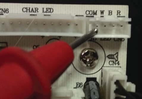
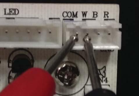
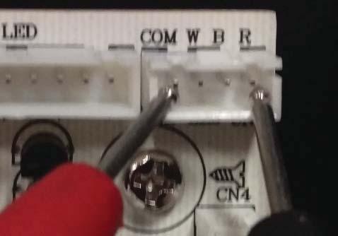
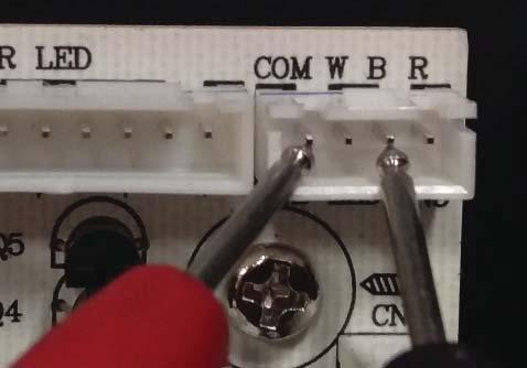
22 4.4 DECORATIVE LED TESTING! WARNING DO T LET PROBES TOUCH WHILE TESTING CN5 TERMINAL ON THE PCB. THIS WILL SHORT THE ENTIRE APPLIANCE. START HERE Unplug the appliance (if hardwired, turn off circuit breaker) Turn appliance off (control panel switch) To gain access to the PCB, wire harness, and decorative LED, refer to sections and 5.11 (Step B) Unplug the connector from CN5 Ensure the wires from decorative LED (CN5) are not pinched, frayed, and are firmly connected on the PCB and decorative LED (Figure 22) Turn appliance on (control panel switch) Set multimeter to read DC voltage and appliance to the d2 setting Plug in the appliance (if hardwired, turn on circuit breaker) Set the appliance to d2 setting by pressing the decorative light button on the remote control Place the positive probe on the CN5 COMM connector pin (Figure 23) Place the negative probe on the the CN5 W connector pin (Figure 24) Wait 60 seconds and observe the d2 colour cycle (Decorative Light Settings) Are all colours working? (blue, white, and yellow) Wait 60 seconds Place the negative probe on the the CN5 R connector pin (Figure 25) Wait 60 seconds Place the negative probe on the the CN5 B connector pin (Figure 26) Appliance is functioning accordingly. Refer to section for part reinstallation Replace the decorative LED strip. Refer to section 5.7 (LED replacement) Wait 60 seconds Is the voltage reading 12V DC for each connector pins? DECORATIVE LIGHT SETTINGS There are three settings to cycle through and an off setting (d1, d2, d3 and then d0). The d1 setting turns the light to white. The d2 setting cycles the decorative LED in the following order: - White to orange - Orange to blue - Blue to orange & blue - Orange & blue to orange & white - Orange & white to white & blue Replace the PCB. Refer to section 5.6 (Control Board Replacement) It will take 8.5 seconds to switch from one colour to the next when in d2 setting. The d3 setting will lock to a desired colour from the d2 setting. EN 22
23 FIGURES DECORATIVE LED TERMINAL FIG FIG. 23 FIG FIG. 25 FIG EN
24 4.5 HIGH LIMIT SWITCH TESTING START HERE Unplug the appliance (if hardwired, turn off circuit breaker) Leave appliance turned off for minutes for the appliance to cool down Inspect wires to and from the high limit switch to ensure there are no damaged or disconnected wires If the appliance is shutting off constantly 8-10 sec after heater button is pushed. The high limit switch and/or circuit is open Inspect wires # 9, 10, 11, 12, 13, and 19. Refer to the wiring diagram Ensure there are no frayed or damaged wires Are there any broken connectors or wires? Replace broken connectors or wires TE: THIS ENSURES THE HIGH LIMIT SWITCH HAS COOLED DOWN AND RESET Unplug # 19 wire from PCB to the T-fuse connector Measure continuity from N.O. terminal on the biggest relay of the PCB Is there continuity? Check continuity from N.O. terminal to the right terminal of the high limit switch Is there continuity? Check continuity from the N.O. terminal to the left terminal of the high limit switch Is there continuity? Check continuity from he N.O. terminal to the left heater terminals Replace the PCB. Refer to section 5.6 (Control Board Replacement) Replace the high limit switch. Refer to section 5.12 (High Limit Switch, Heater, and Blower Replacement) Replace the high limit switch. Refer to section 5.12 (High Limit Switch, Heater, and Blower Replacement) Replace the high limit switch wire Is there continuity? Replace the PCB. Refer to section 5.6 (Control Board Replacement) EN 24
25 5.0 MAINTENANCE! WARNING ALWAYS DISCONNECT THE POWER AND ALLOW THE ELECTRIC APPLIANCE TO COOL BEFORE PERFORMING ANY CLEANING, MAINTENANCE, OR RELOCATION OF THIS ELECTRIC APPLIANCE. TURN CONTROLS TO OFF AND REMOVE PLUG FROM OUTLET OR TURN OFF THE HOUSE CIRCUIT BREAKER TO ELECTRIC APPLIANCE RECEPTACLE. DO T INSTALL REPLACEMENT LED LIGHTS THAT EXCEED SPECIFIED MAXIMUM WATTS.! TE: Only a qualified service technician or service agency should service this electric appliance. 5.1 GLASS DOOR REMOVAL AND INSTALLATION! WARNING THE DOOR LATCHES ARE PART OF A SAFETY SYSTEM AND MUST BE PROPERLY ENGAGED. DO T OPERATE THE APPLIANCE WITH LATCHES DISENGAGED. FACING AND/OR FINISHING MATERIALS MUST T INTERFERE WITH AIR FLOW THROUGH AIR OPENINGS, LOUVRE OPENINGS, OPERATION OF LOUVRES OR DOORS OR ACCESS FOR SERVICE. OBSERVE ALL CLEARANCES WHEN APPLYING COMBUSTIBLE MATERIALS. BEFORE DOOR IS REMOVED TURN THE APPLIANCE OFF AND WAIT UNTIL APPLIANCE IS COOL TO THE TOUCH. DOORS ARE HEAVY AND FRAGILE SO HANDLE WITH CARE A. To remove the glass door, swing the top two latches to release the door. The door will hang slightly on the safety catch wire. TE: Pushing in the door, will make the latch swing easier. B. Place one hand on the glass door while removing the screw from the catch wire. Allow the door to pivot slightly, hold the sides with both hands while lifting the door out of the appliance. C. To install the glass door, simply place the door on the holding pins on the bottom frame of the appliance. Install the screw into the safety catch wire, slightly push the glass door into the frame and latch it secure with the two top latches. LATCH OPEN LOCK SAFETY CATCH WIRE SCREW * ILLUSTRATED WITH LATCHES VISIBLE 25 EN
26 5.2 LOG, GRATE AND EMBER BED ASSEMBLY REMOVAL A. Remove the card board holding the logs, grate and ember bed assembly to the appliance. B. Pinch the back of the assembly and lift it up from the appliance. GRATE EMBER BED * ILLUSTRATED WITH LOGS T SHOWN EN 26
27 5.3 FLAME GLASS REMOVAL A. Place a hand on the glass to hold it in place while removing the 10 screws on the bottom of the glass. The glass will fall down to 2 holding tabs. B. Tilt the glass forward on the bottom with both hands, lift the glass up and out of the appliance. C. Place the glass on a soft, non-abrasive surface. TE: The flame glass is made out of tempered glass. HOLDING TABS LOG LED INSTRUCTIONAL VIDEO: HOW TO REMOVE FLAME GLASS 5.4 FLAME BOARD REMOVAL A. Remove the 5 screws on the bottom and 4 screws on top of the flame board. B. Lift the flame board out of the appliance. INSTRUCTIONAL VIDEO: HOW TO REMOVE FLAME BOARD 27 EN


28 5.5 MOTOR REPLACEMENT A. To gain access to the motor, see sections B. To remove the reflector, pull the reflector away from the motor for it to release. C. Remove the rubber adaptor from the motor. D. Unplug the quick connect motor wire from the wire harness. E. Unscrew the 2 screws holding the motor and take the motor out of the appliance. F. Install the new motor. G. Reinstall the screws, rubber adaptor, and reflector. REFLECTOR ADAPTOR MOTOR INSTRUCTIONAL VIDEO: HOW TO REPLACE MOTOR 5.6 CONTROL BOARD REPLACEMENT A. To gain access to the PCB, see sections B. Unplug all the wires connected to the control board. TE: For ease of wire disconnection, use a pair of needle-nose pliers. C. Remove control board from appliance. TE: To prevent stripping of the plastic plugs on the back of the control board, hold the plugs with pliers while removing each of the 4 screws. D. Screw the new board into the plugs in the same orientation as before. E. Connect all of the wires to the board. See 5.8 figure 1 for reference. INSTRUCTIONAL VIDEO: HOW TO REPLACE CONTROL BOARD EN 28

29 5.7 LED REPLACEMENT A. Find the connector on the PCB for the LED you want to replace and unplug it (Section 5.8 Figure 1). B. Cut the cable tie. C. Unscrew the LED strip from the appliance. If unscrewing the log LEDs, use a pair of needle nose pliers to hold the plastic plugs in place. D. Screw in the new LED strip onto the appliance and connect the wires to the designated quick connect plugs. E. Using a cable tie, secure the wires. 5.8 REMOTE RECEIVER / THERMOSTAT REPLACEMENT A. To gain access to the remote receiver or thermostat, see sections and 5.11 (Step B). B. Find the connector on the PCB for the component you want to replace and uplug it (Figure 1). C. Cut the cable tie. D. Unscrew the component from the appliance. E. Screw the new component and connect the wires to the designated quick connect plugs. F. Using a cable tie, secure the wires. FIG. 1 DECORATIVE LED REMOTE RECEIVER THERMOSTAT CONTROL PANEL FLAME LED EMBER BED / LOG LED 29 EN


30 5.9 FUSE REPLACEMENT A. To gain access to the fuse on the PCB refer to sections B. Remove the plastic cover from the fuse. C. Pull the fuse (2Amp) out from the control board. D. Install the replacement fuse and plastic cover. FUSE COVER 5.10 REMOTE BATTERY REPLACEMENT A. Turn over the remote with rear side facing up. Slide the battery cover off the remote. B. Remove old battery and replace the type CR 2032 battery into the remote and reinstall the battery cover by sliding it into position, as shown. TE: For ease of installation, hold the batter while sliding the cover onto the remote. C. Battery cover is secure onto the remote control when a "CLICKING" noise is heard. REMOTE (REAR SIDE) BATTERY (CR 2032) BATTERY COVER EN 30

31 5.11 CONTROL PANEL REPLACEMENT A. Disconnect the control panel remote receiver and decorative LED, quick connect plugs from the printed control board (PCB). B. Place one hand on the top rear panel and remove the 4 screws. Repeat the same process to remove the 5 screws for the top front panel. C. Unscrew the 3 middle screws holding the control panel bracket on the front edge of the appliance, remove the control panel bracket from the appliance (Figure 2). D. Remove the 2 screws holding the control panel to the bracket. E. Replace the new control panel, plug control panel, remote receiver and decorative LED to the control board. FIG. 1 CONTROL PANEL DECORATIVE LED LIGHT PANELS CONTROL PANEL LED CONNECTOR PCB FIG. 2 INSTRUCTIONAL VIDEO: HOW TO REPLACE CONTROL PANEL 31 EN
32 5.12 HIGH LIMIT SWITCH, HEATER, AND BLOWER REPLACEMENT A. Remove the top front and top rear panels. Refer to section 5.11 (Step B). B. Unplug the wires connected to the heater and blower. TE: Use pliers to pinch the connector free from the heater tabs for easier removal. C. Remove the 6 screws that secure the heater and blower assembly to the appliance (Figure 1). D. Take the blower and heater assembly out of the appliance. E. Remove the 6 screws that secure the blower to the bracket (Figure 2). F. Remove the 3 screws located on the sides of the heater housing then remove the heater by sliding it up and out of the housing (Figure 3). G. Remove the wires by removing the single screw from the back of the heater housing, then bend the two tabs upwards that secure the wires in place (Figure 4). FIG. 1 FIG. 2 FIG. 3 FIG. 4 INSTRUCTIONAL VIDEO: HOW TO REPLACE HIGH LIMIT SWITCH, HEATER, AND BLOWER EN 32
33 6.0 TES EN


34 Products Other Napoleon napoleonproducts.com
INSTALLATION AND OPERATION INSTRUCTIONS FOR WALL-MOUNT AND BUILT-IN UNITS
 INSTALLATION AND OPERATION INSTRUCTIONS FOR WALL-MOUNT AND BUILT-IN UNITS WM-FM-50-BG SAFETY INFORMATION WARNING If the information in these instructions are not followed exactly, a fire or explosion may
INSTALLATION AND OPERATION INSTRUCTIONS FOR WALL-MOUNT AND BUILT-IN UNITS
 INSTALLATION AND OPERATION INSTRUCTIONS FOR WALL-MOUNT AND BUILT-IN UNITS WM-FML-26-3223-STL WM-FML-34-4023-STL WM-FML-48-5523-STL WM-FML-60-6623-STL WM-FML-72-7823-STL WM-FML-88-9623-STL SAFETY INFORMATION
INSTALLATION AND OPERATION INSTRUCTIONS FOR BI-DEEP UNITS
 INSTALLATION AND OPERATION INSTRUCTIONS FOR BI-DEEP UNITS BI-40-DEEP BI-50-DEEP BI-60-DEEP BI-72-DEEP BI-88-DEEP SAFETY INFORMATION WARNING If the information in these instructions are not followed exactly,
MILLA ELECTRIC FIREPLACE
 MILLA ELECTRIC FIREPLACE MODEL NO. 064-3177-0 ASSEMBLY INSTRUCTIONS Toll-free: 1-888-670-6684 IMPORTANT: Please read this manual carefully before beginning assembly of this product. Keep this manual for
INSTALLATION AND OPERATION INSTRUCTIONS FOR
 INSTALLATION AND OPERATION INSTRUCTIONS FOR BI-40-DEEP-XT BI-50-DEEP-XT BI-60-DEEP-XT BI-72-DEEP-XT BI-88-DEEP-XT SAFETY INFORMATION WARNING If the information in these instructions are not followed exactly,
Service Manual. Model Number: DFR2651L. UL Part Number
 Service Manual Model Number: DFR2651L UL Part Number 6908932259 IMPORTANT SAFETY INFORMATION: Always read this manual first before attempting to service this fireplace. For your safety, always comply with
INSTALLATION AND OPERATION INSTRUCTIONS FOR ZERO CLEARANCE AND INSERT UNITS
 INSTALLATION AND OPERATION INSTRUCTIONS FOR ZERO CLEARANCE AND INSERT UNITS ZECL-26-2923-BG ZECL-30-3226-BG ZECL-33-3624-BG ZECL-39-4134-BG ZECL-2939-BG INSERT-26-3825-BG INSERT-30-4026-BG INSERT-33-4230-BG
INSTALLATION AND OPERATION INSTRUCTIONS FOR SAFETY INFORMATION WARNING
 INSTALLATION AND OPERATION INSTRUCTIONS FOR 102735-XS 102745-XS 102755-XS 102765-XS SAFETY INFORMATION WARNING If the information in these instructions are not followed exactly, a fire or explosion may
Service Manual. Model Number: DF2024. UL Part Number
 Service Manual Model Number: DF2024 UL Part Number 6908891459 6908891559 IMPORTANT SAFETY INFORMATION: Always read this manual first before attempting to service this fireplace. For your safety, always
PARTS & SERVICE MANUAL
 MODEL BF6000 PARTS & SERVICE MANUAL Formally Sold under 7400460100R00 Table of Contents OPERATION... 3 WIRING DIAGRAM... 6 REPLACEMENT PARTS... 6 TO REPLACE UPPER LIGHT BULBS... 7 TO REPLACE LOWER LIGHT
BF5000NT BF5000 EF2604 SF2603 DF2603
 PARTS & SERVICE MANUAL FOR THE 26 FIREPLACE MODEL NUMBER: BF5000NT BF5000 EF2604 SF2603 DF2603 7400520000R03 TABLE OF CONTENTS Table of Contents OPERATION... 2 EXPLODED DIAGRAM... 4 WIRING DIAGRAM... 5
HD81 GLASS BURNER ASSEMBLY
 INSTALLER: LEAVE THIS MANUAL WITH THE APPLIANCE. CONSUMER: RETAIN THIS MANUAL FOR FUTURE REFERENCE. 1 INSTALLATION AND OPERATING INSTRUCTIONS CERTIFIED UNDER CANADIAN AND AMERICAN NATIONAL STANDARDS: CSA
Service Manual. Model UL Part Number XLF XLF XLF
 Service Manual Model UL Part Number XLF50 6909630100 XLF74 6909690100 XLF100 6909700100 IMPORTANT SAFETY INFORMATION: Always read this manual first before attempting to service this fireplace. For your
Service Manual. Model Number: Compact Fireplace DF203A DF2006. UL Part Number to 800
 Service Manual Model Number: Compact Fireplace DF203A DF2006 UL Part Number 6901860100 to 800 IMPORTANT SAFETY INFORMATION: Always read this manual first before attempting to service this fireplace. For
PARTS AND SERVICE MANUAL FOR. DIMPLEX PURIFIRE ELECTRIC STOVE Model TDS8515
 PARTS AND SERVICE MANUAL FOR DIMPLEX PURIFIRE ELECTRIC STOVE Model TDS8515 7400050000R04 Table of Contents OPERATION... 2 WIRING DIAGRAM... 5 REPLACEMENT PARTS... 7 UPPER LIGHT BULB REPLACEMENT... 8 LOWER
Service Manual. Model Number: DF2524L DF2524G. UL Part Number
 Service Manual Model Number: DF2524L DF2524G UL Part Number 6908921359 6908921459 IMPORTANT SAFETY INFORMATION: Always read this manual first before attempting to service this fireplace. For your safety,
Service Manual. Model Number: DF2624L. UL Part Number
 Service Manual Model Number: DF2624L UL Part Number 6908931359 IMPORTANT SAFETY INFORMATION: Always read this manual first before attempting to service this fireplace. For your safety, always comply with
IMPORTANT SAFETY INFORMATION
 Service Manual Model BSL33 UL Part Number 6905280100 IMPORTANT SAETY INORMATION: Always read this manual first before attempting to service this fireplace. or your safety, always comply with all warnings
SAVE THESE INSTRUCTIONS
 Fireplace User Guide MODEL#: EF16-60 SAVE THESE INSTRUCTIONS THIS PRODUCT WAS MANUFACTURED BY PAITE FOR ASHLEY FURNITURE INDUSTRIES, INC. All Rights Reserved. Page 1 of 15 Table Of Contents Table of Contents...2
Service Manual. Model RLG20 RLG25. Part Number
 Service Manual Model RLG20 RLG25 Part Number 6909740159 6909760159 IMPORTANT SAFETY INFORMATION: Always read this manual first before attempting to service this log grate. For your safety, always comply
Gallery Electric Fireplaces
 Gallery Electric Fireplaces Homeowner s Installation Instructions & Operating Manual Model: GE-50, GE-58, GE-70, GE-78 GE-94 FOR YOUR SAFETY SERVICE MUST BE PERFORMED BY A QUALIFIED SERVICE AGENCY. DO
IMPORTANT SAFETY INFORMATION! WARNING ALWAYS keep electric cords, home furnishings, drapes, clothing, papers, or other combustibles at least 3 feet (0
 Electric Fireplace Factory Model: EF-30D CONSUMER SAFETY INFORMATION Read this manual before installing and operating this appliance Failure to follow these instructions may result in electric shock, fire
23-IN Electric Logset
 23-IN Electric Logset ASSEMBLY, CARE & USE INSTRUCTIONS MODEL # ELCG240-INF Questions, problems, missing parts? Before returning to your retailer, call our customer service department at 1-855-571-1044
IMPORTANT SAFETY INFORMATION
 Service Manual Model Number DS5629 UL Part Number 6900471359 IMPORTANT SAFETY INFORMATION: Always read this manual first before attempting to service this stove. For your safety, always comply with all
IMPORTANT SAFETY INFORMATION
 Service Manual Model Number: PF2325 PF3033 UL Part Number 690932XXXX IMPORTANT SAFETY INFORMATION: Always read this manual first before attempting to service this fireplace. For your safety, always comply
IMPORTANT SAFETY INFORMATION
 Service Manual Model Number: DF2600 UL Part Number 690893XXXX IMPORTANT SAFETY INFORMATION: Always read this manual first before attempting to service this fireplace. For your safety, always comply with
Service Manual 26 Self Trimming Export Fireplace with 3 Stage On/Off Remote
 Service Manual 26 Self Trimming Export Fireplace with 3 Stage On/Off Remote Model Numbers: DF2608-EU - MOD / to A DF2608-AU - MOD / Dimplex North America Limited 1367 Industrial Road Cambridge ON Canada
IMPORTANT SAFETY INFORMATION
 Service Manual Model Number: DF2000 UL Part Number 690889XXXX IMPORTANT SAFETY INFORMATION: Always read this manual first before attempting to service this fireplace. For your safety, always comply with
Summer Breeze Heater Service Manual
 Summer Breeze Heater Service Manual RSBH RSBH-SB RSBHP Revision: 1.0 Issued: 12-18-2012 Table of Contents I. Basic Assembly and Operation A. Safety Instructions... 2 B. Grounding Instructions... 3 C.
Service Manual 23 Compact Fireplace Model Number: DF2305
 DF2305 & DF2307SS Service Manual 23 Compact Fireplace Model Number: DF2305 DF2307SS DFB4047 DFB2306 DFS2308 DFB2306 & DFS2308 UL Part Number 6901740000 DFB4047 IMPORTANT SAFETY INFORMATION: Always read
ELECTRIC FIREPLACE HEATER MODEL EF-BLT09 OWNER S MANUAL
 ELECTRIC FIREPLACE HEATER MODEL EF-BLT09 OWNER S MANUAL NO VENTILATION REQUIRED PRODUCES SAFE AND EFFICIENT HEAT 110/120-VOLT 60Hz LED BULBS SAVE THESE INSTRUCTIONS FOR FUTURE USE 1 CONSUMER SARETY INSTRUCTIONS
EF5528RKD Freestanding Electric Fireplace
 EF5528RKD Freestanding Electric Fireplace Installation Instructions and Homeowner's Manual WARNING! IF THE INFORMATION IN THIS MANUAL IS NOT FOLLOWED EXACTLY, A FIRE MAY RESULT CAUSING PROPERTY DAMAGE,
Service Manual 26 Self Trimming Fireplace Model Number: DF2608 DF2622 NBDF2608
 Service Manual 26 Self Trimming Fireplace Model Number: DF2608 DF2622 NBDF2608 UL Part Number 6904400359 IMPORTANT SAFETY INFORMATION: Always read this manual first before attempting to service this fireplace.
Service Manual 26 Self Trimming Fireplace with 3 Stage Remote
 Service Manual 26 Self Trimming Fireplace with 3 Stage Remote Model Number: DF2690 MOD: 0 Dimplex North America Limited 1367 Industrial Road Cambridge ON Canada N1R 7G8 1-800-668-6663 www.dimplex.com REV
Gallery Electric Fireplaces
 Gallery Electric Fireplaces Homeowner s Installation Instructions & Operating Manual Model: GBL-44 FOR YOUR SAFETY SERVICE MUST BE PERFORMED BY A QUALIFIED SERVICE AGENCY. DO NOT STORE OR USE GASOLINE
Service Manual. Model Number VCX1525 VCX1525-WH. UL Part Number
 Service Manual Model Number VCX1525 VCX1525-WH UL Part Number 6904000100 IMPORTANT SAFETY INFORMATION: Always read this manual first before attempting to service this fireplace. For your safety, always
INSTALLATION AND OPERATING INSTRUCTIONS
 INSTALLER: LEAVE THIS MANUAL WITH THE APPLIANCE. CONSUMER: RETAIN THIS MANUAL FOR FUTURE REFERCE. NEVER LEAVE CHILDR OR OTHER AT RISK INDIVIDUALS ALONE WITH THE APPLIANCE. INSTALLATION AND OPERATING INSTRUCTIONS
Service Manual 26 Self Trimming Fireplace Model Number: DF2608 DF2622 NBDF2608
 Service Manual 26 Self Trimming Fireplace Model Number: DF2608 DF2622 NBDF2608 IMPORTANT SAFETY INFORMATION: Always read this manual first before attempting to service this fireplace. For your safety,
CERTIFIED UNDER CANADIAN AND AMERICAN NATIONAL STANDARDS: CSA C22.2 No-46 / UL 2021 NEFE AM-1 ELECTRIC FIREPLACE MANTEL
 INSTALLER: LEAVE THIS MANUAL WITH THE APPLIANCE. CONSUMER: RETAIN THIS MANUAL FOR FUTURE REFERCE. NEVER LEAVE CHILDR OR OTHER AT RISK INDIVIDUALS ALONE WITH THE APPLIANCE. INSTALLATION AND OPERATING INSTRUCTIONS
 Electric Fireplace Instruction Manual MODELS : 18EF023GRA, 18EF023SRA, 23EF023GRA, 23EF023SRA, 25EF023GRA, 26EF023GRA, 26EF023SRA, 28EF023GRA, 28EF023SRA, 32EF023GRA, 32EF023SRA, 33EF023GRA, 33EF023SRA
40 Built-in Electric Fireplace Operating and Installation Instructions
 40 Built-in Electric Fireplace Operating and Installation Instructions This manual is for use with Furrion FF40S15A-BL 40 Built-in Electric Fireplace 1 Welcome Furrion FF40S15A-BL 40 Built-in Electric
Installation and Operation Instructions ELECTRIC FIREPLACE X30WMEF1BLK X30WMEF1WHT
 Installation and Operation Instructions ELECTRIC FIREPLACE X30WMEF1BLK X30WMEF1WHT 1 Important Safety Instructions Listing Approvals Product Dimensions Locating Fireplace Unpacking and Testing Fireplace
Installation and Operation Instructions ELECTRIC FIREPLACE X56WMEF1BLK X56WMEF1WHT
 Installation and Operation Instructions ELECTRIC FIREPLACE X56WMEF1BLK X56WMEF1WHT Tool list Assembly Instructions Important Safety Instructions Listing Approvals Glass Particles Installation Instructions
ELECTRIC FIREPLACE OWNER S MANUAL
 ELECTRIC FIREPLACE OWNER S MANUAL MODELS EL1346C 4001358 WARNING: If the information in this manual is not followed exactly, a fire or electrical shock may result causing property damage, personal injury
INSTALLER: LEAVE THIS MANUAL WITH THE APPLIANCE. CONSUMER: RETAIN THIS MANUAL FOR FUTURE REFERENCE.
 INSTALLATION AND OPERATION INSTRUCTIONS FOR VISTA-BI-12 UNITS VISTA-BI-50-12 VISTA-BI-60-12 VISTA-BI-72-12 SAFETY INFORMATION WARNING If the information in these instructions are not followed exactly,
HARLOW ELECTRIC FIREPLACE
 HRLOW ELECTRIC FIREPLCE MODEL NO. 064-3504-2 SSEMBLY INSTRUCTIONS Toll-free: 1-888-670-6684 IMPORTNT: Please read this manual carefully before beginning assembly of this product. Keep this manual for future
EF5802R Freestanding Electric Fireplace
 EF5802R Freestanding Electric Fireplace Installation Instructions and Homeowner's Manual WARNING! IF THE INFORMATION IN THIS MANUAL IS NOT FOLLOWED EXACTLY, A FIRE MAY RESULT CAUSING PROPERTY DAMAGE, PERSONAL
ELECTRIC FLAT PANEL FIREPLACE HEATER
 ELECTRIC FLAT PANEL FIREPLACE HEATER Model Numbers: 80-2000A-42 OWNER S MANUAL AC 120V 60Hz 1500W WARNING Read and understand this entire owner s manual, including all safety information, before plugging
EFL32H, EFC32H EFL48H, EFL60H, EFL72H
 INSTALLER: LEAVE THIS MANUAL WITH THE APPLIANCE. CONSUMER: RETAIN THIS MANUAL FOR FUTURE REFERCE. NEVER LEAVE CHILDR OR OTHER AT RISK INDIVIDUALS ALONE WITH THE APPLIANCE. INSTALLATION AND OPERATING INSTRUCTIONS
WALL MOUNT ELECTRIC FIREPLACE OWNERS MANUAL
 WALL MOUNT ELECTRIC FIREPLACE EF-BLT13-36 EF-BLT13-42 EF-BLT13-50 EF-BLT13-60 OWNERS MANUAL NO VENTILATION REQUIRED PRODUCES SAFE AND EFFICIENT HEAT PLEASE READ THIS ENTIRE MANUAL BEFORE USING UNIT 120-VOLT
GARAGE HEATER WITH REMOTE INSTRUCTION MANUAL MODEL: HA24-100E HA24-150E. Figure 1
 GARAGE HEATER WITH REMOTE INSTRUCTION MANUAL MODEL: HA24-100E HA24-150E Figure 1 PET OWNERS WARNING: Health warning for some small pets, including birds, as they are extremely sensitive to the fumes produced
Homeowner s Installation Instructions & Operating Manual
 Homeowner s Installation Instructions & Operating Manual ELECTRIC HEATER WITH REMOTE CONTROL Model: GI-32-ZC IS-36-ZC, IS-42-ZC Insert surrounds READ AND SAVE THESE INSTRUCTIONS READ CAREFULLY BEFORE ATTEMPTING
COMBINATION ELECTRIC FIREPLACE/HEATER Model #FP23-1A-AKM
 LOT NUMBER: DATE PURCHASED: / / USE AND CARE GUIDE COMBINATION ELECTRIC FIREPLACE/HEATER Model #FP23-1A-AKM If you have any questions regarding the use of this unit, or find that your fireplace/heater
ELECTRIC FIREPLACE INSERT MODEL EF-BLT10 OWNER S MANUAL
 ELECTRIC FIREPLACE INSERT MODEL EF-BLT10 OWNER S MANUAL NO VENTING REQUIRED PRODUCES SAFE EFFICIENT HEAT 110-120-VOLT / 1500-WATT READ ENTIRE MANUAL BEFORE USING SAVE THIS MANUAL FOR FUTURE USE 1 SAFETY
ITEM NO. FA532300TX ELECTRIC FIREBOX INSERT OPERATION MANUAL
 ITEM NO. FA532300TX ELECTRIC FIREBOX INSERT OPERATION MANUAL For assistance with assembly, contact: Southern Enterprises Inc. Customer Service 1-800-633-5096 service@seidal.com www.seidal.com Electric
Gallery Electric Fireplaces
 Gallery Electric Fireplaces Homeowner s Installation Instructions & Operating Manual Model: GBI-34, GBI-41 Only use this heater as described in this manual. Any other use is not recommended by the manufacturer,
PARTS AND SERVICE MANUAL FOR THE 23 COMPACT FIREPLACE
 PARTS AND SERVICE MANUAL FOR THE 23 COMPACT FIREPLACE TABLE OF CONTENTS OPERATION PAGE 1 PARTS DRAWING PAGE 3 PARTS LIST PAGE 4 LIGHT BULB REPLACEMENT PAGE 5 HEATER ON/OFF SWITCH REPLACEMENT PAGE 6 THERMOSTAT
Homeowner s Installation Instructions & Operating Manual
 Wall Mounted Electric Fireplace Homeowner s Installation Instructions & Operating Manual Model: EF67B Series Used With Listed Front Facia Only: MT67C01 Black flat glass MT67C02 Black curved glass FOR YOUR
Homeowner s Installation Instructions & Operating Manual
 Wall Mounted Electric Fireplace Homeowner s Installation Instructions & Operating Manual Model: EF68-72 Series Used With Listed Front Facia Only: MT68-72 FOR YOUR SAFETY SERVICE MUST BE PERFORMED BY A
Service Manual. Model Number: DF2426 DF2550 DFG2562 BF9000. UL Part Number to
 Service Manual Model Number: DF2426 DF2550 DFG2562 BF9000 UL Part Number 6905050100 to 500 6907560100 IMPORTANT SAFETY INFORMATION: Always read this manual first before attempting to service this fireplace.
Thanks for shopping with Improvements! Springfield Compact Electric Fireplace Item #470279
 Thanks for shopping with Improvements! Springfield Compact Electric Fireplace Item #470279 To order, call 1-800-642-2112 West Chester, OH 45069 0114 If you have questions regarding this product, call 1-800-642-2112
Service Manual. Model Number: DF2426 DF2550 DFG2562 BF9000. UL Part Number to
 Service Manual Model Number: DF2426 DF2550 DFG2562 BF9000 UL Part Number 6905050100 to 500 6907560100 IMPORTANT SAFETY INFORMATION: Always read this manual first before attempting to service this fireplace.
Service Manual. Model Number: DF2426 DF2550 DFG2562 BF9000. UL Part Number to
 Service Manual Model Number: DF2426 DF2550 DFG2562 BF9000 UL Part Number 6905050100 to 500 6907560100 IMPORTANT SAFETY INFORMATION: Always read this manual first before attempting to service this fireplace.
IMPORTANT SAFETY INFORMATION:
 Owner s Manual Revillusion Built-in Electric Firebox Revillusion 30" Firebox (RBF30-AU) Revillusion 36" Firebox (RBF36-AU) Revillusion 36" Firebox P (RBF36P-AU) Revillusion 42" Firebox (RBF42-AU) IMPORTANT
Service Manual. Model Number VCX1525 VCX1525-WH. UL Part Number
 Service Manual Model Number VCX1525 VCX1525-WH UL Part Number 6904000100 IMPORTANT SAFETY INFORMATION: Always read this manual first before attempting to service this fireplace. For your safety, always
INSTALLATION INSTRUCTIONS
 CERTIFIED INSTALLER: LEAVE THESE INSTRUCTIONS WITH THE APPLIANCE THIS TERMINAL IS SERVING. CONSUMER: RETAIN THESE INSTRUCTIONS FOR FUTURE REFERENCE. THESE INSTRUCTIONS ARE TO BE USED IN CONJUNCTION WITH
Please Keep This Manual For Future Reference REV.01
 CS-25IR-BLK CS-25IR-CRM CS-25IR-BRZ CS-25IR-GM 1-855-571-1044 Please Keep This Manual For Future Reference REV.01 M PACKAGE CONTENTS A C B PART DESCRIPTION QUANTITY A Body 1 B Leg 4 C Remote Control 1
Scan the below QR code to download Smart Flame
 bc Scan the below QR code to download Smart Flame. 1-855-837-2569 licensed fire, electric shock or injury to persons. tap (outlet/power strip). 19.The heater has a safety device that makes it stop working
ELECTRIC FIREPLACE MODEL NO. OL-L6G
 Installation Instructions and Homeowner, s Manual INSTALLER: DO NOT DISCARD THIS MANUAL - LEAVE FOR HOMEOWNER ELECTRIC FIREPLACE MODEL NO. OL-L6G WARNING! IF INFORMATION IN THIS MANUAL IS NOT FOLLOWED
Service Manual. Model Number: BF362SD BF392SD. UL Part Number
 Service Manual Model umber: BF362SD BF392SD UL Part umber 6901550159 IMPORTAT SAFETY IFORMATIO: Always read this manual first before attempting to service this fireplace. For your safety, always comply
W / C / W / C /
 1 2 TABLE of CONTENTS PG 2-4 INTRODUCTION Warranty Important Instructions Locating Your Fireplace Dimensions 5 OPERATION Flame Effect Maintenance 5-7 FINISHING Mantel Installation Clearance to Combustibles
Installation Instructions & Operating Manual IMPORTANT
 Installation Instructions & Operating Manual IMPORTANT These instructions should be read carefully and retained for future reference TABLE OF CONTENTS SECTION 1: WARNINGS & ELECTRIC SPECIFICATIONS 1.1
ELECTRIC FLAT PANEL FIREPLACE HEATER. Model# : BG-36B BG-45B BG-50B BG-60B BG-72B BG-100B OWNER S MANUAL
 ELECTRIC FLAT PANEL FIREPLACE HEATER Model# : BG-36B BG-45B BG-50B BG-60B BG-72B BG-100B OWNER S MANUAL 36"/45"/50"/60"/72"/100" LED Wall Mounted Or Built-in Electric Fireplace AC 110-120V 60Hz 1500W WARNING
INSTALLATION INSTRUCTIONS
 CERTIFIED INSTALLER: LEAVE THESE INSTRUCTIONS WITH THE APPLIANCE THIS TERMINAL IS SERVING. CONSUMER: RETAIN THESE INSTRUCTIONS FOR FUTURE REFERENCE. THESE INSTRUCTIONS ARE TO BE USED IN CONJUNCTION WITH
Please Keep This Manual For Future Reference REV.01
 ELCG347 ELCG240 1-855-571-1044 Please Keep This Manual For Future Reference REV.01 IMPORTANT INFORMATION When using electrical appliances, basic precautions should always be followed to reduce the risk
Electric Fireplace/Insert
 Electric Fireplace/Insert Model: WEF26 INSTALLER / CONSUMER SAFETY INFORMATION Read these instructions completely before beginning installation. Failure to follow them could cause a heater malfunction
VERNON ELECTRIC FIREPLACE
 VERNON ELECTRIC FIREPLACE MODEL # 60351 CARE & USE GUIDE Please read this manual before installing and using your fireplace. IF THE INFORMATION IN THIS MANUAL IS NOT FOLLOWED EXACTLY, AN ELECTRICAL SHOCK
OWNER S MANUAL FINLEY FIREPLACE. Product code: UPC code: Date of purchase: / /
 OWNER S MANUAL FINLEY FIREPLACE Product code: 0-08487460-1 UPC code: 817266010267 Date of purchase: / / ELECTRIC FIREPLACE HEATER HOME OWNER'S INSTRUCTION MANUAL Insert Model: SP18-1705-LED ATTENTION FIND
EF3003 SF3003 DF3003
 PARTS & SERVICE MANUAL FOR THE 30 FIREPLACE MODEL NUMBER: EF3003 SF3003 DF3003 TABLE OF CONTENTS OPERATION PAGE 1 PARTS DRAWING PAGE 5 PARTS LIST PAGE 6 WIRING DIAGRAM PAGE 9 LIGHT BULB REPLACEMENT PAGE
CELSI ELECTRIFLAME XD
 CELSI ELECTRIFLAME XD Model No.: XD 850 (B-183840) IMPORTANT This appliance can be used by children aged from 8 years and above and persons with reduced physical, sensory or mental capabilities or lack
ADD MANUAL TITLE INSTALLATION AND OPERATION MANUAL WARNING NEFL32CHD / NEFL42CHD / NEFL50CHD / NEFL60CHD / NEFL74CHD / NEFL100CHD
 MULTIPLE NEFL32CHS PRODUCT / NEFL42CHS CODES / NEFL50CHS (LEAVE BLANK / NEFL60CHS IF N/A) / NEFL74CHS / NEFL100CHS NEFL32CHD / NEFL42CHD / NEFL50CHD / NEFL60CHD / NEFL74CHD / NEFL100CHD ENGLISH FRENCH
INSTALLATION AND OPERATION INSTRUCTIONS FOR
 INSTALLATION AND OPERATION INSTRUCTIONS FOR 50-TRU-VIEW-XL 60-TRU-VIEW-XL 72-TRU-VIEW-XL SAFETY INFORMATION WARNING If the information in these instructions are not followed exactly, a fire or explosion
OPERATING MANUAL CUSTOMER SERVICE NO
 VERSION: 23-FY17-V03 MODEL : GW-6078TBT Electric Heater Note: This fireplace can be controlled via Bluetooth using your Apple or Android device. Visit the APP Store or Google Play and enter S.W. Link in
INSTALLER: LEAVE THIS MANUAL WITH THE APPLIANCE. CONSUMER: RETAIN THIS MANUAL FOR FUTURE REFERENCE.
 INSTALLATION AND OPERATION INSTRUCTIONS FOR BI-SLIM UNITS BI-40-SLIM BI-50-SLIM BI-60-SLIM BI-72-SLIM BI-88-SLIM SAFETY INFORMATION WARNING If the information in these instructions are not followed exactly,
SAFETY INSTRUCTIONS & OPERATION MANUAL
 Thanks for shopping with Improvements! Deluxe Wall Heater Item #449269 SAFETY INSTRUCTIONS & OPERATION MANUAL Thank you and congratulations on your purchase of your Heat Storm infrared heater. PLEASE READ
Service Manual. Model Number: DWOP20R. UL Part Number
 Service Manual Model Number: DWOP20R UL Part Number 6909030100 IMPORTANT SAFETY INFORMATION: Always read this manual first before attempting to service this fireplace. For your safety, always comply with
PLEASE READ THIS MANUAL BEFORE INSTALLING AND USING APPLIANCE.
 ELECTRIC FIREPLACE/INSERT SAFETY INFORMATION AND INSTALLATION MANUAL Patent No. 7,219,456 B1 MODEL EL36LD PLEASE READ THIS MANUAL BEFORE INSTALLING AND USING APPLIANCE. WARNING: If the information in this
LANDSCAPE FULLVIEW SERIES MODEL 4015 MODEL 6015 MODEL 8015 MODEL MODEL SAFETY INFORMATION AND OPERATIONS MANUAL
 LANDSCAPE FULLVIEW SERIES MODEL 4015 MODEL 6015 MODEL 8015 MODEL 10015 MODEL 12015 SAFETY INFORMATION AND OPERATIONS MANUAL Read these instructions completely before beginning installation. Failure to
ELECTRIC FIREPLACE CONVERTER KIT OWNERS MANUAL Model Number: EF05-23
 ELECTRIC FIREPLACE CONVERTER KIT OWNERS MANUAL Model Number: EF05-23 AC 120V ~ 60Hz ~ 1400W Only use this heater as described in this manual. Any other use is not recommended by the manufacturer, and may
INSTALLER: LEAVE THIS MANUAL WITH THE APPLIANCE CONSUMER: RETAIN THIS MANUAL FOR FUTURE REFERENCE
 INSTALLER: LEAVE THIS MANUAL WITH THE APPLIANCE CONSUMER: RETAIN THIS MANUAL FOR FUTURE REFERENCE 1 INSTALLATION AND OPERATION INSTRUCTIONS CERTIFIED UNDER CANADIAN AND AMERICAN NATIONAL STANDARDS: CSA
INS-AMB-30 INS-AMB-34
 INSTALLATION AND OPERATION INSTRUCTIONS FOR ZERO CLEARANCE AND INSERT UNITS INS-AMB-30 INS-AMB-34 SAFETY INFORMATION WARNING If the information in these instructions are not followed exactly, a fire or
IFT-RC150 IntelliFire Touch Remote Control Installation Instructions
 IFT-RC150 IntelliFire Touch Remote Control Installation Instructions Leave this manual with party responsible for use and operation. 1. Introduction The IFT-RC150 is a wall mounted device that is designed
Electric Fireplace Instruction Manual
 Electric Fireplace Instruction Manual Built-in Fireplaces DF-EFP1313-BLT Yosemite Home Décor 1-800-305-9872 www.yosemitehomedecor.com Quick Reference Guide 1. Prior to installation, please ensure: a. The
Wall Mount / Flush Mount Electric Fireplace
 Wall Mount / Flush Mount Electric Fireplace With Mounting Bracket Kit for Adjustable Installation Member of HPBA 1YEAR limited WARRANTY Owner s Manual *Patented Flame Technology & Front Venting Design
MERIT PLUS SERIES MODELS MPE-27. INSTALLER: Leave this manual with the appliance. CONSUMER: Retain this manual for future reference.
 INSTALLATION AND OPERATING INSTRUCTIONS MERIT PLUS SERIES 27" Electric Fireplace P/N 850,035M REV. D 06/2008 MODELS MPE-27 This manual will enable you to obtain a safe, efficient and dependable installation
AMBIANCE LINEAR 40 AMBIANCE LINEAR 60 AMBIANCE LINEAR 100 SAFETY INFORMATION AND OPERATIONS MANUAL
 AMBIANCE LINEAR 40 AMBIANCE LINEAR 60 AMBIANCE LINEAR 100 SAFETY INFORMATION AND OPERATIONS MANUAL Read these instructions completely before beginning installation. Failure to follow them could cause a
NO VENTING REQUIRED 120V AC;
 ELECTRIC FIREPLACE Model Number: Alice (EF172B-EF176B) OWNER S MANUAL WARNING Read and understand this entire owner s manual, including all safety information, before plugging in or using this product.
Installation Instructions and Homeowner's Manual
 Kozy-World EF5524KD Freestanding Electric Fireplace Installation Instructions and Homeowner's Manual WARNING! IF THE INFORMATION IN THIS MANUAL IS NOT FOLLOWED EXACTLY, A FIRE MAY RESULT CAUSING PROPERTY
Portable Air Conditioner 6,000 BTU 8,000 BTU 10,000 BTU
 Portable Air Conditioner 6,000 BTU 8,000 BTU 10,000 BTU OPERATING INSTRUCTIONS PCR-06-01 PCR-08-01 PCR-10-01 3058080 V170223 PURCHASE INFORMATION Thank you for choosing a Chigo Portable Air Conditioner.
VERNON ELECTRIC FIREPLACE
 VERNON ELECTRIC FIREPLACE MODEL # 60351 CARE & USE GUIDE Please read this manual before installing and using your fireplace. IF THE INFORMATION IN THIS MANUAL IS NOT FOLLOWED EXACTLY, AN ELECTRICAL SHOCK