Installation Manual. Zoning Kit
|
|
|
- June Williams
- 6 years ago
- Views:
Transcription


1 Installation Manual Zoning Kit
2
3 TABLE OF CONTENTS Warnings, environmental policy, and certifications... 5 Warnings... 5 Environmental Policy... 5 FCC Regulatory Notices... 6 INTERTEK / UL Regulatory Notices... 6 System description... 7 Product Range DZK Zoning Box... 7 DZK Control... 9 DZK Control Board... 9 DZK Interface Board... 9 Wired Thermostat Wireless Thermostat Wireless Lite Thermostat DZK BACnet Interface Description, installation and connection of the components General recommendations DZK Zoning box Assembly Damper setting Connection DZK Interface Board Connection and configuration DZK BACnet Interface Installation Configuration Wired Thermostat Installation Wiring Wireless and Wireless Lite Thermostat Installation Changing batteries Initial configuration Wired and Wireless Thermostats configuration Wireless Lite Thermostat configuration Wireless Lite Thermostat reset Advanced configuration Advanced configuration - Wired Thermostat Page 3
4 System parameters Zone parameters Advanced configuration -Wireless Thermostat User settings Wired Thermostat Zone settings Zone settings - Wired Thermostat Zone settings - Wireless Thermostat Commisioning steps Turn on power to all system Communications with the Indoor unit Modes / Temperature Zone assignment Airflow control selection Other configuration parameters Exception codes Warnings Errors Auto diagnostics DZK control board auto diagnosis DZK Interface Board auto diagnosis DZK BACnet Interface auto diagnosis Navigation guide Wired Thermostat navigation guide Wireless Thermostat navigation guide Troubleshooting Errors in Wired and Wireless Thermostats Errors in Wireless Lite Thermostat More system incidences Wiring diagram

5 WARNINGS, ENVIRONMENTAL POLICY, AND CERTIFICATIONS WARNINGS For personal safety and equipment protection, follow these instructions: Do not operate the system if it is wet, or handle it with wet hands. Connect the power supply cable before connecting the AC power. Perform any connection or disconnection with the power supply OFF. Verify that there is no short-circuited connection in the connectors between different cables or ground. Verify there are no abnormalities in the wiring. ENVIRONMENTAL POLICY Never dispose of this equipment with household waste. Electrical and electronic products contain substances that can be harmful to the environment if they are not given proper treatment. The symbol of the crossed container indicates separate collection of electronic equipment, unlike the rest of urban garbage. For proper environmental management, the equipment to be disposed must be taken to the proper collection center at the end of its lifespan. The components of this equipment can be recycled. Follow the existing regulations on environmental protection in your area. The unit must be delivered to your dealer if it is being replaced. If it is to be discarded, it must be sent to a specialized collection center. 5
6 FCC REGULATORY NOTICES Modification statement Corporación Empresarial Altra S.L. has not approved any changes or modifications to this device by the user. Any changes or modifications could void the user s authority to operate the equipment. Interference statement This device complies with Part 15 of the FCC Rules. Operation is subject to the following two conditions: (1) this device may not cause interference, and (2) this device must accept any interference, including interference that may cause undesired operation of the device. Radiation Exposure Statement This device complies with FCC radiation exposure limits set forth for an uncontrolled environment and meets the FCC radio frequency (RF) Exposure Guidelines in Supplement C to OET65 This transmitter must not be co-located or operating in conjunction with any other antenna or transmitter. FCC Class B digital device notice This equipment has been tested and found to comply with the limits for a Class B digital device, pursuant to part 15 of the FCC Rules. These limits are designed to provide reasonable protection against harmful interference in a residential installation. This equipment generates uses and can radiate radio frequency energy and, if not installed and used in accordance with the instructions, may cause harmful interference to radio communications. However, there is no guarantee that interference will not occur in a particular installation. If this equipment does cause harmful interference to radio or television reception, which can be determined by turning the equipment off and on, the user is encouraged to try to correct the interference by one or more of the following measures: Reorient or relocate the receiving antenna. Increase the separation between the equipment and receiver. Connect the equipment into an outlet on a circuit different from that to which the receiver is connected. Consult the dealer or an experienced radio/tv technician for help. INTERTEK / UL REGULATORY NOTICES The units shall be tested by a Nationally Recognized Testing Laboratory (NRTL) in accordance with ANSI/UL Standard UL 1995/CAN/CSA-C22.2 No th Edition (R2011) Heating and Cooling Equipment, and will bear the Listed Mark. All wiring shall be in accordance with the National Electric Code (NEC)/Canadian Electrical Code (CEC). 6


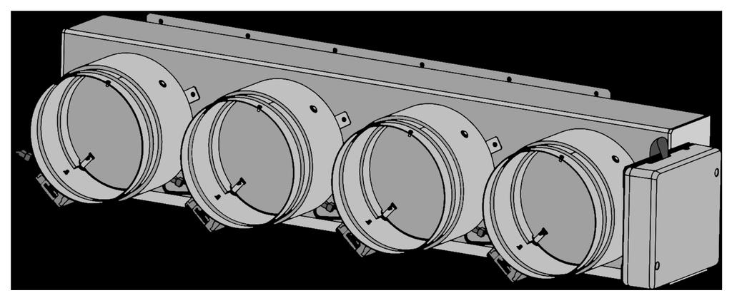
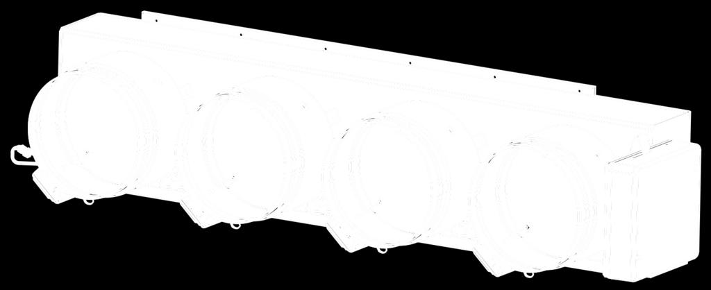
7 SYSTEM DESCRIPTION The Daikin Zoning Kit (DZK) is an optional accessory that increases the flexibility of the FXMQ and FBQ Indoor Unit fan coils. It allows multiple separate ducts to be connected to a fan coil and supply air to different individually controlled zones in a building. PRODUCT DIMENSIONS DZK030E4-3 DZK030E5-3 DZK048E4-3 7


8 DZK048E6-3 DZK Zoning Box B. Motorized damper A. Damper limitation adjustment B A 8
. Manages communication with the Daikin Interface Board.")

9 DZK CONTROL DZK Control Board This device manages all wired and wireless devices in the system, performing the following functions: Controls and manages the status of each thermostat or controller. Controls the position of the motorized dampers. Control of auxiliary heat (up to two stages). Manages communication with the Daikin Interface Board. Controls the On/Off status, mode, fan speed, and set point of the Daikin Indoor unit. DZK Interface Board This unit integrates the Daikin indoor unit with the DZK Control Board. The DZK Interface Board includes an energy efficiency control algorithm that is controlled with the Wired Thermostat, including the following functions: Automatically changes the indoor unit operation mode (Ventilation, Cooling, Heating, or Dry) from the DZK system s Main Wired Thermostat. Temperature setting for the indoor unit based on the overall demand of the DZK zone thermostats. Defrost function: In heating mode, when user set point temperatures are satisfied, instead of setting the Daikin unit to OFF, a 60 F set point is set. This function is set by means of DIP-switch configuration. 9
. Configurable set point range for Cooling and Heating.")
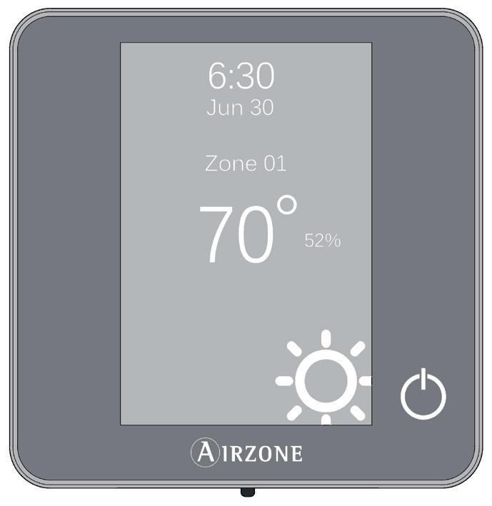
10 Wired Thermostat Color graphic interface with capacitive touch screen for controlling zones in DZK systems. Finished in steel and glass. Powered by DZK Control Board. Wall mounted. Functionalities: Available languages: English, French and Spanish. Control of set point temperature (increment of 1 F/0.5 C). Configurable set point range for Cooling and Heating. Room temperature and relative humidity sensing and display. Operation mode, User mode and Airflow control (Only available to the Main Wired Thermostat). Timer function. Time schedules programming. Remote access to other zones of the system. Configurable as Main or Zone thermostat. Wireless Thermostat Graphic interface with low-energy e-ink screen and capacitive buttons for controlling zones in DZK systems. Finished in steel and glass. Wireless communications. Powered by CR2450 button battery (included). Wall mounted. Functionalities: Available languages: English, French and Spanish. Control of set point temperature (increment of 1 F/0.5 C). Configurable set point range for Cooling and Heating. Room temperature and relative humidity sensing and display. Timer function. 10
. Wall mounted. Functionalities: On/Off control of the zone. Control of base set point temperature with an increment of ± 1 F/0.")

 - Compatible with BACnet/IP (ISO16484-5) The DZK")
11 Wireless Lite Thermostat Thermostat with capacitive buttons for controlling the temperature of the zones in the DZK systems. Finished in steel and glass. Wireless communications. Powered by CR2450 button battery (included). Wall mounted. Functionalities: On/Off control of the zone. Control of base set point temperature with an increment of ± 1 F/0.5 C (default value) or ± 2 F/1 F, up to a limit of ±6 F/3 C. The increments are configurable through Main Wired Thermostat. This base set point temperature can be configured through any Wired Thermostat. Room temperature and relative humidity sensing. DZK BACnet Interface The DZK BACnet Interface allows a Building Management System to control all variables of the DZK systems. The DZK BACnet Interface uses a standard open protocol based on ASHRAE Standard 135, and its objects are: - Compatible with BACnet (ANSI /ASHRAE-135) - Compatible with BACnet/IP (ISO ) The DZK BACnet Interface is a Plug&Play device for DZK, and it allows for control and monitoring of the following variables: Indoor Unit status. Fan status and Fan Speed. Auxiliary Heat stages status. Global Ventilation status. Operation Mode Control status. On/Off control for each zone. Set point setting for Cooling and Heating for each zone. Room Temperature in each zone. Local Ventilation activated/deactivated for each zone. Auto (Follow Schedule) activate/deactivate. Unoccupied Mode Status. Vacation Mode activate/deactivate. Opening Damper Status for each zone. Indoor Unit and DZK errors. 11


12 DESCRIPTION, INSTALLATION AND CONNECTION OF THE COMPONENTS GENERAL RECOMMENDATIONS Closely follow the instructions on this manual to avoid installation and maintenance issues. The system should only be installed by qualified personnel. Never use solid wire to install the system. This is a communication device and requires the use of communication cables. While connecting the devices, be sure the system is not powered. Follow the local installation regulations for low and high voltage installation. The recommended specifications for the cable to install this system are: 4 wires, stranded, AWG 20, plenum and shielded. When connecting to other systems fed with high voltage, only use the A and B contacts of the communication bus. It is not recommended to connect the + and contacts, nor the ground. Follow the color codes and polarity indications in the system components. Do not run the bus cable near high power cables or near electrical motors to avoid electromagnetic interference in the system communications. Use the following recommendations to locate the thermostats: h= 5 ft The temperature operating range is: 32 to 122 F (0 to 50 C). The humidity operating range is: 5 to 90% (non-condensing). 12
13 If upon receiving the unit it is determined that one of the outlets will not be used, take the following actions: 1. Install the unit and wiring required to start with the Wired Thermostat configuration. The unit should have all dampers open. 2. Configure the Wired Thermostat. Once the thermostat is assigned to a zone, all other dampers will close except for the zone that is assigned to the Main Wired Thermostat. 3. At this time, disconnect the motor cable from the outlet that will not be used. 4. Permanently seal the outlet using the supplied plug and follow the local installation recommendations. DZK ZONING BOX Dampers are numbered starting with number 1 next to the Zoning box control board. Keep in mind: make sure that the zoning box is in its correct position. (Actuators at the bottom) Assembly The Zoning Box allows for a fast and simple connection to Daikin indoor units FBQ_P and FMXQ_P. Models FBQ PVJU FXMQ PBVJU FBQ PVJU FXMQ PBVJU Damper Size Number of Dampers Follow the steps listed below to make an easy and reliable DZK installation: The adaptor is shipped with the dampers fully open. One of them includes a cover to be used in case one of the dampers is not used. If the damper is not used, the contractor needs to be sure that the cover will stay in place. If all dampers are used, take the cover off and store it. 13


 in the")


14 Insert a sharp pointed object through the frame holes and the frame sealing to facilitate the location of the setting holes used to assemble the zoning box to the indoor unit. Remove the indoor unit collar. Insert a screw (not fully tightened) in the bottom corners of the indoor unit as shown in the following figure: Sit the zoning box on the screws as shown below, and then affix the box using the remaining screws. Attach each zone s duct with its assigned damper. Follow the local recommendations to insulate and seal the ductwork with the damper. Make a cutout along the duct to keep the motor outside of the insulation. 14


15 Keep in mind: to maximize the air flow for each damper, the best way to disable dampers is to start disabling from the ends to the center, due to the position of the DZK related to the air handler. Use of the insulated stopper. If a damper is not used in the installation, proceed as follows: Make sure the damper is closed before installing the insulated stopper. (The damper will close as soon as the first zone is assigned.) Keep in mind: when one or more dampers are disabled, it is recommended to adjust the Airflow control parameter to avoid overpressure on the active dampers and ductwork Check that the power cable is disconnected for the damper motor that will not be used. Check that the damper remains airtight with the power ON and the fan running. 15
16 Damper setting The dampers included in the zoning box have a built-in control system that allows you to manually set the maximum and minimum opening of each damper according to the needs of each installation. Average Flow (REG) Due to the unique characteristics of each Daikin indoor unit supply opening with respect to the dampers of the box, the flow distribution is not identical in each damper. The central dampers receive more airflow than the others and the damper in the first and last position receives the least amount of air flow. This zoning box offers maximum aperture adjustment which balances the flow of each damper to the needs of the installation. By default, the dampers are configured with a maximum opening at Position I. To adjust the control of the dampers proceed as follows: The damper must be completely closed to mechanically adjust its flow. To make this adjustment, create demand in all zones so that the indoor unit runs at maximum capacity. Then deactivate the zone to be adjusted, and verify that there is no air supplied to that zone. With the damper closed, place the lever marked REG in the actuator to the desired open position. There are 4 position (I, II, III, and IV) with position I being completely open and position IV having the slightest opening. Perform the setting of the dampers by changing the lever REG position, beginning with the central damper opening and ending with damper No. 1 (Closest to the zoning box control board). The reduced flow in the central dampers will increase the flow of the dampers at the ends. REG lever 16


17 The use of an anemometer verifies that the flow in each grille is within the installation requirements. A-M lever Minimum Air (A-M) Similarly, the zoning box allows a minimum air opening for each damper, if needed. By default, the Position a damper is configured in the full-close position. To adjust minimum air for any damper, proceed as follows: Check that the dampers are wide open. To do so, set the system to Stop user mode, from the Main Wired Thermostat. Perform the setting of the dampers by changing the lever A-M position beginning with the central damper opening of the box and ending with damper No. 1. (Closest to the zoning box control board). With the damper open, place the handle A-M in the desired open position. It has 4 positions (a, b, c and d) where position a" is fully closed and is "d" is the fully open. The use of an anemometer verifies that the flow in each grille is within the installation requirements. 17

18 Connection N Description DZK connection bus Wireless interface Reset system button Control for optional DZK BACnet Interface DZK Interface Board Actuator control outputs Alarm input (normally close) Protection probe input Heating stage 2 output Heating stage 1 output Power supply 1. DZK connection bus The DZK connection bus allows the connection of up to 6 Wired Thermostats. There are 3 connectors, each one with 5 contacts available, for connecting the expansion bus. The Wired Thermostat is connected to the DZK bus (Maximum of 2 Wired Thermostats per connector). Connect the cables to the connector contacts following the color code indicated below. Important: At least one Wired Thermostat is required for each DZK system, which can control up 6 zones. 2. Wireless interface This device provides the communication between the Zoning box control board and Wireless Thermostats and Wireless Lite Thermostats. 3. Reset system button If the whole system needs to be reset (normally a replacement board that has been used before, or at the request of the technical support as a last resource to fix a problem), press and hold SW1 until LED 19 stops flashing. A system reset will return all settings to default values and conditions. Keep in mind: once this sequence is started it cannot be interrupted and the Quick Setup process should be allowed to finish. 18

 When this input is open it will stop the Daikin indoor unit and close all dampers.")


19 4. Control for optional DZK BACnet Interface The DZK BACnet Interface allows the communication between the DZK zoning box and BMS BACnet/IP installation. 5. DZK Interface Board This Interface provides the communication between the DZK zoning box control board and Daikin Indoor unit, connecting to P1 P2. 6. Actuator control outputs These outputs are used to drive the damper actuators with 12VDC control for each damper. 7. Alarm input (normally closed) When this input is open it will stop the Daikin indoor unit and close all dampers. This input is shipped with a jumper in the connector that should be left in place unless an alarm input is connected. 8. Protection probe input This input is used to connect the supply temperature sensor. 9. Heating stages If the system includes Auxiliary Heat, when required by the heat demand, these outputs enable the first and second stages of Auxiliary Heat. The technical specifications for the 1 st and 2 nd Stage Aux. Heat relay are: I max. =1 24V, dry contacts. If higher power is required for control, use external contactors of appropriate capabilities. 10. Power supply Power supply 110/230 VAC line. The Zoning box control board is protected by a self-resettable fuse. This is an electronic component that does not require any action other than cycling the power to perform the reset. Connect the cables to the connector contacts following the code indicated below. 19
20 DZK INTERFACE BOARD Connection and configuration Complete the connections adhering to the following steps, in this order: 1. Disconnect the power supply from both the Daikin indoor unit and the DZK system. 2. Open the protective cover of the Daikin indoor unit, and locate the P1, P2 connection (to which the Daikin Navigation Remote Controller is connected). 3. Connect a two-wire cable to P1 P2 on the Indoor unit, in parallel with the Daikin navigation controller. 4. Connect the other end of this cable to the connector labeled P1 P2 on the DZK Interface Board mounted on top of the DZK Control Board, maintaining the polarity. Important: a Daikin navigation controller is required to be connected to the Daikin indoor unit in addition to the DZK thermostats. 5. Close the Daikin indoor unit s protective cover. 6. Configure the microswitchs as required. SW1 Algorithm SW1 Defrost ON* OFF - 4ºF/2ºC Set point +8ºF/4ºC OFF* 7. Power the Daikin indoor unit and the DZK system. Check the gateway LEDs (self-diagnosis). Note: Disable the Setback function using the Daikin controllers for a proper operation of the Airzone system. ON Algorithm function On Depending on the set points of the zones calling for demand and on the return air temperature, the IDU s set point is set to reach a more efficient performance and to avoid stratification in heating. Algorithm function Off IDU s set point is set depending on the set points of the zones calling for demand. Defrost function In heating mode, when all the zones are satisfied, instead of setting the Daikin unit to OFF, a 60 F set point is set. 20


21 DZK BACNET INTERFACE Installation The DZK BACnet Interface is a Plug&Play interface. Disconnect the terminal and snap the connector and the interface support tube as shown in the pictures: Note: This BACnet/IP device is connected to the BMS by Ethernet cable. BACnet typical layouts are as follows: Configuration Note: check with BMS vendor what device ID should be configured here to avoid conflict within BACnet network. From the main screen, press and hold the icon until the Enter pattern screen is displayed. Enter the sequence below to access the configuration menu, select the System settings and then select the BACnet setting. 21


 and the Port")


 - Subnet mask (default 255.")
 To configure them, access the IP")
22 Device ID and Port In the BACnet menu, press the icon. For the proper identification on the BACnet/IP network and operation of the DZK BACnet Interface, it may be required to modify the Device ID (by default 1000) and the Port parameter (by default 47808). These properties can only be modified locally from the Main Wired Thermostat. Note: device ID is unique per BACnet device. IP Configuration In the BACnet menu, press the icon. For the proper operation of the DZK BACnet Interface with the IP network, it is required to configure the following network parameters: - IP Address (default ) - Subnet mask (default ) - Gateway IP (default ) These properties can only be modified locally from the Main Wired Thermostat. To configure them, access the IP Configuration menu from the BACnet menu: 22


23 WIRED THERMOSTAT Installation The Wired Thermostat is available for wall mount. The wiring should not exceed 130 ft. (40 m) and stranded AWG20 shielded cable should be used. To mount the thermostat on the wall, take the following steps: Separate the back part of the thermostat from the wall support and make all the connections. Fix the back part of the thermostat to the wall. Place the display on the support once it is fixed. Wiring The Wired Thermostats are connected to the DZK connection bus of the DZK Control Board. Attach the wires with the terminal screws following the color code Important: Use a suitable screwdriver to press in the locking tabs. Important: perform the pairing of thermostat in their final location. Distances less than 18 inches between the thermostat and the control board can saturate the receivers and make the pairing impossible. WIRELESS AND WIRELESS LITE THERMOSTAT Installation The Wireless and Wireless Lite Thermostats are available for wall mount. The maximum distance between the Zoning box control board and the thermostat in clear line of sight is 130 ft. (40 m). To mount the thermostat on the wall, take the following steps: Remove the back of the thermostat and insert the CR2450 button battery. Fix the back part of the thermostat to the wall. Place the display on the support once it is fixed. 23


. Important: we recommend the use of top-brand batteries.")
24 Changing batteries When a Wireless Thermostat is running out of battery, it displays the icon on the screensaver. In the case of the Wireless Lite Thermostats, a warning message will be displayed on the Wired Thermostat. In order to know the zone of the Wireless Lite Thermostat(s) running out of battery press on the warning icon. To replace the battery, separate the thermostat from its support and replace the battery (CR2450). Important: we recommend the use of top-brand batteries. The use of low-quality batteries may reduce the duration of use. Remember to deposit the old battery into an appropriate recycling point. 24
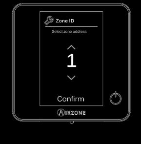
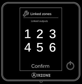
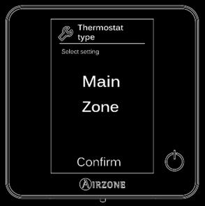
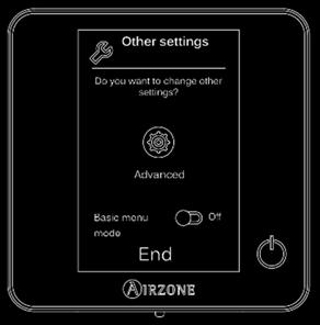
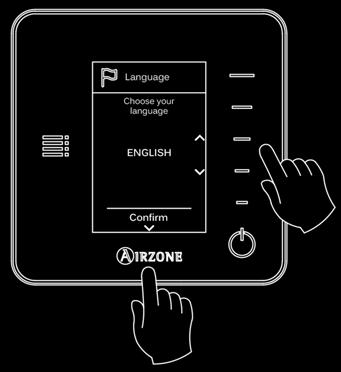
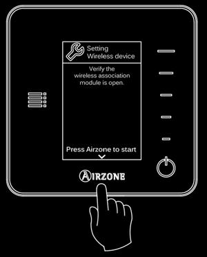
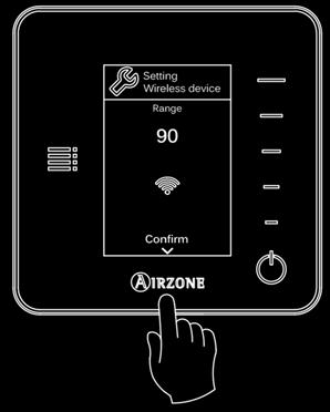
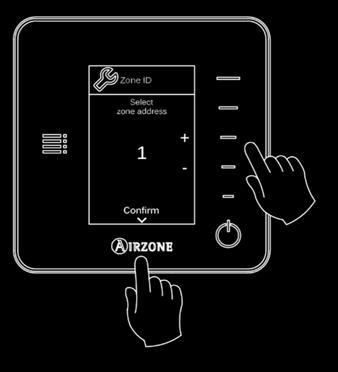
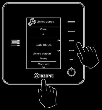
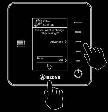
25 INITIAL CONFIGURATION IMPORTANT: To associate Wireless and Wireless Lite Thermostats, it is necessary to open the radio channel. To do that, press on SW1. The LED D19 will remain solid red. Once open, you have 15 minutes to make the association. If that period of time expires, start the process over again. Remember not to open more than one radio channel at the same time, it may alter the process. You can also open the channel association radio through the Main Wired Thermostat (see section System parameters). WIRED AND WIRELESS THERMOSTATS CONFIGURATION Language Select your language: English, French or Spanish. Important: once you start the process, it cannot be interrupted. Wireless Association (only Wireless Thermostat) Press Airzone to start seeking and confirm the wireless association. Verify the range is correct (30% minimum). Keep in mind: to access the main screen from the Wireless Thermostat screensaver, press on Airzone. Zone ID Select the zone associated to the thermostat. Zone 1 controls damper 1, zone 2 controls damper 2, and so on for up to 6 zones in the system. Linked Zones If necessary, the system allows you to associate more than one control output to a zone. It is possible to control multiple outputs from the same thermostat. Thermostat Configuration (only Wired Thermostat) Each DZK system must have one Wired Thermostat configured as the Main thermostat. Select the operation of the thermostat: - Main: controls all the parameters of the installation. - Zone: controls all the parameters of the zone. Note: given that only one thermostat can be configured as the Main thermostat, this parameter will not appear for selection if one thermostat in the system has been already configured as the Main thermostat. Other Settings Access the advanced settings to change other settings or activate the Basic Menu Mode if you want to. Note: When set to Basic mode, the user can control the following parameters: On/Off, set point, local ventilation and user settings. 25
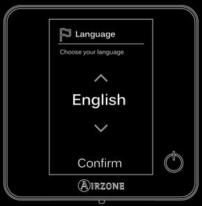
26 Wired Thermostat Wireless Thermostat 26


. If the association is correct, the LED will flash green 5 times. If it flashes red, it means the zone is already occupied.")
27 WIRELESS LITE THERMOSTAT CONFIGURATION Zone ID Select the zone associated to the thermostat by switching on the corresponding dip switch number. Remember: if you need to change the zone number, reset the thermostat, and start association process. Linked Zones If required, select other control outputs associated to the zone by adjusting the corresponding dip switches. The address zone will be the one with a lower value. Other Settings Configure other functionalities of the Wireless Lite Thermostat from the Advanced Configuration menu of any Wired Thermostat (refer to the Zone Parameters settings of the Wired Thermostat). If the association is correct, the LED will flash green 5 times. If it flashes red, it means the zone is already occupied. If it flashes red twice, it means the thermostat is out of range. Wireless Lite Thermostat Reset If you want to return your Wireless Lite Thermostat to factory values, pull down all the microswitchs. Press on and the LED will flash green twice when the reset process is completed. 27


. Note: when global ventilation is activated, a warning message will appear on the screensaver. Global Ventilation.")
28 ADVANCED CONFIGURATION Installation Manual Besides the quick configuration menu, the system has a number of configuration parameters to complete the installation. ADVANCED CONFIGURATION - WIRED THERMOSTAT To access the advanced configuration menu, follow the next steps: Press and hold From this menu you can change the system and zone parameters. System Parameters System ID. This option allows the installer to define the number of this DZK system within the whole installation. By default, the value is 1. The system displays the available IDs with a maximum value of 16. Note: If you have a DZK BACnet Interface, this parameter is not displayed and the address of the system is 1. Temperature SP Range. This menu allows you to change the maximum set point temperature for heating mode (66 F to 86 F / 18 C to 30 C, by default 86 F/30 C) and minimum set point temperature in cooling mode (64 F to 78 F / 18 C to 26 C, by default 64 F/18 C). Note: when global ventilation is activated, a warning message will appear on the screensaver. Global Ventilation. This menu allows you to activate/deactivate the fan mode in all zones when the system is not actively heating or cooling any zones. By default, the global ventilation is deactivated. When activated, the following settings are used to configure Global Ventilation: Every (min). Configure the length of the interval (in minutes) between periods of ventilation. Configurable from 5 to 40 minutes, in 5 minutes increments (by default, 15 minutes). 28
29 Run For (min). Configure the time duration that ventilation is activated (in minutes). Configurable from 5 to 20 minutes, in 5 minutes increments (by default, 10 minutes). Type of Opening. This menu allows you to enable or disable the modulating system dampers. Proportionally graduated in four steps, the opening or closing of the damper is based on the demand for zone temperature to adjust the flow rate. By default, the dampers are set for Modulating. If you select the Modulating option, select the desired damper and set the REG lever position, where position I is completely open and position IV has the smallest opening. Note: when the radio channel is opened, it will remain open for 15 minutes. Radio Channel. This option allows you to open the wireless channel association for connecting Wireless and Wireless Lite Thermostats to the Zoning box control board. By default, the radio channel is closed. Supply Temperature. This option allows the system demand to be ignored if the supply temperature exceeds a certain limit. The selectable heating cut out temperatures are F ( C). By default, the system will stop heating if the supply temperature reaches 129 F / 54 C. Away Mode Settings. This option configures the following parameters of the unoccupied user mode and the vacation user mode: - Hysteresis. If the set point temperature is surpassed by the differential defined, the zone will cease demand. Range: 2 to 7 F / 1 to 3.5 C in steps of 1 / 0.5 C. By default, 6 F / 3 C. - Override Time. Sets time that the zone will resume the selected away mode when the user touches the thermostat screen during an away period. Values: 10 to 120 minutes in steps of 10 minutes. By default, 60 minutes. 29
30 Auxiliary Heat. This menu is used to enable/disable the auxiliary heat. By default, the auxiliary heat is disabled. When auxiliary heat is enabled, the following parameters are used to configure the operation of the auxiliary heat: Configuration Menu. - Available Stages. Defines how many stages of auxiliary heat a system has. - First Supply Heat. If the setting for Auxiliary heat is 1 or 2, then the first system to supply heat must be defined as either: Heat Pump or Aux. Heat. o Fan Configuration. Select between Electric (Fan on) or Furnace (Fan off) option. If you select Electric option, define: First Stage Menu. Fan Delay (s). Defines the delay time (in seconds) to turn off the fan when there is no demand from the Auxiliary Heater. Possible values are 0, 45, 60 and 120 seconds. - First Stage Differential. Temperature that the system has to surpass to activate the first stage of auxiliary heat. Values: 2 to 10 F/1 to 5 C in increments of 1 F/0.5 C. By default, 2 F/1 C. - First Stage Hysteresis. Defines the hysteresis for the operation of the first stage. Values: 1-2 F/0.5-1 C in increments of 1 F/0.5 C. By default, 1 F/0.5 C. - Min. Time Exhausted. Minimum time that the Heat Pump must be active before the first stage of auxiliary heat can be activated. Possible values are 0, 45, 60 and 120 minutes. By default, 45 minutes. Second Stage Menu. - Second Stage differential. Temperature that the system has to surpass to activate the second stage of auxiliary heat. Values: 2 to 10 F/1 to 5 C in increments of 1 F/0.5 C. By default, 2 F/1 C. - Second Stage Hysteresis. Defines the hysteresis for the operation of the second stage. Values: 1-2 F/0.5-1 C in increments of 1 F/0.5 C. By default, 1 F/0.5 C. - Min. Time Exhausted. Minimum time that the first stage must be active before the second stage of auxiliary heat can be activated. Possible values are 0, 45, 60 and 120 minutes. By default, 45 minutes. Note: if the auxiliary heat is electrical and the installation is heat pump type, then the first one to supply heat must be Heat Pump in the DZK master system. 30
31 Autochange. This option allows the user to configure the three values that define the auto-changeover operation that sets the mode of the indoor unit. - Setpoint Differential. Defines the minimum differential between heating and cooling set points. For example, if set to 2 F, the system will force the cooling set point at least two degrees higher than the heating set point. Values: 0 to 7 F / 0 to 3.5 C in increments of 1 F / 0.5 C, by default 2 F / 1 C. - Mode Switching Protection (min). Defines the minimum run time before allowing a mode change. Possible values are 15, 30, 60 and 90 minutes. By default, 30 minutes. - Heat OVR Temp. If a zone has a higher heating demand than this temperature, the system reverts heating operation even if the cooling global demand exceeds the global heat demand. Possible values are: Off, 3 to 8 F / 1.5 to 4 C in increments of 1 F / 0.5 C. Default value: Off. Note: in case of system reset, it will return to default values. BACnet. This parameter displays the Device ID, the uplink port, the IP address, the subnet mask and the Gateway IP and allows you to modify them. Press on the value you want to change, modify it and then press to confirm. The values by default are: - Port: IP Address: Subnet Mask: Gateway IP: Room Temperature. This option allows the room temperature and relative humidity to be shown/hidden. By default, the room temperature is shown. Lite Step. This option configures the temperature increments (2 F/1 C or 1 F/ 0.5 C) of the base set-point for the Wireless Lite Thermostat. By default, 1 F/0.5 C. Note: the Remote Assistance parameter enables a qualified technician the remote access to your installation in order to perform a diagnose of it. Remote Assistance. This option enables/disables remote assistance. By default, remote assistance is disabled. Reset System (only available for the Main thermostat). This option resets the system and returns to factory settings. 31
32 Zone Parameters Linked Zones. Displays the linked zones and allows you to select the secondary control dampers associated with the thermostat. Thermostat Type. Configure the thermostat as Main or Zone. Note: it cannot be configured as Main if there is already another Main thermostat. Menu Mode. The thermostats can be set in Basic or Advanced mode (Advanced by default). When set to Basic mode, the user can control the following parameters: On/Off, set point, local ventilation and user settings. Offset. This option allows the user to apply an offset to the room temperature reading. The offset range goes from -5 to 5 F (-2.5 to 2.5 C). The default value is 0 F/ 0 C. This offset will always be applied to the measured room temperature of the zone. User Mode Setpoint. This option is used to configure the set point temperature of each user mode for each zone. - Comfort. Heating mode: 59 to 86 F/ 15 to 30 C, by default 68 F / 20 C. Cooling mode: 64 to 86 F/ 18 to 30 C, by default 75 F / 24 C. - Eco. Heating mode: 59 to 86 F / 15 to 30 C, by default 66 F / 19 C. Cooling mode: 64 to 86 F / 18 to 30 C, by default 84 F / 29 C. - Unoccupied. Heating mode: 59 to 72 F/ 15 to 22 C, by default 63 F/17.5 C. Cooling mode: 75 to 86 F/ 24 to 30 C, by default 81 F/27 C. - Vacation. Heating mode: 50 to 61 F/ 10 to 16 C, by default 50 F/10 C. Cooling mode: 84 to 96 F/ 29 to 35.5 C, by default 95 F/35 C. Weight. This option is used to set the weight of each zone for purposes of determining system operation. The weight of the zone will be used for calculating the mode (auto-change over) or for calculating heat demands when using auxiliary heat. It is an indicator of the size / importance of the zone. Possible values range from By default, the weighting is set to Auto and each zone's weight is automatically generated based on the number of zones. For example, if there are four zones, each zone's weight is automatically set to 25. If this option is disabled, the weight of the zone can be set manually. 32


33 Reset Thermostat. This option resets the thermostat and returns it to factory values. Keep in mind: to access the main screen from the Wireless Thermostat screensaver, press on Airzone. ADVANCED CONFIGURATION -WIRELESS THERMOSTAT To access the advanced configuration menu follow the following steps: Press once Press and hold Press and hold Linked Zones. Displays the linked the zones and allows you to select the secondary control dampers associated with the thermostat. Menu Mode. The thermostats can be set in Basic or Advanced mode. They are set in Advanced mode by default. These are the parameters you can control in Basic mode: On/Off, set-point temperature and local ventilation. Offset. This option allows the user to apply an offset to the room temperature reading. The offset range goes from -5 F to +5 F (-20.5 to -15 C). The default value is 0 F. This offset will always be applied to the measured room temperature of the zone. Weight. This option is used to set the weight of each zone for purposes of determining system operation. The weight of the zone will be used for calculating the mode (auto-change over) or for calculating heat demands when using auxiliary heat. It is an indicator of the size / importance of the zone. Possible values range from By default, the weighting is set to Auto and each zone's weight is automatically generated based on the number of zones. For example, if there are four zones, each zone's weight is automatically set to 25. Change from Manual to Auto if you want to automatically calculate the total weight of each zone. Reset Thermostat. This option resets the thermostat and returns it to factory values. 33
34 USER SETTINGS WIRED THERMOSTAT Press on icon to see all the shortcuts list: Units. Select temperatures to be displayed: Fahrenheit (default) or Celsius. Language. Select your language: English, French or Spanish. Brightness. Adjust the brightness, and enable or disable screen brightness when the screen saver is active. Date and Time. Press on the clock to set time, format type (12 or 24 hours) and enable daylight saving time. Press on the calendar to set the date. Information. Displays information about: Zone: Firmware, zone, association, actuator or status of the communications. System: Firmware, configuration and information about the controllers. Devices: Displays what elements are connected to the system. Warnings and errors on system incidents. Clean Screen. Select this option if you want to clean the screen. The screen will lock for a few seconds in order to help prevent changes when cleaned. ZONE SETTINGS ZONE SETTINGS - WIRED THERMOSTAT Press on to access this menu. You will see these settings: Timer. It is an auto power-off timer of the zone. You can select: OFF. Timer is not activated. 30. Thirty minutes after its activation, the zone will turn off. 60. Sixty minutes after its activation, the zone will turn off. 34
35 90. Ninety minutes after its activation, the zone will turn off. Lite Settings. This parameter defines base set-point temperature for zones with Wireless Lite Thermostat. Important: This parameter is available when navigating to a zone controlled by a Wireless Lite Thermostat by using a Wired Thermostat. ZONE SETTINGS - WIRELESS THERMOSTAT Keep in mind: to access the main screen from the Wireless Thermostat screensaver, press on Airzone. Important: in Heat Pump installations, it is recommended not to activate the global and local ventilation in a DZK zoning box connected to the master indoor unit. It may cause the Stop user mode to the rest of turn off the DZK zoning box. Press on to access this menu. You will see these settings: Local Ventilation. This option allows activation or deactivation of the fan mode the selected when the system is not actively cooling or heating any of the zones. Timer. Automatically switches off the zone after the defined time. You can select: OFF. Timer is not activated. 30. Thirty minutes after its activation, the zone will turn off. 60. Sixty minutes after its activation, the zone will turn off. 90. Ninety minutes after its activation, the zone will turn off. Information. Displays information about: Zone: Firmware, zone, association, actuator or status of the communications. System: Firmware, configuration and information about the controllers. Devices: Displays what elements are connected to the system. Zone navigation. Zone navigation will be available only when the Master thermostat is in error. Will be able to access, through the "All zones" option to the parameters: Set Point, Mode, User mode and Airflow to modify them. 35

36 COMMISSIONING STEPS TURN ON POWER TO ALL SYSTEM Wired and Wireless Thermostats. Verify that the first configuration screen is displayed. DZK Control Board. Verify that the LEDs status is correct. Note: when configuring the system, the opening LEDs of the actuator control outputs will turn on sequentially as the system checks proper functioning. Meaning D1 Data reception from BACnet interface connector Blinking Green D2 Data transmission from BACnet interface connector Blinking Red D3 Main control board internal bus activity Blinking Green D4 Data transmission from DZK connection bus Blinking Red D5 Data reception from DZK connection bus Blinking Green D11 Main control board power Solid Red Opening damper On Green Closing damper On Red 36


37 DZK Interface Board. Verify that the LEDs status is correct. Meaning D1 Interface power supply Solid Red D2 DZK Interface Board internal bus activity Blinking Green D3 Data transmission to Zoning box control board Blinking Red D4 Data reception from Zoning box control board Blinking Green D5 Data transmission to Daikin navigation controller Blinking Red D6 Data reception from Daikin navigation controller Blinking Green Wireless Lite Thermostat. Verify that the LED will flash green 5 times to confirm the association. DZK BACnet Interface. Verify that the LEDs status is correct. 37


38 Meaning Ethernet connected Blinking Green Ethernet activity Blinking Yellow D7 Data transmission from automation Blinking Red D8 Data reception from automation bus Blinking Green D9 Microswitch performance Blinking Green D10 Connected to the Internet Blinking Green D11 Network data transmission Blinking Red D12 Network data reception Blinking Green D13 Configured as IP address through DHCP On Red Configured as Fixed IP address Off Red D15 Power supply Solid Red COMMUNICATIONS WITH THE INDOOR UNIT MODES / TEMPERATURE Check that the Navigation Remote Controller receives the operation mode change from the zoning system. To verify that, change the operation mode on the Main Wired Thermostat and verify that the new mode appears in the Navigation Remote Controller. DZK Wired Thermostat Daikin Navigation Remote Controller Check that the Daikin Navigation Remote Controller receives the temperature changes from the zoning system. To do this, deactivate all thermostats but the Main Wired Thermostat. Change the Main Wired Thermostat set point, and verify that the set point in the Daikin Navigation Remote Controller follows the specified set point changes. 38 DZK Wired Thermostat Daikin Navigation Remote Controller
39 ZONE ASSIGNMENT Activate each thermostat, one at a time, and set it for demand by Zone Navigation menu (see the section Zone Navigation from the User s Manual). Verify that the zone where the thermostat is located is receiving air. Change the set point to eliminate the demand, and verify that the airflow stops. AIRFLOW CONTROL SELECTION Check the change of the fan speed depending on the number of demand zones with the Standard mode. Remember that the Airflow control function is available in the Main Wired Thermostat to adapt the velocity map according to the installation requirements. 2 speeds indoor unit Total weight (Zones calling demand) Speed Silence Standard Power Low High speeds indoor unit REG lever Total weight (Zones calling demand) Speed Silence Standard Power Low Medium High Check with an anemometer that the air supply to each zone is the desired amount. Verify the airflow with all zones open, and also with each zone individually open. Before mechanically adjusting the maximum opening (REG), ensure that the zone damper is closed. To do this turn off the zone to be adjusted while keeping any other zone calling demand. 39


40 OTHER CONFIGURATION PARAMETERS If the installation has Auxiliary Heat, verify that it is correctly installed and configured. Verify that the Operation Mode menu displays Emergency Heat as an option. If you use Auxiliary Heat, check the relay operation in the zoning box control board to ensure it is working properly (first Aux H1, then Aux H2). To verify, set the system calling demand for heat and keep in mind that there is an action delay. Turn off the system and verify that Aux H1 and Aux H2 are disabled. D6 D7 Meaning 1st Stage Auxiliary heat 2nd Stage Auxiliary heat Aux. Heat status On Off On Off Normal status On Off On Off Color Green Green 40
41 EXCEPTION CODES If there is any warning or error, it will be displayed on the screensaver. In case of Wired Thermostat, it also will be displayed on the main screen, press on to access the Error menu. WARNINGS Unoccupied Override. A zone has been activated while the user mode is set to Unoccupied. The system will start working in Comfort Mode, and the zone will be active for the configured Override time (configured in the Away mode settings, see section System parameters). When the override time has finished, the system returns to its previous status. Note: to replace the battery, see section Changing batteries. Global Ventilation. The global ventilation is activated. To set the activation intervals of the global ventilation and the duration of them (see section System parameters, Global ventilation). Lite Low Battery (only Wired Thermostat). The battery (CR2450) of a Wireless Lite Thermostat has approximately 2 weeks of life left. Check which Wireless Lite Thermostat is affected by this warning through the zone number displayed in the Warnings menu. Low Battery (only Wireless Thermostat). The battery (CR2450) has approximately 2 weeks of life left. ERRORS Error 1. Communication error with the DZK Control Board. Error 5. Temperature sensor is open. Error 6. Temperature sensor is short circuited. Error 8 (only Wired Thermostat). Wireless Lite Thermostat not found. Error 9. Communication error between the DZK Interface Board and the DZK Control Board. Error 10. Communication error between the DZK BACnet interface and the DZK Control Board. Error 11. Communication error between the DZK Interface Board and the AC indoor unit. AC unit error. See the section Errors in Wired and Wireless Thermostats, to know the actions to be taken in these cases. 41

42 AUTO DIAGNOSTICS DZK CONTROL BOARD AUTO DIAGNOSIS Installation Manual The Zoning Box Control Board has LED s integrated on the DZK Control Board that provide information of abnormal conditions. Meaning D1 Data reception from DZK BACnet Interface connector Blinking Green D2 Data transmission from DZK BACnet Interface connector Blinking Red D3 Main control board internal bus activity Blinking Green D4 Data transmission from DZK connection bus Blinking Red D5 Data reception from DZK connection bus Blinking Green D6 1st Stage Aux. Heat Activated Switches Green D7 2nd Stage Aux. Heat Activated Switches Green D10 Wireless data packets reception Switches Green D11 Main control board power Solid Red D18 Wireless thermostat associated Solid Green D19 Association channel: active Solid Red Opening damper On Green Closing damper On Red LED D3 does not blink - Verify that the Control Board is powered. - If the LED 11 is ON, the control board is faulty. Contact Technical Support. 42
43 LED D5 does not blink - The board is not receiving information from the Wired Thermostat. Verify the wiring between the Wired Thermostat and the Control Board. Never use solid wires for this connection. LED D11 is not ON - Verify that the Control Board is powered. DZK INTERFACE BOARD AUTO DIAGNOSIS DZK Interface Board has integrated LED s that provide information about abnormal conditions. LED D1 is not ON Meaning D1 Interface power supply Solid Red D2 DZK Interface Board internal bus activity Blinking Green D3 Data transmission to Zoning box control board Blinking Red D4 Data reception from Zoning box control board Blinking Green D5 Data transmission to Daikin navigation controller Blinking Red D6 Data reception from Daikin navigation controller Blinking Green - Verify the AC Unit Power Supply. - Verify the correct connection between the Daikin Indoor unit and the DZK Interface Board. LED D2 does not blink - Contact Technical Support. LED s D3/D4 do not blink - Check the connection between the DZK Interface board and the DZK Control Board. LED s D5/D6 do not blink - Check the correct connection between the Daikin Indoor unit and the DZK Interface Board. 43
44 DZK BACNET INTERFACE AUTO DIAGNOSIS The DZK BACnet Interface have integrated LEDs that detect unusual operations. Installation Manual All LEDs are On Meaning Ethernet connected Blinking Green Ethernet activity Blinking Yellow D7 Data transmission from automation Blinking Red D8 Data reception from automation bus Blinking Green D9 Microswitch performance Blinking Green D10 Connected to the Internet Blinking Green D11 Network data transmission Blinking Red D12 Network data reception Blinking Green D13 Configured as IP address through DHCP On Red Configured as Fixed IP address Off Red D15 Power supply Solid Red - Verify the correct connection between the DZK Control Board and the DZK BACnet Interface. - Contact Technical Support. 44

45 NAVIGATION GUIDE WIRED THERMOSTAT NAVIGATION GUIDE 45

46 WIRELESS THERMOSTAT NAVIGATION GUIDE 46

 and (B/ -) is correct (1.8 Vdc).")
47 TROUBLESHOOTING ERRORS IN WIRED AND WIRELESS THERMOSTATS Error 1 (Wired Thermostat) - Communication error with the DZK Control Board This incident blocks the control of the zone. Check this error is not common to all thermostats. If so, verify the proper operation of the DZK Control Board. To solve this incident check: 1 DZK Control Board status: Correctly powered. 2 DZK Control Board status: Expansion bus LEDs are operating properly (see section Zoning box control board auto diagnosis). 3 Connection: Verify the polarity of the DZK Control Board and thermostat connectors. 4 Wiring: Check that the voltage between the poles (A/ -) and (B/ -) is correct (1.8 Vdc). 5 6 Restart the zone and re-associate it with the system: Press on Reset to restart the device. If the error persists, press and hold on and reset the thermostat. Restart system: If the system is restarted, this error may be displayed in the thermostats at the beginning of the process. This message should disappear after around 30 seconds. Error 1 (Wireless Thermostat) - Communication error with the DZK Control Board This incident blocks the control of the zone. Check this error is not common to all thermostats. If so, verify the proper operation of the DZK Control Board. To solve this incident check: 1 Thermostat status: Check the signal range of the thermostat. Move the thermostat closer to the DZK Control Board. If that way the communications are reestablished, it means it is necessary to relocate it permanently as it was out of range. 2 DZK Control Board status: Correctly powered. 3 DZK Control Board status: Proper operation of the LED of wireless communication (see section Zoning box control board auto diagnosis). 47

48 4 5 Restart the zone and re-associate it with the system. To do this, press and hold on restart the start-up configuration process. Keep in mind: To associate the thermostat, first open the association radio channel pressing the SW1 at the DZK Control Board or from any Wired Thermostat, activating the Radio channel parameter inside Advanced Settings, system parameter. Restart system: If the system is restarted, this error may be displayed in the thermostats at the beginning of the process. This message should disappear after around 30 seconds. and Error 5 - Temperature sensor is open The zone ceases to measure the room temperature, therefore the zone cannot generate demand. Replace the device. Error 6 - Temperature sensor is short circuited The zone ceases to measure the room temperature, therefore the zone cannot generate demand. Replace the device. Error 8 (Wired Thermostat) - Wireless Lite Thermostat not found The zone ceases to measure the room temperature of an associated Wireless Lite Thermostat, therefore the zone cannot generate demand. Check which Wireless Lite Thermostat is not working properly. To solve this incident check: 1 Power supply: Check the battery and replace it if necessary. 2 Verify the thermostat microswitch corresponds with the zone associated. If not, activate it using the tab with the value needed. Keep in mind: To associate the thermostat, first open the association radio channel pressing the SW1 at the DZK Control Board or from any Wired Thermostat, activating the Radio channel parameter inside Advanced Settings, system parameter. 48

.")

49 Error 9. Communication error between the DZK Interface Board and the DZK Control Board The system loses communication with the AC unit. The system will open all the zones and deactivate the control from the thermostats, only allowing the operation of the unit from the Daikin thermostat. To solve this incident check: 1 2 Verify the DZK Interface Board is properly connected to the AC unit port of the DZK Control Board. Check the status of the LEDs of the DZK Interface Board (see section DZK Interface Board auto diagnose). Error 10 - Communication error between the DZK BACnet Interface and the DZK Control Board The system loses communication with the DZK BACnet Interface. To solve this incident check: 1 2 Verify the DZK BACnet Interface is properly connected to the AC unit port of the DZK Control Board. Check the status of the LEDs of the DZK BACnet Interface (see section DZK BACnet Interface auto diagnose). 49


50 Error 11 - Communication error between the DZK Interface Board and the AC indoor unit The system loses communication with the AC unit. The system will open all the zones and deactivate the control from the thermostats, only allowing the operation of the unit from the Daikin thermostat. To solve this incident check: 1 Verify if the AC unit is powered. To do this, check the thermostat of the AC unit is ON Verify the AC unit operates properly by itself. To do this, disconnect the AC unit DZK system and select the unit from the thermostat from the AC unit. Connection: Check the polarity and connection of the DZK Interface Board connectors and the indoor unit. Check the status of the LEDs of the DZK Interface Board (see section DZK Interface Board auto diagnose). AC unit error Check the type of error displayed on the Daikin Navigation Remote Controller and follow the instructions provided by the manufacturer. ERRORS IN WIRELESS LITE THERMOSTAT Status LED blinking red quickly - Communication error with the Zoning box Main controller This incident blocks the control of the zone. Check that "Error 1" is not displayed on all thermostats. If so, verify the proper operation of the main board. To solve this incident check: 1 Thermostat status: Check the signal range of the thermostat. Move the thermostat closer to the Main control board. If communication is reestablished, it means that the thermostat was out of range and must be permanently relocated within range. 2 DZK Control Board status: Correctly powered. 3 DZK Control Board status: Proper operation of the LED of wireless communication. 50


51 4 5 Restart the zone and re-associate it with the system. To do this, pull down all the microswitchs, reinsert the thermostat in its base and press on the thermostat. The LED will flash green twice when the reset process is completed. Keep in mind: To associate the thermostat, first open the association radio channel pressing the SW1 at the DZK Control Board or from any Wired Thermostat, activating the Radio channel parameter inside Advanced Settings, system parameter. Restart system: If the system is restarted, this error may be displayed in the thermostats at the beginning of the process. This message should disappear after around 30 seconds. MORE SYSTEM INCIDENCES Wired Thermostat does not light up 1 Verify the cable connection between the Wired thermostat and the DZK Control Board (see section Wired Thermostat, Wiring). Never use solid wire for this connection. 2 Verify that voltage between the poles (A/ -) and (B/ -) is correct (1.8 Vdc) The zone controlled from the Wired Thermostat cannot be remotely accessed. After 45 minutes, its damper(s) will open and remain open until the problem is fixed. From any other zone thermostat, accessing the remote zones by selecting All zones will allow you to change the Operation Mode until the Wired Thermostat returns to normal operation. See the User manual. If the thermostat is replaced, only perform the initial configuration (see section Initial configuration). All other parameters and settings will be recovered automatically from the Control Board. Wireless Thermostat does not light up 1 Check the battery and replace it if necessary. 51
52 2 3 The zone controlled from the Wireless Thermostat cannot be remotely accessed. After 45 minutes, its damper(s) will open and remain open until the problem is fixed. If the thermostat is replaced, only perform the initial configuration (see section Initial configuration). All other parameters and settings will be recovered automatically from the DZK Control Board. The AC unit does not start even if everything is OK. After setting any mode, the Wired Thermostat shows User mode STOP 1 Verify that there is a jumper between the contacts of the Alarm connector (see section DZK Zoning box, Connection). When accessing Remote zones, one of them is not listed 1 2 Verify that the thermostat of the zone missing is working correctly. To this end, activate/deactivate the zone and check that the damper opens/closes correctly. The zones controlled for Wireless Thermostats or Wireless Lite Thermostats. After a power supply failure, it can take up to 4 minutes to have all the zones remotely accessible. On activating the zone, no air is supplied to its grille(s) if the fan coil is on Verify that the damper assigned to the thermostat is not blocked by the insulation stopper (see section DZK Zoning box, Assembly). Verify that the motor is electrically connected properly. There is a connection at about 4 inches from the actuator (see section DZK Zoning box, Connection). Verify in the actuator connection indicated above, that when demand is created from the thermostat, there are 12VDC between the contacts indicated above. This voltage will be present for about 5 seconds (see section DZK Zoning box, Connection). Verify that the zone assigned to the thermostat is the correct one. If it is not the correct damper, proceed to reset the incorrectly assigned thermostats and reassign to the correct zones. To reset the thermostats, follow these steps: - Wired Thermostat: Advanced configuration menu > Wired Thermostat > Zone parameters. - Wireless Thermostat: Advanced configuration menu > Wireless Thermostat. - Wireless Lite Thermostat: Wireless Lite Thermostat reset. In order to re-configure the thermostats, see section Initial configuration. If one or more zones do not control the temperature 1 Verify that the User mode is not Stop Verify room and set point temperatures in the non-working zone thermostat to see if it is creating demand. Verify that the damper actuator is connected properly at about 4 inches from the actuator (see section DZK Zoning box, Connection). Verify that the LEDs D5 and D6 located in the DZK Interface Board mounted over the Control Board are blinking (see section DZK Interface Board auto diagnosis). If D5 and D6 do not display normal behavior (constant blinking), verify the wiring between the DZK Interface Board and the Indoor Unit (see section DZK Interface Board, Connection and configuration). 52
53 5 Verify that no ERROR number is shown on the screen (see section DZK Exception codes, Errors and section Errors in Wired and Wireless Thermostats). The damper-modulating functionality does not work as expected 1 Verify that the damper REG level is located as configured in the Type of opening parameter (see section Damper setting and section System parameters). In Heat mode, when trying to change to Cool mode, the thermostat returns to Heat mode 1 The operation mode in the installation is controlled by the Daikin master indoor unit. The operation mode can only be changed from the DZK Main Wired thermostat connected to Daikin master indoor unit. In Heat Pump installations, the DZK zoning box connected to a slave indoor unit, changes to Stop mode 1 This is caused by the incompatibility between the subordinate unit mode and the master unit. Check the master unit is not operating in Fan mode (see User manual). Defrost mode on the indoor unit don t work properly 1 If the Daikin indoor unit has start/stop cycles in periods shorter than 30 minutes, set the dip switch #2 in the DZK Interface Board to ON. The DZK system does not detect the DZK BACnet Interface 1 Verify that the LED D9 is blinking and LEDs D7 y D8 are alternately blinking (see section DZK BACnet Interface auto diagnosis). If the above is not displayed, check the correct connection of the gateway on the DZK Control Board, verifying the 4-pin connector. The Interface for use in BACnet cannot be connected 1 Verify that LEDs situated on the Ethernet connector (see section DZK BACnet Interface auto diagnosis) are blinking, and those in the Ethernet connector are active. If the above is not true, check that the Ethernet cable is properly connected The indoor unit starts with the system set on off (off or user mode on Stop) 1 Verify that the Setback field setting on the Daikin indoor unit is disabled (see section DZK Interface Board, Connection and configuration). 53

54 WIRING DIAGRAM 54
55


56 Phone: (855)
5.5. Other configuration parameters EXCEPTION CODES AUTO DIAGNOSTICS Zoning box control board
 Table of contents Page 1. WARNINGS, ENVIRONMENTAL POLICY, AND CERTIFICATIONS... 5 1.1. Warnings... 5 1.2. Environmental Policy... 5 1.3. FCC Regulatory Notices... 6 1.4. INTERTEK / UL Regulatory Notices...
Wireless Thermostat (WTS10) Keypad Operation Guide
 Keypad Operation Guide") Keypad Operation Guide This Guide is intended to provide basic instructions for operating the thermostat from its on-board user interface prior to it being commissioned into the wireless ControlScope network.
Keypad Operation Guide This Guide is intended to provide basic instructions for operating the thermostat from its on-board user interface prior to it being commissioned into the wireless ControlScope network.
RGR150 USER S MANUAL. Wireless Rain Gauge with Thermometer and Clock
 RGR150 manual-final-091908:layout 1 9/19/08 8:59 AM Page 1 RGR150 USER S MANUAL Wireless Rain Gauge with Thermometer and Clock INTRODUCTION Thank you for selecting this Wireless Rain Gauge. This device
RADIANT HEATING AND COOLING SYSTEMS CLIMATE CŎNTROL ZONING SYSTEM INSTALLATION GUIDE. Climate Cŏntrol Zoning System Installation Guide
 RADIANT HEATING AND COOLING SYSTEMS CLIMATE CŎNTROL ZONING SYSTEM INSTALLATION GUIDE Climate Cŏntrol Zoning System Installation Guide Uponor Climate Cŏntrol Zoning System Installation Guide Published by
2018 thesimple, Inc.
 TM User Guide 2018 thesimple, Inc. Introduction The Simple thermostat supports supports 2 heating stages and 2 cooling stages for conventional systems, and 2 heating/cooling stages for heat pumps, with
2017 EcoFactor, Inc.
 User Guide 2017 EcoFactor, Inc. Introduction The thermostat supports up to 2 stages of heating and 2 stages of cooling for conventional systems, and 2 stages of heating/ cooling for heat pumps, with and
Daikin ENVi Thermostat installation overview
 Daikin ENVi Thermostat installation overview RESIDENTIAL LIGHT COMMERCIAL COMMERCIAL Presenter s Name Presenter s Title Daikin ENVi system overview (web based thermostat) Slide 2 Daikin ENVi System Overview
MODEL DZSP/ SZSP-1440 AIRCELL
 ACCM2-0513 55W30-AC0118 MODEL DZSP/ SZSP-1440 AIRCELL CONTROL MANUAL Control Adjustment and Operation Instructions CONTROL OVERVIEW/STANDARD FEATURES INITIALIZATION Section 1: Firmware blink code... 2
EW 40 Wireless Fan Control
 Installation & Operating Manual EW 40 Wireless Fan Control USA CAN Product Information... Chapters 1 + 2 Mechanical Installation... Chapter 3 Electrical Installation... Chapter 4 Start Up and Configuration...
Model: v2 Quick Setup Guide DC: Atomic Projection Alarm with Indoor and Outdoor Temperature
 Model: 616-146v2 Quick Setup Guide DC: 090116 Atomic Projection Alarm with Indoor and Outdoor Temperature Snooze/Backlight BUTTONS Time, Alarm with Snooze, & Calendar Projection Arm Rotates 180 Indoor/Outdoor
Product Manual SZ1022/SZ1031/SZ1035/
 Product Manual SZ1022/SZ1031/SZ1035/ Conventional Heating & Cooling Thermostats Communicating Thermostats Description The SZ1022, SZ1031, and SZ1035, are microprocessorbased mable thermostats designed
INSTRUCTION MANUAL Z-WAVE DIMMER 12387
 INSTRUCTION MANUAL Z-WAVE DIMMER 12387 Z-Wave DIMMER BASICS The Kichler Z-Wave full range dimmer is designed to allow your Kichler Design Pro LED fixtures to communicate with one another as well as to
RS332N BUTTON OPERATION INTRODUCTION. Installation and Operation Instructions for REMOVING THE THERMOSTAT FROM THE BACKPLATE
 Installation and Operation Instructions for RS332N 3-Heat / 2-Cool Non-Programmable Setback Thermostat with the Industry s Most Advanced Remote Sensor Bus for Gas, Electric, & Heat Pump Systems www.robertshawclimate.com
Pioneer Z100 Smart Thermostat Operating and Installation Manual
 Pioneer Z100 Smart Thermostat Operating and Installation Manual AW000515-B Page 2 Operating and Installation Manual Congratulations on the purchase of your new thermostat. It has been designed for easy
WIRELESS TEMPERATURE & HUMIDITY STATION INSTRUCTION MANUAL
 WIRELESS TEMPERATURE & HUMIDITY STATION INSTRUCTION MANUAL MODEL: S82967 DC: 071118 FIND MANUALS, FAQS, AND MORE UNDER THE SUPPORT TAB HERE: www.lacrossetechnology.com/s82967 TABLE OF CONTENTS 3. Power
INSTRUCTIONS OPERATING BLUETOOTH CAPACITIVE TOUCH THERMOSTAT MODEL COOL/FURNACE COOL/FURNACE/HEAT PUMP
 BLUETOOTH CAPACITIVE TOUCH THERMOSTAT OPERATING INSTRUCTIONS 3316420.XXX MODEL COOL/FURNACE COOL/FURNACE/HEAT STRIP COOL/FURNACE/HEAT PUMP Read these instructions carefully. These instructions MUST stay
Model: Quick Setup Guide DC: Atomic Projection Alarm Clock. Projection Lens. Buttons. Snooze/Backlight
 Model: 616-143 Quick Setup Guide DC: 083017 Atomic Projection Alarm Clock Snooze/Backlight Projection Lens Projection Arm Rotation (Front and Back) Buttons Projection Focus 5.0 VAC Power Jack 616-143 www.lacrossetechnology.com/support
WIRELESS MULTI-ZONE DIGITAL THERMOMETER WITH RADIO CONTROLLED CLOCK. Model No (SF Version) Instruction Manual
 Instruction Manual") WIRELESS MULTI-ZONE DIGITAL THERMOMETER WITH RADIO CONTROLLED CLOCK Model No. 91049-1 (SF Version) Instruction Manual BASE STATION REMOTE SENSOR FEATURES AND SPECIFICATIONS BASE STATION Indoor / RF outdoor
WIRELESS MULTI-ZONE DIGITAL THERMOMETER WITH RADIO CONTROLLED CLOCK Model No. 91049-1 (SF Version) Instruction Manual BASE STATION REMOTE SENSOR FEATURES AND SPECIFICATIONS BASE STATION Indoor / RF outdoor
Honeywell. Wireless Rain Gauge with Indoor. Temperature (TC152) USER MANUAL TABLE OF CONTENTS INTRODUCTION 3 PRODUCT OVERVIEW 4 REMOTE RAIN GAUGE 7
 USER MANUAL TABLE OF CONTENTS INTRODUCTION 3 PRODUCT OVERVIEW 4 REMOTE RAIN GAUGE 7") TABLE OF CONTENTS INTRODUCTION 3 PRODUCT OVERVIEW 4 REMOTE RAIN GAUGE 7 BEFORE YOU BEGIN 9 BATTERY INSTALLATION 10 LOW BATTERY WARNING 11 HOW TO USE THE TABLE STAND 11 GETTING STARTED 11 Honeywell Wireless
TABLE OF CONTENTS INTRODUCTION 3 PRODUCT OVERVIEW 4 REMOTE RAIN GAUGE 7 BEFORE YOU BEGIN 9 BATTERY INSTALLATION 10 LOW BATTERY WARNING 11 HOW TO USE THE TABLE STAND 11 GETTING STARTED 11 Honeywell Wireless
Model: Av2 Quick Setup Guide DC: Atomic Projection Alarm Clock
 BUTTONS Model: 616-146Av2 Quick Setup Guide DC: 111815 Atomic Projection Alarm Clock Snooze/Backlight Time, Alarm with Snooze Projection Arm Rotates 180 Indoor Temperature + Trends Moon Phase + Calendar
Installation, Configuration and User Manual
 Model 8826 System Controller Model 8826 System Controller Installation, Configuration and User Manual READ AND SAVE THESE INSTRUCTIONS WELCOME Thank you for choosing the Aprilaire HVAC Automation System.
User s Manual
 997-060180-4e User s Manual 8403-060 Menu Driven Display 1120-445 I. CONTROLLER OPERATION ADJUSTING TEMPERATURE (Temporary Override when in Programmable mode) 1. Before you can adjust the temperature,
Atomic Digital Clock with Temperature and Moon Phase
 Atomic Digital Clock with Temperature and Moon Phase For online video support: http://bit.ly/laxtechtalk Model: 513-1417AL D.C. 122016 Protected under U.S. Patents: 5,978,738 6,076,044 RE43903 Setup Power
Fume Hood Operating Display Panel
 Desigo TRA Fume Hood Operating Display Panel QMX3.P87 The Operating Display Panel (ODP) is the interface between the operator and the DXR Fume Hood Controller (FHC). LCD display for volume flow setpoint,
Model: Quick Setup Guide DC: Atomic Projection Alarm Clock. Projection Lens. Buttons. Snooze/Backlight
 Model: 616-143 Quick Setup Guide DC: 051916 Atomic Projection Alarm Clock Snooze/Backlight Projection Lens Projection Arm Rotation (Front and Back) Buttons Projection Focus 5.0 VAC Power Jack Battery Cover
Wireless Rain Gauge with Indoor Temperature
 TABLE OF CONTENTS INTRODUCTION 3 PRODUCT OVERVIEW 4 7 BEFORE YOU BEGIN 9 BATTERY INSTALLATION 10 Wireless Rain Gauge with Indoor Temperature LOW BATTERY WARNING 11 HOW TO USE THE TABLE STAND 11 GETTING
Ion Gateway Cellular Gateway and Wireless Sensors
 Page 1 of 9 Account & Network Setup If this is your first time using the Ion Gateway online system site you will need to create a new account. If you have already created an account you can skip to the
Net/X US32 Universal Setback Communicating Thermostat
 Installation and Programming Instructions for Net/X US32 Universal Setback Communicating Thermostat with Advanced Remote Sensor Bus INTRODUCTION The US32 Communicating Setback Thermostat represents the
Pioneer Z100 Smart Thermostat Operating and Installation Manual
 Pioneer Z100 Smart Thermostat Operating and Installation Manual AW000286-D Page 2 Operating and Installation Manual Congratulations on the purchase of your new thermostat. It has been designed for easy
EL-TSTAT-8820 Safety & Installation Instructions
 EL-TSTAT-8820 Safety & Installation Instructions TABLE OF CONTENTS WI-FI SETUP Wi-Fi Setup 2 INSTALLATION Installation location recommendations 3 Outdoor temperature sensor (included) 3 Remote temperature
Zoning System for Residential Communicating, Variable Air Volume Heating/Cooling Systems
 PRODUCT SPECIFICATIONS ZONING IHARMONY Zoning System for Residential Communicating, Variable Air Volume Heating/Cooling Systems Bulletin No. 20663 November 207 Supersedes August 205 COMPONENTS AND EQUIPMENT
Projection Alarm Clock
 Projection Alarm Clock Model: W8923v2 Instructional Manual DC: 0676 For online video support visit: http://bit.ly/laxtechtalk Table of Contents LCD Features... Buttons... Setup... Set Time, Date, etc....
Installer Guide smart connect
 Installer Guide smart connect TM 7490 Wireless Remote Outdoor Sensor Please read all instructions before proceeding. The wireless remote outdoor sensor monitors temperature at a remote outdoor location
DIGITAL ATOMIC WALL CLOCK
 DIGITAL ATOMIC WALL CLOCK Model: 513-149 Instruction Manual DC: 111915 Table of Contents INITIAL SETUP... 2 LCD FEATURES... 3 BUTTONS (back view)... 3 SET TIME, DATE, ETC.... 3 FAHRENHEIT/CELCIUS TEMPERATURE
Product Manual SZ1009
 Product Manual SZ1009 Conventional Heating & Cooling Thermostats with Heat Pump Mode Communicating Thermostats Description The SZ1009 is a microprocessor-based mable thermostats designed for conventional
Installer Guide smart connect
 Installer Guide smart connect TM 7390 Wireless Remote Indoor Sensor Please read all instructions before proceeding. The wireless remote indoor sensor monitors temperature at a remote indoor location and
Mood Light and Nature Sound Alarm Clock
 Mood Light and Nature Sound Alarm Clock For online video support: http://bit.ly/laxtechtalk Model: C83117 DC: 031518 TABLE OF CONTENTS 3 3 4 4 4 4 5 5 5 6 6 6 6 7 7 7 7 8 8 9 9 9 9 10 10 Power Up Settings
PTAC WIRELESS KITS (DT01*, DS01*, DD01*) INSTALLATION INSTRUCTIONS
 INSTALLATION INSTRUCTIONS") PTAC WIRELESS KITS (DT01*, DS01*, DD01*) INSTALLATION INSTRUCTIONS AIR CONDITIONING SENSOR DD01* IO-644C~IO-644C~092007~4 DS01* DT01* The following installation instructions are for a typical installation.
PTAC WIRELESS KITS (DT01*, DS01*, DD01*) INSTALLATION INSTRUCTIONS AIR CONDITIONING SENSOR DD01* IO-644C~IO-644C~092007~4 DS01* DT01* The following installation instructions are for a typical installation.
SYSTEM ENHANCEMENT MODULE
 SYSTEM ENHANCEMENT MODULE DSC PowerSeries INSTALLATION GUIDE INSTALL WIZARD AVAILABLE AT ALARM.COM/SEMPOWERSERIES OVERVIEW The System Enhancement Module (SEM) can be used with DSC PowerSeries PC1616, PC1832,
Optima ZigBee Thermostat
 Optima ZigBee Thermostat Quick Start Guide For other language versions, please visit: www.salusinc.com LET S GET STARTED Make sure you have the following items: Thermostat with Mounting Plate Trim Plate
Installation Instructions / User s Manual TSTAT0406 and TSTAT0408
 997-060180-5 Installation Instructions / User s Manual TSTAT0406 and TSTAT0408 4 HEAT 2 COOL DUAL FUEL TSTAT0406 & TSTAT0408-4 WIRE CAPABLE THERMOSTAT (NAXA00201DB Daughter Board sold separately) LEFT
Installer Manual KNX Touchscreen Thermostat
 Installer Manual 02952 KNX Touchscreen Thermostat Index GENERAL FEATURES AND FUNCTIONALITY from page 5 ETS PARAMETERS AND COMMUNICATION OBJECTS from page 7 COMMUNICATION OBJECTS GENERAL FEATURES AND FUNCTIONALITY
VisionPRO Series with RedLINK. User Guide
 TM VisionPRO Series with RedLINK User Guide Welcome Congratulations on your purchase of a Honeywell touch screen programmable thermostat. When used with the optional RedLINK Internet Gateway, you can remotely
Installation Guide. Model TBZ48A Battery Powered Z-Wave Thermostat. This thermostat is compatible with most HVAC systems, including the following:
 Installation Guide Model TBZ48A Battery Powered Z-Wave Thermostat This thermostat is compatible with most HVAC systems, including the following: 24VAC systems Note: requires both the R and C wires unless
Atomic Projection Alarm Clock
 Model: 616-143 Quick Setup Guide DC: 072915 Atomic Projection Alarm Clock Snooze/Backlight Projection Lens Projection Arm Rotation (Front and Back) FRONT VIEW Buttons Projection Focus BACK VIEW AC Power
Atomic Digital Office Clock
 Atomic Digital Office Clock Model: 3-49-INT Instructional Manual DC: 0 Table of Contents LCD Features... Custom Display Modes... Setup... Atomic Time Signal... Settings: Language, Time, Date, etc.... Set
Atomic Digital Wall Clock
 Model: BBB87269 Instruction Manual DC:102015 Atomic Digital Wall Clock Table of Contents Welcome... Get Started... Button Functions... Settings: Time, Date, etc.... Time Zone Settings and 12/24 Hour Time...
Wireless Color Weather Station
 Wireless Color Weather Station For online video support: http://bit.ly/laxtechtalk Model: M84282 DC: 071117 Table of Contents Button Function Explanation... Setup... Settings Menu... Fahrenheit Celsius...
RC-122BZ Two Stage Heat/Cool 2 Stage Heat / 2 Stage Cool Thermostat Installation Instructions
 RC-122BZ Two Stage Heat/Cool 2 Stage Heat / 2 Stage Cool Thermostat Installation Instructions DESCRIPTION The RC-122BZ is a precision digital thermostat designed for 24 VAC two-stage heating and cooling
VT8300 Series Installation Guide 24 Vac Low Voltage
 Vac Low Voltage mercial and Hotel/Lodging HVAC Fan Coil Applications CONTENTS Installation Configurable BI/UI Universal Inputs Overview Setup Screen Display Terminal Identification & Function Terminal
WatchDog Wireless Crop Monitor Operation Manual
 WatchDog Wireless Crop Monitor Operation Manual Spectrum Technologies, Inc. CONTENTS General Overview 3 Accessories 4 System Configuration 5 Configuring the Monitoring Unit 7 Powering Up the Unit 7 LED
Operating Manual. Series Touchscreen Programmable Demand Control Thermostat. UtilityPRO TM
 Operating Manual UtilityPRO TM Series Touchscreen Programmable Demand Control Thermostat 85-3126 BE CAREFUL! Never use sharp instruments, such as a pencil or pen, to press touchscreen keys. To prevent
Wireless Weather Station. Table of Contents
 Wireless Weather Station Model: T83646v2 Instructional Manual DC:071916 For online video support: http://bit.ly/laxtechtalk Table of Contents LCD Features... Buttons... Setup... Set Time, Date etc....
Atomic Digital Office Clock
 Atomic Digital Office Clock Model: C89 Instructional Manual DC: 0 Table of Contents LCD Features... Custom Display Modes... Setup... Atomic Time Signal... Settings: Language, Time, Date, etc.... Set Alarm
Installation and ZONES: Operation Manual. Model: ON STI-34108
 N.O. COM N.C. + 12 V - IN + 12 V - OUT 500 ma 300 ma PLUG IN ADAPTER 12 V 500mA Trigger Output 12 V 75mA N.O. COM N.C. + 12 V - IN + 12 V - OUT 500 ma 300 ma PLUG IN ADAPTER 12 V 500mA Trigger Output 12
Passive Infrared (PIR) Wall Switch Occupancy Sensor Dual Circuit
 Wall Switch Occupancy Sensor Dual Circuit") Instruction Bulletin 63249-420-418A1 02/2014 Passive Infrared (PIR) Wall Switch Occupancy Sensor Dual Circuit Commercial Grade with Ground SLSPWD1277C Retain for Future Use INTRODUCTION The Passive Infrared
Instruction Bulletin 63249-420-418A1 02/2014 Passive Infrared (PIR) Wall Switch Occupancy Sensor Dual Circuit Commercial Grade with Ground SLSPWD1277C Retain for Future Use INTRODUCTION The Passive Infrared
Scan the below QR code to download Smart Flame
 bc Scan the below QR code to download Smart Flame. 1-855-837-2569 licensed fire, electric shock or injury to persons. tap (outlet/power strip). 19.The heater has a safety device that makes it stop working
Operation and Maintenance Manual OM 897-3
 Operation and Maintenance Manual OM 897-3 Wireless Temperature Control Use with factory or field installed Daikin WSHP wireless RCN Group: WSHP Document PN: 910203510 Date: March 2017 Part No. 668898001
Model: C87207 / C87061 Instruction Manual DC: DUAL ALARM CLOCK
 Model: C87207 / C87061 Instruction Manual DC: 081115 DUAL ALARM CLOCK FRONT VIEW USB Charge Port 1 Amp Output BACK VIEW SIDE VIEW Battery Compartment 2 AAA AC Power Jack Model: C87207 / C87061 www.lacrossetechnology.com/support
Quickheat 30 weather compensated boiler control
 Quickheat 0 weather compensated boiler control A compact and sophisticated heating controller The compact KM controller is designed for the control of fan assisted boilers with modulating burners. The
PECO. WavePRO Wireless System INSTALLATION GUIDE: T2500 THERMOSTAT AND R2500 RECEIVER. The Peco WavePRO Wireless System
 PECO WavePRO Wireless System INSTALLATION GUIDE: T2500 THERMOSTAT AND R2500 RECEIVER Wireless control for up to 3-HEAT/ 2-COOL heat pump and conventional systems (gas,oil,electric). Benefits: Reduced installation
Digital Thermometer with Ice Alert and Clock
 Digital Thermometer with Ice Alert and Clock Model: RAR381 USER MANUAL Specifications... 8 About Oregon Scientific... 8 EU-Declaration of Conformity... 9 FCC Statement... 9 Declaration of Conformity...
2014 ecobee. 477 Richmond St West 2nd Floor, Toronto Ontario M5V 3E7 Canada Toll free
 2014 ecobee 477 Richmond St West 2nd Floor, Toronto Ontario M5V 3E7 Canada Toll free 1.877.932.6233 www.ecobee.com EB-EMSSI-01-rev3 EMS Si Manual CONTENTS GETTING STARTED 1 Welcome 1 Technical Support
VENSTAR T1070 FAN COIL THERMOSTAT PROGRAMMABLE 2 OR 4 PIPE SYSTEMS OWNER S MANUAL AND INSTALLATION INSTRUCTIONS
 VENSTAR FAN COIL THERMOSTAT FAN COIL THERMOSTAT T1070 NON- PROGRAMMABLE 2 OR 4 PIPE SYSTEMS Remote sensor ready 3 speed fan control Self-prompting adjustment Auto 2-pipe changeover when used with ACC-SENFC
CONNEX Smart Thermostat CST R00
 CONNEX Smart Thermostat CST-240 7215100100R00 Table of Contents Welcome... 3 Features... 5 Specifications... 5 Selecting the Heater Type... 5 Installation... 7 Control Panel (User Interface)... 9 Operation...
Ultrasonic Wall Switch Occupancy Sensor Single Circuit
 Instruction Bulletin 63249-420-414A1 02/2014 Ultrasonic Wall Switch Occupancy Sensor Single Circuit Commercial Grade with Ground, Single and Multi Location Switching SLSUWS1277C and SLSUWS3277C Retain
Caution: To maintain compliance with the RF exposure guidelines, place the unit at least 20cm from nearby persons.
 Installation Guide: for the Warmup Tempo Digital Programmable Thermostat The world s best-selling floor heating brand Introduction The Tempo thermostat is designed to aid in the comfort of your home by
Register the Gateway via PC. Package Content. Gateway Installation. 1 x Gateway 1 x Voice Siren 1 x IP Camera*
 Package Content 1 x Gateway 1 x Voice Siren 1 x IP Camera* Register the Gateway via PC Create a new account at www.elro-smartalarm.com 1. Click on Create a new account 1 x PIR Motion 1 x Magnetic 1 x Remote
Honeywell Temperature & Humidity Sensor with LCD
 Honeywell Temperature & Humidity Sensor with LCD TABLE OF CONTENTS INTRODUCTION 3 PRODUCT OVERVIEW 4 BEFORE YOU BEGIN 5 BATTERY INSTALLATION 7 LOW BATTERY WARNING 7 PLACEMENT OF THE REMOTE SENSOR 7 GETTING
2012 ecobee 477 Richmond Street West #210 Toronto Ontario M5V 3E7 Canada Toll free MA-EMSSi-01-rev1
 2012 ecobee 477 Richmond Street West #210 Toronto Ontario M5V 3E7 Canada Toll free 1.877.932.6233 www.ecobee.com MA-EMSSi-01-rev1 EMS Si Manual CONTENTS GETTING STARTED 1 Before You Begin 2 HVAC System
Yale Real Living Touchscreen Deadbolt Installation and Programming Instructions
 Yale Real Living Touchscreen Deadbolt Installation and Programming Instructions x3 #8-32 x 5/16" Machine screws x4 #7 wood & #8-32 machine x 20mm Combination screws x2 M6x47mm Long through bolt 1 Preparing
RC300 IntelliFire Plus Multifunction Remote Control Installation & Operating Instructions
 RC300 IntelliFire Plus Multifunction Remote Control Installation & Operating Instructions Hearth & Home Technologies disclaims any responsibility for, and the warranty will be voided by, the following
Ambient Weather RC-8487 ClearView Radio Controlled Travel Alarm Clock with Indoor Temperature User Manual
 Ambient Weather RC-8487 ClearView Radio Controlled Travel Alarm Clock with Indoor Temperature User Manual Table of Contents 1. Introduction... 1 2. Getting Started... 2 2.1 Display Features... 2 2.2 Parts
Universal Programmable Smart Wi-Fi Thermostat Up to 3 Heat / 2 Cool Heat Pump Up to 2 Heat / 2 Cool Conventional with wireless Humidity Control*
 Installer Guide TM Universal Programmable Smart Wi-Fi Thermostat 7320 Up to 3 Heat / 2 Cool Heat Pump Up to 2 Heat / 2 Cool Conventional with wireless Humidity Control* Model number is located on back
Model: WS-9133U-IT Quick Setup Guide DC: WIRELESS FORECAST STATION
 Model: WS-9133U-IT Quick Setup Guide DC: 041916 WIRELESS FORECAST STATION Time 12/24hr + Alarm Indoor Temp. ºF/ºC Forecast Icon + Tendency Arrow Outdoor Temp. ºF/ºC Wall Hanging Hole TX37U-IT Temperature
Safety & Installation Instructions
 Model 8800 Universal Communicating Thermostat Safety & Installation Instructions READ AND SAVE THESE INSTRUCTIONS Table of contents Installation Installation location recommendations... 2 Thermostat mounting...
LG ELECTRONICS Air Conditioning Technologies LG Guide Specifications Controls
 LG ELECTRONICS Air Conditioning Technologies LG Guide Specifications Controls 1 Article I. General Section 1.01 Section 1.02 Section 1.03 System Description Quality Assurance Storage and Handling Article
TP WEM01 A Carrierr Côr Thermostat AC/HP Wi-Fir Thermostat Performance Series. Installation Guide
 TP WEM01 A Carrierr Côr Thermostat AC/HP Wi-Fir Thermostat Performance Series Installation Guide INTRODUCTION Welcome and from all of us at Carrier, thank you for purchasing your new Côr thermostat: the
Model: T83653v2 Instruction manual DC: WIRELESS COLOR FORECAST STATION Mold Risk for Forecast Station & Indoor Remote Sensor Location
 Model: T83653v2 Instruction manual DC: 012916 WIRELESS COLOR FORECAST STATION Mold Risk for Forecast Station & Indoor Remote Sensor Location FRONT VIEW Time, Alarm + Calendar Indoor Humidity & Temperature
ATOMIC DIGITAL CLOCK. Time and Alarm
 Model: 515-1316 Instruction Manual DC: 052015 ATOMIC DIGITAL CLOCK Time and Alarm Month, Date, & Weekday Buttons 3 C Batteries Model: 515-1316 www.lacrossetechnology.com/support Page 1 Get Started Step
Owner s Manual. Digital Thermostat. Heat/Cool & Heat Pump 7-Day Programmable S1-THEM22P7S COMMERCIAL. Model HVAC SERVICE PARTS
 Owner s Manual Model COMMERCIAL TM BACKLIT DISPLAY HVAC SERVICE PARTS Heat/Cool & Heat Pump 7-Day Programmable Digital Thermostat Use with most Heat Pump Systems: 2-Heat, 2-Cool Stages: 2-Heat, 2-Cool
External Wireless Sounder
 External Wireless Sounder WL S50 Installation and Programming Instructions 2 Wireless Sounder Instructions Table of Contents Introduction... 4 Operational Functions... 4 Alarm / Tamper Indication...4 Low
Wireless Weather Station
 Welcome! -------------- Congratulations on your new and welcome to the La Crosse Technology family! This product was designed with you in mind by our hometown team of weather enthusiasts based in La Crosse,
WIRELESS WEATHER STATION
 WIRELESS WEATHER STATION Model: 308-1711BL Instruction Manual DC: 071317 TABLE OF CONTENTS INITIAL SETUP... 2 LCD FEATURES... 3 BUTTON Functions... 3 SET TIME, DATE, ETC.... 4 SET TIME ALARM... 5 ACTIVATE/DEACTIVATE
SMART THERMOSTAT Installation Manual
 2009 ecobee 333 Adelaide Street West / 6th Floor Toronto / Ontario / M5V 1R5 / Canada toll free 1.877.932.6233 www.ecobee.com MA-106-0003-R3 Printed in Canada SMART THERMOSTAT Installation Manual Welcome
ComfortSense 7500 Commercial Thermostat. User Guide
 ComfortSense 7500 Commercial Thermostat User Guide 507505-02 6/2018 Supersedes 5/2017 Table of Contents Features...2 Home Screen Temperature Indicator...2 Home Screen Information...3 Operating Mode Selection...5
1125 PIR Motion Detector
 Tamper Survey LED INSTALLATION SHEET 1125 PIR Motion Detector Description The 1125 PIR (Passive Infrared) Motion Detector is a wireless, low current sensor for use with the 1100D Wireless Receiver. Using
Disclaimer. Trademarks. Copyright. Warranty
 1 Disclaimer Trademarks Copyright Control4 makes no representations or warranties with respect to any Control4 hardware, software, or the contents or use of this publication, and specifically disclaims
VX SERIES Wireless Thermostat with Occupancy Sensor
 VX SERIES Wireless Thermostat with Occupancy Sensor INSTRUCTION MANUAL Table of Contents Thermostat Installation... 7 Installing the Wireless Control Card...8 Mounting the thermostat to the wall...9 Thermostat
Auto-Changeover: Cool Setpoint: Deadband: Dehumidify: Differential: Heat Setpoint: Humidify: Icon: Mode: Non-Programmable Thermostat:
 SM CAUTION Follow the Installation Instructions before proceeding. Set the thermostat mode to OFF prior to changing settings in setup or restoring Factory Defaults. This Explorer thermostat has the ability
Responder IV Wireless Bed Interface User s Guide
 User Guide KI-2206 Responder IV Wireless Bed Interface User s Guide Rauland-Borg Corporation Issued: 11/28/2006 Copyright 2006 by Rauland-Borg Corporation, all rights reserved. This document contains user
Safety & Installation Instructions
 Model 8476 Thermostat with Event-Based Air Cleaning Safety & Installation Instructions READ AND SAVE THESE INSTRUCTIONS Table of contents Installation Installation location recommendations... 3 Outdoor
CR166-RG57A6EU- 6 INFRARED WIRELESS MULTI FUNCTION REMOTE CONTROLLER OWNER S MANUAL
 The design and specifications are subject to change without prior notice for product improvement. Consult with the sales agency or manufacturer for details. INFRARED WIRELESS MULTI FUNCTI REMOTE CTROLLER
Installation, Start-Up, and Operating Instructions
 Installation, Start-Up, and Operating Instructions CONTENTS Page SAFETY CONSIDERATIONS...1 GENERAL...1 INSTALLATION...1-5 Install Batteries...1 Select Transmitter Location (Optional)...1 Mount Transmitter
User Manual. Dryer Controller M720
 User Manual Dryer Controller M720 Hardware version 1.00 Software version 1.00 Preliminary version Manual M720 Dryer controller Page 1 of 42 Document history Preliminary version: - Created in April, 2009
IFT-RC150 IntelliFire Touch Remote Control Installation Instructions
 IFT-RC150 IntelliFire Touch Remote Control Installation Instructions Leave this manual with party responsible for use and operation. 1. Introduction The IFT-RC150 is a wall mounted device that is designed
Wiser Air User Interface Guide. Thermostat
 Wiser Air User Interface Guide Thermostat 2 User Guide Wiser Air Scope This document outlines the user interface features of the Wiser Air smart thermostat. It is intended to support individual users and
Installation Instructions
 P700U -21NHP Base Non -Programmable Thermostats Installation Instructions Designed and Assembled in the USA. US patents: US20060165149 A1, USD578026 SI, US6205041 B1 A14005 Base Non---Programmable Thermostat
Smart Hub THERMOSTAT. Installation Manual
 Smart Hub THERMOSTAT Installation Manual Thank you for inviting KONOz into your home. The setup process is easy. All you need to do is follow these simple steps and you ll be on your way to saving energy
FEATURES AND SPECIFICATIONS
 PRECISE TEMP WIRELESS MULTI-ZONE THERMOMETER and HYGROMETER With CLOCK Model No. 91756 User's Manual BASE STATION REMOTE SENSOR FEATURES AND SPECIFICATIONS BASE STATION Indoor / wireless outdoor temperature,