INSTALLATION, OPERATION AND MAINTENANCE INSTRUCTIONS BNE 1 - BNE 2 664Y6000 D
|
|
|
- Horatio Randolph Rose
- 6 years ago
- Views:
Transcription


1 INSTALLATION, OPERATION AND MAINTANCE INSTRUCTIONS BNE 1 - BNE 2 664Y6000 D
2 Addendum - Additional Safety Instructions for Appliances APPLICABILITY : 664Y Rev C - N2 Condens, Installation, Operation and Maintenance Instructions 664Y Rev D - BNE2 Condens, Installation, Operation and Maintenance Instructions 664Y Rev D - BNE1 - BNE2, Installation, Operation and Maintenance Instructions FR Make sure that the appliance is connected to the earth. Veiller à ce que l appareil soit raccordé à la terre. NL ES IT DE PL RU Zorg ervoor dat het toestel is geaard. Asegúrese de que el aparato esté conectado a tierra. Assicurarsi che l apparecchio sia elettricamente collegato alla messa a terra dell impianto. Stellen Sie sicher, dass das Gerät geerdet ist. Upewnij się, że urządzenie jest uziemione. Убедитесь, что прибор заземлен. Addendum electrical safety : A ADD0010
3 TABLE OF CONTTS GERAL RECOMMDATIONS...4 USER'S GUIDE...5 Instructions for the end-user... 5 Periodic checks... 5 APPLIANCE DESCRIPTION...6 TECHNICAL CHARACTERISTICS...8 Electrical Characteristics... 8 Dimensions...10 Combustion Characteristics...12 Hydraulic Characteristics...12 DHW Performance...12 Maximum Operating Conditions...12 Chimney Connection Characteristics...13 INSTALLATION Package Contents...14 Tools required for the installation...14 How to move the boiler...15 Safety instructions for the installation...16 Recommendations for the prevention of corrosion and scaling...18 Boiler Preparation...20 Electrical Connections...21 Flue connection...22 DHW connection...23 Heating Circuit Connection...24 Oil Connection
4 TABLE OF CONTTS STARTING UP...26 Safety instructions for starting up...26 Tools required for starting up...26 Checks before starting up...26 Filling the system...27 Starting up the Boiler...28 Combustion adjustment...28 MAINTANCE...29 Safety instructions for the boiler maintenance...29 Periodic boiler maintenance tasks...30 Cleaning the burner and the heating body...31 Draining the boiler...32 Restart after maintenance...33 In case of problem...33 DECLARATION OF CONFORMITY - EC
5 GERAL RECOMMDATIONS NOTE This manual contains important information with respect to the installation, the starting up and the maintenance of the boiler. This manual must be provided to the user, who will read it carefully and keep it in a safe place. We accept no liability should any damage result from the failure to comply with the instructions contained in this technical manual. Essential recommendations for safety It is prohibited to carry out any modifications to the appliance without the manufacturer s prior and written agreement. The product must be installed by a qualified engineer, in accordance with applicable local standards and regulations. The installation must comply with the instructions contained in this manual and with the standards and regulations applicable to installations. Failure to comply with the instructions in this manual could result in personal injury or a risk of environmental pollution. The manufacturer declines all liability for any damage caused as a result of incorrect installation or in the event of the use of appliances or accessories that are not specified by the manufacturer. Essential recommendations for the correct operation of the appliance In order to ensure that the appliance operates correctly, it is essential to have it serviced by a certified installer or maintenance contractor every year. In case of anomaly, please call your service engineer. Faulty parts may only be replaced by genuine factory parts. 4
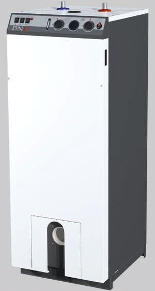
6 USER'S GUIDE INSTRUCTIONS FOR THE D-USER Essential recommendations for safety Do not store any flammable or corrosive products, paint, solvents, salts, chloride products and other detergent products near the appliance. This appliance can be used by children aged from 8 years and above and persons with reduced physical, sensory or mental capabilities or lack of experience and knowledge, only if they have been given supervision or instruction concerning use of the appliance in a safe way and understand the hazards involved. Children shall not play with the appliance. Cleaning and user maintenance shall not be made by children unless they are aged from 8 years and above and supervised. This appliance is not intended for use by persons (including children) with reduced physical, sensory or mental capabilities, unless used under the supervision of a person responsible for their safety. Children should be supervised to ensure that they do not play with the appliance. PERIODIC CHECKS Essential recommendations for the correct operation of the appliance Check regularly that the system water pressure is at least 1 bar when cold. If it is required to top up the system to maintain the minimum recommended water pressure, only add small amounts of water at a time. If a large amount of cold water is added in a hot boiler, the boiler can be damaged definitively. If the boiler safety cutout system is frequently activated, contact your installer. If the system needs to be refilled repeatedly with water, please contact your installer. Regularly check that there is no water on the floor in front of the boiler. If there is, please call your installer Key 1. ON/OFF master switch of the boiler - To turn the boiler on and off. 2. Summer-winter switch - To activate or deactivate the heating pump. 3. Energy source selector switch - To activate or deactivate the heating pump and the burner, and turn on or off a 2.4 kw heating element to meet the need in domestic hot water. 4. Heating element indicator - The built-in indicator lights when the heating element is activated. 5. DHW Thermometer - Shows the temperature of the domestic hot water. 6. Domestic hot water temperature adjustment thermostat - In DHW mode, the domestic hot water temperature can be set from 60 to 80 C. 7. Temperature and pressure gauge - Indicates the boiler temperature and the primary circuit pressure. 8. Heating temperature adjustment thermostat - Allows to set the boiler between 60 and 90 C. It is recommended to set this thermostat 10 C above the set point of the domestic hot water adjustment thermostat. 9. Pre-cut area for timer (option) - The timer allows to enable/disable the domestic hot water production according to time (24 h sequence). By pushing the white tabs located around the dial, the timer can be set (1 tab = 15 min.) for a specific operation period. 5
. Detail of components 1. Cold water inlet 2. Domestic hot water outlet 3.")
7 APPLIANCE DESCRIPTION The BNE boiler is a heat generator for central heating, with a a built-in domestic hot water preparation tank. The DHW preparation tank can operate independently from the boiler thanks to a built-in heating element (2,4 kw). Detail of components 1. Cold water inlet 2. Domestic hot water outlet 3. Manual air bleed valve 4. Control panel 5. Safety thermostat 6. Hard expanded polyurethane foam insulation 7. Stainless steel Tank in Tank hot water production tank 8. Heating circuit kw electric heating element 10. Combustion chamber 11. Turbulators (6 pieces) 12. Burner chamber plate with insulation block 13. Heating circuit outlet 14. Heating circuit inlet 15. Electrical plug of the boiler 16. A chimney connection 17. Minimum thermostat Drain valve


8 APPLIANCE DESCRIPTION
9 TECHNICAL CHARACTERISTICS ELECTRICAL CHARACTERISTICS Main electrical characteristics BNE 1 / BNE 2 Rated voltage V~ 230 Rated frequency Hz 50 Rated current with electrical heating element A 10,5 Electrical consumption with electrical heating element W 2405 IP Class IP30 Wiring diagram 1. ON/OFF master switch 2. Minimum thermostat Summer/winter switch 4. Safety thermostat 5. Oil burner 6. Heating element indicator kw electric heating element 8. Energy source selector switch 9. Room thermostat (option) 10. Heating pump of the system (optional) 11. Heating temp. adjustment thermostat 12. DHW temp. adjustment thermostat 13. Daily timer (optional) B : Blue Bk : Black Br : Brown G : Grey Or : Orange R : Red V : Violet W : White Y : Yellow Y/Gr : Yellow/Green The heating element is composed of two 2.4 kw resistances. One of the resistances is connected through a cable and used as the main heating element, while the second one is a back-up that is used in case the main one fails. Never connect both resistances simultaneously or the internal cables of the boiler will be damaged. 8
10 TECHNICAL CHARACTERISTICS B B4 PE B B N M PE S3 L1 7 G 1 2 C D t 2 R Y V? 9 t 3?? Or W t Or Or Bk 1 t 11 t 2 4? 8? Or? Br Br B Y/Gr Or B Y/Gr Or Y/Gr Br Y/Gr Y/Gr B Or Or Or G R W G R B B B Br B Y/Gr Y/Gr L1 N PE Y/Gr Y/Gr 9
11 TECHNICAL CHARACTERISTICS DIMSIONS Boiler Dimensions BNE 1 BNE 2 A = Width mm B = Height mm C = Depth mm D mm E mm F mm Volume of the combustion chamber dm³ Height mm Combustion chamber Width mm Depth mm Drained weight Kg A 280 mm 270 mm B D 260 mm 130 mm E F C 10
12 TECHNICAL CHARACTERISTICS Boiler Clearance BNE 1 / BNE 2 Recommended Minimum A (mm) B (mm) C (mm) D (mm) E (mm) C 700 D B A E 11
13 TECHNICAL CHARACTERISTICS COMBUSTION CHARACTERISTICS Main Characteristics BNE 1 BNE 2 Fuel type Oil Oil Max. input (PCI) kw Output at 100% (80/60 C) kw Output power min (80/60 C) kw Max operating temperature C HYDRAULIC CHARACTERISTICS Main hydraulic characteristics BNE 1 BNE 2 Water content of the boiler L Primary circuit capacity L Heating inlet/outlet connection (F) Ø 1" 1" DHW inlet/outlet connection (M) Ø 3/4" 3/4" Max. service pressure of DHW circuit bar 7 7 Max. service pressure of heating circuit bar 3 3 Primary circuit water pressure drop ( T = 20 K) mbar DHW PERFORMANCE Operating conditions at 80 C BNE 1 BNE 2 Peak flow at 40 C [ T = 30 K] L/10' Peak flow at 40 C [ T = 30 K] L/60' Constant flow at 40 C [ T = 30 K] L/h MAXIMUM OPERATING CONDITIONS Maximum Service Pressure [DHW tank full of water] - Primary circuit :... 3 bar - DHW circuit :... 8,6 bar - Recommended safety valve (central heating) :... 3 bar - Recommended safety valve (DHW) :... 7 bar Mains supply pressure - Max 6 bar, without a pressure reducing valve being required (to avoid discharge of the safety pressure valve) Maximum Operating Conditions - Maximum temperature (central heating) : C - Maximum temperature (DHW) :... from 60 C to 80 C Water Quality See Recommendations for the Prevention of Corrosion and Scaling. Oil quality Low sulfur oil (50 ppm) Standard oil (2000 ppm) Bio-oil 0 at 7% methyl esters of fatty acids 12
14 TECHNICAL CHARACTERISTICS CHIMNEY CONNECTION CHARACTERISTICS Chimney characteristics BNE 1 / BNE 2 Connection type B23 A = Top ventilation cm B = Bottom ventilation cm C = min. of flue pipe mm 130 L = maximum length of flue pipe ( 130 mm) m 15 Max. temp of flue gases C 180 Chimney connection diagram 1 x 45 elbow 1 m straight pipe 1 x 90 elbow 1.5 m straight pipe C A L B23 B D 13

15 INSTALLATION PACKAGE CONTTS The appliance is delivered assembled, tested and packaged separately. Package : One BNE boiler. Installation, Operation and Maintenance Instructions A drain valve General remarks The manufacturer reserves the right to change the technical characteristics and features of its products without prior notice. The availability of certain models as well as their accessories may vary according to markets. TOOLS REQUIRED FOR THE INSTALLATION 14


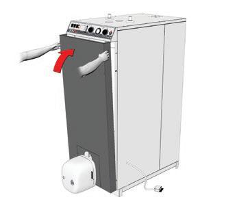
16 INSTALLATION HOW TO MOVE THE BOILER Using a hand truck Use a means of transport adapted to the boiler weight. Minimum width of the door and the hall necessary to pass the boiler C A B A = maximum boiler width B = maximum boiler length C = Door width D = Hall width Door height = std D Hall width : C = A D x B Example of calculation to determine the minimum hall width, with adoor width: D = 800 mm 540 C = x 1000 = Hall width 675 mm 800 Door width: D = A C x B Example of calculation to determine the minimum door width, with ahall width: D = 900 mm 540 D = x 1000 = Hall width 600 mm
17 INSTALLATION SAFETY INSTRUCTIONS FOR THE INSTALLATION General remarks The connections (electrical, flue pipe, hydraulic) must be carried out in accordance with current standards and regulations in force. If the water drawing off point is far from the tank, installing an auxiliary DHW loop can allow to get hot water more quickly at all times. Essential recommendations for the correct operation of the appliance The boiler must be installed in a dry and protected area. Install the appliance to ensure easy access at all times. To avoid any risk of corrosion, connect the stainless steel DHW production tank directly to the earth. Make sure to install a pressure reducing valve set at 4.5 bar if the mains supply pressure is in excess of 6 bar. The DHW circuit must be fitted with an approved safety group, comprised of a 7 bar safety valve, a check valve and a shut-off valve. If works need to be performed (in the boiler room or close to the air vents), make sure to turn off the boiler to prevent dust from entering and accumulating in the boiler heating system. Essential recommendations for safety Install the boiler on a base made of non-combustible materials. Make sure that all air vents are unobstructed at all times. A condensation outlet connected to the sewer must be fitted close to the boiler to prevent the condensation products from the flue pipe from running into the boiler. The horizontal flue pipes must be installed with a slight slope of 5 cm per meter, so that the acid condensation water flows to a condensate recovery container and does not damage the heating body. Do not store any corrosive products, paint, solvents, salts, chloride products and other detergent products near the appliance. The flue pipe diameter must not be smaller than that of the boiler flue gas outlet connection. 16
18 INSTALLATION Hot water can cause scalding! In the event of small amounts of hot water repeatedly being drawn off, a stratification effect can develop in the tank. The upper hot water layer may then reach very high temperatures. ACV recommends using a pre-set thermostatic mixing valve in order to provide hot water at a maximum of 60 C. Water heated to wash clothes, dishes and for other uses can cause serious burns. In order to avoid exposure to extremely hot water that can cause serious burns, never leave children, old people, disabled or handicapped people in the bath or shower alone. Never allow young children to turn on the hot water or fill their own bath. The temperature of the domestic hot water can be adjusted up to 90 C in the boiler. However, the temperature of the domestic hot water at the drawing off point must comply with local regulations. (E.g. in Belgium, the maximum DHW water temperature at a drawing off point must be 75 C for boilers < 70 kw). The risk of developing bacteria exists, including Legionella pneumophila, if a minimum temperature of 60 C is not maintained in both the DHW tank and the hot water distribution network. Essential recommendations for the electrical safety Only an approved installer is authorized to carry out the electrical connections. Install a 2-way switch and a fuse or circuit breaker of the recommended rating outside the appliance, so as to be able to shut power down when servicing the appliance or before performing any operation on it. Isolate the external electrical supply of the appliance before performing any operation on the electrical circuit. This appliance is not intended for use by persons (including children) with reduced physical, sensory or mental capabilities, or lack of experience and knowledge, unless supervised or unless they have been given instruction concerning the use of the appliance by a person responsible for their safety. 17
19 INSTALLATION RECOMMDATIONS FOR THE PREVTION OF CORROSION AND SCALING IN HEATING SYSTEMS How oxygen and carbonates can affect the heating system Oxygen and dissolved gasses in the water of the primary circuit contribute to the oxidation and the corrosion of the system components that are made of ordinary steel (radiators,...). The resulting sludge is then deposited in the boiler exchanger. The combination of carbonates and carbon dioxide in the water results in the formation of scale on the hot surfaces of the installation, including those of the boiler exchanger. These deposits in the heat exchanger reduce the water flow rate and thermally insulate the exchange surfaces, which is likely to damage them. Sources of oxygen and carbonates in the heating circuit The primary circuit is a closed circuit; the water it contains is therefore isolated from the mains water. When maintaining the system or filling up the circuit, water renewal results in the addition of oxygen and carbonates in the primary circuit. The larger the water volume in the system, the larger the addition. Hydraulic components without an oxygen barrier (PE pipes and connections) admit oxygen into the system. Prevention Principles 1. Clean the existing system before installing a new boiler - Before the system is filled, it must be cleaned in accordance with standard Chemical cleaning agents can be used. - If the circuit is in bad condition, or the cleaning operation was not efficient, or the volume of water in the installation is substantial (e.g. cascade system), it is recommended to separate the boiler from the heating circuit using a plate-to-plate exchanger or equivalent. In that case, it is recommended to install a hydrocyclone or magnetic filter on the installation side. 2. Limit the fill frequency - Limit fill operations. In order to check the quantity of water that has been added into the system, a water meter can be installed on the filling line of the primary circuit. - Automatic filling systems are not recommended. - If your installation requires frequent water refilling, make sure your system is free of water leaks. - Inhibitors may be used in accordance with standard Limit the presence of oxygen and sludge in the water - A deaerator (on the boiler flow line) combined with a dirt separator (upstream of the boiler) must be installed according to the manufacturer's instructions. - ACV recommends using additives that keep the oxygen in solution in the water, such as Fernox ( and Sentinel ( products. - The additives must be used in accordance with the instructions issued by the manufacturer of the water treatment product. 18
20 INSTALLATION 4. Limit the carbonate concentration in the water - The fill water must be softened if its hardness is higher than 20 fh (11,2 dh). - Check regularly the water hardness and enter the values in the service log. - Water hardness table : Water hardness fh dh mmolca(hco3)2 / l Very soft Soft Fairly hard Hard Very hard > 42 > 23.5 > Control the water parameters - In addition to the oxygen and the water hardness, other parameters of the water must be checked. - Treat the water if the measured values are outside the range. Acidity 6,6 < ph < 8,5 Conductivity Chlorides Iron Copper < 400 μs/cm (at 25 C) < 125 mg/l < 0,5 mg/l < 0,1 mg/l 19
21 INSTALLATION BOILER PREPARATION
22 INSTALLATION ELECTRICAL CONNECTIONS Description 1. Room thermostat 2. Heating pump of the system 3. Bridge (to be removed before connecting the room thermostat) L1 T1 T2 S3 B4 N 1 t 2 M 3 L1 N T1 T2 S3 B4 N PE L1 230 V ~ 50HZ B4 S3 T2 T1 N L1 21
23 INSTALLATION FLUE CONNECTION Operation related to the ambient air (Type B23 Installation) To ventilate the boiler room, it is required to install- in accordance with combustion regulations - a fresh air inlet of at least 150 cm 2 or to provide a connection with other rooms to ensure a fresh air supply. To get optimum sound comfort, it is recommended to: - install the boiler on a solid base (eg. concrete support) instead of a hollow base (eg. concrete blocks), which could create a resonance volume. - uncouple the boiler from the system hydraulic circuit by installing a hose connection on the inlet and outlet circuits and make sure that the hose connections are not taut or twisted. - increase the gas exhaust duct diameter if required (min 80 mm diameter). - uncouple the gas exhaust circuit from the flue pipe wall, adding soft insulation between the pipe and the wall, so that the vibrations from the operating boiler are not transferred to the building walls. C A L B23 B D 22
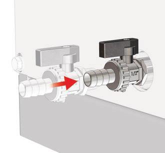
24 INSTALLATION DHW CONNECTION General remark The circuit illustrations are basic principle diagrams only. Essential recommendation for safety The hot water output may reach temperatures in excess of 60 C, which can cause scalding! It is therefore necessary to install a thermostatic mixing valve after the appliance. Essential recommendations for the correct operation of the appliance Flush the system before connecting the domestic hot water circuit. Refer to the installation instructions. Make sure to install a pressure reducing valve set at 4.5 bar if the mains supply pressure is in excess of 6 bar. The installation must be fitted with an approved safety group, comprised of a 7 bar safety valve, a check valve and a shut-off valve. Typical installation Description 1. Isolating valve 2. Pressure reducing valve 3. Check valve 4. DHW expansion vessel 5. Safety valve 6. Drain valve 7. Draw-off tap 8. Grounding 9. Thermostatic mixing valve Cold water Hot water 6 23
25 INSTALLATION HEATING CIRCUIT CONNECTION 1. Heating circuit isolating valve 2. Check valve 3. Heating pump of the system 4. Mixing valve 5. Safety group 6. Primary circuit filling valve 7. Heating circuit expansion vessel 8. Drain valve 9. Automatic air bleed valve 10. Bypass 11. Safety thermostat for floor heating circuit Do not install thermostatic valves on the radiators located in rooms fitted with a room thermostat. Heating circuit with convector Floor heating circuit t
26 INSTALLATION OIL CONNECTION General remark The oil connection must comply with all applicable standards. Essential recommendation for safety Refer to the technical characteristics and safety instructions of the burner technical manual. Failure to comply with the instructions could result in damage to the material, personal injury or death. Essential recommendations for the correct operation of the appliance Bleed the oil duct and check thoroughly if all the boiler tubes, both internal and external, are tight. Control the oil supply connection and tightness. 25
27 STARTING UP SAFETY INSTRUCTIONS FOR STARTING UP General remark In normal operation, the burner starts automatically as soon as the boiler temperature drops below the preset temperature. Essential recommendations for safety The components inside the control panel may only be accessed by an approved installer. Set the water temperature in accordance with usage and local plumbing codes. TOOLS REQUIRED FOR STARTING UP CHECKS BEFORE STARTING UP Essential recommendation for safety Check the tightness of the flue pipe connections. Essential recommendation for the correct operation of the appliance Control the tightness of the hydraulic circuit connections. 26
28 STARTING UP FILLING THE SYSTEM First put the DHW tank under pressure before pressurizing the heating (primary) circuit. Filling the domestic hot water circuit 1. Open the isolating valves (1) and the draw-off tap (2). 2. Once the water flow rate has stabilized and the air is totally evacuated from the system, close the draw-off tap (2) Check all the connections for leaks. Cold water Hot water Preliminary filling of the heating circuit Fill the primary circuit with mains water until you reach an approximate pressure of 1,5 bar in the system. Bleed the whole system. 27
29 STARTING UP STARTING UP THE BOILER Set-up conditions All connections made External power supply enabled Oil supply open DHW and heating circuits full of water Procedure 1. Put the ON/OFF master switch to ON 2. Rotate the boiler control thermostat clockwise to generate a heat demand. 3. Possibly increase the set temperature of the room thermostat, if installed. 4. Check with your hand (motor vibrations) that the heating pump of the system is not blocked and unblock it if required. Follow-on tasks Adjust the combustion,see paragraph below. COMBUSTION ADJUSTMT Set-up conditions Operating boiler Procedure 1. Refer to the starting up instructions detailed in the technical manual. of your burner 2. Adjust CO2 in a range of 13 to 14 % by setting the oil pressure as well as the shutter as described in the Starting up paragraph of the boiler (see the burner manual). 3. Check the flue temperature and CO. Follow-on tasks Bleed the heating circuit again to restore a 1.5 bar pressure. Repeat the sequence until complete evacuation of the air contained in the circuit. 28
30 MAINTANCE SAFETY INSTRUCTIONS FOR THE BOILER MAINTANCE Essential recommendation for the electrical safety Isolate the external power supply of the appliance before performing any operation, unless it is required to take measurements or perform system setup. Essential recommendations for safety Water flowing out of the drain valve may be extremely hot and could cause severe scalding. Check the tightness of the flue pipe connections. Essential recommendations for the correct operation of the appliance It is recommended to have the boiler and the burner serviced at least once a year or every 1,500 hours. More frequent servicing may be required depending on boiler use. Please consult your installer for advice. The boiler and burner maintenance will be carried out by a qualified engineer, and the defective parts may only be replaced by genuine factory parts. Control the tightness of the hydraulic circuit connections. Make sure to replace the gaskets of the removed items before reinstalling them. 29
31 MAINTANCE PERIODIC BOILER MAINTANCE TASKS Tasks 1. Make sure that the system water pressure is at least 1 bar when cold. Top up the system if necessary, adding small quantities of water at a time. In case of repeated fills, call your installer. 2. Check that there is no water on the floor in front of the boiler. Call your installer if there is. 3. Check the presence of a flame through the flame sight glass. If there is no flame, see the burner manual. 4. Check that the heating pump system is running by placing a hand on it. 5. Check the correct operation of all thermostats and safety devices: boiler thermostat, safety thermostat, safety valves, etc. 6. Check that the the oil connections are tight and there is no leak, that the hoses are not kinked and that there is not entrance of air in the circuit. 7. Check that all hydraulic and electrical connections are correctly fastened and tight. 8. Check the flue gas exhaust: correct fastening, correct installation, no leaks or clogging. 9. Check the combustion parameters (CO and CO2), see "Combustion adjustment", page Clean the burnera and the heating body, see "Cleaning the burner and the heating body", page "Cleaning the burner and the heating body", page 31 and the burner manual. Periodic inspection End-user X X X Frequency 1 year 2 years Professional X X X X X X X X X X 30
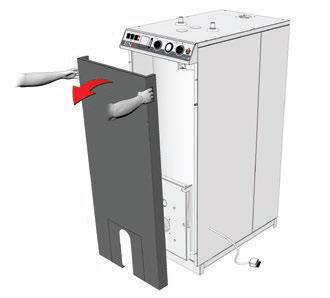
32 MAINTANCE It is recommended to stop the boiler and have it serviced during good weather conditions. CLEANING THE BURNER AND THE HEATING BODY Set-up conditions Boiler shut-down External power supply isolated Oil supply closed Procedure 1. Open the front panel. 2. Release the burner flange and place the burner in the maintenance position to clean it (see the burner manual). 3. Remove the burner 4. Open the heating body door. 5. Using a brush, clean the soot that may be present in the heating body and on the turbulators. 6. Check the correct position of the braid. Follow-on tasks Close the door and tighten with sufficient torque to ensure it is sealed against combustion products. Reinstall the burner flange and the burner. Close the front panel. 31
33 MAINTANCE DRAINING THE BOILER Before draining the DHW tank, drain the heating (primary) circuit or bring its pressure to 0 bar. Water flowing out of the drain valve may be extremely hot and could cause severe scalding. Keep people away from the hot water discharge. Set-up conditions Boiler switched off using the ON/OFF master switch External power supply isolated Fuel/gas supply closed 3 Heating circuit draining procedure 1. Close the isolating valves (1). 2. Connect the drain valve (2) to the sewer with a hose. 3. Open the drain valve (2) to empty the heating circuit of the boiler. 4. Open the circuit air bleed valve (3) to accelerate the draining process. 5. Close the drain valve (2) and the air bleed valve (3) once the heating circuit of the boiler is empty DHW circuit draining procedure Cold water Hot water Before draining the DHW tank, make sure that the heating (primary) circuit pressure is null Open fully a draw-off tap (3) for about 60 minutes to make sure that the DHW tank has cooled down. 2. Close the isolating valves (1). 3. Connect the drain valve (2) to the sewer with a hose. 4. Open the drain valve (2) and drain the DHW tank water to the sewer. 5. Open the draw-off tap (3) to accelerate the draining process. If it is located lower than the tank connection, open a draw-off tap located higher in the system. 6. Close the drain valve (2) and the draw-off tap (3) once the DHW tank of the boiler is empty. 2 32

34 MAINTANCE RESTART AFTER MAINTANCE Set-up conditions All removed components reinstalled All connections made Oil supply open DHW and heating circuits full of water Procedure 1. Energize the appliance and switch it on. 2. Set the appliance at maximum power and check the absence of burned gas leaks. 3. Check the correct operation of the charging pump. 4. Check the oil pressure and CO 2 adjustment in accordance with procedure "Combustion adjustment", page 28. IN CASE OF PROBLEM... In case of problem, please contact you ACV representative and provide the appliance part number and serial number, written on the type plate. Boiler Marking Location: at the back of the appliance. The part number (Code) and serial number (N ) of the appliance are written on the type plate and must be provided to ACV in the case of a warranty claim. If they are not provided, the warranty claim shall be void. 33
35 DECLARATION OF CONFORMITY - EC 34
36 35
37 MARKINGS LABELS 36
INSTALLATION, OPERATION AND MAINTENANCE INSTRUCTIONS
 INSTALLATION, OPERATION AND MAINTANCE INSTCTIONS BNE 2 Conds 21.8 kw 664Y5900 D TABLE OF CONTTS GERAL RECOMMDATIONS...4 USER'S GUI...5 Instructions for the d-user... 5 Periodic checks... 5 APIANCE DCRIPTION...6
Installation, operation and maintenance instructions. HRi Y1300-A
 Installation, operation and maintance instructions HRi 321-601 - 800 Table of contts Geral Recommdations...4 User's Guide...5 Control Panel... 5 Appliance Description...6 Models - HRi 321 601-800... 6
INSTALLATION, OPERATION AND MAINTENANCE INSTRUCTIONS,
 EN INSTALLATION, OPERATION AND MAINTENANCE INSTCTIONS, for the User and the Installer HR i 320-600 - 800 A1002237-661Y1300 B EN EN TABLE OF CONTENTS GENERAL RECOMMENDATIONS...3 PRODUCT INFORMATION...4
INSTALLATION, OPERATION AND MAINTENANCE INSTRUCTIONS,
 INSTALLATION, OPERATION AND MAINTENANCE INSTCTIONS, for the User and the Installer EN SMART Line SL 320-420 - 420 Duplex - 600 A002875-66Y300 A EN TABLE OF CONTENTS GENERAL RECOMMENDATIONS...4 Energy labelling...
SMART Line Smart E
 INSTALLATION, OPERATION AND MAINTENANCE INSTCTIONS, for the User and the Installer SMART Line 30-60 - 20-240 - 300 Plus 20-240 - 300 A002858-66Y200 B TABLE OF CONTENTS GENERAL RECOMMENDATIONS...4 PRODUCT
INSTALLATION, OPERATION AND MAINTENANCE INSTRUCTIONS, for the User and the Installer. SMART Line. Smart ME A Y2000 B
 INSTALLATION, OPERATION AND MAINTENANCE INSTCTIONS, for the User and the Installer SMART Line Smart ME 00-300 - 400-600 - 800 A00859-66Y000 B TABLE OF CONTENTS GENERAL RECOMMENDATIONS...4 PRODUCT INFORMATION...5
INSTALLATION, OPERATION AND MAINTENANCE INSTRUCTIONS,
 INSTALLATION, OPERATION AND MAINTENANCE INSTCTIONS, for the User and the Installer SMART GREEN 130-160 - 210 A1002064-661Y3000 B TABLE OF CONTENTS GENERAL RECOMMENDATIONS...4 PRODUCT INFORMATION...5 Energy
Installation, Operating and Servicing Instructions
 EN 0 / 0 / 00 / 800 Installation, Operating and Servicing Instructions excellence in hot water EN Y000.D EN INDEX Warnings Who should read these instructions Symbols Recommendations Applicable standards
Installation, operating and. Comfort
 EN Installation, operating and servicing instructions Comfort 00-0 - 60-20 - 20 TABLE OF CONTENTS EN GENERAL Notes Certification CE Standards Packaging SAFETY PRECAUTIONS 5 Symbols used 5 Recommdations
Installation, Operating and Servicing Instructions
 ENGLISH 0 / 0 / 0 / 0 / 00 Installation, Operating and Servicing Instructions FRANCAIS NEDERLANDS ESPAÑOL Y000.A EN ESPAÑOL NEDERLANDS FRANCAIS ENGLISH INDEX WARNING Who should read these instructions
INSTALLATION, OPERATION AND MAINTENANCE INSTRUCTIONS,
 INSTALLATION, OPERATION AND MAINTENANCE INSTCTIONS, for the User and the Installer SMART Line SL 320-420 - 420 Duplex - 600 A1004777-661Y3100 B TABLE OF CONTENTS GENERAL RECOMMENDATIONS...4 Energy labelling...
INSTALLATION, OPERATING AND SERVICING INSTRUCTIONS BG 2000-S (V13) RU PL DE IT ES NL EN 1 662Y0600 A
 RU PL DE IT ES NL EN 1 662Y0600 A") INSTALLATION, OPERATING AND SERVICING INSTRUCTIONS G 2000-S 25-35 - 45-55 60-70 - 100 (V13) 1 Index WARNINGS GAS FLOW RATE DIMSIONS SETTINGS PARAMETERS SERVICING THE URNER 3 8 13 OPERATING DESCRIPTION
INSTALLATION, OPERATING AND SERVICING INSTRUCTIONS G 2000-S 25-35 - 45-55 60-70 - 100 (V13) 1 Index WARNINGS GAS FLOW RATE DIMSIONS SETTINGS PARAMETERS SERVICING THE URNER 3 8 13 OPERATING DESCRIPTION
INSTALLATION, OPERATION AND MAINTENANCE INSTRUCTIONS
 EN INSTALLATION, OPERATION AND MAINTENANCE INSTCTIONS for the Installer and the User N - N2 - N3 eco A00570-664Y7700 B EN TABLE OF CONTENTS GENERAL RECOMMENDATIONS...3 USER S GUI...4 Meaning of Symbols...4
Installation, operating and servicing instructions
 English 57-115 - 144-1 - 259 Installation, operating and servicing instructions ITALIA EN 1 ITALIA English INDEX WARnINGS 3 Who should read these instructions 3 Symbols 3 Recommendations 3 Importants notes
INSTALLATION, OPERATION AND MAINTENANCE INSTRUCTIONS
 NSTALLATN, PERATN AND MANTANCE NSTRUCTNS HeatMaster 00 N 00 F HeatMaster 00 N / 00 F : 664Y6300 TALE F CNTTS WARNNGS 3 Who should read these nstructions 3 Symbols 3 Warnings 3 Recommendations 3 USER S
INSTALLATION, OPERATION AND MAINTENANCE INSTRUCTIONS
 NSTALLATN, PERATN AND MANTANCE NSTRUCTNS HeatMaster 30 N 60 N 70 N 100 N 1 664Y5400 TALE F CNTTS WARNNGS 3 Who should read these nstructions 3 Symbols 3 Recommendations 3 Warnings 3 NSTALLATN 14 Package
INSTALLATION, OPERATION AND MAINTENANCE INSTRUCTIONS. HeatMaster TC 664Y6800 A
 INSTALLATION, OPERATION AND MAINTENANCE INSTCTIONS HeatMaster 25-35 - 45-70 - 85-120 TC 664Y6800 A TALE OF CONTENTS GENERAL RECOMMENDATIONS...4 USER'S GUI...5 Instructions for the d user... 5 Periodic
INSTALLATION, OPERATION AND MAINTENANCE INSTRUCTIONS, for the User and the Installer. SMART Line. Smart ME A Y2000 C
 INSTALLATION, OPERATION AND MAINTANCE INSTCTIONS, for the User and the Installer SMART Line Smart ME 00-300 - 400-600 - 800 A1003499-661Y000 C TABLE OF CONTTS GERAL RECOMMDATIONS...4 PRODUCT INFORMATION...5
Remeha. Fuel oil/gas boilers P 520. Installation and Service Manual A
 Remeha Fuel oil/gas boilers EN Installation and Service Manual 300016859-001-A 63115 Declaration of conformity The appliance complies with the standard model described in declaration of compliance. It
ELECTRIC BOILERS FOR CENTRAL HEATING
 ELECTRIC BOILERS FOR CENTRAL HEATING TermoMax INSTRUCTIONS FOR INSTALLATION INSTRUCTIONS FOR INSTALLATION We reserve the right of alternations WE ARE NOT LIABLE FOR DAMAGES RESULTING FROM NON- OBSERVING
Installation, operation and care. Pellmax UB. Burner not included Replaces:
 Installation, operation and care Burner not included 2011-11-11 ver: Replaces: Contents 11.11 otes...3 General...4 Function...4 Technical data...5 System principle Pellmax with radiator and tank-in-tank
HeatMaster 25 C. Installation, operating and maintenance. excellence in hot water 664Y4500 E
 HeatMaster 25 C English Installation, operating and maintenance instructions excellence in hot water INDEX Important notes 4 ho should read these instructions 4 Symbols 4 Recommendations 4 Certification
Aqua Balance. User s Information Manual. WMB-155C Wall Mount Gas-Fired Combination Boiler Heating and Domestic Hot Water
 Aqua Balance WMB-155C Wall Mount Gas-Fired Combination Boiler Heating and Domestic Hot Water User s Information Manual * Low Lead Content If the information in this manual is not followed exactly, a fire
Operating instructions
 Operating instructions Capriz 2 24c 28c GB, IE Contents Contents 1 Safety... 3 1.1 Action-related warnings... 3 1.2 Intended use... 3 1.3 General safety information... 4 2 Notes on the documentation...
Operating instructions
 The energy you need Operating instructions Betacom 3 24c -A (H-GB) 30c -A (H-GB) GB, IE Contents Contents 1 Safety... 3 1.1 Action-related warnings... 3 1.2 Intended use... 3 1.3 General safety information...
WHE 2.24 / WHE 2.24 FF
 EN Wall-hung gas boilers WHE 2.24 WHE 2.24 FF User Guide 300011777-001-C . Contents 1 Introduction.............................................................................3 1.1 Symbols used...........................................................................................3
Installation, operating and maintenance instructions
 English Prestige50-75 - 120 MCA-5 Installation, operating and maintenance instructions EN 1 English INDEX Important notes 3 Who should read these instructions 3 Symbols 3 Recommendations 3 Certification
User s Information Manual
 User s Information Manual Gas-Fired Water Boilers With or without Aqua Logic (CWH) Now available Matching High Performance Companion Water Heater (Unit sold separately) If the information in this manual
Residential Gas Condensing Boiler Greenstar ZBR16/21/28/35/42-3A... ZWB28/35/42-3A...
 70 80 99-00-O Residential Gas Condensing Boiler ZBR//8/35/4-3A... ZWB8/35/4-3A... 70 80 993 (03/03) CA/US Operating Instructions Contents Contents Key to symbols and safety instructions............................
GB24 & GB30. User Manual
 GB24 & GB30 User Manual BOILER OUTPUT To Domestic Hot Water:To Central Heating: GB24/30 Minimum 8.0 kw (27,296 Btu/h) GB24 Maximum 24.2 kw (82,570 Btu/h) GB30 Maximum 30.3 kw (103,384 Btu/h) GB24/30 Minimum
INSTALLATION, OPERATION AND MAINTENANCE INSTRUCTIONS
 INSTALLATION, OPEATION AND MAINTANCE INSTUCTIONS HeatMaster 71 101 201 1 664Y6100 TALE OF CONTTS WANINS 3 Who should read these Instructions 3 Symbols 3 ecommendations 3 Warnings 3 USE UIDE 4 Use of the
TABLE OF CONTENTS. Site preparation 2 Placement. 2 Chimney and stove pipe connections. 2
 TABLE OF CONTENTS SECTION TITLE PAGE 1. SITE PREPARATION AND INSTALLATION Site preparation 2 Placement. 2 Chimney and stove pipe connections. 2 Installation. 3 Water supply and return.. 3 Pressure/relief
STORAGE WATER HEATERS
 Owners Manual STORAG WATR HATRS RBC 200, RBC 300, RBC 400, RBC 500, RBC 500HP, RBC 750, RBC 1000, RBC 1000HP, RBC 1500, RBC 2000, RBC 3000 N v. 1.4 CONTNTS 1 Description... 3 1.1 Models... 3 1.2 Tank protection...
INSTALLATION, OPERATION AND MAINTENANCE. Ariterm Vedo
 INSTALLATION, OPERATION AND MAINTENANCE Ariterm Vedo CONTENTS General...3 Installation...4-5 Laddomat 21 Connection diagram...6 Temperature control valve...7 About burning wood...8 Operation...9-11 Service
TECHNICAL MANUAL ASGX
 TECHNICAL MANUAL ASGX MEDIUM/HIGH PRESSURE HOT WATER BOILER INDEX 1 TECHNICAL CHARACTERISTICS... 2 1.1 GENERAL... 2 1.2 TECHNICAL DATA... 2 2 ACCESSORIES... 3 2.1 PRESSURE... 3 Pressure gauge... 3 Operation
SIME FORMAT WALL HUNG BOILERS MODEL 34i AND MODEL 34e. cod A
 cod. 6272262A GENERAL DATA Heating Data Heat Output Input (Adjustable) (Adjustable) Format 34i 11.2 34KW 45 145MJ/hr Format 34e 11.2 34KW 45 145MJ/hr General Specifications FORMAT 34i 34e Main burner injectors
2.1 BOILER ROOM BOILER ROOM DIMENSIONS 2.3 CONNECTING UP SYSTEM 2.4 CONNECTING UP FLUE 2.5 ELECTRICAL CONNECTION
 FONDERIE SIME S.p.A. of Via Garbo 27 - Legnago (VR) - Italy declares that its diesel-burning boilers are produced in accordance with the requirements of article 3 paragraph 3 of Directive PED 97/23/EEC
Operating instructions
 Operating instructions For the operator Operating instructions HOME SYSTEM GB, IE Publisher/manufacturer Vaillant GmbH Berghauser Str. 40 D-42859 Remscheid Tel. +49 21 91 18 0 Fax +49 21 91 18 28 10 info@vaillant.de
VIESMANN. Operating instructions VITODENS 050-W. for the system user. With constant temperature or weather-compensated control unit
 Operating instructions for the system user VIESMANN With constant temperature or weather-compensated control unit VITODENS 050-W 9/2014 Please keep safe. Safety instructions For your safety Please follow
1 VICTRIX ZEUS Superior kw I features
 Wall-hung condensing VICTRIX ZEUS Superior kw I is the new range of wall-hung condensing boilers with 54 litre stainless steel storage tank available in two versions with nominal heat output of 26 kw and
INSTALLATION AND OPERATION MANUAL
 INSTALLATION AND OPERATION MANUAL PRESSURISED STEEL BOILERS AR 30 AR 1000 RADIALAND - BOILER's INSTALLATION MANUAL version 1.0 / 15-02-2008 The company E. is outstanding in the field of central heating
O. Gas boiler. Gaz 6000 W WBN H-E-N/L-S2400. Operating instructions for the end customer (2017/09) en
 en") 8 716 473 216-00.3O Gas boiler WBN 6000-30-H-E-N/L-S2400 Operating instructions for the end customer en 2 Contents Contents 1 Key to symbols and safety instructions................... 2 1.1 Key to symbols..................................
8 716 473 216-00.3O Gas boiler WBN 6000-30-H-E-N/L-S2400 Operating instructions for the end customer en 2 Contents Contents 1 Key to symbols and safety instructions................... 2 1.1 Key to symbols..................................
User manual. Dishwasher ZDI12001
 EN User manual Dishwasher ZDI12001 Contents Safety information 2 Product description _ 3 Control panel 3 Programmes 4 Before first use _ 4 Daily use 7 Care and cleaning 9 Troubleshooting 9 Technical information
FAVORIT W0P. EN User manual
 FAVORIT 77000 W0P EN User manual 2 www.aeg.com CONTENTS 1. SAFETY INSTRUCTIONS...................................................... 3 2. PRODUCT DESCRIPTION.....................................................
Internet Version for Reference Only INDUCED DRAFT COMMERCIAL WATER HEATERS SUPPLEMENT INSTRUCTIONS TO PART #
 INDUCED DRAFT COMMERCIAL WATER HEATERS SUPPLEMENT INSTRUCTIONS TO PART #238-39387-00 THIS INSTRUCTION SUPPLEMENT IS ONLY INTENDED TO GIVE INSTALLATION INSTRUCTIONS AND INFORMATION RELATED TO THE INDUCED
VIESMANN. Service instructions VITORONDENS 200-T. for contractors. Vitorondens 200-T Type BR2A, 20.2 to 53.7 kw Oil Unit condensing boiler
 Service instructions for contractors VIESMANN Vitorondens 200-T Type BR2A, 20.2 to 53.7 kw Oil Unit condensing boiler For applicability, see the last page VITORONDENS 200-T 6/2011 Please keep safe. Safety
User s Information Manual
 User s Information Manual Gas-Fired Storage Water Heater, Tankless Water Heater, Heating Appliance, and Combination Appliance Models IF THE INFORMATION IN THIS MANUAL IS NOT FOLLOWED EXACTLY, A FIRE OR
User s Information Manual
 User s Information Manual Series 3 Models 550 and 750 MBH Commercial Condensing Gas-fired water boilers If the information in this manual is not followed exactly, a fire or explosion may result, causing
HeatMaster. Installation, operating and servicing instructions. HeatMaster 71 HeatMaster 101 HeatMaster 201 ENGLISH FRANCAIS NEDERLANDS ESPAÑOL
 HeatMaster ENGLISH Installation, operating and servicing instructions HeatMaster 71 HeatMaster 101 HeatMaster 201 664Y2500. EN 1 ENGLISH INDEX IMPORTANT NOTES 3 Who should read these instructions 3 Symbols
GAS FIRED ATMOSPHERIC ELECTRONIC VERSION kw
 GAS FIRED ATMOSPHERIC ELECTRONIC VERSION 51-102 kw GENERAL DESCRIPTION 900 D a3 1000 762 672 E 222 The PEGASUS F2 range of atmospheric natural gas-fired boilers are constructed of cast iron finned sections
User manual. Dishwasher ZDT15002
 EN User manual Dishwasher ZDT15002 Contents Safety information 2 Product description _ 3 Control panel 4 Programmes 4 Options _ 5 Before first use _ 5 Daily use 7 Care and cleaning 9 Troubleshooting 10
USER GUIDE. IMAX XTRA EL kW. For Installation Guide see reverse of book
 USER GUIDE IMAX XTRA EL 320-620kW For Installation Guide see reverse of book When replacing any part on this appliance, use only spare parts that you can be assured conform to the safety and performance
INSTALLATION AND OPERATING INSTRUCTIONS KLIMA
 INSTALLATION AND OPERATING INSTRUCTIONS KLIMA - 1 - CONTENTS 1.- PRESENTATION... 2 2.- LIST OF COMPONENTS... 3 3.- CONTROL ELEMENTS... 4 4.- INSTALLATION INSTRUCTIONS... 5 4.1 LOCATION... 5 4.2 FLUE...
/2010 US/CA
 6 720 646 148-11/2010 US/CA (en) For the user User s Instructions Condensing gas boiler Logamax plus GB162-L.B. 80 kw/100 kw Please read thoroughly before operating This manual is available in the English
Operating instructions
 Operating instructions Gas condensing boiler WARNING: If the information in this manual is not followed exactly, a fire or explosion may result causing property damage, personal injury or loss of life.
User s Information Manual
 User s Information Manual Series 2 Models 1000-2000 MBH Commercial Condensing Gas-fired water boilers If the information in this manual is not followed exactly, a fire or explosion may result, causing
VICTRIX 90 VICTRIX 115 Wall-hung condensing boilers for high power
 VICTRIX 90 VICTRIX 115 Wall-hung condensing boilers for high power VICTRIX 90 is the new wall-hung condensing boiler for room heating only, set-up for independent functioning and for that in cascade mode
ProCon Streamline Gas Condensing Boiler. Installation and Operating Manual.
 1 MHG Heating Ltd ProCon Streamline Gas Condensing Boiler. Installation and Operating Manual. Unit 4 Epsom Downs Metro Centre, Waterfield, Tadworth, Surrey, KT20 5LR Telephone 08456 448802 Fax 08456 448803
FAVORIT W0P. EN User manual
 FAVORIT 88419 W0P EN User manual 2 www.aeg.com CONTENTS 1. SAFETY INSTRUCTIONS...................................................... 3 2. PRODUCT DESCRIPTION.....................................................
User s Information Manual
 TM User s Information Manual Commercial Condensing Gas-fired water boilers If the information in this manual is not followed exactly, a fire or explosion may result, causing property damage, personal injury
DH-Direct Fired Poultry Farm Diesel Heater
 DH-Direct Fired Poultry Farm Diesel Heater Comparison of Diesel Heater to Gas Heater Diesel LPG Gas LPG Gas KW 43 70 120 Fuel consumption/hr 3 5.1 8.8 Heat output 37000 60000 100000 Cost of fuel/lit or
T UNI 7000 F. Operating instructions For the user (2006/05) AU/GB
 AU/GB") 6 720 648 662-00.1T UNI 7000 F Operating instructions For the user AU/G 2 Contents Contents Contents 2 1 Safety information and explanation of symbols 3 1.1 For your safety 3 1.2 Explanation of symbols
6 720 648 662-00.1T UNI 7000 F Operating instructions For the user AU/G 2 Contents Contents Contents 2 1 Safety information and explanation of symbols 3 1.1 For your safety 3 1.2 Explanation of symbols
FAVORIT 34502VI0. EN User manual
 FAVORIT 34502VI0 EN User manual 2 www.aeg.com CONTENTS 1. SAFETY INSTRUCTIONS...................................................... 3 2. PRODUCT DESCRIPTION.....................................................
INDIRECT WATER HEATERS
 INSTRUCTIONS INDIRECT WATER HEATERS ST-300D, ST-200D HEAT PUMPS STAINLESS STEEL INDIRECT FIRED WATER HEATERS ST-200D, ST-300D 1. Product Description Indirect fired water heaters ST-200D and ST-300D are
INSTRUCTIONS FOR USE... 2
 5095109600 Rev. 1 19-03-2012 825440 INSTRUCTIONS FOR USE... 2 De Longhi Australia Pty Ltd ABN 49 104 012 857 Po Box 4540 Casula Mall NSW 2170 Australia Phone: 1800 126 659 Fax: 1800 007 289 www.kenwood-australia.com
VIESMANN. Service instructions VITOLADENS 300-T. for contractors. Vitoladens 300-T Type VW3B Inox-Radial heat exchanger for oil fired condensing Unit
 Service instructions for contractors VIESMANN Vitoladens 300-T Type VW3B Inox-Radial heat exchanger for oil fired condensing Unit VITOLADENS 300-T 1/2007 Please keep safe. Safety instructions Safety instructions
USER S MANUAL. Heat Recovery Ventilator. Vents Brig HRV 200 Vents Brig HRV 300
 USER S MANUAL Heat Recovery Ventilator Vents Brig HRV 200 Vents Brig HRV 300 2 Brig HRV 200 (300) CONTENT Introduction... 3 Application... 3 Delivery set... 3 Unit designation key... 4 Basic unit dimensions...
INSTALLATION, OPERATION AND MAINTENANCE. Ariterm Hybrid 20
 INSTALLATION, OPERATION AND MAINTENANCE Ariterm Hybrid 20 TABLE OF CONTENTS General...3 Installation... 4-5 Dimensions - with flue gas exhauster...6 Dimensions - without flue gas exhauster...7 Pipe installations...8
Technical Datasheet. Solo Innova Models 30 and 50. Benefits at a Glance: Solo Innova
 Solo Innova Models 30 and 50 Technical Datasheet Solo Innova Solo Innova is a patented, wood-fired gasification boiler available in two sizes with outputs from 102,500 to 170,700 Btu/hr. Benefits at a
HG 675 CX 60 HG 675 CN 60 HG 675 CW 60
 HG 675 X 60 HG 675 CX 60 HG 675 CN 60 HG 675 CW 60 1 2 1. : 93/68: 90/396: 2006/95/CE: 2004/108/CE: - 1935/2004:. 2002/95/CE: RoHS 2.,.,,,,...,. (,..)..,,.,. ( ),,, ;,,.,.....,.,,,,,,...,. (..),,.,..,.,,,,
HIGH POWER. VICTRIX PRO 2 ErP. High power, wall-hung condensation boiler
 HIGH POWER VICTRIX PRO 2 ErP High power, wall-hung condensation boiler MAIN INDEX INDEX 1 VICTRIX PRO 35-55 2 ErP SPECIFICATIONS...5 2 VICTRIX PRO 80-100-120 2 ErP SPECIFICATIONS...6 3 VICTRIX PRO 35-55
Operating instructions
 Operating instructions Gas-fired condensing boiler Logano plus GB312 For the user Please read carefully before use 7 747 009 296-01/2007 EN Contents 1 For your safety..............................................
INLINE СENTRIFUGAL FAN BOX BOX-R OPERATION MANUAL
 INLINE СENTRIFUGAL FAN BOX BOX-R OPERATION MANUAL CONTENT 3 Introduction 3 General 3 Safety rules 3 Storage and transportation rules 3 Manufacturer s warranty 4 Fan design 4 Delivery set 5 Technical data
INSTALLATION, COMMISSIONING AND OPERATING MANUAL
 INSTALLATION, COMMISSIONING AND OPERATING MANUAL 1 YTBV-D-CE42_0109 CONTENT Available models and capacities Supplier information Warranty Safety Emergency stops/ shutdowns About this manual Models Physical
Cooker Hood Instruction Manual
 Cooker Hood Instruction Manual Model number(s): RHSCH601SS/B & RHSCH901SS/B IMPORTANT: RETAIN FOR FUTURE REFERENCE Contents Safety Instructions. 3-6 Product Overview. 7 Positioning. 8 Operational modes.
IST 03 C ELBA DUAL INSTALLATION, USE AND MAINTENANCE
 IST 03 C 202-01 ELBA DUAL INSTALLATION, USE AND MAINTENANCE GB Thank you for choosing our boilers. Please read these installation and maintenance instructions with care. Please note that the boiler must
Servicing manual. 600 Series - 11S / 19S / 24S / 24C. Wall-mounted condensing gas boiler. For trade use
 GB122 Servicing manual Wall-mounted condensing gas boiler 600 Series - 11S / 19S / 24S / 24C For trade use Please read thoroughly before attemting to diagnose fault 7217 4900 (03/2010) GB/IE List of contents
AGUAdens TM 100% residential condensing D.H.W. wall-mounted water heaters ( litres) AISI 316 D.H.W. WORKING PRESSURE TITANIUM CONDENSING
 AISI 316 D.H.W. WORKING PRESSURE TITANIUM CONDENSING") MADE IN ITALY residential condensing D.H.W. up to 10 bar WORKING PRESSURE AISI 316 Ti TITANIUM D.H.W. 100% CONDENSING AGUAdens TM wall-mounted water heaters (16-22 -37 litres) AGUAdensTM INSTANTANEOUS
MADE IN ITALY residential condensing D.H.W. up to 10 bar WORKING PRESSURE AISI 316 Ti TITANIUM D.H.W. 100% CONDENSING AGUAdens TM wall-mounted water heaters (16-22 -37 litres) AGUAdensTM INSTANTANEOUS
1. GENERAL SAFETY RULES
 ID180 & ID290 Indirect-Fired Diesel/Oil Construction Heaters Sure Flame Products Lethbridge, Alberta, Canada Telephone: (403)328-5353 Fax: (403)328-9956 www.sureflame.ca July 12, 2006 Service and Maintenance
Servicing manual. Wall-mounted condensing gas boiler 600 Series - 11S / 19S / 24S / 24C /2002 GB(EN) For trade use
 For trade use") GB122 7210 1300-12/2002 GB(EN) For trade use Servicing manual Wall-mounted condensing gas boiler 600 Series - 11S / 19S / 24S / 24C Please read thoroughly before attempting to diagnose fault List of contents
GB122 7210 1300-12/2002 GB(EN) For trade use Servicing manual Wall-mounted condensing gas boiler 600 Series - 11S / 19S / 24S / 24C Please read thoroughly before attempting to diagnose fault List of contents
INLINE CENTRIFUGAL FAN. Centro-M OPERATION MANUAL
 INLINE CENTRIFUGAL FAN OPERATION MANUAL www.blaubergventilatoren.de CONTENT 3 Introduction 3 General 3 Safety rules 3 Transport and storage requirements 3 Manufacturer's warranty 4 Fan design 4 Delivery
O Pro electric storage water heater
 O Pro electric storage water heater PREMIUM SERIES MAINS PRESSURE ELECTRIC STORAGE WATER HEATERS DOCUMENTATION FOR INSTALLATION AND OPERATION New Zealand INDOOR INSTALLATION ONLY MODEL 272014 MODEL 282029
USERS MANUAL FOR GAS BOILERS
 USERS MANUAL FOR GAS BOILERS PLEASE READ THE MANUAL CAREFULLY: IT CONTAINS IMPORTANT INFORMATION REGARDING SAFETY, INSTALLATION, USE AND MAINTENANCE OF THE APPLIANCE MODELS: NOVADENS 24 NOVADENS 24C NOVADENS
E-COMBI EVO E-SYSTEM EVO
 E-COMBI EVO E-SYSTEM EVO User s manual CONDENSING WALL-HUNG GAS BOILER G.C.N.:47-116-68 (24 kw) G.C.N.:47-116-69 (30 kw) G.C.N.:47-116-70 (38 kw) G.C.N.:41-116-39 (24 kw) G.C.N.:41-116-40 (30 kw) Country
Heating, Air Conditioning, Ventilation. Отопление-Кондиционеры-Вентиляция. MTM 8-30 kw UNIVERSAL OIL HEATER OPERATING MANUAL
 Heating, Air Conditioning, Ventilation Отопление-Кондиционеры-Вентиляция MTM 8-30 kw UNIVERSAL OIL HEATER OPERATING MANUAL 1. Usage MTM 8-30 universal oil heater is designed for heating commercial rooms
User s Information Manual
 Gas-fired Water boiler Series 2 NOTICE: Series 1/Series 2 identification Read the boiler rating plate to determine the series number. The rating plate is located on the right side of the boiler. User s
FAVORIT34502VIO. EN User Manual
 FAVORIT34502VIO EN User Manual 2 www.aeg.com CONTENTS 1. SAFETY INFORMATION...3 2. SAFETY INSTRUCTIONS... 4 3. PRODUCT DESCRIPTION... 6 4. CONTROL PANEL...6 5. PROGRAMMES... 7 6. SETTINGS... 8 7. BEFORE
BG2000S PRE-MIX GAS BURNER
 BG000S PRE-MIX GAS BURNER INSTALLATION OPERATION & MAINTENANCE DOCUMENTATION STOKVIS ENERGY SYSTEMS 96R WALTON ROAD EAST MOLESEY SURREY KT8 0DL TEL: 08707 707 77 FAX: 08707 707 767 E-MAIL:info@stokvisboilers.com
LIBRA DUAL INSTALLATION USE AND MAINTENANCE. Italian product. High quality IST 04 C
 LIBRA DUAL High quality Italian product GB INSTALLATION USE AND MAINTENANCE IST 04 C 220-02 Dear Customer, Thank you for choosing and buying one of our boilers. Please read these instructions carefully
INSTALLATION AND MANINTENANCE INSTRUCTIONS
 INSTALLATION AND MANINTENANCE INSTRUCTIONS Appr. Nr. A 9503 T - 0085 AQ 0765 PEGASUS F2 T HIGH EFFICIENCY GAS-FIRED CAST-IRON BOILERS Models 51-68 - 85-102 2 Contents 1. General technical data 2. Dimensional
Tankless Water Heater
 Tankless Water Heater USER S INFORMATION MANUAL Models WGRT**150 / WGRT**199 / WGRTC**199 **A suffix of LP denotes propane gas **A suffix of NG denotes natural gas NOTICE: Westinghouse reserves the right
Gas Fire Patio Heater Q9
 Gas Fire Patio Heater Q9 Instruction Manual Please read the manual BEFORE you unpack or install the fire TABLE OF CONTENTS Warning 3 Getting Started 4 What s Included 5 Assembly Procedures 6 Product Drawing
Installation and operating instructions. DK energy storage and DK energy buffer
 Installation and operating instructions DK energy storage and DK energy buffer Edition: 08-2015 1 Preliminary note With this DK energy storage / DK energy buffer you purchased a DK quality product. The
INSTRUCTION MANUAL FOR OIL BURNER MODELS
 INSTRUCTION MANUAL FOR OIL BURNER MODELS X400 Bio B10 E90-803-001-001-03 Rev 13-1 - Contents Technical specifications Technical data... 3 Working field... 3 Dimensions... 4 Head and electrode settings...
User manual. Dishwasher ZDT12041FA
 EN User manual Dishwasher ZDT12041FA Contents Safety instructions 2 Control panel 3 Programmes _ 4 Options _ 4 Before first use _ 5 Daily use _ 7 Hints and tips 9 Care and cleaning 9 Troubleshooting 10
VIESMANN. Service instructions VITOCELL 300-B VITOCELL 300-V. for contractors
 Service instructions for contractors VIESMANN Vitocell 300-B Type EVB DHW cylinder, 300 and 500 l Vitocell 300-V Type EVI DHW cylinder, 200 to 500 l For applicability, see the last page VITOCELL 300-B
SOUND-INSULATED FAN. Iso-K OPERATION MANUAL. Iso-K_v.1(2)-EN.indd :20:59
-EN.indd :20:59") SOUND-INSULATED FAN OPERATION MANUAL _v.1(2)-en.indd 1 10.08.2015 15:20:59 CONTENT Introduction 3 General 3 Safety rules 3 Transport and storage requirements 3 Manufacturer's warranty 3 Fan design 4 Delivery
SOUND-INSULATED FAN OPERATION MANUAL _v.1(2)-en.indd 1 10.08.2015 15:20:59 CONTENT Introduction 3 General 3 Safety rules 3 Transport and storage requirements 3 Manufacturer's warranty 3 Fan design 4 Delivery
Electrical Mini Tank Water Heater anual, and Warranty nformation
 Electrical Mini Tank Water Heater Installation uide, ser anual, and Warranty nformation Electrical Mini Tank Water Heater 2.6 Gals 2.6 IMPORTANT SAFETY INFORMATION A SAFETY VALVE MUST BE USED FOR PROPER
User manual. Dishwasher ZDI12010XA
 EN User manual Dishwasher ZDI12010XA Contents Safety instructions 2 Control panel 4 Programmes _ 4 Before first use _ 5 Daily use _ 7 Hints and tips 9 Care and cleaning 9 Troubleshooting 10 Technical information
INSTALLATION AND OPERATING INSTRUCTIONS BIOCLASS HM
 INSTALLATION AND OPERATING INSTRUCTIONS BIOCLASS HM Thank you for choosing a DOMUSA TEKNIK heating boiler. Within the product range offered by DOMUSA TEKNIK you have chosen BioClass HM model. With a suitable