Installation Operation Maintenance
|
|
|
- Chad Gray
- 6 years ago
- Views:
Transcription

1 Installation Operation Maintenance Airfinity Rooftop units Heat Pump sizes: IH039 - IH040 - IH049 - IH050 - IH059 - IH060 - IH064 - IH065 - IH074 - IH075 - IH084 - IH085 - IH100 - IH110 - IH130 R410A Refrigerant RT-SVX056A-GB Original instruction
2 Table of Contents General Information...4 Foreword... 4 Warnings and Cautions...4 Safety Recommendations... 4 Reception... 4 Loose Parts Inventory... 4 Warranty... 4 Refrigerant... 4 Maintenance Contract... 5 Storage... 5 Training... 5 Unit Model Number Description...6 IH General Data...8 Unit Operating Principle...12 Installation...13 Reception of Units Roof Curb Installation Installing the Unit Unit overall view Dimensions/Weights/Clearances Connection of Duct Network Condensate Drain Piping Filter Installation Supply plug fan airfl ow adjustment Supply fan Airfl ow measurement option General Electrical Recommendations Installer-Supplied Components Electrical Connections Operating Map...21 Cooling mode Heating mode Options...22 Fresh air hood and grill installation Building Pressurization Control Hot Water Coil (HWC)...24 Electric Heater Heat Recovery Module Trane RT-SVX056A-GB
3 Table of Contents Controls...29 CH536 + module extension Control Hardware Modules Service Terminal CO 2 sensor CO 2 sensor maintenance Fire Thermostat Clogged Filter Detector...30 Smoke Detector Other accessories available Alarm and Warnings...30 Customer option module...31 Customer option module Operation with a conventional themostat Economizer control Operation...33 Test Procedures Maintenance...34 End-user Routine Maintenance Service Technician Maintenance Troubleshooting Recommended service routine frequencies...35 Maintenance routine...36 Additionnal services...37 RT-SVX056A-GB 3
4 General information Foreword These instructions are given as a guide to good practice in the installation, start-up, operation, and maintenance by the user, of Trane Airfinity rooftop units. They do not contain full service procedures necessary for the continued successful operation of this equipment. The services of a qualified technician should be employed through the medium of a maintenance contract with a reputable service company. Read this manual thoroughly before unit start-up. Units are assembled, pressure tested, dehydrated, charged and tested in accordance with factory standard before shipment. Warnings and Cautions Warnings and Cautions appear at appropriate sections throughout this manual. Your personal safety and the proper operation of this machine require that you follow them carefully. The constructor assumes no liability for installations or servicing performed by unqualified personnel. WARNING! Indicates a potentially hazardous situation which, if not avoided, could result in death or serious injury. CAUTION! Indicates a potentially hazardous situation which, if not avoided, may result in minor or moderate injury. It may also be used to alert against unsafe practices or for equipment or property-damage-only accidents. Safety Recommendations To avoid death, injury, equipment or property damage, the following recommendations should be observed during maintenance and service visits: 1. The maximum allowable pressures for system leak testing on low and high pressure side are given in the chapter Installation. Insure to do note exceed test pressure by using appropriate device. 2. Disconnect the main power supply before any servicing on the unit. 3. Service work on the refrigeration system and the electrical system should be carried out only by qualified and experienced personnel. 4. To avoid any risk, it is recommended to place the unit on an area with restricted access. Reception On arrival, inspect the unit before signing the delivery note. Specify any visible damage on the delivery note, and send a registered letter of protest to the last carrier of the goods within 7 days of delivery. Notify the local TRANE sales office at the same time. The delivery note must be clearly signed and countersigned by the driver. Any concealed damage shall be notified by a registered letter of protest to the last carrier of the goods within 7 days of delivery. Notify the local TRANE sales office at the same time. Important notice: No shipping claims will be accepted by TRANE if the above mentioned procedure is not respected. For more information, refer to the general sales conditions of your local TRANE sales office. Note: Unit inspection in France. Delay to send registered letter in case of visible and concealed damage is only 72 hours. Loose Parts Inventory Check all the accessories and loose parts that are shipped with the unit against the shipping list. Included in these items will be the all kind of sensors, thermostat and electrical diagrams, service literature, which are placed inside the control panel and/or indoor section for shipment. Warranty Warranty is based on the general terms and conditions of the manufacturer. The warranty is void if the equipment is repaired or modified without the written approval of the manufacturer, if the operating limits are exceeded or if the control system or the electrical wiring is modified. Damage due to misuse, lack of maintenance or failure to comply with the manufacturer s instructions or recommendations is not covered by the warranty obligation. If the user does not conform to the rules of this manual, it may entail cancellation of warranty and liabilities by the manufacturer. Refrigerant Consult the addendum to Manuals for units with refrigerant, for conformity to the Pressure Equipment Directive (PED) 97/23/EC and Machinery Directive 2006/42/EC. 4 RT-SVX056A-GB
5 General information Maintenance Contract It is strongly recommended that you sign a maintenance contract with your local Service Agency. This contract provides regular maintenance of your installation by a specialist in our equipment. Regular maintenance ensures that any malfunction is detected and corrected in good time and minimizes the possibility that serious damage will occur. Finally, regular maintenance ensures the maximum operating life of your equipment. We would remind you that failure to respect these installation and maintenance instructions may result in immediate cancellation of the warranty. Storage Take precautions to prevent condensate formation inside the unit s electrical components and motors when: a. The unit is stored before it is installed; or, b. The unit is set on the roof curb and temporary auxiliary heat is provided in the building. Isolate all side panel service entrances and base pan openings (e.g., conduit holes, Supply Air and Return Air openings, and flue openings) to minimize ambient air from entering the unit until it is ready for start-up. Do not use the unit s heater as temporary heat without completing the start-up procedures detailed under Unit Start-Up. Units charged with refrigerant should not be stored where temperatures exceed 68 C. At least every three months, attach a gauge and manually check the pressure in the refrigerant circuit. If the refrigerant pressure is below 13 bar at 20 C (or 10 bar at 10 C), call a qualified service organization or Trane Sales Office. The Trane Company will not assume responsibility for equipment damage resulting from accumulation of condensate on the unit electrical components. Training To assist you in obtaining the best use of it and maintaining it in perfect operating condition over a long period of time, the manufacturer has at your disposal a refrigeration and air conditioning service school. The principal aim of this is to give operators and technicians a better knowledge of the equipment they are using, or that is under their charge. Emphasis is particularly given to the importance of periodic checks on the unit operating parameters as well as on preventive maintenance, which reduces the cost of owning the unit by avoiding serious and costly breakdown. RT-SVX056A-GB 5
6 Unit Model Number Description Digit 1 - Manufacturing location E = Epinal France Digit 2 - Unit Model I = Airfinity Digit 3 - Unit type C = Cooling only H = Reversible Heat pump Digit Unit Nominal Capacity 039 = 39 kw 040 = 40 kw 049 = 49 kw 050 = 50 kw 059 = 59 kw 060 = 60 kw 064 = 64 kw 065 = 65 kw 074 = 74 kw 075 = 75 kw 084 = 84 kw 085 = 85 kw 100 = 100 kw 110 = 110 kw 130 =130 kw Digit 7 - Efficiency level S = Standard efficiency H = High efficiency Digit 8 - Refrigerant A = R410A Digit 9 - Unit voltage E = 400 V - 3 Ph - 50 Hz Digit 10 - Revision A Digit 11 - Revision A Digit 12 - Auxiliary Heat X = Without W = Hot water coil E = Electric heater G = Standard gas burner M = Modulating burner Digit 17 - Gas type X = Without 1 = Propane gas 2 = Natural gas Digit 14 - Airflow configuration D = Down Flow H = Horizontal Flow Digit 15 = Available static pressure 1 = Standard External Static Pressure (250 Pa) 2 = High External Static Pressure (500Pa) Digit 16 - Operating map (cooling mode) A = Standard ambient L = Low ambient Digit 17 - Free cooling (Economizer) A = Temperature control B = Enthalpy control Digit 18 - Heat Recovery Module X = Without R = Configured for Rotary Wheel T = Thermodynamic circuit Digit 19 - Dehumidification X = Without A = Dehumidification control Digit 20 - Outdoor coil treatment B = Aluminum fins E = Epoxy aluminum fins H = Microchannel (cooling only) J = E coated microchannel (cooling only) Digit 21 - Indoor coil treatment 1 = Aluminum fins 2 = Epoxy aluminum fins Digit 22 - Filtration A = G4 (50 mm) filters B = G4 (50 mm) + F7 (100 mm) filters C = G4 (50 mm) + F9 (100 mm) filters D = F5 (50 mm) + F7 (100 mm) filters Digit 23 - Temperature Zone sensor X = Without A = Duct-mounted zone sensor B = Wall mounted zone sensor Digit 24 - Room User Interface X = Without A = Wall-mounted interface THS04 B = Conventional thermostat Digit 25 - C0 2 sensor X = Without 1 = CO 2 sensor duct-mounted 2 = CO 2 sensor wall-mounted Digit 26 - Smoke detector X = Without 1 = With Digit 27 - Airflow Measurement X = Without A= Airflow measurement and display 6 RT-SVX056A-GB
7 Unit Model Number Description Digit 28 - Dirty filter detection X= Without 1 = With Dirty filter detection Digit 29 - Network protection relay X = Phase reversal protection A = Phase reversal and asymmetry protection Digit 30 - Literature Language A = Bulgarian B = Spanish C = German D = English E = French H = Dutch J = Italian K = Finish L = Danish M = Swedish N = Turkish P = Polish R = Russian T = Czech U = Greek V = Portuguese W = Slovene Y = Romanian Z = Norwegian 1 = Slovak 2 = Croatian 3 = Hungarian Digit 37 - Compressor Starter Type X = Across the line A = Soft starter Digit 38 - Service User Interface X = Without 1 = Service terminal PGD (supplied loose) Digit 39 - Fire Thermostat X = Without 1 = With fire thermostat Digit 40/41/42/43/44/45 - Not used Digit 46 - Special design X = Standard S = Special design Digit 31 - Building Pressurization Control X = Without 1 = Barometric relief damper 2 = Exhaust Fan (ESP=70 pa) 3 = Exhaust Fan - High speed (ESP=150 Pa) 4 = Configured for Return roofcurb (ESP=250 Pa) Digit 32 - Multi directional roofcurb X = Without 1 = Configured for Return roofcurb (ESP=250 Pa) Digit 33 - External Customer Input/Output X = Without 1 = With Custom I/O Digit 34 - Multi-Rooftop Control X = Without Digit 35 - Communication interfrace X = Without 1 = ModBus communication interface 2 = LonTalk communications interface 3 = BACnet (MSTP) 4 = BACnet IP Digit 36 - Not used RT-SVX056A-GB 7
8 IH General Data IH039 IH040 IH049 IH050 IH059 IH060 IH064 IH065 Cooling Mode Net Cooling Capacity (1) kw Total Power Input (1) kw Heating Mode Net Heating Capacity (1) kw Power Input (1) kwm Electric Heater Number of capacity step Nb Capacity Steps (1) kw 12,5 / 12,5 12,5 / 12,5 12,5 / 12,5 12,5 / 12,5 12,5 / 25 12,5 / 25 12,5 / 25 12,5 / 25 Electrical Data (2) (3) Main Power Supply V/Ph/ Hz 400 / 3 / / 3 / / 3 / / 3 / / 3 / / 3 / / 3 / / 3 /50 Unit Max Amps A Unit Start Up Amps (without soft starter) A Unit Start Up Amps (with soft starter) A Maximum Short Circuit rating for 0,3 sec ka Max power cable cross section (Standard unit) mm Max power cable cross section (unit with option-heat recovery, Exhaust fan, Return fan, Auxiliary heat) mm Disconnect switch std unit Sirco 125A Sirco 125A Sirco 125A Sirco 125A Sirco 125A Sirco 125A Sirco 125A Sirco 125A Disconnect switch unit with option (heat recovery, Exhaust fan, Return Fan, Auxiliary heat) Sirco 250A Sirco 250A Sirco 250A Sirco 250A Sirco 250A Sirco 250A Sirco 250A Sirco 250A Electrical data of options (2) (3) Electric Heater A Exhaust Fan (70pa) A Exhaust Fan (150pa) A Return Roofcurb A Heat Recovery (not included current for oversized fan) A Frame Frame Frame1 Frame1 Frame1 Frame1 Frame1 Frame1 Frame1 Frame1 Compressor Number of Circuits # Number of Compressor per Circuits # Type Scroll Scroll Scroll Scroll Scroll Scroll Scroll Scroll Model ZP83KCE ZP42K5E ZP104KCE ZP54K5E ZP122KCE ZP61K5E ZP143KCE ZP72KCE TFD 522 TFD 422 TFD 455 TFD 422 TFD 455 TFD 422 TFD 455 TFD 422 Max Amps per Compressor A Locked Rotor Amps per Compressor A Oil & Refrigerant Oil quantity per compressors l Oil quantity ckt1/ckt2 l 1.8/ / / / / / / /3.5 Refrgerant load per circuit (ckt1/ckt2) kg 7.5 / / / / / / / / 8.2 Outdoor Coil Type Fins & Tubes Fins & Tubes Fins & Tubes Fins & Tubes Fins & Tubes Fins & Tubes Fins & Tubes Fins & Tubes Tube Size Inches 5/16" 5/16" 5/16" 5/16" 5/16" 5/16" 5/16" 5/16" Face Area m Rows/Fin Series #/FPF 3 / / / / / / / / 192 Number of tubes in the height Indoor Coil Type Fins & Tubes Fins & Tubes Fins & Tubes Fins & Tubes Fins & Tubes Fins & Tubes Fins & Tubes Fins & Tubes Tube Size Inches 3/8" 3/8" 3/8" 3/8" 3/8" 3/8" 3/8" 3/8" Face Area m Rows/Fin Series #/FPF 3 / / / / / / / / 168 Number of tubes in the height Drain Connection No./Size mm Hot Water Coil Type Fins&Tubes- HWC01 Fins&Tubes- HWC01 Fins&Tubes- HWC01 Fins&Tubes- HWC01 Fins&Tubes- HWC01 Fins&Tubes- HWC01 Fins&Tubes- HWC01 Fins&Tubes- HWC01 Tube Size Inches 3/8'' 3/8'' 3/8'' 3/8'' 3/8'' 3/8'' 3/8'' 3/8'' Face Area m Rows/Fin Series #/FPF 2/144 2/144 2/144 2/144 2/144 2/144 2/144 2/144 Number of tubes in the height Indoor Fan Standard Type Plug Fans Plug Fans Plug Fans Plug Fans Plug Fans Plug Fans Plug Fans Plug Fans Model K3G500PA2371 K3G450PA2371 K3G500PA2371 K3G450PA2371 K3G500PB3301 K3G450PA2371 K3G500PB3301 K3G450PA2371 Minimum Airflow m 3 /h Nominal Airflow m 3 /h Maximal Airflow m 3 /h Number # Diameter mm Drive Type EC Motors EC Motors EC Motors EC Motors EC Motors EC Motors EC Motors EC Motors Motor Power (Eurovent condition) kw Motor Max Amps per fan A Motor RPM at nominal flow rate (Eurovent condition) RPM Available Static Pressure at nominal flow rate Pa RT-SVX056A-GB
9 IH General Data IH039 IH040 IH049 IH050 IH059 IH060 IH064 IH065 Oversized Type Plug Fans Plug Fans Plug Fans Plug Fans Plug Fans Plug Fans Plug Fans Plug Fans Model K3G500PA2371 K3G450PA2371 K3G500PA2371 K3G450PA2371 K3G500PB3301 K3G450PA2371 K3G500PB3301 K3G500PA2371 Minimum Airflow m 3 /h Nominal Airflow m 3 /h Maximal Airflow m 3 /h Number # Diameter mm Drive Type EC Motors EC Motors EC Motors EC Motors EC Motors EC Motors EC Motors EC Motors Motor Power (Eurovent condition) kw Motor Max Amps per fan A Motor RPM at nominal flow rate (Eurovent condition) RPM Available Static Pressure at nominal flow rate Pa Outdoor Fan Standard Ambient Type Axial / Axial / Axial / Axial / Axial / Axial / Axial / Axial / Below / AC Below / AC Below / AC Below / AC Below / AC Below / AC Below / AC Below / AC Model A6D630AN0101 A8D800A10105 A6D630AN0101 A8D800A10105 A6D630AN0101 A8D800A10105 A6D630AN0101 A8D800A10105 Nominal Airflow m 3 /h Number of fan / ckt # Diameter mm Motor Power kw Motor Max Amps per fan A Motor RPM rpm Low Ambient Type Axial / Below / EC Axial / Below / EC Axial / Below / EC Axial / Below / EC Axial / Below / EC Axial / Below / EC Axial / Below / EC Axial / Below / EC Model A3G800AS3905 A3G800AS3905 A3G800AS3905 A3G800AS3905 A3G800AS3905 A3G800AS3905 A3G800AS3905 A3G800AS3905 Nominal Airflow m 3 /h Number # Diameter mm Motor Power kw Motor Max Amps per fan A Motor RPM rpm Physical Data for Standard Unit (4) Length mm Width mm Height mm Operating Weight (Downflow Without Auxiliary Heat) kg Shipping Weight (Downflow Without Auxiliary Heat) kg Options Extra Weight (4) Hot Water Coil kg Electric Heater kg Gas Burner kg N/A N/A N/A N/A N/A N/A N/A N/A Energy Recovery Module kg Exhaust Fan kg Return Roofcurb Down kg Return Roofcurb Horizontal kg Downflow Adjustable Roofcurb kg Multidirectional Roofcurb kg Energy Recovery Module (ERM) Air Pressure Drop Pa Minimum Airflow m 3 /h Maximum Airflow m 3 /h Exchanger Wheel Diameter mm Exhaust Air Fan Diameter mm Exhaust Air Fan Motor Power kw External Static Pressure Pa Length x Width x Height mm 1750x 1750x 1750x 1750x 1750x 1750x 1750x 1750x 1180x x x x x x x x1510 Weight kg (1) Indicative performances. For detailled performances, consult order write up ( OWU). (2) Under 400V/50Hz/3Ph. (3) Electrical & system data are indicative and subject to change without notice. Please refer to unit nameplate data. (4) Indicative data. For detailled consult lifting and handling instructions in document package shipped with the unit. RT-SVX056A-GB 9
10 IH General Data IH074 IH075 IH084 IH085 IH100 IH110 IH130 Cooling Mode Net Cooling Capacity (1) kw Total Power Input (1) kw Heating Mode Net Heating Capacity (1) kw Power Input (1) kwm Electric Heater Number of capacity step Nb Capacity Steps (1) kw 12.5 / 25 12,5 / / 25 12,5 / / 37,5 25 / 37,5 25 / 37,5 Electrical Data (2) (3) Main Power Supply V/Ph/ Hz 400 / 3 / / 3 / / 3 / / 3 / / 3 / / 3 / / 3 /50 Unit Max Amps A Unit Start Up Amps (without soft starter) A Unit Start Up Amps (with soft starter) A Maximum Short Circuit rating for 0,3 sec ka Max power cable cross section (Standard unit) mm Max power cable cross section (unit with option-heat recovery, Exhaust fan, Return fan, Auxiliary heat) mm Disconnect switch std unit Sirco 125A Sirco 125A Sirco 125A Sirco 125A Sirco 125A Sirco 160A Sirco 160A Disconnect switch unit with option (heat recovery, Exhaust fan, Return Fan, Auxiliary heat) Sirco 250A Sirco 250A Sirco 250A Sirco 250A Sirco 315A Sirco 315A Sirco 315A Electrical data of options (2) (3) Electric Heater A Exhaust Fan (70pa) A Exhaust Fan (150pa) A Return Roofcurb A Heat Recovery (not included current for oversized fan) A Frame Frame Frame2 Frame2 Frame2 Frame2 Frame3 Frame3 Frame3 Compressor Number of Circuits # Number of Compressor per Circuits # Type Scroll Scroll Scroll Scroll Scroll Scroll Scroll Model SH161-4 ZP83KCE TFD ZP91KCE TFD ZP104KCE ZP122KCE TFD ZP143KCE TFD CSHD TFD Max Amps per Compressor A Locked Rotor Amps per Compressor A Oil & Refrigerant Oil quantity per compressors l Oil quantity ckt1/ckt2 l 3.5/ / / / / / /5.0 Refrgerant load per circuit (ckt1/ckt2) kg N/A 10.9 / 10.4 N/A 11 / / / / 13.2 Outdoor Coil Type Fins & Tubes Fins & Tubes Fins & Tubes Fins & Tubes Fins & Tubes Fins & Tubes Fins & Tubes Tube Size Inches 5/16" 5/16" 5/16" 5/16" 5/16" 5/16" 5/16" Face Area m Rows/Fin Series #/FPF 3 / / / / / / / 192 Number of tubes in the height Indoor Coil Type Fins & Tubes Fins & Tubes Fins & Tubes Fins & Tubes Fins & Tubes Fins & Tubes Fins & Tubes Tube Size Inches 3/8" 3/8" 3/8" 3/8" 3/8" 3/8" 3/8" Face Area m Rows/Fin Series #/FPF 4 / / / / / / / 168 Number of tubes in the height Drain Connection No./Size mm Hot Water Coil Type Fins&Tubes- HWC02 Fins&Tubes- HWC02 Fins&Tubes- HWC02 Fins&Tubes- HWC02 Fins&Tubes- HWC02 Fins&Tubes- HWC02 Fins&Tubes- HWC02 Tube Size Inches 3/8'' 3/8'' 3/8'' 3/8'' 3/8'' 3/8'' 3/8'' Face Area m Rows/Fin Series #/FPF 2/144 2/144 2/144 2/144 2/144 2/144 2/144 Number of tubes in the height Indoor Fan Standard Type Plug Fans Plug Fans Plug Fans Plug Fans Plug Fans Plug Fans Plug Fans Model K3G500PA2371 K3G500PA2371 K3G500PA2371 K3G500PA2371 K3G500PB3301 K3G500PB3301 K3G500PB3301 Minimum Airflow m 3 /h Nominal Airflow m 3 /h Maximal Airflow m 3 /h Number # Diameter mm Drive Type EC Motors EC Motors EC Motors EC Motors EC Motors EC Motors EC Motors Motor Power (Eurovent condition) kw Motor Max Amps per fan A Motor RPM at nominal flow rate (Eurovent condition) RPM Available Static Pressure at nominal flow rate Pa RT-SVX056A-GB
11 IH General Data IH074 IH075 IH084 IH085 IH100 IH110 IH130 Oversized Type Plug Fans Plug Fans Plug Fans Plug Fans Plug Fans Plug Fans Plug Fans Model K3G500PA2371 K3G500PA2371 K3G500PB3301 K3G500PB3301 K3G500PB3301 K3G500PB3301 K3G500PB3301 Minimum Airflow m 3 /h Nominal Airflow m 3 /h Maximal Airflow m 3 /h Number # Diameter mm Drive Type EC Motors EC Motors EC Motors EC Motors EC Motors EC Motors EC Motors Motor Power (Eurovent condition) kw Motor Max Amps per fan A Motor RPM at nominal flow rate (Eurovent condition) RPM Available Static Pressure at nominal flow rate Pa Outdoor Fan Standard Ambient Type Axial / Axial / Axial / Axial / Axial / Axial / Axial / Below / AC Below / AC Below / AC Below / AC Below / AC Below / AC Below / EC Model A8D800A10105 A8D800A10105 A8D800A10105 A8D800A10105 A8D800A10105 A8D800A10105 A3G800AS3905 Nominal Airflow m 3 /h Number of fan / ckt # Diameter mm Motor Power kw Motor Max Amps per fan A Motor RPM rpm Low Ambient Type Axial / Below / EC Axial / Below / EC Axial / Below / EC Axial / Below / EC Axial / Below / EC Axial / Below / EC Axial / Below / EC Model A3G800AS3905 A3G800AS3905 A3G800AS3905 A3G800AS3905 A3G800AS3905 A3G800AS3905 A3G800AS3905 Nominal Airflow m 3 /h Number # Diameter mm Motor Power kw Motor Max Amps per fan A Motor RPM rpm Physical Data for Standard Unit (4) Length mm N/A N/A Width mm N/A N/A Height mm N/A N/A Operating Weight (Downflow Without Auxiliary Heat) kg N/A N/A Shipping Weight (Downflow Without Auxiliary Heat) kg N/A N/A Options Extra Weight (4) Hot Water Coil kg N/A 59.0 N/A Electric Heater kg N/A 26.0 N/A Gas Burner kg N/A N/A N/A N/A N/A N/A N/A Energy Recovery Module kg N/A N/A Exhaust Fan kg N/A 39.0 N/A Return Roofcurb Down kg N/A N/A Return Roofcurb Horizontal kg N/A N/A Downflow Adjustable Roofcurb kg N/A N/A Multidirectional Roofcurb kg N/A N/A Energy Recovery Module (ERM) Air Pressure Drop Pa N/A N/A Minimum Airflow m 3 /h N/A N/A Maximum Airflow m 3 /h N/A N/A Exchanger Wheel Diameter mm N/A N/A Exhaust Air Fan Diameter mm N/A N/A Exhaust Air Fan Motor Power kw N/A 3.4 N/A External Static Pressure Pa N/A N/A Length x Width x Height mm N/A 2250x 2250x 2250x 2250x 2250x N/A 1180x x x x x1835 Weight kg N/A N/A (1) Indicative performances. For detailled performances, consult order write up ( OWU). (2) Under 400V/50Hz/3Ph. (3) Electrical & system data are indicative and subject to change without notice. Please refer to unit nameplate data. (4) Indicative data. For detailled consult lifting and handling instructions in document package shipped with the unit. RT-SVX056A-GB 11

12 Unit Operating Principle Figure 1 12 RT-SVX056A-GB
 Handle the machine using a forklift, in accordance with applicable safety regulations.")
 Use a lifting beam correctly adjusted to fit the unit (recommended). The units are supplied on the truck but are not unloaded.")
13 Installation General information: The installation must conform to all local standards and regulations. Reception of Units Unit Handling The unit is supplied on wooden blocks. It is recommended to check the machine s condition upon reception. There are two ways to handle the unit: 1) Handle the machine using a forklift, in accordance with applicable safety regulations. Handling of the unit is prohibited unless forks are longer than the length of the unit (not recommended as there is a risk of damage if not done carefully). 2) Use a lifting beam correctly adjusted to fit the unit (recommended). The units are supplied on the truck but are not unloaded. A lifting lug is provided on each corner of the unit s base to facilitate handling. 4 shackles and 4 slings are required. Use a lifting beam to prevent the cables pressing too hard on top of the unit during lifting. Important: For unit to fit on the roof curb the wooden blocks must be removed. Lifting and moving Instructions Specific lifting method is recommended as follows: 1 - The units are supplied with four lifting points 2 - Slings and spreader bar to be provided by rigger and attached to the four lifting points. 3 - Minimum rated lifting capacity (vertical) of each sling and spreader bar shall be no less than the unit shipping weight. 4 - Caution: The unit must be lifted with the utmost care. Avoid shock load by lifting slowly and evenly. 5 - Remove slings and spreader bars when installation is completed. The detailled handling, lifting instructions including all weights and sling lengths are given on the specific drawings and instructions shipped with the unit. Roof Curb Installation Roof curbs are available as an accessory for downflow units to support the unit and ensure the water tightness between the rooftop and the roof. Four types of roofcurbs are available: the standard version to allow the installation of the unit on a flat roof with different return flow patterns (return roofcurb down, return roofcurb horizontal, multidirectional roofcurb) and the adjustable version for a slope roof installation (adjustable roofcurb down). The roofcurb characteristic is given in roofcurb submitalls drawings sent with the unit. Figure 2 - Roofcurb down Figure 3 - Roofcurb multidirectionnal assembly RT-SVX056A-GB 13
14 Installation Instructions for the roofcurb assembly and installation with curb dimensions are provided with each roofcurb kit. In order to insure watertighness of the roofcurb assembly, it is important to respect the schematics below and to consult the booklet for roofcurb assembly shipped with the roofcurb module. Be sure that gasket is positionned on the roofcurb and without damage before unit positionning. To avoid any property damage or personal injury, it is the installer s reponsibility to make sure that the installation will not impair the function of this curb, or the unit to be installed; and that the roofcurb and unit must be completly sealed, preventing any water or air leakage damage. Figure 4 - Waterproofing 3 1. Roofcurb 2. Roof membrane 3. Seal 4. Rooftop Installing the Unit The structure accommodating the unit(s) must be designed to support the equipment in operation, as a minimum. Refer to submittals drawings supplied with the unit for dimensions, weigth and clearance requirement around unit. Unit support Install the unit on a flat foundation strong enough to support unit loading and level (within 5 mm across the length and width of the unit).if the unit is to be roof mounted check the building codes for weight distribution requirements Location and clearances Choose a location that will enable air to circulate freely in the condenser coil and allow air to be discharged above the fans. The clearance distances for air circulation and maintenance are indicated in the submittals drawings. Placing and rigging The rooftop units are designed to be installed outdoor and must be positioned horizontally (vertical air discharge off the condenser). Slab mount For ground level installation, the unit base should be adequately supported and hold the unit near level. In areas where snowfall is common, the unit must be elevated enough to ensure that the bottom of the outdoor coil is above the height of the expected snow accumulation. Where severely cold temperatures are a consideration, elevation of the unit is again recommended to ensure that defrost water does not create an ice build up that will interfere with unit operation. In addition, runoff water from roofs, etc... must not be allowed to fall on the outdoor coil; any blockage of airflow through the coil can be detrimental to unit operation and reliability. The manufacturer suggests that the bottom of the outdoor coil be raised 30cm above grade or roof to prevent possible ice build-up problems. The unit frame structure is not designed to be supported by four points (mounting on spring isolators for instance). The unit must therefore rest on its whole base. 14 RT-SVX056A-GB


15 Installation Unit overall view Figure 5 - Indoor section Embedded control solutions Trane controller with embedded energy saving functionalities. Centralized control panel for easy access and service. Remote service terminal provided as an option. EC Plug Fan Compact, quiet and more efficient compared to traditional axial fans. Rail system for easy access and maintenance. Double skin panel Double wall and thick glass wool insulation provided as standard with all units, for higher indoor air quality. Sloped drain pan Non-corrosive sloped drain for improved condensate management, thus preventing formation of microbial agents that lead to poor air quality. Figure 6 - Outdoor section High efficiency scroll compressors in tandem Delivers high performance in part load thanks to capacity modulation. Capable of meeting future EcoDesign regulations, with SEER up to 3.5. Easy handling Lifting holes designed to avoid damaging of the unit during transportation. Unit s robust structure also minimizes the need for packaging, reducing onsite waste after installation. Quick adapt Airfinity units are ideal for replacement jobs thanks to their compatibility with multiple roofcurbs (Trane and non-trane) Epoxy coating High quality Epoxy coating on fin & tube heat exchanger prevents corrosion and extends unit lifetime Fresh air hood Foldable for easy transportation and installation High Quality Air Filtration Two rails for wide range of filtration up to F9, capable of meeting local regulations Economizer with intelligent control Provided as standard with the every Airfinity unit, the economizer permits free cooling when conditions are favorable, saving up to 20% on annual energy consumption. Dual refrigeration circuit On top of improving capacity modulation and increasing part load efficiency, having two circuits also maximizes reliability by providing system redundancy Electronic Expansion Valve (EEV) Thanks to its tight control and ability to operate at a lower condensing pressure, the EEV creates additional opportunities for energy savings. Easy-access panels Can be removed easily using a common turn-key (no screws!). Prevents corrosion and missing components after service. RT-SVX056A-GB 15
16 Installation Dimensions/Weights and Clearance This information is supplied in the document package shipped with the unit. Connection of Duct Network Supply and return openings have curb flanges provided for easy duct installation. It is recommended to insulate the circumference of the curb after the unit is mounted to prevent condensation. CAUTION! All ductwork must be run and attached to the curb flanges before the unit is set into place. Guidelines for ductwork construction - Connections to the unit should be made with 7.5cm canvas connectors to minimize noise and vibration transmission. - Elbows with turning vanes or splitters recommended to minimize air noise and resistance. - The first elbow in the ductwork leaving the unit should be no closer than 60cm from the unit, to minimize noise and resistance. Figure 7 - Supplied trap Attaching horizontal ductwork to unit - All conditioned air ductwork should be insulated to minimize heating and cooling duct losses. Use minimum of 5cm of insulation with a vapor barrier. The outside ductwork must be weather proofed between the unit and the building. - When attaching ductwork to a horizontal unit, provide a flexible watertight connection to prevent noise transmission from the unit to the ducts. The flexible connection must be indoors and made out of heavy canvas. Note: Do not draw the canvas taut between the solid ducts. Condensate Drain Piping Each unit is equipped with a 1 1/4 female drainage connector. A P trap is supplied and must be connected to the drainage as shown in Figure 5. Slope the drainage pipe down at least 1% to ensure an adequate condensate flow. Check all the condensate drainage pipe fittings comply with the applicable construction regulations and waste disposal standards Panel enclosure 2. Atmosphere pressure 3. Static drain RT-SVX056A-GB
17 Installation Filter installation Access to the filter cells is done via the filter access door. Filter support can be slided laterally. Each unit is shipped with this available filter combination: G4 G4+F7 G4+F9 F5+F7 F7+F9 combination is not allowed Figure 9 - Hot water coil Pressure Drop Pressure Pa Hot Water Coil Pressure Drop Sizes 039_065 Sizes The number and the size of the filter cells are determined by the frame of the unit. Each unit has 2 rails of filter per rail Figure 10 - Electrical heater coil Pressure Drop Airflow m3/h Frame 1: 6 filters of 500x625 Frame 2: 8 filters of 500x625 Frame 3: 12 filters of 500x500 Pressure Pa Electrical heater Pressure Drop There is 3 different types of filters which are place on rails of 50 mm or 100 mm upstream of the indoor coil Figure 8 - Filter Pressure Drop 300 Clean Filter Pressure Drop Sizes 039_065 Sizes Aiflow m3/h Pressure drop [Pa] G4-Frame1 G4-Frame 2 G4-Frame 3 G4+F7-Frame1 G4+F7-Frame2 G4+F7-Frame3 G4+F9-Frame1 G4+F9-Frame2 G4+F9-Frame Airflow [m³/h] Recommended clog filter switch delta pressure value is 200 Pa with a maximum of 250 Pa according to available static pressure. RT-SVX056A-GB 17
18 Installation Supply plug fan airflow adjustment 1) Order write up (OWU) indicate design airflow, supply and design air pressure drop. 2) Verify on site supply fan airflow. It should match OWU design airflow. 3) If on site airflow is different from OWU design airflow the actual supply and design air pressure drop should be different from design values, Trane service technician should be mandated to perform air flow adjustement and optimization. According to the option chosen, airflow or fan RPM can be read directly on the optional display or should be determined by connecting a pressure drop meter to the pre mounted T connector. Setup is -20%/+30% variation versus factory setting (190m Pa). Supply fan Airflow measurement option The airflow measurement option when selected is associated with an air differential pressure sensor which measures the pressure difference before the inlet nozzle and inside the inlet nozzle. Unit air flow can be calculated on the basis of the differential pressure (difference in pressure of the static pressures) in keeping with the following equation: Qv in [m 3 /h] and p in [Pa] N number of fans k takes into account the specific nozzle characteristics. Connection on the unit side is acomplished via a premounted T tube connector. This tube connector is suited for pneumatic hoses with an internal diameter of 4 mm. k factors: Fan diameter k-factor RT-SVX056A-GB
19 Installation General Electrical Recommendations Electrical Parts When reviewing this manual keep in mind. - All field-installed wiring must be in accordance with local regulations, CE directives and guidelines. Be sure to satisfy proper equipment grounding requirements according CE - The following standardized values - Maximum Amps - Short Circuit Amps - Starting Amps are displayed on unit nameplate. - All field-installed wiring must be checked for proper terminations, and for possible shorts or grounds. Note: always refer to wiring diagrams shipped with unit or unit submittal for specific electrical schematic and connection information. WARNING Hazardous Voltage! Disconnect all electric power, including remote disconnects before servicing. Follow proper lockout/ tagout procedures to ensure the power can not be inadvertently energized. Failure to disconnect power before servicing could result in death or serious injury. Important! Do not allow conduit to interfere with other components, structural members or equipment. Control voltage (230 V) wiring in conduit must be separate from conduit carrying low voltage (<30V) wiring. To prevent control malfunctions, do not run low voltage wiring (<30V) in conduit with conductors carrying more than 30 volts. CAUTION! Inverters are equipped with integrated filters. They are not compatible with insulated neutral load earthing arrangements. WARNING! High voltage! Any contact with electric components, even after the unit has been switched off, can cause serious injury or death. Wait at least 5 minutes after switching off the unit, until the current dissipates. Grounding Be sure to ground the unit and differential protection should be suited for industrial machinery with current leak which can be higher than 300 ma (several motors and frequency drives). CAUTION! To avoid corrosion, overheating or general damage, at terminal connections of power supply wiring, unit is designed for copper mono-conductors only. In case of multiconductor cable, an intermediate connection box must be added. For cable with alternative material, bi-material connecting devices are mandatory. Cable routing inside control panel should be made case by case by installer. WARNING Ground Wire! All field-installed wiring must be completed by qualified personnel. All field-installed wiring must comply with local codes and regulations. Failure to follow this instruction could result in death or serious injury. All power supply wiring must be sized and selected accordingly by the project engineer in accordance with local codes and regulations. WARNING! The Warning Label which is displayed on the equipment and shown on wiring diagrams and schematics. Strict adherence to these warnings must be observed. Failure to do so may result in personal injury or death. CAUTION! Units must not be linked to the neutral wiring of the installation. Units are compatible with the following neutral operating conditions: TNS IT TNC TT Standard** Special Special Standard* * Differential protection should be suited for industrial machinery with current leak which can be higher than 300 ma (several motors and frequency drives). Neutral wire not distributed. ** Neutral wire not distributed Installer-Supplied Components Customer wiring interface connections are shown in the electrical schematics and connection diagrams that are shipped with the unit. The installer must provide the following components if not ordered ith the unit: Power supply wiring (in conduit) for all field-wired connections. All control (interconnecting) wiring (in conduit) for field supplied devices. Circuit breakers. RT-SVX056A-GB 19
20 Installation Electrical Connections The electric panel is located on the length of the indoor section behind the plug fan section. The unit is designed to run with 400V (+/-10%) - 50 Hz (+/-1%) - 3 ph. 2 glands are available on each unit to be able to connect the unit to the main supply either from the side or from the bottom. CAUTION! After completion of wiring, check all electrical connections, and ensure all connections are tight. Replace and secure all electrical box covers and access doors before leaving unit or connecting power to circuit supplying unit. Scroll compressors Proper phasing of the electrical power wiring is critical for proper operation and reliability of the scroll compressor and fans. Proper rotation of the scroll compressor must be established before the unit is started. This is accomplished by confirming that the electrical phase sequence of the power supply is correct. The motor is internally connected for clockwise rotation with the inlet power supply phased A, B, C. The direction of rotation may be reversed by interchanging any two of the line wires. It is this possible interchange of wiring that makes a phase sequence indicator necessary if the operator is to quickly determine the phase rotation of the compressor motor. The ABC indicator on the face of the phase indicator will glow if phase is ABC for terminals L1, L2, and L3. 20 RT-SVX056A-GB
21 Operating Map Cooling mode Ambient temperature ( C) Operating map at cooling mode Operating map of cooling mode Standard ambient Low ambient Return air mix temperature ( C) Low ambient Maximum Outdoor Temperature (@ Eurovent) = 46 C Minimum Outdoor Temperature = -5 C Maximum Indoor Coil Entering Temperature = 35 C Minimum indoor Coil Entering Temperature = 18 C Heating mode Operating map at heating mode Operating map of heating mode Ambient temperature ( C) Return air mix temperature ( C) Maximum Outdoor Temperature (@ Eurovent) = 20 C Minimum Outdoor Temperature = -15 C Maximum Indoor Coil Entering Temperature = 27 C Minimum indoor Coil Entering Temperature = 5 C RT-SVX056A-GB 21


22 Options Free cooling economizer unit is supplied with economizer and fresh air hood as a standard feature. Fresh air percentage can vary from 0 to 100%. An economizer consists of: A motorized damper with separate fresh air and return air sections. A fresh air hood with a grill delivered folded in the unit. All necessary sensors for free cooling operation. The mechanical opening of the damper is managed by the actuator which is adjusted by Trane controller. Damper is activated in free cooling mode and may be further controlled by temperature control with return and outdoor air sensors or by enthalpy control with addtion to temperature sensor of return and outdoor humidity sensor. Fresh air hood installation Figure 11 - Fresh air hood assembly steps Step 1 Step 2: Position side flange with corner on the outside Building Pressurization Control Barometric Relief The barometric relief allows to minimize overpressure in the building caused by the introduction of fresh air. This option is typically installed when fresh air intake is below 25% of the nominal air flow and when the return air pressure drop is below 25Pa. Barometric damper is integrated as standard into economizer option on downflow and not compatible with heat recovery module unit only. When the pressure of the building increase, the dampers open and relieve air to the outside. If the return air duct pressure drop is higher than the building overpressure, the dampers will not open. If the return air duct pressure drop is lower than the building overpressure, the dampers will open and relieve air outside of the building. Figure 12 - Barometric relief Step 3: lift up the hood vertically to insert it Step 4 22 RT-SVX056A-GB


23 Options Exhaust Fans The exhaust axial fans are used to minimize the overpressure in the building caused by the introduction of fresh air. This option is typically used when the fresh air intake needed is between 40 to 50% of the nominal air flow or when the return air duct pressure drop is higher than 25Pa (<70Pa or 150Pa according to option selected). This option includes hoods, gravity dampers and axial fans. Optional service Terminal allow to adjust exhaust fans start and stop value according to fresh air damper position. When the supply air fan is ON, the exhaust fans turn on whenever the position of the fresh air dampers meet or exceed the exhaust fan set point. (If the potentiometer is set at 40%, the exhaust fans will start when the fresh air dampers will meet or exceed 40% opening). Operation When the exhaust fans are OFF : - The barometric dampers open when the air pressure inside the building increases. As the building pressure increases, the pressure in the unit return section also increases, opening the dampers and relieving the air. - If return air pressure drop>building overpressure ( P>Pb Patm) barometric damper is closed. - If return air pressure drop<building overpressure ( P< Pb Patm) barometric damper opens and a maximum of 25% of the nominal airflow can be exhausted. When the exhaust fans turn ON : - Around 50% of airflow can be exhausted, depending on the pressure drop in the return air duct. - The two fans work always together, on stage ON-OFF. - Each fan has two speeds, which makes 2 configurable speeds by changing the wiring on site. - The exhaust fan is started when fresh air dampers meet or exceed a preset percentage of fresh air. Configured for Return roofcurb (ESP=250 PA) Configured for Return roofcurb (ESP=250 PA) 2 types of return roofcurbs modules have been developped (downflow and horizontal flow) in order to minimize overpressure in the buildng caused by the introduction of fresh air when there is a significant pressure drop in the return duct (250 Pa maximum) and when supply fan is not enough to overcome both supply and return external static pressure. The module is fully controlled and powered by the rooftop control. The assembly detail is given in the submitall shipped with the document package sent with the unit. Figure 14 - Return roofcurb downflow Figure 15 - Return roofcurb horizontal flow Figure 13 - Exhaust fan RT-SVX056A-GB 23


.")


24 Options Hot Water Coil (HWC) Figure 16 - Hot water coil location in the unit Water connections dimensions and characteristics Figure 17 - Hot water coil view and connections Water inlet/outlet connection 1 1/2 ISO 228/1 The hot water coil is factory mounted and placed in the discharge section. Two holes are provided to connect the hot water coil. The tubes for entering and leaving water are equipped with a threaded female connection. Figure 18 HWC applies when addtional heat is required. Hot water comes from external boiler or other device. HWC provides heating with a coil located after the indoir coil and offer full modulation heating control through the use of a 3 ways valve. Control is based on mixed air temperature and zone temperature. Factory setting is given to heat pump operation. Hot water is called in addition. Priority can be switched on site. Antifreeze protection opens the 3 ways valve when the coil temperature is closed to the freezing point (2 C). In antifreeze mode, unit operating, indoor fan is stopped and unit locked out in manual reset. Fresh air damper is closed and the modulating valves open. The freeze protection works with manual reset. Important notice: it is important that the pump circulating hot water is permanently working to avoid water to freeze in the coil. Otherwise, in order to prevent water from freezing in the coil during unoccupied period or shutdown limited period, it is recommended to use ethylene glycol. The services of a water treatment specialist are recommended if water used can cause scaling deposits or erosion. Insulate and proceed to heater wire installation on all the water piping likely to be exposed to freezing temperatures in order to avoid freeze up of the coil and heat losses. The water distribution network must be fitted with vents in places where air is likely to be trapped. Pa Hot Water Coil Pressure Drop m3/h Electric Heater HW1 Electric heaters are fitted on the supply fan discharge. Heaters have two heating stages and provided with two types of overheat thermostats: Automatic reset thermostats which stop the electric heater when the air temperature rises to 65 C. Automatic reset at 32 C. The manual reset thermostat which stops the unit when the air temperature rises to 128 C. Figure 19 - Heater onto unit and heater detail HW2 Table 1 - Ethylene glycol percentage Ethylene glycol percentage Freezing point (%) ( C) RT-SVX056A-GB


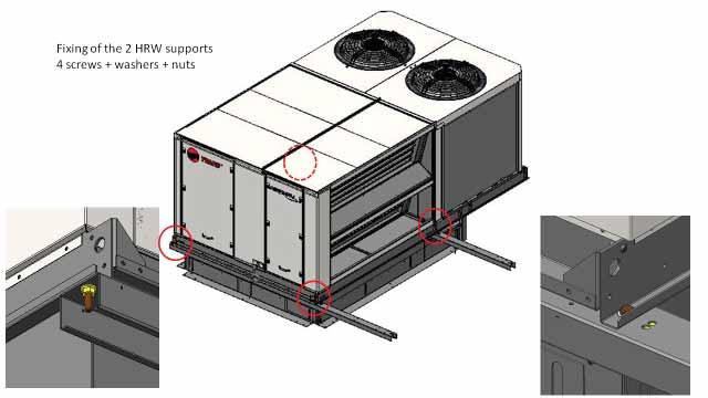
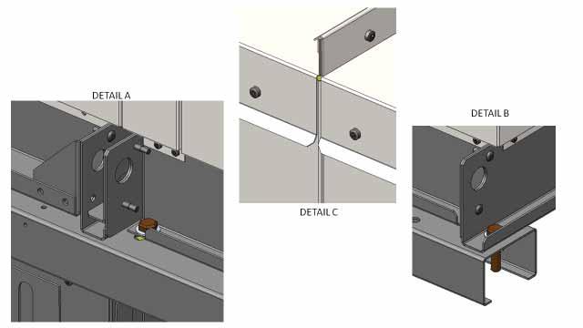
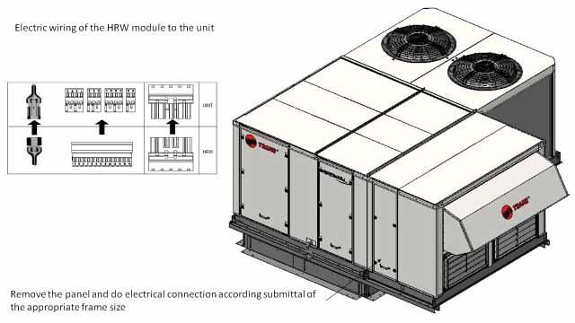
25 Options Heat Recovery Module Figure 20 Energy Recovery Module is a module that transfers heat (cool or warm) from exhaust air to fresh air. It is an addon module that includes a heat exchanger, exhaust fan, filters and dampers, heat exchanger: rotary wheel. The module is shipped separately and connected to the rooftop on jobsite The module is fully controlled and powered by the rooftop itself. Free cooling mode is still available. Assembly of the module should be done according to the below instructions and with the help of submitalls and electrical drawings shipped with the unit. Figure 21 RT-SVX056A-GB 25


26 Options Figure 22 Figure 23 Figure RT-SVX056A-GB


27 Options Figure 25 Figure 26 Figure 27 RT-SVX056A-GB 27


28 Options Figure 28 Figure 29 Figure RT-SVX056A-GB


, airflow,")
29 Controls CH536 + module extension Control Hardware Modules The main CH536 module allows the control of the heat pump, the indoor EC fan and the outdoor fan. 3 extension module can be used : - 1 module for auxiliary heat, economizer enthalpy, exhaust fan and for ERP. - 1 module for heat recovery. - 1 extension module to manage customer options. Figure 31 - CH536 main module Service Terminal The service terminal is an option to the customer, easily plugged to unit through cable. The controller is composed of six different buttons and a graphical display. This view of plug-and-play service and the controller allows personal service to read and modify some parameters of the device as setpoints (cooling and heating), airflow, alarm and warning display. It includes scrolling menus and explanation of full text. Figure 33 - Optional display Alarm Up Prog Enter Esc Down Control Hardware Bus This diagram is for information. For details refer to wiring diagram shipped with the unit. Figure 32 - Control Hardware Bus RT-SVX056A-GB 29
Installation Operation Maintenance
 Installation Operation Maintenance Airfinity Rooftop units Models IC - Cooling only IH - Heat pump 40-135 kw R410A Refrigerant RT-SVX056B-GB Original instructions Table of Contents General Information...4
Installation Operation Maintenance
 Installation Operation Maintenance Series R Air-Cooled Helical Rotary Liquid Chiller RTAD 085-180 (50Hz) Standard, Free Cooling and Heat Recovery models RTAD-SVX01F-E4 General information Foreword These
Installation Operation Maintenance
 Installation Operation Maintenance Voyager I Rooftop Units Cooling-only TSD/TSH 060 072 102 120 Reversible WSD/WSH 060 072 090 Gas-fired YSD/YSH 060 072 090 102 120 RT-SVX20D-E4 Original instruction Table
Installation Operation Maintenance
 Installation Operation Maintenance RTAF SE/HE/XE/HSS/HSE Air-cooled Helical-rotary chillers 300-1600 kw Sintesis chillers are part of the Ingersoll Rand EcoWise portfolio of products that are designed
Installation Operation Maintenance
 Installation Operation Maintenance / 015-060 Air-cooled scroll chillers and heat pumps 43-164 kw CG-SVX027B-GB Original instructions Table of Contents General Information...4 Model Number Description...6
Installation Operation Maintenance. Ductable water unit FWD FWD-SVX01D-E4
 Installation Operation Maintenance Ductable water unit FWD 08-12 - 20-30 - 45 General Information Foreword These installation, operation and maintenance instructions are given as a guide to good practice
Installation Operation Maintenance
 Installation Operation Maintenance RTAF SE/HE/XE/HSS/HSE R134a, R513A, R1234ze Air-cooled Helical-rotary chillers 300-1900 kw Sintesis chillers are part of the Ingersoll Rand EcoWise portfolio of products
Installation Operation Maintenance
 Installation Operation Maintenance DUCTABLE WATER UNIT FWD 08-12 - 20-30 - 45 General Information Foreword These installation, operation and maintenance instructions are given as a guide to good practice
SPECIFICATION GUIDE FLEXAIR. Possibility to add auxiliary heaters: Gas, Electrical Heater, Hot Water Coil Possibility to add Heat Recovery Module
 SPECIFICATION GUIDE FLEXAIR Air-cooled packaged Rooftop unit Cooling only or Heat Pump Nominal cooling capacity: 85 to 234 kw Nominal heating capacity: 83 to 226 kw Possibility to add auxiliary heaters:
Installation Operation Maintenance
 Installation Operation Maintenance CGAF Air-cooled Scroll Chillers 260-670 kw CG-SVX039A-GB Original instructions Table of Contents Introduction...3 Unit Model Number Description...4 General Data...6 Table
Submittal Data PERFORMANCE DATA CERTIFIED DIMENSION PRINTS CERTIFIED ROOF CURB DIMENSION PRINTS SERVICE OPTION DIMENSION PRINTS
 AutoZone R Model Single Package Rooftop Gas Heating/Electric Cooling Unit Size 07 with Puronr (R---410A) Refrigerant Submittal Data PERFORMANCE DATA CERTIFIED DIMENSION PRINTS CERTIFIED ROOF CURB DIMENSION
ACTIVA SERIES ROOF TOP Air Conditioners 017/040
 ACTIVA SERIES ROOF TOP Air Conditioners 017/040 Installation manual Ref.: N-40388_EN 0112 Index Index 1 Installation manual...1 1.1 Safety instructions...2 1.2 Icons used in this document...2 1.3 Instructions
Standard and CELDEK Evaporative Cooler Modules Installation, Operation, and Maintenance Manual
 Standard and CELDEK Evaporative Cooler Modules Installation, Operation, and Maintenance Manual Standard Evaporative Cooler CELDEK Evaporative Cooler RECEIVING AND INSPECTION Upon receiving unit, check
Installation Operation Maintenance
 Installation Operation Maintenance RTAF SE/HE/XE/HSE Air-cooled Helical-rotary chillers 300-750kW RLC-SVX19A-E4 Table of Contents Introduction...4 Unit Model Number Description...6 General Data...8 Operating
Submittal Data DESCRIPTION STANDARD FEATURES. Base Unit. Cabinet. Refrigerant System. Gas Heat
 SINGLE PACKAGE ROOFTOP, GAS HEATING/ELECTRIC COOLING UNIT WITH PURON R (R-410A) REFRIGERANT ONE STAGE COOLING CAPACITY CONTROL: SIZES 08-12 TWO STAGE COOLING CAPACITY CONTROL: SIZES 08, 12 & 14 Submittal
SECTION PACKAGED ROOFTOP AIR CONDITIONING UNITS
 SECTION 15732 - PACKAGED ROOFTOP AIR CONDITIONING UNITS PART 1 - GENERAL 1.1 SECTION INCLUDES A. Package roof top unit. B. Heat exchanger. C. Refrigeration components. D. Unit operating controls. E. Roof
Submittal Data PERFORMANCE DATA CERTIFIED DIMENSION PRINTS CERTIFIED ROOF CURB DIMENSION PRINTS SERVICE OPTION DIMENSION PRINTS
 Single Package Rooftop, High---Efficiency Heat Pump Units With Field---Installed Electric Heat Sizes 08 --- 14 with Puron R (R---410A) Refrigerant Submittal Data PERFORMANCE DATA CERTIFIED DIMENSION PRINTS
Standard and CELDEK Evaporative Cooler Modules Installation, Operation, and Maintenance Manual
 Standard and CELDEK Evaporative Cooler Modules Installation, Operation, and Maintenance Manual Standard Evaporative Cooler CELDEK Evaporative Cooler RECEIVING AND INSPECTION Upon receiving unit, check
Packaged Heat Pump. 20 Ton Rooftop Units with ReliaTel TM Controls NOTICE
 Service Facts Customer Property: Contains wiring and service information. Please retain. WC*240-SF-1H Library Service Literature Product Section Unitary Product Package Air Conditioner Model WC* Literature
Installation Owner Diagnostics
 Installation Owner Diagnostics Split System Cooling Condensers Model CTA 7 1/2 to 15 Tons Models A and later Design Sequence CTA 090A***A 60 HZ 120A***A 60 HZ 120B***A 60 HZ 180B***A 60 HZ SS-SVN11A-EN
kw. Flexair. General description. Main components. CLIMATIC controller. Air cooled rooftop packaged unit
 Flexair ir cooled rooftop packaged unit 85 0 kw Main applications Large and light commercial buildings inemas, theatres Industrial buildings and logistic centers Why this choice? Energy efficient solution
CELDEK Evaporative Cooler Module Installation, Operation, and Maintenance Manual. CELDEK Evaporative Cooler
 CELDEK Evaporative Cooler Module Installation, Operation, and Maintenance Manual CELDEK Evaporative Cooler RECEIVING AND INSPECTION Upon receiving unit, check for any interior and exterior damage, and
Flexy II Product catalogue
 2008/09 Flexy II Product catalogue Providing indoor climate comfort Flexy 85 234 kw Rooftop unit Introduction to the range opeland SROLL compressors for maximum efficiency, reliability and low noise Thermostatic
Submittal Data PERFORMANCE DATA CERTIFIED DIMENSION PRINTS CERTIFIED ROOF CURB DIMENSION PRINTS SERVICE OPTION DIMENSION PRINTS
 Single Package Rooftop Gas Heating/Electric Cooling Unit Two Stage Cooling Capacity Control with NOVATIONt Coil Sizes 08, 12, 14 with Puronr (R---410A) Refrigerant Submittal Data PERFORMANCE DATA CERTIFIED
Installation Operation Maintenance
 Installation Operation Maintenance Indoor liquid chiller with integrated hydraulic module Water-cooled: CGWN 205-206 - 207-208 - 209-210 - 211-212 -213-214 - 215 Condenserless: CCUN 205-206 - 207-208 -
Installation Instructions
 50ES--A, 50EZ--A, 50VG--A, B, 50VL--A, B, 50VR--A, 50VT--A, B 604D-- --A, 607C-- --A, B, 607E-- --A, 704D-- --A, 707C-- --A, B, 707E-- --A PA3G -- -- A, PH3G -- -- A, PA4G, PH4G PAD3, PHD3, PAD4, PHD4,
Installation Instructions
 50ES---A, 50EZ---A, 50VL---A, 50VG---A, 50VR---A, 50VT---A, 604D--- ---A, 607C--- ---A, 607E,--- ---A, 704D--- ---A, 707C--- ---A, 707E--- ---A PA3G --- --- A, PH3G --- --- A SMALL PACKAGED PRODUCTS Electric
Submittal Data PERFORMANCE DATA CERTIFIED DIMENSION PRINTS CERTIFIED ROOF CURB DIMENSION PRINTS SERVICE OPTION DIMENSION PRINTS
 Single Package Rooftop Gas Heating/Electric Cooling Unit Two Stage Cooling Capacity Control with Puronr (R---410A) Refrigerant Sizes: 17, 20, 24, 28, 30 Submittal Data PERFORMANCE DATA CERTIFIED DIMENSION
AQUASTYLUS Chilled Water Fan Coil Convertible Type CFEA Series 50/60 Hz
 Installation Manual AQUASTYLUS Chilled Water Fan Coil Convertible Type CFEA Series 50/60 Hz 50 Hz Models Cooling Only CFEA 04 C0M1 CFEA 06 C0M1 CFEA 08 C0M1 CFEA 10 C0M1 CFEA 12 C0M1 CFEA 14 C0M1 CFEA
Installation Instructions
 EHNA Electric Heaters 5-20kW For 60 Hz Small Packaged Products MODELS: PAD3, PHD3, PAD4, PHD4, PAD5, PHD5, WPA3, WPH3 Installation Instructions NOTE: Read the entire instruction manual before starting
LGH/LCH WARNING. CAUTION Danger of sharp metallic edges. Can cause injury. Take care when servicing unit to avoid accidental contact with sharp edges.
 Service Literature The LGH/LCH high and standard efficiency 5, 0, 5 and 50 ton (, 0.7, 58. and 75.9 kw) units, are configure to order units (CTO) with a wide selection of factory installed options. The
Installation Instructions
 Installation Instructions PAM3 SERIES PACKAGE AIR CONDITIONERS TABLE OF CONTENTS SAFETY LABELING AND SIGNAL WORDS... 2 UNIT DIMENSIONS... 3 SAFE INSTALLATION REQUIREMENTS... 3 LOCATING THE UNIT... 3 CLEARANCES...
Voyager III Rooftop Units. Voyager III. Rooftop Units RT-PRC022-E4. Cooling-only. Heat-pump. Gas-fired. Heat pump with gas-fired heating
 Voyager III Voyager III Rooftop Units Rooftop Units Cooling-only TKD/TKH 275-300-350-400-500-600 Heat-pump WKD/WKH 400-500-600 Gas-fired YKD/YKH 275-300-350-400-500-600 Heat pump with gas-fired heating
air systems Large Rooftop DIC-BIH-DIG 360 to 480 G
 Large Rooftop DIC-BIH-DIG 360 to 480 G Large Rooftop DIC-BIH-DIG A complete range from 119.1 kw up to 155.6 kw R407C Features Adjustable roof curb types YKlon 33 board Duct work configuration side or down
MODELS B1PA024, 030 AND 036
 STELLAR 2000 SINGLE PACKAGE HEAT PUMPS INSTALLATION INSTRUCTION Supersedes: 511.26-N1Y (892) 511.26-N1Y (893) MODELS B1PA024, 030 AND 036 035-11622 GENERAL YORK Model B1PA units are factory assembled heat
P8SE Series. 14 SEER, Single Phase Packaged Air Conditioner TECHNICAL SPECIFICATIONS. FEATURES and BENEFITS. 3, 4, 5 Ton Units
 TECHNICAL SPECIFICATIONS P8SE Series 14 SEER, Single Phase Packaged Air Conditioner 3, 4, 5 Ton Units The P8 Series single packaged air conditioners are high efficiency self contained cooling units that
Split System, 18,000-48,000 Btu/h Underceiling Type MCC Series 50 Hz
 Split System, 18,000-48,000 Btu/h Underceiling Type MCC Series 50 Hz Models Cooling Only MCC 518 ZB MCC 524 ZB MCC 530 ZB MCC 536 ZB MCC 048 ZB October 2007 General Information General Information Congratulations
FALCON Rooftop Units ACPSE 50/60Hz Cooling Capacity : 36 to 1388 MBH (11 to 407 kw) Heating Capacity : 40 to 1298 MBH (12 to 380 kw)
 Heating Capacity : 40 to 1298 MBH (12 to 380 kw)") FALCON Rooftop Units ACPSE 50/60Hz Cooling : 36 to 1388 MBH (11 to 407 ) Heating : 40 to 1298 MBH (12 to 380 ) R Products that perform...by people who care NOMENCLATURE 6 AC P S E 435 P - HP G Q 6-60 Hz
FALCON Rooftop Units ACPSE 50/60Hz Cooling : 36 to 1388 MBH (11 to 407 ) Heating : 40 to 1298 MBH (12 to 380 ) R Products that perform...by people who care NOMENCLATURE 6 AC P S E 435 P - HP G Q 6-60 Hz
Installation Operation Maintenance
 Installation Operation Maintenance RAUL Air Cooled Condensing Unit Sizes 190 260 300 350 400 450 500 600 700 800 To be used with the CH530 control module manual General information Foreword These instructions
INSTALLATION INSTRUCTIONS
 INSTALLATION INSTRUCTIONS 13CHPX SERIES UNITS PACKAGED HEAT PUMPS (2 5 TONS) 505,136M (38152A071) 12/09 Supersedes 05/09 Litho U.S.A. RETAIN THESE INSTRUCTIONS FOR FUTURE REFERENCE WARNING Improper installation,
INSTALLATION INSTRUCTIONS
 2011 Lennox Industries Inc. Dallas, Texas, USA INSTALLATION INSTRUCTIONS 13HPP UNITS PACKAGED HEAT PUMP UNIT (2 5 TONS) 506750 01 06/11 Supersedes 03/11 Litho U.S.A. RETAIN THESE INSTRUCTIONS FOR FUTURE
Installation Instructions
 50ZPB, C, 50ZHB, C, PA3Z ---A, PH3Z ---A, PA4Z, PH4Z, PAJ4,PHJ4,WJA4,WJH4 SMALL PACKAGED PRODUCTS (SPP) Accessory Electric Heaters 5---20 kw For 14 SEER, R---410A Manufactured Home Installation Instructions
Rooftop Units 60HZ. PACKAGED HEAT PUMPS 13HPP / rhp13 PRODUCT SPECIFICATIONS 13 HPP 36 A P - 1 A RHP 13 A 36 T - 1 A MODEL NUMBER IDENTIFICATION
 PRODUCT SPECIFICATIONS PACKAGED HEAT PUMPS 3HPP / rhp3 Rooftop Units 60HZ Bulletin No. 0634 October 04 Supersedes October 0 MODEL NUMBER IDENTIFICATION -PHASE MODELS Nominal SEER (3HPP Shown) Unit Type
Verde GSE PCA Bridge and Ground Mount Units 30/45/60/90/120 Tons. Installation and Maintenance Manual
 Verde GSE PCA Bridge and Ground Mount Units 30/45/60/90/120 Tons Installation and Maintenance Manual Rev. 09/17/2016 Table of Contents SAFETY... 3 GENERAL DESCRIPTION... 4 MOVING AND STORAGE... 4 INITIAL
BHW INSTALLATION, OPERATION AND MAINTENANCE MANUAL MEDIUM STATIC PRESSURE DUCTABLE TYPE. Models:
 INSTALLATION, OPERATION AND MAINTENANCE MANUAL BHW MEDIUM STATIC PRESSURE DUCTABLE TYPE Models: 174 205 358 410 515 720 724 Cooling capacities from 3,1 to 25 KW Heating capacities from 4,5 to 55,5 KW Thank
BRT C/H Series PACKAGED AIR TO AIR UNITS COOLING / HEATING APPLICATIONS OUTDOOR INSTALLATION. Ver. 1.01
 b cool manufacturers of air-conditioning equipment ltd BRT C/H Series PACKAGED AIR TO AIR UNITS COOLING / HEATING APPLICATIONS OUTDOOR INSTALLATION Ver. 1.01 Ver. 3.02 01_18 BCool# 1 brt c/h r407c / r410a
48PGD/E/F/L/M/N PG20-28
 48/50PG-10SB 48PGD/E/F/L/M/N20-28 50PG20-28 SINGLE-PACKAGE COOLING UNITS WITH FACTORY-INSTALLED GAS HEAT SINGLE-PACKAGE COOLING UNITS WITH OPTIONAL ELECTRIC HEAT PERFORMANCE DATA CERTIFIED DIMENSION PRINTS
THE WALL-MOUNT ONE TON AIR CONDITIONER. Green Refrigerant. 12,000 Btuh EER Right Side Control Panel. Engineered Features
 THE WALL-MOUNT ONE TON AIR CONDITIONER W2AAA 2,000 Btuh.00 EER Right Side Control Panel 60Hz Green Refrigerant R-4A The Bard Wall-Mount One Ton Air Conditioner is a self contained energy efficient heating
RV Products Division INSTALLATION INSTRUCTIONS FOR SERIES PACKAGE AIR CONDITIONER
 RV Products Division INSTALLATION INSTRUCTIONS FOR 46413 SERIES PACKAGE AIR CONDITIONER 1. WARNINGS IMPORTANT NOTICE These instructions are for the use of qualified individuals specially trained and experienced
USER'S MANUAL/INSTALLATION INSTRUCTIONS
 TM USER'S MANUAL/INSTALLATION INSTRUCTIONS P Series Single Package Convertible Air Conditioner Single Package Convertible Air Conditioner IMPORTANT These instructions are primarily intended to assist qualifi
Voyager II Rooftop Units
 Voyager II Rooftop Units Cooling-only TKD-TKH 155-175-200-250-265-290-340 Heat pump WKD-WKH 125-155-200-265-290-340 Cooling-only with gas-fired heating YKD-YKH 155-175-200-250 Heat pump with gas-fired
Weathermaster Series 48HJ004, 005, 006, 007, 008, 009, 012 & 014 COMBINATION GAS HEATING/ ELECTRIC COOLING UNITS
 48HJ-13SB Weathermaster Series 48HJ004, 005, 006, 007, 008, 009, 012 & 014 COMBINATION GAS HEATING/ ELECTRIC COOLING UNITS PERFORMANCE DATA CERTIFIED DIMENSION PRINT CERTIFIED ROOF CURB DIMENSION PRINT
AHU INSTALLATION & OPERATION MANUAL
 AHU INSTALLATION & OPERATION MANUAL VERSION 2 AIR HANDLING UNIT MODELS: AHU 500, AHU 900, AHU 1200, AHU 1700, AHU 2000, AHU 2500, AHU3500, AHU 4500, AHU 5000, AHU 6000, AHU 7000, AHU 8000, AHU 10000, AHU
RGE 13 A T - 1 A
 PRODUCT SPECIFICATIONS PACKAGED GAS / ELECTRIC 3GEP / RGE3 Rooftop Units 60HZ Bulletin No. 2063 December 202 Supersedes October 202 MODEL NUMBER IDENTIFICATION -PHASE MODELS SEER - 3.00 (3GEP Shown) AFUE
SPECTRACOOL Air Conditioner. N21 Model INSTRUCTION MANUAL nvent Rev. G P/N
 SPECTRACOOL Air Conditioner N21 Model INSTRUCTION MANUAL Rev. G P/N 89115088 TABLE OF CONTENTS WARRANTY AND RETURN POLICY...2 RECEIVING THE AIR CONDITIONER...3 HANDLING AND TESTING THE AIR CONDITIONER...3
WMHP Series R410a Heat Pump INSTALLATION INSTRUCTIONS
 WMHP Series R410a Heat Pump INSTALLATION INSTRUCTIONS **WARNING TO INSTALLER, SERVICE PERSONNEL AND OWNER** Altering the product or replacing parts with non authorized factory parts voids all warranty
Y_C-SVE002B-EN. Wiring Manual. Packaged Gas/Electric with ReliaTel Controls 3-10 Tons. Models: (60 Hz) YSC036A*R - YSC120A*R YHC033A*R - YHC120A*R
 YSC036A*R - YSC120A*R YHC033A*R - YHC120A*R") Y_C-SVE002B-EN Wiring Manual Packaged Gas/Electric with ReliaTel Controls 3-10 Tons Models: (60 Hz) YSC036A*R - YSC120A*R YHC033A*R - YHC120A*R November 2004 Introduction Literature Change History Y_C-SVE-002A-EN
Y_C-SVE002B-EN Wiring Manual Packaged Gas/Electric with ReliaTel Controls 3-10 Tons Models: (60 Hz) YSC036A*R - YSC120A*R YHC033A*R - YHC120A*R November 2004 Introduction Literature Change History Y_C-SVE-002A-EN
Installer's Guide. WARNING: HAZARDOUS VOLTAGE - DISCONNECT POWER and DISCHARGE YCC-IG EB23D1-12
 Installer's Guide YCC-IG-12 18-EB23D1-12 Single Packaged Gas/Electric 13 SEER Convertible, 1½ - 5 Ton, 40-120 MBTU R-410A ALL phases of this installation must comply with NATIONAL, STATE AND LOCAL CODES
Options Guide. Sintesis air-cooled scroll chillers Models CGAF kw
 Options Guide Sintesis air-cooled scroll chillers Models CGAF 300 700 kw AUGUST 2017 CG-PRC049A-GB Digit 1,2,3,4 Unit model CGAF = Air-Cooled Scroll Packaged Chiller Digit 5, 6, 7 - Unit Nominal Tonnage
Duct Heaters volts/1 phase volts/3 phase volts/3 phases volts/3 phases. Flange Type Duct Heater.
 Duct Heaters Synheat duct heaters come in various sizes and dimensions to fit any compartment. There are three types of duct heaters available: open coil, tubular element or finned tubular heating elements
T-SERIES Air Conditioner. T20 Model INSTRUCTION MANUAL nvent Rev. C P/N
 T-SERIES Air Conditioner T20 Model INSTRUCTION MANUAL Rev. C P/N 89114993 TABLE OF CONTENTS Warranty and Return Policy... 2 IMPORTANT NOTICE... 2 RECEIVING THE AIR CONDITIONER... 3 HANDLING AND TESTING
Installation, Start-Up and Service Instructions
 38AH044-134 Air-Cooled Condensing Units 50/60 Hz Installation, Start-Up and Service Instructions CONTENTS Page SAFETY CONSIDERATIONS...................... 1 INSTALLATION................................
INSTALLATION INSTRUCTIONS
 INSTALLATION INSTRUCTIONS R -410A Single Package Electric Cooling RAS072-150 Three Phase, 50 Hz. These instructions must be read and understood completely before attempting installation Safety Labeling
Voyager III Rooftop Units
 Voyager III Rooftop Units Cooling-only TKD/TKH 275-300-350-400-500-600 Heat-pump WKD/WKH 400-500-600 Gas-fired YKD/YKH 275-300-350-400-500-600 Heat-pump with gas-fired heating DKD/DKH 400-500-600 R410A
Service Step by Step Trouble-Shooting Check-List
 WARNING: Only Data Aire trained technician or experience technicians should be working on Data Aire Equipment. Protect yourself at all times and work safe. Date: Dates at the job site: From: to Job#: Serial#:
Advance Release September 2009
 Vertical Air Cooled DSV Series R 410A Model DSV096 DSV120 DSV144 DSV180 Nominal Cooling (Tons) 8 10 12 15 Refrigerant R 410A R 410A R 410A R 410A Cooling Performance Gross Cooling Capacity(Btu/h) 95,000*
T-SERIES Air Conditioner. T29 Model INSTRUCTION MANUAL nvent Rev. I P/N
 T-SERIES Air Conditioner T29 Model INSTRUCTION MANUAL Rev. I P/N 89104464 TABLE OF CONTENTS Warranty and Return Policy...2 IMPORTANT NOTICE...2 RECEIVING THE AIR CONDITIONER...3 HANDLING AND TESTING THE
30GH Air-Cooled Liquid Chillers 30GH Nominal cooling capacity kw
 Air-Cooled Liquid Chillers Nominal cooling capacity 21-94 kw Carrier is participating in the Eurovent Certification Programme. Products are as listed in the Eurovent Directory of Certified Products. The
Fig. 1 - Unit PGD4, PGS4, WPG4
 OWNER S MANUAL 14 SEER Single -Package Air Conditioner and Gas Furnace System with R -410A Refrigerant Single Phase 2 to 5 Nominal Tons Three Phase 3 to 5 Nominal Tons PGD4andPGS4SeriesE,WPG4SeriesB Fig.
SECTION ROTARY-SCREW WATER CHILLERS
 PART 1 GENERAL 1.01 SECTION INCLUDES A. Factory-assembled packaged chiller. B. Charge of refrigerant and oil. C. Controls and control connections. D. Chilled water connections. E. Electrical power connections.
CMA CONDENSING UNITS FOR OUTDOOR INSTALLATION INSTALLATION AND OPERATION MANUAL
 CMA CONDENSING UNITS FOR OUTDOOR INSTALLATION ECO-FRIENDLY REFRIGERANT GAS INSTALLATION AND OPERATION MANUAL Dear Customer, Thank you for having purchased a FERROLI product. It is the result of many years
Installation Instructions
 Electric Heaters 5 --- 20 kw SMALL PACKAGED PRODUCTS (SPP) Accessory Electric Heaters For 13 SEER, R---410A Manufactured Home Installation Instructions NOTE: The Dual Point Kit can only be installed on
Packaged Cooling 20 Ton Rooftop Units with ReliaTel Controls, 50 Hz
 Service Facts Packaged Cooling 20 Ton Rooftop Units with ReliaTel Controls, 50 Hz Models: TC*200FD YC*200FD SAFETY WARNING Only qualified personnel should install and service the equipment. The installation,
Owner s Information Manual
 50EZ---A and 50VT ---A Comfort and Performance 13 and 14 SEER Single Packaged Heat Pump System With PuronR (R ---410A) Refrigerant Single and Three Phase 2---5 Nominal Tons (Sizes 24---60) Owner s Information
T-Series Air Conditioner T20 Model
 INSTRUCTION MANUAL T-Series Air Conditioner T20 Model Protecting Electronics. Exceeding Expectations. McLean Cooling Technology 11611 Business Park Blvd N Champlin, MN 55316 USA Tel 763-323-8200 Fax 763-576-3200
Fig. 1 - Unit PHD4 and WPH4
 OWNER S MANUAL 14 SEER Single -Package Heat Pump System with R -410A Refrigerant Single Phase and Three Phase 2 to 5 Nominal Tons PHD4 Series F and WPH4 Series B Fig. 1 - Unit PHD4 and WPH4 A09034 NOTE
Installer s Guide CRS-2500 Single Packaged Two Stage Indirect-Direct Evaporative Cooler 2500 CFM (4250 CMH)
") Installer s Guide CRS-2500 Single Packaged Two Stage Indirect-Direct Evaporative Cooler 2500 CFM (4250 CMH) ALL phases of this installation must comply with NATIONAL, STATE AND LOCAL CODES Important This
Installer s Guide CRS-2500 Single Packaged Two Stage Indirect-Direct Evaporative Cooler 2500 CFM (4250 CMH) ALL phases of this installation must comply with NATIONAL, STATE AND LOCAL CODES Important This
DCC Series. Submittal Data Form. 7½- to 12½-Ton Three-Phase Packaged Air Conditioners
 DCC Series Submittal Data Form Job Name Purchaser Order No. Engineer Unit No. Model No. Unit Designation Performance Data Certified By: 7½- to 12½-Ton Three-Phase Packaged Air Conditioners Up to 11.3 EER
Installation Operation Maintenance
 Installation Operation Maintenance CGCL Air Cooled Water Chiller With Centrifugal Fans Sizes 200-250 - 300-350 - 400-450 - 500-600 To be used with the manual of SMM Module Reference L80IM022E CGCL-SVX01A-E4
INSTALLATION INSTRUCTIONS
 INSTALLATION INSTRUCTIONS T CLASS TSA Series 6 to 20 Ton AIR CONDITIONERS 6 20 TONS 506147 01 06/11 Supersedes 3/11 Litho U.S.A. RETAIN THESE INSTRUCTIONS FOR FUTURE REFERENCE IMPORTANT The Clean Air Act
SPECIFICATION GUIDE NEOSYS. Air-cooled Liquid Chiller for outdoor installation (NAC) Nominal cooling capacity: 200 to 460 kw
 Nominal cooling capacity: 200 to 460 kw") SPECIFICATION GUIDE NEOSYS Air-cooled Liquid Chiller for outdoor installation (NAC) Nominal cooling capacity: 200 to 460 kw Air-to-water Heat Pump for outdoor installation (NAH) Nominal cooling capacity:
SPECIFICATION GUIDE NEOSYS Air-cooled Liquid Chiller for outdoor installation (NAC) Nominal cooling capacity: 200 to 460 kw Air-to-water Heat Pump for outdoor installation (NAH) Nominal cooling capacity:
CHGV AIR COOLED WATER CHILLER WITH HYDRAULIC EQUIPMENT AIR / WATER 47 to 78 kw
 TECHNICAL INSTRUCTIONS CHGV AIR COOLED WATER CHILLER WITH HYDRAULIC EQUIPMENT AIR / WATER 47 to 78 kw CHGV CHGV 64 CHGV 72 CHGV 80 PHRV heat pump model also available May 2006 10 12 167 - GB - 00 MARKING
Options for Diesel Fire Pump Controllers
 Options for Diesel Fire Pump Controllers 2015-2016 This document describes our standard options. Please consult factory for any additional options / features / modifications if required. Modifications
MODEL HS115-3, HS115-4 & HS115-5 WIRING DIAGRAM ADDENDUM
 TJERNLUND PRODUCTS, INC. 1601 Ninth Street White Bear Lake, MN 55110-6794 PHONE (800) 255-4208 (651) 426-2993 FAX (651) 426-9547 Visit our web site www.tjernlund.com MODEL HS115-3, HS115-4 & HS115-5 WIRING
GREEN REFRIGERANT R-410A
 WALL-MOUNT HEAT PUMPS - (0HZ) Models: JH to J0H 0Hz Heating Capacities:,000 to,000 Capacities:,00 to,000 Solair Wall-Mount Heat Pump is a self-contained energy efficient heating and cooling system, which
RHGN-H: COMMERCIAL AIR HANDLER WITH VARIABLE FREQUENCY DRIVE (VFD) NOMINAL 10 TONS R-410A REFRIGERANT 2-STAGE AIR-FLOW
 NOMINAL 10 TONS R-410A REFRIGERANT 2-STAGE AIR-FLOW") INSTALLATION INSTRUCTIONS RHGN-H: COMMERCIAL AIR HANDLER WITH VARIABLE FREQUENCY DRIVE (VFD) NOMINAL 10 TONS R-410A REFRIGERANT 2-STAGE AIR-FLOW 92-106595-01-00 TABLE OF CONTENTS Introduction.......................................
INSTALLATION INSTRUCTIONS RHGN-H: COMMERCIAL AIR HANDLER WITH VARIABLE FREQUENCY DRIVE (VFD) NOMINAL 10 TONS R-410A REFRIGERANT 2-STAGE AIR-FLOW 92-106595-01-00 TABLE OF CONTENTS Introduction.......................................
CROWN. Boiler Co. Santa-Fe Series. Hydronic Air Handlers INSTALLATION, OPERATION & MAINTENANCE INSTRUCTIONS
 CROWN Boiler Co Santa-Fe Series Hydronic Air Handlers INSTALLATION, OPERATION & MAINTENANCE INSTRUCTIONS These instructions must be affixed on or adjacent to the air handler Models: SAC049A20 SAC059A25
Installation, Start-Up and Service Instructions
 38AH044-134 Air-Cooled Condensing Units 50/60 Hz Installation, Start-Up and Service Instructions CONTENTS Page SAFETY CONSIDERATIONS...................... 1 INSTALLATION................................
THE WALL-MOUNT ONE TON AIR CONDITIONER GREEN REFRIGERANT R-410A. 10,800 Btuh 9.00 EER Right Side Control Panel. Engineered Features
 THE WALL-MOUNT ONE TON AIR CONDITIONER W2A,800 Btuh 9.00 EER Right Side Control Panel 60Hz GREEN REFRIGERANT R-A The Bard Wall-Mount One Ton Air Conditioner is a self contained energy efficient heating
INSTALLATION INSTRUCTIONS
 INSTALLATION INSTRUCTIONS FOR AQUECOIL HYDRONIC HEATING UNITS GENERAL INFORMATION The AQUECOIL Hydronic Heating Unit is offered in many different capacities and physical configurations in order to match
TECHNICAL SPECIFICATIONS
 TM TECHNICAL SPECIFICATIONS Model PPH1SD Series M1200 Product Line Single Packaged Heat Pump 13 SEER - 3, 4 and 5 Ton Units M1200 12 YEAR ALL PARTS LIMITED WARRANTY M1200 WITH UPGRADED WARRANTY PACKAGE
Product Data. Features/Benefits. 50HS Single-Package Heat Pump Units 50 Hz
 Product Data 50HS Single-Package Heat Pump Units 50 Hz Nominal: 7 to 18 kw (2 to 5 Tons) Single-Package Heat Pump for Manufactured Housing/Residential and Light Commercial use. Features/Benefits One-piece
Installation Instructions Remote Blowers
 Installation Instructions Remote Blowers Models: REMP3, REMP16 Suitable for use in a household cooking area. Suitable for use with solid state controls. To complete this blower, a Dacor hood assembly or
Desiccant Dehumidifier
 Since the 1950s Desiccant Dehumidifier Dry Spaces With NO Added Heat BMIL Technologies, LLC 4915 Arendell St., #313 Morehead City, NC 28557 PH 252-727-0994 FAX 252-727-0996 WWW.BMIL.COM Product Description
WALL-MOUNT HEAT PUMPS - (60HZ)
") WALL-MOUNT HEAT PUMPS - (0HZ) Models: JH to J0H 0Hz Heating Capacities:,000 to 5,000 Cooling Capacities:,00 to 5,000 Solair Wall-Mount Heat Pump is a self-contained energy efficient heating and cooling
WALL-MOUNT HEAT PUMPS - (0HZ) Models: JH to J0H 0Hz Heating Capacities:,000 to 5,000 Cooling Capacities:,00 to 5,000 Solair Wall-Mount Heat Pump is a self-contained energy efficient heating and cooling
INSTALLATION & OPERATING INSTRUCTIONS AEM SERIES VARIABLE SPEED MULTI-POSITION ELECTRIC HEAT AIR HANDLER
 INSTALLATION & OPERATING INSTRUCTIONS AEM SERIES VARIABLE SPEED MULTI-POSITION ELECTRIC HEAT AIR HANDLER MODEL (INCLUDING HEATER MODEL #) SERIAL # INSTALLER INSTALLATION DATE These instructions should
MANUAL INSTALLATION. Fan Column. v200 Issue Date: 01/18/ Price Industries Limited. All rights reserved.
 MANUAL INSTALLATION Fan Column v200 Issue Date: 01/18/17 2017 Price Industries Limited. All rights reserved. TABLE OF CONTENTS Product Overview General Safety Information...1 Safety Notices...1 Unit Description...2
POWER VENTER SYSTEM. Model: PVO-300, PVO-600
 POWER VENTER SYSTEM Model: PVO-300, PVO-600 Included is one ETL and cetl listed Power Venter to be used primarily with a single 120VAC controlled oil fired furnace, boiler, or water heater. The PVO may
Owner s Information Manual
 48ES---A and 48VL---A Comfort and Performance 13 and 14 SEER Single Packaged Air Conditioner and Gas Furnace System With Puron (R---410A) Refrigerant Single and Three Phase 2---5 Nominal Tons (Sizes 24---60)
48TF GAS HEATING/ ELECTRIC COOLING UNITS
 48TF-4SB 48TF004-014 GAS HEATING/ ELECTRIC COOLING UNITS PERFORMANCE DATA CERTIFIED DIMENSION PRINTS CERTIFIED ROOF CURB DIMENSION PRINTS Copyright 2005 Carrier Corporation Syracuse, New York 13221 Form