R100 Oil-Less Refrigerant Recovery Unit
|
|
|
- Ambrose Bell
- 6 years ago
- Views:
Transcription

1 R100 Oil-Less Refrigerant Recovery Unit Operation Manual 1
2 INTRODUCTION Welcome to simple, efficient refrigerant recovery with your new YELLOW JACKET Refrigerant Recovery Unit, R100. This unit combines the latest oil-less compressor technology with YELLOW JACKET s tradition as a manufacturer of quality refrigerant recovery products. The R100 can recover refrigerant in three different modes: Liquid Recovery - Direct recovery of liquid refrigerant through the recovery unit. (Suction Valve in the Liquid Recovery position.) Vapor Recovery - Direct recovery of vapor refrigerant through the recovery unit. (Suction Valve in the Vapor Recovery position.) Push-Pull Liquid Recovery - Indirect recovery of liquid by pushing the liquid with high pressure refrigerant vapor. Used when large amounts of liquid refrigerant need to be recovered. SPECIFICATIONS Refrigerants: R-12, R-22, R-134a, R-404A, R-409, R-500, R-502 Hp/MP Blends Compressor: 1 HP Reciprocating Oil-less 2-cylinder Power Source: 110 VAC 60Hz (230 VAC 50Hz) Amperage: Run Load Amps: 14.7 ( 3.7 ) Full Load Amps: 18.4 ( 5.6 ) Locked Rotor Amps: 72.0 (18.0 ) Size: Height: 13 in Width: in Depth: in Weight: 48 lb. TABLE OF CONTENTS SECTION PAGE Introduction 2 Specifications 2 General Safety Instructions 3 Overview of System Operation 4 Cautions & Warnings 4 Push-Pull Liquid Recovery 5 Direct (Vapor) Recovery 7 Component Location 8 Troubleshooting Information 9 Repair Parts List 11 2
3 GENERAL SAFETY INSTRUCTIONS Know Your Equipment. Read and understand the operation manual and labels affixed to the unit. Learn its applications and limitations, as well as the specific potential hazards of your equipment. ALWAYS WEAR SAFETY GOGGLES AND GLOVES. Use the Correct Hoses. All hoses used for refrigerant handling should be designated for use with the refrigerant to be handled. Also use hoses of minimal length with a shut-off device within 12 inches of the end of the hose to reduce the likelihood of refrigerant leaks to the atmosphere. Ground All Equipment. This unit is equipped with an approved 3-prong grounding-type plug. Never remove the round ground prong from the plug. Only plug into a properly grounded receptacle. Do not pressure test with compressed air. Some mixtures of air and refrigerant have been shown to be combustible at elevated pressures. Use the Proper Extension Cords. TO REDUCE THE RISK OF FIRE, avoid use of an extension cord with this unit. The cord may overheat. If you must use an extension cord, use the following guide for choosing the proper extension cord: Avoid Dangerous Environments. Wire Maximum Length 18 Ga. 10 feet 16 Ga. 25 feet 14 Ga. 50 feet 12 Ga. 100 feet Do not use this unit in damp locations or expose it to rain. This equipment should be used in a location with mechanical ventilation that provides at least 4 air changes per hour. If this is not possible, it should be located at least 18 inches above the floor. This equipment should not be used near open containers or spills of gasoline. Disconnect Unit from Power Supply Before Servicing. An electrical shock hazard is present when the unit is disassembled. Repair Damaged Parts. Do not operate the unit with a defective part. Repair unit to proper operating conditions. Use Recommended Accessories. Follow the instructions that accompany all accessories. Improper use of accessories may damage equipment or create a hazard. Use Caution When Connecting or Disconnecting. Improper usage may result in refrigerant burns (frostbite). If a major refrigerant leak occurs, proceed immediately to a well ventilated area. Only Use the R100 with the Correct Refrigerants. See the specifications for a list of compatible refrigerants. Operate the Unit within the Design Environment. The R100 was designed to operate in a temperature range from 40 F to 120 F. The unit should also not be operated in a wet location. WARNING! Refrigerant, in liquid and vapor form, is a potentially hazardous material. Please consult the refrigerant manufacturer s Material Safety Data Sheet for addition information and adhere to the following safety guidelines: Avoid breathing high concentrations of vapors. Use with sufficient ventilation to keep operator exposure below recommended limits, especially in enclosed and low lying areas. Avoid contact of liquid refrigerant with the eyes and prolonged skin exposure. Wear goggles and protective gloves. Do not attempt to operate this unit above 120 F ambient temperature. Do not allow refrigerants to contact open flame. Refrigerant decomposition in a flame results in phosgene gas. Breathing phosgene gas can be 3
4 GENERAL SAFETY INSTRUCTIONS, cont. FIRST AID: If high concentrations of refrigerant are inhaled, immediately remove the victim to fresh air. Call a physician or emergency medical technician. Keep calm. If the victim is not breathing, give artificial respiration. If breathing is difficult, give oxygen. Do not give epinephrine or similar drugs. EYE: In case of liquid contact, immediately flush eyes with plenty of water. Call a physician. SKIN: Flush with water. Treat for frostbite, if necessary, by gently warming the effected area. CAUTION! All refrigerant hoses, recovery tanks, refrigerant lines, the R100, and other vessels containing refrigerants should be handled as if under high pressure. OVERVIEW OF SYSTEM OPERATION The 1 HP R100 offers significant flexibility to meet your refrigerant handling needs in a compact rugged, powder-coated case. Careful handling of refrigerant is an important part of servicing air-conditioning and refrigeration equipment. Specific regulations apply to refrigerant handling. Familiarize yourself with these regulations. Because the refrigerant is combined in a large tank, every technician must be sure which refrigerant is in each tank. Your company procedures should help you determine this. Mixing refrigerants can contaminate a large volume of refrigerant. Use care when recovering refrigerant into a portable tank. As stated in the warnings, overfilling a tank can be extremely dangerous. This unit is equipped with a tank overfill sensor cord. When connected properly to a recovery tank with a 80% float, this device will shut off the unit when the tank float activates (open contacts). The R100 is designed for direct recovery of liquid or vapor refrigerant. It can also be used for the traditional push-pull, high volume recovery of liquid refrigerant. Recovery of liquid refrigerant in Vapor Mode can damage the recovery unit compressor. If you are not sure if liquid refrigerant is present, use the Liquid Mode. CAUTION! This unit should be operated by certified personnel per 40 CFR part 82 subpart F or current equivalent. Before operating this unit, please read this manual thoroughly. You must understand the procedures outlined in this manual. Failure to follow these procedures could void all warranties. Before handling refrigerants, read the material safety data sheet (MSDS) from the refrigerant manufacturer. WARNING! Inhalation of high concentration of refrigerant vapors is harmful and may cause heart irregularities, unconsciousness, or death. Deliberate inhalation of refrigerants is extremely dangerous. Death can occur without warning. Vapors reduce oxygen available for breathing and are heavier than air. Decomposition products are hazardous. Liquid contact can cause frostbite. All refrigerant containers, equipment, and hoses contain high pressure. Contact with refrigerant can cause frostbite. 4
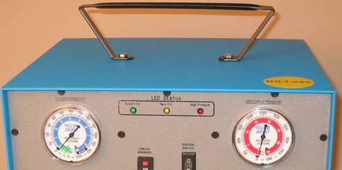
5 SUCTION PRESSURE System On Tank Full High Pressure CIRCUIT BREAKER SYSTEM SWITCH SUCTION PRESSURE SUCTION PORT DISCHARGE PRESSURE DISCHARGE PORT DISCHARGE PRESSURE O O LIQUID VAPOR PURGE RECOVER TO POWER SUPPLY liquid service port hvac unit or appliance vapor service port sight glass liquid(open) vapor(open) Figure 1 recovery tank Charging Scale PUSH-PULL LIQUID RECOVERY The Push-Pull Liquid Recovery mode is used for transferring large volumes of liquid refrigerant. The R100 Pulls vapor from the recovery cylinder and produces high pressure discharge gas that Pushes liquid out of a HVAC system into a recovery cylinder. ( see figure 1) Some systems may not allow push-pull liquid recovery. If any of the following conditions apply to your recovery job, proceed directly to Vapor Recovery. Equipment contains less than 8 pounds of refrigerant. Equipment is a heat pump or other unit with a reversing valve. Equipment has an accumulator between the service ports used in liquid recovery. Liquid refrigerant has migrated and the location of the refrigerant is not known. The refrigerant system does not allow for a solid column of liquid refrigerant to be formed. When using push-pull recovery, the R100 will not recover to the required vacuum level in the recovered system. Use a sight glass to determine when the liquid is being pushed into the recover tank. When liquid refrigerant is no longer visible, switch to Vapor Recovery (see figure 2). The hose connections for liquid push recovery are shown in the figure 1. Perform the following steps for push-pull recovery: 1. Ensure the recovery unit System Switch is OFF and the power to the system to be serviced is also turned off. 5
6 SUCTION PRESSURE System On Tank Full High Pressure CIRCUIT BREAKER O LIQUID SYSTEM SWITCH SUCTION PRESSURE SUCTION PORT VAPOR O PURGE DISCHARGE PRESSURE DISCHARGE PORT DISCHARGE PRESSURE RECOVER PUSH-PULL LIQUID RECOVERY, cont. 2. Connect the recovery unit, the system to be serviced, and the recovery tank as shown in the figure Open the valves on the recovery cylinder. 4. Turn the Suction Valve to VAPOR RECOVERY and the Discharge Valve to PURGE position. 5. Turn the System Switch ON. The Green LED should energize. 6. Monitor the sight glass. When there is no longer significant liquid refrigerant passing through the sight glass, push-pull liquid recovery is complete. Note: If the Yellow LED energizes, the recovery tank is full. Turn off power. Turn off both valves. Exchange recovery tank with an empty one. Repeat Steps 3-6. If the Red LED energizes, the recovery unit is sensing a high-pressure limit. Turn off power and check for restrictions. If tank pressure is above 400 psig, exchange tank. Repeat Steps Turn the Tank Vapor Valve to OFF. Wait until suction pressure gauge indicates a vacuum. 8. Perform PURGE process. 9. Disconnect Refrigerant hoses. 10.Proceed to the Vapor Recovery procedure in this manual to remove the remainder of the refrigerant and to evacuate the system to the required vacuum level. TO POWER SUPPLY liquid service port (Liquid Recovery mode only) hvac unit or appliance liquid(closed) vapor(open) recovery tank Charging Scale vapor service port (Liquid or Vapor Recovery mode) Figure 2 6
7 VAPOR & LIQUID (DIRECT) RECOVERY Vapor or Liquid Recovery is used to pull refrigerant directly out of the system to be serviced. The refrigerant is then transferred to a recovery tank. Liquid Recovery is used when connecting to the high pressure side of the system to be serviced or any other service port that liquid refrigerant is present. Either Vapor or Liquid Recovery can be used when connecting to the low pressure side or any other service port that vapor refrigerant is present. IMPORTANT: If you are not sure whether liquid refrigerant is present, choose Direct Liquid Mode. This mode limits the amount of liquid refrigerant entering the compressor. Recovery of liquid refrigerant in the Vapor Recovery mode can damage the compressor. If large quantities of liquid refrigerant are expected, use the liquid push-pull method. Push-pull will transfer liquid refrigerant faster than direct liquid recovery. The hose connections for vapor & liquid recovery are shown in the figure 2. To perform vapor or liquid recovery, please follow the steps below: 1. Turn off power to the system to be serviced. 2. Turn the Suction Valve to OFF and the Discharge Valve to RECOVER. 3. Connect the recovery unit, the system to be serviced, and the recovery tank as shown in the figure 2. The suction hose can be connected to the liquid and/or vapor service ports. If you connect to the liquid service port, ensure you use Liquid Recovery. Also ensure the hose to the tank is connected to the DISCHARGE port of the recovery unit. 4. Open the vapor valve on the recovery cylinder. 5. Turn the discharge valve (right) to RECOVER position. 6. Turn the System Switch ON. The Green LED should energize. 7. Turn the suction valve (left) to: VAPOR RECOVERY for vapor recovery from the vapor service port. LIQUID RECOVERY for liquid recovery from the liquid service port. CAUTION: If unsure of the refrigerant s phase, always choose the LIQUID RECOVERY position. Note: If the Yellow LED energizes, the recovery tank is full. Turn off power. Turn off both valves. Exchange recovery tank with an empty one. Repeat Steps 3-6. If the Red LED energizes, the recovery unit is sensing a high-pressure limit. Turn off power and check for restrictions. If tank pressure is above 400 psig, exchange tank. Repeat Steps After the Suction Pressure Gauge indicates the required vacuum, turn the discharge valve to PURGE to remove the remaining refrigerant from the recovery unit. 8. When the Suction Pressure Gauge indicates a vacuum, Turn the SUC- TION VALVE to OFF, Turn off the power to the recovery unit, and Disconnect the two refrigerant hoses. Recovery and Purge Operations are now complete. The R100 is ready for the next job. 7
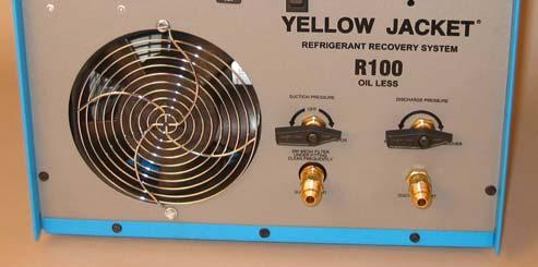
8 SUCTION PRESSURE System On CIRCUIT BREAKER Tank Full LIQUID SUCTION PRESSURE O High Pressure SYSTEM SWITCH SUCTION PORT VAPOR PURGE DISCHARGE PRESSURE O DISCHARGE PORT DISCHARGE PRESSURE RECOVER COMPONENT LOCATION AND DESCRIPTION 1. Suction Gauge - Indicates the suction pressure of the recovery unit. 2. Power Cord - 6 foot long with grounded plug to be connected to a grounded 110 volt AC power source. (not shown) 3. LED Status Lights- Green on, Yellow Tank Full, Red High Pressure Limit 4. System Switch- -Switch for turning on the recovery system compressor and fan. A 15 amp circuit breaker is integrated into the switch. 5. Discharge Gauge Indicates the discharge pressure of the recovery unit s condenser. 6. Cooling Fan - This fan provides airflow through the condenser and across the compressor. 7. Suction Valve - Valve for selecting either liquid or vapor recovery mode. The SUCTION port is closed when in the OFF position. 8. Suction Port & Filter- Fitting for connecting a refrigerant hose to the system to be recovered. Filter located under fitting. Clean or replace element. 9. Discharge Port - Fitting for connecting a refrigerant hose to the recovery tank. DISCHARGE port is closed when in the OFF position. 10. Discharge Valve Valve used to select Recovery or Purge operation. 11. Circuit Breaker 30 AMP breaker is non-integrated. 12. Tank Overfill Sensor Cord- used to connect to a tank float with a 3-prong Brad Harrison. (not shown) Shorting Cap also included. 8
9 TROUBLESHOOTING INFORMATION Problem Possible Causes Solution R100 compressor and fan will not start R100 compressor will not start but fan runs Power cord not plugged in Socket not energized High Pressure Switch activated Tank Overfill Sensor activated Circuit Breaker is tripped Defective system switch Broken or loose wire Compressor Start relay or capacitor defective Compressor thermal overload is tripped Compressor leads are broken or loose Plug in to energized socket Check socket for power Check for restrictions Check recovery tank Turn off power to reset Reset circuit breaker Replace switch Repair electrical connection Replace the relay or capacitor Thermal overload will automatically reset Repair compressor leads R100 starts but stops after a short period R100 trips circuit breaker upon start up Restriction in the discharge line tripping the high pressure switch High differential pressure across compressor suction and discharge valves Open valve on recovery tank Check for other restrictions Turn off power to reset Turn Discharge Valve to the PURGE position for 5 seconds. Return valve back to RECOVERY position. R100 will not perform liquid push-pull recovery System to be serviced does not allow liquid recovery Use Direct Recovery method TECHNICAL SUPPORT: Call this number if you require additional information on your YELLOW JACKET Unit. FOR WARRANTY OR OTHER SERVICE: Contact your YELLOW JACKET Distributor 9
10 recovery tank hvac unit or appliance recovery tank Notes: REPAIR PARTS DIAGRAM 10
11 REPAIR PARTS LIST The following list contains the major components of the R100. To order these parts, please contact your YELLOW JACKET Dealer. Please have the following information available when you call. Model: R100 Serial Number: Date of Purchase: Part Number Description Part Number Description Tank Overfill Sensor Cord Shorting Cap Power Cord 3 Compressor hoses Compressor (includes head) Suction Valve w/ Strainer Capacitor Compressor Relay Foam for Handles Low Pressure Gauge High Pressure Gauge PC Board w/remote LED s 12 G Y R Remote LED s High Pressure Switch Discharge Valve Fan Guard Circuit Breaker Rocker Switch Condenser psig Check Valve psig Check Valve Operation Manual 11
12 Recovery Division 6701 West 110th Street Bloomington, MN USA Phone: Phone: Fax: Fax: Web: 12 Printed in U.S.A. 04/06 FK
RecoverX Oil-Filled Hermetic Refrigerant Recovery System. Operation and Maintenance Manual
 RecoverX Oil-Filled Hermetic Refrigerant Recovery System Operation and Maintenance Manual Table of Contents Page General Safety Instructions 2-3 System Overview 3 Operating Guide 4 Restart Procedure 4
Operation and Maintenance Manual
 Warranty Information Ritchie Engineering guarantees YELLOW JACKET products to be free of defective material and workmanship which could affect the life of the product when used for the purpose for which
RecoverX-CAR Contaminated Automotive Refrigerant Recovery System Operation and Maintenance Manual
 RecoverX-CAR Contaminated Automotive Refrigerant Recovery System Operation and Maintenance Manual (English) Table of Contents Page General Safety Instructions...2 System Overview...3 RecoverX-CAR Operation
Oilless Refrigerant Recovery System. OWNER S MANUAL (English) TO BE OPERATED BY QUALIFIED PERSONNEL ONLY
 TO BE OPERATED BY QUALIFIED PERSONNEL ONLY") Pro-Set TR500 SERIES Oilless Refrigerant Recovery System OWNER S MANUAL (English) Français, Español, Deutsch and latest updates: www.cpsproducts.com Series: TR500, TR500E, TR500J, TR500S TO BE OPERATED
Pro-Set TR500 SERIES Oilless Refrigerant Recovery System OWNER S MANUAL (English) Français, Español, Deutsch and latest updates: www.cpsproducts.com Series: TR500, TR500E, TR500J, TR500S TO BE OPERATED
TRS21 IGNITION PROOF SERIES
 TRS21 IGNITION PROOF SERIES 2 Cylinder Commercial Recovery Machine OWNER S MANUAL (English) Français, Español, Deutsch and latest updates: www.cpsproducts.com Series: TRS21A, TRS21E TO BE OPERATED BY QUALIFIED
OWNER S MANUAL (English)
") TR600 Series Refrigerant Recovery Machines OWNER S MANUAL (English) Français, Español, Deutsch and latest updates: www.cpsproducts.com Series: TR600, TR610, TR600C, TR610C, TR600S, TR600K, TR600E TO BE
TR600 Series Refrigerant Recovery Machines OWNER S MANUAL (English) Français, Español, Deutsch and latest updates: www.cpsproducts.com Series: TR600, TR610, TR600C, TR610C, TR600S, TR600K, TR600E TO BE
OPER LV Wheeler Way
 OPER RATING INSTRUCTIONS LV5 REFRIGERANT RECOVERY UNIT NATIONAL REFRIGERATION PRODUCTS 985 Wheeler Way Langhorne, PA 19047 Ph:(215) 638-8909 9 info@ @nrproducts.com LV5.DOC 9.17.2018 MODEL LV5 REFRIGERANT
Refrigerant Recovery Machine. Model No Operating Manual
 Refrigerant Recovery Machine Model No. 25700 Operating Manual Safety Precautions WARNING : TO PREVENT PERSONAL INJURY AND / OR EQUIPMENT DAMAGE, CAUTION - Risk of injury. This equipment should only be
OPERATING INSTRUCTIONS
 OPERATING INSTRUCTIONS MODEL LV8 COMMERCIAL REFRIGERANT RECOVERY UNIT NATIONAL REFRIGERATION PRODUCTS 985 WHEELER WAY LANGHORNE, PA 19047 (215) 638-8909 FAX (215) 638-9270 A01001 7/11/96 NRP-OM-LV8 7/96
TRS21 IGNITION PROOF SERIES
 TRS21 IGNITION PROOF SERIES 2 Cylinder Commercial Recovery Machine OWNER S MANUAL (English) Français, Español, Deutsch and latest updates: www.cpsproducts.com Series: TRS21, TRS21C, TRS21S Evaluated for
High Performance Oilless Residential Light Commercial. Product Leadership Training Service Reliability
 High Performance Oilless Residential Light Commercial Product Leadership Training Service Reliability User Manual 2020-9000 Rev. 1 December 2017 WARRANTY Bacharach, Inc. (Bacharach) warrants to the buyer
99 Washington Street Melrose, MA Phone Toll Free Visit us at
 99 Washington Street Melrose, MA 02176 Phone 781-665-1400 Toll Free 1-800-517-8431 Visit us at www.testequipmentdepot.com User s Manual 1 WARNING! CAUTION! Before operating this unit, please read this
Refrigerant Recovery Unit, Model RRU134
 Installation, Operation & Maintenance Manual IOMM RRU134 Group: Refrigerant Effective: December 2000 Supersedes: New Refrigerant Recovery Unit, Model RRU134 1999 McQuay International Table of Contents
OWNER S MANUAL (English)
") TRS600 IGNITION PROOF SERIES Refrigerant Recovery Machines OWNER S MANUAL (English) Français, Español, Deutsch and latest updates: www.cpsproducts.com Series: TRS600, TRS600K, TRS600S Evaluated for performance
TRS600 IGNITION PROOF SERIES Refrigerant Recovery Machines OWNER S MANUAL (English) Français, Español, Deutsch and latest updates: www.cpsproducts.com Series: TRS600, TRS600K, TRS600S Evaluated for performance
OWNER S MANUAL (English)
") PREMIUM RECOVERY MACHINES OWNER S MANUAL (English) Français, Español, Deutsch and latest updates: www.cpsproducts.com Series: TR700C/E /J/JUK/S; TR710C/S TO BE OPERATED BY QUALIFIED PERSONNEL ONLY Evaluated
PREMIUM RECOVERY MACHINES OWNER S MANUAL (English) Français, Español, Deutsch and latest updates: www.cpsproducts.com Series: TR700C/E /J/JUK/S; TR710C/S TO BE OPERATED BY QUALIFIED PERSONNEL ONLY Evaluated
OPERATING INSTRUCTIONS
 OPERATING INSTRUCTIONS MODEL LV20 LARGE CAPACITY REFRIGERANT RECOVERY UNIT NATIONAL REFRIGERATION PRODUCTS 985 WHEELER WAY LANGHORNE, PA 19047 (215) 638-8909 FAX (215) 638-9270 R01101 LV20.DOC NRP-OM-LV20
OPERATING INSTRUCTIONS
 OPERATING INSTRUCTIONS MODEL RLV-700 REFRIGERANT RECOVERY / RECYCLING UNIT (PATENTED) NATIONAL REFRIGERATION PRODUCTS 985 Wheeler Way Langhorne, PA 19047 (215) 638-8909 FAX (215) 638-9270 REVISED 03-21-2018
OPERATION & MAINTENANCE MANUAL TC670
 OPERATION & MAINTENANCE MANUAL TC670 Refrigerant Management Center (Convertible For Use With R12 or R134a) RTI TECHNOLOGIES, INC. 4075 East Market Street York, PA 17402 Manual P/N 035-80342-02 TC670 CONVERTIBLE
Pro-Set TRA21 SERIES Mobile Multiple Refrigerant Recovery / Recycle System
 Pro-Set TRA21 SERIES Mobile Multiple Refrigerant Recovery / Recycle System Certified by ITS to meet SAE J2810 for R-134a Designed to meet new SAE J2851 for R-1234yf MANUAL GENERAL INFORMATION Table of
POLAR BREEZE Statim Technologies, LLC IMPORTANT SAFETY INSTRUCTIONS AND PRECAUTIONS
 POLAR BREEZE Statim Technologies, LLC IMPORTANT SAFETY INSTRUCTIONS AND PRECAUTIONS Use the Polar Breeze Only in the Manner Described in this Manual. This is an International Safety Alert Symbol. Failure
OPERATION & MAINTENANCE MANUAL RHS680
 OPERATION & MAINTENANCE MANUAL RHS680 Refrigerant Handling System 4075 East Market Street York, PA 17402 800-468-2321 tech@rtitech.com Manual P/N 035-80740-00 (Rev 1- May 22, 2001) TABLE OF CONTENTS Startup
Caresaver Universal Refrigerant Recovery Unit
 Operation Manual Caresaver Universal Refrigerant Recovery Unit 2 CONTENTS CHAPTER 1 INTRODUCTION AND OVERVIEW Specifications 3 Health and Safety 4-5 Component Location and Identification 6-9 CHAPTER 2
OPERATION & MAINTENANCE MANUAL TX600
 OPERATION & MAINTENANCE MANUAL TX600 RTI TECHNOLOGIES, INC. 4075 East Market Street York, PA 17402 Manual P/N 035-80118-00 (Rev B) ! TABLE OF CONTENTS! TX600 Before Using Page 2 Safety Precautions Page
14. The center port of the manifold is used for evacuation, charging and refrigerant recovery.
 HET- 190 ESL Support page 1 CORE Basic Refrigeration Circuit 1. Liquid refrigerant boils in the evaporator. Heat is absorbed. The heat energy absorbed converts refrigerant liquid into vapor. 2. Refrigerant
ENSPECO Recovery/ Recycle/ Evacuate/ Recharge
 ENSPECO Recovery/ Recycle/ Evacuate/ Recharge RMS 3012 RMS 3034 Approved by UL/SAE to J-1991 R12 Purity Standards Approved by UL/SAE to J-2210 R134 Purity Standards This semi-automatic machine will recover
Additional users operating manual
 Additional users operating manual For use with A2L Refrigerants e.g. R32, 1234yf, 143a, 1234ze This additional manual is valid for the following Promax Refrigerant Recovery Units: MiniMax-E; RG 5410A-E,
Enspeco RMS. The Enspeco Refrigerant Management. The following instructions will INSTRUCTIONS
 Enspeco AUTOMOTIVE REFRIGERANT MANAGEMENT SYSTEMS RMS 5000 INSTRUCTIONS The Enspeco Refrigerant Management System 5000 provides fast and efficient recovery, recycling and charging of automotive air conditioning
WMHP Series R410a Heat Pump INSTALLATION INSTRUCTIONS
 WMHP Series R410a Heat Pump INSTALLATION INSTRUCTIONS **WARNING TO INSTALLER, SERVICE PERSONNEL AND OWNER** Altering the product or replacing parts with non authorized factory parts voids all warranty
Owner s Manual Refrigerated Compressed Air Dryers Models F-3528, F-3529, F-3530, F-3531 & F-3532
 Owner s Manual Refrigerated Compressed Air Dryers Models F-3528, F-3529, F-3530, F-3531 & F-3532 Read carefully before attempting to assemble, install, operate or maintain the product described. Protect
Owner s Manual Refrigerated Compressed Air Dryers Model F-100
 Owner s Manual Refrigerated Compressed Air Dryers Model F-100 Read carefully before attempting to assemble, install, operate or maintain the product described. Protect yourself and others by observing
INSTALLATION INSTRUCTIONS
 INSTALLATION INSTRUCTIONS T CLASS TSA Series 6 to 20 Ton AIR CONDITIONERS 6 20 TONS 506147 01 06/11 Supersedes 3/11 Litho U.S.A. RETAIN THESE INSTRUCTIONS FOR FUTURE REFERENCE IMPORTANT The Clean Air Act
MODEL 7000 SUCTION UNIT
 MODEL 7000 SUCTION UNIT OPERATOR S MANUAL Caution Federal law restricts this device to sale by or on order of a physician, or any other practitioner licensed by the law of the State in which he practices
Owner s Manual. Model AC375C Refrigerant Recovery, Recycle, and Recharge Unit
 Owner s Manual Model AC375C Refrigerant Recovery, Recycle, and Recharge Unit Model AC375C Recover, Recycle, and Recharge Unit for R-12 or R-134a Refrigerant Voltage: 220 230; 50 60 Hz SAFETY DEFINITIONS:
OPERATION & MAINTENANCE MANUAL AC860
 OPERATION & MAINTENANCE MANUAL AC860 Refrigerant Handling System Manual P/N 035-80913-00 TABLE OF CONTENTS Startup & Safe Operation... 1 Introduction to the AC860... 2 Control Panel... 3 Keypad Functions...
OWNER S MANUAL FOR AIR ADMIRAL VACUUM/PRESSURE STATION MODELS:
 OWNER S MANUAL FOR AIR ADMIRAL VACUUM/PRESSURE STATION MODELS: 79202-00 79202-05 79202-30 79202-35 Approval Agency s Model 79202-00 & 79202-05 Model 79202-30 & 79202-35 Not recommended for pumping acid,
INDUSTRIAL - SOLVENT PARTS CLEANER CM200 (115V OR 230V PUMP)
") INDUSTRIAL - SOLVENT PARTS CLEANER OPERATION & INSTRUCTION MANUAL I. Introduction A. Manufacturer s Statement CM200 (115V OR 230V PUMP) This manual will provide you with important information about the
INDUSTRIAL - SOLVENT PARTS CLEANER OPERATION & INSTRUCTION MANUAL I. Introduction A. Manufacturer s Statement CM200 (115V OR 230V PUMP) This manual will provide you with important information about the
BG8SS. 8 Inch Slow Speed Bench Grinder with LED Lights Assembly & Operating Instructions
 BG8SS 8 Inch Slow Speed Bench Grinder with LED Lights Assembly & Operating Instructions READ ALL INSTRUCTIONS AND WARNINGS BEFORE USING THIS PRODUCT. SAVE THESE INSTRUCTIONS FOR FUTURE REFERENCE. This
ELECTRIC FIREPLACE CONVERTER KIT OWNERS MANUAL Model Number: EF05-23
 ELECTRIC FIREPLACE CONVERTER KIT OWNERS MANUAL Model Number: EF05-23 AC 120V ~ 60Hz ~ 1400W Only use this heater as described in this manual. Any other use is not recommended by the manufacturer, and may
ariazone 601HD Refrigerant Recovery & Recycling Unit User's manual
 ariazone 601HD Refrigerant Recovery & Recycling Unit User's manual Model: Ariazone 601 HD Serial No: 1 1. SAFETY FIRST! Important safety information's - Read this user manual carefully before operating
Air Conditioning Operation and Troubleshooting Matt Dunham
 Air Conditioning Operation and Troubleshooting Matt Dunham Major Components (10 Minutes) Compressor heart of the system, causes refrigerant to flow by increasing the pressure of the refrigerant Metering
5) Do not start or stop the unit by inserting or pulling out the power plug.
 Do not start or stop the unit by inserting or pulling out the power plug.") 3058080 V170306 PURCHASE INFORMATION Thank you for choosing a Soleus Air Portable Air Conditioner. This Owner s Manual will provide you with valuable information necessary for the proper care and maintenance
3058080 V170306 PURCHASE INFORMATION Thank you for choosing a Soleus Air Portable Air Conditioner. This Owner s Manual will provide you with valuable information necessary for the proper care and maintenance
DLCLRA. INSTALLATION INSTRUCTIONS Outdoor Unit Single Zone Ductless System Sizes 36 to 58 TABLE OF CONTENTS
 DLCLRA INSTALLATION INSTRUCTIONS Outdoor Unit Single Zone Ductless System Sizes 36 to 58 Fig. 1 - Size 36 TABLE OF CONTENTS PAGE SAFETY CONSIDERATIONS... 2 PARTS LIST... 3 SYSTEM REQUIREMENTS... 4 WIRING...
B. A. T. Basic Appliance Training
 B. A. T. Basic Appliance Training BASIC REFRIGERATION presented by Phil Whitehead Program Objective The objective of this program is to give you some of the basic elements that are essential to understanding
GENERAL 2004 HVAC SYSTEMS. Manual HVAC System - Sorento SPECIFICATIONS. Fig. 1: Air Conditioner Specifications Courtesy of KIA MOTORS AMERICA, INC.
 Fig. 2: Blower & Evaporator Unit Specifications 2004 HVAC SYSTEMS Manual HVAC System - Sorento GENERAL SPECIFICATIONS AIR CONDITIONER Fig. 1: Air Conditioner Specifications BLOWER AND EVAPORATOR UNIT HEATER
BG6UL. 6 Inch Bench Grinder Assembly & Operating Instructions
 BG6UL 6 Inch Bench Grinder Assembly & Operating Instructions READ ALL INSTRUCTIONS AND WARNINGS BEFORE USING THIS PRODUCT. SAVE THESE INSTRUCTIONS FOR FUTURE REFERENCE. This manual provides important information
CLASSIC PLUS INFRARED ZONE HEATER
 CLASSIC PLUS INFRARED ZONE HEATER OWNER S MANUAL Model No. A5835 IMPORTANT SAVE THESE INSTRUCTIONS To ensure you get the best results, please read this manual first and keep it for future reference. For
Schuco byallied MEDICAL ASPIRATOR. USER'S MANUAL A Caution
 S168-544-OO1E REV.A Schuco byallied MEDICAL ASPIRATOR MnrInI -33OA USER'S MANUAL A Caution Federal law restricts this device to sale by or on order of a physician, or any other practitioner licensed by
12 VELOCITY OWNER S MANUAL OPERATING INSTRUCTIONS - MAINTENANCE - SAFETY - TROUBLESHOOTING
 12 VELOCITY OWNER S MANUAL OPERATING INSTRUCTIONS - MAINTENANCE - SAFETY - TROUBLESHOOTING This manual contains very important safety warnings and information. Read and save these instructions for future
Owner s Manual Refrigerated Compressed Air Dryers Models F-200, 250, 300 & F350
 Owner s Manual Refrigerated Compressed Air Dryers Models F-200, 250, 300 & F350 Read carefully before attempting to assemble, install, operate or maintain the product described. Protect yourself and others
3-1/2 GALLON PARTS WASHER OPERATING INSTRUCTION AND PARTS MANUAL. Model # 4KTV9
 3-1/2 GALLON PARTS WASHER OPERATING INSTRUCTION AND PARTS MANUAL Model # 4KTV9 QUALITY GUARANTEE: Should a Westward product fail to perform satisfactorily due to defect or poor workmanship within one
PS /2 Inch Angle Grinder Assembly & Operating Instructions READ ALL INSTRUCTIONS AND WARNINGS BEFORE USING THIS PRODUCT.
 PS07214 4 1/2 Inch Angle Grinder Assembly & Operating Instructions READ ALL INSTRUCTIONS AND WARNINGS BEFORE USING THIS PRODUCT. This manual provides important information on proper operation & maintenance.
Model No. GB-PAC-08E4. 8,000 BTU Portable Air Conditioner Operating Instructions
 Model No. GB-PAC-08E4 8,000 BTU Portable Air Conditioner Operating Instructions Thank you for choosing a Soleus Air Powered by Gree Portable Air Conditioner. This owner s manual will provide you with valuable
TABLE OF CONTENTS. NOTE: Read the entire instruction manual before starting the installation. TROUBLESHOOTING... 13
 R 410A Duct Free Split System Air Conditioner and Heat Pump Product Family: DFS4(A/H) System, DFC4(A/H)3 Outdoor, DFF4(A/H)H Indoor NOTE: Read the entire instruction manual before starting the installation.
TROUBLESHOOTING VANGUARD
 TROUBLESHOOTING VANGUARD IMPORTANT: Only a qualified Service Person should service internal components or electrical wiring. WARNING: Disconnect electrical power to the Unit to prevent personal injury
Radiant Heater. Instruction Manual QH-200 N13275
 Radiant Heater Instruction Manual QH-200 N13275 2 Contents Important Safety Instructions 3 Product Overview 6 Getting Started 7 Instructions 8 Other Useful Information 10 Important Safety Instructions
Residential Piping and Long Line Guideline
 AC / HP R-410A Refrigerant Systems Single-Stage, Two-Stage and Variable Speed Models Residential Piping and Long Line Guideline TABLE OF CONTENTS Safety Considerations... 2 Definitions... 2 Introduction...
π H-6621 INDUSTRIAL DEHUMIDIFIER WARNINGS SPECIFICATIONS uline.com WATER REMOVAL ELECTRICAL REQUIREMENTS BUILT-IN ELECTRICAL SAFETY
 π H-6621 INDUSTRIAL DEHUMIDIFIER 1-800-295-5510 uline.com WARNINGS Plug into a grounded 3 prong outlet. Do not remove ground prong. Do not use an adapter. Do not use an extension cord if possible. Failure
REFRIGERANT RECOVERY SYSTEMS
 REFRIGERANT RECOVERY 99 Washington Street Melrose, MA 02176 Phone 781-665-1400 Toll Free 1-800-517-8431 Visit us at www.testequipmentdepot.com RECOVERY YELLOW JACKET HVAC&R HOSES YELLOW JACKET YJ-LTE Refrigerant
347002K/177002K/34900
 Service Manual Models: 347002K/177002K 34900/347012K Manifold Block Style Recovery/Recycling/Recharging Unit For R-12 or R-134a Only TABLE OF CONTENTS: Theory of Operation and Safety Precautions... 2 Depressurizing
Truck Edition V-220 / V-320 Series Single Temperature Systems TK IM (Rev. 0, 06/17)
") Installation Manual Truck Edition V-220 / V-320 Series Single Temperature Systems TK 56321-18-IM (Rev. 0, 06/17) Installation Manual Truck Edition V-220 / V-320 Series Single Temperature Systems TK 56321-18-IM
Installation Manual Truck Edition V-220 / V-320 Series Single Temperature Systems TK 56321-18-IM (Rev. 0, 06/17) Installation Manual Truck Edition V-220 / V-320 Series Single Temperature Systems TK 56321-18-IM
Gallery Electric Fireplaces
 Gallery Electric Fireplaces Homeowner s Installation Instructions & Operating Manual Model: GBI-34, GBI-41 Only use this heater as described in this manual. Any other use is not recommended by the manufacturer,
Installation Instructions
 38MHR Outdoor Unit Single Zone Ductless System Sizes 09 to 24 Installation Instructions NOTE: Read the entire instruction manual before starting the installation. NOTE: Images are for illustration purposes
REFRIGERANT SYSTEM SERVICE WARNINGS
 2005 HVAC Refrigerant System - MX-5 Miata REFRIGERANT SYSTEM SERVICE WARNINGS USING/HANDLING UNAPPROVED REFRIGERANT Using a flammable refrigerant, such as OZ-12, in this vehicle is dangerous. In an accident,
CS/CD/CP AIR COOLED CONDENSING UNITS (P/N E207120C R2)
") CS*/CD*/CP* Series Air Cooled Condensing Units Operating and Installation Manual CS/CD/CP AIR COOLED CONDENSING UNITS (P/N E207120C R2) TABLE OF CONTENTS I. Receipt of Equipment 2 II. Piping...4 III. System
CS*/CD*/CP* Series Air Cooled Condensing Units Operating and Installation Manual CS/CD/CP AIR COOLED CONDENSING UNITS (P/N E207120C R2) TABLE OF CONTENTS I. Receipt of Equipment 2 II. Piping...4 III. System
NON-CYCLING REFRIGERATED AIR/GAS DRYERS QPNC 75 to QPNC 250 OPERATOR S MANUAL
 NON-CYCLING REFRIGERATED AIR/GAS DRYERS QPNC 75 to QPNC 250 OPERATOR S MANUAL DATE OF PURCHASE: MODEL: SERIAL NO.: Record above information from nameplate. Retain this information for future reference.
User manual Flushing device VAS 6337/1a
 User manual Flushing device VAS 6337/1a 2 Content Safety warnings 3 Flushing with R134a refrigerant 4 1.0 Preparing the Vehicle AC System 4 1.1 Connecting the recovery recharge Unit 6 1.2 Flush procedure
Ariazone 601HD Refrigerant Recovery&Recycling unit
 Automotive Air-Conditioning Service Equipment Ariazone 601HD Refrigerant Recovery&Recycling unit OPERATOR MANUAL 1 1. SAFETY FIRST! Important safety information's - Read this user manual carefully before
WET/DRY VACUUM. QUEST for Continuous Improvement Windsor s Quality Management System is Certified ISO MODEL: T1. Operating Instructions (ENG)
") WET/DRY VACUUM Operating Instructions (ENG) MODEL: T1 y QUEST for Continuous Improvement Windsor s Quality Management System is Certified ISO 9001. Read these instructions before operating the machine.
WET/DRY VACUUM Operating Instructions (ENG) MODEL: T1 y QUEST for Continuous Improvement Windsor s Quality Management System is Certified ISO 9001. Read these instructions before operating the machine.
HNC-120BE-L/R-B HNC-150BE-L/R-B HNC-180BE-L/R-B HNC-210BE-L/R-B COUNTER SHOWCASE MODEL SERVICE MANUAL HOSHIZAKI
 NO. S051-800 ISSUED: MAR. 26, 2010 REVISED: HOSHIZAKI COUNTER SHOWCASE MODEL HNC-120BE-L/R-B HNC-150BE-L/R-B HNC-180BE-L/R-B HNC-210BE-L/R-B SERVICE MANUAL IMPORTANT This manual should be read carefully
EarthLinked CC Series Compressor Unit R-410A Quik-Start Instructions
 EarthLinked CC Series Compressor Unit R-410A Quik-Start Instructions CONTENTS PAGE Pre-Installation 3 Placement & Mechanical Information 4 System Application Options 11 Desuperheater Kit 15 Anti-Freeze
1 HP Air Mover. Owner s Manual
 1 HP Air Mover Owner s Manual WARNING: Read carefully and understand all ASSEMBLY AND OPERATION INSTRUCTIONS before operating. Failure to follow the safety rules and other basic safety precautions may
ELECTRIC STOVE MODEL CGESS SAFETY INFORMATION AND OPERATION MANUAL
 ELECTRIC STOVE MODEL CGESS SAFETY INFORMATION AND OPERATION MANUAL Read these instructions completely before operating electric stove. Failure to follow them could cause a heater malfunction resulting
Split Portable Air Conditioner
 SP-IOM-1 Please read and save this manual. Read carefully before attempting to assemble, install, operate or maintain the product described. Protect yourself and others by observing all safety information.
SERVICING PROCEDURE R-410A LEAK TEST EVACUATION CHARGING. Bard Manufacturing Company, Inc. Bryan, Ohio Manual Page 1 of 11
 SERVICING PROCEDURE R-410A LEAK TEST EVACUATION CHARGING Bard Manufacturing Company, Inc. Bryan, Ohio 43506 Since 1914...Moving ahead, just as planned. Manual No.: 2100-479 Supersedes: NEW File: Volume
4-GALLON MOBILE PARTS WASHER
 Please read and save these instructions. Read through this owner s manual carefully before using product. Protect yourself and others by observing all safety information, warnings, and cautions. Failure
INFRARED PARAFfIN / KEROSENE / model No: ir20.v2 1. SAFETY INSTRUCTIONS RECOMMENDED FUSE RATING: 5AMP
 InstructioNS for: INFRARED PARAFfIN / KEROSENE / diesel HEATER model No: ir20.v2 Thank you for purchasing a Sealey product. Manufactured to a high standard this product will, if used according to these
Portable Air Conditioner 6,000 BTU 8,000 BTU 10,000 BTU
 Portable Air Conditioner 6,000 BTU 8,000 BTU 10,000 BTU OPERATING INSTRUCTIONS PCR-06-01 PCR-08-01 PCR-10-01 3058080 V170223 PURCHASE INFORMATION Thank you for choosing a Chigo Portable Air Conditioner.
Surna 25-Ton Chiller Operating & Maintenance Manual
 www.surna.com 303.993.5271 Surna 25-Ton Chiller Operating & Maintenance Manual Models: 300F3-3. 300F4-3, 300FW-3 Revised: July 2015 Table of Contents Warranty Information 4 Limited Warranty 4 Limitation
ZCR 3824 SAFETY INFORMATION AND OPERATIONS MANUAL
 ZCR 3824 SAFETY INFORMATION AND OPERATIONS MANUAL Read these instructions completely before beginning installation. Failure to follow them could cause a heater malfunction resulting in serious injury and/or
SECTION 7 AIR CONDITIONING (COOLING) UNIT 41 TROUBLESHOOTING
 UNIT 41 TROUBLESHOOTING") SECTION 7 AIR CONDITIONING (COOLING) UNIT 41 TROUBLESHOOTING UNIT OBJECTIVES After studying this unit, the reader should be able to Select the correct instruments for checking an air conditioning unit
SECTION 7 AIR CONDITIONING (COOLING) UNIT 41 TROUBLESHOOTING UNIT OBJECTIVES After studying this unit, the reader should be able to Select the correct instruments for checking an air conditioning unit
Condensing Unit Installation and Operating Instructions
 Bulletin WCU_O&I 01 June 2003 Condensing Unit Installation and Operating Instructions WCU Air Cooled Condensing Unit Table of Contents Section 1. Section 2. Section 3. Section 4. Section 5. Section 6.
S150 S300 CONSTRUCTION HEATERS. Rev: August 15, 2008 SERVICE AND MAINTENANCE MANUAL No PLEASE RETAIN FOR FUTURE REFERENCE PRODUCTS
 S150 & S300 CONSTRUCTION HEATERS Rev: 2.7.2 August 15, 2008 SERVICE AND MAINTENANCE MANUAL No. 934-6637 PLEASE RETAIN FOR FUTURE REFERENCE PRODUCTS A DIVISION OF HAUL-ALL EQUIPMENT LTD. 4115-18 Avenue
INSTRUCTION MANUAL WET / DRY VACUUM VC HP V 60 Hz 7A. Gal
 INSTRUCTION MANUAL WET / DRY VACUUM VC445 Note : Read and understand this manual before use. Keep this manual for future reference. 4HP 4.5 Gal 20 V 60 Hz 7A When using an electrical appliance, basic precautions
a. CFCs. b. HCFCs. c. Pressurized nitrogen. d. Compressed dry air. 17. The state of the refrigerant leaving the condenser of a refrigeration system
 Core 1. Ozone in the stratosphere above the earth consists of: a. Molecules containing 3 oxygen atoms. b. Molecules of 2 oxygen atoms. c. Radioactive particles. d. Pollutants that have risen from ground
OPERATION & MAINTENANCE MANUAL AC880
 OPERATION & MAINTENANCE MANUAL AC880 Refrigerant Handling System Manual P/N 035-80749-00 TABLE OF CONTENTS AC880 Before Using the AC880... 2 Safety Precautions... 2 Using the AC880... 3 Setup... 4 Fill
HTD. High Temperature Non-Cycling Refrigerated Compressed Air Dryers. Operation & Maintenance Manual. MODELS HTD 21 thru HTD 100
 HTD High Temperature Non-Cycling Refrigerated Compressed Air Dryers Operation & Maintenance Manual MODELS HTD 21 thru HTD 100 - TABLE OF CONTENTS - 1.0 GENERAL 2 1.1 How to use this manual 1.2 Symbols
SECTION 50 - CAB CLIMATE CONTROL
 AIR CONDITIONING SYSTEM DYNAMIC DESCRIPTION The refrigerant circuit of the air conditioning system contains five major components: Compressor, Condenser, Receiver/Drier, Expansion Valve, and Evaporator.
LABORATORY AIR COMPRESSORS AND VACUUM PUMPING SYSTEMS
 SECTION 22 20 00 LABORATORY AIR COMPRESSORS AND VACUUM PUMPING SYSTEMS PART 1 - GENERAL 1.1 RELATED DOCUMENTS: A. The Conditions of the Contract and applicable requirements of Division 1, "General Requirements",
11,000 BTU Portable Air Conditioner with dehumidifier & Fan PE4-11R-03 Operating Instructions. Model No. PE4-11R Soleus Air International
 11,000 BTU Portable Air Conditioner with dehumidifier & Fan PE4-11R-03 Operating Instructions Model No. PE4-11R-03 2006 Soleus Air International Thank you for choosing a Soleus Air Portable Air Conditioner.
model No: ir20.v2 FUSE
 InstructioNS for: model No: ir20.v2 INFRARED PARAFfIN / KEROSENE / diesel HEATER 70000Btu 230V Thank you for purchasing a Sealey product. Manufactured to a high standard this product will, if used according
ULTRA LOW TEMPERATURE FREEZER. User Manual
 ULTRA LOW TEMPERATURE FREEZER User Manual Note:Kaltis reserves the right to modify any parts of this manual without prior notice. 1. No part of this manual may be reproduced in any form, or translated
8070 Mytee Lite. Instructions for. Please read before use. Register your product at support/register.
 Instructions for 8070 Mytee Lite Please read before use. Register your product at http://www.mytee.com/ support/register Model # Serial # Form # ADP-8070 06-16 1 GENERAL INFORMATION Dear Customer: Congratulations
R410a Installation and fault finding training
 R410a Installation and fault finding training Contents: General introduction Disassembly and reassembly Installation guide Trouble shooting General introduction: 1. Product Introduction Development Specification
- 1 - Updated on 18 March, 2010
 - 1 - Updated on 18 March, 2010 TABLE OF CONTENTS 1. SPECIFICATION & PARTS IDENTIFICATION...3 2. OPERATION & FUNCTION OF PARTS...4, 5 A. Cooling Operation B. Heating Operation C. Function of Parts 3. LOCATION
IMpORTANT SAFETy INSTRUcTIONS
 Table of contents SAFETy SETUp OpERATION MAINTENANcE Safety... 2 Specifications... 4 Setup... 4 Operation... 6 WARNING SyMBOLS AND DEFINITIONS Maintenance... 9 Parts List and Diagram... 10 Warranty...
Operation Manual SCT14B and SCT18B. Inspection. 3 General Description. 3 General Requirements. 3 Standard Features.
 Spot Cooling Systems, Inc. 120 Century Drive Suite 00 Carrollton, TX 7006 00-6-776 Operation Manual SCT1B and SCT1B Warning! Improper installation, adjustment, alteration, service, or maintenance can cause
V-220 / V-320 Heater Kits Installation Instructions TK IM (Rev. 0, 06/17)
") Installation Manual V-220 / V-320 Heater Kits Installation Instructions TK 56340-18-IM (Rev. 0, 06/17) Installation Manual V-220 / V-320 Heater Kits Installation Instructions TK 56340-18-IM (Rev. 0, 06/17)
Installation Manual V-220 / V-320 Heater Kits Installation Instructions TK 56340-18-IM (Rev. 0, 06/17) Installation Manual V-220 / V-320 Heater Kits Installation Instructions TK 56340-18-IM (Rev. 0, 06/17)
a. CFCs. b. HCFCs. c. Pressurized nitrogen. d. Compressed dry air. 17. The state of the refrigerant leaving the condenser of a refrigeration system
 Core 1. Ozone in the stratosphere above the earth consists of: a. Molecules containing 3 oxygen atoms. b. Molecules of 2 oxygen atoms. c. Radioactive particles. d. Pollutants that have risen from ground
INSTALLATION INSTRUCTIONS
 INSTALLATION INSTRUCTIONS T CLASS TPA Series HEAT PUMPS 7.5 TO 10 TONS 506148 01 12/08 Litho U.S.A. RETAIN THESE INSTRUCTIONS FOR FUTURE REFERENCE IMPORTANT The Clean Air Act of 1990 bans the intentional
NEUTRONICS MINI ID R-1234yf REFRIGERANT IDENTIFIER OPERATION MANUAL
 NEUTRONICS MINI ID R-1234yf REFRIGERANT IDENTIFIER OPERATION MANUAL 456 Creamery Way, Exton, PA 19341, USA Phone: 610.524.8800 Fax: 610.524.8807 Email: info@refrigerantid.com www.refrigerantid.com Page