Internal/External Wall/Window Fan Range GX6. Installation and maintenance instructions Retain for future use
|
|
|
- Todd Thornton
- 6 years ago
- Views:
Transcription

1 Internal/External Wall/Window Fan Range GX6 Installation and maintenance instructions Retain for future use

")
2 A GLASS WINDOW B C D ( 6 see F ) 13
3 E1 E2 E3
4 G1
5 G2 G3
6 G4 H
7 I
8 GB Xpelair GX6, GXC6, GXC6T, GX6HT & GX6HT2 Installation and Operating Instructions LEAVE THIS INSTRUCTION LEAFLET WITH THE FAN, FOR THE BENEFIT OF THE USER. Installing the fan This appliance is not intended for use by persons (including children and the infirm) with reduced physical, sensory or mental capabilities, or lack of experience and knowledge, unless they have been given supervision or instruction concerning use of the appliance by a person responsible for their safety. Children should be supervised to ensure that they do not play with the appliance. This appliance is intended for connection to fixed wiring. Check that the electrical rating shown on the appliance matches the mains supply. WARNING: THIS APPLIANCE MUST BE EARTHED. All installations must be supervised by a qualified electrician. Installation and wiring must conform to current IEE regulations (UK), local or appropriate regulations (other countries). If you have any queries before installing these products or after they have been installed, call the Xpelair Technical Hotline +44 (0) Our engineers are there to help you during normal office hours (UK only) and may be faxed at all other times +44 (0) Customers outside the UK please contact your local Xpelair distributor, details of which are available from the UK office. Description The GXC6 models have the following features: l Window/wall/panel/roof mounting options. GX6 l For remote switch operation. l Single speed extract operation. GXC6 l Integral pull cord operation. l Single speed extract operation. GXC6T l Integral pull cord operation. l Integral timer facility. l Single speed extract operation. GX6T l For remote switch operation. l Integral timer facility. l Single speed operation. GX6HT l For remote switch operation. l Integral humidistat/timer facility. l Single speed operation. GX6HT2 l For remote switch operation. l Integral pull cord operation. l Integral humidistat/timer facility. l Two speed operation. What the installer will need l A means for disconnection in all poles must be provided in the fixed wiring in accordance with the wiring rules. l If metal switch boxes are used, earthing regulations must be followed. l The GX6, GXC6 and GXC6T require suitably rated 3-core cable (see Installing switches and cables section). l The GX6T, GX6HT and GX6HT2 require suitably rated 4- or 5-core cable (see Installing switches and cables section). l The GX6T, GX6HT and GX6HT2 requires a wall or ceiling mounted on/off switch with built-in indicator light. For external boost/triggering, two switches are required. l 6mm blade large screwdriver, 3mm blade electrician s screwdriver and No.1 & 2 Pozidriv screwdrivers. If window mounting the fan, you will also need: l A single glazed window with a minimum glass thickness of 4mm or a double glazed unit with a preprepared sealed hole. If wall mounting the fan, you will also need: l Masonry drill, hammer & chisel (or core drill equipment, if available). l Mortar (to make good the hole). l Wall kit WK6/300 (available from Xpelair) for walls up to 300mm (12") thick or WK6/450 (available from Xpelair) for walls up to 450mm (18") thick. l 4 mounting fasteners (use fasteners suitable for wall type. Recommended screw size for standard brick No.8 x 38mm Pan Head). Where to locate the Fan l Locate it as high as possible. l At least 145mm from edge of the wall/window frame to the hole centre (see Fig. A.). l As far as possible from and opposite to the main source of air replacement to ensure airflow across the room (e.g. opposite an internal doorway). l Near the source of steam or odours. l Not where ambient temperatures are likely to exceed 50ºC. l If installed in a kitchen, fans must not be mounted immediately above a cooker hob or eye level grill. l When the fan in installed in a room containing a fuel burning appliance, precautions must be taken to avoid the backflow of gasses into the room from the open flue of the burning appliance. l When Intended for use in possible chemical corrosive atmospheres, consult our technical service department. (For overseas markets contact your local Xpelair Distributor.) l This electrical product, if installed in a shower room or bathroom, must be situated so that it cannot be touched by persons making use of the bath or shower. Installing the switches and cables 1. Check that there are no buried pipes or cables (e.g. electricity, gas, water) behind the switch location (in the wall or above the ceiling). 2. Lay in the cable from the isolating switch to the fan location via the on/off switch (see Fig.E1), SW1 (see Fig. E2.) and external boost SW1 (see Fig.E3) if required. 3. Lay in the cable from the isolating switch to the point of connection to the mains supply. WARNING: DO NOT MAKE ANY CONNECTIONS TO THE ELECTRICAL SUPPLY AT THIS STAGE. 4. Install the isolating switch and the on/off switch (see Fig.E1), SW1 (see Fig.E2) and external boost SW2 (see Fig.E3) if required. 5. Make all connections within the isolating switch and the on/off switch if required. Note: When installed in a bathroom all switches must be of a pull cord type and must be situated so that they cannot be touched by persons making use of the bath or shower. For Australia only These models are permanently connected to the supply and operation is controlled by a remote switch. They should be directly wired to the supply through an approved 10A wall-mounted surface switch with at least 3mm clearance between contacts. Preparing the hole If working above ground level, appropriate safety precautions must be observed. WARNING: EYE PROTECTION MUST BE WORN DURING ALL DRILLING AND CHISELLING OPERATIONS. If installing in a wall 1. Check there are no buried pipes or cables in the wall or obstructions on the outside (e.g. electricity, gas, water). 2. Ensure that the centre of the hole is located at least 145mm from the edges of the wall. 3. Mark on the centre of the duct hole. 4. Use this centre to draw a circle to suit the wall duct (203mm diameter for a WK6/300 or WK6/450). If core drill equipment is available 5a. Use as directed by the core drill manufacturer. If core drill equipment is not available 5b. Drill a centre hole right through the wall. 5. Cut the hole. Do not cut right through the wall (the recommended method is to drill a series of holes, close together, around the edge of the cutting line and remove the brick between the holes with a chisel). 7. Go outside and cut a hole in the outer wall, repeating the process described above. 8. Fit the ducting. Ensuring that the duct slopes down away from the fan to allow drainage of any incoming rain water to the outside. 9. Make good the hole. Allow for mortar to set before continuing with the installation. If installing in a window Obtain a ready cut pane with a correctly located hole 184mm diameter. (See Fig.A). Preparing the Fan for installation 1. For window mounting, use the two short ladder strips supplied with the fan. For wall mounting, use the longer strips supplied with the wall kit WK6/300 or WK6/ Secure the two ladder strips to the outer grille by positioning them over the hook moulding and snapping into position. 3. Ensure after fitting the hook moulding that the gasket is in the correct position. (See Fig.B). 4. Insert the two screw covers in the two fixing holes in the outer grille.
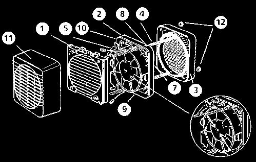
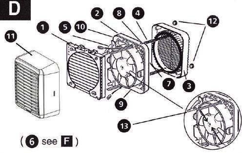
9 Mounting the fan in the hole Fig. C If working above ground floor level, appropriate safety precautions must be observed. Remove the Back Draught Shutter/Grille Assembly, by pressing the release catches located on the sides of the unit with a 6mm screwdriver or coin, whilst pulling the grille forward. If fixing with ladder strips 1. Hold up the outer grille to the outside of the wall or window so that the hole in the outer grille is aligned with the hole in the wall or window. 2. If wiring from the rear, remove the fans terminal cover and rear entry knockout. Feed the cable through the top cable entry. 2b. If wiring from above, remove fans terminal cover and feed the cable through the top cable entry. 3. Hold the fan assembly to the inside of the wall or window and guide the ladder strips from the outer grille through the slots in the fan assembly. 4. Insert the slotted screws into the pockets around the ladder strip slots. 5. Tighten the screws carefully to make a good seal. Do not over tighten the screws. 6. Trim the ladder strips back to the required length, if necessary remove any sharp edges. If using screw fixings 1. Hold the outer grille up to the outside of the wall so that the hole in the outer grille is aligned with the hole in the wall. 2. Mark the positions of the fixing holes in the top right and bottom left corners. 3. Drill the holes and insert anchor fixings to suit the wall. 4. Screw the outer grille securely in place and fit screw caps in place. Do not over tighten screws. 5. Insert the two screw covers in the two fixing holes in the outer grille. 6a. If wiring from the rear, remove the fans terminal cover, and rear entry knockout. Feed the cable through the knockout. 6b. If wiring from above, remove the fans terminal cover and feed the cable through the top cable entry. 7. Hold the fan assembly to the inside of the wall so that the spigot is inserted into the wall duct. 8. Mark the position of the two fixing holes in the top left and bottom right corners. 9. Remove the fan assembly, drill the holes and insert anchor fixings appropriate to the type of wall. 10. Reposition the cable and fan assembly as before, and screw securely in place. Do not over tighten screws. Note: For particularly difficult installations, it is possible to secure the fan with a combination of screw and ladder strip fixings. Wire the electrical connection 1. Wire the switch cable into the terminal connections shown: l Fig.E1 for GX6/GXC6/GXC6T. l Fig.E2 for GX6T/GX6HT. l Fig.E3 for GXHT2. 2. If the fan is wired from above, ensure the outer sheath of cable is retained in the labyrinth (see Fig.C). 3. Refit and secure terminal cover. 4. Refit the back draught shutter/grille assembly by sliding the grille back over the release catches, the catches will locate and secure the grille. 5. Switch off the mains electricity supply and remove fuses. 6. Connect the cable from the isolation switch to the electrical supply wiring. 7. Replace the fuses and switch on the mains electrical supply. For fixed wiring circuits the protective fuse for the appliances must not exceed 5A. Note: If using an external boost switch for the GX6HT2 (see Fig.E3), cut off the pull cord after ensuring that it is in the off position. This switch must be marked with suitable markings to indicate speed control. Operating the Fan l These fans are single speed, except the GX6HT2 which is two speed, and all are non reversible (extract only). l The shutters have a time delay of up to 1 minute on opening and up to 3 minutes on closing. Activated by operation of the switch, the delay ensures quiet operation (except GXC6 model). For Australia Only: WARNING Children should not play with the appliance. Young children and the infirm should be supervised. GX6 l The fan is operated by a remote switch. GXC6 l The fan is operated by an integral pull cord. l To switch on, pull down the cord and then release it. l Repeat to switch off. GXC6T l The fan is operated by an integral pull cord. l To switch on, pull down the cord and then release it. l Repeat to switch off. l The integral timer provides an adjustable overrun period after the fan has been switched off. GX6T l The fan is operated by a remote switch. The fan indicator light shows when it is switched on. l An integral timer provides an adjustable overrun period after the fan is switched off. GX6HT Condensation operation l The fan operates automatically if the relative humidity is above the set level. l The integral timer provides an adjustable overrun period after the relative humidity level has fallen. Switched operation l A manual operation remote switch starts the fan. The fan indicator light shows when it is switched on. l The integral timer provides an adjustable overrun period after the fan has been switched off. GX6HT2 Condensation operation l The fan operates automatically at low speed if the relative humidity rises above the set level. l The integral timer provides an adjustable overrun period after the fan has been switched off. Boost operation l The integral pull cord switches the fan on to run at high speed. The fan indicator light shows when high speed has been selected. l A remote switch may be used as an alternative to the pull cord. If this is used, cut off the pull cord, after ensuring that the pull cord switch is in the off position. GX6T/GXC6T/GX6HT and GX6HT2 only Before making any adjustments, isolate the fan completely from the mains electricity supply. Adjusting the timer overrun The overrun timer is factory preset at approximately 20 minutes. The time is adjustable between approximately 2 to 20 minutes. 1. Remove the back draught shutter/grille assembly (see Mounting the fan in the hole section). 2. Turn the adjuster marked T anticlockwise to reduce the timer overrun (see Fig.H). 3. Turn the adjuster clockwise to increase the timer overrun (see Fig.H). 4. Replace the back draught shutter/grille assembly (see Mounting the fan in the hole section). Adjusting the humidistat setting The internal humidity sensor is factory set at approximately 70%. The level is adjustable between approximately 50% and 90% relative humidity. Remove the back draught shutter/grille assembly (see Mounting the fan in the hole section). Turn the adjuster marked H anticlockwise to decrease the relative humidity level of the room (see Fig. 1). Turn the adjuster clockwise to increase the relative humidity level of the room (see Fig.l). Replace the back draught shutter/grille assembly (see Mounting the fan in the hole section). Components Fig. D Trickle ventilation is equivalent to that provided by an airbrick or similar device. 1. Remove the back draught shutter/grille assembly (see Mounting the fan in the hole section). To allow trickle ventilation 2. HOLD THE SHUTTER VANES FULLY OPEN. 3. Push down firmly on the trickle vent catch until it clicks into position then release the shutter vanes. (See Fig.F item 6). To fully close the shutters and stop any back draught 4. Pull the trickle vent catch towards you until it clicks into position. 5. Refit the back draught shutter/grille assembly, see Mounting the fan in the hole section, ensuring that the actuator lever is in the fully down position. Maintenance A QUALIFIED ELECTRICIAN MUST CARRY OUT ALL CLEANING. NOTE: THE FAN WILL CONTINUE TO OPERATE WITH THE INNER GRILLE REMOVED HENCE IT MUST BE ISOLATED COMPLETELY FROM THE MAINS BEFORE ANY WORK IS CARRIED OUT. 1. Before cleaning, isolate the fan completely from the mains electricity supply. Allow 3 minutes for the impeller to stop rotating and the powered shutter to close. (Cleaning on the GXC6 can begin once the impeller has stopped rotating). 2. Remove the back draught shutter/grille assembly by pressing the release catch located on the side of the unit with a 6mm screwdriver or coin, whilst pulling the grille forward. To remove the back draught shutter, lay face down and pull shutter forwards see Fig.G1 and Fig.G2. 3. To remove the impeller. Unscrew the central screw and remove it together with the washer. Place screw and washer to one side. 4. To clean the impeller, either wipe it with a damp, lint free cloth or wash it in warm soapy water. Thoroughly dry the impeller and refit. Replace the screw and washer ensuring that they are securely fitted. 5. Clean the back draught shutter/grille assembly and impeller in warm soapy water. Do not use strong detergents or chemical cleaners. 6. Thoroughly dry the back draught shutter/grille assembly and refit by sliding the grille back over the release catches, the catches will locate in and secure the grille (see Fig.G3 and Fig.G4). 7. Do not immerse the fan in water or other liquids to clean any other parts of the fan. Never use strong solvents to clean the fan. Apart from cleaning, no other maintenance is required. Components Fig. D 1. Back draught shutter. 2. Fan assembly. 3. Outer grille. 4. Ladder strips. 5. Terminal cover. 6. Trickle vent catch. 7. Rear cable entry. 8. Top cable entry. 9. Rating plate. 10. Lugs for screw mounting. 11. Grille. 12. Screw hole caps. 13. Actuator lever.

10 DOs and Don ts Do read all the instructions before commencing installation. Do install each fan with a double pole isolating switch with a contact gap of 3mm in each pole. Do consult a glazier on the appropriate glass thickness for your size of window. Do make sure the mains electricity supply is switched off before attempting to make electrical connections or carry out any maintenance or cleaning. Don t install this fan in any window/panel which is less than 4mm thick. Guarantee Customers outside UK see international below. UK: The fan is guaranteed against defects for two years from the date of purchase. Please keep your purchase receipt. If you have any problems, contact Xpelair s Head Office at the address shown below. In the unlikely event of a product breakdown during the guarantee period you should contact our Service and Repair Helpline who will be able to assist with the repair and advise of the best course of action to be taken. Please DO NOT remove the product prior to making this call as this may invalidate your guarantee. Service and Repair Tel: +44 (0) or technical.services@redringxpelair.com Technical advice and service Customers outside UK see international below. UK: Xpelair have a comprehensive range of services including: Free technical advice help-desk from Engineers on all aspects of ventilation. Free design service, quotations and site surveys. Service and maintenance contracts to suit all requirements. Please ask for details: By telephone on Techline: +44 (0) By fax on Techfax: +44 (0) By service.request@redringxpelair.com At the address below. Head Office, UK Sales Office and Spares Redring Xpelair Group Ltd, Newcombe House, Newcombe Way, Orton Southgate, Peterborough, PE2 6SE England Telephone: +44 (0) Fax: +44 (0) Sales/Spares Hotline: +44 (0) Sales/Spares Faxline: +44 (0) International Guarantee: Contact your local distributor or Xpelair direct for details. Technical Advice and Service: Contact your local Xpelair distributor. FM02118 ISO 9001: 2000 Part No AA Revision A
airooncentre.co.uk irconcentre.co.uk Xpelair Low Energy Wall/Window Fan Range GX6 EC2 GXC6 EC2 Quick Order Hotline or
 Xpelair Low Energy Wall/Window Fan Range GX6 EC2 GXC6 EC2 Installation and Maintenance Instructions Retain for future reference 3. To remove the impeller, unscrew the central screw with a 7mm nut runner
irconcentre.co.uk airooncentre.co.uk
 Installation and maintenance instructions DX100 Standard DX100PC Pull Cord DX100T Timer DX100H Humidistat DX100HP Humidistat and Pull Cord DX100PIR Integral Body Movement Sensor DX100VTD Delay Timer Toilet/Bathroom
LV100 Standard LV100PC Pull Cord LV100T Timer LV100H Humidistat LV100HP Humidistat and Pull Cord LV100PIR
 Installation and operating instructions LV100 Standard LV100PC Pull Cord LV100T Timer LV100H Humidistat LV100HP Humidistat and Pull Cord Safety extra low voltage toilet/bathroom 100mm fan range Integral
Xpelair Simply Silent DX150
 English Xpelair Simply Silent DX150 Installation and Maintenance Instructions DX150S (93070AW) DX150R (93071AW) DX150TS (93072AW) DX150TR (93073AW) DX150PS (93074AW) DX150PR (93075AW) DX150HTS (93076AW)
Xpelair Simply Silent TM Contour Fan
 Xpelair Simply Silent TM Contour Fan Installation and Maintenance Instructions C4S (92960AW) / C4R (92961AW) C4TS (92962AW) / C4TR (92963AW) C4PS (92964AW) / C4PR (92965AW) C4HTS (92966AW) / C4HTR (92967AW)
Simply Silent Contour 4 (100mm) Axial Extraction Fan
 Axial Extraction Fan") Simply Silent Contour 4 (100mm) Axial Extraction Fan Suitable for bathrooms, toilets, shower and utility rooms Controls humidity, odours and mould growth Sleek low-profile design, wall or ceiling mounting
Simply Silent Contour 4 (100mm) Axial Extraction Fan Suitable for bathrooms, toilets, shower and utility rooms Controls humidity, odours and mould growth Sleek low-profile design, wall or ceiling mounting
Xpelair Simply Silent TM DX100 Fan
 Xpelair Simply Silent TM DX100 Fan Installation and Maintenance Instructions DX100R (93005AW) / DX100S (93025AW) DX100TR (93006AW) / DX100TS (93026AW) DX100PR (93007AW) / DX100PS (93027AW) DX100HTR (93008AW)
Xpelair Simply Silent DX100
 Xpelair Simply Silent DX100 English Nederlands Installation n and Maintenance Instructions Installa en Onderho ru DX100R (93005AW) DX100S (93025AW) DX100TR (93006AW) DX100TS (93026AW) DX100HPTR (93009AW)
Xpelair Simply Silent DX100B
 Xpelair Simply Silent DX100B Installation and Maintenance Instructions English DX100BR (92997AW) DX100BS (93017AW) DX100BTR (92998AW) DX100BTS (93018AW) DX100BHTR (92999AW) DX100BHTS (93019AW) DX100BHPTR
Lo-Carbon T-series Window & Roof Models
 Lo-Carbon T-series Window & Roof Models Installation & User Instructions WIRED 456165A (9 WW) 456168A (9 RF) 456173A (12 WW) 456176A (12 RF) WIRELESS 456169A (9 WW) 456172A (9 RF) 456177A (12 WW) 456180A
Xcell 270 Longlife DC wholehouse heat recovery unit
 Xcell 270 Longlife DC wholehouse heat recovery unit Installation and maintenance instructions Xpelair Xcell 270 Longlife DC wholehouse heat recovery unit Xcell 270, Xcell 270BP Please leave this leaflet
T-SERIES. Window & Roof Models. Installation, Set-up and Operating Instructions. 230V/1/50Hz
 T-SERIES Window & Roof Models Installation, Set-up and Operating Instructions Stock Ref. Nos. WIRED 456165A (9" WW) 456168A (9" RF) 456173A (12" WW) 456176A (12" RF) WIRELESS 456169A (9" WW) 456172A (9"
IF IN DOUBT, INSTALLATION SHOULD BE MADE BY A QUALIFIED ELECTRICIAN IN ACCORDANCE WITH CURRENT WIRING REGULATIONS.
 INSTALLATION/OPERATING INSTRUCTIONS FOR C100 & C100T Thank you for purchasing a quality Extractor fan from Greenbrook. Please read these instructions fully prior to initial use. Every effort has been made
BOILING UNIT REDITAP. Installation and User Guide. IMPORTANT: This booklet should be left with the user after installation and demonstration
 in tap Boiling water to in tap sink Drain Valve (as high as possible) REDITAP CONNECTION SUMMARY Amp mains supply cold mains water into in tap optional filter cold water in hot water BOILING UNIT Installation
PLEASE READ INSTRUCTIONS IN CONJUNCTION WITH ILLUSTRATIONS. PLEASE SAVE THESE INSTRUCTIONS.
 Eclipse Installation and Wiring Instructions Models Eclipse 100X Eclipse 100XP Eclipse 100XT Eclipse 150X Eclipse 150XP Ref No. 42 73 10A 42 72 81A 42 72 82A 42 72 83A 42 73 13A 220-240V~50Hz PLEASE READ
T-SERIES. Wall & Panel Models. Installation, Set-up and Operating Instructions. 230V/1/50Hz
 T-SERIES Wall & Panel Models Installation, Set-up and Operating Instructions Stock Ref. Nos. WIRED 456166A (9" WL) 456167A (9" PL) 456174A (12" WL) 456175A (12" PL) WIRELESS 456170A (9" WL) 456171A (9"
Installation & Operating Instructions
 Installation & Operating Instructions For 12V Extractor s Models: (4 ) G510SELV, (6 ) G242SELV For 12V Controllers Models: 12VFC, 12VFCT & 12VFCHS Thank you for purchasing a quality 12V Extractor & Controller
Lo-Carbon SELV Tempra
 Lo-Carbon SELV Tempra THROUGH THE WALL HEAT RECOVERY FAN Installation and Wiring Instructions DRAFT Stock Ref. N 444368 Pullcord. (SVP) 444369 Timer. (SVT) 444370 Humidistat -Timer Pullcord. (SVHTP) 220-240V~50Hz
Centrif Duo & Centrif Duo Plus
 Centrif Duo & Centrif Duo Plus Installation and Wiring Instructions Stock Ref. N Centrif Duo P 25 61 20D Centrif Duo T 25 62 20D Centrif Duo DP 25 63 20D Centrif Duo HTP 25 64 20D Centrif Duo Centrif Duo
PLEASE READ INSTRUCTIONS IN CONJUNCTION WITH ILLUSTRATIONS.
 Silhouette Lo-Carbon RANGE 100/150mm AXIAL EXTRACT FAN Installation and Wiring Instructions Stock Ref. N 44 16 24-100B 44 16 25-100T 44 16 26-100HT 44 16 28-150B 44 16 29-150T 44 16 30-150HT 220-240V~50Hz
WHHR Midi & Midi Lite
 WHHR Midi & Midi Lite Residential Whole House Heat Recovery Units with Low Energy EC Motors Optional - Integral LCD Installation, Operating and Maintenance Instructions Image of model with LCD screen Page
Lo-Carbon Quadra Centrifugal Fan
 Lo-Carbon Quadra Centrifugal Fan Installation and Wiring Instructions Stock Ref. N Quadra TP Quadra TM Quadra HTP 439251A 439253A 439181A 220-240V~50Hz IPX4 PLEASE READ INSTRUCTIONS IN CONJUNCTION WITH
Installation & Operating Instructions
 Installation & Operating Instructions For 4 / 100mm Centrifugal s Models: K612 & K612T Thank you for purchasing a quality Centrifugal from GreenBrook. Please read these instructions fully prior to initial
Lo-Carbon Quadra SELV
 Lo-Carbon Quadra SELV Installation and Wiring Instructions Stock Ref. N Quadra SVTP 442865 Quadra SVHTP 442866 Quadra SVTM 442867 Safety Extra Low Voltage IPX7 PLEASE READ INSTRUCTIONS IN CONJUNCTION WITH
Vent-Axia Svara Multifunctional app controlled fan. Important Information 2 Installation and Wiring Instructions 3-11 Accessories 12 Pin Code 12
 Vent-Axia Svara Multifunctional app controlled fan Important Information 2 Installation and Wiring Instructions 3- Accessories 2 Pin Code 2 6 2 Ø99 Ø77 Important: READ THESE INSTRUCTIONS BEFORE COMMENCING
BWT6.3GL Cooker Hood 60 cm Glass chimney hood
 User Manual for your BWT6.3GL Cooker Hood 60 cm Glass chimney hood NOTE: This User Instruction Manual contains important information, including safety & installation points, which will enable you to get
GUH90 90 cm Canopy Hood
 User Manual for your GUH90 90 cm Canopy Hood NOTE: This User Instruction Manual contains important information, including safety & installation points, which will enable you to get the most out of your
60cm Chimney Extractor
 60cm Chimney Extractor LAM2401 HJA2480 User & Installation Guide Contents Page Environmental note 3 IMPORTANT SAFETY INFORMATION 4 6 Specifications of your extractor 7 8 Dimensions 7 Specifications 7-8
DC Heat Recovery Unit MVHR Wholehouse heat recovery unit
 DC Heat Recovery Unit MVHR Wholehouse heat recovery unit Stock Ref. N DC Heat Recovery Unit MVHR 443423 Installation, Maintenance & Users Instructions PLEASE READ INSTRUCTIONS IN CONJUNCTION WITH ILLUSTRATIONS.
Autofill Wall Mount Boilers
 USER INSTRUCTION MANUAL Autofill Wall Mount Boilers HELPLINE 0844 372 7766 Redring Warranty 2 Year Parts 2 Year Labour 083329501-05/12/13 Contents 1.0 About your Product My Product (please complete this
PLEASE READ INSTRUCTIONS IN CONJUNCTION WITH ILLUSTRATIONS.
 Silhouette Installation and Wiring Instructions Stock Ref. N 45 40 55B (100B) 44 51 61 (125B) 45 40 59B (150X) 45 40 56B (100T) 44 51 62 (125T) 45 40 60B (150XT) 45 40 57B (100HT) 44 51 63 (125HT) 45 40
THE BOILING WATER DISPENSER INSTALLATION & OPERATING INSTRUCTIONS IMPORTANT: READ AND SAVE THESE INSTRUCTIONS FOR THE BENEFIT OF THE USER
 THE BOILING WATER DISPENSER INSTALLATION & OPERATING INSTRUCTIONS IMPORTANT: READ AND SAVE THESE INSTRUCTIONS FOR THE BENEFIT OF THE USER Thank you for choosing a quality Redring product manufactured by
BWTC6510GL Cooker Hood 60 cm Glass cooker hood in stainless steel. BWTC9510GL Cooker Hood 90 cm Glass cooker hood in stainless steel
 User Manual for your BWTC6510GL Cooker Hood 60 cm Glass cooker hood in stainless steel BWTC9510GL Cooker Hood 90 cm Glass cooker hood in stainless steel NOTE: This User Instruction Manual contains important
VA 150 A, VA 150 P WINDOW EXTRACT FAN. Installation and Wiring Instructions V/1/50Hz
 VA 150 A, VA 150 P WINDOW EXTRACT FAN Installation and Wiring Instructions VA150 P STOCK Ref: 152110B VA150 A STOCK Ref: 153110B 220-240V/1/50Hz READ INSTRUCTIONS IN CONJUNCTION WITH ILLUSTRATIONS PLEASE
BT16.4SS-HK BT19.4SS-HK Cooker Hood
 BT16.4SS-HK BT19.4SS-HK Cooker Hood User Manual for your Baumatic User Manual for your Baumatic BT16.4SS-HK 60 cm Chimney Hood BT19.4SS-HK 90 cm Chimney Hood NOTE: This User Instruction Manual contains
GEH9026G Cooker Hood
 User Manual for your GEH9026G Cooker Hood 90 cm Chimney Hood in Stainless Steel NOTE: This User Instruction Manual contains important information, including safety & installation points, which will enable
HOTLINE:
 You are about to install a product that is designed to outlast the life-cycle of the building. Once installed the unit will operate continuously for 5 years and beyond without a major service. Please therefore
GUH52SD 52 cm GUH75 75 cm Canopy Hood
 User Manual for your GUH52SD 52 cm GUH75 75 cm Canopy Hood NOTE: This User Instruction Manual contains important information, including safety & installation points, which will enable you to get the most
01 Safety. IMPORTANT Be sure to have read and understood these instructions before beginning the installation process.
 01 Safety IMPORTANT Be sure to have read and understood these instructions before beginning the installation process. This fan can be wall, ceiling, inline or window mounted You must ensure that any emissions
INTEGRA PLUS ABC. 230V~ 50Hz. Stock Ref. N. Installation and Wiring Instructions IPX2
 INTEGRA PLUS Installation and Wiring Instructions Stock Ref. N INTEGRA PLUS 437666 230V~ 50Hz ABC PLEASE READ INSTRUCTIONS IN CONJUNCTION WITH ILLUSTRATIONS. PLEASE SAVE THESE INSTRUCTIONS. IPX2 VENT-AXIA
"WHHR125DC" Whole House Heat Recovery Unit with Low Energy DC Motor. Installation, Operating and Maintenance Instructions domestic and commercial use
 "WHHR125DC" Whole House Heat Recovery Unit with Low Energy DC Motor Installation, Operating and Maintenance Instructions domestic and commercial use Page 2 Contents Section Page Number Introduction 3 How
REDRING POWERSTREAM UNVENTED INSTANTANEOUS WATER HEATER. Installation and User Guide
 REDRING POWERSTREAM UNVENTED INSTANTANEOUS WATER HEATER Installation and User Guide IMPORTANT: This booklet should be left with the user after installation and demonstration. It should be kept in a safe
Centair CMEV.4 / CMEV.4e / CMEV.4eHT Mechanical Extract Ventilation (MEV) System Installation Instructions
 System Installation Instructions") Centair CMEV.4 / CMEV.4e / CMEV.4eHT Mechanical Extract Ventilation (MEV) System Installation Instructions Commissioning Data: To be completed by the Commissioning Engineer. Refer to User/Homeowner Guide
Centair CMEV.4 / CMEV.4e / CMEV.4eHT Mechanical Extract Ventilation (MEV) System Installation Instructions Commissioning Data: To be completed by the Commissioning Engineer. Refer to User/Homeowner Guide
ELIX 1003 IPX4. Energy Efficient Centrifugal Fan with EC Motor Installation and Operating Instructions
 ELIX 1003 Energy Efficient Centrifugal Fan with EC Motor Installation and Operating Instructions 3 speed continuous running SAP Appendix Q Eligible 3 models: - standard - timer - humidity control for all
COOKER HOOD USER HANDBOOK FOR INSTALLATION AND OPERATION MODELS CRC95
 COOKER HOOD USER HANDBOOK FOR INSTALLATION AND OPERATION MODELS CRC95 Your new Cooker Hood Using your new Cooker Hood is very simple. Nevertheless, to get the best results it is important that you read
100cm Chimney Hood GB IE
 100cm Chimney Hood GB IE [01] x 1 [02] x 2 [03] x 2 [04] x 2 [05] x 3 [06] x 1 [07] x 1 1 : 1 [09] x 8 (3.9 x 32mm) [08] x 8 [10] x 4 (4 x 12mm) 100cm Chimney Hood GB IE Cooker Hood 04 FR Hotte Aspirante
IXL Eco Ventflo. User Guide. Model: (200mm) - Extraction Rate: 340m 3 /h Model: (250mm) - Extraction Rate: 490m 3 /h
 - Extraction Rate: 340m 3 /h Model: (250mm) - Extraction Rate: 490m 3 /h") User Guide Model: 10324 (200mm) - Extraction Rate: 340m 3 /h Model: 10326 (250mm) - Extraction Rate: 490m 3 /h Electrical Rating: 230~240 V. 50 Hz. Welcome Safety Thank you for buying this Fan. Even if
User Guide Model: 10324 (200mm) - Extraction Rate: 340m 3 /h Model: 10326 (250mm) - Extraction Rate: 490m 3 /h Electrical Rating: 230~240 V. 50 Hz. Welcome Safety Thank you for buying this Fan. Even if
User and maintenance manual
 GB User and maintenance manual IMPORTANT SAFETY INSTRUCTIONS These instructions shall also be available on website: docs.whirlpool.eu. YOUR SAFETY AND THAT OF OTHERS IS HIGHLY IMPORTANT. This manual and
Lucci Designer Hi Flow Exhaust Fan
 USE AND CARE INSTRUCTION INSTALLATION INSTRUCTION Lucci Designer Hi Flow Exhaust Fan SKU# 200265&200267 MXSQ8PW(200mm) SKU# 200266&200268 MXSQ10PW(250mm) Dear Customers, Thank you for selecting a LUCCI
isense & isense-ht 230V Flush Mounted Domestic Continuous Extract Fans
 isense & isense-ht 230V Flush Mounted Domestic Continuous Extract Fans Installation and Maintenance IPX4* The EMC Directive 2014/30/EU The Low Voltage Directive 2014/35/EU 1.0 SAFETY INFORMATI The installation
HR200WK Through the wall Heat Recovery Ventilator
 HR200WK Through the wall Heat Recovery Ventilator Installation and Maintenance Instructions Stock Ref No:- HR200WK 14120020 PLEASE READ INSTRUCTIONS IN CONJUNCTION WITH ILLUSTRATIONS. PLEASE SAVE THESE
REDRING POWERSTREAM UNVENTED INSTANTANEOUS WATER HEATER. Installation and User Guide
 : GUARANTEE AND CONTACT DETAILS REDRING POWERSTREAM UNVENTED INSTANTANEOUS WATER HEATER Installation and User Guide APPLIED ENERGY PRODUCTS LIMITED MORLEY WAY, PETERBOROUGH PE2 JJ TEL: +44 (0) 844 372
CG60/ 70/ 80/ 90/ 100 SS/BK
 CG60/ 70/ 80/ 90/ 100 SS/BK GB IE [01] x 1 [02] x 1 [03] x 1 [04] x 2 [05] x 1 [06] x 1 [07] x 1 [08] x 4 [09] x 4 [10] x 1 [11] x 6 1 : 1 [12] x 4 [13] x 6 (3.9 x 32mm) [14] x 4 (3.4 x 10mm) CG60/ 70/
November This product has been reconfigured Please read these instructions
 November 2013 This product has been reconfigured Please read these instructions Contents Page 01 Introduction 2 02 Box Contents 3-4 03 Tools Checklist 5 03A Pre-Installation Checklist 6 04 Controls 6 05
Trimbox Mixed Flow Fans. Product Manual. ventilation systems TP220T TP221T TP222T TP223T
 EN Trimbox Mixed Flow Fans TP220T TP221T TP222T TP223T Product Manual ventilation systems Safety Information Important Information Important: read these instructions fully before the installation of this
MEV SPIDER INSTALLATION GUIDE FOR ENGINEER / INSTALLER
 MEV SPIDER INSTALLATION GUIDE FOR ENGINEER / INSTALLER Safety IMPORTANT Be sure to have read and understood these instructions before beginning the installation process. PRE-INSTALLATION CHECK LIST Make
Instruction manual. Please keep safe for future reference
 16in / 40cm Eco Pedestal Fan with 30W DC motor, Digital Display & Remote Control Model: SFDC-40101RC WARNING: Keep Batteries Out of Reach of Children 1. Swallowing may lead to serious injury in as little
ELEGANCE IPX4 IPX7. Low Carbon Fan with EC Motor Installation and Operating Instructions. 6 models:
 ELEGANCE Low Carbon Fan with EC Motor Installation and Operating Instructions 6 models: - SAP Appendix Q Eligible 3 speed continuous running - timer - humidity control - SELV - low voltage for all domestic
Instructions for use
 Instructions for use These instructions are also available on the website: www.kitchenaid.eu Important instructions for safety 4 Installation 6 Safeguarding the environment 6 Troubleshooting guide 7 After-sales
FAITH (dmev) 230V / 24V DC SELV Flush Mounted Domestic Continuous Extract Fans
 230V / 24V DC SELV Flush Mounted Domestic Continuous Extract Fans") FAITH (dmev) 230V / 24V DC SELV Flush Mounted Domestic Continuous Extract Fans Installation and Maintenance IPX4* The EMC Directive 2014/30/EU The Low Voltage Directive 2014/35/EU 1.0 SAFETY INFORMATION
FAITH (dmev) 230V / 24V DC SELV Flush Mounted Domestic Continuous Extract Fans Installation and Maintenance IPX4* The EMC Directive 2014/30/EU The Low Voltage Directive 2014/35/EU 1.0 SAFETY INFORMATION
Manual and Thermostatic Power Shower Units
 520M/520TS Manual and Thermostatic Power Shower Units Installation instructions & User guide IMPORTANT: This booklet should be given to the customer after installation and demonstration. WARNING: Under
230V/24V DC SELV Surface and Semi-Recessed Mounted Domestic Fans INSTALLATION AND MAINTENANCE. n Wall mounting kit
 CYFA-C EXTRACT FAS 230V/24V DC SEV Surface and Semi-Recessed Mounted Domestic Fans ISTAATIO AD MAITEACE The EMC Directive 2014/30/EU The ow Voltage directive 2014/35/EU * IPX4 SECTIO 1.0 ITRODUCTIO CYFA-C
Contact Details. Please note that some of the contact details on this PDF document may not be current.
 Contact Details Please note that some of the contact details on this PDF document may not be current. Please use the following details if you need to contact us: Telephone: 0844 879 3588 Email: customer.services@gdcgroup.co.uk
EXTRACTOR HOOD. Please read all the instructions carefully before starting the installation. 230 / 240V 50Hz
 abc EXTRACTOR HOOD Please read all the instructions carefully before starting the installation Model Stock Ref Napoli 120812 Napoli Plus (white) 436083 Napoli Plus (Silver) 436084 230 / 240V 50Hz PLEASE
Lo-Carbon Quadra Centrifugal Fan
 Lo-Carbon Quadra Centrifugal Fan Installation and Wiring Instructions Stock Ref. N Quadra TP Quadra TM Quadra HTP 439251A 439253A 439181A 220-240V~50Hz IPX4 PLEASE READ INSTRUCTIONS IN CONJUNCTION WITH
9 inch and 12 inch Axial Fans Models MV230P, MV230AR and MV300AR Instructions for installation, maintenance and safe use.
 9 inch and 12 inch Axial Fans Models MV230P, MV230AR and MV300AR Instructions for installation, maintenance and safe use. Contents: Section 1: Options. Page 2 Section 5: Wiring instructions Page 2 & 3
Centrifugal extract and condensation control fans
 Approvals: BEAB CE 3yr Guarantee Zone 1 Zone 2 The Premier range of pressure developing fans is designed specifically for domestic applications, where longer duct runs are required. Key features Type:
Thank you for choosing EnviroVent
 Contents 01 Introduction 2 02 Technical Specification 3-4 03 Wiring Diagrams 5-6 04 Safety 7-8 05 Controls 8 06 Box Contents 9 07 Tools Checklist 10 08 Installation Steps 11 09 Installation 12-22 10 RF
Wiring the fan correctly...
 You are about to install a product that is designed to outlast the life-cycle of the building. Once installed the unit will operate continuously for 7 years and beyond without a major service. Please therefore
KUDOS. Instruction leaflet
 KUDOS Instruction leaflet KUDOS RAGE CETRIFUGA EXTRACTOR FAS Suitable for bathroom, kitchen and utility room applications Thank you for placing your confidence in EnviroVent by buying this product. It
Titon CME1 Q Plus Mechanical Extract Ventilation Unit
 Titon CME1 Q Plus Mechanical Extract Ventilation Unit Product Manual ventilation systems 2 PCT Patent Application No PCT/GB2009/000114 Contents This is the Product Manual for the Titon CME1 Q Plus Introduction...................................
UBGHFF60W 60cm Gas on Glass Gas Hob
 UBGHFF60W 60cm Gas on Glass Gas Hob GB [02] x 1 [03] x 2 [04] x 1 [01] x 1 [08] x 4 [05] x 2 [09] x 1 [06] x 1 [07] x 4 [10] x 4 [11] x 1 TEMPLATE TEMPLATE UBGHFF60W GB Built-in 60cm Gas on Glass Gas Hob
Contact Details. Please note that some of the contact details on this PDF document may not be current.
 Contact Details Please note that some of the contact details on this PDF document may not be current. Please use the following details if you need to contact us: Telephone: 0844 879 3588 Email: customer.services@gdcgroup.co.uk
Glass Chimney Hood. Installation & User Instructions Please keep for future reference
 Glass Chimney Hood Installation & User Instructions Please keep for future reference 4897549 4897556 Important Please read these instructions fully before installing or using These instructions contain
Turbo Inline Fan, White - Non Illuminated Art no.33500
 Quality Bathroom Products Turbo Inline Fan, White - Non Illuminated Art no.33500 Turbo Inline Fan, White - Cool White LED Art no.300 Turbo Inline Fan, White - Warm White LED Art no.34000 Turbo Inline Fan,
ART cm Island Curved Glass
 ART28101 90cm Island Curved Glass [01] x 1 [02] x 1 [03] x 1 [04] x 1 [05] x 4 [06] x 1 [07] x 1 [08] x 1 [09] x 4 [10] x 4 [11] x 1 [12] x 4 (6x70mm) [13] x 4 (6.3x17x2mm) [14] x 8 (4x12x1mm) [15] x 4
Installation and Maintenance. Opus OK / Genie NKF1 Kitchen Extract Unit. Contents IMPORTANT WARNING IMPORTANT! Introduction WARNING!
 Installation and Maintenance Opus OK / Genie KF Kitchen Extract Unit uaire imited Western Industrial Estate Caerphilly, Mid Glamorgan CF8 XH Telephone: 09 088 59 Facsimile: 09 088 70 Email: info@nuaire.co.uk
60cm Integrated Turbo Extractor
 60cm Integrated Turbo Extractor LAM2201 User & Installation Guide Dear Customer, Congratulations on your choice of domestic appliance which has been designed to give you excellent service. The user manual
nergybulbs.co.uk Domestic AC Fans 230V Installation and Operating Guide Quick Order Hotline or
 Domestic AC Fans 230V Installation and Operating Guide 230V AC Base Models: ico15 72683501 ico15c 72591501 ico30 72591601 ico60 72591701 ico Domestic Fan 230V Installation, Maintenance and Use ico Domestic
INSTALLER AND OWNER GUIDE
 5110831/03 INSTALLER AND OWNER GUIDE Model 808 Electric Heater This guide is intended to help you install and care for your Baxi Fires Division electric heater. Please read carefully before installing
SP16. 08/50740/1 (UK) - Issue 1
 - Issue 1") SP16 08/50740/1 (UK) - Issue 1 The product complies with the European Safety Standards EN60335-2-30 and the European Standard Electromagnetic Compatibility (EMC) EN55014, EN60555-2 and EN60555-3 These
SP16 08/50740/1 (UK) - Issue 1 The product complies with the European Safety Standards EN60335-2-30 and the European Standard Electromagnetic Compatibility (EMC) EN55014, EN60555-2 and EN60555-3 These
Contact Details. Please note that some of the contact details on this PDF document may not be current.
 Contact Details Please note that some of the contact details on this PDF document may not be current. Please use the following details if you need to contact us: Telephone: 0844 879 588 Email: customer.services@gdcgroup.co.uk
Lo-Carbon MULTIVENT MVDC-MS & MVDC-MS H VENTILATION SYSTEMS V~50Hz. Installation and Wiring Instructions IP22. Stock Ref.
 Lo-Carbon MULTIVENT MVDC-MS & VENTILATION SYSTEMS Installation and Wiring Instructions Stock Ref. N MVDC-MS 76A 98 0-0V~50Hz PLEASE READ INSTRUCTIONS IN CONJUNCTION WITH THE ILLUSTRATIONS. PLEASE SAVE
Unity CV2GIP Decentralised Mechanical Extract Ventilation (dmev) Installation Instructions
 Installation Instructions") Unity CV2GIP Decentralised Mechanical Extract Ventilation (dmev) Installation Instructions Commissioning Data: To be completed by the Commissioning Engineer. Refer to User / Homeowner Guide also supplied.
Unity CV2GIP Decentralised Mechanical Extract Ventilation (dmev) Installation Instructions Commissioning Data: To be completed by the Commissioning Engineer. Refer to User / Homeowner Guide also supplied.
EVG Extractors. Manual for Installation, Use and Maintenance
 EVG Extractors Manual for Installation, Use and Maintenance Customer Care Department The Group Ltd. Harby Road Langar Nottinghamshire NG13 9HY T : 01949 862 012 F : 01949 862 003 E : service@cda.eu W :
GB User and maintenance manual
 GB User and maintenance manual IMPORTANT SAFETY INSTRUCTIONS These instructions shall also be available on website: docs.whirlpool.eu. YOUR SAFETY AND THAT OF OTHERS IS VERY IMPORTANT This manual and
Contact Details. Please note that some of the contact details on this PDF document may not be current.
 Contact Details Please note that some of the contact details on this PDF document may not be current. Please use the following details if you need to contact us: Telephone: 0844 879 3588 Email: customer.services@gdcgroup.co.uk
Quartz. Digital. Bath with bath waste filler. Quartz Digital Bath with bath waste filler installation instuctions page 1
 Quartz Digital Bath with bath waste filler The Waste Electrical and Electronic Equipment (Producer Responsibility) Regulation 2004 This product is outside the scope of the European Waste Electrical and
Imperial Electric Fires
 Imperial Electric Fires GB IE MODELS: Flamescape II Curvascape II manual & remote. Installation and User Instructions PLEASE READ THESE INSTRUCTIONS CAREFULLY AND RETAIN FOR FUTURE REFERENCE This electric
Contact Details. Please note that some of the contact details on this PDF document may not be current.
 Contact Details Please note that some of the contact details on this PDF document may not be current. Please use the following details if you need to contact us: Telephone: 0844 879 3588 Email: customer.services@gdcgroup.co.uk
PLEASE READ INSTRUCTIONS IN CONJUNCTION WITH ILLUSTRATIONS.
 VA100 Lo-Carbon RANGE 100mm AXIAL EXTRACT FAN Installation and Wiring Instructions Stock Ref. N 44 31 59 - LP 44 31 60 - XP 44 31 61 - LT 44 31 62 - XT 44 31 63 - LHTP 44 31 64 - XHTP 220-240V~50Hz PLEASE
"Microbox" DC Models MBOX 125/2DC MBOX 125/2DC204
 "Microbox" DC Models MBOX 125/2DC MBOX 125/2DC204 Continuous Mechanical Extract Ventilation Unit with Low Energy DC Motor - for domestic and commercial use Installation, Operating and Maintenance Instructions
CREDA FLORIDA PLUS ELECTRIC SHOWER. Installation and User Guide
 CREDA FLORIDA PLUS ELECTRIC SHOWER Installation and User Guide IMPORTANT: This booklet should be left with the user after installation and demonstration THIS APPLIANCE CAN BE USED BY CHILDREN AGED FROM
230V & SELV INSTALLATION GUIDE FOR ENGINEER / INSTALLER IPX4 IPX5
 230V & SELV INSTALLATION GUIDE FOR ENGINEER / INSTALLER IPX4 IPX5 Safety IMPORTANT Be sure to have read and understood these instructions before beginning the installation process. This fan can be wall,
INSTALLATION INSTRUCTIONS USER GUIDE
 INSTALLATION INSTRUCTIONS USER GUIDE Tilted wall cooker hood HT90GHB2 model GB IE CONTENTS Introduction 3 Safety and warnings 4 Installation instructions 8 About your cooker hood Energy efficiency 18
Purge Ventilation Unit. Product Manual. ventilation systems TP625
 EN Purge Ventilation Unit TP625 Product Manual ventilation systems Warnings, Safety Information and Guidance Important Information Important: read these instructions fully before the installation of this
1500W Black Glass Portable Electric Panel Heater KAHTP20BLKA
 1500W Black Glass Portable Electric Panel Heater KAHTP20BLKA Attention Please handle this product with care and inspect it regularly to ensure it is in good working order. If the product, power supply
I n s t r u c t i o n m a n u a l f o r b u i l t - i n h o o d. Model code: BORA600
 I n s t r u c t i o n m a n u a l f o r b u i l t - i n h o o d Model code: BORA600 Contact Caple on 0844 8003830 or for spare parts www.4caple.co.uk 1 Y O U R A P P L I A N C E Thank you for buying your
QUALITY SPACE HEATERS
 QUALITY SPACE HEATERS Installation & Control Guide for Panel Convector Heaters With Electronic Controls Models PLE050/SS PLE075/SS PLE100/SS PLE125/SS PLE150/SS PLE200/SS Please note: SS suffix added to
BFR6 / BFR9 Rangehood
 BFR6 / BFR9 Rangehood User Manual for your Baumatic BFR6, 60 cm Rangehood BFR9, 90 cm Rangehood NOTE: This User Instruction Manual contains important information, including safety & installation points,