OIL AND GAS INDUSTRY
|
|
|
- Gwenda Gilmore
- 6 years ago
- Views:
Transcription


1 FIRED HEATER DESIGN This case study demonstrates the implementation of an API 560 fired heater compound component in Flownex. It also shows how Flownex has been used during the process design and preliminary sizing of a typical API 560 fired heater, combustion air fan and the associated ducting. Results are compared with other commercial software. OIL AND GAS INDUSTRY
2 Page1 OIL AND GAS INDUSTRY Challenge: The main challenge in this cases study is the application of Flownex to: design the process by performing a heat and mass balance, size the fired heater and determine typical tube wall and flue gas temperatures, size the combustion air fan, determine the required ducting and piping sizes, and, analyze the combustion process, specifically the flue gas emissions. Benefits: By creating a fired heater compound component, a Flownex model can be developed which is able to model both the fluid flow, combustion and heat transfer processes. This combined capability is not commonly available in other design tools. Solution: Flownex could effectively be used during the design and sizing of the fired heater, combustion air fan and the associated ducting. To remain competitive in a globalised competitive environment, engineering companies have to perform the same tasks in a quicker, more efficient manner they have to work smarter, not harder. In the case of sizing packages such as a fired heater during the quotation stage when there is never enough time, Flownex has proven to be an invaluable tool. It allows us to complete a very comprehensive sizing analysis within a few hours. I am not aware of any other tool that can do this to the level of detail done in this case study. Hannes van der Walt Principal Thermal Engineer Gasco Pty Ltd
3 Page2 FIRED HEATER DESIGN Introduction The design of a fired heater (or similar) package typically starts with a heat and mass balance. This first step is necessary to determine the process parameters which determine most of the sizing of the package. A fired heater package heat and mass balance includes the modelling of the combustion process and the modelling of the heat transfer and fluid flow processes. Modelling the combustion process typically involves the specification of the fuel gas composition, the combustion air composition, the air-fuel ratio and the fuel flow rate. The heat transfer from the fired heater combustion process into the process fluid may be specified in terms of an overall heater thermal efficiency. Typical heat and mass balance calculations do not provide estimations of the physical size of the heater or even the ducting and other components such as combustion air fans, neither do they enable the calculation of system pressure losses or heat losses. They are also incapable of providing insight into tube wall and process fluid film temperatures which are very important in the oil and gas industry. Flownex enables the user to perform all these tasks easily and quickly in a single calculation. Model The main purpose of this exercise is to size a fired heater (typically an API 560 design) and its associated combustion air fan and ducting. In order to perform this task efficiently, a Flownex model has been developed which is able to model the combustion, fluid flow and heat transfer processes. As such the model relies on a fired heater compound component and a few scripts to handle fuel and flue gas analyses. Required data inputs are indicated by blue rectangles in Figure 1. The fired heater compound component input and result fields are shown in Figure 2 and Figure 3 respectively. Typically, the client would specify the following heater requirements: Typical heat and mass balance calculations do not provide estimates of the physical size of the heater or even the ducting and other components such as combustion air fans. Neither do they enable the calculation of system pressure or heat losses. Flownex enables the user to perform all these tasks easily and quickly in a single calculation. The required heater duty (to the process fluid). Process fluid composition and flow rate. Process fluid required inlet and outlet temperatures. A required, or at least a desired heater efficiency. Maximum allowable flue gas temperatures (if specified). Maximum allowable tube wall temperatures and/or process fluid film temperatures. Allowable process coil API erosional velocities, mass velocities or ρv 2 -values. Process coil fouling factors. Fuel gas composition. Ambient conditions.
4 Page3 The required heater data specification is as follows: Estimate the heater efficiency based on previous experience, or if the efficiency is stated by the client, specify this as the Required Efficiency (HHV). Typical fired heater HHV efficiencies range from 75% to 80%. Add estimates for the Heater Flue Pressure Drop and Process Pressure Drop. A typical flue side pressure drop is 50 kpa to 60 kpa. The model may be used to estimate the process side pressure drop by specifying the expected number of return bends in the coils and a return bend loss coefficient. These may be updated at a later stage when the actual heater pressure drop has been determined via dedicated heater design software. Specify the heater configuration; Counter Flow or Parallel Flow. Most fired heaters are counter flow. In parallel flow designs the process fluid inlet would be at the radiant section and the outlet at the top of the convection section. They are typically used in situations where corrosion may be a problem at the top-most convection tubes. This occurs when the top convection tube temperatures would be too close to the water or SOx acid gas dew point temperatures in counter flow configuration and therefore a risk of tube corrosion exists. Specify the Design Heat Flux. Adjust the Design Heat Flux to obtain larger or smaller coil areas. This parameter may also be used to obtain comfortable tube wall temperatures. This value may rely on previous experience and also depends on the type of process fluid. For fluids where local hot spots may cause degradation, such as oils, this value would be lower than others, such as air, where no such degradation occurs. From practical experience, the following are approximate guidelines: o For water heating, a maximum of 36 kw/m 2 should be used. o For oils with temperatures below 150 C, a maximum flux of 23 kw/m 2 is recommended. o For oils with temperatures between 150 C and 250 C, a maximum flux of 21 kw/m 2 is recommended. o For oils with temperatures above 250 C, a maximum flux of 19 kw/m 2 is recommended. o For natural gases and other gases such as air the heat flux may be set higher, however a safe margin between the calculated tube wall temperature and the maximum design temperature for the project at hand should exist. Since this model does not perform detailed radiation or even convection calculations, but simply applies average heat fluxes over a coil area, peak fluxes and temperatures cannot be calculated. However, a Peak Heat Flux Factor is used to artificially increase the maximum temperature values to obtain an estimate of potential maximum tube wall temperatures. Therefore, a minimum value of 1 causes no peak temperatures. From experience, peak wall temperatures are about 5% to 10% higher than averaged maximum temperatures. If the heater is to feature both a radiant section as well as a convection section, such as API 560 Type C or Type E heaters, an estimate for the duty split between the radiant and convection sections is specified. This is achieved by specifying the Radiant Duty Fraction. This value is also used to control the Radiant Chamber Exit Temperature which cannot be too high, else the convection section will experience excessive temperatures, especially the tube fins. Typical bridge wall temperatures of 1000 C or lower should be obtained. From practical experience, radiant sections transfer between 50% and 60% of the heat. Therefore start the first iteration with a radiant duty fraction of 55%. The radiant section is sized based on the burner (or burners) flame size and layout. The flame dimensions are specified in terms of a Flame Length and a Flame Diameter for a single burner. Burner flame dimensions are available from the burner manufacturer for a specific duty rating.
5 Page4 When multiple burners are used, the burners are arranged around a Burner Circle of which the Diameter must be specified. This diameter is zero for a single burner. Furthermore, a clearance must exist between the flame edge and the coil wall. These are typically 0.4m to 0.6m. These parameters will be used to determine the radiant section coil PCD. To estimate the required radiant section height, a Radiant Chamber Height to Width Ratio is specified. API 560 recommends a maximum value of 2.75 and a minimum of 1.5. For horizontally oriented heaters, API 560 recommends a range of H/W ratios for both maxima and minima depending on the heater duty. A ratio of 2.5 may be a good starting value. Another related factor specified by API 560 is a maximum volumetric heat release of 165 kw/m 3 for gas fired heaters. Ensure that this limit is not exceeded with the selected geometry. The process fluid is selected as well as the coil materials. Coil inside and outside fouling factors may be specified. Fouling factors have a significant influence on tube wall temperatures. The coil geometry is specified in terms of the diameter, thickness and the number of parallel flow paths which essentially duplicates the coil into parallel flowing coils. Start by specifying a coil size and number of parallel flow paths that feels right from experience. After the first solution is obtained, the coil size and/or number of parallel flow paths may be adjusted depending on velocity and pressure drop considerations. Lastly, in the case of a convection section being present, a fin geometry may be specified. The model does not have the functionality to specify shock tubes - bare tubes without fins, usually the first 3 rows in the convection section. Since the model simply determines the required bare tube area from the specified Design Heat Flux, the specification of fins has no influence on the calculated required convection coil length. The only purpose of specifying the fin geometry is for the model to estimate likely fin tip temperatures and to calculate an equivalent average convection coefficient which only serves as a reality check. Typical convection coefficients range between 10 and 30 W/m 2.K. According to API 560, fin lengths should not exceed 25.4mm and the minimum fin thickness is recommended to be 1.3mm. From practical experience, fin lengths may include 10mm, 12.5mm, 20mm and 25.4mm whilst the fin thickness may be either 1.3mm or 1.5mm. Fin densities should remain below approximately 200 fins/m according to API 560. The heater, combustion air fan and ducting are then sized by following the steps below: Having specified a required or desired heater thermal efficiency, adjust the Fuel Gas Flow Rate to obtain the required Heat to Process (Duty) to achieve the required process fluid outlet temperature. Adjust the Excess Air % (Wet) to obtain the required Adiabatic Flame Temperature (theoretical maximum combustion temperature) and therefore indirectly the Flue Temperature into the convection section and into the stack. These temperatures depend on the combination of fuel flow rate, excess air percentage and the heater efficiency. Furthermore, the excess air also directly influences the O 2 and CO concentrations in the flue gas. API 560 recommends 15% excess air for forced draft heaters and 20% excess air for natural draft heaters. Adjust the Radiant Duty Fraction if required, however this is a major unknown as the model does not really perform any radiation heat transfer calculations. Therefore aim to use the values suggested above. Adjust the coil geometry to satisfy velocity, mass velocity or ρv 2 -value requirements. Both the coil diameter and the number of parallel coils may be altered to achieve desired flow velocities. From practical experience, aim for velocities between 3 m/s and 4 m/s for liquids such as water. For more viscous liquids, the velocities may be significantly lower and the pressure drop may
6 Page5 be the governing factor. For gases, aim for velocities of approximately 15 m/s. Adjust the Design Heat Flux. Again, when the process fluid is temperature sensitive, aim to use the values suggested above. Inspect the velocities in the air, fuel and flue piping and ducting and adjust their sizes to obtain comfortable velocities. The combustion air fan flow rate is automatically set by the required combustion air flow rate calculated in the combustion calculations. The fan element then calculates the required duty point to satisfy the flow and pressure requirements. SOLUTION The model calculates the following: The combustion system performance. These include: o The calculated heat to process to achieve the required process fluid temperature increase; o Required burner heat release (HHV and LHV); o The heater thermal efficiency (HHV and LHV); o Combustion temperature; o Radiant chamber flue gas exit temperature; The heater geometry as follows: o The required coil lengths for both the radiant and convection sections; o The required coil areas for both the radiant and convection sections; o The radiant section chamber PCD and height; The flue gas flow results: o Flue gas mass flow and average actual volume flow; o Flue gas average density; o Flue gas side pressure drop; The process fluid results: o Process fluid mass flow; o Process fluid inlet and outlet temperatures for both the radiant and convection sections; o Process fluid inlet pressure and pressure drop; o Process fluid inlet and outlet velocities for both the radiant and convection coils; o API 14E erosional velocity, the mass velocity and the ρv 2 -value for both the radiant and convection coils The heat transfer results: o Heat transfer to each coil; o Average heat flux to each coil; o Radiant section volumetric heat release; o Convection section average convection coefficient; o Convection section estimated maximum fin tip temperature; o Coil inside and outside surface temperatures (minimum, maximum and average). the required fuel flow rate; the required air flow rate; The required combustion fan pressure rise and flow rate; Pressure drops for the various components; Duct and pipe velocities check for duct and pipe sizing;
7 Page6 Flue gas properties; of particular interest may be the oxygen content, the CO content, the SO 2 content and the dew point temperatures. CASE STUDY As an example, a natural gas fired heater package is to be designed to heat 73.6 kg/s of water flow from 155 C to 175 C. Perform a quick 15 minute heater package sizing and compare the results with a detailed final heater design done on a third-party fired-heater software such as HTRI or FRNC. Data Specification Typical fired heater properties when heating water are approximately as follows: General Data Property Unit Value Thermal efficiency (HHV) % 80 Thermal efficiency (LHV) % 88.2 Flue side pressure drop Pa 60 Process side pressure drop kpa 150 Design Heat Flux kw/m 2 30 Peak Heat Flux Factor % 5 Radiant chamber duty fraction % 55 Fouling (outside) m 2.K.W Maximum flue velocity m/s 15 Maximum water velocity m/s 4 Maximum tube wall temperature C 300 Maximum fin temperature C 350 Burner Circle m 0 Flame-to-Wall Clearance m 0.55 Radiant Chamber Height-to-Width m/m 2.75 Fin Height mm 20 Fin Thickness mm 1.5 Fin Density Fins/m 160 Burner Data Manufacturer Fives North American Model Fuel Supply Pressure kpag 55 Air Supply Pressure kpag 1.5 Max. Flame Length m 4.3 Max Flame Diameter m 1.01
8 Page7 RESULTS COMPARISON & DISCUSSION The following results were obtained using the Flownex obtained from an actual detailed design done using HTRI: model and are compared to results
9 Page8 Property Unit Flownex HTRI Thermal efficiency (HHV) % 80 - Thermal efficiency (LHV) % Heat to Process kw Heat release (HHV) kw Heat release (LHV) kw Fuel gas flow rate kg/hr Combustion air flow rate kg/hr Flue gas flow rate kg/hr Adiabatic flame temperature C Radiant chamber duty fraction % Radiant chamber exit temperature C Stack flue gas exit temperature C Note 1 Stack flue gas water dew point temperature C 59 - Stack flue gas SOx acid dew point temperature C Stack flue gas O 2 content % Flue side pressure drop Pa Process side pressure drop kpa Design Heat Flux kw/m Radiant coil average heat flux kw/m Convection coil average heat flux kw/m Convection coil average convection coefficient kw/m 2.K Required radiant coil length m Note 2 Required convection coil length m Note 2 Maximum flue velocity in ducting m/s Maximum water velocity m/s API 14E erosional velocity m/s Mass velocity kg/m 2.s ρv 2 Pa Maximum radiant section tube wall temperature C Average radiant section tube wall temperature C Maximum convection section tube wall temperature C Average convection section tube wall temperature C Maximum fin temperature C Convection section process inlet temperature C Crossover process temperature C Radiant section outlet process temperature C Combustion air fan required pressure rise kpa Combustion air fan required hydraulic duty kw
10 Page9 Note 1: Due to the higher efficiency of the final design using HTRI, the HTRI calculated stack flue gas temperature is slightly lower. Changing the Flownex required efficiency to align with the HTRI results, a flue gas temperature within 10 C of the HTRI result is obtained. Note 2: Note that the heater geometry was first determined using Flownex, and the HTRI model subsequently used this geometry. Figure 1: Flownex Model.


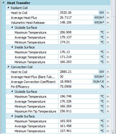
11 Page10 Figure 2: Fired Heater Inputs. Figure 3: Fired Heater Results.
12 Page11 Summary Using Flownex, the design and sizing of the fired heater, combustion air fan and the associated piping and ducting could be performed within an hour. Furthermore, results such as process temperatures, tube wall temperatures, heat fluxes, flow velocities, pressure losses etc. could easily be obtained from the network. As an overall package sizing and design tool, Flownex has proven to be far more efficient than other detailed design software. Case Study Flownex Model Availability The Flownex model discussed in this case study is available in the user project downloads area located at:
Amec Foster Wheeler- Fired Heater Division
 Amec Foster Wheeler 2016 Amec Foster Wheeler- Fired Heater Division Amec Foster Wheeler 2016 Amec Foster Wheeler Delayed Coker Heater - Best Practices Patrick Bernhagen Director of Sales Agenda 1. Overview
HOW TO BOOST THE PERFORMANCE OF FIRED HEATERS
 Originally appeared in: November 1989 issue, pgs 239-244 CHEMICAL ENGINEERING Reprinted with publisher s permission. HOW TO BOOST THE PERFORMANCE OF FIRED HEATERS Selective revamping can hike thermal efficiency
LOW-NOX BURNER RETROFIT CHALLENGE
 LOW-NOX BURNER RETROFIT CHALLENGE By Craig Lieb Applications Engineer Zeeco, Inc. Rutland, UK Ryan Roberts Project Engineering Manager Zeeco, Inc. Broken Arrow, OK, U.S.A. Ryan Roberts has more than 20
Mechanical Engineering Department Sheet (1)
") Benha University Heat and Mass Transfer Faculty of Engineering at Shoubra 3 rd Year (Power) Mechanical Engineering Department Sheet (1) (1) What is heat exchanger? Mention with brief description and sketches
Benha University Heat and Mass Transfer Faculty of Engineering at Shoubra 3 rd Year (Power) Mechanical Engineering Department Sheet (1) (1) What is heat exchanger? Mention with brief description and sketches
Shell Martinez Refinery Callidus CUBL Burners
 High Heat Density Applications of Next Generation Ultra Low NO X Burners Shell Martinez Refinery Callidus CUBL Burners Galen Coupe Shell Global Solutions Kurt Kraus - Callidus Technologies F-53 Low NOX
Module 3: Liquid Fossil Fuel (Petroleum) Lecture 25: Refinery Equipments
 Lecture 25: Refinery Equipments") 1 P age Module 3: Liquid Fossil Fuel (Petroleum) Lecture 25: Refinery Equipments 2 P age Keywords: Pipe still heater, heat exchangers, distillation tower, pumps Refinery equipments Introduction In refinery,
1 P age Module 3: Liquid Fossil Fuel (Petroleum) Lecture 25: Refinery Equipments 2 P age Keywords: Pipe still heater, heat exchangers, distillation tower, pumps Refinery equipments Introduction In refinery,
There are two devices used together for heating crude oil in petroleum refinery as in figure (1), and these devices are:
, and these devices are:") Heating of Crude Oil 1.Introduction: There are two devices used together for heating crude oil in petroleum refinery as in figure (1), and these devices are: Heat Exchangers. Tube Still Heaters (Furnaces).
Heating of Crude Oil 1.Introduction: There are two devices used together for heating crude oil in petroleum refinery as in figure (1), and these devices are: Heat Exchangers. Tube Still Heaters (Furnaces).
Coker Heaters Performance Improvement. Don Tran LyondellBasell, Houston Refinery & Ashutosh Garg Furnace Improvements Sugar Land, TX
 Coker Heaters Performance Improvement Don Tran LyondellBasell, Houston Refinery & Ashutosh Garg Furnace Improvements Sugar Land, TX Coker Heaters Most critical heaters in the refineries Heart of Delayed
HYDROCARBONENGINEERING June June 2015
 www.hydrocarbonengineering.com Controlled Combustion Arthur Groenbos, Yokogawa Europe, discusses tunable diode laser gas analysis for combustion management in fired heaters. While fired heaters are used
An experimental study of the impact of tunnel suppression on tunnel ventilation
 An experimental study of the impact of tunnel suppression on tunnel ventilation Yoon J. Ko and George Hadjisophocleous Civil and Environmental Engineering, Carleton University 1125 Colonel By Drive, Ottawa,
Fike set out to develop a better understanding of the power density trends in data centers around the world.
 Fike set out to develop a better understanding of the power density trends in data centers around the world. We wanted to learn how increasing power density translates into energy augmented combustion.
Optimisation of cooling coil performance during operation stage for improved humidity control
 Indoor Air 2008, 17-22 August 2008, Copenhagen, Denmark - Paper ID: 741 Optimisation of cooling coil performance during operation stage for improved humidity control S.C. Sekhar * and L.T. Tan National
Flameless Technology Demonstration Heater
 Environmental Conference Poster Session October 14-16, 2012 Denver Marriott City Center Denver, Colorado Flameless Technology Demonstration Heater Presented By: Taras Lewus Sage Environmental Consulting,
Gandhinagar Institute of Technology Mechanical Engineering (Thermal Engineering) Semester II. Design of Heat Exchange Equipments [ ]
![Gandhinagar Institute of Technology Mechanical Engineering (Thermal Engineering) Semester II. Design of Heat Exchange Equipments [ ]](/thumbs/78/77331028.jpg "Gandhinagar Institute of Technology Mechanical Engineering (Thermal Engineering) Semester II. Design of Heat Exchange Equipments [ ]") Experiment 1 Study of fundamentals of Fluid Flow and Heat Transfer associated with Heat Exchangers Review questions (1) Significance of dimensionless numbers. (2) Define overall heat transfer coefficient.
Experiment 1 Study of fundamentals of Fluid Flow and Heat Transfer associated with Heat Exchangers Review questions (1) Significance of dimensionless numbers. (2) Define overall heat transfer coefficient.
European Ethylene Producers Conference (EEPC) October 24-26, 2012 Flame Interaction and Rollover Solutions in Ethylene Cracking Furnaces
 October 24-26, 2012 Flame Interaction and Rollover Solutions in Ethylene Cracking Furnaces") European Ethylene Producers Conference (EEPC) October 24-26, 2012 Flame Interaction and Rollover Solutions in Ethylene Cracking Furnaces Rex K. Isaacs, Director of Burner Products, Zeeco USA, LLC Abstract
European Ethylene Producers Conference (EEPC) October 24-26, 2012 Flame Interaction and Rollover Solutions in Ethylene Cracking Furnaces Rex K. Isaacs, Director of Burner Products, Zeeco USA, LLC Abstract
KBC Petro-SIM Design Tools Integrated Equipment Operations. Al Shelton - KBC
 KBC Petro-SIM Design Tools Integrated Equipment Operations Al Shelton - KBC 2012 KBC Advanced Technologies PROPRIETARY plc. All INFORMATION Rights Reserved. July 2012 Petro-SIM Design Tools KBC has completed
Off Design Operation of Hybrid Noncondensable Gas Removal Systems for Flash Steam Cycle Geothermal Power Plants
 GRC Transactions, Vol. 40, 2016 Off Design Operation of Hybrid Noncondensable Gas Removal Systems for Flash Steam Cycle Geothermal Power Plants Jason Project Engineer, Vooner FloGard Corporation, Charlotte
DELTA-TE III. Nozzle-mix line burner
 4-21.7-1 DELTA-TE III Nozzle-mix line burner Combines excellent flexibility with extreme low emissions for direct firing Especially designed for firing in low oxygen, high humidity and/or inert process
Revamp Fired Heaters to Increase Capacity Use these guidelines to ensure a successful project
 Originally appeared in: HYDROCARBON PROCESSING June 1998 issue, pgs 67-80. Reprinted with publisher s permission. Revamp Fired Heaters to Increase Capacity Use these guidelines to ensure a successful project
High tube metal temperatures
 pcs 20/7/04 9:41 PM Page 1 Conditions influencing coke formation spots in fired heaters can lead to accelerated rates of coking and tube failure. Two examples show how integrating fireside and oil-side
"NP" & "RG" AIRFLO. In-duct firing line burner
 "NP" & "RG" AIRFLO In-duct firing line burner Duct burners - NP & RG AIRFLO 4-21.5-1 For direct fired fresh air heating applications Operates economically (100 % thermal efficiency) and installs easily
Compression of Fins pipe and simple Heat pipe Using CFD
 Compression of Fins pipe and simple Heat pipe Using CFD 1. Prof.Bhoodev Mudgal 2. Prof. Gaurav Bhadoriya (e-mail-devmudgal.mudgal@gmail.com) ABSTRACT The aim of this paper is to identify the advantages
THE WORLD S FIRST FLAMELESS CRUDE HEATER
 AFRC Industrial Combustion Symposium September 22-25, 2013 Kauai, HI THE WORLD S FIRST FLAMELESS CRUDE HEATER Authors: William C. Gibson President Marianne Zimola Sr. Process Engineer-Advanced Technologies
Refining and Petrochemical Heater trouble shooting
 Refining and Petrochemical Heater trouble shooting 16 Oil&Gas Special Report TEXT 260417.indd 16 Heater trouble shooting Refining and Petrochemical It s Getting Hot in Here! Zeeco solves the mystery of
FS 231: Final Exam (5-6-05) Part A (Closed Book): 60 points
 Part A (Closed Book): 60 points") Name: Start time: End time: FS 231: Final Exam (5-6-05) Part A (Closed Book): 60 points 1. What are the units of the following quantities? (10 points) a. Enthalpy of a refrigerant b. Dryness fraction of
Name: Start time: End time: FS 231: Final Exam (5-6-05) Part A (Closed Book): 60 points 1. What are the units of the following quantities? (10 points) a. Enthalpy of a refrigerant b. Dryness fraction of
DESIGN PHILOSOPHY. Indirect bath heaters have a wide variety of successful applications in the oil and gas
 INDIRECT HEATERS DESIGN PHILOSOPHY Indirect bath heaters have a wide variety of successful applications in the oil and gas production, processing and trasmission industry. Some of the most common application
Lanemark Midco HMA2A Series Air Heating Burner and DB Duct Burner System Application Manual
 Lanemark Midco HMA2A Series Air Heating Burner and DB Duct Burner System Application Manual HMA2A Burners DB Duct Burner Systems Contents Section 1 Section 2 Section 3 Section 4 Introduction Design Calculations
GAS CONDENSING TECHNOLOGY
 GAS CONDENSING TECHNOLOGY Authors: Ing. Dipl.-Ing. (FH) Markus Telian, Dipl.-Ing. Stefan Müller Hovalwerk AG Marketing and Development Vaduz, Principality of Liechtenstein. Abstract Hoval has realized
ZONE MODEL VERIFICATION BY ELECTRIC HEATER
 , Volume 6, Number 4, p.284-290, 2004 ZONE MODEL VERIFICATION BY ELECTRIC HEATER Y.T. Chan Department of Building Services Engineering, The Hong Kong Polytechnic University, Hong Kong, China ABSTRACT Selecting
Understanding of Surface Heat Tracing of Bulk Storage Tanks for Viscous and High Pour Point Fluids - By, H. R. Mullan
 1 of 1 UNDERSTANDING OF SURFACE HEAT TRACING OF BULK STORAGE TANKS FOR VISCOUS AND HIGH POUR POINT FLUIDS Preamble: Surface Heat Tracing for Pipes has been in use for many decades in the industry; and
ENSC 388: Engineering Thermodynamics and Heat Transfer
 ENSC 388: Engineering Thermodynamics and Heat Transfer Experiment 3: Free and Forced Convection Objective Determination of heat transfer coefficient for free and forced convection for different geometries.
Cork Institute of Technology Higher Certificate in Engineering in Building Services Engineering Award
 Cork Institute of Technology Higher Certificate in Engineering in Building Services Engineering Award Instructions Answer FIVE questions, All questions carry equal marks. (NFQ Level 6) Autumn 2006 Building
Beneficial Use of Landfill Gas for Leachate Evaporation and Power Generation
 Beneficial Use of Landfill Gas for Leachate Evaporation and Power Generation Efficient use of Energy Turning waste to energy, liabilities to assets and visions into reality. Table of Contents BENEFICIAL
Basic Input Data Needed to Develop a High Performance Fan/Blower with Low Noise, Energy Saving and High Efficiency
 Basic Input Data Needed to Develop a High Performance Fan/Blower with Low Noise, Energy Saving and High Efficiency Haiye Lou TurboMoni Applied Dynamics Lab Abstract It is often happened, when a project
Trends for Radiant Tube Heated Strip Lines
 WS Thermal Process Technology Inc., Elyria, Ohio WS Thermal Process Technology Inc., Elyria, Ohio Abstract WS Thermal Process Technology Inc., Elyria, Ohio Introduction After a extended period of low and
Efficient Steam System Design
 Efficient Steam System Design The word Efficient is often used to describe the general performance of a system. However it is important to distinguish between efficiency and effectiveness. Efficiency is
Importance of a Draught Regulator
 Importance of a Draught Regulator The purpose of a chimney (stack) is to generate a draught (draft) that will transport smoke and fumes away from the point of combustion. The chimney design and arrangement
COLD STORAGE WAREHOUSE, USING DIRECT EXPANSION AMMONIA REFRIGERANT Ray Clarke ISECO Consulting Services Pty Ltd
 COLD STORAGE WAREHOUSE, USING DIRECT EXPANSION AMMONIA REFRIGERANT Ray Clarke ISECO Consulting Services Pty Ltd Abstract This paper presents the design approach adopted for the expansion of a large existing
Reference to the Smoke Damage Index (SDI) is needed as it is part of the test method.
 is needed as it is part of the test method.") Public Input No. 4-NFPA 287-2014 [ Section No. 1.2.3.2 ] 1.2.3.2 Indices resulting from the test methods include critical heat flux (CHF), thermal response parameter (TRP), fire propagation index (FPI),
Public Input No. 4-NFPA 287-2014 [ Section No. 1.2.3.2 ] 1.2.3.2 Indices resulting from the test methods include critical heat flux (CHF), thermal response parameter (TRP), fire propagation index (FPI),
Press Release. How can the efficiency of the dryer section be increased? Dryer Section All Paper Grades. Heimbach wherever paper is made.
 Dryer Section All Paper Grades Press Release How can the efficiency of the T. Bock (Dipl.-Ing.), Manager Application & Technical Service, Heimbach GmbH & Co. KG, thomas.bock@heimbach.com I. Durniok (Dipl.-Ing.),
I] WHAT IS INFRARED? SW C FMW C MW C LW- upto 650 C
![I] WHAT IS INFRARED? SW C FMW C MW C LW- upto 650 C](/thumbs/90/101826034.jpg "I] WHAT IS INFRARED? SW C FMW C MW C LW- upto 650 C") I] WHAT IS INFRARED? Infrared (IR) is a part of electromagnetic spectrum and lies just beyond red color of visible light. Infrared is invisible. However it has properties similar to light i.e. it travels
I] WHAT IS INFRARED? Infrared (IR) is a part of electromagnetic spectrum and lies just beyond red color of visible light. Infrared is invisible. However it has properties similar to light i.e. it travels
ECLIPSE AIR HEAT BURNERS Series AH, DAH, TAH & CAH
 ECLIPSE AIR HEAT BURNERS Series AH, DAH, TAH & CAH U.S. Reissue Pat. No. 26,244 Canadian Pat. No. 743,782 Spec 140 11/4/03 AH, Front View Data 140-1 AH, Back View Data 140-1 TAH Data 140-3 DAH, Blower
Smoke Layer Height and Heat Flow through a Door
 Smoke Layer Height and Heat Flow through a Door 2018 Smoke Layer Height and Heat Flow through a Door In this tutorial you will simulate a growing fire in the corner of a 5m x 5m room. The room has a 1m
Optimization of Hybrid Noncondensable Gas Removal System for a Flash Steam Geothermal Power Plant
 GRC Transactions, Vol. 38, 2014 Optimization of Hybrid Noncondensable Gas Removal System for a Flash Steam Geothermal Power Plant J. Chip Richardson 1, P. E., and Jason Devinney 2 1 Engineering Manager,
Seyedeh Sepideh Ghaffari 1 & Seyed Ali Jazayeri 2
 Modern Applied Science; Vol. 9, No. 13; 2015 ISSN 1913-1844 E-ISSN 1913-1852 Published by Canadian Center of Science and Education The Design of a Shell-Tube Heat Exchanger as Evaporator an Absorption
The following report is prepared and published by:
 The following report is prepared and published by: Josh Dennis, Thermal Process Engineer josh.dennis@readingthermal.com of 7 CORPORATE BLVD.SINKING SPRING, PA 19608 USA T: 610-678-5890 F: 610-693-6262
Optimized Finned Heat Sinks for Natural Convection Cooling of Outdoor Electronics
 Journal of Electronics and Information Science (2018) 3: 22-33 Clausius Scientific Press, Canada Optimized Finned Heat Sinks for Natural Convection Cooling of Outdoor Electronics Lian-Tuu Yeh, ASME Fellow
The World s First Flameless Crude Heater
 The World s First Flameless Crude Heater Paper #32895 William C. Gibson, P.E., Marianne Zimola, P.E. Great Southern Flameless, LLC, 2700 N. Hemlock Ct., Suite 100, Broken Arrow, OK 74012 ABSTRACT By June
V-Line. Nozzle-mix line burner
 V-Line Nozzle-mix line burner Duct Burners - V-Line 4-22.5-1 Nozzle-mixing line burner for use with low pressure natural gas, propane and butane. Suitable for operation in variable process air-flows. Stainless
Finned Heat Sinks for Cooling Outdoor Electronics under Natural Convection
 Finned s for Cooling Outdoor Electronics under Natural Convection Lian-Tuu Yeh, Ph D & PE Thermal Consultant, Dallas, TX, 75252 USA Abstract For tower or poled mounted electronics, the heat sink weight
Tune-Rite Software Operation Manual
 Software Operation Manual P/N: 0024-9504 Revision 0 July 2014 Product Leadership Training Service Reliability Table of Contents SECTION 1. INTRODUCTION... 3 SECTION 2. SAFETY... 4 2.1. Conventions... 4
ME 410 MECHA ICAL E GI EERI G SYSTEMS LABORATORY
 ME 410 MECHA ICAL E GI EERI G SYSTEMS LABORATORY MASS & E ERGY BALA CES I PSYCHROMETRIC PROCESSES EXPERIME T 3 1. OBJECTIVE The object of this experiment is to observe four basic psychrometric processes
 Design Based Comparative Study of Several Condensers Komal B. Dabhi 1, Prof. S. B. Thakore 2 1 Chemical Engg. Dept., L. D. College of Engineering, Ahmedabad 380015 2 Chemical Engg. Dept., L. D. College
Waste/Multi Oil Boilers from Flexiheat
 Waste/Multi Oil Boilers from Flexiheat At a time of rising fuel costs, the Flexiheat FMOB universal/waste oil boiler range, which can burn nearly all vegetable, animal, conventional and waste oil, will
Boiler Basics. Design and operation
 Boiler Basics Design and operation A boiler is an enclosed vessel that provides a means for combustion heat to be transferred into water until it becomes heated water or steam. The hot water or steam under
Jurnal UMP Social Sciences and Technology Management Vol. 3, Issue. 3,2015
 The Design of a Heat Exchanger Shell - Tube as Evaporator an Absorption Chiller Cycle to Reduce the Temperature of the Air Entering Diesel Engine Heavy Loads 75% And 50% of the Engine Part Seyyede Sepideh
ecodry Figure 1 - Process Diagram ecodry B General Process Description
 ecodry The process principal of the ecodry system is centered around the concept of drying in a closed steam loop, with a process-integrated thermal oxidation. The separation of flue gas from the drying
Condensing Hydronic Boilers 2,000,000-6,000,000 BTU/HR
 Condensing Hydronic Boilers 2,000,000-6,000,000 BTU/HR The heat transfer innovators. FEATURES High Mass and Water Volume Ultra High Efficiencies Linkageless Modulation Rugged, Robust, Reliable Duplex Alloy
Heating with Wood. Part 2
 Heating with Wood Part 2 Advanced Combustion Woodburning FIREPLACE Advanced Combustion Woodburning Fireplace Fireplace & Woodstove Emissions 50 45 40 35 30 25 20 15 10 5 0 Conventional Fireplace Dirty
Scientific Principals and Analytical Model. Charcoal Cooler. Lisa Crofoot MECH 425, Queens University
 Scientific Principals and Analytical Model Charcoal Cooler Lisa Crofoot MECH 425, Queens University 1.0 Scientific Principles Evaporative cooling is based on the principle that water requires heat energy
Series LV AIRFLO. In-duct firing line burner
 Series LV AIRFLO In-duct firing line burner Duct burners - LV AIRFLO 4-21.4-1 Series LV AIRFLO burners provide stable, efficient, raw gas operations in air streams with relatively low duct velocities.
WHAT IS A BOILER? BOILER IS AN EQUIPMENT WHICH PRODUCES STEAM AT THE REQUIRED PRESSURE AND TEMPERATURE. BOILER DESIGN, MANUFACTURE & INSTALLATION ARE
 Your Logo Here TRAINING ON BOILERS PRESENTED AT M/S. MAGADI SODA COMPANY, MAGADI, KENYA LIMITED 1 WHAT IS A BOILER? BOILER IS AN EQUIPMENT WHICH PRODUCES STEAM AT THE REQUIRED PRESSURE AND TEMPERATURE.
A CEILING CONDENSING UNIT WITH PELTIER ELEMENTS FOR DRYING AND COOLING
 A CEILING CONDENSING UNIT WITH PELTIER ELEMENTS FOR DRYING AND COOLING G. COURRET, P. W. EGOLF, O. SARI Haute école spécialisée de Suisse occidentale, Institut de Génie Thermique, Rte de Cheseaux 1, CH
Improving Fired Heaters Reliability using Inclined Firing Technology
 Improving Fired Heaters Reliability using Inclined Firing Technology 1 Operating and Reliability Issues High tube metal temperatures Localized flame impingement Fired heaters have burners that are fired
Numerical Stability Analysis of a Natural Circulation Steam Generator with a Non-uniform Heating Profile over the tube length
 Numerical Stability Analysis of a Natural Circulation Steam Generator with a Non-uniform Heating Profile over the tube length HEIMO WALTER Institute for Thermodynamics and Energy Conversion Vienna University
ME 410 MECHANICAL ENGINEERING SYSTEMS LABORATORY MASS & ENERGY BALANCES IN PSYCHROMETRIC PROCESSES EXPERIMENT 3
 ME 410 MECHANICAL ENGINEERING SYSTEMS LABORATORY MASS & ENERGY BALANCES IN PSYCHROMETRIC PROCESSES EXPERIMENT 3 1. OBJECTIVE The objective of this experiment is to observe four basic psychrometric processes
2. CURRICULUM. Sl. No.
 . CURRICULUM Sl. No. Code Title No. of Lecture Hours 1 RAC 001 Fundamentals of Refrigeration and Air 60 conditioning RAC 00 Psychrometry, Heat load Estimation for 70 Air conditioning and Refrigeration
Installation of a Brunner fireplace. General Indications
 Installation of a Brunner fireplace General Indications CONTENTS 1 Basic informations...3 2 Safety precautions...4 3 Combustion air...5 4 Requirements for location... 6 5 Overview of fire safety and heat
REVIEW OF TECHNICAL STANDARDS AND CALCULATION METHODS FOR DIMENSIONING OF SMOKE AND HEAT CONTROL SYSTEMS IN CASE OF FIRE IN UNDERGROUND CAR PARKS
 REVIEW OF TECHNICAL STANDARDS AND CALCULATION METHODS FOR DIMENSIONING OF SMOKE AND HEAT CONTROL SYSTEMS IN CASE OF FIRE IN UNDERGROUND CAR PARKS Nikola TANASIĆ, Tomislav SIMONOVIĆ, Miloš IVOŠEVIĆ, Branislav
1.0 INTRODUCTION. Shaw Industries Group 2 SwRI Project No c
 1.0 INTRODUCTION This report presents the results of a fire performance evaluation in accordance with the 2011 Edition of National Fire Protection Association (NFPA) Standard 265, Standard Methods of Fire
State of the Art. Exceptional Reliability
 State of the Art The SKG 3000 uses the most advanced, commercially available gas technology ensuring consistent and efficient combustion. The same technology self-adjusts for altitude compensation and
High Performance Diesel Fueled Cabin Heater. Abstract
 High Performance Diesel Fueled Cabin Heater Tom Butcher and James Wegrzyn Energy Science and Technology Division Building 526 Upton, N.Y. 11973 Brookhaven National Laboratory Abstract Recent DOE-OHVT studies
ENERGY RECOVERY SOLUTIONS. Recover wasted energy to increase efficiency and save money immediately.
 ENERGY RECOVERY SOLUTIONS Recover wasted energy to increase efficiency and save money immediately. Cleaver-Brooks Engineered Boiler Systems Manufacturers of HRSGs, Waste Heat Recovery Units, and Waste
Effect of Modification in Refrigerant Passage of an Automotive Air Conditioning Compressor
 Purdue University Purdue e-pubs International Compressor Engineering Conference School of Mechanical Engineering 2006 Effect of Modification in Refrigerant Passage of an Automotive Air Conditioning Compressor
CATALYTIC EMITTER - An old idea in new clothes
 Page: 1 CATALYTIC EMITTER - An old idea in new clothes 1. Physical Basis There are three kinds to transfer heat: conduction, convection and radiation. In case of conduction the heat is transferred from
Boiler Technical Specifications (2013)
") ACT Bioenergy Boiler Dimensions 0.5-0.85 Million Btu/h (150-250kW) Model CP500 CP600 CP750 CP850 Heat Output in MBtu/h (kw) 510 (150) 610 (180) 750 (220) 850 (250) Height ft (mm) 6 1 (1855) 6 1 (1855)
ACT Bioenergy Boiler Dimensions 0.5-0.85 Million Btu/h (150-250kW) Model CP500 CP600 CP750 CP850 Heat Output in MBtu/h (kw) 510 (150) 610 (180) 750 (220) 850 (250) Height ft (mm) 6 1 (1855) 6 1 (1855)
THERMAX Efficiency Monitor
 INSTALLATION & OPERATION INSTRUCTIONS THERMAX Efficiency Monitor Oil & Gas Fired Heating Equipment Efficiency Monitoring Instrument Important Safety Instructions Read and safe these instructions before
DESIGN CONSIDERATIONS WHEN USING HEAT PIPES
 SEPTEMBER 2016 electronics-cooling.com DESIGN CONSIDERATIONS WHEN USING HEAT PIPES Pluggable Optics Modules - Thermal Specifications: Part 2 Comparison of Heatsinks Used for the Thermal Management of LEDs
Study and Design Considerations of HRSG Evaporators in Fast Start Combined Cycle Plants. Govind Rengarajan, P.E.CEM, Dan Taylor
 Study and Design Considerations of HRSG Evaporators in Fast Start Combined Cycle Plants Govind Rengarajan, P.E.CEM, Dan Taylor CMI Energy, Erie PA 1651 Bernd Pankow P.E, Pankow Engineering Abstract Combined
REGENERATION GAS HEATING: How It Works and What You Should Know
 REGENERATION GAS HEATING: How It Works and What You Should Know WRITERS INFO: Regeneration Gas Heating: How It Works and What You Should Know Jeff Ackel Sigma Thermal, Inc. CEO sigmathermal.com Q Zane
Thermal Fluid Heaters
 Thermal Fluid Heaters Vertical Coil, Vertical Tubeless, Electric and Horizontal Sizes from 75,000 to 40,000,000 BTU/HR The heat transfer innovators. THERMAL FLUID FEATURES AND BENEFITS KEY FEATURES No
Analysis of freeze protection methods for recuperators used in energy recovery from exhaust air
 Analysis of freeze protection methods for recuperators used in energy recovery from exhaust air Anna Pacak 1,*, Andrzej Jedlikowski 1, Demis Pandelidis 1, and Sergey Anisimov 1 1 Wrocław University of
HEAT EXCHANGERS. Heat exchangers are broadly classified based on the following considerations.
 HEAT EXCHANGERS INTRODUCTION The devices that are used to facilitate heat transfer between two or more fluids at different temperatures are known as heat exchangers. Different types and sizes of heat exchangers
ISO/TR TECHNICAL REPORT. Reaction-to-fire tests Full-scale room tests for surface products Part 2: Technical background and guidance
 TECHNICAL REPORT ISO/TR 9705-2 First edition 2001-05-01 Reaction-to-fire tests Full-scale room tests for surface products Part 2: Technical background and guidance Essais de réaction au feu Essais dans
Heat Exchanger. The purpose may be either to remove heat from a fluid or to add heat to a fluid.
 HEAT EXCHANGERS Heat Exchanger Heat exchanger is an apparatus or an equipment in which the process of heating or cooling occurs. The heat is transferred from one fluid being heated to another fluid being
CHAPTER 7 COMPARISON OF HEAT EXCHANGERS
 168 CHAPTER 7 COMPARISON OF HEAT EXCHANGERS Heat exchangers may be classified according to their flow arrangement. In parallel flow heat exchangers, the two fluids enter the exchanger at the same end,
Conductive Heating Technologies for Medical Diagnostic Equipment. Russell Strehlow, Manager of Research and Development, Minco
 Conductive Heating Technologies for Medical Diagnostic Equipment Russell Strehlow, Manager of Research and Development, Minco Table of Contents Abstract.............................................................................
CO 2 EVAPORATOR DESIGN
 By Bruce I. Nelson, P.E., President, Colmac Coil Manufacturing, Inc. CO 2 EVAPORATOR DESIGN Introduction The process of selecting air cooling evaporators to operate in a CO 2 refrigeration system is very
Euron. Compact Wall Mounted Gas Fired Condensing Boilers and Combis with Outputs 24kW - 30kW BOILERS
 Euron Compact Wall Mounted as Fired Condensing Boilers and Combis with Outputs 24kW - 30kW BOILERS Compact, Efficient & Easy to Install & Maintain The Euron range of wall mounted gas fired condensing boilers
VPC Gas Cabinet Heater Range
 VPC Gas Cabinet Heater Range Industrial & Commercial Heating Systems. www.powrmatic.co.uk HEATING // VENTIATION // AIR CONDITIONING // OEM PRODUCTS VPC Overview Models Available VPC UF - Upright Freeblowing
THE GATE COACH All Rights Reserved 28, Jia Sarai N.Delhi-16, ,-9998
 1 P a g e 1 BASIC CONCEPTS IN HEAT TRANSFER Introduction 3 Thermodynamics vs Heat transfer 4 Essential conditions for heat transfer 4 Heat transfer mechanism 4 Thermal conductivity 7 2 CONDUCTION Steady
INFLUENCE OF SOLAR RADIATION AND VENTILATION CONDITIONS ON HEAT BALANCE AND THERMAL COMFORT CONDITIONS IN LIVING-ROOMS
 INFLUENCE OF SOLAR RADIATION AND VENTILATION CONDITIONS ON HEAT BALANCE AND THERMAL COMFORT CONDITIONS IN LIVING-ROOMS Staņislavs GENDELIS, Andris JAKOVIČS Laboratory for mathematical modelling of environmental
ASSESSMENT OF FIRE BEHAVIOUR OF TIMBER PARTITION MATERIALS WITH A ROOM CALORIMETER
 , Volume 9, Number 1, p.38-58, 2007 ASSESSMENT OF FIRE BEHAVIOUR OF TIMBER PARTITION MATERIALS WITH A ROOM CALORIMETER C.W. Leung and W.K. Chow Department of Building Services Engineering, The Hong Kong
Burners Flares Incinerators Vapor Combustion
 Burners Flares Incinerators Vapor Combustion Lower Emissions & Improve Equipment Life AIChE May 20 th, 2005 Scott D. Reed 2 Heater Components Stack & Damper Convection Section Radiant Section Burners Burner
Adding More Fan Power Can Be a Good Thing
 This article was published in ASHE Journal, May 14. Copyright 14 ASHE. Posted at www.ashrae.org. This article may not be copied and/or distributed electronically or in paper form without permission of
DIRECTIVE NO: D-B
 DIRECTIVE NO: D-B6 100604 1 LOW PRESSURE THERMAL FLUID PLANT AUTOMATED CONTROL SYSTEMS Date of Issue: June 4, 2010 General Details This directive is being issued to owners, licensed contractors, consulting
Products & Services. DISTRIBUTOR & FOREHEARTH SYSTEMS
 Products & Services DISTRIBUTOR & FOREHEARTH SYSTEMS ZEDTEC design, manufacture, install and commission working ends and forehearths for the worldwide glass industry. ZEDTEC s unique designs include the
Packaged Marine Design Thermal Fluid (Hot Oil) Heaters
 Heaters") PACKAGED MARINE THERMAL FLUID (HOT OIL) HEATERS Packaged Marine Design Thermal Fluid (Hot Oil) Heaters For Heating Asphalt Barges, Tankers, And Any Other Application Requiring Dependable Heating 13 Models
PACKAGED MARINE THERMAL FLUID (HOT OIL) HEATERS Packaged Marine Design Thermal Fluid (Hot Oil) Heaters For Heating Asphalt Barges, Tankers, And Any Other Application Requiring Dependable Heating 13 Models
Experimental Study on Compact Heat Pump System for Clothes Drying Using CO 2 as a Refrigerant. Abstract
 Experimental Study on Compact Heat Pump System for Clothes Drying Using CO 2 as a Refrigerant M. Honma, T. Tamura, Y. Yakumaru and F. Nishiwaki Matsushita Electric Industrial Co., Ltd. Living Environment
HEATEC PRODUCTS AND SERVICES FOR THE FOOD INDUSTRY
 HEATEC PRODUCTS AND SERVICES FOR THE FOOD INDUSTRY WELCOME TO HEATEC About Heatec Our offices and manufacturing facility are located in Chattanooga, Tennessee. Astec Industries bought the company in 1977