AirUnit. Installation instructions. mfh systems modern floor heating. Decentralised domestic ventilation
|
|
|
- Darleen Hines
- 6 years ago
- Views:
Transcription


1 mfh systems modern floor heating AirUnit Decentralised domestic ventilation Installation instructions


2 List of contents, Installation instructions Page 1. General information Function / planning information Delivery units / scope of delivery Dimensions / technical data Selection of the installation location Installation of wall duct Installation of AirUnit controller Electrical connection Completed installation / function check Symbols The following symbols are used in the manual for labelling particular information: General information / information Warning information Information: Hazard due to electrical voltage Installation / maintenance information 02
3 1. General information The AirUnit and controller are constructed according to state of the art technology and the recognised safety regulations. Installation and maintenance work of the ventilation unit may only be implemented by trained specialist personnel under compliance with the regulations for occupational safety and accident prevention. The electrical connection must be implemented according to VDE For installation and maintenance work, disconnection from the mains at all poles with at least a 3 mm contact opening width must be undertaken. The mains disconnection is to be secured against re-connection! Use of this device is only permitted for the intended use. Incorrect usage, defectively implemented installation or maintenance work and design changes can impair the function and safety of the ventilation unit and lead to the termination of any warranty claims. Prior to beginning installation / maintenance work, read this manual carefully and observe the information provided for installation and maintenance. Prior to the installation of the device, check the delivery with regard to completeness and integrity, and in case of missing or damaged parts contact your supplier directly. Intended use AirUnit with heat recovery are designed for controlled room ventilation. The devices may only be used exclusively for the conveyance of air. The conveyance of aggressive, flammable or extremely dusty media is not permissible. Never operate the device without the filter which is inserted in the device. The connection of ventilation ducts is not permissible. AirUnits are not suitable for construction drying; operation of the device should only be implemented after completion of the construction activity. The operation of the device in connection with fireplaces possibly requires additional safety equipment (Feuerungsverordnung FeuV - German Fire Code Ordinance). Corresponding information can be obtained from the chimney sweep responsible for your region. Device location AirUnits may only be installed and operated indoors. When selecting the location for the device, take into consideration that the ventilation unit is accessible for inspection and maintenance work. Installation of the device in close proximity to flammable liquids or gases is not permissible. A mains connection (230 V / 50 Hz) is required to the controller for operation of the device. Installation For the installation of the AirUnits, the recognised rules of engineering (ARdT) are to be observed with regard to device installation, electrical work, fire protection etc. and the specifications for the ventilation of living spaces (DIN ). 03
4 2. Function The AirUnit is a decentralised ventilation system for the control of room ventilation with heat recovery. The use of several devices in pairs makes the ventilation of complete residential units / building possible. For operation with heat recovery, the ventilation unit works in 2 time intervals. In the first interval (exhaust phase) the air in the room is led outside via the exhaust operation of the ventilator. In this process, the air flows through the ceramic heat accumulator contained inside the ventilation unit and is heated. In the second interval (air feed phase), the ventilation unit is inverted and fresh external air is led into the room via the ventilation unit. In this process, the air flows through the heat accumulator, which emits the previously stored heat to the air. In this way, heat recovery of up to 90% is achieved. The principle of loading and unloading a heat accumulator is designated as being regenerative. With the operation of a single device, a positive pressure (air feed phase) or a negative pressure (exhaust phase) is created in the room to be ventilated, depending on the operational phase. In order to ensure a balanced ratio between feed and exhaust air volumes, use of the AirUnit devices in pairs is recommended. The controller enables joint operation of up to three device pairs. 2.1 Planning information Prior to the installation of AirUnits, a ventilation concept should be created in which the number of AirUnits, their installation location, the ventilation principle (cross-ventilation, single-room ventilation) and the position / number of the associated controller can be found. AirUnits enable the following ventilation variants: The ventilation of a room using a AirUnit, in intervals changing between feed / exhaust air mode with heat recovery, alternately feed* or exhaust air mode* (* depending on the electrical connection, see Page 10). The ventilation of a room or a utility unit using ventilation units operated in pairs, in intervals switching between feed / exhaust air operation with heat recovery (whilst one device of a device pair operates in feed mode the assigned second device operates in exhaust mode; the air direction of both devices alternates in the next interval), alternately feed* or exhaust air mode* (* depending on the electrical connection, see Page 10). AirUnits should be operated in pairs if possible (see Function). The device pairs can be used either in one room or also for groups of rooms. Within an utility unit, an arrangement across different storeys is also possible. An air flow between the rooms to be ventilated must be enabled through sufficiently dimensioned overflow openings (e.g. door air grids or shortened doors). As a result, odour transfer into other rooms does not occur through the air blown in (feed phase ventilation unit); for the ventilation of kitchens, bathrooms or toilets with windows, two anti-cyclically operating devices should always be installed. In inner, windowless kitchens, bathroom and toilets, AirUnit devices may not be used, as connection of the device to a duct or pipe is not permissible. The use of an exhaust ventilator is recommended in this case acc. DIN T.3. Likewise, device installations in cellar rooms with light shafts is not possible, as recirculation of the exhaust air cannot be excluded. In order to prevent recirculation with the facade installation of devices, a minimum distance of 1.0 m should be maintained between the single devices. In case the building location is exposed to the wind (medium wind speed > 5 m/s), we recommend that you do not use this device. In order to prevent draft occurrence through the operation of the ventilation units, the devices should not be placed directly in areas where people stay for prolonged lengths of time (seating areas, beds). Ensure that the air flow in the room is not impaired by furniture or curtains. 04
, ceramic heat accumulator for heat recovery, a filter (G3) and sealing rings which are inserted into a wire assembly incl.")
5 3. Delivery units / scope of delivery A complete AirUnit comprises of a NEOPOR wall duct and a ventilator unit inserted into the wall duct. The ventilator unit comprises of a reversible ventilator (12 V/DC), ceramic heat accumulator for heat recovery, a filter (G3) and sealing rings which are inserted into a wire assembly incl. protection grid and enclosed by a housing pipe. Furthermore, all ventilation units are delivered with an additional sound insulation mat. The air flow in the room takes place via a closable and sound-insulated design screen. The exterior air flow occurs via a weather protection hood. The operation of the device occurs via the controller with operating panel (accessory). Up to six AirUnits (3 x feed 3 x exhaust) can be controlled via the controller. The installation of the controller occurs in a device double socket, e.g. flush-mounted, double cavity wall socket. The following delivery units are available: AirUnit 500: Ventilation unit with wall duct 495 mm, ventilator unit, interior design screen (RAL 9016) and weather protection hood (RAL 9016). AirUnit 500 stainless steel: Ventilation unit with wall duct 495 mm, ventilator unit, interior design screen (RAL 9016) and weather protection screen made from stainless steel. AirUnit 1000: Ventilation unit with wall duct 1000 mm, ventilator unit, interior design screen (RAL 9016) and weather protection screen (RAL 9016). AirUnit 1000 stainless steel: Ventilation unit with wall duct 1000 mm, ventilator unit, interior design screen (RAL 9016) and weather protection screen made from stainless steel. Controller: For up to 6 AirUnits (3x feed, 3x exhaust) incl. cover frame Filter (G3) 2 Ceramic heat accumulators for heat recovery 3 Ventilator (12 V/DC) 4 Sound insulation mat 5 Exterior hood (weather protection screen in RAL 9016 or stainless steel) 6 Sealing ring (heat accumulator) 7 Housing pipe 8 Sealing ring (ventilator) 9 Wire assembly incl. protection grid 10 Wall duct (495 or 1000 mm) 11 Interior design screen 05


6 4. Dimensions AirUnit (all dimension information in mm) 11mm alternatively 1, AirUnit interior screen 4.1 Technical data Controller 223 AirUnit weather protection screen AirUnit Air output m³/h Degree of efficiency of the heat exchanger up to 90% Supply voltage 230 V/50 Hz Power consumption 0,8 1,1 1,7 2,7 W Sound pressure level (1m)* db(a) Sound pressure level (3m)* db(a) Filter category G3, regenerative Permissible operating temperature -20 bis +40 C Protection class III Weight ~ 2.5 kg ø wall duct (interior / exterior) 154 / 198 mm Length of wall duct 495 / 1000 mm * Internal measurement, average valure of exhaust and supply phase room-side Controller Operating modes Power unit Switch range Input Output Protection class Controller controller 4 performance levels (optional 3 performance levels + OFF) winter and summer mode up to 6 devices including cover frame 2 times and blank cap 230 V / 50 HZ 12 V DC 24 W IP 00 (without cover) 06


7 5. Selection of the installation location On selecting the installation location, observe the exterior view of the building. In order to harmoniously integrate the devices into the building facade, the devices should be installed at the same height / with the same distance to the windows, for example. Observe the dimensions of the exterior or room-side air passages. It is recommended that you maintain a minimum distance of 200 mm around the wall duct to the neighbouring facade components / elements and room corners! The AirUnits devices may not be covered by furniture or curtains. Recommended minimum distance for the installation of a device pair in a wall: Recommended minimum distance for the installation of a device pair across a corner: 6. Installation wall duct Wall ducts in two different lengths are available for the AirUnits: Pipe length 495 mm Pipe length 1000 mm The AirUnit is delivered with 495 mm or 1000 mm-long wall ducts, all wall ducts are manufactured with an integrated gradient to the outside for the drainage of condensate (observe the room-side labelling, see Fig. below.) Roomside below 07

 according to the room and facade.")


 of the ventilator / heat")
8 6.1 Core drill hole wall duct Prepare a core drill hole with a diameter 200 mm and create a cable slot for the connection lines. 6.2 Installation wall duct Insert the wall duct into the wall opening and leave the wall duct protruding if required (e.g. for additional plaster or insulating layers) according to the room and facade. Observe that the gradient slopes to the exterior or the room-side labelling of the wall duct. Seal the wall duct with the masonry on the interior and exterior with an appropriate sealant. For larger wall openings, the cavities between the wall opening and the wall can be filled with non-pressing installation foam. The wall duct can be trimmed flush with a carpet knife after the completion of the wall. Caution: In order to ensure tension-free installation / removal (maintenance) of the ventilator / heat accumulator in the wall duct, deformations of the wall duct through external pressure / tensions are to be avoided! Observe that the wall opening is installed with a gradient to the outside at all times. 08


 is recommended as a supply line.")
9 6.3 Wall duct insertion, ventilation unit connection pipe Insert the connection pipe (min. 3 x 0.60 mm²) laterally (room-side view) into the wall duct. Allow the connection pipe to protrude in length past the wall duct. Close the wall duct on the interior and exterior side using the supplied wall covers (see Page 14), in order to prevent contamination of the wall duct. 7. Installation controller The controller is designed for installation in a device double socket. It can be used to control up to six AirUnits. The controller is to be connected as stationary equipment with permanently laid lines. Electrical connection diagram, see page 10. The supply voltage of the controller is 230 V/50 Hz; a sheathed cable 3 x 1.5 mm² (e.g. NYM-J 3 x 1.5 mm²) is recommended as a supply line. Control of the ventilation units occurs via 12 V DC, therefore under no circumstances may the ventilation units be connected to the 230 V mains voltage of the control electronics. A sheathed cable min. 3 x 0.60 mm² is recommended as a connection line for the AirUnits. 09
10 8. Electrical connection The electrical connection must be implemented according to VDE For installation and maintenance work, disconnection from the mains on all poles with at least 3 mm contact opening width must be undertaken. The mains disconnection is to be secured against reconnection! Connection controller Device 1 PWM PURPLE Device 3 PWM PURPLE Device 5 PWM PURPLE Connection feed devices External inputs, see page 11 PWM PURPLE Device 2 PWM PURPLE Device 4 PWM PURPLE Device 6 Connection exhaust air devices The connection of several devices occurs arranged in pairs at the plug connectors device 1 - device 2, device 3 - device 4, device 5 - device 6; in paired operation one device of a device pair operates in feed mode, the second assigned device in exhaust air mode The air flow direction of both devices is alternated at intervals. The AirUnits connected to the plug connectors device 1, 3 or 5 serve as feed devices in summer mode. The AirUnits connected to the plug connectors device 2, 4 order 6 become exhaust devices in summer mode. Therefore cross-ventilation can occur with the use of several devices i.e. in order to convey cool outside air into the building during summer nights. PE N L1 Mains connection 230 V / 50 Hz With the use of a single device, the AirUnit can be used as a feed or exhaust device in summer mode. 8.1 Connection AirUnit(s) controller Ventilation device PWM PURPLE Controller RED +12 V PURPLE PWM BLUE Gnd The connection of the AirUnits to the connection line of the controller is implemented via a plug connector contained within the scope of delivery of the ventilation units, as depicted previously. Please observe the polarity feed / exhaust devices (see Fig. above)! 10
11 8.2 Electrical connection of external control elements The adjustment of operation mode on the AirUnits occurs as required by the user via the operating panel on the controller. Different operating variants with different performance levels can be selected. Through the connection of optional, external control elements, a time or humidity-dependent device operation can be additionally activated. The connection of external control elements occurs via connection plugs external inputs on the rear side of the controller as depicted below. The device function with an external control is described from Page 7 Operating manual onwards. Connection of external control elements Optional external humidity control (e.g. hygrostat) Function description, see Page 7 Operating manual H% Connection plugs, external inputs Device 5 PWM LILA PWM LILA Device 6 Optional external switch-off (e.g. time switch) Function description, see Page 7 Operating manual Connections feed devices (max. 3 pieces) Connections exhaust air devices (max. 3 pieces) PE N L1 Mains connection 230 V / 50 Hz A data line is recommended (e.g. 2 x 2 x 0.6 (z. B. J-Y(ST)Y)) for the connection of external control inputs (potential-free contacts). 11


12 9.1 Complete installation After completion of the insulation / plaster work, remove the wall covers on the interior and exterior side. Adapt the wall duct to the dimensions of the finished wall by trimming the wall duct flush with the room or facade side using a carpet knife or a hot wire. To protect against water penetration into the wall opening, the facade-side transition to the wall duct must be sealed circumferentially using a suitable sealant! Adhere the supplied sealing tape circumferentially to the rear side of the outer wall panel. Subsequently, install the wall panel to the weather protection hood using suitable attachment elements. Install the weather protection hood to the AirUnit. The hood is mounted onto the attached brackets on the upper edge of the wall panel and attached to the wall panel using the supplied attachment screws. 12

.")


, the AirUnit can be commissioned via the operating panel of the controller.")
13 Install the inner wall panel using suitable attachment elements and carefully insert the ventilator unit (ventilator faces towards the room) into the wall. Observe that in the process the connection pipe of the ventilator is not bent / damaged. The ventilator unit can be aligned above the protection grid during the installation and be pulled back out of the wall duct again for maintenance purposes. Subsequently, connect the plug connectors of the connection line to the controller (for details see Electrical connection Page 10). Circumferentially insert the sound insulation mats with a distance of min. 3 cm to the ventilator unit on the room side. Push the inner screen onto the hinge of the wall panel. The inner screen can be closed as required by means of the magnetic closures. In an open state, the inner screen is open at the top with an aperture angle of approx Function check After completion of the installation work, the function of the device has to be checked. Prior to inspection, ensure that the air passages of the ventilation unit are free from installation debris / foreign objects, and that all electrical work has been implemented and completed professionally! After switching on the power supply (normally via the automatic circuit breaker of the electrical installation), the AirUnit can be commissioned via the operating panel of the controller. During commissioning, check all the device functions described in the Operating manual from Page 6 onwards. During the inspection, check for quiet, smooth operation of the ventilator motor. Determined malfunctions or faults on the AirUnit must be rectified prior to final commissioning of the device; possible error sources and their rectification are described in the chapter Malfunctions (see Page 11 Operating manual). Document the properly-executed installation / function check of the ventilation unit(s) in the Commissioning log (separate form). 13

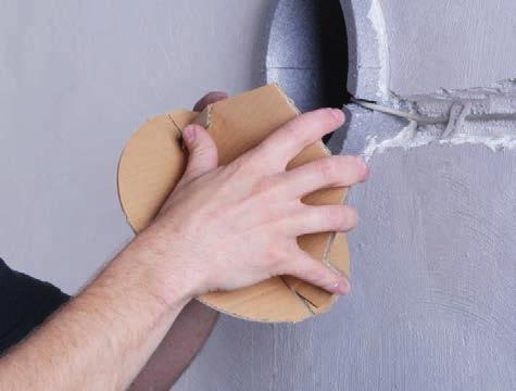
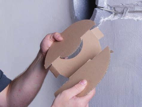
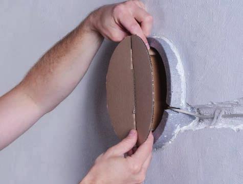
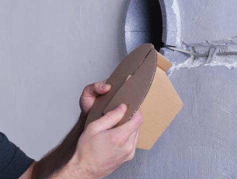
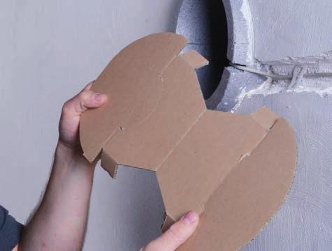
14 Wall cover folding instructions
15 15
16 mfh systems GmbH Hager Feld Belm-Vehrte Germany Fon +49 (0) Fax +49 (0) mail@mfh-systems.com
AirUnit. Operating manual. mfh systems modern floor heating. Decentralised domestic ventilation
 mfh systems modern floor heating AirUnit Decentralised domestic ventilation Operating manual List of contents, Operating manual Page 1. General information... 02 2. Device description... 03 3. Adjustment
Pluggit iconvent Decentralized residential ventilation with heat recovery Operating and installation instructions
 git iconvent Decentralized residential ventilation with heat recovery Operating and installation instructions www.pluggit.com The technology makes the difference. Innovations of git with an added value
Installation Manual Local Ventilation System with Heat Recovery Type e² and e² short
 Contents Installation Manual Local Ventilation System with Heat Recovery Type e² and e² short Page: About this manual, safety instructions 1 Technical Specifications, Disposal 1 Dimensional diagrams 2
Instructions for Operation and Maintenance of Containers
 Instructions for Operation and Maintenance of Containers Container Handling 1. Containers are designed for transport on a flat loading area that is 2.5 m wide, which enables support of the load-bearing
TTV 1500 / TTV 3000 OPERATING MANUAL CONVEYING FAN TRT-BA-TTV TC EN
 TTV 1500 / TTV 3000 EN OPERATING MANUAL CONVEYING FAN TRT-BA-TTV1500-3000-TC2016-26-004-EN Table of contents Notes regarding the operating manual... 2 You can download the current version of the operating
INDEX RECOMMENDATIONS AND SUGGESTIONS... 4 CHARACTERISTICS... 5 INSTALLATION... 6 USE... 9 MAINTENANCE... 11
 INDEX EN RECOMMENDATIONS AND SUGGESTIONS... 4 CHARACTERISTICS... 5 INSTALLATION... 6 USE... 9 MAINTENANCE... 11 2 RECOMMENDATIONS AND SUGGESTIONS The Instructions for Use apply to several versions of this
Katherm NE - Natural convection with electric heating element 2.45
 1.26 1.45 Katherm NE - Natural convection with electric heating element 2.45 Please retain this manual carefully for future use! Read carefully prior to commissioning! I 60/0/09/01 GB 2.45 Katherm NE -
THROUGH-WALL AIR-TO-AIR HEAT PUMP AND AIR CONDITIONER. Instruction Manual. Model AMB-12H
 THROUGH-WALL AIR-TO-AIR HEAT PUMP AND AIR CONDITIONER Instruction Manual Model AMB-12H PLEASE READ THIS INSTRUCTION MANUAL CAREFULLY BEFORE USING THIS UNIT. Table of Contents 1. SAFETY WARNINGS 2 2. CONSTRUCTION...
USER S MANUAL. Centrifugal inline fan. VKMz 100 Q VKMz 100 VKMz 125 Q VKMz 125. VKMz 250 Q VKMz 250 VKMz 315 Q VKMz 315
 USER S MANUAL VKMz 100 Q VKMz 100 VKMz 125 Q VKMz 125 VKMz 150 VKMz 160 VKMz 200 Q VKMz 200 VKMz 250 Q VKMz 250 VKMz 315 Q VKMz 315 Centrifugal inline fan VKMz CONTENTS Contents... 2 Safety requirements...
SINGLE-ROOM REVERSIBLE UNIT WITH HEAT AND HUMIDITY RECOVERY VENTO V50-1 OPERATION MANUAL
 SINGLE-ROOM REVERSIBLE UNIT WITH HEAT AND HUMIDITY RECOVERY VENTO V50-1 EN OPERATION MANUAL CONTENTS Introduction 3 General 3 Safety rules 3 Transportation and storage rules 3 Manufacturer's warranty 3
PRODUCT INFORMATION. Sounder SG 200. BDL F.01U A3.en / ST FIR/ PRM1 / zab. Page 1 of 10
 PRODUCT INFORMATION PI 38.43 Sounder SG 200 Page 1 of 10 Table of Contents 1. Product Description............................... 3 2. Features......................................... 3 3. Functional Description............................
EN Instruction on mounting and use
 EN Instruction on mounting and use EN - Instruction on mounting and use Closely follow the instructions set out in this manual. All responsibility, for any eventual inconveniences, damages or fires
Table of Content LT 5165-UL
 Table of Content LT 565-UL. User manual.... Legal regulations... 3. Safety instructions... 3 4. Technical information... 4 5. Technical data... 4 6. Performance Graph... 5 7. Mounting... 6 8. Mounting
IDE 20 / IDE 30 / IDE 50 IDE 60 / IDE 80
 IDE 20 / IDE 30 / IDE 50 IDE 60 / IDE 80 EN OPERATING MANUAL OIL HEATER TRT-BA-IDE20-30-50-60-80-TC-001-EN Table of contents Information on the use of this manual... 1 Scope of delivery... 1 General safety...
Hygro and Hygrothermal Transducers (Capacitive) for Air Conditioning Applications
 for Air Conditioning Applications") Data Sheet 907020 Page 1/9 Hygro and Hygrothermal Transducers (Capacitive) for Air Conditioning Applications For measuring relative humidity and temperature For versatile climatic applications and ventilation
Data Sheet 907020 Page 1/9 Hygro and Hygrothermal Transducers (Capacitive) for Air Conditioning Applications For measuring relative humidity and temperature For versatile climatic applications and ventilation
Installation manual Mini Comfort 50 S/L 07/ V EN
 Installation manual Mini Comfort 50 S/L 07/2015 - V 1.1 - EN www.veneco-ventilation.be Veneco ventilation by Elek Trends Productions nv Blauwfazantjesstraat 4 B - 7700 Moeskroen Tel. +32 (0)56 48 15 90
Silvento concealed variant clamped-ventilator - Replaces Skalar-; Skalar-V...; Skalar-2V... - Installation directions - Please pass on to the user -
 Silvento concealed variant clamped-ventilator - Replaces Skalar-; Skalar-V...; Skalar-2V... - Installation directions - Please pass on to the user - Contents: Notes on these installation instructions Safety
LEIHDC70SC - LEIHDC70BB LEIHDC70BC. Instructions Manual.
 LEIHDC70SC - LEIHDC70BB LEIHDC70BC Instructions Manual www.rangemaster.co.uk INDEX EN RECOMMENDATIONS AND SUGGESTIONS...3 CHARACTERISTICS...4 INSTALLATION...5 USE...8 MAINTENANCE...9 2 RECOMMENDATIONS
Installer manual AG-WL10
 LEK LED CLEAN TIMER OPERATION Installer manual Indoor unit air/air heat pump IHB GB 1637-1 331827 Table of Contents 1 Important information Safety information Read before starting the installation Electrical
GB Operating instructions
 Scope of delivery/device components 1 Carrier for suction nozzles 2 Dust bin 3 Release button (dust bin) 4 On/Off Switch 5 Motor casing 6 Rechargeable battery 7 Release buttons rechargeable battery 8 Swing
3-way switching valve
 Operating Manual UK 3-way switching valve for domestic hot water charging USV 1" AG USV 5/4" AG USV 6/4" IG UK805189 / 201109 Translation of the original instruction manual Please read first This operating
AIRGOCLEAN 10 E OPERATING MANUAL AIR CLEANER TRT-BA-AIRGOCLEAN10E-TC-001-EN
 AIRGOCLEAN 10 E EN OPERATING MANUAL AIR CLEANER TRT-BA-AIRGOCLEAN10E-TC-001-EN Table of contents Notes regarding the operating manual... 1 You can download the current version of the operating manual and
INSTALLATION AND USER S MANUAL COOKER HOOD RS-600/A-S
 INSTALLATION AND USER S MANUAL COOKER HOOD RS-600/A-S RS-600 (CHS60SS)-GB-05.indd 1 6/8/2010 9:30:59 AM TABLE OF CONTENTS 1. Introduction 2 2. Safety precaution 2 3. Intended use 3 4. Parts supplied 3
TEMPAIR 3 IN 1 EXHAUST FAN SKU# &
 TEMPAIR 3 IN 1 EXHAUST FAN SKU# 200290 & 200291 CAUTION READ INSTRUCTIONS CAREFULLY FOR SAFE INSTALLATION AND FAN OPERATION. WARRANTY - This product is covered by a 3 year warranty. The warranty is from
EHA Hoffmann International GmbH
 EHA Hoffmann International GmbH User manual EHA-TRANSPRINT HP 2020 Machine-No.: Year: EHA Hoffmann International GmbH Michelsbergstraße 24 D-57080 Siegen/Germany Telephone: +49 271 39 32-0 Telefax: +49
ELTSHDC110SG/ Users Guide & Installation Instructions
 ELTSHDC110SG/ Users Guide & Installation Instructions CONTENTS IMPORTANT SAFETY INFORMATION Installation Page 2 Child Safety 2 Maintenance and service 3 YOUR APPLIANCE OPERATING INSTRUCTIONS Cooker Hood
FLANGED CORR/GUARD CORR/GUARD INSTALLATION INSTRUCTIONS
 CORR/GUARD INSTALLATION INSTRUCTIONS This symbol on the nameplate means this product is listed by Underwriters Laboratories Inc. Tested to UL1738 / CAN / ULCS636-08 Listing No. MH26687 Testing No. 11EN
TDS 20 R / TDS 30 R / TDS 50 R
 TDS 20 R / TDS 30 R / TDS 50 R EN OPERATING MANUAL ELECTRICAL FAN HEATER TRT-BA-TDS20R-30R-50R-TC-001-EN Table of contents Notes regarding the operating manual... 1 Safety... 1 Information about the device...
SOUND-INSULATED FAN. Iso-K OPERATION MANUAL. Iso-K_v.1(2)-EN.indd :20:59
-EN.indd :20:59") SOUND-INSULATED FAN OPERATION MANUAL _v.1(2)-en.indd 1 10.08.2015 15:20:59 CONTENT Introduction 3 General 3 Safety rules 3 Transport and storage requirements 3 Manufacturer's warranty 3 Fan design 4 Delivery
SOUND-INSULATED FAN OPERATION MANUAL _v.1(2)-en.indd 1 10.08.2015 15:20:59 CONTENT Introduction 3 General 3 Safety rules 3 Transport and storage requirements 3 Manufacturer's warranty 3 Fan design 4 Delivery
1. Contents Principle General information Parts list Assembly Technical drawing... 18
 1. Contents 1. Contents... 2. Principle... 2 3. General information... 3-7 4. Parts list... 8 5. Assembly... 9-17 6. Technical drawing... 18 2. Principle All instructions provided with products must be
Carbon Film Installation Instructions
 Contents Page 2 Page 3 Page 4 Page 5 Page 8 Product Overview Pre-Installation & Electrical Provision Depron Underlay Installation Carbon Film Installation - Under Wood/Laminate Flooring Notes & Trouble
Atmos EasySolar. Installation Instructions for. In-roof and flat roof installation with flat plate collectors
 Atmos EasySolar Installation Instructions for Atmos EasySolar In-roof and flat roof installation with flat plate collectors Atmos Heating Systems West March Daventry Northants, NN11 4SA Tel: 01327 871990
Warnings, Safety Information and Guidance
 EN SR700 SRHRV Fan TP600 Single Room Heat Recovery Ventilation Fan Unit SRC Controller TP590 Single Room Heat Recovery Ventilation Controller Unit Product Installation Manual ventilation systems Warnings,
SINGLE-ROOM ENERGY RECOVERY VENTILATORS
 SINGLE-ROOM ENERGY RECOVERY VENTILATORS Silent operation Easy mounting Multi-purpose functioning TWINFRESH COMFO RB1-50 SINGLE-ROOM VENTILATORS EFFICIENT, RELIABLE AND ENERGY-SAVING VENTILATORS TWINFRESH
Decentralised comfort ventilation unit Zehnder ComfoSpot 50
 Application Zehnder ComfoSpot 50 is a decentralised comfort ventilation unit with heat and humidity recovery using synchronous supply or extract air operation. It is often used in apartment renovations
GUH90 90 cm Canopy Hood
 User Manual for your GUH90 90 cm Canopy Hood NOTE: This User Instruction Manual contains important information, including safety & installation points, which will enable you to get the most out of your
Ventilator insert Silvento V... Installation directions - Please pass on to the user -
 Ventilator insert Silvento V... Installation directions - Please pass on to the user - Contents: Notes on these installation instructions Safety precautions Technical specifications, waste disposal Parts
FSW300 Series Flow Switch
 . FSW300 Series Flow Switch - 2 - Series FSW300 Series FSW300 Table of contents page 0 About this operating manual... 4 1 Device description... 5 1.1 Intended use... 5 1.1.1 Reed contact - Switching of
TIH 300 S / TIH 400 S / TIH 500 S / TIH 700 S / TIH 900 S / TIH 1100 S
 TIH 300 S / TIH 400 S / TIH 500 S / TIH 700 S / TIH 900 S / TIH 1100 S EN OPERATING MANUAL INFRARED HEATING PANEL TRT-BA-TIH300S-TIH400S-TIH500S-TIH700S-TIH900S-TIH1100S-TC-002-EN Table of contents Notes
Instructions for use. Gas hobs for installation in worktops GKS GWS GKS GKS
 Instructions for use Gas hobs for installation in worktops GKS 3920.0 GWS 3911.0 GKS 6940.0 GKS 9951.0 For use in: Hong Kong Issue: 2014-01-14 Version: 1.3_EN Identity no.: 073587_HK Welcome 2 Welcome
Mechanical seals external, single or double, to DIN EN 12756
 INSTALLATION AND OPERATING MANUAL Translation of the original manual Series SCK Bearing pedestal group: 0 Mechanical seals external, single or Keep for future use! This operating manual must be strictly
Instruction Manual. Orayonne. Glass radiation heater
 Instruction Manual Orayonne Glass radiation heater Table of Contents General...19 Safety information...20 Manufacturing state, packaging and recycling...21 Installation instructions for the fitter...22
Illustration shows item no Z Original operating manual. Operating manual. BlueMobil eco. Item no: Z-3278
 Illustration shows item no Z-3278 Operating manual BlueMobil eco Item no: Z-3278 Original operating manual Important Copyright It is essential that you read this manual thoroughly before the initial operation
Operating Instructions. Accessory Units Melitta Cafina XT Series. Melitta Professional Coffee Solutions
 Operating Instructions Accessory Units Melitta Cafina XT Series Melitta Professional Coffee Solutions Contents General... 4. Manufacturer information... 4.2 About these instructions... 4.3 Explanation
Sanpress Inox G. Instructions for Use. Year built: from 02/2004 en_int
 Sanpress Inox G Instructions for Use Year built: from 02/2004 en_int Sanpress Inox G 2 from 27 Table of contents Table of contents 1 About these instructions for use 4 1.1 Target groups 4 1.2 Labelling
AZSG10000/AZSG10005/AZSG10010 ABUS Wired Outdoor Siren
 AZSG10000/AZSG10005/AZSG10010 ABUS Wired Outdoor Siren EN Installation instructions and user guide Version 1.0 Contents Introduction... 3 Safety information... 4 Scope of delivery... 5 Technical data...
Dipl.-Ing. W. Bender GmbH & Co. KG Londorfer Str Grünberg Phone: Fax:
 Dipl.-Ing. W. Bender GmbH & Co. KG Londorfer Str. 5 35305 Grünberg Phone: 040 807-0 Fax: 040 807-259 Alarm indicator and test combination MK2430 Remote alarm indicator and test combination with LC display
Handling or using the product improperly and in disregard of the instructions with this mark might result in serious bodily injury or death.
 Please Read: Safety Precautions DC AC In order to ensure that this product is used safely, be sure that you read and understand the following precautions fully and use the product only as directed. Be
Händetrockner Hand dryer Sèche-mains Handendroger Osoučeč rukou Suszarka do rąk Сушилки для рук Kézi szárító
 BEDIENUNG UND INSTALLATION OPERATION AND INSTALLATION UTILISATION ET INSTALLATION BEDIENING EN INSTALLATIE OBSLUHA A INSTALACE OBSŁUGA I INSTALACJA ОБСЛУЖИВАНИЕ И УСТАНОВКА HASZNÁLATI ÉS TELEPÍTÉSI ÚTMUTATÓ
BR342 Ducted Installation Instructions Australian Version Electronic Wall Control
 Australian Version Electronic Wall Control 1 Introduction The BR342 reverse cycle rooftop air-conditioner is designed for installation onto Recreational Vehicles (RV s) at the time of manufacture or as
Atmos EasySolar. Installation Instructions for. Sloping roof and flat roof installation with evacuated tube collector
 Atmos EasySolar Installation Instructions for Atmos EasySolar Sloping roof and flat roof installation with evacuated tube collector Atmos Heating Systems TBS Building Supplies Ltd Hackwood Road Daventry
HR200WK Through the wall Heat Recovery Ventilator
 HR200WK Through the wall Heat Recovery Ventilator Installation and Maintenance Instructions Stock Ref No:- HR200WK 14120020 PLEASE READ INSTRUCTIONS IN CONJUNCTION WITH ILLUSTRATIONS. PLEASE SAVE THESE
2CKA001473B System Manual Busch-Infoline. Handicapped toilet signal set 1510 UC
 2CKA001473B9007 19.05.2017 System Manual Busch-Infoline Handicapped toilet signal set 1510 UC-... -101 Table of contents Table of contents 1 Notes on the instruction manual... 3 2 Safety... 4 2.1 Information
IdealFILM. Do-It-Yourself Installation Manual
 IdealFILM Do-It-Yourself Installation Manual Comfortable Warm Floors Benefits of using RSG Idealfilm Heats from the floor up for better heat distribution throughout the room No dust or allergens blown
Remote alarm indicator and test combination MK2430
 Dipl.-Ing. W. Bender GmbH & Co. KG Londorfer Str. 5 35305 Grünberg Tel.: 040 807-0 Fax: 040 807-259 Remote alarm indicator and test combination MK2430 Remote alarm indicator and test combination with LC
AC THOR. Assembly Instructions
 AC THOR Photovoltaic-Power-Manager for hot water and space heating Assembly Instructions The Operation Manual of the device is available at www.my-pv.com. The following device key is required for online
C o o l i n g a n d h e a t i n g s y s t e m s
 2 C o o l i n g a n d h e a t i n g s y s t e m s Cooling ceiling system description Preliminary remarks Cooling ceilings Cooling ceilings are room cooling systems for placement in the ceiling zone. Their
INSTALLATION GUIDE ISODRIVE MOTOR. ST - 900m 3 /hr.
 INSTALLATION GUIDE ISODRIVE MOTOR ST - 900m 3 /hr www.schweigen.co.nz Welcome Thank you for purchasing your new Schweigen Isodrive system. To get the maximum output from this unit, please read through
Popcorn Warmer Cabinet
 Popcorn Warmer Cabinet Copyright July 2016 Future Products Group Limited. All rights reserved. No part of this publication may be reproduced, stored in a retrieval system, or transmitted in any form or
Installer manual AG-AA10. Air/air heat pump IHB GB AG-AA10-30 AG-AA10-40/50
 -30 Installer manual Air/air heat pump -40/50 IHB GB 1516-1 331554 Table of Contents 1 Important information 2 5 Installation 7 Safety information 2 Model combinations 7 Read before starting the installation
Operating Manual. Please keep this manual. with the unit! Cooling Unit. For Heat Recovery Unit santos (F) 570 DC. Status:
 570 DC. Status:") Cooling Unit For Heat Recovery Unit santos (F) 570 DC Operating Manual Please keep this manual with the unit! Status: 04.10 Design version: R Right (supply air) L Left (supply air) Paul Wärmerückgewinnung
Cooling Unit For Heat Recovery Unit santos (F) 570 DC Operating Manual Please keep this manual with the unit! Status: 04.10 Design version: R Right (supply air) L Left (supply air) Paul Wärmerückgewinnung
USER S MANUAL NKP. Duct heater for supply air pre-heating with external control
 USER S MANUAL Duct heater for supply air pre-heating with external control CONTENTS Contents... 2 Safety requirements... 2 Purpose... 4 Delivery set... 4 Designation key... 4 Technical data... 5 Design
VH60SS 60CM VISOR HOOD STAINLESS STEEL
 VH60SS 60CM VISOR HOOD STAINLESS STEEL INSTRUCTION MANUAL Thank you for purchasing our product. We hope you enjoy using the many features and benefits it provides. Before using this product please study
Operating manual 1 SAFETY REGULATIONS AND INFORMATION. Original operating manual INDEX. RG CPAP 24 V mit Powermodul 24V sensorless
 Operating manual RG CPAP 24 V mit Powermodul 24V sensorless 1 SAFETY REGULATIONS AND INFORMATION Read the operating manual carefully before commencing work at the product. Pay attention to the following
Bedienungsanleitung. Ideas for dental technology. Made in Germany C
 Bedienungsanleitung 216604 C 01022013 Made in Germany Ideas for dental technology GLISH Instruction manual 1. Introduction...1 1.1 Employed Symbols...1 2. Safety...2 2.1 Intended use...2 2.2 Improper use...2
IDE 20 D / IDE 30 D / IDE 50 D / IDE 60 D / IDE 100 D
 IDE 20 D / IDE 30 D / IDE 50 D / IDE 60 D / IDE 100 D EN OPERATING MANUAL OIL HEATER TRT-BA-IDE20D-30D-50D-60D-100D-TC-001-EN Table of contents Notes regarding the operating manual... 1 Safety... 2 Information
Waste water ejection unit
 Waste water ejection unit Over ground box SWH 500/50-80 SWH 500/50-80 Operation manual Table of contents: Page Declaration of conformity... 3 1. General... 4 1.1 Introduction... 4 1.2 Enquiries and orders...
Instruction manual for downdraft hood
 Instruction manual for downdraft hood Model code: BODY / DD600BK - BODY / DD900BK BODY / DD600SS - BODY / DD900SS Contact Caple on 0844 800 3830 or for spare parts www.4caple.co.uk The symbol on the product
Installation and maintenance manual
 Installation and maintenance manual Warm air heater WS/WO (Copy of the original version) Wolf GmbH D-84048 Mainburg Postfach 1380 Telefon +498751/74-0 Telefax +498751/741600 Internet: www.wolf-heiztechnik.de
Ceiling Mount Air Purification System
 Ceiling Mount Air Purification System HA-CMP-G2-R/HA-CMP-G2-OV Owner s Manual Table of Contents HealthyAir Series 1219 Filters 1 Important Safety Instructions 2 Technical Specifications 3 Packaging Reference
Fillmore Small Pendant Assembly and Installation Instructions
 CAUTION: Fillmore Small Pendant Assembly and Installation Instructions BEFORE INSTALLING FIXTURE, MAKE SURE THE POWER TO THE CIRCUIT IS TURNED OFF AT THE MAIN FUSE BOX / CIRCUIT BREAKER UTILITY BOX. Important
CHAPTER 8 CHIMNEYS AND VENTS
 CHAPTER 8 CHIMNEYS AND VENTS SECTION 801 GENERAL 801.1 Scope. This chapter shall govern the installation, maintenance, repair and approval of factory-built chimneys, chimney liners, vents and connectors.
Flow switch. Operating Manual. English manual page Page 1 of 15 Fax:
 Operating Manual www.jlso-tec-trade.de Flow switch English manual page 1-15 Page 1 of 15 Flow switch Table of Contents Page 1 Device Description and Intended Use... 19 1.1 Flow switch version VH...X...
Swegon CASA R120. Ventilation unit with rotary heat exchanger HOME VENTILATION
 Swegon CASA R120 Ventilation unit with rotary heat exchanger Ventilation unit for residential houses, multi-storey buidings and holiday cottages under 230 m 2. The unit is equipped with rotary heat exchanger.
IMPORTANT NOTES. Electric Underfloor Heating Mats For use with Touchsceen underfloor heating Thermostat
 For any assistance or further information, go online at bathstore.com Electric Underfloor Heating Mats For use with Touchsceen underfloor heating Thermostat - 61000012339 Model Dimensions Area Covered
INSTALLATION MANUAL. Split-type Air Conditioner (Cooling and Heating) Outdoor Unit UQB09JJWC UQB12JJWC. Indoor Unit AQB09JJWC AQB12JJWC
 Outdoor Unit UQB09JJWC UQB12JJWC. Indoor Unit AQB09JJWC AQB12JJWC") AQB09JJ6WC_IM_E_2585 2006.4.17 4:26 PM Page 17 INSTALLATION MANUAL Indoor Unit AQB09JJWC AQB12JJWC Outdoor Unit UQB09JJWC UQB12JJWC ENGLISH FRANÇAIS ESPAÑOL Split-type Air Conditioner (Cooling and Heating)
AQB09JJ6WC_IM_E_2585 2006.4.17 4:26 PM Page 17 INSTALLATION MANUAL Indoor Unit AQB09JJWC AQB12JJWC Outdoor Unit UQB09JJWC UQB12JJWC ENGLISH FRANÇAIS ESPAÑOL Split-type Air Conditioner (Cooling and Heating)
THERMOFILM CONVECTIVE PANEL HEATER INSTALLATION, OPERATION AND MAINTENANCE MANUAL. Models: CP 2400 CP 2000 CP 1500 CP 1000 TABLE OF CONTENTS
 THERMOFILM CONVECTIVE PANEL HEATER Rev C JUL13 INSTALLATION, OPERATION AND MAINTENANCE MANUAL Models: CP 2400 CP 2000 CP 1500 CP 1000 TABLE OF CONTENTS 1. Important Safety Instructions 2. Specification
Lo-Carbon SELV Tempra
 Lo-Carbon SELV Tempra THROUGH THE WALL HEAT RECOVERY FAN Installation and Wiring Instructions DRAFT Stock Ref. N 444368 Pullcord. (SVP) 444369 Timer. (SVT) 444370 Humidistat -Timer Pullcord. (SVHTP) 220-240V~50Hz
AIR HANDLING UNIT WITH HEAT RECOVERY
 AIR HANDLING UNIT WITH HEAT RECOVERY Freshbox 100 EN OPERATION MANUAL Freshbox 100 www.blaubergventilatoren.de CONTENTS Safety requirements... 2 Purpose... 4 Delivery set... 4 Designation key... 4 Technical
Operating manual 1 SAFETY REGULATIONS AND INFORMATION. Original operating manual INDEX 2218 F/2TDH4P
 Operating manual 2218 F/2TDH4P 1 SAFETY REGULATIONS AND INFORMATION Read the operating manual carefully before commencing work at the product. Pay attention to the following warnings to avoid risk to persons
EH0533 Indoor Climate Control
 EH0533 Indoor Climate Control 2.8 kw of cooling, 2.9 kw of heating Air Conditioning Efficient heating (air-source heat-pump) Cooling Remote control Suitable for low-wall installation No external unit required
LYRA 1000 VVS Installation and Operation Manual LYRA 1000 VVS THERMAL STORE LYRA 1000 VVS
 www.regulus.eu LYRA 1000 VVS Installation and Operation Manual LYRA 1000 VVS THERMAL STORE EN LYRA 1000 VVS CONTENTS 1 Description... 3 1.1 Models... 3 1.2 Tank protection... 3 1.3 Thermal insulation...
LUNOS Domestic Ventilation Systems With Heat Recovery. Innovations for New Buildings and Redevelopment. e2 + e go
 LUNOS Domestic Ventilation Systems With Heat Recovery Innovations for New Buildings and Redevelopment e2 + e go Domestic Ventilation e² and ego in a de-centralized system 2 3 System & Planning Ventilation
Single Wall Flue system. Installation manual WARNING. Installation Manual CoxDENS PPs MC-CG-105 EN_892054
 MC-CG-105 EN_892054 WARNING Installation Manual CoxDENS PPs Incorrect installation of Flue System and Components, or failure to follow installation instructions, can result in property damage or serious
JLBIHD624 60cm Cooker Hood
 JLBIHD624 60cm Cooker Hood User guide 2 Cooker hood user guide Contents Contents 3 Introduction 4 Safety is important 4 In the box 4 Safety information 5 Important safety information 5 Warnings 5 Cautions
Truma VarioHeat eco AU. Installation instructions Page 2
 Truma VarioHeat eco AU Installation instructions Page 1 3 4 Installation example Fig. 1 9 7 8 6 5 1 Room temperature sensor Control panel Truma CP plus VarioHeat 3 Electric window switch (optional) 4 Exhaust
90cm Chimney Extractor
 90cm Chimney Extractor LAM2412 Stainless Steel LAM2413 Black Instructions and Installation www.howdens.com/appliance-registration See back page for product serial number LAMONA Appliances Dear Customer,
MILLA ELECTRIC FIREPLACE
 MILLA ELECTRIC FIREPLACE MODEL NO. 064-3177-0 ASSEMBLY INSTRUCTIONS Toll-free: 1-888-670-6684 IMPORTANT: Please read this manual carefully before beginning assembly of this product. Keep this manual for
Inspection Checklist Mechanical Rough in
 Property Owner Name: Property Address: Permit Number: Inspectors Name: Review Date: Permits and Plans 1. Job address is posted in a visible location. (R319.1) 2. Permit and approved plans are on site and
INSTALLATION GUIDE. Isodrive / V1.0
 INSTALLATION GUIDE Isodrive 900 12.2016 / V1.0 www.schweigen.com.au Welcome Thank you for purchasing your new Schweigen Isodrive system. To get the maximum output from this unit, please read through this
MULTIWASH XL OPERATOR S MANUAL & PARTS LIST PFMW18. Save These Instructions
 OPERATOR S MANUAL & PARTS LIST MULTIWASH XL PFMW18 WARNING: OPERATOR MUST READ AND UNDERSTAND THIS MANUAL COMPLETELY BEFORE OPERATING THIS EQUIPMENT. Tacony, Inc., All rights reserved Save These Instructions
Installation Instructions T 9822 Gas Dryer. en - US, CA. To prevent accidents
 Installation Instructions T 9822 Gas Dryer To prevent accidents en - US, CA and appliance damage read these instructions before installation or use. M.-Nr. 07 431 110 2 WARNING For your safety the information
ASX7-4-IOM-6 J
 INSTALLATION INSTRUCTIONS 4" COMBUSTION AIR INLET KIT TUBULAR GAS FIRED DIRECT SPARK PROPELLER UNIT HEATERS UNIT CONVERSION & CATEGORY III VENTING FOR SEPARATED COMBUSTION For 30,000 to 75,000 BTU/HR SUPPLEMENT
Installation Instructions Use and Care Guide Instructions d installation Mode d emploi et d entretien
 Installation Instructions Use and Care Guide Instructions d installation Mode d emploi et d entretien AMCHD36SS/ AMCHD44SS/ INDEX WARNINGS AND REQUIREMENTS... 3 RECOMMENDATIONS AND SUGGESTIONS... 6 DIMENSIONS
INSTALLATION AND OPERATION INSTRUCTIONS FOR BI-DEEP UNITS
 INSTALLATION AND OPERATION INSTRUCTIONS FOR BI-DEEP UNITS BI-40-DEEP BI-50-DEEP BI-60-DEEP BI-72-DEEP BI-88-DEEP SAFETY INFORMATION WARNING If the information in these instructions are not followed exactly,
Trumatic E. Trumatic E 2400 (Australia) Operating instructions Page 4 Installation instructions Page 7. To be kept in the vehicle!
 Operating instructions Page 4 Installation instructions Page 7. To be kept in the vehicle!") Trumatic E 7 7 2 9 9 4 Trumatic E 2400 (Australia) Operating instructions Page 4 Installation instructions Page 7 To be kept in the vehicle! Trumatic E 2400 (Australia) Table of contents Installation example...
Trumatic E 7 7 2 9 9 4 Trumatic E 2400 (Australia) Operating instructions Page 4 Installation instructions Page 7 To be kept in the vehicle! Trumatic E 2400 (Australia) Table of contents Installation example...
Assembly instructions and instructions for use for electric sauna oven with evaporator. Bi-O-Mat W MADE IN GERMANY IPX en / -44.
 Assembly instructions and instructions for use for electric sauna oven with evaporator Bi-O-Mat W GB MADE IN GERMANY IPX4 29341224-en / -44.06 20009571 1 Important notice There is a fire risk if assembled
Installation instructions
 Installation instructions Refrigerators and freezers for integrated use, door-on-door 200514 7085630-03 IK/ IKB/ IG/ (S)IGN... LC/LP General safety information Contents 1 General safety information...
s l it l on for Infrared Heaters
 Installation and Instruction Manual for Infrared Heaters Contents Safety and operating instructions... 3 Scope of supply... Installation instructions... 4 5 Initial operation... 10 Cleaning instructions...
Hygro and Hygrothermo Transducers (capacitive) for climatic applications
 for climatic applications") Data sheet 907020 Page 1/7 Hygro and Hygrothermo Transducers (capacitive) for climatic applications To measure relative humidity and temperature For versatile climatic applications and ventilation For
Data sheet 907020 Page 1/7 Hygro and Hygrothermo Transducers (capacitive) for climatic applications To measure relative humidity and temperature For versatile climatic applications and ventilation For