Operation & Maintenance Manual for
|
|
|
- Marjorie Hamilton
- 6 years ago
- Views:
Transcription
1 Operation & Maintenance Manual for CS5-16, CS6-36 & CS5-48 Series


2 1(800)
3 Due to continuous product innovations, we reserve the right to change product specification without due notice Table of Contents: 1.0 Introduction 2.0 Unpacking your COOL-SPACE unit 3.0 Set-up of COOL-SPACE unit 3.1 Connecting the water supply 3.2 Connecting the electrical supply 4.0 Operating procedures 4.1 Filling the unit with water 4.2 Starting the fan 4.3 Starting the pump and adjusting the water flow 5.0 Maintenance and storage 5.1 Removing the cooling media & accessing the inside of the unit 5.2 Daily maintenance 5.3 Periodic maintenance 5.4 Storage 6.0 Troubleshooting/Repair 6.1 Troubleshooting 6.2 Repair procedures 6.3 Technical support 7.0 Warranty 7.1 Warranty form 7.2 Warranty parts 7.3 Optional accessories 7.4 Common Replacement parts 8.0 Wiring diagrams 8.1 CS5-16-2D / CS5-48-2D 8.2 CS5-36-1D / CS6-36-1D 8.3 CS5-36-3B / CS6-36-3B 8.4 CS5-16-VD / CS5-36-VD / CS6-36-VD 9.0 How evaporative cooling works 1
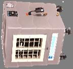
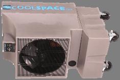
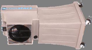
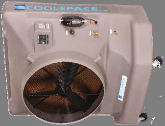
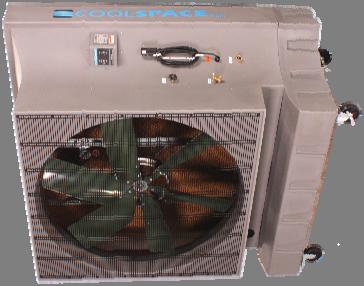
4 SIGNAL WORD DEFINITIONS DANGER DANGER indicates an imminently hazardous situation which, if not avoided, WILL result in death or serious injury. WARNING CAUTION CAUTION WARNING indicates a potentially hazardous situation which, if not avoided, COULD result in death or serious injury. CAUTION indicates a potentially hazardous situation which, if not avoided, MAY result in minor or moderate injury. CAUTION used without the safety alert symbol indicates a potentially hazardous situation which, if not avoided, MAY result in property damage. As defined in ANSI Z Introduction: COOL-SPACE is patented and a registered Trade Mark of Advanced Radiant Systems, Inc. and manufactured in Indiana. COOL-SPACE is a compact, self-contained, high-efficiency portable evaporative cooler capable of lowering existing temperatures by as much as 30 degrees. 2.0 Unpacking your COOL-SPACE unit: IMPORTANT Carefully examine the carton for damage before opening. If the carton is damaged, notify the shipping company immediately. The 16 and smaller units are shipped in a cardboard box. Open the top panel and lift the unit out. The larger units are shipped on a wooden skid stapled to a cardboard cover and lid. The cardboard cover simply lifts off the COOL-SPACE unit after removing the staples. The cooler must be lifted off the wooden skid. 3.0 Set-up of the COOL-SPACE unit: The COOL-SPACE unit is factory tested and ready to use. The unit should be placed on a level surface, and the casters locked to prevent inadvertent movement. Follow instructions below to connect water and electrical supply. 3.1 Connecting the water supply: The COOL-SPACE unit comes equipped with a female garden hose water source connection. Attach the unit to a standard garden hose outlet for a water source. It is not recommended that the unit be attached to any water source with operating pressures above 60 psi. A 60 psi pressure reducing valve is installed on your unit. If you have purchased the optional portable water tank, use a standard garden hose (not provided) to connect the tank to the cooler. 2

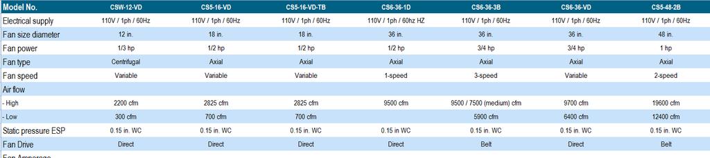
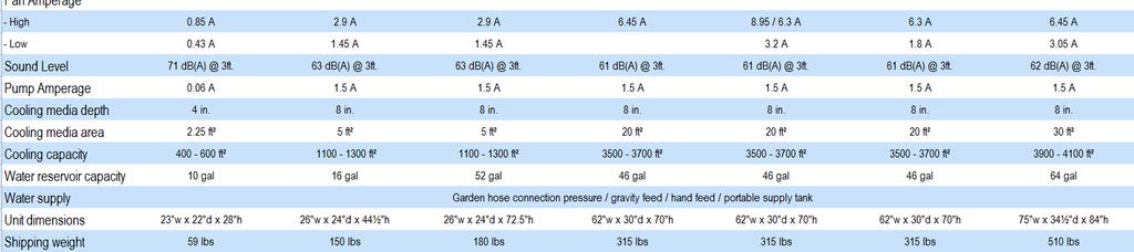
5 CAUTION Do not connect the COOL-SPACE unit to any water source where water pressure exceeds 60 psi. This will cause permanent damage to the unit. 3.2 Connecting the electrical supply: All models utilize standard 120-volt power supply. The unit should be plugged into a fused or circuit breaker protected 20 amp, 120 volt, 60 Hz circuit. If the unit is for overseas operation or is custom built for a specific application, please consult the factory for proper configuration. A ground fault circuit interrupter protected circuit is strongly recommended. IMPORTANT The COOL-SPACE unit should be plugged into a fused or circuit breaker protected 20 amp, 120 volt, and 60 Hz circuit. If the unit is for overseas operation or is custom built for specific application, please consult the factory for proper configuration. If an extension cord is required, refer to Table 2 for the proper 3-conducter heavy-duty cord required. Table 1 shows the amperage requirements for the specific models. WARNING Do not exceed the extension cord s amperage ratings. Undersized extension cords result in excessive voltage drops, which cause the electric motors to generate excessive heat. This condition results in inefficient motor operation and premature motor failure, WHICH WILL VOID THE WARRANTY. Table 1. Electrical requirements for US operation CS Model Number Volts ± 10% Frequency (Hz) Running Amps 16VD D B VD D Table 2. Cord size requirement based on length and max amp draw Length Cord Size Ft. 16 Ga 14 Ga 12 Ga 10 Ga A 15 A 15 A 15 A A 14 A 15 A 15 A A 12 A 13 A 15 A A-Amps at 125 volt (Derate for lower voltage) 3
6 4.0 Operating procedures: There are 3 factors to consider when determining where to place the COOL-SPACE unit. 1. Fresh air supply: The inlet side of the unit (pad side) requires a constant, uninterrupted supply of fresh air for maximum performance. A distance of 3 ft clear space is recommended. 2. Discharge air flow: The cool air discharged from the unit should be free of obstruction to allow the air to circulate in order to maximize the cooling zone. 3. Ventilation: In order to operate at maximum effectiveness, it is helpful to have provisions to remove the air discharged from the COOL-SPACE unit from the cooling area. This ensures that the COOL-SPACE unit does not recirculate air that has already been through the evaporative cooling process. The COOL-SPACE unit must be placed on a level surface to operate correctly. The units create an oval shaped air pattern that can reach out as far as 70 feet with large fans. Obstacles such as racks and workbenches may interfere with the cooling zone. An attempt should be made to locate the unit in such a manner that interruption of the air pattern is held to a minimum. Multiple units may be required to cover larger areas. When the COOL-SPACE unit is placed near a wall or other vertical obstruction, it is recommended that there be a space of at least 3 feet between the back (pad side) of the unit and the obstruction. This ensures that a clear supply of fresh air is able to get to the inlet of the unit. A platform or framework may be built to support the COOL-SPACE unit in order to place the unit out of the way of obstacles. When constructing a framework, ensure that it will not allow the COOL-SPACE unit to tip over. Also, the structure must be able to accommodate the unit plus the added weight of the water in both the pads and the reservoir. 16 Unit: 84 lbs. (unit) + 24 lbs. (pad operating weight) lbs. (15 gal. reservoir) = 228 lbs. 36 Unit: 295 lbs. (unit) + 60 lbs. (pad operating weight) lbs. (48 gal. reservoir) = 739 lbs. 48 Unit: 497 lbs. (unit) lbs. (pad operating weight) lbs. (64 gal. reservoir) = 1,109 lbs. 4.1 Filling the unit with water: Once the COOL-SPACE unit has been hooked up to a water source as described in 3.1, turn the water supply valve on and the unit will fill with water. The float valve will shut off the water flow when the sump is full. 4
7 4.2 Starting the fan: Turn the fan switch to HIGH speed on start-up, allow motor to reach maximum speed, then set at Medium or Low. IMPORTANT DO NOT flood the pads with water, keep them moist. New pads take a few days to become completely saturated. It is normal to have several dry streaks on the face of the pads about 1 or 2 inches wide. If the streaks are larger or unevenly spaced, adjust the flow control knob to allow more water to flow to the pads. NOTE: New pads may also emanate an odor under initial operating conditions from the resin used to construct the media. Flush the pads by running the pump without the fan running for approximately 2 hours. Empty the sump and refill. Repeat if odor still exists. 4.3 Starting the pump and adjusting the water flow: NOTE: Have fan running while adjusting the water flow. Once the sump is full, the pump switch may be turned to the ON position. The flow control knob will need to be adjusted on initial start-up. It is located at the right side of the unit, it controls the volume of water that is delivered to the top of the cooling pads. CAUTION Prolonged use of hard water without proper water treatment will create mineral deposit build up causing the pump to fail which is NOT COVERED BY WARRANTY 5.0 Maintenance and storage: DANGER ELECTRICAL SHOCK HAZARD Disconnect the power supply before performing any service or maintenance on the unit. Failure to do so may result in serious injury or death. The COOL-SPACE unit is constructed of durable industrial grade components and requires minimal maintenance. The housing is constructed of corrosion-free polyethylene. The fan is galvanized for corrosion resistance. The motor is TEAO moisture resistant specifically designed for wet applications. All other components are designed for wet duty applications to ensure long life of the unit. 5.1 Removing the cooling media to access the inside of the unit: In order to perform any maintenance on internal components, the cooling pads must be removed to access the inside of the unit. 5
8 1. Use a wrench to remove the (2) bolts connecting the pad retainer (pad side) to the housing. 2. Each pad can be tilted out of the unit and lifted out of the drain tray. Note: Reinstall pads correctly. 5.2 Daily maintenance: When shutting down the COOL-SPACE unit at the end of each workday, the pump should be turned off approximately 15 minutes before the fan is turned off. This will allow the pads to drain and dry out. This simple guideline will ensure long and efficient pad life as well as help to control mildew and bacteria growth. IMPORTANT Shut off pump 15 minutes before shutting off fan to allow pads to drain and dry out. This will help pad life and operation and control mildew growth. 5.3 Periodic maintenance: Depending on how often the COOL-SPACE unit operates, this procedure should be performed anywhere from every week for heavy use to monthly for light use. Shut down the unit and drain the water sump. The cooling pads act as a filtering agent and remove dust and other particles from the incoming air stream. These particles will flow into the sump and collect there. Also, impurities in the water will collect in the sump. 1. Close the water flow valve and open the drain valve. 2. Run pump until sump is dry then immediately shut off pump. 3. Turn unit off and disconnect power supply. WARNING ELECTRICAL SHOCK HAZARD Disconnect the power supply before performing any service or maintenance on the unit. Failure to do so may result in serious injury or death. 4. Remove cooling pads, refer to Clean out reservoir with either a towel or wet/dry vacuum. 6. Check belt for tightness, if applicable. 7. Remove the water spray bar, remove its plug. Using pump flush tube and insure holes are free of debris. 8. Reinstall pads and pad retainer. 9. Reinstall back guard (if applicable). To keep the COOL-SPACE unit operating at peak efficiency, ensure that the cooling pads are kept clean and dust-free. Dust and other particles have an adverse effect on the media s ability to introduce water into the air stream. If the pad surface becomes dirty or dusty, clean with a soft brush and water. The fan motor may require periodic lubrication depending on the COOL-SPACE model. Check your model for an oil fill location on the motor. A few drops of light oil each year will extend motor life. 6
9 5.4 Storage: 1. Remove the pads, as described in 5.1.1, clean with a soft brush and water to remove dust and debris. 2. Drain sump using above procedure and wipe dry. 3. Store the COOL-SPACE unit in a dry area and cover if possible to prevent dust build-up. 6.0 Troubleshooting/Repair: 6.1 Troubleshooting: WARNING ELECTRICAL SHOCK HAZARD Disconnect the power supply before performing any service or maintenance on the unit. Failure to do so may result in serious injury or death. The COOL-SPACE unit consists of three systems, it is important to determine which system of the COOL-SPACE unit the problem is associated with. This may not always be obvious, in that certain problems may be associated with more than one system. When determining which system has a problem, you must define associated problem, (i.e. the pump is not running). Although this might seem a bit simplified, several things may cause this particular problem. So while defining the problem, a careful check of all systems should be made to fully understand the extent of the problem. If you have a complete understanding of all of the systems of the COOL-SPACE unit and how they depend on each other, it will be simple to define and solve any problem. Although the COOL-SPACE unit is designed to be simple to maintain, it will be necessary to have some basic hand tools (screwdrivers, pliers, adjustable wrenches, etc.) as well a volt/ohm meter when troubleshooting the electrical system. Fan System CAUTION Please use caution when troubleshooting or repairing all electrical components. Be certain that all power is disconnected from the COOL-SPACE unit before the cooling pads or fan guard are removed to gain access to the fan 7
10 Direct & Belt Drive Models Problem Check Solution Fan won't run and makes Power cord, extension cord, Reconnect power or no sound. switches, circuit breaker. extension cord. Fan motor won t run and makes a humming sound. Breaker trips or fuse blows when fan is started. Motor overheating and shutting off. Restarting several minutes later. Fan motor won t run and switch makes soft clicking sound. Fan blade doesn t turn and unit makes squealing sound. Fan belts do not last very long. Fan will not reach speed but turns and makes humming sound. Blade in contact with shroud. Motor stalled (will not turn by hand). Motor stall. Check power source for min. 115v/20 amp. Extension cord. Extension cord gauge too small. Inlet air obstructed or too close to wall. Faulty motor. Switch making good contact. Start capacitor leaking from cover. Motor stall (as above). Fan belt, loose or broken. Fan pulley spinning on shaft. Motor and fan pulleys alignment. Capacitor (where visible) and motor electrical connections. Extension cord to small. Reset breaker. Re-center blade hub. Replace motor. Replace motor. Upgrade power supply. Replace with heavier cord. Replace with heavier cord. Provide minimum 3 inlet clearance. Replace motor. Replace switch. Replace capacitor. Replace motor. Tighten or replace fan belt. Tighten pulley set screw. Realign motor and mount. Replace capacitor or motor. Increase cord gauge. 8
11 Water System The water delivery system consists of three primary elements: 1) Water Distribution System, 2) Spray Bar Assembly, 3) Pump, Troubleshooting of this system is fairly simple. The water Distribution System consists of two assemblies: A) The Water Inlet Assembly, B) The Hose & Valve Assembly. The Water Inlet Assembly is made up of three components: 1) The brass bulkhead fitting, 2) The float valve connection hose, 3) The float valve assembly. The Hose & Valve assembly consists of three elements: 1) Spray Bar Assembly, 2) Valve Assembly, 3) Connection hose. Floor at side of COOL- SPACE unit is wet Water System Problem Check Solution Water inlet hose is loose at supply hose or inlet hose is loose at bulkhead fitting. COOL-SPACE unit overflows from reservoir or is spitting water through fan. Water spitting from the unit. Water leaking from drain valve. Water leaking from water flow control valve. Too many dry streaks in the pads. Water spitting from the unit. Float valve hose is loose at bulkhead fitting or at float valve. Water pressure is too high to allow float valve to shutoff (60psi max). Float valve is not seating properly. Cracked Hose & Valve Assembly. For worn washer, worn stem. Make sure drain valve is closed. Washer worn. Stem worn. Jam nut loose. Holes in spray bar blocked. Adjust water flow. Hose connection loose. Faulty hose. Flooding of pads. Tighten connections and/or replace hose washers. Tighten connections and/or replace hose washers. Reduce water pressure by adding an inline reducer. Check float valve. Replace float orifice. Replace Hose & Valve Assembly. Replace washer. Replace drain valve. Replace water flow control valve. Tighten Jam nut. Remove spray bar. Remove plug and clean tube and holes. Open water flow control valve. Tighten hose. Replace hose and washer. Adjust water flow control valve. 9
12 Pump motor will not run when switch is turned on. Pump Problem Check Solution Turn fan on to check for power. Is water level high enough to make the lowwater cut-off circuit. Pump motor hums when switch is turned on, but does not pump water. Pump makes loud noise while running. Breaker trips or fuse blows when switch is turned on. Pump won t run and power is available. Pump is functional. Pump runs but does not pump water. 6.2 Repair procedures: Obstruction in impellar. Pump motor failure. Object(s) in impellar, impellar loose. Pump bearings bad. Check power cord length and breaker rating. Check for locked-up pump. Make certain switch is working. Is water level high enough to make the lowwater cut-off circuit. Air lock in outlet side of pump. Make certain impellar is turning in pump. CAUTION Repairs should be performed by a qualified technician! If fan doesn t start; check breaker and cord plug-in. If fan does start; check for power to and through pump switch (when turned on). Fill water reservoir. Remove object(s). Replace pump. Remove object(s). Replace pump. Refer to pg. 5 for unit amperage draw and pg. 6 to determine required cord gauge. Replace pump. Replace switch if not completing circuit. Fill water reservoir. Turn off and on to bleed. If not, replace pump. Warning: Care must be taken to avoid electrical shock when servicing. DISCONNECT POWER WHEN SERVICING. Fan Motor Replacement Belt Drive Models (see section 5.1 for pad removal) 1. Remove the motor wiring plate and disconnect motor wires. Mark each wire with a marker that will allow easy matching when new motor is installed. 2. Loosen the four bolts that fasten the motor to the bracket. This will allow the removal of the motor. 3. Remove the motor pulley by loosening the set screw and slide the pulley off. 4. Install the pulley onto the new motor and slightly tighten the set screw. 5. Place new motor onto the mounting bracket and reinstall the four mounting bolts and tighten. 10
13 6. Visually align the motor pulley and fan pulley by using the belt as a reference. Adjust the motor pulley in or out to align. Tighten the motor pulley. 7. Loosen the four bolts that secure the mounting bracket to the upright. 8. Lower the bracket slightly until the belt is tight (but not tight enough to overload the motor) and then tighten the four bracket bolts. 9. Replace the motor wires as marked from step # 5. Replace wire ties to prevent cord from getting in fan blade. 10. Replace motor wiring cover plate and inspect to be certain that the rubber seal is properly seated. 11. Replace cooling pads and guards and reconnect power and test motor. Face Mounted Direct Drive Models 1.) Remove the motor wiring plate and disconnect motor wires. Mark each wire with a marker that will easily allow matching when new motor is installed. 2.) Remove fan guard and fan blade. 3.) Loosen the four nuts that secure the motor to the motor braces. This will allow the removal of the motor. 4.) Place new motor in position and reinstall the four mounting nuts and tighten. 5.) Reattach the fan blade onto the motor shaft and tighten the set screws being sure that the motor shaft extends the same distance beyond the blade hub. 6.) Check that the motor and fan assembly turns freely, and fan blade does not strike the motor supports. 7.) Replace the motor wires as marked from step #1. Replace wire ties to prevent cord from getting in the fan blade. 8.) Replace motor wiring cover plate and inspect to be certain that the rubber seal is properly seated. 9.) Replace cooling pads and guards and reconnect power and test motor. 36 Variable Speed Direct Drive Models 1.) Remove cap off rear of motor. Disconnect wires. Clip wire ties. 2.) From the front, remove 4 fan mounting bolts. (Support fan to ensure it doesn t fall.) 3.) With fan out of unit remove cap on blade to access blade mounting nut. Remove nut and blade. 4.) Remove mounting arms by loosening 8 nuts and slide arms out of slot. (Make note of arms position for reinstallation.) 5.) Install arms and blade or new motor. 6.) Install fan in opening and install mounting bolts. 7.) Reconnect wires and tie cord to motor arm to keep them out of fan. Pump Replacement 1.) Disconnect hose from pump. 2.) Remove pump bracket. 3.) Disconnect wiring from pump switch. (Note: Units built after unplug from top of pump by removing 2 screws.) 11
14 4.) Remove pump from water sump and install new pump. Reverse the above procedures to reconnect the wiring, lift pump bracket and reconnect the hose. Secure wires to fan frame with wire ties to clear the fan blades. 5.) Reinstall cooling pads and guards, reconnect power and test pump. 6.3 Technical support: Technical support and service is available directly from your distributor or COOL- SPACE Technical Support Hot Line at Warranty: Under normal use, the Warranty covers (12) twelve months on the pump and (24) twentyfour months from date of invoice for the remaining components. Refer to the manufacturer s Warranty Policy for details. 7.1 Warranty Form: Fill out and return to manufacturer. Supplied with unit. 7.2 Warranty parts: Warranty replacement parts are available through your local Distributor or Supplier where you purchased your COOL-SPACE unit. If you have any questions or concerns, please contact us direct at or at sales@cool-space.com. Please have your model number and serial number ready. DO NOT DISCARD FAULTY PARTS! THEY WILL NEED TO BE RETURNED FOR WARRANTY CREDIT. 7.3 Optional accessories: Accessories are available from your local Distributor or Supplier or can be found online at 12
15 Fan Motor CS-F16 (Motor/Shroud/Fan Combo) CS-M162 CS-M162-1 (CS2 Series) CS-M361 (Face Mount) CS-M361-AC (Base Mount) CS-M363B CS-M36V CS-M482B 7.4 Common Replacement Parts 16 Variable Speed 16 Two Speed 16 Two Speed 36 Single Speed 36 Single Speed 36 Three Speed 36 Variable Speed 48 Two Speed Switches CS-E110 CS-E111 CS-E115 CS-E185 On/Off Pump & Single Speed Fan Two Speed Three Speed Variable Speed Pump CS-E , 36 & 48 8 Pads CS-H610 CS-H613 CS-H (2 Required) 36 (5 Required) 48 (6 Required) Float Assembly CS-P052 (Before 08/09) 16, 36 & 48 CS-P053.1 (After 08/09) 16, 36 & 48 CS-A131 (After 01/11) 16, 36 & 48 13
16 8.1: CS5-16-2D / CS5-48-2D - WIRING SUB-ASSEMBLY FAN SWITCH RED WHITE RED GREEN PUMP SWITCH PUMP GREEN RED WHITE FAN MOTOR Two Speed Assy. No. CS-A580 Revised
17 8.2: CS5-36-1D / CS6-36-1D - WIRING SUB-ASSEMBLY FAN SWITCH RED PUMP SWITCH PUMP FAN MOTOR Single Speed Assy. No. CS-A580 Revised
18 8.3: CS5-36-3B / CS6-36-3B - WIRING SUB-ASSEMBLY 4 POSITION SWITCH TO SWITCH TERMINAL NO. FAN SWITCH #1 #2 #4 ORG #8 RED #7 RED BRN PUMP SWITCH PUMP RED ORG FAN MOTOR Three Speed Assy. No. CS-A580 Revised
19 8.4: CS5-16-VD / CS5-36-VD / CS6-36-VD - WIRING SUB-ASSEMBLY FAN SWITCH RED RED RED PUMP SWITCH PUMP FAN MOTOR Variable Speed Assy. No. CS-A580 Revised
20 9.0 How evaporative cooling works: In order to have an understanding of how the COOL-SPACE portable evaporative cooler works a basic understanding of psychrometrics is necessary. Psychrometrics is the branch of thermodynamics devoted to the study of air and water vapor mixtures. The psychrometric chart is a graphical representation of properties of moist air. To illustrate how the COOL-SPACE unit operates, some of the relevant properties are described in this section followed by a sample application. Dry-bulb temperature is measured with an ordinary thermometer. Dry-bulb temperature lines on the psychrometric chart are the vertical lines shown in Figure 1. Figure 1. Wet-bulb temperature is measured using a wet-bulb thermometer, which is an ordinary liquid-in glass thermometer whose bulb is enclosed by a wick moistened with water, often called a sling psychrometer. The psychrometer is whirled around in the air. If the air is not saturated (100% relative humidity), the water in the wick evaporates and the water temperature falls below the dry-bulb temperature. Figure 2 shows the wet-bulb temperature lines on the psychometric chart. Figure 2. 18
21 Dew-point temperature is the temperature to which a given sample of air must be cooled so that moisture will start condensing out of it. When air is saturated, the dry-bulb, wetbulb and dew-point temperatures will all be equal. The horizontal lines in Figure 3 show the dew-point temperature on the psychrometric chart. Figure 3. Relative humidity is the amount of moisture in the air relative to the amount of moisture the air would hold if saturated at that dry-bulb temperature. Percent humidity is not the same as relative humidty and is not used in HVAC design. Figure 4 shows the relative humidy curves on the psychrometric chart. Figure 4. 19
22 The following example illustrates the use of the psychrometric chart as it relates to evaporative cooling. Since all of the items described above are properties, any two of them describe a state point on the psychrometric chart. Once this point is determined, the values of all the other properties can be read from the chart. Figure 5 below shows a Mollier type psychrometric chart for atmospheric pressure. The dot shown in Figure 5 is a state point. The following properties are known about the air/water mixture at this state. dry-bulb temperature: 97 F dew-point temperature: 71 F wet-bulb temperature: 78 F relative humidity: 43% The COOL-SPACE unit is a highefficiency portable evaporative cooler. The unit draws air across water saturated high-efficency cooling pads which forces the air to evaporate the water, thus removing energy from the air. Take the air/water mixture described by the state point above, with a dry-bulb temperature of 97 F and 43% relative humidity, for example. As the air passes through the cooling media on the COOL-SPACE unit, moisture is added to the air increasing the relative humidity. This increase in relative humidity brings a decrease in dry bulb temperature. When the relative humidity is raised to 70%, the dry bulb temperature has dropped to 86 F. When the humidity level approaches 100%, the dry bulb temperature has dropped nearly 20 F to 78 F. 20
23
24 A Division of Advanced Radiant Systems, Inc. Phone: Fax: CS5/6Man /20
Operation & Maintenance Manual for
 Operation & Maintenance Manual for CS5-16, CS5-36 & CS5-48 Series 12910 Ford Drive Fishers, IN 46038 Phone: 317-577-0417 Fax: 317-842-3989 1-800-557-5716 www.cool-space.com sales@cool-space.com Operation
Operation and Maintenance Manual GLACIER TALL BASE CS5-16-VD-TB CS5-18-VD-TB2 120V/60HZ
 Operation and Maintenance Manual GLACIER TALL BASE CS5-16-VD-TB CS5-18-VD-TB2 120V/60HZ Operation & Maintenance Manual Table of Contents: 1.0 Introduction 1 2.0 Unpacking your COOL- SPACE 1 3.0 Set-up
Operation and Maintenance Manual 120V/60HZ
 Operation and Maintenance Manual 120V/60HZ GLACIER CS5-16-VD CS5-16-VD-TB CS5-18-VD CS5-18-VD-TB AVALANCHE CS6-36-1D CS6-36-VD BLIZZARD CS6-50-VD Operation & Maintenance Manual 60HZ Models Table of Contents:
Operation and Maintenance Manual BLIZZARD50 CS6-50-VD 120V/60HZ
 Operation and Maintenance Manual BLIZZARD50 CS6-50-VD 120V/60HZ CS6-50-VD Operation & Maintenance Manual Table of Contents: 1.0 Introduction 1 2.0 Unpacking your COOL- SPACE 1 3.0 Set-up of COOL-SPACE
Operation and Maintenance Manual 120V/60HZ
 Operation and Maintenance Manual 120V/60HZ GLACIER CS5-18-VD CS5-18-VD-TB AVALANCHE CS6-36-1D CS6-36-VD BLIZZARD CS6-50-VD Contents 1.0 INTRODUCTION... 1 2.0 UNPACKING YOUR COOL-SPACE UNIT... 1 3.0 SET-UP
CSW-12-VD Portable Evaporative Cooler
 A Product of Advanced Radiant Systems, Inc. www.cool-space.com sales@cool-space.com CSW-12-VD Portable Evaporative Cooler IMPORTANT SAFETY INFORMATION INSIDE MADE IN Serious injury or death possible Read,
48 MaxxAir Portable Evaporative Cooler Owner s Manual
 48 MaxxAir Portable Evaporative Cooler Owner s Manual This Manual covers all of the following MaxxAir Portable Evaporative Coolers. EC48D1 MaxxAir 48 Belt Drive 2 Speed File this owner s manual in a safe
OWNERS MANUAL U.S. Patent 6,223,548 U.S. Patent D 362,905 U.S. Patent 6,502,414
 OWNERS MANUAL U.S. Patent 6,223,548 U.S. Patent D 362,905 U.S. Patent 6,502,414 Port-A-Cool Products and Accessories and Küül Pads Cooling Media are manufactured by manufactured by port-a-cool, llc Port-A-Cool,
6,223,548 FOR ELECTRIC MODELS PAC2K36EP PAC2K48EP
 PORT-A-COOL Series 2000 OWNERS MANUAL for Hazardous Location Units U.S. Patent 6,223,548 FOR ELECTRIC MODELS PAC2K36EP PAC2K48EP PORT-A-COOL Evaporative Cooling Units OWNERS MANUAL FOR HAZARDOUS LOCATION
18 MaxxAir Portable Evaporative Cooler Owner s Manual This Manual covers the EC18DVS MaxxAir Portable Evaporative Cooler.
 18 MaxxAir Portable Evaporative Cooler Owner s Manual This Manual covers the EC18DVS MaxxAir Portable Evaporative Cooler. File this owner s manual in a safe place for future reference. It contains operating
Manual update 2016 MC37/MFC3600
 Manual update 2016 MC37/MFC3600 SETUP INSTRUCTIONS Evaporative cooling works on the principle of heat absorption by moisture evaporation. Simply put, heat is removed from the air as water evaporates. You
Manual for MC37/MFC3600
 Manual for MC37/MFC3600 SETUP INSTRUCTIONS Evaporative cooling works on the principle of heat absorption by moisture evaporation. Simply put, heat is removed from the air as water evaporates. You feel
Port-A-Cool unit. Pneumatic Owner s Manual. series manufactured by port-a-cool, llc FOR PNEUMATIC MODELS PAC2K36AD, PAC2K24AD, PAC2K16AD
 Port-A-Cool unit series 2000 Pneumatic Owner s Manual FOR PNEUMATIC MODELS PAC2K36AD, PAC2K24AD, PAC2K16AD manufactured by port-a-cool, llc PORT-A-COOL unit OWNERS MANUAL PNEUMATIC MODELS PAC2K36AD, PAC2K24AD,
Manual for MC91 SETUP INSTRUCTIONS
 Manual for MC91 SETUP INSTRUCTIONS Evaporative cooling works on the principle of heat absorption by moisture evaporation. Simply put, heat is removed from the air as water evaporates. You feel this principle
TURBO Fiberglass Cone Fan and Grill Fan 48'' Belt Drive. Installation & Operator s Instruction Manual
 TURBO Fiberglass Cone Fan and Grill Fan 48'' Belt Drive Installation & Operator s Instruction Manual July 1998 MV1383B Chore-Time TURBO TM Fan Extended Warranty Chore-Time Equipment warrants new TURBO
Nilfisk Inc Winnetka Avenue North Minneapolis, MN REV.03( ) VF80189
 VF80189") Nilfisk Inc. 9435 Winnetka Avenue North Minneapolis, MN 55445 www.usviper.com REV.03(05-) VF8089 SAFETY PRECAUTIONS This machine is intended for commercial use. It is constructed for use in an indoor
Nilfisk Inc. 9435 Winnetka Avenue North Minneapolis, MN 55445 www.usviper.com REV.03(05-) VF8089 SAFETY PRECAUTIONS This machine is intended for commercial use. It is constructed for use in an indoor
Manual for MC21A SETUP INSTRUCTIONS
 Manual for MC21A SETUP INSTRUCTIONS Evaporative cooling works on the principle of heat absorption by moisture evaporation. Simply put, heat is removed from the air as water evaporates. You feel this principle
Water Boilers ME10EN, ME15EN. Table of Contents
 Water Boilers ME10EN, ME15EN Operator Manual Model ME15EN Model ME10EN Safety Information...2 Rough-In Drawing...3 Installation...4 Priming...5 Cleaning...5 Table of Contents Adjustments...6 Maintenance...7
User s Manual and Operating Instructions
 User s Manual and Operating Instructions Model Numbers: CL-30P-DDF, CL-20F-DDF, CL-24O-DDF, CL-30-DDF READ AND SAVE THESE INSTRUCTIONS IMPORTANT: Read and understand all of the directions in this manual
OPERATOR S MODEL HCN-5 HHC-136 HEATED HOLDING CABINET REGISTER WARRANTY ONLINE AT
 OPERATOR S M A N U A L HEATED HOLDING CABINET MODEL HCN-5 HHC-136 REGISTER WARRANTY ONLINE AT WWW.HENNYPENNY.COM TABLE OF CONTENTS Section Page Section 1. INTRODUCTION... 1-1 1-1. Heated Holding Cabinet...
EBAC MODEL WM150 INDUSTRIAL DEHUMIDIFIER OWNER S MANUAL
 EBAC MODEL WM150 INDUSTRIAL DEHUMIDIFIER OWNER S MANUAL WM150 OWNERS MANUAL Page 1 of 9 INTRODUCTION Designed for a wide range of applications, the WM150 is a rugged, industrial unit, which utilizes an
Operation Manual SCT14B and SCT18B. Inspection. 3 General Description. 3 General Requirements. 3 Standard Features.
 Spot Cooling Systems, Inc. 120 Century Drive Suite 00 Carrollton, TX 7006 00-6-776 Operation Manual SCT1B and SCT1B Warning! Improper installation, adjustment, alteration, service, or maintenance can cause
TCUT10UL 2.5 HP 10 Tile Saw Assembly & Operating Instructions
 TCUT10UL 2.5 HP 10 Tile Saw Assembly & Operating Instructions READ ALL INSTRUCTIONS AND WARNINGS BEFORE USING THIS PRODUCT. This manual provides important information on proper operation and maintenance.
User Manual Box Exhaust Fan Series (Belt Drive)
") User Manual Box Exhaust Fan Series (Belt Drive) 36" Box Exhaust Fan with Three Wing Blade Box with Aluminum Shutter 54" Box with Cone 800-779-3267 sales@schaeferfan.com www.schaeferfan.com 2013 Schaefer
User Manual Box Exhaust Fan Series (Belt Drive) 36" Box Exhaust Fan with Three Wing Blade Box with Aluminum Shutter 54" Box with Cone 800-779-3267 sales@schaeferfan.com www.schaeferfan.com 2013 Schaefer
User s Manual and Operating Instructions
 User s Manual and Operating Instructions Model Numbers: PT-18W-DDF-A, PT-20F-DDF-A, PT-20S-DDF, PT-24O-DDF, PT-24-DDF, PT-24-DDF-F, PT-30-DDF, PT-30P-DDF-A, PT-30P-DDF-AF READ AND SAVE THESE INSTRUCTIONS
UNDERCOUNTER LABORATORY REFRIGERATORS and FREEZERS Installation, Operation and Maintenance Instructions
 UNDERCOUNTER LABORATORY REFRIGERATORS and FREEZERS Installation, Operation and Maintenance Instructions INSPECTION When the equipment is received, all items should be carefully checked against the bill
TIDALWAVE I/G POOL PUMP INSTRUCTION MANUAL
 TIDALWAVE I/G POOL PUMP INSTRUCTION MANUAL READ THIS MANUAL CAREFULLY BEFORE USING YOUR PUMP 88 PUMP PARTS BREAKDOWN REF # Order # Mfr # Description 1 NEP4 AC 348 Lid Knobs NEP AC 380 Strainer Lid 3 NEP6
Portable Evaporative Cooling System
 Portable Evaporative Cooling System User s Manual Manufactured by HH Technologies, Inc. 1733 County Road 68 Bremen, Alabama 35033 256-287-7000 Part No 4801-5035 Rev 03-2017 User s Manual PolarCool Table
INLET DAMPER WALL FAN UNIT
 FARM PRODUCTS DIVISION MEMBER OF AMCA AMERICAN COOLAIR CORPORATION P.O. BOX 2300 JACKSONVILLE, FLORIDA 32203 PHONE (904) 389-3646 FAX (904) 387-3449 E-MAIL - agfans@coolair.com INLET DAMPER WALL FAN UNIT
Portable Evaporative Cooling System
 Portable Evaporative Cooling System User s Manual Manufactured by HH Technologies, Inc. 1733 County Road 68 Bremen, Alabama 35033 256-287-7000 Part No 4801-5035 Rev 03-2017 User s Manual PolarCool Table
BURWELL BIDET TOILET SEAT INSTALLATION
 BEFORE YOU BEGIN We recommend consulting a professional if you are unfamiliar with installing plumbing fixtures. Signature Hardware accepts no liability for any damage to the product, plumbing, toilet,
HEDMAN DI-50. Endorser Instructions. Hedman DI-50 Operators Guide
 HEDMAN DI-50 Endorser Instructions Hedman DI-50 Operators Guide 25-0132-20 TABLE OF CONTENTS 1. INTRODUCTION...1 1.1 DI-50 Description...1 1.2 Items Included...1 1.3 Safety Terms...2 1.4 Safety Precautions...3
OWNERS INSTRUCTION MANUAL
 P O R T A B L E N A T U R A L A I R C O N D I T I O N E R S OWNERS INSTRUCTION MANUAL MEGACOOL MASTERCOOL MILLENIA C O O L A I R A N Y W H E R E! by 1 PORTABLE EVAPORATIVE AIR COOLER - IMPORTANT SAFETY
36 & 48 E-Z Cone Fan. Installation & Operator s Instruction Manual (Direct Drive)
") 36 & 48 E-Z Cone Fan Installation & Operator s Instruction Manual (Direct Drive) September 1997 MV1433C Chore-Time Warranty Chore-Time Equipment warrants each new product manufactured by it to be free
36 & 48 E-Z Cone Fan Installation & Operator s Instruction Manual (Direct Drive) September 1997 MV1433C Chore-Time Warranty Chore-Time Equipment warrants each new product manufactured by it to be free
Panel Fan Series Operators Manual (Galvanized and Polymer)
") Panel Fan Series Operators Manual (Galvanized and Polymer) Galvanized Panel Fan with Three Wing Blade IMPORTANT: READ AND SAVE THESE INSTRUCTIONS Read all instructions carefully before attempting to assemble,
Panel Fan Series Operators Manual (Galvanized and Polymer) Galvanized Panel Fan with Three Wing Blade IMPORTANT: READ AND SAVE THESE INSTRUCTIONS Read all instructions carefully before attempting to assemble,
RCM-77. Instruction Manual. G-Series Cooler. U.S. Patent No. 8,215,125 RECHARGE COLD MERCHANDISER
 G-Series Cooler RECHARGE COLD MERCHANDISER U.S. Patent No. 8,215,125 Instruction Manual FOR YOUR FUTURE REFERENCE This easy-to-use manual will guide you in getting the best use of your cooler. Remember
Panel Fan Series Operators Manual (Galvanized and Polymer)
") Panel Fan Series Operators Manual (Galvanized and Polymer) 52" Belt Drive, Galvanized Panel Fan with Three Wing Blade IMPORTANT: READ AND SAVE THESE INSTRUCTIONS Read all instructions carefully before
Panel Fan Series Operators Manual (Galvanized and Polymer) 52" Belt Drive, Galvanized Panel Fan with Three Wing Blade IMPORTANT: READ AND SAVE THESE INSTRUCTIONS Read all instructions carefully before
OPERATING & SERVICE PARTS MANUAL HDS-215 COMBINATION SHRINK SYSTEM
 OPERATING & SERVICE PARTS MANUAL HDS-215 COMBINATION SHRINK SYSTEM FOR HOT KNIFE AND IMPULSE MACHINES READ ALL INSTRUCTIONS CAREFULLY BEFORE OPERATING EQUIPMENT TABLE OF CONTENTS Electrical Requirements
(The chances are you re never going to read me) Owner s Manual. Model S10E.
 Owner s Manual. Model S10E.") (The chances are you re never going to read me) Owner s Manual Model S10E www.simplicityvac.com 1 Contents Getting Started Important Safety Instructions 2 Polarization Instructions 3 State of California
(The chances are you re never going to read me) Owner s Manual Model S10E www.simplicityvac.com 1 Contents Getting Started Important Safety Instructions 2 Polarization Instructions 3 State of California
Integra Family. Operations Manual. Models: Integra TX SS, Integra HD, Integra DS, Integra DS LA, Integra UHS, Machine Name: Serial Number:
 Integra Family GREEN CIRCLE CERCLE VERT Operations Manual Models: Integra TX SS, Integra HD, Integra DS, Integra DS LA, Integra UHS, Machine Name: Date of Purchase: Serial Number: Service Center Number:
DOUBLE DOOR COMPACT REFRIGERATOR. User Manual MODEL:KSTRC312BW KSTRC312BB
 DOUBLE DOOR COMPACT REFRIGERATOR User Manual MODEL:KSTRC312BW KSTRC312BB SERIAL/MODEL # S - IMPORTANT SAFETY INSTRUCTIONS Read and Save These Instructions This Owner s Guide provides specific operating
 Installation Guide BI-98 Ice Maker www.u-lineservice.com Phone (414) 354-0300 FAX (414) 354-7905 Service & Parts Tech Lines Phone (800) 779-2547 FAX (414) 354-5696 OnlineService@U-Line.com 2005 U-Line
SELF-CONTAINED POWER MISTER
 00 North Main St. Fostoria, OH 0 Phone: 00-95-55 Fax: 9-5-0 www.tpicorp.com If you have questions about the product you have purchased or would like to leave us feedback please contact us via our website
Gen II Entree Bath. Maintenance Manual. All Models. Important Safety Instructions Read & Follow All Instructions Thoroughly
 Gen II Entree Bath All Models Maintenance Manual Important Safety Instructions Read & Follow All Instructions Thoroughly Note: The serial tag is at the first page of this manual package. The Standards
Instruction Book for HD Punch Machines
 Instruction Book for HD Punch Machines HD7700, HD7000 & HD7500H Setup & Operator Manual Issue 5 February 2012 Performance Design LLC. These electric punches have been designed to punch most any job that
DISHWASHER. Models DW2432 and DW2432SS. Installation Manual. Write Serial Number (on inner door of unit) here:
 here:") DISHWASHER Models DW2432 and DW2432SS Installation Manual Write Serial Number (on inner door of unit) here: Felix Storch, Inc. Summit Appliance Division 770 Garrison Avenue Bronx, New York 10474 www.summitappliance.com
DISHWASHER Models DW2432 and DW2432SS Installation Manual Write Serial Number (on inner door of unit) here: Felix Storch, Inc. Summit Appliance Division 770 Garrison Avenue Bronx, New York 10474 www.summitappliance.com
OPERATOR'S MANUAL. IMPORTANT: READ OPERATOR'S MANUAL CAREFULLY Please fill out & return your warranty card! DP80405
 CARBON SPOT 30 EXTRACTOR OPERATOR'S MANUAL IMPORTANT: READ OPERATOR'S MANUAL CAREFULLY Please fill out & return your warranty card! DP80405 Diamond Products www.diamondproductsus.com Printed in the U.S.A.
72 ONYX XL FLAT PANEL ELECTRIC FIREPLACE
 72 ONYX XL FLAT PANEL ELECTRIC FIREPLACE Model Numbers: 80005 OWNER S MANUAL WARNING Read and understand this entire owner s manual, including all safety information, before plugging in or using this product.
SAFETY PRECAUTIONS. 2) Before operating machine: - Make sure all safety devices are in place and operate properly.
 Before operating machine: - Make sure all safety devices are in place and operate properly.") TABLE OF CONTENTS Machine Components Safety Precautions Machine Set Up Machine Operation Machine Maintenance & Storage Troubleshooting Technical Specifications Parts Lists Wiring Diagram 1 2 3 3-4 5 6
TABLE OF CONTENTS Machine Components Safety Precautions Machine Set Up Machine Operation Machine Maintenance & Storage Troubleshooting Technical Specifications Parts Lists Wiring Diagram 1 2 3 3-4 5 6
Get Cleaning... What s your Vax s model number? User Guide. Carpet Washer Vax Careline: AU: NZ:
 User Guide Vax Careline: AU: 1300 361 505 NZ: 0800 800 900 Carpet Washer Get Cleaning... What s your Vax s model number? W8 W8 W0 W0 W0 W W W W W What s your serial number? (Located on the base of the
PORTACOOL CYCLONE OWNER S MANUAL PAC2KCYC01, PACCYC02, PACCYC03, PACCYC04, PACCYC06
 PORTACOOL CYCLONE OWNER S MANUAL PAC2KCYC01, PACCYC02, PACCYC03, PACCYC04, PACCYC06 QUICK SETUP 1 2 3 4 Remove box and pallet Position on level surface Use with GFCI device Fill tank or attach water hose
MNEFDD54 & MNBCDD54 GALVANIZED WALL FANS Installation, Operation, and Maintenance Instructions
 FARM PRODUCTS DIVISION MEMBER OF AMCA AMERICAN COOLAIR CORPORATION P.O. BOX 2300 JACKSONVILLE, FLORIDA 32203 PHONE (904) 389-3646 FAX (904) 387-3449 E-MAIL - fans@coolair.com MNEFDD54 & MNBCDD54 GALVANIZED
FD 90 / FD 95 Rotary Perforators
 FD 90 / FD 95 Rotary Perforators 11/2018 OPERATOR MANUAL SECOND EDITION TABLE OF CONTENTS SPECIFICATIONS 1 SAFETY PRECAUTIONS 1 DESCRIPTION 2 INSTALLATION AND OPERATION 3 INFEED TABLE ADJUSTMENT 3 OUTFEED
PANEL FAN SERIES OPERATORS MANUAL (Galvanized and Polymer)
") PANEL FAN SERIES OPERATORS MANUAL (Galvanized and Polymer) Galvanized Panel Fan IMPORTANT: READ AND SAVE THESE INSTRUCTIONS Read all instructions carefully before attempting to assemble, install, operate
PANEL FAN SERIES OPERATORS MANUAL (Galvanized and Polymer) Galvanized Panel Fan IMPORTANT: READ AND SAVE THESE INSTRUCTIONS Read all instructions carefully before attempting to assemble, install, operate
Wall Mount Electric Fireplace
 Wall Mount Electric Fireplace User Guide Thank you for purchasing the Ivation Wall Mount Electric Fireplace. This User Guide is intended to provide you with guidelines to ensure that operation of this
WAILEA OWNER S MANUAL
 WAILEA OWNER S MANUAL The blades in each pack are matched for equal weight to assure smooth fan operation. If more than one fan is being installed, be careful not to mix blades from different cartons.
HT650 TM FAN DRIVE SERVICE INSTRUCTIONS
 HT650 TM FAN DRIVE SERVICE INSTRUCTIONS When unpacking your product, remove all components and inspect them to ensure that no damage occurred during shipping. If any components are missing or damaged,
PWASH Gallon Parts Washer Assembly & Operating Instructions
 PWASH20 20 Gallon Parts Washer Assembly & Operating Instructions READ ALL INSTRUCTIONS AND WARNINGS BEFORE USING THIS PRODUCT. SAVE THESE INSTRUCTIONS FOR FUTURE REFERENCE. This manual provides important
INSTALLATION GUIDE Dual Fuel Ranges
 INSTALLATION GUIDE Dual Fuel Ranges Contents Wolf Dual Fuel Ranges......................... 3 Safety Instructions............................ 4 Dual Fuel Range Specifications.................. 5 Dual Fuel
MODEL MC-UL592 MC-UL594 POWER SOURCE. 230V - 240V ~ 50 Hz MAX INPUT 1400 W 1500 W NOMINAL INPUT DIMENSIONS (W x L x H)
") Order Number: PMMA091040CE Vacuum Cleaner MC-UL592/MC-UL594 SPECIFICATION MODEL MC-UL592 MC-UL594 POWER SOURCE 230V - 240V ~ 50 Hz MAX INPUT 1400 W 1500 W NOMINAL INPUT DIMENSIONS (W x L x H) 1200-1300
Order Number: PMMA091040CE Vacuum Cleaner MC-UL592/MC-UL594 SPECIFICATION MODEL MC-UL592 MC-UL594 POWER SOURCE 230V - 240V ~ 50 Hz MAX INPUT 1400 W 1500 W NOMINAL INPUT DIMENSIONS (W x L x H) 1200-1300
OPERATOR S MODEL HMI-103 HMI-105 ISLAND WARMER REGISTER WARRANTY ONLINE AT
 OPERATOR S M A N U A L ISLAND WARMER MODEL HMI-103 HMI-105 REGISTER WARRANTY ONLINE AT WWW.HENNYPENNY.COM TABLE OF CONTENTS Section Page Section 1. INTRODUCTION... 1-1 1-1. Island Warmers... 1-1 1-2.
As part of the V.I.P. family, you are entitled to the best protection by one of the most comprehensive warranties in the industry.
 CONGRATULATIONS on your purchase of a Viper product, and welcome to the V.I.P. family. We appreciate your business and will do everything in our power to keep you happy with your purchase for many years
Flood Pumper Plus. Water Transfer Machine. Operator and Parts Manual. Model No.: Rev. 00 (11-99)
") Flood Pumper Plus Water Transfer Machine Model No.: 607841 Operator and Parts Manual NOBLES 12875 RANSOM STREET HOLLAND MI 49424 U.S.A. CUSTOMER SERVICE: 1-800-365-6625 FAX: 1 800 678 4240 608468 Rev.
Flood Pumper Plus Water Transfer Machine Model No.: 607841 Operator and Parts Manual NOBLES 12875 RANSOM STREET HOLLAND MI 49424 U.S.A. CUSTOMER SERVICE: 1-800-365-6625 FAX: 1 800 678 4240 608468 Rev.
Installation Instructions. For the 18 Built-In Dishwasher and Front Color Panels
 Installation Instructions For the 18 Built-In Dishwasher and Front Color Panels Printed in USA 154232102 Before You Begin DO NOT INSTALL DISHWASHER UNTIL YOU HAVE READ ALL INSTRUCTIONS. FOR YOUR SAFETY,
Owners Manual For All Electric Models
 Owners Manual For All Electric Models Manufactured by Port-A-Cool, LLC Port-A-Cool Products and Accessories and Küül Pads Cooling Media are manufactured by For Port-A-Cool, Port-A-Cool JetStream and Cyclone
Owner s Manual HVE3000 Flood Pumper and Inline Booster
 Owner s Manual HVE3000 Flood Pumper and Inline Booster DRI-EAZ PRODUCTS, INC. SAPPHIRE SCIENTIFIC, INC. F479 78-006 15180 Josh Wilson Road 2604 Liberator Burlington, WA 98233 Prescott, AZ 86301 www.dri-eaz.com
Multi-Function Cooktop
 INSTALLATION GUIDE Multi-Function Cooktop Contents Wolf Multi-Function Cooktop.................... 3 Multi-Function Cooktop Specifications............ 4 Multi-Function Cooktop Installation...............
INSTALLATION and OPERATION BALL WASHER MODEL NO: BW-022
 Easy Picker Golf Products, Inc. 415 Leonard Blvd. N., Lehigh Acres, FL 33971 PH: 239-368-6600 FAX: 239-369-1579 Service: 800-982-4653 SALES: 800-641-4653 www.easypicker.com salesdept@easypicker.com INSTALLATION
π H-2268 SANITAIRE UPRIGHT VACUUM SAFETY uline.com
 π H-2268 SANITAIRE UPRIGHT VACUUM 1-800-295-5510 uline.com SAFETY PAGE 1 OF 7 NOTE: When using an electrical appliance, basic precautions should always be followed, including the following: READ ALL INSTRUCTIONS
Model Series Series
 PumpAgents.com - Click here for Pricing/Ordering Model 36800-Series 36900-Series ELECTRIC WATER SYSTEM PUMPS Automatic Multi-Outlet FEATURES Self-Priming Diaphragm Design Allows Dry Running Built-in Discharge
Viking Installation Guide
 Viking Installation Guide Viking Range Corporation 111 Front Street Greenwood, Mississippi 38930 USA (662) 455-1200 For product information, call 1-888-VIKING1 (845-4641) or visit the Viking Web site at
D14 & D18 Upright Vacuum
 Operator's Manual D14 & D18 Upright Vacuum READ THIS BOOK This book has important information for the use and safe operation of this machine. Failure to read this book prior to operating or attempting
ELECTRIC FLAT PANEL FIREPLACE HEATER
 ELECTRIC FLAT PANEL FIREPLACE HEATER Model Numbers: 80-2000A-42 OWNER S MANUAL AC 120V 60Hz 1500W WARNING Read and understand this entire owner s manual, including all safety information, before plugging
GRIND PRO DUAL OR DISC SANDER. Operator Manual
 GRIND PRO DUAL OR DISC SANDER Operator Manual 2 GRIND PRO DUAL OR DISC ORTHO-SANDER INTRODUCTION The Grind Pro Dual or Disc Sander is a compact, durable machine designed for fast, complete finishing work.
PATTERSON FAN MANUAL. Operating, Installation & Parts Manual (OIPM) Patterson Fan Company, Inc Blythewood, SC
 Patterson Fan Company, Inc Blythewood, SC") PATTERSON FAN MANUAL Operating, Installation & Parts Manual (OIPM) Patterson Fan Company, Inc Blythewood, SC 29016 www.pattersonfan.com 800.768.3985 Contents Page Assembly Instructions 3-10 Maintenance
PATTERSON FAN MANUAL Operating, Installation & Parts Manual (OIPM) Patterson Fan Company, Inc Blythewood, SC 29016 www.pattersonfan.com 800.768.3985 Contents Page Assembly Instructions 3-10 Maintenance
Indicates a hazardous situation which, if not avoided, will result in death or serious injury.
 Installation Instructions If you have any questions, call 800.GE.CARES (800.432.2737) or visit our Website at: GEAppliances.com In Canada, call 1.800.561.3344 or visit www.geappliances.ca This is the safety
Viking Installation Guide
 Viking Installation Guide Viking Range, LLC 111 Front Street Greenwood, Mississippi 38930 USA (662) 455-1200 For product information, call 1-888-(845-4641) or visit the Viking Web site at vikingrange.com
CONVEYOR TOASTER MODEL QCS QCS Installation and Operation Instructions 2M-HG0657 Rev. D 6/13/05
 CONVEYOR TOASTER MODEL QCS-2-800 QCS-3-1000 Installation and Operation Instructions 2M-HG0657 Rev. D 6/13/05 SAFETY SYMBOLS These symbols are intended to alert the user to the presence of important operating
OPERATING INSTRUCTIONS
 OPERATING INSTRUCTIONS FOR CARPET PRO UPRIGHT VACUUMS MODELS : CPU-75, CPU-75T, CPU-85, CPU-85T Before operating the vacuum, please read these instructions completely. Index Important Safety Instructions.............................................................2
V SERIES HDR GAS RANGES
 SERVICE MANUAL ONE POWERFUL PACKAGE V SERIES HDR GAS RANGES TOPS Open Top Hot Top Griddle Top Work Surface BASES Standard Oven Convection Oven Cabinet Base - NOTICE - This manual is prepared for use by
INSTALLATION INSTRUCTIONS
 INSTALLATION INSTRUCTIONS BUILT-IN BOTTOM MOUNT REFRIGERATOR/FREEZER DBRTGK72SS-GRILLE KIT (FOR designer SERIES ONLY) VIKING RANGE CORPORATION 111 Front Street Greenwood, Mississippi (MS) 38930 USA (662)
installation and operation manual for Hunter Ceiling Fans
 For Your Records and Warranty Assistance Model Name: Catalog/Model No.: Serial No.: Date Purchased: Where Purchased: For reference also attach your receipt or a copy of your receipt to the manual. installation
Operating Instructions
 Operating Instructions Model No. 428 Series Conveyor Toaster TABLE OF CONTENTS Installation.............................. 2 Operation............................... 2 Preventive Maintenance....................
INSTALLATION & OPERATION Rev 1.00A DISTRIBUTED EXCLUSIVELY BY CMA DISHMACHINES KNOTT AVENUE GARDEN GROVE, CALIFORNIA 92841
 MODEL UC 60e INSTALLATION & OPERATION Rev 1.00A DISTRIBUTED EXCLUSIVELY BY CMA DISHMACHINES 12700 KNOTT AVENUE GARDEN GROVE, CALIFORNIA 92841 800-854- 6417 FAX 714-895-2141 www.cmadishmachines.com TABLE
EBAC MODEL AD850 INDUSTRIAL DEHUMIDIFIER OWNER S MANUAL
 EBAC MODEL AD850 INDUSTRIAL DEHUMIDIFIER OWNER S MANUAL Ebac Industrial Products 704 Middle Ground Boulevard Newport News VA 23606 Telephone (757) 873-6800 FAX (757) 873-3632 Website: www.ebacusa.com INTRODUCTION
Hanson LED C e i l i n g F a n
 Hanson LED C e i l i n g F a n model no. 052-8398-2 Toll-free 1-866-827-4985 IMPORTANT: For your safety please read and understand this manual before installing or operating this product. OWNER S MANUAL
12 VELOCITY OWNER S MANUAL OPERATING INSTRUCTIONS - MAINTENANCE - SAFETY - TROUBLESHOOTING
 12 VELOCITY OWNER S MANUAL OPERATING INSTRUCTIONS - MAINTENANCE - SAFETY - TROUBLESHOOTING This manual contains very important safety warnings and information. Read and save these instructions for future
Table of Contents. Specifications... page 2. Installation... page 3. Customizing... page 4. Reversing door swing... page 5
 Introduction The Scotsman Compact Refrigerator is a unique product, capable of being built into a cabinet because of its front vented, forced-air cooling system. It s also designed to be a companion to
Pump Out Vacuums Polyethylene & Steel
 Pump Out Vacuums Polyethylene & Steel Operations and Parts Manual 110 volt receptacle on single motor only Models: 415P-AD 429P-AD 415DS IMPORTANT SAFETY INSTRUCTIONS When using an electrical appliance,
READ AND SAVE THESE INSTRUCTIONS
 Owners Manual Includes Port-A-Cool Cyclone Port-A-Cool JetStream READ AND SAVE THESE INSTRUCTIONS QUICK SET UP GUIDE Remove box Position unit on level surface Fill sump or attach water hose Plug unit into
installation and start-up instructions HUMIDIFIERS AND HUMIDISTAT
 installation and start-up instructions HUMIDIFIERS AND HUMIDISTAT HUM Cancels: II 912D-56-3 II HUM-56-1 7-98 MODEL HUMBBLFP1025-A-- FAN-POWERED HUMIDIFIER MODEL HUMBBLBP2018-A-- BYPASS HUMIDIFIER MODEL
SS1095 Ice Maker.
 Installation Guide SS1095 Ice Maker www.u-lineservice.com Phone (414) 354-0300 FAX (414) 354-7905 Service & Parts Tech Lines Phone (800) 779-2547 FAX (414) 354-5696 OnlineService@U-Line.com 2008 U-Line
INSTALLATION INSTRUCTIONS
 INSTALLATION INSTRUCTIONS BUILT-IN BOTTOM MOUNT REFRIGERATOR/FREEZER BRTGK72SS-GRILLE KIT (FOR PROFESSIONAL SERIES ONLY) VIKING RANGE CORPORATION 111 Front Street Greenwood, Mississippi (MS) 38930 USA
8 lb Lightweight Vacuum Model CK LW 13/1
 TORNADO INDUSTRIES 7401 W. LAWRENCE AVENUE CHICAGO, IL 60706 (708) 867-5100 FAX (708) 867-6968 www.tornadovac.com Operations & Maintenance Manual For Commercial Use Only 8 lb Lightweight Vacuum Model CK
Welcome! Today s topic: Small Home Repairs. November 14, 2015
 Welcome! Today s topic: Small Home Repairs November 14, 2015 Small Home Repairs Course Presented by Monique Johnson Environmental Green Solutions, LLC Objective Educate homeowners on basic technical skills
Installation Instructions Part No , Part No Part No
 Torsion-Flex Motor mount for PSC motors and Rigid-Mount for ECM motors Replacement Kit Cancels: New Installation Instructions Part No. 327752-401, Part No. 327753-401 Part No. 327754-401 IIK-310A-45-11
Installation. Built-in Full Height Wine Cellar VCWB301
 Installation Built-in Full Height Wine Cellar VCWB301 Table of Contents Warnings & Important Information _ 3 Dimensions _ 5 Specifications _ 6 Cutout Dimensions 7 Cabinet Information _ 8 Cabinet Information
WET/DRY VACUUM. QUEST for Continuous Improvement Windsor s Quality Management System is Certified ISO MODEL: T1. Operating Instructions (ENG)
") WET/DRY VACUUM Operating Instructions (ENG) MODEL: T1 y QUEST for Continuous Improvement Windsor s Quality Management System is Certified ISO 9001. Read these instructions before operating the machine.
WET/DRY VACUUM Operating Instructions (ENG) MODEL: T1 y QUEST for Continuous Improvement Windsor s Quality Management System is Certified ISO 9001. Read these instructions before operating the machine.
GE Monogram. Installation. Instructions. Stainless Steel Bottom Mount Built-In Refrigerators. Models ZICS36N RH ZICS36N LH
 GE Monogram Installation Instructions Stainless Steel Bottom Mount Built-In Refrigerators Models ZICS36N RH ZICS36N LH Before you begin - Read these instructions completely and carefully. IMPORTANT - Save
Tornado Operations & Maintenance Manual
 TORNADO INDUSTRIES 7401 W. LAWRENCE AVENUE CHICAGO, IL 60706 (708) 867-5100 FAX (708) 867-6968 www.tornadovac.com Tornado Operations & Maintenance Manual MODEL NO. 99690 BD 22/14, 99720 BD 26/14 L9722