SERVICE MANUAL K LIGHT COMMERCIAL
|
|
|
- Pierce George Howard
- 6 years ago
- Views:
Transcription

1 SERVICE MANUAL K LIGHT COMMERCIAL


2 Cassette indoor unit Under-ceiling indoor unit Ducted indoor unit 42QTD036DS* 42QTD048DS* 42QTD060DS* 42QZL036DS* 42QZL048DS* 42QZL060DS* 42QSM036DS* 42QSM048DS* 42QSM060DS* Universal outdoor unit 38QUS036DS* 38QUS048DT* 38QUS060DT*
3 INDEX PART1 GENERAL INFORMATION PART1.1 DUCTED PART1.2 CASSETTE PART1.3 UNDERCEILING PART1.4 OUTDOOR UNIT PART2 ELECTRICAL DIAGRAM PART3 TROUBLE SHOOTING
4 PART 1 GENERAL INFORMATION Part 1.1 DUCTED Part 1.2 CASSETTE Part 1.3 UNDER-CEILING Part 1.4 OUTDOOR UNIT

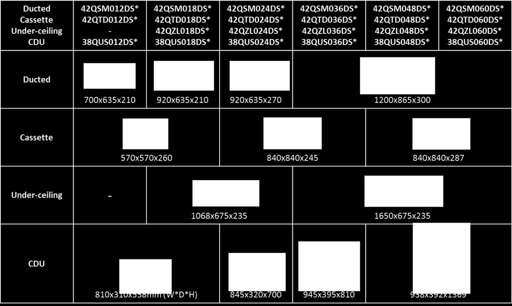
5 PRODUCT LINEUP 2
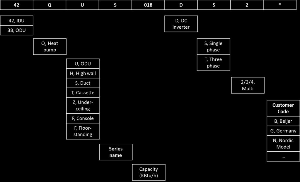
6 UNIT MODEL INDENTIFICATION 3
7 PART 1 GENERAL INFORMATION 1.1 DUCTED
8 K H G D C M W2 W1 J DIMENSIONS Air filter ( optional ) air inlet from rear side I H2 H1 4-install hanger L A Liquid side B 25 Drain pipe Gas side Test mouth & Test cover 25 Drain pipe 25 Drain connecting pipe ( for pump ) Electric control box Fresh air intake E F Air filter ( optional ) air inlet from bottom side te: standard product without filter Unit: mm Model Outline dimension(mm) Air outlet opening size Air return opening size Size of install hanger Size of refrigerant pipe A B C D E F G H I J K L M H1 H2 W1 W2 42QSM036/48/60DS* Fresh air intake joint 1
9 INSTALLTION SPACE 2
10 STATIC PRESSURE 3
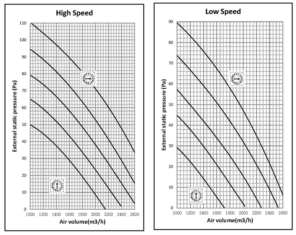
11 STATIC PRESSURE-42QSM036DS 4
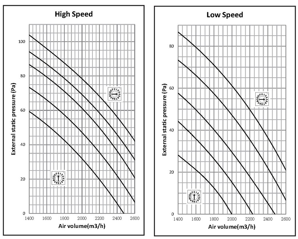
12 STATIC PRESSURE-42QSM048/060DS 5

 Disconnect the fan motor wire, fan")

 Screw off the screws to remove electronic control box")
 Disconnect the display board wire")
 Remove the sticker Sticker 3)Move the display board")
13 DISASSEMBLY INSTRUCTION. Parts name Procedures Remarks 1 Remove the electronic control box 1) Screw off the screws to remove the cover of electronic control box Four screws 2) Disconnect the fan motor wire, fan capacity wire, room temperature sensor wire and evaporator temperature sensor wire Plug of room temperate sensor and evaporator temperature sensor Fan motor wire Fan capacity wire 3) Screw off the screws to remove electronic control box 2 screws 2 Remove the display board 1) Remove the cover of electronic control box 2) Disconnect the display board wire connected to PCB Repeat the operation of step1 of 1 Connector 3) Remove the sticker Sticker 3)Move the display board according to the arrow direction to disassemble it. 6

 Remove the PCB from the electronic control")
 Remove the cover of electronic control box 2) Disconnect the")
 Screw off the screw to remover it Repeat the operation of step1 of 1 Repeat the")
14 3 Remove the PCB 1) Remove the cover of electronic control box 1) Pull out all the plugs or connectors connected to the PCB and remove the ground wire after remove the screw. Repeat the operation of step1 of 1 2) Remove the PCB from the electronic control box Press the four fixing holders from four corners to remove the PCB PCB 4 Remove the fan capacitor 1) Remove the cover of electronic control box 2) Disconnect the fan capacity wire. 3) Screw off the screw to remover it Repeat the operation of step1 of 1 Repeat the operation of step2 of 1 1 screw 5 Remover the fan motor 1) Screw off the fixing screws to remove the rear cover board 5 screws Rear cover board 7
 Remove the")
 Disassemble the fan motor fixing clamps to remove the fan motor")


15 2) Screw off the fixing screws to remove the rear beam Rear beam Total four screws at the left side and right side 3) Remove room temperature sensor Cut off the fastening belt to take off the room temperature sensor 4) Remove the sticker Stickers 5) Remove the below volute shell Press Press Press the clips to take off the volute shell 6) Remove the fan motor wire from the electronic control box 7) Disassemble the fan motor fixing clamps to remove the fan motor assembly and fan wheel assembly 8) Disassemble the fan wheels, then you can remove the fan motor Refer the operation of step2 of.1 The fan motor assembly and fan wheel assembly can be removed after took off the 2screws used to fix the fan motor holder. 6 Remove the water collector assembly 1) Remove the rear cover board 2) Screw off the screws to remove the water collector assembly Take off the screw to remove the fan wheel Repeat the operation of step1 of.5 4 screws 8

 Remove")


16 3 screws 3 screws 3 screws Water collector assembly 7 Remove the evaporator 1) Remove the water collector 2) Remove the evaporator sensor Repeat the operation of.6 Evaporator sensor 3) Remove the pipe clamp board 2 screws 4) Remove the evaporator support board 4 screws 9

17 5) Screw off the fixing screws to remove the evaporator 1 screw 10
18 PART 1 GENERAL INFORMATION 1.2 CASEETTE
19 DIMENSIONS D Fresh air intake A Wiring connection port A 32 Drain hole Test mouth & Test cover 840 C A B A A B A D B D D 4-install hanger Gas side Body Liquid side E-parts box A Service hole for draining pump B D D D D Panel Unit: mm Model A B C D 42QTD036DS* QTD048/60DS*
20 INSTALLTION SPACE 2


 Pic.1 Pic.")


")


21 DISASSEMBLY INSTRUCTION. Parts name Procedures Remarks 1 Remove the filter 1) Open the grille Use two fingers to press the clips on the grille (pic.1), then hitch the grille and open it (pic.2, pic.3) Pic.1 Pic.2 2) Remove the grille Disconnect the display board wire connected to the PCB. Move the grille up and down to remove the grille. Pic.3 Disconnect the wires between control box and grille Take down the grille from the clasps 3) Remove the filter Press the filter slightly according to the arrow direction to let filter free from the clasp, then you can take off it. Press following the arrow Clasp te: the filter is easy to be damaged, be careful when removing it. 2 Remove the 1) Open the grille Repeat the operation of step1 of. 1 3


 Remove the PCB from the fixing pins.")
 Open the grille Repeat")
22 display board 2) Remove the grille In order to prevent the grille falling down, it s necessary to remove it. 3) Disassemble the display board Remove the two screws show in the picture to disassemble the display board Repeat the operation of step2 of. 1 Two screws 3 Remove the PCB 1) Open the grille Repeat the operation of step1 of.1( need to remove the panel) 2) Disassemble the electronic control box cover Remove the 2 screws to 2 screws disassemble the electronic control box cover 3) Pull out all the plugs or connectors connected to the PCB 4) Remove the PCB from the fixing pins. There are white lines on the PCB to show the position of the pins. Fixing pin 4 Remove the electronic control box 1) Open the grille Repeat the operation of step1 of.1( need to take down the panel) 2) Remove the electronic Repeat the operation of step 2 of.3 control box cover 4
")


 2) Remove the electronic Repeat the")
23 3) Pull out all the plugs or connectors connected to the electronic control box 4) Remove the electronic control box Remove the 3 screws to disassemble the electronic control box 3 screws 5 Remove the panel 1) Open the grille Repeat the operation of step1 of.1 2) Remove the grille Repeat the operation of step2 of.1 3) Disassemble the four corner board Disassemble the corner board 6 Remove the volute shell 4) Loose the fixing screw to free the hooks. Screw 5) Move the four hooks from the clamps, then the panel can be disassembled. Hook Hook 1) Open the grille Repeat the operation of step1 of.1( need to take down the panel) 2) Remove the electronic Repeat the operation of.4 control box 3) Screw off the 3 screws to remove the volute shell 3 screws 5
 Remove the hexagon nut to disassemble the")
 Repeat the operation of.")
 Remove the 3 nuts to disassemble")
 Remove the panel Repeat the operation")

24 7 Remover the fan wheel 1) Repeat the operation of.6 2) Remove the hexagon nut to disassemble the fan wheel 3) Pull out the fan wheel 8 Remove the fan motor 1) Repeat the operation of.7 2) Remove the fixing board of fan motor wire Two screws 3) Remove the 3 nuts to disassemble the fan motor 3 nuts 9 Remove the water collector assembly 1) Remove the panel Repeat the operation of.5 2) Remove the electronic Repeat the operation of.4 control box 3) Remove the volute shell Repeat the operation of.6 6

 Rotate the")


 and")

 Take out the drain")
 Remove the water collector")
25 4) Screw off the screws to remove the water connector assembly 10 Remove the draining pump 1) Rotate the black cover counterclockwise to remove it. 2) Rotate the transparent cover counterclockwise to remove it with a special tool for it is very tighten. 3) Take off the fastening belt(or fixing clamp) and disconnect the water pipe Fastening belt Water pipe 4) Screw off the screws to remove the draining pump 3 screws 5) Take out the drain pump 11 Remove the evaporator 1) Remove the water collector assembly Repeat the operation of.9 7


26 2) Remove the seal board of evaporator Two screws 3) Remove the evaporator fixing board Six screws 4) Remove the evaporator fixing clamps to disassemble the evaporator. Two fixing clamps One screw 8
27 PART 1 GENERAL INFORMATION 1.3 UNDER-CEILING
28 DIMENSIONS 2-33 Wiring connection port 2-40 Drain discharge port 120 Fresh air intake B 204 Refrigerant pipe hole C A Hanging arm D MOdel A B C D 42QZL036/48/60DS*
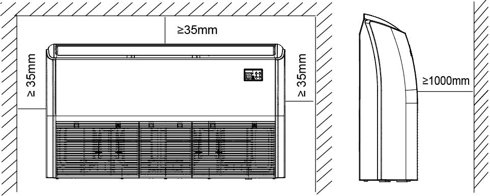
29 INSTALLTION SPACE 3


 Remove the air")


30 DISASSEMBLY INSTRUCTION. Parts name Procedures Remarks 1 Remove the 1) Pull the grille locker till air outlet the screws appears, and grilles. release these screws. 2) Remove the air return grille (watch the lockers under the grilles) Remove the control PCB 1) Release 2 screws fixing the control box, and then take it out. 2) Screw off the 2 screws to remove the cover of the control box 4

 Disconnect all the wires of plugs connected to the PCB")

 Remove the stickers stick to the volute")
31 Fan Capacitor Main PCB Transformer Power cord terminal 3) Disconnect the fan motor wire, louver motor wire, room temperature and evaporator temperature wire, and display board wire to remove the electronic control box 4) Disconnect all the wires of plugs connected to the PCB Indoor fan control Power input Input/output transformer of Control wires for outdoor unit To Display board Temperature Swing motor control sensors T1, T2 5) Remove the PCB from the fixing pins 3 Remove the fan motor and fan wheel 1) Remove the stickers stick to the volute shell Stickers 5


32 2) Remove the below volute shell Press Press the clips to take off the volute shell 3) Disassemble the fan motor fixing clamps to remove the fan motor assembly and fan wheel assembly The fan motor assembly and fan wheel assembly can be removed after took off the 2screws used to fix the fan motor fixing clamps. 4) Release the screws locking the fan wheel on the shaft, you can remove the fan wheels. Take off the screw to remove the fan wheel 6
 Release the 2 screws")

")

 Remove the front panel.")

")

33 4 Remove the display PCB 1) Release the 2 screws (both sides) and push the panel upwards to remove it Push it upwards Release the screw 2) Release 11 screws (5 at the front and 6 at both sides). 3) Remove the front panel. The display board is on the back. 4) Release 2 screws fixing the display PCB 5) Unplug the wires 5** Remove the vertical swing motor 1) Remove the drain pan assembly Release the 2 screws 7


 1) Remove the motor")

")


34 2) Remove the air outlet grille assembly by screwing of 8 screws 3) Release 2 screws fixing the swing motor to remove it release 8 screws 6 Remove 2 horizontal swing motors (on both sides off the unit) 1) Remove the motor protective cover 2) Screw off the 2 fixing screws to remove swing motor 2 screws 7 Remove the evaporator assembly 1) Remove the 4 screws (2 on left side and 2 on right side) fixing the evaporator on both sides of the unit. 2) Remove the evaporator 8
35 PART 1 GENERAL INFORMATION 1.4 OUTDOOR UNIT
36 DIMENSIONS Unit:mm Model A B C D E F H 38QUS036DS*
37 DIMENSIONS Unit:mm Model A B C D E F H 38QUS048/60DS*
38 INSTALLTION SPACE (Wall or obstacle) Air inlet More than 30cm Air inlet Air outlet More than 30cm Maintain channel More than 60cm More than 200cm More than 60cm 4
39 REFRIGENRANT CYCLE DIAGRAM INDOOR OUTDOOR LIQUID SIDE CAPILIARY TUBE Electronic expansion valve 2-WAY VALVE T3 Condenser temp. sensor HEAT EXCHANGE (EVAPORATOR) T2 Evaporator temp. sensor middle T1 Room temp. sensor T4 Ambient temp. sensor HEAT EXCHANGE (CONDENSER) T2B Evaporator temp. sensor outlet GAS SIDE 4-WAY VALVE 3-WAY VALVE Accumulator Compressor High pressure switch T5 Discharge temp. sensor Low pressure switch Oil separator COOLING Oil return Capillary HEATING 5
40 PART 2 ELECTRICAL DIAGRAM
41 WIRING DIAGRAM - 42QSM036/48/60DS 1
42 PCB SETTING - 42QSM036/48/60DS 2
43 WIRING DIAGRAM - 42QTD036/48/60DS 3
44 WIRING DIAGRAM - 42QZL036/48/60DS 4
45 WIRING DIAGRAM 38QUS036DS 5
46 WIRING DIAGRAM 38QUS048/60DT 6
47 PART 3 TROUBLE SHOOTING
48 SAFETY CAUTION Electricity power is still kept in capacitors even the power supply is shut off. Do not forget to discharge the electricity power in capacitor. Electrolytic Capacitors (HIGH VOLTAGE! CAUTION!) Connect discharge resistance (approx.100ω 40W) or soldering iron (plug) between +, - terminals of the electrolytic capacitor on the contrary side of the outdoor PCB. te: The picture above is only for reference. The plug of your side may be different. 1


49 ERROR CODE - IDU Display panel Cassette Under-ceiling Ducted 2
50 ERROR CODE - IDU Malfunction Error Code Timer Lamp Operation Lamp (flashes) Indoor EEPROM malfunction E0 X 1 Communication malfunction between indoor and outdoor units E1 X 2 Indoor fan speed is out of control E3 X 4 Open or short circuit of T1 temperature sensor E4 X 5 Open or short circuit of T2 temperature sensor E5 X 6 Refrigerant leakage detection EC X 7 Water level alarm EE X 8 Outdoor unit is faulty Ed X 11 Open or short circuit of T4 temperature sensor F1 O 2 Open or short circuit of T3 temperature sensor F2 O 3 Open or short circuit of T5 temperature sensor F3 O 4 Outdoor EEPROM malfunction (For some units) F4 O 5 Outdoor fan speed is out of control F5 O 6 Open or short circuit of T2B temperature sensor F6 O 7 IPM module malfunction P0 1 Over voltage or over low voltage protection P1 2 High temperature protection of top of compressor P2 3 Error rotor position protection of compressor P4 5 Low pressure protection of compressor P6 7 Sensor of outdoor IGBT is faulty P7 8 O (on) X(off) (flash at 2Hz) T1: Indoor room temperature T2: Coil temperature of indoor heat exchanger middle T2B: Coil temperature of indoor heat exchanger outlet T3: Coil temperature of condenser T4: Outdoor ambient temperature T5: Compressor discharge temperature 3

51 ERROR CODE - ODU Display Code Malfunction or Protection E0 Outdoor EEPROM malfunction E2 Communication error between indoor and outdoor units E3 Communication error between IPM board and outdoor main board E4 Open or short circuit of T3 or T4 temperature sensor E5 Voltage protection of compressor E8 Outdoor fan speed has been out of control P0 Top temperature protection of compressor P1 High pressure protection (Models specific) P2 Low pressure protection (Models specific) P3 Current protection of compressor P4 Discharge temperature protection of compressor P5 High temperature protection of condenser P6 IPM module protection P7 High temperature protection of evaporator In low ambient cooling mode, the LED displays LC or alternative displays between running frequency and LC (each displays 0.5s). T1: Indoor room temperature T2: Coil temperature of indoor heat exchanger middle T2B: Coil temperature of indoor heat exchanger outlet T3: Coil temperature of condenser T4: Outdoor ambient temperature T5: Compressor discharge temperature 4


52 Trouble Shooting - IDU E0/F4: Indoor EEPROM malfunction Malfunction decision Indoor or outdoor PCB main chip does not receive feedback from conditions EEPROM chip. Supposed causes Installation mistake PCB faulty Trouble shooting: Power off, then restart the unit 2 minutes later. Replace the indoor/outdoor main PCB. EEPROM: An electrically erasable programmable read-only memory whose contents can be erased and reprogrammed using a pulsed voltage. Indoor PCB Outdoor PCB te: The two photos above are only for reference, it s may be not same totally with the ones on your side. 5
53 E1: Communication error between indoor and outdoor units Malfunction decision Indoor unit does not receive the feedback from outdoor unit during 110 conditions seconds and this condition happens four times continuously. Supposed causes Wiring mistake Indoor or outdoor PCB faulty Power off, then turn on the unit 5 seconds later(reconnect the power wire).is the error still displaying after several minutes? Check if there s any interference. Such as too many lamps, power transformers? Or the signal wire is too long? Check whether the signal wire is shield cable or whether the shield cable is earthing? Remove interference. Increase the capacity of antiinterference Adopt shield cable/shield cable earthing. Check whether the wire is correct polarity? P to P, Q to Q, E to E? Correct the connection. Check whether the signal wire is broken? Replace the signal wire. Check whether the signal wires insert on main PCB well? Pull out and insert back. Replace indoor main PCB, is the error distinguished? Replace the outdoor main PCB. 6

54 E3: Indoor fan speed has been out of control Malfunction decision When indoor fan speed keeps too low (300RPM) for certain time, the unit conditions will stop and the LED will display the failure. Supposed causes Wiring mistake Fan ass y faulty Fan motor faulty PCB faulty Power off, then restart the unit 2 minupes later. Is it still displaying the error code? The unit operates normally. Shut off the power supply, rotate the fan by hand. Does it rotate properly? Find out the cause and have it solved. For example, whether the fan is blocked or the screws which fix the fan are tighten. Check the wiring of fan motor. Are all the connections good? Correct the connections. Check whether the main PCB is normal through index 1? Replace the main PCB Replace the fan motor Index 1: 1. Indoor DC fan motor (control chip is inside fan motor) Power on and when the unit is in standby, measure the voltage of pin1-pin3, pin4-pin3 in fan motor connector. If the value of the voltage is not in the range showing in below table, the PCB must have problems and need to be replaced. DC motor voltage input and output NO. Color Signal Voltage 1 Red Vs/Vm 200V~380V Black GND 0V 4 White Vcc V 5 Yellow Vsp 0~6.5V 6 Blue FG V 7
55 E4/E5/F1/F2/F3/F6: Open or short circuit of temperature sensor Malfunction decision If the sampling voltage is lower than 0.06V or higher than 4.94V, the LED conditions will display the failure. Supposed causes Wiring mistake Sensor faulty Check the connections between temperature sensor and PCB. Are the connections good? Correct the connections. Measure the resistance value of the sensor via Appendix 1 Is it normal? Replace the sensor. Replace the indoor PCB 8
56 EC: Refrigerant Leakage Detection Malfunction decision Define the evaporator coil temp.t2 of the compressor just starts running conditions as Tcool. In the beginning 5 minutes after the compressor starts up, if T2 <Tcool -2 does not keep continuous 4 seconds and this situation happens 3 times, the display area will show EC and AC will turn off. Supposed causes T2 sensor faulty Indoor PCB faulty Shut off the power supply and turn it on 2 minutes later. Is it still displaying the error code? System problems, such as leakage or blocking. Is there cool air blowing out from indoor air outlet? Check if T2 sensor is well fixed. Correct the installation or replace T2 sensor. Does the problem remain again? Is there any leakage? Especially the connection parts, such as the gas valve and the liquid valve. Replace indoor PCB. Is there any blocking? (Such as the capillary or the welded points of the pipes.) Repair the leakage and recharge the refrigerant. Clear the blocking. 9
57 EE: Water-level alarm malfunction Malfunction decision conditions Supposed causes If the sampling voltage is not 5V, the LED will display the failure. Wiring mistake Water-level switch faulty Water pump faulty Indoor PCB faulty Power off, then restart the unit 3 minutes later. Is it still displaying the error code? If the water-level switch is inserted well? Insert the water-level switch well If the water-level switch is broken? Replace the water-level switch Replace the water pump, If malfunction is still not solved Replace the indoor main PCB Ed: Outdoor unit malfunction Whether the outdoor main board has error displayed Power off, then restart the unit 2 minutes later. If the outdoor main board displays error code several minutes later? Refer to corresponding solving steps 10
58 P0: IPM malfunction or IGBT over-strong current protection Malfunction decision When the voltage signal that IPM send to compressor drive chip is conditions abnormal, the display LED will show P0 and AC will turn off. Supposed causes Wiring mistake; IPM malfunction; Outdoor fan ass y faulty Compressor malfunction; Outdoor PCB faulty Check the wiring between main PCB and compressor Correct the connection or replace the wires and connectors. Check the IPM Replace the IPM board or replace the main PCB Check the outdoor fan and the outdoor unit ventilation Please refer to the solution of Fan Speed Has Been Out Of Control malfunction Check the compressor resistance values Replace the compressor. Replace the outdoor main PCB 11
59 P1: Over voltage or too low voltage protection Malfunction decision An abnormal voltage rise or drop is detected by checking the specified conditions voltage detection circuit. Supposed causes Power supply problems. System leakage or block PCB faulty Check the power supply Stop the unit Check the connections and wires Correct the connections or replace the wires. Check the voltage between P and N Replace the IPM board Check the reactor Replace outdoor main PCB Replace the reactor 12
60 P2: High temperature protection of compressor top Malfunction decision If the sampling voltage is not 5V, the LED will display the failure. conditions Supposed causes Power supply problems. System leakage or block PCB faulty Check the air flow system of indoor and outdoor units Clear up the air inlet and outlet or the heat exchanger of indoor and outdoor units. Power off, then restart the unit 10 minutes later Check if the temperature of compressor Check the overload protector Correct the connection. Check refrigerant system Measure the resistance between the two ports of the OLP. Is it zero? Replace the OLP. Replace the outdoor control PCB. 13
61 P4: Inverter compressor drive error diagnosis and solution Malfunction decision An abnormal inverter compressor drive is detected by a special conditions detection circuit, including communication signal detection, voltage detection, compressor rotation speed signal detection and so on. Supposed causes Wiring mistake; IPM malfunction; Outdoor fan ass y faulty Compressor malfunction; Outdoor PCB faulty Check the wiring between main PCB and compressor Correct the connection or replace the wires and connectors. Check the IPM Replace the IPM board or replace the main PCB Check the outdoor fan and the outdoor unit ventilation Please refer to the solution of Fan Speed Has Been Out Of Control malfunction Check the compressor resistance values Replace the compressor. Replace the outdoor main PCB 14
62 Trouble Shooting - ODU E0: malfunction E0 display Outdoor EEPROM malfunction Power off, then restart the unit 2 minutes later Replace the outdoor main PCB EEPROM: An electrically erasable programmable read-only memory whose contents can be erased and reprogrammed using a pulsed voltage. E2: Communication error between indoor and outdoor units, Same as E1 of IDU. 15
63 E3: Communication error between IPM board and outdoor main board E3 display Communication malfunction between IPM board and outdoor main board Is there at least one LED in the IPM board light? Check the signal wire between the IPM board and the main board, is it connected good? Reconnect and retry. Is error still display? Replace IPM board, and then check whether the system can run normally Replace outdoor main board, and then check whether the system can run normally Replace the electric control box Trouble is solved 16
64 E4: Open or short circuit of T3 or T4 temperature sensor E4 display Judge 1: Outdoor condenser temp. sensor (T3) is malfunction Check whether the wiring of the condenser temp. sensor(t3) is broken off Connect the wiring well Check whether the resistance of condenser temp. sensort3) is wrong refer to the Appendix 1 Replace condenser temp. sensor(t3) Judge 2: Outdoor ambient temp. sensor (T4) is malfunction Check whether the wiring of the outdoor ambient temperature sensor (T4) is broken off Check whether the resistance of outdoor ambient temperature sensor (T4) is wrong refer to the Appendix 1 Connect the wiring well Replace outdoor ambient temperature sensor (T4) Judge 3: Compressor discharge temp. sensor (T5) is malfunction Check whether the wiring of the compressor discharge temperature sensor (T5) is broken off Connect the wiring well Check whether the resistance of compressor discharge temp. sensor (T5) is wrong refer to the Appendix 2 Replace compressor discharge temperature sensor (T5) Replace outdoor main PCB 17
65 E5: Voltage protection of compressor E5 display Voltage protection of compressor Check whether the power voltage is normal. Restart the unit when the power supply gets normal Measure whether outdoor terminal voltage is normal? Check the wiring of power wires well or correctly Reconnect it well Measure whether the voltage between L and N is normal? Check the wiring of L and N well or correctly Reconnect it well Measure whether input voltage of bridge rectifier is normal? Check the wiring of bridge rectifier well or correctly Reconnect it well Measure whether the voltage between P and N is normal refer to the Appendix 3? Check whether bridge rectifier is normal Replace the bridge rectifier Replace the PFC module(if has) Check the wiring of reactor or inductance Reconnect the wiring Replace the IPM board, If the IPM board and main board is in a board, replace the outdoor main PCB Check whether reactor or inductance is normal Replace reactor or inductance E8: Outdoor fan speed has been out of control, same trouble shooting as E3 of IDU. 18
66 P0: Top temperature protection of compressor Malfunction decision If the sampling voltage is not 5V, the LED will display the failure. conditions Supposed causes Power supply problems. System leakage or block PCB faulty P0 display Top temperature protection of compressor Check the air flow system of indoor and outdoor units Clear up the air inlet and outlet or the heat exchanger of indoor and outdoor units. Power off, then restart the unit 10 minutes later Check whether the temperature of compressor top is more than 100 Check wiring connection of the overload protector Correct the connection. Check the refrigerant volume charge Measure the resistance between the two ports of the OLP. Is it zero? Replace the OLP. Replace the outdoor main PCB. Refrigerant system is blocked, such as capillary or welded point of pipes. Recharge the correct refrigerant volume. 19
67 P1: High pressure protection (Models specific) t1 display High pressure protection Whether the wiring between the high pressure switch and main control board is connected well or correctly bo Connect it well Whether the high pressure protector is broken Method: Disconnect the plug. Measure the resistance of the high pressure protector, if the protector is normal the value is o, bo Replace high pressure protector Check whether the outdoor ambient temperature is higher than 50 bo Stop the unit Check if the outdoor unit ventilation is good bh Make the outdoor unit ventilate well Check if the outdoor fan runs properly bo please refer to the solution of fan speed has been out of control malfunction. Cind out the cause and have it solved. Check whether the heat exchanger is dirty Clean the heat exchanger bo Replace outdoor main board bo Check whether the refrigerant system is ok 20
68 P2: Low pressure protection (Models specific) P2 display Low pressure protection WhePher Phe wiring bepween Phe low pressure propecpor and main conprol board is connecped well or correcply bo Connect it well WhePher Phe low pressure propecpor is broken Method: Disconnect the plug. Measure the resistance of the low pressure protector. If the protector is normal the value is o bo Replace low pressure protector Check whepher Phe oupdoor ambienp PemperaPure is Poo low Stop the unit bo Check whether valve core of high pressure valve is opened Check if if the indoor fan runs properly in cooling mode bo bo Open fully valve core of high pressure valve please refer to the solution of fan speed has been out of control malfunction. Find out the cause and have it solved. Replace oupdoor main board bo wefrigerant is not enough add the refrigerant bo Check whether the refrigerant system is ok 21
69 P3: Current protection of compressor P3 display Current protection of compressor The protection occurred in standby Check whether the power voltage is normal. Restart the unit when the power supply gets normal Measure whether outdoor terminal voltage is normal? Check the wiring of power wires well or correctly Reconnect it well Measure whether the voltage between L and N is normal? Check the wiring of L and N well or correctly Reconnect it well Measure whether input voltage of bridge rectifier is normal? Check the wiring of bridge rectifier well or correctly Reconnect it well Measure whether the current is normal? Replace the outdoor main PCB Measure whether the voltage between P and N is normal refer to the Appendix 3? Check whether bridge rectifier is normal Replace the bridge rectifier Check whether the outdoor ambient temperature is higher than 50 Stop the unit Replace the PFC module(if has) Check if the outdoor unit ventilation is good Make the outdoor unit ventilate well Check the wiring of reactor or inductance Reconnect the wiring Check if the outdoor fan runs properly please refer to the solution of fan speed has been out of control malfunction. Find out the cause and have it solved. Check whether reactor or inductance is normal Replace reactor or inductance Check whether the heat exchanger is dirty Clean the heat exchanger Replace outdoor main board Check whether system pressure is too high Recycle the over charged refrigerant Check whether the refrigerant system is ok 22
70 P4: Discharge temperature protection of compressor When compressor discharge temperature is higher than 115 C, the unit will stop, and unit runs again when compressor discharge temperature is lower than 90 C. P4 display Temperature protection of compressor discharge Check whether the compressor discharge temp. is more than 115 C? Check whether the refrigerant is leak Stop leaking and add refrigerant bo bo Check whepher Phe connecpion is righp bepween compressor discharge Pemp. sensor and PCB according Po wiring diagrams? bo CorrecP Phe wiring connecpion Measure Phe resispance value of compressor discharge Pemp. sensor. If Phe value is nop normal is normal refer to the Appendix 2? bo Replace Phe compressor discharge Pemp. sensor Replace oupdoor main PCB bo Replace high pressure valve assy 23
71 P5: High temperature protection of condenser When condenser high temp. is more than 65 C, the unit will stop, and unit runs again when outdoor pipe temp. less than 52 C. P5 display High temperature protection of condenser Check the connection between temperature sensor and PC.. Correct the connection Check whepher Phe condenser PemperaPure is Higher Phan 65 C Check whepher Phe resispance of condenser Pemp. sensor is normal refer to the Appendix 1 weplace the temperature sensor Check whepher Phe oupdoor amnienp PemperaPure is higher Phan 50 Stop the unit Check if the outdoor unit ventilation is good Make Phe oupdoor unip venpilape well Check if the outdoor fan runs properly please refer to the solution of fan speed has been out of control malfunction. Cind out the cause and have it solved. Check whepher Phe heap exchanger is dirpy Clean Phe heap exchanger Replace oupdoor main ard wefrigerant is not enough add the refrigerant Check whepher Phe refrigeranp syspem is ok 24
72 P6: IPM module protection At first test the resistance between every two ports of U, V, W of IPM and P, N. If any result of them is 0 or close to 0, the IPM is defective. Otherwise, please follow the procedure below: P6 display IPM module protection Check whether the power voltage is normal. Restart the unit when the power supply gets normal Measure whether outdoor terminal voltage is normal? Check the wiring of power wires well or correctly Reconnect it it well Measure whether the voltage between L and N is normal? Check the wiring of L and N well or correctly Reconnect it it well Measure whether input voltage of bridge rectifier is normal? Check the wiring of bridge rectifier well or correctly Reconnect it it well Measure whether the voltage between P and N is normal refer to the Appendix 3? Check whether bridge rectifier is normal Replace the bridge rectifier Check whether the connecting wire between main board and the Lta board is connected tightly weconnect it well Replace the PFC module(if has) Check whether the connecting wire of the compressor is connected correctly or tightly weconnect it well Check the wiring of reactor or inductance Reconnect the wiring Check if if the outdoor unit ventilation is good Make the outdoor unit ventilate well Check if if the outdoor fan runs properly please refer to the solution of fan speed has been out of control malfunction. Find out the cause and have it it solved. Check whether reactor or inductance is normal Replace reactor or inductance Replace IPM board Replace the outdoor main PCB Check the compress is normal Replace the compressor Check whether the refrigerant system is ok 25
73 P7: High temperature protection of evaporator P7 display High temperature protection of evaporator Whether compressor operates? Check the connection between T2 and PCB. Check whether T2 and T2B Is reversed Correct the connection Check whether the outdoor ambient temperature is higher than 30 Stop the unit Check whether the resistance of T2 is normal refer to the Appendix 1 Replace the temperature sensor Check whether the air-outlet is blocked? Clean the air-outlet Check whether the indoor fan is running normal? please refer to the solution of fan speed has been out of control malfunction. Find out the cause and have it solved. Check whether the heat exchanger and filter are dirty? Clean the heat exchanger and filter Replace the indoor main PCB 26
74 APPENDIX 1 Temperature Sensor Resistance Value Table, B=4100K K Ohm K Ohm K Ohm K Ohm
75 APPENDIX 2 Compressor Discharge Temperature Sensor Resistance Value Table, B=3950K K Ohm K Ohm K Ohm K Ohm

")

 around 530VDC")
76 APPENDIX 3 In standby In operation With passive PFC module rmal voltage of P and N V(1-phase,3-phase) around 310VDC With partial active PFC module With fully active PFC module V(3-phase) around 530VDC >200VDC >310VDC >370VDC >450VDC / \ 29
SERVICE MANUAL 42QHF009DS* 42QHF012DS* 42QHF018DS* 42QHF022DS* 38QUS009DS* 38QUS012DS* 38QUS018DS* 38QUS022DS* Indoor unit.
 SERVICE MANUAL Indoor unit Outdoor unit 42QHF009DS* 42QHF012DS* 42QHF018DS* 42QHF022DS* 38QUS009DS* 38QUS012DS* 38QUS018DS* 38QUS022DS* INDEX PART1 GENERAL INFORMATION PART2 ELECTRICAL DIAGRAM PART3 TROUBLE
TROUBLESHOOTING TROUBLESHOOTING. Indoor unit EEPROM parameter error. Indoor / outdoor units communication error. Zero-crossing signal detection error
 www.olmo-comfort.com TROUBLESHOOTING When below list for identification of error code occurs, please turn off air conditioner and disconnect power, and then contact the qualified professionals for service.
FROZEN SERIE SERVICE MANUAL. DC Inverter R32. Sistemi per la climatizzazione
 DC Inverter R32 Sistemi per la climatizzazione SERVICE MANUAL FROZEN SERIE CONTENTS 1. General information of Outdoor Units... 3 2. Features... 4 3. Dimensions... 5 4. Refrigeration Cycle Diagram... 6
KMIR218-H221 / KMIR327-H217 / KMIR436-H217 / KMIR545-H219
 Multi outdoor units SERVICE MANUAL Multi - Zone heat pump units Model Numbers: KMIR218-H221 / KMIR327-H217 / KMIR436-H217 / KMIR545-H219 Table of Contents 1. Indoor Unit Combination 2. Suggested Indoor
DuctlessAire ES Series. Service Manual 2016 ABSSA-B4-1601
 DuctlessAire ES Series Service Manual 2016 ABSSA-B4-1601 CONTENTS 1. Precaution... 1 1.1 Safety Precaution... 1 1.2 Warning... 1 2. Model list... 4 3. Dimension... 5 3.1 Indoor Unit... 5 3.2 Outdoor Unit...
Multi zone. MULTI OUTDOOR UNITsS. CONDENsSING UNITsS. Revision V1.0: Table of Contents
 MULTI OUTDOOR UNITsS sservice MANUAL Multi zone CONDENsSING UNITsS Revision V1.0: 20160616 Table of Contents 1. Indoor Unit Combination 2. Suggested Indoor Unit Model Numbers 3. Dimension Of Outdoor Unit
SUPER DC INVERTER MULTI TYPE INSTRUKCJA SERWISOWA
 ODMFI-B-1211 INSTRUKCJA SERWISOWA SUPER DC INVERTER MULTI TYPE K2OD-14HFN1-Q, K2OD-18HFN1-Q, K3OD-21HFN1-Q K3OD-27HFN1-Q, K4OD-28HFN1-Q, K4OA-36HFN1-Q K5OC-36HFN1-Q DC MULTI OUTDOOR UNITS CONTENTS 1. General
Mission 3D Inverter Series
 Mission 3D Inverter Series Service Manual 2014 MBSEU-A-1412 CONTENTS 1. Precaution... 3 1.1 Safety Precaution... 3 1.2 Warning... 3 2. Function... 6 3. Dimension... 7 3.1 Indoor Unit... 7 3.2 Outdoor Unit...
YC ON-OFF SERIES. Service Manual
 YC ON-OFF SERIES Service Manual CONTENTS 1. Precaution... 3 1.1 Safety Precaution... 3 1.2 Warning... 3 2. Model Lists... 6 3. Dimension... 7 3.1 Indoor Unit... 7 3.2 Outdoor Unit... 11 4. Refrigerant
MULTI INVERTER SERIE H6M
 MULTI INVERTER SERIE H6M Service manual www.mundoclima.com Thank you very much for purchasing our products. Please read this manual carefully before installing and using the unit. ODMFI-B1-1606 CL20440
Dream Inverter Series. Service Manual 2017
 Dream Inverter Series Service Manual 2017 CONTENTS 1. Precaution... 3 1.1 Safety Precaution... 3 1.2 Warning... 3 2. Model List... 6 3. Dimension... 7 3.1 Indoor Unit... 7 3.2 Outdoor Unit... 11 4.Refrigerant
SERVICE MANUAL Room Air Conditioner DC Inverter Multi Split Outdoor units
 SERVICE MANUAL Room Air Conditioner DC Inverter Multi Split Outdoor units FS2MIF-140AE2 FS2MIF-180AE2 FS3MIF-210AE2 FS3MIF-270AE2 FS4MIF-280AE2 FS4MIF-360AE2 FS5MIF-360AE2 NOTE: Before servicing the unit,
15C Inverter Series. Service Manual
 15C Inverter Series Service Manual CONTENTS 1. Precaution... 1 1.1 Safety Precaution... 1 1.2 Warning... 1 2. Function... 4 3. Dimension... 5 3.1 Indoor Unit... 5 3.2 Outdoor Unit... 7 4. Wiring Diagram...
Part 3 Troubleshooting
 Part Troubleshooting What is in this part? This part contains the following chapters: Chapter See page Troubleshooting 2 Error Codes: Hydro-box 7 Error Codes: Outdoor Units Error Codes: System Malfunctions
HABITAT USER MANUAL TIN310**V33 TIN414**V33 TIN520**V33 TIN625**V33 TIN1036H2V02 TIN1939H2V02 INVERTER MINI SPLIT
 HABITAT INVERTER MINI SPLIT USER MANUAL TIN310**V33 TIN414**V33 TIN520**V33 TIN625**V33 TIN1036H2V02 TIN1939H2V02 WARNING The information contained in the manual is intended for use by a qualified service
Part 5. Troubleshooting. 1. Normal Air Conditioner Phenomenon Air Conditioner Protection in Common
 Part 5 1. Normal Air Conditioner Phenomenon... 1611 2. Air Conditioner Protection in Common... 1611 3. Malfunction Code and... 162 160 1. Normal Air Conditioner Phenomenon 1.1 When outdoor unit appears
SERVICE MANUAL. Room Air Conditioner Split Wall-Mounted Type
 SERVICE MANUAL Room Air Conditioner Split Wall-Mounted Type FSAIF-Pro-94AE2 / FSOAIF-Pro-94AE2 FSAIF-Pro-124AE2 / FSOAIF-Pro-124AE2 FSAIF-Pro-184AE2 / FSOAIF-Pro-184AE2 FSAIF-Pro-244AE2 / FSOAIF-Pro-244AE2
Vertu Plus 3D Inverter Series
 Vertu Plus 3D Inverter Series Service Manual 2015 VPSFI -A-1511 CONTENTS 1. Precaution... 3 1.1 Safety Precaution... 3 1.2 Warning... 3 2. Function... 6 3. Dimension... 7 3.1 Indoor Unit... 7 3.2 Outdoor
Service manual. MIV V4+ Mini
 DM12-01.01.05en Service manual MIV V4+ Mini DC INVERTER R410A (~220V, 50Hz, 1Ph) MVUH80A-VA1 Contents Part 1 General Information... 1 Part 2 Outdoor Units... 6 Part 3 Installation... 44 DM12-01.01.05en
SERVICE MANUAL. Room Air Conditioner Split Wall-Mounted Type
 SERVICE MANUAL Room Air Conditioner Split Wall-Mounted Type FSAIF-Pro-95AE2 / FSOAIF-Pro-95AE2 FSAIF-Pro-125AE2 / FSOAIF-Pro-125AE2 FSAIF-Pro-185AE2 / FSOAIF-Pro-185AE2 FSAIF-Pro-245AE2 / FSOAIF-Pro-245AE2
YN-M SERIES MULTI SPLIT SYSTEM MULTI CIRCUIT OUTDOOR UNITS (2, 3 AND 4 ZONES) SERVICE MANUAL PRE 2014 MODELS (Pre Serials) CONDENSING UNITS
 SERVICE MANUAL PRE 2014 MODELS (Pre Serials) CONDENSING UNITS") YN-M SERIES MULTI SPLIT SYSTEM MULTI CIRCUIT OUTDOOR UNITS (2, 3 AND 4 ZONES) SERVICE MANUAL PRE 2014 MODELS (Pre 50130047 Serials) CONDENSING UNITS Parker Davis HVAC International, Inc. Revision B: ODMI
YN-M SERIES MULTI SPLIT SYSTEM MULTI CIRCUIT OUTDOOR UNITS (2, 3 AND 4 ZONES) SERVICE MANUAL PRE 2014 MODELS (Pre 50130047 Serials) CONDENSING UNITS Parker Davis HVAC International, Inc. Revision B: ODMI
Service Manual CAUTION ! WARNING SAFETY CONSIDERATIONS INTRODUCTION. 38MA*R Outdoor Unit Single Zone Ductless System Sizes 09 to 36
 38MA*R Outdoor Unit Single Zone Ductless System Sizes 09 to 36 Service Manual TABLE OF CONTENTS PAGE SAFETY CONSIDERATIONS... 1 INTRODUCTION... 1 MODEL / SERIAL NUMBER NOMENCLATURES... 2 SPECIFICATIONS...
KSIM20912-H216 KSIM30912-H216 KSIM40912-H216
 SERVICE MANUAL KLIMAIRE AIRCONDITIONER KSIM DC INVERTER MULTI TYPE KSIM20912-H216 KSIM30912-H216 KSIM40912-H216 DC MULTI OUTDOOR UNITS CONTENTS 1. General information of Outdoor Units...3 2 Features...4
INVERTER SERIE H6 Service manual
 INVERTER SERIE H6 Service manual MUPR-H6 www.mundoclima.com Thank you very much for purchasing our products. Please read this manual carefully before installing and using the unit. AESFI-A-1509 CL20015
Service Manual for TAS-18EHN, TAS-24EHN
 Service Manual for TAS-18EHN, TAS-24EHN CONTENTS 1. Precaution... 3 1.1 Safety Precaution... 3 1.2 Warning... 3 2. Function... 7 3. Dimension... 8 3.1 Indoor Unit... 8 3.2 Outdoor Unit... 10 4. Refrigerant
Service Manual CAUTION ! WARNING INTRODUCTION. 619PB High Wall Ductless System Sizes 09 to 36
 619PB High Wall Ductless System Sizes 09 to 36 Service Manual TABLE OF CONTENTS PAGE SAFETY CONSIDERATIONS... 1 INTRODUCTION... 1 MODEL/SERIAL NUMBER NOMENCLATURES... 2 SPECIFICATIONS... 3 COMPATIBILITY...
Bosch Split-Type Ductless Air Conditioner / Heat Pump
 Bosch Split-Type Ductless Air Conditioner / Heat Pump Climate 5000 AA Series Service Manual 2 Bosch Climate 5000 AA Series Split Type Ductless Air Conditioner / Heat Pump Service Manual Data subject to
Light Commercial SUPER INVERTER SERIES MULTI TYPE
 Light Commercial SUPER INVERTER SERIES MULTI TYPE Service Manual 2017 CONTENTS 1. General information of Indoor Units... 1 2. Features... 2 3. Dimensions... 12 4. Service Space (unit: mm)... 19 5. Wiring
The breaker trips at once when it is set to ON. The breaker trips in few minutes when it is set to ON.
 Trip of breaker or The breaker trips at once when it is set to O. Measure insulation resistance to ground to see if there is any leakage. Air conditioner can not start up blow of fuse The air conditioner
KDIR TROUBLESHOOTING. Middle Static Pressure Duct Type SERIES
 Middle Static Pressure Duct Type KDIR SERIES Thank you very much for purchasing our air conditioner, Before using your air conditioner, please read this manual carefully and keep it for future reference.
SERVICE MANUAL. Spilt Air Conditioner unit Ceiling & Floor Type FSPI-180AE1 / FSOIF-180AE1 FSPI-240AE1 / FSOIF-240AE1
 SERVICE MANUAL Spilt Air Conditioner unit Ceiling & Floor Type FSPI-180AE1 / FSOIF-180AE1 FSPI-240AE1 / FSOIF-240AE1 FI_SM_FSPI-180-240-AE1_20131010 1 Part 1 Indoor units 1. Features... 3 2. Dimensions...
Service Manual AIR CONDITIONER
 Service Manual AIR CONDITIONER DC INVERTER MULTI TYPE This manual applies to models: High Wall Duct Cassette Console Universal CDU 42QHF009DS 42QHF012DS 42QHF018DS 42QSM009DS 42QSM012DS 42QSM018DS 42QTD009DS
Multi zone Two, Three, Four and Five Zones
 MULTI SPLIT SYSTEM OUTDOOR UNITS SERVICE MANUAL Multi zone Two, Three, Four and Five Zones DC INVERTER MULTI ZONE OUTDOOR UNITS Revision A: ODMI E 1601 PDB55/2016 Model Numbers: YN020GMFI22M2D YN030GMFI22M3D
Troubleshooting & Reference
 Troubleshooting & Reference Error Code Descriptions Description of Error Codes - 9, 12 MBH code malfunction Error Display Repair Method 1 Storage slug (EEPROM) 2 Indoor PCB malfunction 3 Anti-freezing
F SERIES ON-OFF SERIES. Service Manual 2016
 F SERIES ON-OFF SERIES Service Manual 2016 CONTENTS 1. Precaution... 3 1.1 Safety Precaution... 3 1.2 Warning... 3 2. Function... 6 3. Dimension... 7 3.1 Indoor Unit... 7 3.2 Outdoor Unit... 9 4. Refrigerant
DCH DCI Series R410A HEATPUMP REFRIGERANT
 DCH DCI Series Indoor Units Outdoor Units JOSI-DCH009-N11 JSP023054 JOAU-DCY009-H11 JSP062910 JOSI-DCH012-N11 JSP023055 JOAU-DCY012-H11 JSP062911 JOSI-DCH018-N11 JSP023056 JOAU-DCY018-H11 JSP062912 JOSI-DCH024-N11
Room Air Conditioner Service and Parts Manual
 Cool Dry Temp Mode Room Air Conditioner Service and Parts Manual F Fan Speed hr Timer 0n 0ff Money Saver Fan Only Auto Swing Power CP06 CP08 93011401_01 CONTENTS 1. PREFACE 1.1 SAFETY PRECAUTIONS...2 1.2
CAUTION DLFEHA. SERVICE MANUAL High Wall Ductless System Sizes 09 to 24
 DLFEHA SERVICE MANUAL High Wall Ductless System Sizes 09 to 24 TABLE OF CONTENTS PAGE SAFETY CONSIDERATIONS... 1 INTRODUCTION... 1 MODEL/SERIAL NUMBER NOMENCLATURES... 2 SPECIFICATIONS COOLING ONLY...
SPLIT TYPE ROOM AIR CONDITIONER FLOOR CONSOLE / UNDER CEILING DUAL TYPE
 SPLIT TYPE ROOM AIR CONDITIONER FLOOR CONSOLE / UNDER CEILING DUAL TYPE Indoor unit ABYF8LAT ABYF8LAT ABYF8LAT ABYF8LAT ABYF8LBT ABYF8LBT ABYFLAT ABYFLAT ABYFLAT ABYFLAT ABYFLBT ABYFLBT Outdoor unit AOYA8LACL
LUNA INVERTER SERIES. Service Manual ASI-A-1301
 LUNA INVERTER SERIES Service Manual 2013 9ASI-A-1301 CONTENTS 1. Precaution... 3 1.1 Safety Precaution... 3 1.2 Warning... 3 2. Function... 7 3. Dimension... 8 3.1 Indoor Unit... 8 3.2 Outdoor Unit...
Room Air Conditioner CP06 & CP08. Chill 115 Volts. Service & Parts Manual THE EXPERTS IN ROOM AIR CONDITIONING _02
 Room Air Conditioner Service & Parts Manual 2014-2015 CP06 & CP08 Chill 115 Volts THE EXPERTS IN ROOM AIR CONDITIONING 93011401_02 CONTENTS 1. PREFACE 1.1 SAFETY PRECAUTIONS...2 1.2 INSULATION RESISTANCE
Mono 3D. SMART Inverter Air Conditioner SERVICE MANUAL. Revision A: , Content updated.
 z SMART Inverter Air Conditioner SERVICE MANUAL Mono 3D Revision A: 160003001, Content updated. Table of Contents 1. Precaution 2. Part Names And Functions 3. Dimension 4. Refrigerant Cycle Diagram 5.
SERVICE Manual FREE JOINT MULTI AIR CONDITIONER
 FREE JOINT MULTI AIR CONDITIONER INDOOR UNIT MH020FPEA MH023FPEA MH026FPEA MH035FPEA MH052FPEA MH8VP2-09 MH9VP2-07 MH9VP2-2 MH026FKEA MH035FKEA MH052FDEA OUTDOOR UNIT MH8VP2X MH9VP2X MH052FXEA2 MH068FXEA4
INSTRUKCJA SERWISOWA 12F INVERTER SERIES. Service Manual FSI-A-1310
 INSTRUKCJA SERWISOWA 12F INVERTER SERIES Service Manual 2013 12FSI-A-1310 CONTENTS 1. Precaution... 3 1.1 Safety Precaution... 3 1.2 Warning... 3 2. Function... 7 3. Dimension... 8 3.1 Indoor Unit... 8
INSTALLATION INSTRUCTIONS R 410A
 R 410A Ductless Split System Air Conditioner and Heat Pump MODELS: DLC4(A/H) Outdoor, DLF4(A/H) SIZES: 9K, 12K, 18K, 24K, 30K, and 36K NOTE: Read the entire instruction manual before starting the installation.
CASSETTE type INVERTER MULTI AIR CONDITIONER. Models AUY12LBAB AUY14LBAB AOY18LMAK2
 INVERTER MULTI AIR CONDITIONER CASSETTE type Models Indoor unit AUY12LBAB AUY14LBAB Outdoor unit AOY18LMAK2 CONTENTS SPECIFICATIONS..................... 1 OUTLINE AND DIMENSIONS........... 2 REFRIGERANT
Wired Controller XK60
 Owner's Manual Commercial Air Conditioners Thank you for choosing Commercial Air Conditioners, please read this owner s manual carefully before operation and retain it for future reference. User Notice
Service Manual CAUTION. 40MBDQ Ducted Style Ductless System Sizes 18 to 48 ! WARNING
 40MBDQ Ducted Style Ductless System Sizes 18 to 48 Service Manual TABLE OF CONTENTS PAGE SAFETY CONSIDERATIONS... 1 INTRODUCTION... 1 MODEL SERIAL NUMBER NOMENCLATURES... 2 SPECIFICATIONS... 3 COMPATIBILITY...
RC-54CA RO-50CA RC-54HA RO-50HA. SPLIT TYPE AIR CONDITIONER CASSETTE TYPE (50Hz) Indoor unit Outdoor unit
 Indoor unit Outdoor unit") SPLIT TYPE AIR CONDITIONER CASSETTE TYPE (50Hz) Indoor unit Outdoor unit RCW-54CB RO-50CA RC-54CA RO-50CA RC-54HA RO-50HA CONTENTS SPECIFICATIONS OUTLINE AND DIMENTIONS CIRCUIT DIAGRAM REFRIGERANT SYSTEM
SPLIT TYPE AIR CONDITIONER CASSETTE TYPE (50Hz) Indoor unit Outdoor unit RCW-54CB RO-50CA RC-54CA RO-50CA RC-54HA RO-50HA CONTENTS SPECIFICATIONS OUTLINE AND DIMENTIONS CIRCUIT DIAGRAM REFRIGERANT SYSTEM
Owner s Manual Super-Slim Four-Way Cassette
 CASSETTE- TYPE AIR CONDITIONER Owner s Manual Super-Slim Four-Way Cassette IMPORTANT NOTE: Read this manual carefully before installing or operating your new air conditioning unit. Make sure to save this
Installation Instructions
 40MBFQ Floor Console Ductless System Sizes 09 to 58 Installation Instructions TABLE OF CONTENTS PAGE SAFETY CONSIDERATIONS... 2 PARTS LIST... 3 SYSTEM REQUIREMENTS... 4 WIRING... 4 DIMENSIONS... 5 CLEARANCES...
SPLIT TYPE ROOM AIR CONDITIONER CEILING TYPE (60Hz)
") SPLIT TYPE ROOM AIR CONDITIONER CEILING TYPE (60Hz) Indoor unit MS6YF Outdoor unit MR6YF CONTENTS SPECIFICATIONS... OUTLINE AND DIMENSIONS... REFRIGERANT SYSTEM DIAGRAM.... CIRCUIT DIAGRAM... INDOOR PCB
SPLIT TYPE ROOM AIR CONDITIONER CEILING TYPE (60Hz) Indoor unit MS6YF Outdoor unit MR6YF CONTENTS SPECIFICATIONS... OUTLINE AND DIMENSIONS... REFRIGERANT SYSTEM DIAGRAM.... CIRCUIT DIAGRAM... INDOOR PCB
Service Manual & Installation Manual
 GE Consumer & Industrial Appliances Service Manual & Installation Manual Split System Air Conditioner Model numbers: GE AIR F24 GE AIR F34 GE AIR F41 1 2 3 Introduction and Features Model Remarks GE AIR
SERVICE MANUAL Room Air Conditioner Multi Split Type Indoor units Light Commercial Series
 SERVICE MANUAL Room Air Conditioner Multi Split Type Indoor units Light Commercial Series FSKMIF-71AE2-EU FSKMIF-91AE2-EU FSKIF-121AE2-EU FSKMI-181AE2-EU FSLMIF-71AE2 FSLMIF-91AE2 FSLIF-121AE2 FSLMI-180AE2
3.2 E1 Outdoor Unit PCB Abnormality E4 Actuation of Low Pressure Sensor E5 Compressor Motor Lock 3 52
 Error Codes: Outdoor Units Error Codes: Outdoor Units Part. What Is in This Chapter? Introduction Overview In the first stage of the troubleshooting sequence, it is important to correctly interpret the
CEILING type (60Hz) SPLIT TYPE ROOM AIR CONDITIONER CONTENTS. Models
 SPLIT TYPE ROOM AIR CONDITIONER CONTENTS. Models") SPLIT TYPE ROOM AIR CONDITIONER CEILING type (60Hz) Models Indoor unit ABU6RSLX Outdoor unit AOU6RLX CONTENTS SPECIFICATIONS....................... OUTLINE AND DIMENSIONS............. REFRIGERANT SYSTEM
SPLIT TYPE ROOM AIR CONDITIONER CEILING type (60Hz) Models Indoor unit ABU6RSLX Outdoor unit AOU6RLX CONTENTS SPECIFICATIONS....................... OUTLINE AND DIMENSIONS............. REFRIGERANT SYSTEM
SERVICE MANUAL SPLIT WALL-MOUNTED TYPE MODELS MWCOHC30S/MRCOHC30AS MWCOHC36S/MRCOHC36AS
 SERVICE MANUAL SPLIT WALL-MOUNTED TYPE MODELS MWCOHC30S/MRCOHC30AS MWCOHC36S/MRCOHC36AS CONTENTS 1. Precaution... 1 1.1 Safety Precaution... 1 1.2 Warning... 1 2. Function... 6 3. Dimension... 7 3.1 Indoor
Automatic Ice Maker. Service Manual VT ICEMAKER 15
 Automatic Ice Maker Service Manual VT ICEMAKER 15 Table of contents How the Icemaker works 3 10 Cooling System 3 Water System 4 5 Wiring Connections and Controller 6 8 Exploding Drawing 9 10 TroubleShooting
FLOOR CONSOLE / UNDER CEILING DUAL type
 SPLIT TYPE ROOM AIR CONDITIONER FLOOR CONSOLE / UNDER CEILING DUAL type Models Indoor unit ABU8RULX ABURULX Outdoor unit AOU8RLX AOURLX CONTENTS SPECIFICATIONS... OUTLINE AND DIMENSIONS... REFRIGERANT
KSIN INVERTER SERIES Service Manual 2013
 KSIN INVERTER SERIES Service Manual 2013 CONTENTS 1. Precaution............ 1 1.1 Safety Precaution... 1 1.2 Warning... 1 2. Function............ 6 3. Dimension............ 8 3.1 Indoor Units... 8 3.2
Owner s Manual. Middle Static Pressure Duct Type MEU-18MPH2 MEU-24MPH2 MEU-36MPL2 MEU-48MPL2 MIDDLE STATIC PRESSURE DUCT TYPE AIR CONDITIONER
 MIDDLE STATIC PRESSURE DUCT TYPE AIR CONDITIONER Owner s Manual Middle Static Pressure Duct Type MEU-18MPH2 MEU-24MPH2 MEU-36MPL2 MEU-48MPL2 IMPORTANT NOTE: Read this manual carefully before installing
Westinghouse. Split System Inverter Series. Service Manual
 Westinghouse Split System Inverter Series Service Manual Model: WIWPK/WCHPK Range: 2.6kw 7.6kw CONTENTS 1. Precaution... 1 1.1 Safety Precaution... 1 1.2 Warning... 1 2. Function... 5 3. Dimension... 6
DUCT type. Большая библиотека технической документации каталоги, инструкции, сервисные мануалы, схемы.
 SPLIT TYPE AIR CONDITIONER (50Hz) DUCT type Models Indoor unit Outdoor unit RD-25CA RD-25HA RD-30CA RD-30HA RO-25CA RO-25HA RO-30CA RO-30HA C O N T E N T S SPECIFICATIONS.............................................
Installation Instructions
 40MAQ High Wall Ductless Split System Sizes 09 to 36 Installation Instructions NOTE: Read the entire instruction manual before starting the installation TABLE OF CONTENTS PAGE SAFETY CONSIDERATIONS 2 PARTS
Service Manual CAUTION
 38MHR Outdoor Unit Single Zone Ductless System Sizes 09 to 24 Service Manual TABLE OF CONTENTS PAGE SAFETY CONSIDERATIONS... 1 INTRODUCTION... 1 MODEL/SERIAL NUMBER NOMENCLATURES... 2 SPECIFICATIONS...
CASSETTE type INVERTER MULTI AIR CONDITIONER
 INVERTER MULTI AIR CONDITIONER CASSETTE type Models Indoor unit AUY12LBAB AUY14LBAB Outdoor unit AOY18LMAK2 CONTENTS SPECIFICATIONS..................... 1 OUTLINE AND DIMENSIONS........... 2 REFRIGERANT
TECHNICAL & SERVICE MANUAL. Ceiling Concealed
 STAND BY DEFROST CHECK CLOCK ON OFF NOT AVAILABLE FILTER CHECK MODE TEST RUN FUNCTION SPLIT-TYPE, HEAT PUMP AIR CONDITIONERS TECHNICAL & SERVICE MANUAL Series SEZ Ceiling Concealed R40A.OC0 REVISED EDITION-A
Installation Instructions
 40MBFQ Floor Console Ductless System Sizes 09 to 12 Installation Instructions TABLE OF CONTENTS PAGE SAFETY CONSIDERATIONS... 2 PARTS LIST... 3 SYSTEM REQUIREMENTS... 4 DIMENSIONS... 5 CLEARANCES... 5
60Hz R410A ON/OFF CONDENSING UNIT MODEL: MTVCN. Service Manual Contents
 60Hz R410A ON/OFF CONDENSING UNIT MODEL: MTVCN Service Manual 2016 Contents i Refrigerant pipe installation Outdoor unit installation (Top Discharge Unit) 4.1 Location selection Before starting the installation,
Room Air Conditioner Service and Parts Manual
 Cool Dry Mode Temp Room Air Conditioner Service and Parts Manual 0F Fan Speed hr Timer 0n/0ff Money Saver Fan Only Auto Swing Power CP10 CP12 CP10 - CP12 (06/14) 93011402_04 CONTENTS 1. PREFACE 1.1 SAFETY
NORTH AMERICAN HVAC PRODUCTS LTD 3208 BETA AVE, BURNABY BC V5G 4K4 CSNA-1305-A SERVICE MANUAL AIR CONDITIONER SPLIT WALL-MOUNTED TYPE.
 NORTH AMERICAN HVAC PRODUCTS LTD 3208 BETA AVE, BURNABY BC V5G 4K4 CSNA-1305-A SERVICE MANUAL AIR CONDITIONER SPLIT WALL-MOUNTED TYPE Corona Series CONTENTS 1. Precaution... 1 1.1 Safety Precaution...
1. Dimensions Service Space Piping Diagrams Wiring Diagrams Electric Characteristics...
 Outdoor Units Part 3 Outdoor Units 1. Dimensions... 119 2. Service Space...122 3. Piping Diagrams...123 4. Wiring Diagrams...126 5. Electric Characteristics...133 6. Operation Limits...134 7. Sound Levels...135
SEER 15 DC INVERTER SERIES
 NORTH AMERICAN HVAC PRODUCTS LTD Address: 3208 Beta Ave, Burnaby BC Canada V5G 4K4 Tel: 604-4308496 Fax: 1-866-9034371 WWW.NORTHAMERICANHVAC.COM SEER 15 DC INVERTER SERIES Service Manual 2013 SINGLE ZONE
Código de Erros Split Piso Teto
 Código de Erros Split Piso Teto No. Type Description Flash Blink Code Note 1 Failure Indoor temp. sensor testing port warning Timer led blinks on 1Hz frequency E2 2 Failure 3 Failure 4 Failure Evap. temp.
CASSETTE type (50Hz) SPLIT TYPE AIR CONDITIONER. Models Indoor unit Outdoor unit
 SPLIT TYPE AIR CONDITIONER. Models Indoor unit Outdoor unit") SPLIT TYPE AIR CONDITIONER CASSETTE type (50Hz) Models Indoor unit Outdoor unit RCW-12HA RO-12HB C O N T E N T S SPECIFICATIONS........................................ 1 OUTLINE AND DIMENSIONS..............................
SPLIT TYPE AIR CONDITIONER CASSETTE type (50Hz) Models Indoor unit Outdoor unit RCW-12HA RO-12HB C O N T E N T S SPECIFICATIONS........................................ 1 OUTLINE AND DIMENSIONS..............................
FLOOR CONSOLE / UNDER CEILING DUAL type (60Hz)
") SPLIT TYPE ROOM AIR CONDITIONER FLOOR CONSOLE / UNDER CEILING DUAL type (60Hz) Models Indoor unit MSYF Outdoor unit MRUYF CONTENTS SPECIFICATIONS... OUTLINE AND DIMENSIONS... REFRIGERANT SYSTEM DIAGRAM...
SPLIT TYPE ROOM AIR CONDITIONER FLOOR CONSOLE / UNDER CEILING DUAL type (60Hz) Models Indoor unit MSYF Outdoor unit MRUYF CONTENTS SPECIFICATIONS... OUTLINE AND DIMENSIONS... REFRIGERANT SYSTEM DIAGRAM...
Technical Support Division GD CHIGO HEATING & VENTILATION EQUIPMENT CO., LTD.
 Technical Support Division 2017-4-25 New CMV System - Floor ceiling Indoor Unit 1 1. External appearance 2. Nomenclature 3. Specifications 4. Dimensions 5. Service space 6. Piping diagram 7. Wiring diagram
WALL MOUNTED type SPLIT TYPE ROOM AIR CONDITIONER CONTENTS. Models
 SPLIT TYPE ROOM AIR CONDITIONER WALL MOUNTED type Models Indoor unit ASY9USCCW ASY9USCCW ASY12USCCW Outdoor unit AOY9USCC AOY9UFCC AOY12USCC CONTENTS SPECIFICATIONS................................... 1
GREE ELECTRIC APPLIANCES, INC. OF ZHUHAI
 Change for life Models: GFH(09)EA-K6DNA1B/I GFH(12)EA-K6DNA1B/I GFH(18)EA-K6DNA1B/I GFH(21)EA-K6DNA1B/I Models: GFH(24)EA-K6DNA1B/I (Refrigerant R32) GREE ELECTRIC APPLIANCES, INC. OF ZHUHAI Table of Contents
CAUTION DLFPHA. SERVICE MANUAL High Wall Ductless System Sizes 09 to 12 ! WARNING
 DLFPHA SERVICE MANUAL High Wall Ductless System Sizes 09 to 12 TABLE OF CONTENTS PAGE SAFETY CONSIDERATIONS... 1 INTRODUCTION... 1 MODEL/SERIAL NUMBER MENCLATURES... 2 SPECIFICATIONS... 3 COMPATIBILITY...
Service Manual CAUTION. 38MAQ Outdoor Unit Single Zone Ductless System Sizes 09 to 30 ! WARNING SAFETY CONSIDERATIONS
 38MAQ Outdoor Unit Single Zone Ductless System Sizes 09 to 30 TABLE OF CONTENTS PAGE SAFETY CONSIDERATIONS... 1 INTRODUCTION... 1 MODEL/SERIAL NUMBER NOMENCLATURES... 2 SPECIFICATIONS... 3 DIMENSIONS...
Warning: 230V / 1ph / 50Hz V / 3ph / 50Hz. Remarks: Make sure that you have enough power. (See page 15 Cable table)
") 1 2 Warning: - Do not place your hand or any other objects into the air outlet and fan. It could damage the heat pump and cause injuries; - In case of any abnormality with the heat pump, cut off the power
1 2 Warning: - Do not place your hand or any other objects into the air outlet and fan. It could damage the heat pump and cause injuries; - In case of any abnormality with the heat pump, cut off the power
SERVICE MANUAL MUZ-DM25VA - E1, ER1, ET1 MUZ-DM35VA - E1, ER1, ET1 OUTDOOR UNIT. No. OBH751. Models HFC R410A
 OUTDOOR UNIT SERVICE MANUAL HFC utilized R410A. Models MUZ-DM25VA - E1, ER1, ET1 MUZ-DM35VA - E1, ER1, ET1 Indoor unit service manual MSZ-DM VA Series (OBH750) CONTENTS 1. TECHNICAL CHANGES 2 2. PART NAMES
Installation Instructions
 40MBCQ Cassette Ductless System Sizes 09 to 8 Installation Instructions TABLE OF CONTENTS PAGE SAFETY CONSIDERATIONS... PARTS LIST... 3 SYSTEM REQUIREMENTS... 4 DIMENSIONS INDOOR... 5 CLEARANCES INDOOR...
Table of Contents. Page. 1. Safety Precautions Specifications Product Features Maintenance and Disassembly...
 Table of Contents Page 1. Safety Precautions... 1 1. In case of Accidents or Emergency 2. Pre-Installation and Installation 3. Operation and Maintenance 2. Specifications... 3 1. Model Reference 2. Electrical
MODEL: CCT 301 INV CCT 501 INV CCT 70 INV-S CCT 100 INV-S CCT 140 INV-S CCT 170 INV-S
 MODEL: CCT 301 INV CCT 501 INV CCT 70 INV-S CCT 100 INV-S CCT 140 INV-S CCT 170 INV-S Compact Four-way Cassette Type 1. Features... 2. Specification... 3. Dimension... 4. Service Space... 5. Wiring Diagram...
4. Disassembly and Reassembly
 4. Disassembly and Reassembly Stop operation of the air conditioner and remove the power cord before repairing the unit. 4-1 Indoor Unit 4-1-1 MH FPEA /MH VP2-1 Front Panel 1) Stop the air conditioner
DUCTED AIR CONDITIONER. Owner s Manual. KD Series KD24. Kaden Owner s Manual 1
 DUCTED AIR CONDITIONER Owner s Manual KD Series KD24 Kaden Owner s Manual 1 Table of Contents 1. Safety Precautions 4 2. Indoor Unit Parts and Major Functions 6 3. Care and Maintenance 8 4. Troubleshooting
FIXED SPEED SERIES - 50 HERTZ 2017 SERVICE MANUAL
 FIXED SPEED SERIES - 50 HERTZ 2017 SERVICE MANUAL Table of Contents Page 1. Safety Precautions... 1 1. In case of Accidents or Emergency 2. Pre-Installation and Installation 3. Operation and Maintenance
KSD-35 DR11 KUE-35 DVN11
 FLOOR-STANDING TYPE AIR CONDITIONER Owner s Manual Floor-Standing Type KSD-35 DR11 KUE-35 DVN11 IMPORTANT NOTE: Read this manual carefully before installing or operating your new air conditioning unit.
Room Air Conditioner EP08 & EP12. Chill 115 Volts-EP Volts-EP12. Service & Parts Manual THE EXPERTS IN ROOM AIR CONDITIONING
 Room Air Conditioner Service & Parts Manual 2014-2015 EP08 & EP12 Chill 115 Volts-EP08 230 Volts-EP12 THE EXPERTS IN ROOM AIR CONDITIONING 93011407_00 CONTENTS 1. PREFACE 1.1 SAFETY PRECAUTIONS...2 1.2
Blanc ON-OFF Series. Service Manual 2016
 Blanc ON-OFF Series Service Manual 2016 MSMA1A-07HRN1 / MOAB02-07HN1 MSMA1A-09HRN1 / MOAB02-09HN1 MSMA1B-12HRN1 / MOBA01-12HN1 MSMA1C-18HRN1 / MOBA03-18HN1 MSMA1D-24HRN1 / MOCA02-24HN1 1 Blanc On-off DM16-01.01.07en
Multi Splits Series. DKH Indoor Units DBC Indoor Units DAQ Indoor Units DCD Indoor Units Outdoor Units JOSI-DKH009-N11
 Multi Splits Series DKH Indoor Units DBC Indoor Units DAQ Indoor Units DCD Indoor Units Outdoor Units JOSI-DKH009-N11 JOAU-ZCY218-H11 JOSI-DKH012-N11 JOSI-DBC012-N11 JOSI-DAQ012-N11 JOSI-DCD012-N11 JOAU-ZCY327-H11
CAUTION DLCPRA. SERVICE MANUAL Outdoor Unit Single Zone Ductless System Sizes 09 to 12 ! WARNING
 DLCPRA SERVICE MANUAL Outdoor Unit Single Zone Ductless System Sizes 09 to 12 TABLE OF CONTENTS PAGE SAFETY CONSIDERATIONS... 1 INTRODUCTION... 1 MODEL / SERIAL NUMBER MENCLATURES... 2 SPECIFICATIONS HEAT
Service Manual. Inverter air conditioner TAC-18CHSA/JAI. Models CONTENTS. 1. Important Notice
 Inverter air conditioner Service Manual Models TAC-12CHSA/JAI TAC-24CHSA/JAI TAC-18CHSA/JAI CONTENTS 1. Important Notice 2. Product Dimensions 3. Refrigeration cycle diagram 4. Operation details 5. Wiring
KTIR AIR CONDITIONER SERIES TROUBLESHOOTING
 TROUBLESHOOTING AIR CONDITIONER KTIR SERIES Thank you very much for purchasing our air conditioner, please read this owner's manual carefully before using your air conditioner TROUBLES AND CAUSES Before
Room Air Conditioner SERVICE MANUAL MODEL : LW6013ERY3. CAUTION
 www.zenithappliances.com Room Air Conditioner SERVICE MANUAL MODEL : LW6013ERY3 CAUTION BEFORE SERVICING THE UNIT, READ THE SAFETY PRECAUTIONS IN THIS MANUAL. ONLY FOR AUTHORIZED SERVICE PERSONNEL. CONTENTS
TECHNICAL & SERVICE MANUAL WINDOW TYPE AIR CONDITIONER SA 123A FILE NO. SA 123A REFERENCE NO. SM700513
 TECHNICAL & SERVICE MANUAL SA 123A FILE NO. WINDOW TYPE AIR CONDITIONER Model No. Product Code No. Destination SA-123A 1 851 006 95 Australia SA 123A REFERENCE NO. SM700513 IMPORTANT! Please Read Before
SERVICE MANUAL UNI SPLIT SERIES. ASC-xxBI, ASD-xxBI, ASF-xxBI, ASGE-xxBI, ASGE-xxBI-3
 EN SERVICE MANUAL UNI SPLIT SERIES ASC-xxBI, ASD-xxBI, ASF-xxBI, ASGE-xxBI, ASGE-xxBI-3 Original instructions IMPORTANT NOTE: Read this manual carefully before installing or operating your new air conditioning
TECHNICAL & SERVICE MANUAL WINDOW TYPE AIR CONDITIONER SA 183A FILE NO. SA 183A REFERENCE NO. SM Destination Australia SA-183A
 TECHNICAL & SERVICE MANUAL SA 183A FILE NO. WINDOW TYPE AIR CONDITIONER Model No. Product Code No. SA-183A 1 851 006 96 Destination Australia SA 183A REFERENCE NO. SM700514 IMPORTANT! Please Read Before