Chapter 11 REFRIGERATION CYCLES. Department of Mechanical Engineering
|
|
|
- Johnathan Lynch
- 6 years ago
- Views:
Transcription
1 Chapter 11 REFRIGERATION CYCLES Dr Ali Jawarneh Department of Mechanical Engineering Hashemite University it
2 Objectives Introduce the concepts of refrigerators and heat pumps and the measure of their performance. Analyze the ideal vapor-compression refrigeration cycle. Analyze the actual vapor-compression refrigeration cycle. Review the factors involved in selecting the right refrigerant for an application. Discuss the operation of refrigeration and heat pump systems. Evaluate the performance of innovative vapor- compression refrigeration systems. Analyze gas refrigeration systems. Introduce the concepts of absorption-refrigeration systems. 2
3 11-1 REFRIGERATORS AND HEAT PUMPS The transfer of heat from a low-temperature region to a high-temperature one requires special devices called refrigerators. Refrigerators and heat pumps are essentially the same devices; they differ in their objectives only. for fixed values of Q L and Q H The objective of a refrigerator is to remove heat (Q L )f from the cold medium; the objective of a heat pump is to supply heat (Q H ) to a warm medium. 3
4 The cooling capacity of a refrigeration system that is, the rate of heat removal from the refrigerated space is often expressed in terms of tons of refrigeration. The capacity of a refrigeration system that can freeze 1 ton (2000 lbm) of liquid water at 0 C (32 F) into ice at 0 C in24 hissaidtobe1 said ton. One ton of refrigeration is equivalent to 211 kj/min (3.517 kw) or 200 Btu/min. The cooling load of a typical 200-m 2 residence is in the 3-ton (10-kW) range. 1 Btu= kj 1 Ibm= kg 1 ton of refrigeration=211 kj/min =3.517 kw =200 Btu/min 4
5 10-1:THE CARNOT VAPOR CYCLE (see ch. 10) The Carnot cycle is the most efficient cycle operating between two specified temperature limits but it is not a suitable model for power cycles. Because: Process 1-2 Limiting the heat transfer processes to two-phase systems severely limits the maximum temperature that can be used in the cycle (374 C for water: triple point) Process 2-3 The turbine cannot handle steam with a high moisture content because of the impingement of liquid droplets on the turbine blades causing erosion and wear. Process 4-1 It is not practical to design a compressor that handles two phases. The cycle in (b) is not suitable since it requires isentropic compression to extremely high pressures and isothermal heat transfer at variable pressures. a steady-flow Carnot cycle executed within the saturation dome of a pure substance T-s diagram of two Carnot vapor cycles. 1-2 isothermal heat addition in a boiler 2-3 isentropic expansion in a turbine 3-4 isothermal heat rejection in a condenser 4-1 isentropic compression in a compressor Carnot cycle ideally can also be applied in closed system that consists of 5 piston cylinder device


6 The reversed Carnot cycle is the most efficient refrigeration cycle operating between T L and T H. However, it is not a suitable model for refrigeration cycles since processes 2-3 and 4-1 are not practical because Process 2-3 involves the compression of a liquid vapor mixture, which requires a compressor that will handle two phases, and process 4-1 involves the expansion of high-moisture-content refrigerant in a turbine. Schematic of a Carnot refrigerator and T-s diagram of the reversed Carnot cycle THE REVERSED CARNOT CYCLE Both COPs increase as the difference between the two temperaturest decreases, that is, as T L rises or T H falls. Carnot cycle is a totally reversible cycle that consists of two reversible isothermal and two isentropic processes. It has the maximum thermal efficiency for given temperature limits, and it serves as a standard against which actual power cycles can be compared. A refrigerator or heat pump that operates on the reversed Carnot cycle is called a Carnot refrigerator or a Carnot heat pump. 6
7 EXAMPLE: A steady-flow Carnot refrigeration cycle uses refrigerant- 134a as the working fluid. The refrigerant changes from saturated vapor to saturated liquid at 30 C in the condenser as it rejects heat. The evaporator pressure is 160 kpa. Show the cycle on a T-s diagram relative to saturation lines, and determine (a) the coefficient of performance, (b) the amount of heat absorbed from the refrigerated space, and (c) the net work input. 7
8 SOLUTION: 8

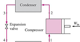
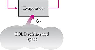
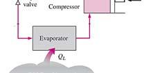
9 11-3 THE IDEAL VAPOR-COMPRESSION REFRIGERATION CYCLE The vapor-compression refrigeration cycle is the ideal model for refrigeration systems. Unlike the reversed Carnot cycle, the refrigerant is vaporized completely l before it is compressed and the turbine is replaced with a throttling device. Schematic and T-s diagram for the ideal vapor-compression refrigeration cycle. This is the most widely used cycle for refrigerators, A-C systems, and heat pumps. The saturated liquid refrigerant at state 3 is throttled to the evaporator pressure by passing it through an expansion valve or capillary tube. The temperature of the refrigerant drops below the temperature of the refrigerated space during this process. The refrigerant enters the evaporator at state 4 as a lowquality saturated mixture, and it completely evaporates by absorbing heat from the refrigerated space. The refrigerant If the throttling device were replaced by an isentropic turbine, the refrigerant would leaves the evaporator as saturated enter the evaporator at state 4 instead of state 4. As a result, the refrigeration vapor and reenters the compressor, capacity would increase (by the area under process curve 4-4 in Fig. 11 3) and the completing the cycle. net work input would decrease (by the amount of work output of the turbine). Replacing the expansion valve by a turbine is not practical, however, since the added 9 benefits cannot justify the added cost and complexity.
10 A schematic diagram showing a typical vapor compression refrigeration cycle. The compressor raises the pressure of the refrigerant, which also increases the temperature. The compressed high-temperature refrigerant vapor then transfers heat to the ambient environment in the condenser, where it condenses to a high-pressure liquid at a temperature close to the environmental temperature. The liquid refrigerant is then passed through the expansion valve where the pressure is suddenly reduced, resulting in a vapor liquid mixture at a much lower temperature. The low temperature refrigerant is then used to cool air or water in the evaporator where the liquid refrigerant evaporates by absorbing heat from the medium being cooled. The cycle is completed by the vapor returning to the compressor. If water is cooled in the evaporator, the device is usually called a chiller. The chilled water could then be used to cool air in a building. 10


 process.")
11 The ideal vapor-compression refrigeration cycle involves an irreversible (throttling) process to make it a more realistic model for the actual systems. Replacing the expansion valve by a turbine is not practical since the added benefits cannot justify the added cost and complexity. Steady-flow energy balance the ideal vapor compression refrigeration cycle is not an internally reversible cycle since it involves an irreversible (throttling) process. An ordinary household refrigerator. fi The P-h diagram of an ideal vaporcompression refrigeration cycle. 11
12 EXAMPLE: A refrigerator uses refrigerant-134a as the working fluid and operates on an ideal vapor-compression refrigeration cycle between 0.12 and 0.7 MPa. The mass flow rate of the refrigerant is 0.05 kg/s. Show the cycle on a T-s diagram with respect to saturation lines. Determine (a) the rate of heat removal from the refrigerated space and the power input to the compressor, (b) the rate of heat rejection to the environment, and (c) the coefficient of performance. 12

13 SOLUTION: 13
14 11-14 ACTUAL VAPOR-COMPRESSION REFRIGERATION CYCLE An actual vapor-compression refrigeration cycle differs from the ideal one in several ways, owing mostly to the irreversibilities that occur in various components, mainly due to fluid friction (causes pressure drops) and heat transfer to or from the surroundings. The COP decreases as a result of irreversibilities. DIFFERENCES Non-isentropic compression Superheated vapor at evaporator exit Subcooled liquid at condenser exit Pressure drops in condenser and evaporator Schematic and T-s diagram for the actual vapor-compression refrigeration cycle. 14
15 In the ideal cycle, the refrigerant leaves the evaporator and enters the compressor as saturated vapor. In practice, however, it may not be possible to control the state of the refrigerant so precisely. Instead, it is easier to design the system so that the refrigerant is slightly superheated at the compressor inlet. This slight overdesign ensures that t the refrigerant is completely l vaporized when it enters the compressor. Also, the line connecting the evaporator to the compressor is usually very long; thus the pressure drop caused by fluid friction and heat transfer from the surroundings to the refrigerant can be very significant. The result of superheating, heat gain in the connecting line, and pressure drops in the evaporator and the connecting line is an increase in the specific volume, thus an increase in the power input requirements to the compressor since steady-flow work is proportional to the specific volume. The compression process in the ideal cycle is internally reversible and adiabatic, and thus isentropic. The actual compression process, however, involves frictional effects, which increase the entropy, and heat transfer, which may increase or decrease the entropy, depending on the direction. Therefore, the entropy of the refrigerant may increase (process 1-2) or decrease (process 1-2 ) during an actual compression process, depending on which effects dominate. The compression process 1-2 may be even more desirable than the isentropic compression process since the specific volume of the refrigerant and thus the work input requirement are smaller in this case. Therefore, the refrigerant should be cooled during the compression process whenever it is practical and economical to do so. In the ideal case, the refrigerant is assumed to leave the condenser as saturated liquid at the compressor exit pressure. In reality, however, it is unavoidable to have some pressure drop in the condenser as well as in the lines connecting the condenser to the compressor and to the throttling valve. Also, it is not easy to execute the condensation process with such precision that the refrigerant is a saturated liquid at the end, and it is undesirable to route the refrigerant to the throttling valve before the refrigerant is completely condensed. Therefore, the refrigerant is subcooled somewhat before it enters the throttling valve. We do not mind this at all, however, since the refrigerant in this case enters the evaporator with a lower enthalpy and thus can absorb b more heat from the refrigerated space. The throttling valve and the evaporator are usually located very close to each other, so the pressure drop in the connecting line is small. 15
16 EXAMPLE: Refrigerant-134a enters the compressor of a refrigerator as superheated vapor at 0.14 MPa and -10 C at a rate of 0.12 kg/s, and it leaves at 0.7 MPa and 50 C. The refrigerant is cooled in the condenser to 24 C and 0.65 MPa, and it is throttled to 0.15 MPa. Disregarding any heat transfer and pressure drops in the connecting lines between the components, show the cycle on a T-s diagram with respect to saturation lines, and determine (a) the rate of heat removal from the refrigerated space and the power input to the compressor, (b) the isentropic efficiency of the compressor, and (c) the COP of the refrigerator. 16

17 SOLUTION 17
18 11-5 SELECTING THE RIGHT REFRIGERANT Several refrigerants may be used in refrigeration systems such as chlorofluorocarbons (CFCs), ammonia, hydrocarbons (propane, ethane, ethylene, etc.), carbon dioxide, air (in the air-conditioning of aircraft), and even water (in applications above the freezing point). R-11, R-12, R-22, R-134a, and R-502 account for over 90 percent of the market. The industrial and heavy-commercial sectors use ammonia (it is toxic). R-11 is used in large-capacity water chillers serving A-C systems in buildings. R-134a (replaced R-12, which damages ozone layer) is used in domestic refrigerators and freezers, as well as automotive air conditioners. R-22 is used in window air conditioners, heat pumps, air conditioners of commercial buildings, and large industrial refrigeration systems, and offers strong competition to ammonia. R-502 (a blend of R-115 and R-22) is the dominant refrigerant used in commercial refrigeration systems such as those in supermarkets. CFCs allow more ultraviolet radiation into the earth s atmosphere by destroying the protective ozone layer and thus contributing to the greenhouse effect that causes global warming. Fully halogenated CFCs (such as R-11, R-12, and R-115) do the most damage to the ozone layer. Refrigerants that are friendly to the ozone layer have been developed. Two important t parameters that t need to be considered d in the selection of a refrigerant are the temperatures of the two media (the refrigerated space and the environment) with which the refrigerant exchanges heat. 18
19 11-6 HEAT PUMP SYSTEMS The most common energy source for heat pumps is atmospheric air (air-to- air systems). Water-source systems usually use well water and ground-source (geothermal) heat pumps use earth as the energy source. They typically have higher COPs but are more complex and more expensive to install. Both the capacity and the efficiency of a heat Evaporator pump fall significantly at low temperatures. Therefore, most air-source heat pumps require a Condenser supplementary heating system such as electric resistance heaters or a gas furnace. Heat pumps are most competitive in areas that Condenser A heat pump can be used to heat a house in winter and to cool it in summer. Evaporator have a large cooling load during the cooling season and a relatively small heating load during the heating season. In these areas, the heat pump can meet the entire cooling and heating needs of residential or commercial buildings. The major problem with air-source systems is frosting, which occurs in humid climates when the temperature falls below 2 to 5 C. Water-source systems usually use well water from depths of up to 80 m in the temperature range of 5 to 18 C, and they do not have a frosting problem. They typically have higher COPs but are more complex and require easy access to a large body of water such as underground water. The condenser of the heat pump (located indoors) functions as the evaporator of the air conditioner in summer. Also, the evaporator of the heat pump (located outdoors) serves as the condenser of the air conditioner. This feature increases the competitiveness of the heat pump. 19

20 EXAMPLE: A heat pump with refrigerant-134a as the working fluid is used to keep a space at 25 C by absorbing heat from geothermal water that enters the evaporator at 50 C at a rate of kg/s and leaves at 40 C. The refrigerant enters the evaporator at 20 C with a quality of 23 percent and leaves at the inlet pressure as saturated vapor. The refrigerant loses 300 W of heat to the surroundings as it flows through the compressor and the refrigerant leaves the compressor at 1.4 Mpa at the same entropy as the inlet. Determine (a) the degrees of subcooling of the refrigerant in the condenser, (b) the mass flow rate of the refrigerant, (c) the heating load and the COP of the heat pump 20
21 SOLUTION More information you need such as compressed region subcooled by 3 C. What do we mean by:the refrigerant enters the compressor at 200 kpa superheated by 4 C asan an example 21
22
23 11-7 INNOVATIVE VAPOR-COMPRESSION REFRIGERATION SYSTEMS The simple vapor-compression refrigeration cycle is the most widely used refrigeration cycle, and it is adequate for most refrigeration applications. The ordinary vapor-compression refrigeration systems are simple, inexpensive, reliable, and practically maintenance-free. However, for large industrial applications efficiency, not simplicity, is the major concern. Also, for some applications the simple vapor-compression refrigeration cycle is inadequate and needs to be modified. For moderately and very low temperature applications some innovative refrigeration systems are used. The following cycles will be discussed: Cascade refrigeration systems Multistage compression refrigeration systems Multipurpose refrigeration systems with a single compressor Liquefaction of gases 23


24 Cascade Refrigeration Systems Some industrial applications require moderately low temperatures, and the temp range they involve may be too large for a single vapor compression refrigeration cycle to be practical. A large temp range also means a large pressure range in the cycle and a poor performance for a reciprocating compressor. One way of dealing with such situations is to perform the refrigeration process in stages, that is, to have two or more refrigeration cycles that operate in series. Such refrigeration cycles are called cascade refrigeration cycles. A two-stage cascade refrigeration system with the same refrigerant in both stages. The compressor work decreases and the amount of heat absorbed from the refrigerated space increases as a result of cascading. Therefore, cascading improves the COP of a refrigeration system Cascading improves the COP of a refrigeration system. Some systems use three or four stages of cascading. In the cascade system shown in the figure, the refrigerants in both cycles are assumed to be the same. This is not necessary, however, since there is no mixing taking place in the heat exchanger. Therefore, refrigerants with more desirable characteristics can be used in each cycle. In this case, there would be a separate saturation dome for each hfluid, and dthe T-s diagram for one of the cycles would be different. Also, in actual cascade refrigeration systems, the two cycles would overlap somewhat since a temperature difference between the two fluids is needed for any heat transfer 24to take place.
25 EXAMPLE: Consider a two-stage cascade refrigeration system operating between ee the pressure limits of 0.8 and 0.14 MPa. Each stage operates on the ideal vapor-compression refrigeration cycle with refrigerant-134a as the working fluid. Heat rejection from the lower cycle to the upper cycle takes place in an adiabatic counterflow heat exchanger where both streams enter at about 0.4 MPa. If the mass flow rate of the refrigerant through the upper cycle is 0.24 kg/s, determine (a) the mass flow rate of the refrigerant through h the lower cycle, (b) the rate of heat removal from the refrigerated space and the power input to the compressor, and (c) the coefficient of performance of this cascade refrigerator. 25
26 SOLUTION 26
27 Multistage Compression Refrigeration Systems When the fluid used throughout the cascade refrigeration system is the same, the heat exchanger between the stages can be replaced by a mixing chamber (called a flash chamber) since it has better heat transfer characteristics. Mixing chamber A two-stage compression refrigeration system with a flash chamber. In this system, the liquid refrigerant expands in the first expansion valve to the flash chamber pressure, which is the same as the compressor interstage pressure. Part of the liquid vaporizes during this process. This saturated vapor (state 3) ismixed with the superheated vapor from the low-pressure compressor (state 2), and the mixture enters the high- pressure compressor at state 9. This is, in essence, a regeneration process. The saturated liquid (state 7) expands through the second expansion valve into the evaporator, where it picks up heat from the refrigerated space. 27
28 EXAMPLE: A two-stage compression refrigeration system operates with refrigerant-134a between the pressure limits of 1 and 0.14 MPa. The refrigerant leaves the condenser as a saturated liquid and is throttled to a flash chamber operating at 0.5 MPa. The refrigerant leaving the low-pressure compressor at 0.5 MPa is also routed to the flash chamber. The vapor in the flash chamber is then compressed to the condenser pressure by the high-pressure compressor, and the liquid is throttled to the evaporator pressure. Assuming the refrigerant leaves the evaporator as saturated vapor and both compressors are isentropic, determine (a) the fraction of the refrigerant that evaporates as it is throttled to the flash chamber, (b) therateof heat removed from the refrigerated space for a mass flow rate of 0.25 kg/s through the condenser, and (c) the coefficient of performance. 28
29 SOLUTION 29
30 30
31 Multipurpose Refrigeration Systems with a Single Compressor Some applications require refrigeration at more than one temperature. A practical and economical approach is to route all the exit streams from the evaporators to a single compressor and let it handle the compression process for the entire system. Each evaporator operating at different temperatures. Schematic and T-s diagram for a refrigerator freezer unit with one compressor. 31
32 Liquefaction of Gases Many important scientific and engineering processes at cryogenic temperatures (below about C) depend on liquefied gases including the separation of oxygen and nitrogen from air, preparation of liquid propellants for rockets, the study of material properties at low temperatures, and the study of superconductivity. The storage (i.e., hydrogen) and transportation of some gases (i.e., natural gas) are done after they are liquefied at very low temperatures. Several innovative cycles are used dfor the liquefaction of gases. Linde-Hampson system for liquefying gases. 32
33 33


34 11-8 GAS REFRIGERATION CYCLES The reversed Brayton cycle (the gas refrigeration cycle) can be used for refrigeration. Simple gas refrigeration cycle. As explained in Sec. 11 2, the Carnot cycle (the standard of comparison for power cycles) and the reversed Carnot cycle (the standard of comparison for refrigeration cycles) are identical, except that the reversed Carnot cycle operates in the reverse direction. This suggests that the power cycles discussed in earlier chapters can be used as refrigeration cycles by simply reversing them. In fact, the vapor- compression refrigeration cycle is essentially a modified Rankine cycle operating in reverse. Another example is the reversed Stirling cycle, which is the cycle on which Stirling refrigerators operate. In this section, we discuss the reversed Brayton cycle, better known as the gas refrigeration cycle. A closed-cycle gas-turbine engine (BRAYTON CYCLE) 34
 but produces a greater amount of refrigeration (triangular area under B1).")


35 The gas refrigeration cycles have lower COPs relative to the vapor- compression refrigeration cycles or the reversed Carnot cycle. The reversed Carnot cycle consumes a fraction of the net work (area 1A3B) but produces a greater amount of refrigeration (triangular area under B1). An open-cycle aircraft cooling system. Despite their relatively low COPs, the gas refrigeration cycles involve simple, lighter components, which make them suitable for aircraft cooling, and they can incorporate regeneration Atmospheric air is compressed by a compressor, cooled by the surrounding air, and expanded in a turbine. The cool air leaving the turbine is then directly routed to the cabin. All the processes described are internally reversible, and the cycle executed is the ideal gas refrigeration cycle. In actual gas refrigeration cycles, the compression and expansion processes deviate from the isentropic ones. The gas refrigeration cycle deviates from the reversed Carnot cycle because the heat transfer processes are not isothermal. 35
36 The regenerative gas cycle is shown in Fig Regenerative cooling is achieved by inserting a counter-flow heat exchanger into the cycle. Without regeneration, the lowest turbine inlet temperature t is T 0, the temperature t of the surroundings or any other cooling medium. With regeneration, the high-pressure gas is further cooled to T 4 before expanding in the turbine. Lowering the turbine inlet temperature automatically lowers the turbine exit temperature, which is the minimum temperature in the cycle. Extremely low temperatures t can be achieved by repeating this process. Extremely low temperatures can be achieved by repeating regeneration process. Gas refrigeration cycle with regeneration. In gas refrigeration cycles, can we replace the turbine by an expansion valve as we did in vapor-compression refrigeration cycles? Why? No; because h = h(t) for ideal gases, and the temperature of air will not drop during a throttling (h 1 = h 2 ) process. 36
37 EXAMPLE: Air enters the compressor (isentropic efficiency of 80%) of gas refrigeration cycle at 12 C and 50 kpa and the turbine (isentropic efficiency of 85%) at 47 C and 250 kpa. The mass flow rate of air through the cycle is 0.08 kg/s. Assuming variable specific heats for air, determine (a) the rate of refrigeration, (b) The net power input, and (c) the coefficient of performance. 37
38 SOLUTION 38
39 39
40 EXAMPLE: A gas refrigeration system using air as the working fluid has a pressure ratio of 4. Air enters the compressor (isentropic efficiency of 75%) at -7 C. The high-pressure air is cooled to 27 C by rejecting heat to the surroundings. It is further cooled to -15 C by regenerative cooling before it enters the turbine (isentropic efficiency of 80%). Using constant specific heats at room temperature, determine (a) the lowest temperaturere that can be obtained by this cycle, (b) the coefficient of performance of the cycle, and (c) The mass flow rate of air for a refrigeration rate of 12 kw. 40
41 SOLUTION 41
42 w net =q h -q l 42


43 11-9 ABSORPTION REFRIGERATION SYSTEMS The highpressure pure NH 3 vapor hot NH 3 +HO 2 solution, which is weak in NH 3 vapor The vapor NH 3 +H 2 O, which is rich in NH 3 Ammonia absorption refrigeration cycle. Liquid NH 3 +H 2 O solution, which is rich in NH 3 Once the pressure of NH 3 is raised by the components in the box (this is the only thing they are set up to do), it is cooled and condensed in the condenser by rejecting heat to the surroundings, is throttled to the evaporator pressure, and absorbs heat from the refrigerated space as it flows through the evaporator. So, there is nothing new there. When there is a source of inexpensive thermal energy at a temperature of 100 to 200 C is absorption refrigeration. Some examples include geothermal energy, solar energy, and waste heat from cogeneration or process steam plants, and even natural gas when it is at a relatively low price. ammonia (NH 3 ) serves as the refrigerant and water (H 2 O) as the transport medium. System looks very much like the vapor-compression system, except that the compressor has been replaced by a complex absorption mechanism consisting of an absorber, a pump, a generator, a regenerator, a valve, and a rectifier. The fluid in the absorber is cooled to maximize i the refrigerant content t of the liquid; the fluid in the generator is heated to maximize the refrigerant content of the vapor. 43
44 Here is what happens in the box: Ammonia vapor leaves the evaporator and enters the absorber, where it dissolves and reacts with water to form NH 3 +H 2 O solution. This is an exothermic reaction; thus heat is released during this process. The amount of NH 3 that can be dissolved in H 2 O is inversely proportional to the temperature. Therefore, it is necessary to cool the absorber to maintain its temperature as low as possible, hence to maximize the amount of NH 3 dissolved in water. The liquid NH 3 +H 2 O solution, which is rich in NH 3, is then pumped to the generator. Heat is transferred to the solution from a source to vaporize some of the solution. The vapor, which is rich in NH 3, passes through a rectifier, which separates the water and returns it to the generator. The high-pressure pure NH 3 vapor then continues its journey through the rest of the cycle. The hot NH 3 + H 2 O solution, which is weak in NH 3, then passes through a regenerator, where it transfers some heat to the rich solution leaving the pump, and is throttled to the absorber pressure. Compared with vapor-compression systems, absorption refrigeration systems have one major advantage: A liquid is compressed instead of a vapor. The steady-flow work is proportional to the specific volume, and thus the work input for absorption refrigeration systems is very small (on the order of one percent of the heat supplied to the generator) and often neglected in the cycle analysis. The operation of these systems is based on heat transfer from an external source. Therefore, absorption refrigeration systems are often classified as heat-driven systems. 44
45 Absorption refrigeration systems (ARS) involve the absorption of a refrigerant by a transport medium. The most widely used system stem is the ammonia water ater system, stem where ammonia (NH 3 ) serves as the refrigerant and water (H 2 O) as the transport medium. Other systems include water lithium bromide and water lithium chloride systems, where water serves as the refrigerant. These systems are limited to applications such as A-C where the minimum temperature is above the freezing point of water. Compared with vapor-compression systems, ARS have one major advantage: A liquid is compressed instead of a vapor and as a result the work input is very small (on the order of one percent of the heat supplied to the generator) and often neglected in the cycle analysis. ARS are often classified as heat-driven systems. ARS are much more expensive than the vapor-compression refrigeration systems. They are more complex and occupy more space, they are much less efficient thus requiring much larger cooling towers to reject the waste heat, and they are more difficult to service since they are less common. Therefore, ARS should be considered only when the unit cost of thermal energy is low and is projected to remain low relative to electricity. i ARS are primarily used in large commercial and industrial installations. 45


46 From Ch 6 Schematic of a heat engine. 46
47 The COP of actual absorption refrigeration systems is usually less than 1. Air-conditioning systems based on absorption refrigeration, called absorption chillers, perform best when the heat source can supply heat at a high temperature with little temperature drop. Determining the maximum COP of an absorption refrigeration system. where T L, T 0, and T s are the thermodynamic temperatures of the refrigerated space, the environment, and the heat source, respectively 47
48 EXAMPLE: Heat is supplied to anabsorption refrigeration fi system from a geothermal well at 130 C at a rate of 5 x 10⁵ kj/h. The environment is at 25 C, and the refrigerated space is maintained i at -30 C. Determine the maximum rate at which h this system can remove heat from the refrigerated space. SOLUTION: 48
49 Summary Refrigerators and Heat Pumps The Reversed Carnot Cycle The Ideal Vapor-Compression Refrigeration Cycle Actual Vapor-Compression Refrigeration Cycle Selecting the Right Refrigerant Heat Pump Systems Innovative Vapor-Compression Refrigeration Systems 49
Chapter 11 REFRIGERATION CYCLES
 Thermodynamics: An Engineering Approach, 6 th Edition Yunus A. Cengel, Michael A. Boles McGraw-Hill, 2008 Chapter 11 REFRIGERATION CYCLES Wan Rosli Wan Sulaiman Copyright The McGraw-Hill Companies, Inc.
Chapter 11 REFRIGERATION CYCLES
 Thermodynamics: An Engineering Approach Seventh Edition in SI Units Yunus A. Cengel, Michael A. Boles McGraw-Hill, 2011 Chapter 11 REFRIGERATION CYCLES Mehmet Kanoglu University of Gaziantep Copyright
Refrigeration Cycles MOHAMMAD FAISAL HAIDER. Bangladesh University of Engineering and Technology
 Refrigeration Cycles MOHAMMAD FAISAL HAIDER LECTURER Department of Mechanical Engineering Department of Mechanical Engineering Bangladesh University of Engineering and Technology Objectives Introduce the
Thermodynamics II Chapter 5 Refrigeration
 Thermodynamics II Chapter 5 Refrigeration Mohsin Mohd Sies Fakulti Kejuruteraan Mekanikal, Universiti Teknologi Malaysia Objectives Introduce the concepts of refrigerators and heat pumps and the measure
Thermodynamics I. Refrigeration and Heat Pump Cycles
 Thermodynamics I Refrigeration and Heat Pump Cycles Dr.-Eng. Zayed Al-Hamamre 1 Content Introduction The Reversed Carnot Cycle The Ideal Compression Refrigeration Systems Deviation from the ICRS Selection
Refrigerants Type Expensive Coefficient of Performance Toxic
 Chapter 11: Refrigeration Cycles 11.5. Selecting the Right Refrigerants When designing a refrigeration system, there are several refrigerants from which to choose, such as chlorofluorocarbons (CFCs), ammonia,
Week 9. Refrigeration Cycles I. GENESYS Laboratory
 Week 9. Refrigeration Cycles I Objectives 1. Introduce the concepts of refrigerators and heat pumps and the measure of their performance. 2. Analyze the ideal vapor-compression refrigeration cycle. 3.
Chapter 10. Refrigeration and Heat Pump Systems
 Chapter 10 Refrigeration and Heat Pump Systems Learning Outcomes Demonstrate understanding of basic vaporcompression refrigeration and heat pump systems. Develop and analyze thermodynamic models of vapor-compression
Chapter 9. Refrigeration and Liquefaction
 Chapter 9 Refrigeration and Liquefaction Refrigeration is best known for its use in the air conditioning of buildings and in the treatment, transportation, and preservation of foods and beverages. It also
Refrigerator and Heat Pump Objectives
 10 CHAPTER Refrigeration Cycles 10-1 Refrigerator and Heat Pump Objectives The objective of a refrigerator is to remove heat (Q L ) from the cold medium; the objective of a heat pump is to supply heat
Chapter 11. Refrigeration Cycles. Study Guide in PowerPoint
 Chapter 11 Refrigeration Cycles Study Guide in PowerPoint to accompany Thermodynamics: An Engineering Approach, 7th edition by Yunus A. Çengel and Michael A. Boles The vapor compression refrigeration cycle
Engineering Thermodynamics. Chapter 7
 Chapter 7 Vapor-Power Cycle 4.1 Introduction Steam power plants are the major sources of power generation. They operate essentially on the principle that steam generated in the boiler passes through steam
Chapter 10 Lyes KADEM [Thermodynamics II] 2007
![Chapter 10 Lyes KADEM [Thermodynamics II] 2007](/thumbs/85/92279486.jpg "Chapter 10 Lyes KADEM [Thermodynamics II] 2007") Refrigeration Cycles The objective of refrigeration cycles is to transfer the heat from a low temperature region to a high temperature region. - if the objective of the cycle is to decrease the lowest
Refrigeration Cycles The objective of refrigeration cycles is to transfer the heat from a low temperature region to a high temperature region. - if the objective of the cycle is to decrease the lowest
Homework Chapter2. Homework Chapter3
 Homework Chapter2 2/1 A storage tank holds methane at 120 K, with a quality of 25 %, and it warms up by 5 C per hour due to a failure in the refrigeration system. How long time will it take before the
Chapter 10 VAPOR AND COMBINED POWER CYCLES
 Thermodynamics: An Engineering Approach Seventh Edition Yunus A. Cengel, Michael A. Boles McGraw-Hill, 2011 Chapter 10 VAPOR AND COMBINED POWER CYCLES Copyright The McGraw-Hill Companies, Inc. Permission
Fig.: macroscopic kinetic energy is an organized form of energy and is much more useful
 Harnessing Energy Fig.: macroscopic kinetic energy is an organized form of energy and is much more useful Vapor Power Cycle The vast majority of electrical generating plants are variations of vapor power
Week 13 Chapter 10 Vapor & Combined Power Cycles
 MECH341: Thermodynamics of Engineering System Week 13 Chapter 10 Vapor & Combined Power Cycles The Carnot vapor cycle The Carnot cycle is the most efficient cycle operating between two specified temperature
we will examine only the vapour compression systems transfers to the Carnot cycle can serve as the initial model of the ideal refrigeration cycle.
 Refrigeration Cycle Reading Problems 10-1 10-5, 10-7, 10-9 10-11, 10-14, 10-39 Definitions a refrigeration system removes thermal energy from a low-temperature region and transfers heat to a high-temperature
Refrigeration and Air Conditioning
 Refrigeration and Air Conditioning 1. Pick up the wrong statement. A refrigerant should have (a) Tow specific heat of liquid (b) high boiling point (c) high latent heat of vaporisation (d) higher critical
Thermodynamics: Homework A Set 7 Jennifer West (2004)
") Thermodynamics: Homework A Set 7 Jennifer West (2004) Problem 1 Water is the working fluid in a Carnot vapor power cycle. Saturated liquid enters the boiler at a pressure of 18 MPa, and saturated vapor
Thermodynamics: Homework A Set 7 Jennifer West (2004) Problem 1 Water is the working fluid in a Carnot vapor power cycle. Saturated liquid enters the boiler at a pressure of 18 MPa, and saturated vapor
Chapter 8. Production of Power from Heat
 Chapter 8 Production of Power from Heat 8.1 THE STEAM POWER PLANT The Carnot-engine cycle, described in Sec. 5.2, operates reversibly and consists of two isothermal steps connected by two adiabatic steps.
(Refer Slide Time: 00:00:40 min)
") Refrigeration and Air Conditioning Prof. M. Ramgopal Department of Mechanical Engineering Indian Institute of Technology, Kharagpur Lecture No. # 10 Vapour Compression Refrigeration Systems (Refer Slide
Refrigeration and Air Conditioning Prof. M. Ramgopal Department of Mechanical Engineering Indian Institute of Technology, Kharagpur Lecture No. # 10 Vapour Compression Refrigeration Systems (Refer Slide
CH2351 Chemical Engineering Thermodynamics II Unit V Refrigeration. Dr. M. Subramanian
 CH2351 Chemical Engineering Thermodynamics II Unit V www.msubbu.in Refrigeration www.msubbu.in Dr. M. Subramanian Associate Professor Department of Chemical Engineering Sri Sivasubramaniya Nadar College
PRESSURE-ENTHALPY CHARTS AND THEIR USE By: Dr. Ralph C. Downing E.I. du Pont de Nemours & Co., Inc. Freon Products Division
 INTRODUCTION PRESSURE-ENTHALPY CHARTS AND THEIR USE The refrigerant in a refrigeration system, regardless of type, is present in two different states. It is present as liquid and as vapor (or gas). During
Paper No. : 04 Paper Title : Unit Operations in Food processing Module 11 : Principles of Refrigeration
 Paper No. : 04 Paper Title : Unit Operations in Food processing Module 11 : Principles of Refrigeration 11.1 Introduction Preservation of foods is a vital processing step in food processing. There are
S.A. Klein and G.F. Nellis Cambridge University Press, 2011
 12.A-1 A mixture of helium and water vapor is flowing through a pipe at T= 90 C and P = 150 kpa. The mole fraction of helium is y He = 0.80. a.) What is the relative humidity of the mixture? b.) What is
RAC. Unit 1. Previous year Questions
 RAC Unit 1 Previous year Questions 1.What is the basic difference between open and closed Air refrigeration cycles? Describe a Bellcoleman or Reversed Joule air refrigeration cycle with the help of a neat
R07. Answer any FIVE Questions All Questions carry equal marks *****
 Set No: 1 III B.Tech. II Semester Supplementary Examinations, April/May 2013 REFRIGERATION AND AIR CONDITIONING (Mechanical Engineering) Time: 3 Hours Max Marks: 80 Answer any FIVE Questions All Questions
3. (a) Explain the working of a rotary screw compressor. [10] (b) How the capacity control is achieved in refrigerant compressor?
![3. (a) Explain the working of a rotary screw compressor. [10] (b) How the capacity control is achieved in refrigerant compressor?](/thumbs/86/93619521.jpg "3. (a) Explain the working of a rotary screw compressor. [10] (b) How the capacity control is achieved in refrigerant compressor?") Code No: RR410305 Set No. 1 IV B.Tech I Semester Regular Examinations, November 2006 REFRIGERATION & AIR CONDITIONING (Mechanical Engineering) Time: 3 hours Max Marks: 80 Answer any FIVE Questions All
Code No: RR410305 Set No. 1 IV B.Tech I Semester Regular Examinations, November 2006 REFRIGERATION & AIR CONDITIONING (Mechanical Engineering) Time: 3 hours Max Marks: 80 Answer any FIVE Questions All
SIDDHARTH GROUP OF INSTITUTIONS :: PUTTUR Siddharth Nagar, Narayanavanam Road AUTONOMOUS QUESTION BANK (DESCRIPTIVE) UNIT I
 UNIT I") SIDDHARTH GROUP OF INSTITUTIONS :: PUTTUR Siddharth Nagar, Narayanavanam Road 517583 AUTONOMOUS QUESTION BANK (DESCRIPTIVE) Subject with Code : Refrigeration and Air Conditioning (16ME8806) Course & Branch:
SIDDHARTH GROUP OF INSTITUTIONS :: PUTTUR Siddharth Nagar, Narayanavanam Road 517583 AUTONOMOUS QUESTION BANK (DESCRIPTIVE) Subject with Code : Refrigeration and Air Conditioning (16ME8806) Course & Branch:
INSTITUTE OF AERONAUTICAL ENGINEERING
 1 P a g e INSTITUTE OF AERONAUTICAL ENGINEERING (Autonomous) Dundigal, Hyderabad -00 043 MECHANICAL ENGINEERING QUESTION BANK Name : REFRIGERATION AND AIR CONDITIONING Code : A60334 Class : III B. Tech
Thermodynamic Calculations of Two-Stage Vapor Compression Refrigeration Cycle with Flash Chamber and Separate Vapor Mixing Intercooler
 Thermodynamic Calculations of Two-Stage Vapor Compression Refrigeration Cycle with Flash Chamber and Separate Vapor Mixing Intercooler Author: Volodymyr Voloshchuk Vl.volodya@gmail.com Introduction In
AND AIR-CONDITIONING. Dr Ali Jawarneh Department of Mechanical Engineering Hashemite University
 Chapter 14 GAS VAPOR MIXTURES AND AIR-CONDITIONING Dr Ali Jawarneh Department of Mechanical Engineering Hashemite University 2 Objectives Differentiate between dry air and atmospheric air. Define and calculate
Dhulapally, Secunderabad Subject: REFRIGERATION AND AIR CONDITIONING QUESTION BANK
 St.MARTIN S ENGINEERING COLLEGE Dhulapally, Secunderabad-500 014 Subject: REFRIGERATION AND AIR CONDITIONING Class : ECE III 1 Define Unit of refrigeration. 2 Define C.O.P. QUESTION BANK 3 What is the
CHAPTER 7 PERFORMANCE ANALYSIS OF VAPOUR COMPRESSION REFRIGERATION SYSTEM IN HYBRID REFRIGERATION SYSTEM
 111 CHAPTER 7 PERFORMANCE ANALYSIS OF VAPOUR COMPRESSION REFRIGERATION SYSTEM IN HYBRID REFRIGERATION SYSTEM 7.1 INTRODUCTION Energy is the primary component to run any system in the world. According to
OPEN SOURCE Project OASIS MACHINE December 27, 2011 Subject ENERGY & WATER PRODUCTION Page 1 of 7 OASIS MACHINE
 Subject ENERGY & WATER PRODUCTION Page 1 of 7 OASIS MACHINE The following 1 st concept sketch was produced as a means of defining this device as we prepare for funding applications. Also to communicate
REFRIGERATION AND AIR CONDITIONING
 REFRIGERATION AND AIR CONDITIONING SECOND EDITION S.N. Sapali Professor of Mechanical Engineering College of Engineering, Pune Delhi-110092 2014 REFRIGERATION AND AIR CONDITIONING, Second Edition S.N.
R10. IV B.Tech I Semester Regular/Supplementary Examinations, Nov/Dec REFRIGERATION & AIR-CONDITIONING (Mechanical Engineering)
") Set No. 1 IV B.Tech I Semester Regular/Supplementary Examinations, Nov/Dec - 2014 REFRIGERATION & AIR-CONDITIONING (Mechanical Engineering) Time: 3 hours Max. Marks: 75 Answer any FIVE Questions All Questions
Set No. 1 IV B.Tech I Semester Regular/Supplementary Examinations, Nov/Dec - 2014 REFRIGERATION & AIR-CONDITIONING (Mechanical Engineering) Time: 3 hours Max. Marks: 75 Answer any FIVE Questions All Questions
ENSC 388. Assignment #6
 ENSC 388 Assignment #6 Assignment date: Wednesday Oct. 21, 2009 Due date: Wednesday Oct. 28, 2009 Problem 1 A turbine operating at steady state receives air at a pressure of 3.0 and a temperature of 390.
PLEASE READ AND FOLLOW THESE INSTRUCTIONS
 ME 300 Final Examination May 2, 2005 161 ME or 261 ME Name: Thermo No. Section: (Please circle) 8:30 a.m. 11:30 a.m. 2:30 p.m. PLEASE READ AND FOLLOW THESE INSTRUCTIONS 1. Put your name on each page of
WORK STUDY ON LOW TEMPERATURE (CASCADE) REFRIGERATION SYSTEM
 REFRIGERATION SYSTEM") WORK STUDY ON LOW TEMPERATURE (CASCADE) REFRIGERATION SYSTEM Sachin Kumar 1, Vicky Ranga 2 1Assistant Professor, Department of Mechanical Engineering, Jagan Nath University Jhajjar, Haryana, India. 2Scholar.
WORK STUDY ON LOW TEMPERATURE (CASCADE) REFRIGERATION SYSTEM Sachin Kumar 1, Vicky Ranga 2 1Assistant Professor, Department of Mechanical Engineering, Jagan Nath University Jhajjar, Haryana, India. 2Scholar.
FS 231: Final Exam (5-6-05) Part A (Closed Book): 60 points
 Part A (Closed Book): 60 points") Name: Start time: End time: FS 231: Final Exam (5-6-05) Part A (Closed Book): 60 points 1. What are the units of the following quantities? (10 points) a. Enthalpy of a refrigerant b. Dryness fraction of
Name: Start time: End time: FS 231: Final Exam (5-6-05) Part A (Closed Book): 60 points 1. What are the units of the following quantities? (10 points) a. Enthalpy of a refrigerant b. Dryness fraction of
S.A. Klein and G.F. Nellis Cambridge University Press, 2011 = 90 F. compressor. condenser. 5 evaporator 1. evap
 9.A-1 Dedicated subcooling is a novel modification for frozen food refrigeration in supermarkets. With the dedicated subcooling modification, liquid refrigerant leaving the condenser is further cooled
Main Anthropogenic Sources of Greenhouse Gases Refrigerants
 Main Anthropogenic Sources of Greenhouse Gases Refrigerants Content Refrigerant definition Refrigerants Refrigerants as a source of GHG Refrigerant Definition A refrigerant is a substance or mixture, usually
Refrigeration Systems
 Refrigeration Systems COP COP = coefficient of performance Air conditioners, refrigerators: COP=QL/Wnet Heat pumps: COP=QH/Wnet Energy balance: Wnet+QL=QH From Cengel, Thermodynamics: An Engineering Approach,
Subscripts 1-4 States of the given system Comp Compressor Cond Condenser E Evaporator vol Volumetric G Gas L Liquid
 Simulation Analysis of Compression Refrigeration Cycle with Different Refrigerants P.Thangavel, Dr.P.Somasundaram, T.Sivakumar, C.Selva Kumar, G.Vetriselvan Abstract --- In this analysis, the performance
Homework #4 (group) Tuesday, 27 by 4:00 pm 5290 exercises (individual) Tuesday, 27 by 4:00 pm extra credit (individual) Tuesday, 27 by 4:00 pm
 Tuesday, 27 by 4:00 pm 5290 exercises (individual) Tuesday, 27 by 4:00 pm extra credit (individual) Tuesday, 27 by 4:00 pm") Homework #4 (group) Tuesday, 27 by 4:00 pm 5290 exercises (individual) Tuesday, 27 by 4:00 pm extra credit (individual) Tuesday, 27 by 4:00 pm Readings for this homework assignment and upcoming lectures
Homework #4 (group) Tuesday, 27 by 4:00 pm 5290 exercises (individual) Tuesday, 27 by 4:00 pm extra credit (individual) Tuesday, 27 by 4:00 pm Readings for this homework assignment and upcoming lectures
Basically 1 TR would mean the amt of heat removed = 211KJ/min from storage space.
 #1 Refrigeration is the process of MAINTAINING a lower temperature as compared to the surroundings. Be it continuous generation of work from heat or maintaining a lower temp, we have to conduct these operations
c Dr. Md. Zahurul Haq (BUET) Refrigeration Cycles ME 6101 (2013) 2 / 25 T270 COP R = Q L
 Refrigeration Cycles ME 6101 (2013) 2 / 25 T270 COP R = Q L") Refrigeration Cycles Dr. Md. Zahurul Haq Professor Department of Mechanical Engineering Bangladesh University of Engineering & Technology (BUET) Dhaka-1000, Bangladesh zahurul@me.buet.ac.bd http://teacher.buet.ac.bd/zahurul/
Refrigeration Cycles Dr. Md. Zahurul Haq Professor Department of Mechanical Engineering Bangladesh University of Engineering & Technology (BUET) Dhaka-1000, Bangladesh zahurul@me.buet.ac.bd http://teacher.buet.ac.bd/zahurul/
pdfmachine trial version
 HVAC PROBLEM SHEET # 02(REVERSED BRAYTON CYCLE) 1. 500 kg of atmospheric air is circulated per hour in an open type of refrigeration installation. The air is drawn from the cold chamber at temperature
Refrigeration Cycles. Refrigerators, Air-conditioners & Heat Pumps. Refrigeration Capacity/Performance. Dr. Md. Zahurul Haq
 Refrigeration Cycles Dr. Md. Zahurul Haq Professor Department of Mechanical Engineering Bangladesh University of Engineering & Technology (BUET) Dhaka-1000, Bangladesh zahurul@me.buet.ac.bd http://teacher.buet.ac.bd/zahurul/
SHRI RAMSWAROOP MEMORIAL COLLEGE OF ENGG. & MANAGEMENT
 QUIZ TEST-1 Time: 1 Hour REFREGERATION AND AIRCONDITIONING Max. Marks: 30 Q1) A refrigerator working on Bell-Coleman cycle (Reverse Brayton cycle) operates between 1 bar and 10 bar. Air is drawn from cold
Steam Power Cycles Part II
 Steam Power Cycles Part II Regenerative Cycles - Open and Closed Feedwater Heaters One approach to increasing the efficiency of steam power cycle is by extracting some of the steam from various stages
T270 COP R = Q L. c Dr. Md. Zahurul Haq (BUET) Refrigeration Cycles ME 6101 (2017) 2 / 23 T354
 Refrigeration Cycles ME 6101 (2017) 2 / 23 T354") Refrigerators, Air-conditioners & Heat Pumps Refrigeration Cycles Dr. Md. Zahurul Haq Professor Department of Mechanical Engineering Bangladesh University of Engineering & Technology (BUET) Dhaka-1000,
Refrigerators, Air-conditioners & Heat Pumps Refrigeration Cycles Dr. Md. Zahurul Haq Professor Department of Mechanical Engineering Bangladesh University of Engineering & Technology (BUET) Dhaka-1000,
Institute of Aeronautical Engineering (Autonomous) Dundigal, Hyderabad B.Tech (III II SEM) MECHANICAL ENGINEERING
 Dundigal, Hyderabad B.Tech (III II SEM) MECHANICAL ENGINEERING") Institute of Aeronautical Engineering (Autonomous) Dundigal, Hyderabad- 500 043 B.Tech (III II SEM) MECHANICAL ENGINEERING REFRIGERATION AND AIR CONDITIONING Prepared by, Dr. CH V K N S N Moorthy, Professor
Institute of Aeronautical Engineering (Autonomous) Dundigal, Hyderabad- 500 043 B.Tech (III II SEM) MECHANICAL ENGINEERING REFRIGERATION AND AIR CONDITIONING Prepared by, Dr. CH V K N S N Moorthy, Professor
SAMPLE STUDY MATERIAL
 R.A.C.-ME GAE, IES, PSU SAMPLE SUDY MAERIAL Mechanical Engineering ME Postal Correspondence Course Refrigeration & Air Conditioning GAE, IES & PSUs R.A.C.-ME GAE, IES, PSU 2 C O N E N. INRODUCION & BASIC
Section 1: Theory of Heat Unit 3: Refrigeration and Refrigerants
 Section 1: Theory of Heat Unit 3: Refrigeration and Refrigerants Unit Objectives After studying this chapter, you should be able to: Discuss applications for high-, medium-, and low temperature refrigeration.
ISSN Vol.08,Issue.21, November-2016, Pages:
 ISSN 2348 2370 Vol.08,Issue.21, November-2016, Pages:4164-4170 www.ijatir.org Thermal Analysis of Vapour Compression Cycle for Different Refrigerants ALI MOHAMMED ABDOULHA MASSOUD 1, DR. MOHAMMAD TARIQ
CHAPTER 1 INTRODUCTION
 1 CHAPTER 1 INTRODUCTION 1.1 Background The science which deals with creating a controlled climate in indoor space is called air conditioning. Earlier days the air-conditioning was treated as a luxury,
Role of Nano-technology for improving of thermal performances of vapour compression refrigeration system (VCRS): An Overview
: An Overview") International Journal of Research in Engineering and Innovation Vol-2, Issue-1 (2018), 21-28 International Journal of Research in Engineering and Innovation (IJREI) journal home page: http://www.ijrei.com
International Journal of Research in Engineering and Innovation Vol-2, Issue-1 (2018), 21-28 International Journal of Research in Engineering and Innovation (IJREI) journal home page: http://www.ijrei.com
s. Properties for R134a are as follows : Saturated R-134a Superheated R-134a
 CHAPTER 9 REFRIGERATION & AIR-CONDITIONING YEAR 2012 ONE MARK Common Data For Q. 1 and Q.2 A refrigerator operates between 120 kpa and 800 kpa in an ideal vapour compression cycle with R-134a as the refrigerant.
Solution of I Mid Term Steam Engineering 6ME5A
 1(a) Discuss the working principle of LaMont high pressure boiler This boiler works on basic principle of forced convection. If the water is circulate by a pump inside the tube, the heat transfer rate
REFRIGERATION CYCLE Principles of Mechanical Refrigeration Level 2: Cycle Analysis
 REFRIGERATION CYCLE Principles of Mechanical Refrigeration Level 2: Cycle Analysis Technical Development Program Technical Development Programs (TDP) are modules of technical training on HVAC theory, system
Air Conditioning Clinic. Absorption Water Chillers One of the Equipment Series TRG-TRC011-EN
 Air Conditioning Clinic Absorption Water Chillers One of the Equipment Series TRG-TRC011-EN Absorption Water Chillers One of the Equipment Series A publication of The Trane Company Worldwide Applied Systems
SSC-JE STAFF SELECTION COMMISSION MECHANICAL ENGINEERING STUDY MATERIAL REFRIGERATION CYCLES REFRIGERATION CYCLES REFRIGERATION CYCLES
 SSC-JE SAFF SELECION COMMISSION MECHANICAL ENGINEERING SUDY MAERIAL 2 Syllabus: hermal Engineering () Refrigeration cycles; Principle of a Refrigeration Subject wise paper analysis: Mechanical Engineering
Purpose of Refrigeration
 Refrigeration Outline Purpose of refrigeration Examples and applications Choice of coolant and refrigerants Phase diagram of water and CO 2 Vapor compression refrigeration system Pressure-enthalpy diagram
HVAC Fundamentals & Refrigeration Cycle
 HVAC Fundamentals & Refrigeration Cycle Change of State of Water & the Refrigeration Cycle Change of State Water The Basic Refrigeration Cycle Types of DX Systems The Chilled water System The Cooling Tower
Nova Movie: Absolute Zero
 Nova Movie: Absolute Zero On a scale of 1 to 5 (1 being the best), how do you rank the Nova movie Absolute Zero compared to all other Nova presentations you have watched? A. 1 B. 2 C. 3 D. 4 E. 5 Gas Expansion
UNIT-1 Q.1 Draw P-V and T-s diagram of Reversed Carnot cycle (2M-Apr./May-2009) Q.2 Define Ton of refrigeration and COP. (2M- Nov/Dec-2009)
 Q.2 Define Ton of refrigeration and COP. (2M- Nov/Dec-2009)") UNIT-1 Q.1 Draw P-V and T-s diagram of Reversed Carnot cycle (2M-Apr./May-2009) Q.2 Define Ton of refrigeration and COP. (2M- Nov/Dec-2009) (2M-Apr./May-2011) Q.3 Differentiate between heat engine and
UNIT-1 Q.1 Draw P-V and T-s diagram of Reversed Carnot cycle (2M-Apr./May-2009) Q.2 Define Ton of refrigeration and COP. (2M- Nov/Dec-2009) (2M-Apr./May-2011) Q.3 Differentiate between heat engine and
Design and development of vapor absorption refrigeration system for rural dwellers. Adekeye, T. Oyedepo, S.O and Oyebanji, J.A
 Design and development of vapor absorption refrigeration system for rural dwellers Abstract Adekeye, T. Oyedepo, S.O and Oyebanji, J.A Mechanical Engineering Department, Covenant University, Ota Nigeria
A Comparison Between Refrigerants Used In Air Conditioning
 A Comparison Between Refrigerants Used In Air Conditioning Derya Özkan, Özden Agra and Özlem Çetin University of Yildiz Technical University, Turkey Corresponding email: tumer@yildiz.edu.tr SUMMARY It
Applications of Thermodynamics: Heat Pumps and Refrigerators
 Applications of Thermodynamics: Heat Pumps and Refrigerators Bởi: OpenStaxCollege Almost every home contains a refrigerator. Most people don t realize they are also sharing their homes with a heat pump.
ME 410 MECHANICAL ENGINEERING SYSTEMS LABORATORY MASS & ENERGY BALANCES IN PSYCHROMETRIC PROCESSES EXPERIMENT 3
 ME 410 MECHANICAL ENGINEERING SYSTEMS LABORATORY MASS & ENERGY BALANCES IN PSYCHROMETRIC PROCESSES EXPERIMENT 3 1. OBJECTIVE The objective of this experiment is to observe four basic psychrometric processes
UNIT - 3 Refrigeration and Air - Conditioning
 UNIT - 3 Refrigeration and Air - Conditioning Science of providing and maintaining temperatures below that of surroundings I n t r o d u c t i o n t o R e f r i g e r a t i o n The term refrigeration may
1 /35 2 /35 3 /30 Total /100
 Test is open book and notes. Answer all questions and sign honor code statement: I have neither given nor received unauthorized assistance during this exam. Signed Remember to show your work partial credit
Natural refrigerants - naturally efficient
 Natural refrigerants - naturally efficient Operating systems with natural refrigerants for energy efficiency Frankfurt (Main), 10/11/2016. Whether energy transition in Germany or Energy Efficiency Act
Case 15 Refrigeration System for Chemical Fertilizer Plant Ammonia Storage
 Case 15 Refrigeration System for Chemical Fertilizer Plant Ammonia Storage Copy Right By: Thomas T.S. Wan ) Dec. 28, 2012 All Rights Reserved Case Background: Ammonia is one of the important elements to
Compendium DES July 2016, CARN
 Compendium DES July 2016, CARN 1 Contents Contents... 2 1. Energy balance... 4 Using Energy Balance for analyzing energy systems... 4 Energy Balance definition... 4 Steady state, steady flow... 4 Methodology...
: REFRIGERATION & AIR CONDITIONING COURSE CODE : 6023 COURSE CATEGORY : A PERIODS/ WEEK : 6 PERIODS/ SEMESTER : 90 CREDIT : 6 TIME SCHEDULE
 COURSE TITLE : REFRIGERATION & AIR CONDITIONING COURSE CODE : 6023 COURSE CATEGORY : A PERIODS/ WEEK : 6 PERIODS/ SEMESTER : 90 CREDIT : 6 TIME SCHEDULE MODULE TOPIC PERIODS 1 Introduction. Applications
 MECHANICAL DEPARTMENT, OITM SEM: 6 TH REFRIGERATION & AIR-CONDITIONING PAPER: ME-302-E UNIT-I Q.1 (a) Derive an expression for the COP of Bell-Coleman refrigeration cycle in terms of pressure. (10) [May-09]
MECHANICAL ENGINEERING ME.2017 FUNDAMENTAL OF REFRIGERATION AND AIR CONDITIONING. Sample Questions and Answers
 MECHANICAL ENGINEERING ME.2017 FUNDAMENTAL OF REFRIGERATION AND AIR CONDITIONING Sample Questions and Answers CHAPTER 5 EVAPORATORS 1. What is Evaporator? Classify the various types of evaporator. Evaporator
Vapour Compression-Absorption Cascade Refrigeration System- Thermodynamic Analysis
 Vapour Compression-Absorption Cascade Refrigeration System- Thermodynamic Analysis PARBHUBHAI R.TAILOR Department of Mechanical Engineering Sardar Vallabhbhai National Institute of Technology Surat,Gujarat-395007,INDIA
Q. Which hydrocarbons can be used as a refrigerant? The following hydrocarbons can be used as a refrigerant in cooling & heating applications:
 Basic Facts About Hydrocarbons Q. What are hydrocarbons? Hydrocarbon refrigerants are environmentally friendly, non-toxic, non-ozone-depleting replacement for chlorofluorocarbons (CFCs), hydrochlorofluorocarbons
Modelling the Performance of a Diffusion Absorption Refrigeration System
 Modelling the Performance of a Diffusion Absorption Refrigeration System Noman Yousuf 1, Etienne Biteau 2, Timothy Anderson 1, Michael Gschwendtner 1 and Roy Nates 1 1 School of Engineering, Auckland University
REFRIGERATION AND AIR CONDITIONING
 REFRIGERATION AND AIR CONDITIONING About the Author Late (Dr.) Ramesh Chandra Arora served as Professor of Mechanical Engineering at Indian Institute of Technology Kharagpur from 1987 to 2005. He received
SIR C.R.REDDY COLLEGE OF ENGINEERING, ELURU DEPARTMENT OF MECHANICAL ENGINEERING ETD-II. Model Short Answer Questions And Answers
 SIR C.R.REDDY COLLEGE OF ENGINEERING, ELURU DEPARTMENT OF MECHANICAL ENGINEERING ETD-II Model Short Answer Questions And Answers VAPOUR POWER CYCLES 1. What are the methods to increase thermal efficiency
(ME-225) HEATING, VENTILATION AND AIR-CONDITIONING SYSTEM
 HEATING, VENTILATION AND AIR-CONDITIONING SYSTEM") (ME-225) HEATING, VENTILATION AND AIR-CONDITIONING SYSTEM MUHAMMAD UMER SOHAIL PhD, AEROSPACE SCHOLOR (INSTITUTE OF SPACE TECHNOLOGY) MS POWER MECHANICAL (MUST) MBA (COL) EXECUTIVE (SAARC AIOU) BSC MECHANICAL
(ME-225) HEATING, VENTILATION AND AIR-CONDITIONING SYSTEM MUHAMMAD UMER SOHAIL PhD, AEROSPACE SCHOLOR (INSTITUTE OF SPACE TECHNOLOGY) MS POWER MECHANICAL (MUST) MBA (COL) EXECUTIVE (SAARC AIOU) BSC MECHANICAL
4.1 Refrigeration process comparison
 Refrigeration (Kylteknik) course # 424519.0 v. 2017 4. Refrigeration process comparison; process equipment Ron Zevenhoven Åbo Akademi University Thermal and Flow Engineering Laboratory / Värme- och strömningsteknik
Natural gas liquefaction cycles
 Natural gas liquefaction cycles Constantinos Hadjistassou, PhD Assistant Professor Programme in Oil & Gas (Energy) Engineering University of Nicosia Web: www.carbonlab.eu Nov., 2015 Overview Liquefaction
Performance Analysis of Li-Br Water Refrigeration System with Double Coil Anti-Swirl Shell and Coil Heat Exchangers
 e-issn 2455 1392 Volume 2 Issue 5, May 2016 pp. 108-116 Scientific Journal Impact Factor : 3.468 http://www.ijcter.com Performance Analysis of Li-Br Water Refrigeration System with Double Coil Anti-Swirl
LPG Refrigerator. October 2017 IJIRT Volume 4 Issue 5 ISSN:
 LPG Refrigerator Midde.Surendra Goud 1, Thota.Ayyappa 2 Mother Teresa Institute of Science and Technology, Sathupally Abstract-This study investigates the result of an experimental study carried out to
CHAPTER 1 INTRODUCTION
 CHAPTER 1 INTRODUCTION 1.1 CFC REFRIGERANTS Since the 1930s, chlorofluorocarbons (CFCs) have been widely used as foam blowing agents, aerosols and especially refrigerants due to their pre-eminent properties
Modeling And Testing Of R23/R134a Mixed Refrigerant System With Water Cooled Separator For Low Temperature Refrigeration
 Marquette University e-publications@marquette Master's Theses (2009 -) Dissertations, Theses, and Professional Projects Modeling And Testing Of R23/R134a Mixed Refrigerant System With Water Cooled Separator
Low-Power Air Conditioning Technology with Cold Thermal Energy Storage
 Sustainable Energy, 2014, Vol. 2, No. 3, 116-120 Available online at http://pubs.sciepub.com/rse/2/3/6 Science and Education Publishing DOI:10.12691/rse-2-3-6 Low-Power Air Conditioning Technology with
REFRIGERATION CYCLES
 REFRIGERATION CYCLES Carnot Cycle We start discussing the well-known Carnot cycle in its refrigeration mode. Figure 1: Carnot Cycle In this cycle we define the coefficient of performance as follows: COP
LECTURE-18 Vapour Absorption Refrigeration System
 Lecturer: -Dr. Esam Mejbil Abid Subject: Air Conditioning and Refrigeration Year: Fourth B.Sc. Babylon University College of Engineering Department of Mechanical Engineering LECTURE-18 Vapour Absorption
International Journal of Research in Engineering and Innovation Vol-1, Issue-5 (2017), 68-72
, 68-72") International Journal of Research in Engineering and Innovation Vol-1, Issue-5 (2017), 68-72 International Journal of Research in Engineering and Innovation (IJREI) journal home page: http://www.ijrei.com
International Journal of Research in Engineering and Innovation Vol-1, Issue-5 (2017), 68-72 International Journal of Research in Engineering and Innovation (IJREI) journal home page: http://www.ijrei.com
Vapour Compression Refrigeration Systems
 Vapour Compression Refrigeration Systems Nagendra M CBM Engineer, Hindusthan Zink.Ltd The specific objectives of the lesson: This lesson examines the most usually utilized refrigeration system, i.e. Vapour
Chapter-8 Capacity Control of Refrigeration Systems
 Chapter-8 Capacity Control of Refrigeration Systems Chapter-8 Capacity Control of Refrigeration Systems ၈.၁ Compressor Control Chiller Control and Chilled Water Plant Control Refrigeration system control
Refrigeration Systems and Accessories
 As with the Chapter Review Tests and the Final Exam, the tests your understanding of the materials underlying the learning objectives. After you ve reviewed your answers to the Chapter Review Tests, try