BUILD IN APPLIANCES FOR USE WITH LIQUIFIED PETROLEUM GAS
|
|
|
- Blaze McCarthy
- 6 years ago
- Views:
Transcription

1 BUILD IN APPLIANCES FOR USE WITH LIQUIFIED PETROLEUM GAS MODELS S~OH70000 S~OH76000 (LPG) S~OH71000 S~OH77000 (DUAL FUEL) USER AND INSTALLATION INSTRUCTIONS PCC 1265 Issue 10 - GB WARNING Read the instructions before use Only use appliance in a well ventilated area Install the appliance in accordance with the regulations in force For use in GB NL DE FR ES PT IT SE NO DK SI SK THETFORD LIMITED UNIT 19 Oakham Drive, Parkwood Industrial Estate Rutland Road, Sheffield S3 9QY, ENGLAND. TEL: + 44 (0) FAX: + 44 (0)
2 WARNINGS Appliance and accessible parts become hot during use. Avoid touching heating elements. Children less than 8 years of age shall be kept away unless continuously supervised. This appliance can be used by children aged from 8 years and above, persons with reduced physical, sensory or mental capabilities and/or lack of experience and knowledge only if they have been given supervision or instruction concerning use of the appliance in a safe way and understand the hazards involved. Children shall not play with the appliance. Cleaning and user maintenance shall not be made by children without supervision. Unattended cooking on a hob with fat or oil can be dangerous and may result in fire. Never extinguish a fire with water, switch off the appliance and cover flame with lid or fire blanket. Danger of Fire: Do not store items on the cooking surface. Do not use harsh abrasive cleaners or sharp metal scrapers to clean the oven door glass since they can scratch the surface, which may result in shattering of the glass. Never use a steam cleaner to clean appliance. 2

3 TRIPLEX S~OH70000 and S~OH71000 TRIPLEX COOKER RANGE TRIPLEX WIDE S~OH76000 and S~OH77000 W = 445mm / -0.0 W = 496mm / -0.0 #1 = Side battons (optional) 15x40x330 #1 = Side battons (optional) 15x40x330 #2 = Worktop Cutout 493mm #2 = Worktop Cutout 493mm 3


4 MINIMUM DISTANCE TO COMBUSTIBLE MATERIAL Recommended minimum dimensions to combustible material Installers should verify with furniture manufacturer suitability of materials T 10mm X 200mm V 400mm Y & Z 500mm WIRING DIAGRAM 1 GREEN & YELLOW 2 BLUE 3 BROWN 4 BLACK 5 RED 6 YELLOW 7 PURPLE 8 WHITE #1 CABLE CLAMP #2 ROTARY SWITCH #3 WARNING LAMP #4 HOTPLATE EARTH- FASCIA EARTH-BURNER HOTPLATE #5 #6 #7 SUPPORT BRACKET SUPPORT FRAME CONNECTIONS 4
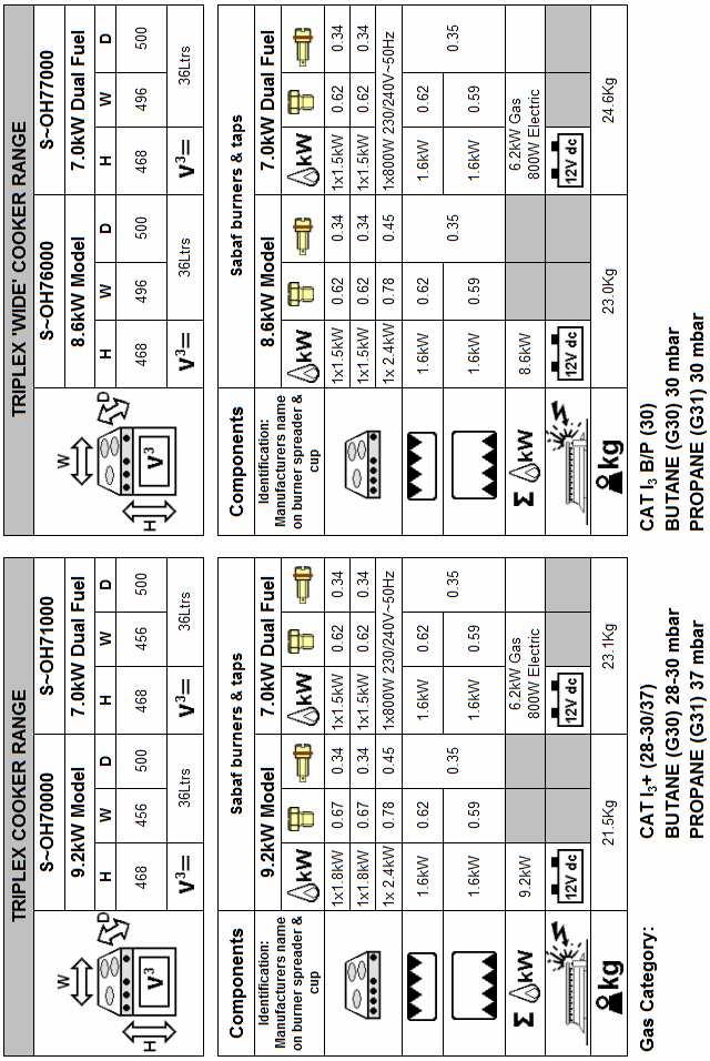
5 SPECIFICATION 5
6 INTRODUCTION This appliance must be installed in accordance with the local, national and European regulations in force. Particular attention shall be given to the requirements regarding ventilation. Read the instructions before installing or using the appliance The appliance is designed for either high or low level installations. Failure to install the appliance correctly could invalidate any warranty or liability claims and lead to prosecution. Please refer to the methods of installation within this handbook. Our policy is one of continuous development and improvement. Specifications and illustrations may change subsequent to publication. Provision Of Ventilation The use of a gas cooking appliance results in the production of heat and moisture in a room in which it is installed. Ensure that the kitchen is well ventilated, keep natural ventilation holes open or install a mechanical ventilation device (mechanical extractor hood). Prolonged intensive use of the appliance may call for additional ventilation, for example opening a window, or more effective ventilation, for example increasing the level of mechanical ventilation where present. The room containing the appliance should have an air supply in accordance with local, national and European standards. Position This appliance must be positioned free from draughts, which may affect the combustion and in a manner that will prevent the accumulation of unburnt gas. When in use ensure that air vents are not inadvertently blocked or shut off. We recommend that all ventilation holes in the appliance cabinet are baffled, to prevent direct draughts on the appliance. Before using the appliance for the first time, remove all accessories and packing in the grill and oven, including any plastic surface protection film. Clean all surfaces with hot soapy water to remove any residual protective covering of oil and rinse carefully. OPERATION Ensure the gas cylinder is turned on. In the event of a gas smell, turn off at the cylinder and contact supplier. The burners on this appliance have fixed aeration and no adjustment is required. Depending on the gas being used, the burners should flame as follows:- Propane - Butane - The flames should burn quietly with a blue/green colour with no sign of yellow tips. Normally on initial lighting, a small amount of yellow tipping will occur. This then slightly increases as the burner heats up. All burners are controlled individually and each is monitored by a thermocouple probe. In the event the burner flames are accidentally extinguished, turn off the burner control and do not attempt to re-ignite the burner for at least one minute
7 OPERATION Gas Burners (1) Ensure gas supply is connected and turned on. (2) Push in the control knob and turn anticlockwise to full rate large flame ( ). (3) Continue depressing the knob whilst holding a lighted match to the burner. (4) After the burner is lit continue depressing the knob for approximately seconds. (5) Release knob and turn to required heat setting. (6) If burner has not lit within 15 seconds, release knob and wait at least 1 minute before repeating operations (2) to (5). (7) To turn off, rotate the control knob until the line on the knob is aligned with dot on the control panel. For models fitted with Spark Ignition the procedure is similar except that the burner is ignited by depressing the ignition button located on the fascia. Always make sure the control knob is in the off position when you have finished using the hotplate burners. Avoid old or misshapen pans as these may cause instability. The two in line Hob burners on this appliance will support pans from 10 to 20cm. The single hob burner will support pans from 10 to 22cm. Using larger pans may reduce performance or cause damage The lid must be opened fully prior to using the hotplate burners. Electric Hotplate (Dual Fuel Models Only) (1) Ensure the electricity is switched on. (2) The hotplate control is numbered from 1 (Low) to 6 (High). To turn it on, rotate the knob either clockwise or anti-clockwise to the required heat setting. (3) To turn the hotplate off, rotate the knob until the line or pointer on the knob lines up with the zero on the control panel. The hotplate is a sealed construction and transfers heat through conduction. For maximum efficiency use the correct size pan with a flat heavy gauge base. The pan size should be the same or slightly larger than the hotplate (up to 1 / 2.5 cm oversize). Before using your hotplate for the first time, we recommend that you prime and then season it. To prime the hotplate:- Switch on the hotplate for a short period, without a pan, to harden and burn off the coating. Use a medium to high setting for 3 5 minutes. A non toxic smoke may occur during this process. Allow it to cool, then season. To season the hotplate:- Heat the hotplate for 30 seconds on a medium setting, then switch off. Pour a minimal amount of unsalted vegetable oil onto a clean dry cloth or paper towel, and apply a thin coat of oil to the hotplate surface. Wipe off any excess oil, then heat the hotplate on a medium setting for 1 minute. Occasional seasoning will help to maintain the appearance. Children should be supervised to ensure they do not play with the appliance Glass lids may shatter when heated. Turn off all burners and hotplate and allow to cool before closing the glass lid. Remove all spillage from the surface of the glass lid before opening. 7
8 OPERATION The control tap on this appliance operates both the Grill and Oven burner. To ensure safe operation it is not possible to operate both burners at the same time. The grill must only be used with the door open Prior to lighting the grill the heat deflector below the fascia should be pulled out. Never adjust the heat deflector without using hand protection ie oven gloves. Using The Grill (1) Ensure gas cylinder/supply is connected and turned on. (2) Open door, push in the control knob and turn clockwise to the large flame symbol ( ). (3) Continue depressing the knob whilst holding a lighted match to the burner. (4) After the burner is lit continue depressing the knob for approximately seconds before releasing the knob. (5) If burner has not lit within 15 seconds, release knob and wait at least 1 minute before repeating operations (2) to (4). (6) To turn off, rotate the control knob until the line on the knob is aligned with dot on the control panel. (7) Always make sure the control knob is in the off position when you have finished grilling. For models fitted with Spark Ignition the procedure is similar except that the burner can be ignited by depressing the ignition button located on the fascia. Ignition must be carried out with the door open. On first use of the grill, it should be heated for about 20 minutes to eliminate any residual factory lubricants that might impart unpleasant smells to the food being cooked. A nontoxic smoke may occur when using for the first time, open any windows and turn on mechanical ventilators to help remove the smoke. Although the grill heats up quickly, it is recommended that a few minutes preheat be allowed. It is normal for the flames on this burner to develop yellow tips as it heats up. Depending on the food to be cooked the correct grilling height can be achieved by inverting the pan trivet into either the high or low position The grill pan supplied is multi functional, for use in grill or oven. The handle design allows removal or insertion whilst the pan is in use. Care should be taken when removing pans from the grill, i.e. use of oven gloves, and by making use of the removal grill pan handle. Always remove the handle when the pan is in use. 8
9 OPERATION Using The Oven (1) Ensure gas cylinder/supply is connected and turned on. (2) Open door, push in the control knob and turn to full rate (Gas Mark 9, 240 C). (3) Continue depressing the knob whilst holding a lighted match to the burner. (4) After the burner is lit continue depressing the knob for approximately seconds. (5) Release the knob and turn to required heat setting. (6) If the burner has not lit within 15 seconds, release knob and wait at least 1 minute before repeating operations (2) to (5). (7) Place the oven shelf in the required position and close the door. (8) Although the oven heats up quickly, it is recommended that a 10 minutes preheat be allowed. The oven should reach full temperature in about 15-20mins. (9) To turn off, rotate the control knob until the line on the knob is aligned with dot on the control panel. (9) Always make sure the control knob is in the off position when you have finished. For models fitted with Spark Ignition the procedure is similar except that the burner can be ignited by depressing the ignition button located on the fascia. Ignition must be carried out with the door open. The oven shelf has been designed to allow good circulation at the rear of the oven. A raised bar at the rear of the shelf prevents trays or dishes making contact with the back of the oven. To remove a shelf, pull forward until it stops, raise at front and remove. Installation of a shelf is the reverse of this procedure. Before using your oven for the first time we recommend the following procedure:- Clean all surfaces with hot soapy water. Light the oven and set control knob to Gas Mark 5 (200 C). Heat the oven for about 30 minu tes to eliminate any residual factory lubricants that might impart unpleasant smells to cooked food. A non-toxic smoke may occur during this procedure, open any windows and turn on mechanical ventilators to help remove the smoke. The pans and trays supplied with this appliance are the maximum sizes recommended for use. Larger pans and trays may restrict good circulation of heat, increasing cooking times. Always ensure food is properly cooked prior to serving. Temperature Control The temperature in the oven is controlled by a thermostatic gas tap and is variable over the range 130 C to 240 C. Approximate temperatures for the settings on the control knob are shown in the table below. The temperatures indicated refer to the centre of the oven and at any particular setting the oven will be hotter at the top and cooler towards the base. The variation between top and centre, and centre to bottom is approximately equivalent to one gas mark. Good use can be made of the temperature variation in several dishes requiring different temperatures may be cooked at the same time. In this way maximum benefit can be obtained from the gas used to heat the oven. Care should be taken not to overload the oven, allow adequate spacing to ensure free circulation of heat. When roasting with aluminium foil ensure the foil does not impair circulation of heat or block anythe oven flue outlet. 9
10 OPERATION Gas Temperature Mark (Centre of Oven) Dish ¼ - ½ ºF ºC Very cool Meringues Cool Stewed fruit Cool Rich fruit cake, rice pudding Warm Baked custard, shortbread fingers Moderate Victoria sandwich Fairly hot Whisked sponges, ginger nuts Hot Short crust pastry Hot Bread, scones, flaky pastry Very hot Puff pastry Very hot Quick browning Do's And Don'ts DO DO DO DO DO DO DO NOT DO NOT DO NOT DO NOT DO NOT read the user instructions carefully before using the appliance for the first time. allow the oven to heat before using for the first time, in order to expel any smells before the introduction of food. clean the appliance regularly. remove spills as soon as they occur. always use oven gloves when removing food shelves and trays from the oven. check that controls are in the off position when finished. allow children near the cooker when in use. Turn pan handles away from the front so that they cannot be caught accidentally. allow fats or oils to build up in the oven trays or base. use abrasive cleaners or powders that will scratch the surfaces of the appliance. under any circumstances use the oven as a space heater. put heavy objects onto open grill and oven doors. Leaks If a smell of gas becomes apparent, the supply should be turned off at the cylinder IMMEDIATELY. Extinguish naked lights including cigarettes and pipes. Do not operate electrical switches. Open all doors and windows to disperse any gas escape. Butane/Propane gas is heavier than air; any escaping gas will therefore collect at a low level. The strong unpleasant smell of gas will enable the general area of the leak to be detected. Check that the gas is not escaping from an unlighted appliance. Never check for leaks with a naked flame, leak investigation should be carried out using a leak detector spray. 10
11 INSTALLATION Regulations And Standards In your own interest of safety, it is law that all gas appliances are installed and serviced by an approved competent person, in accordance with the local and National/European standards in force. Failure to install the appliance correctly could invalidate any warranty or liability claims and lead to prosecution. Particular attention shall be given to the requirements regarding ventilation. Read the instructions before installing or using this appliance. Ventilation This appliance is suitable for installation into Holiday Homes, Touring Caravans and Boats. In all cases the national standards with regard to ventilation for the particular vehicle into which the appliance is to be installed must be adhered to. The European Standard EN "Specification for the installation of LPG systems in leisure and other road vehicles", specifies appliances be installed in accordance with the manufacturer s instructions, including the adequate provision to avoid the accumulation of un-burnt gases. We recommend a floor vent, venting to the outside, with minimum size Ø12mm, maximum Ø50mm, which should be baffled to prevent direct draughts to the appliance. Location of Appliance This appliance maybe installed in a kitchen/kitchen diner but NOT in a room containing a bath or a shower. LP gas appliances must not be fitted below ground level. e.g. in a basement. Position A cutout should be prepared as shown in the enclosed diagrams. The cutout MUST comply with the dimensions shown and include the low ventilation indicated by diagrams. in the A horizontal distance of 200mm must exist between the edge of the burners and combustible material unless protected by a layer of non-combustible material. Unless the appliance is fitted with a glass lid a non-combustible heat shield (splash back) must be fitted onto the rear wall directly behind the appliance. The appliance should be fixed in place using the fixing screw positions located in the front trim assembly. Depending on model these are located as follows:- 2 in each side trim of the Grill opening 2 in each side trim of the Oven opening Make sure the appliance is fully home in the cabinet/aperture before fixing in place. This appliance must be positioned free from draughts, which may affect the combustion, and in a manner that will prevent the accumulation of unburnt gas. When in use ensure that air vents are not inadvertently blocked or shut off. Ensure all combustible materials such as curtains and shelves are well clear of the appliance. On completion of the installation a warning notice complying to EN721 Annex A should be affixed adjacent to the appliance. After installation the appliance MUST be tested for soundness The gas supply pressure to which this appliance is connected MUST not rise or fall by more than 2.5mbar from nominal, when all appliances connected to the supply are operated simultaneously. 11
12 INSTALLATION The performance of this appliance meets the requirements of the European Standard for Domestic Cooking Appliances (EN30) which specifies a maximum allowable temperature rise of the furniture into which the appliance is installed of 65 o C above the ambient temperature. The installer should verify all furniture materials are suitable ie plastic materials may have a softening point lower than specified above. We recommend the installation follows the minimum dimensions shown in this manual as any deviation could result in excessive temperature rise. If minimum dimensions must be reduced, due to design constraints, a temperature rise test of all furniture fitted around the unit MUST be performed. The design is deemed permissible providing the results of this test comply with all standards in force and the requirements detailed within the furniture manufacturer s material specification. Where minimum dimensions are reduced we recommend protecting with non combustible material. Gas Connection Prior to connection ensure the local conditions for gas type and gas pressure match the appliance specification. (Gas type and pressure for this appliance are printed on the databadge located on the base of appliance) The Ø8mm gas inlet is located to the rear of the appliance. Prior to connection remove the plastic protection plug from the fitting. The appliance MUST be connected using metal pipe manufactured from either copper, seam welded steel, seamless steel or stainless steel, which complies to the requirements of EN1949. Rubber tubing MUST NOT be used. Electrical Connection Spark Ignition (12V DC) The spark ignition generator MUST only be connected to a suitable 12V DC supply. We recommend connecting to the generator using sheathed spade connectors. Dual Fuel models ( V ~ 50Hz) Models fitted with power cord only This appliance is supplied with a double insulated cord, type 227 IEC 53, HO5V V-F, which is suitable for use up to 4 amps. This should be connected to a double pole switched mains supply, with 3mm minimum contact separation at all poles in accordance with the wiring rules. Ensure that all electrical cables and wires are routed well clear of any heat source, including this appliance. Do not allow the cord to hang loose into the lower compartment. The switch must be accessible after installation. Models fitted with plug and power cord (UK only) This appliance is supplied with a plug attached to the end of the power cord, for connection to a switched wall mounted socket. After connection ensure the power cord and any other electrical wires are routed well clear of any heat source, including this appliance. Do not allow the cord to hang loose into the lower compartment. The switched socket must be accessible after installation. If the power cord is damaged, it must be replaced by the manufacturer, its service agent or similarly qualified persons in order to avoid a hazard. 12

13 INSTALLATION To ensure correct operation and prevent changes in air pressure affecting oven performance we recommend the following installation requirements:- Built into self contained cabinet which is not connected to externally vented chambers in adjacent furniture, other than correct size gas dropouts. Holes for cables & pipes have minimum clearance where possible A gas escape hole MUST be fitted. Any low level vents MUST NOT be located in the appliance aperture Cupboards below appliance MUST not allow gas to enter the living area. Air vents and gas escape holes MUST be kept clear MAINTENANCE This appliance needs little maintenance other than cleaning. All parts should be cleaned using warm soapy water. Do not use abrasive cleaners, steel wool or cleansing powders. When cleaning the burner ring it is essential to ensure that the holes do not become blocked. The control knobs are a push fit and can be removed for cleaning. They are interchangeable without affecting the sense of operation. SERVICING All servicing must be carried out by an approved competent person. Before any service work is started, the appliance should have been left to cool and be disconnected at the mains socket. After each service the appliance must be checked for gas soundness. For service, please contact your authorised local Service Agent giving details of the model and serial number on the databadge plus date of purchase. This appliance must not be modified or adjusted unless authorized and carried out by the manufacturer or his representative. No parts other than those supplied by the manufacturer should be used on this appliance. If the supply cord is damaged, it must only be replaced by the manufacturer or his representative in order to avoid a hazard. 13
14 SERVICING 1. Disconnect from gas supply Lift and remove the bottom plinth to gain access, then disconnect the gas supply. If the appliance is Dual Fuel, disconnect/isolate the electric supply. 2. Remove hob surface Disconnect from gas supply (1) and electric supply if Dual Fuel. Lift off the Panrest and remove the two screws securing each burner spreader. Remove front fascia by removing all push on control knobs and unscrew the two recessed fixed nuts and both fascia retaining screws. Carefully lift off the fascia and if spark ignition fitted remove the two spade connectors from the rear of the toggle switch. Remove the two central screws securing the pressing to the rear box section. Remove the two front retaining screws located each side and accessed through the outer slots on the angled front. Grasp the hob by the angled front face, carefully lift the hob surface from the front to allow the rear edge to unhook from the rear box section. Note:- On Dual Fuel appliances, remove the hotplate rear cover and disconnect the power leads. The hob surface should be put onto a suitable surface. 3. Remove appliance from housing Disconnect from gas supply (1). Open the oven door and remove the 2 screws from each side trim - note the appliance can either be front or side fixed, see under Fixing, page 12. Open the glass lid and remove the 2 screws from each side trim. Carefully slide the appliance out one third and check for any possible snagging of wires or pipes. If the appliance is Dual Fuel, disconnect supply lead from rear terminal block. If OK, lift appliance out onto a suitable surface. 4. Control replacement Hob controls Disconnect from gas supply (1). Remove hob surface (2). Unscrew the corresponding pipe and thermocouple and remove from the control. Remove the locknut from the front of the control panel. Disengage the control from the gas rail and remove. Oven and Grill control As above instructions but remove appliance from housing to gain access to the oven thermostat, grill and oven thermocouples. Open the oven door and unscrew the 2 screws holding the thermostat probe in position and push the probe back out through the hole in the rear of oven. Remove the retaining screws from on top and underneath the control. Disconnect the inlet pipe and two burner supply pipes. Remove the fittings off the old control and fit on the replacement. 5. Remove the grill burner Disconnect from gas supply (1). Remove appliance from housing (3). Remove hob surface (2). Remove the two screws retaining the heat deflector. Remove the insulation wrap and remove the three grill flue retaining screws two beneath the fascia panel, one located on top rear of flue cover. Lift off the flue cover. Lever off starlock washers retaining the grill burner. 6. Spark Ignition (where fitted) Disconnect from gas supply (1). Remove appliance from housing (2). Grill burner At rear of appliance remove the screw from the bracket and spark ignition probe. Trace the electrode wire back to the generator and pull off the connector. Oven burner - Trace the electrode wire up the back of the cooker to the generator and pull off the connector. Unscrew the fixing screw on the spark electrode inside the oven cavity, then carefully pull the electrode from inside the oven and remove. Piezo Spark Generator replacement - Remove all electrode wires. Remove the lock nut and carefully remove from panel. 14
15 SERVICING Spark Ignition Continued 12v Spark Generator replacement - Located at the rear of appliance. Remove all electrode wires, unscrew the two retaining screws and lift off the unit. 7. Grill burner injector (No62) Disconnect from gas supply (1). Remove appliance from housing (2). Release the locking screw on the injector holder, disengage the grill pipe from the control and remove the injector. 8. Oven burner injector (No59) Open the oven door and unscrew the burner retaining screw, slide the burner to the left and lift out. The injector is exposed to the right hand side of the cut out. Unscrew the injector. 9. Thermocouple replacement Disconnect from gas supply (1). Remove appliance from housing (2). Grill burner - Unscrew the thermocouple from the control. Unscrew the nut at the burner. Oven burner - Unscrew the thermocouple from the control. Inside the oven cavity, the thermocouple is found just above the burner on the rear wall. Unscrew the locknut and pull out the thermocouple from the rear of the appliance. 10. Removing Drop Down Oven Door Open the door and engage catch to hook on each hinge. Lift the door and pull out of front trim. 15
USER AND INSTALLATION INSTRUCTIONS
 USER AND INSTALLATION INSTRUCTIONS PCC 1274 Issue 3 USER AND INSTALLATION INSTRUCTIONS FOR USE IN :- GB, IE, FR, NL, BE, LU, ES, IT, NO, DE, DK, SE WARNING Read the instructions before use. Only use this
BUILD-IN COOKING HOB MODELS H200F, H250F, H400F, 756 & 854F FOR USE WITH LIQUIFIED PETROLEUM GAS
 CO UN T RY L E I S U R E BUILD-IN COOKING HOB MODELS H200F, H250F, H400F, 756 & 854F FOR USE WITH LIQUIFIED PETROLEUM GAS USER AND INSTALLATION INSTRUCTIONS WARNING This appliance must be installed by
HOW TO USE YOUR 4500 RANGE L.P.G. COOKER OR HOB UNIT
 HOW TO USE YOUR 4500 RANGE L.P.G. COOKER OR HOB UNIT If the appliance does not operate correctly contact your supplier Or Leisure Products (Bolton) Ltd Holly Street, Bolton, BL1 8QR. England. ~~~~ For
HOW TO USE YOUR 2000 RANGE L.P.G. COOKER OR HOB UNIT
 HOW TO USE YOUR 2000 RANGE L.P.G. COOKER OR HOB UNIT CAUTION These instructions must be read and understood before proceeding with the installation and to avoid any possibility of accident it is essential
HOW TO USE YOUR 2500 RANGE L.P.G. COOKER OR HOB UNIT
 HOW TO USE YOUR 2500 RANGE L.P.G. COOKER OR HOB UNIT CAUTION These instructions must be read and understood before proceeding with the installation and to avoid any possibility of accident it is essential
GAS COOKER GAS OVEN SERIES. Owner s Manual Please read this manual carefully before operating your set. Retain it for future reference.
 GAS COOKER GAS OVEN SERIES Owner s Manual Please read this manual carefully before operating your set. Retain it for future reference. Record model number and serial number of the set. See the label attached
PROF. RANGE COOKER MODEL: EPRC-A6456GE(SS) Owner s Manual Please read this manual carefully before operating your set. Retain it for future reference.
 Owner s Manual Please read this manual carefully before operating your set. Retain it for future reference.") PROF. RANGE COOKER MODEL: EPRC-A6456GE(SS) Owner s Manual Please read this manual carefully before operating your set. Retain it for future reference. Record model number and serial number of the set.
PROF. RANGE COOKER MODEL: EPRC-A6456GE(SS) Owner s Manual Please read this manual carefully before operating your set. Retain it for future reference. Record model number and serial number of the set.
Proline GAS HOB Model TCG40IX Instruction Book
 Proline GAS HOB Model TCG40IX Instruction Book GB Operating and Installation Instructions Index Technical data and specifications...... 3 Installation...................... 3-6 Ventilation........................
User Guide & Installation Handbook
 100cm Range Cooker NWSPIRIT100DFT Sil NWSPIRIT100DFT Blk User Guide & Installation Handbook CONTENTS User Section................................................... 2-17 Introduction.......................................................
Belling. Gas Hob GHU573 - GHU573T GHU70GE - GHU70TGE - GHU70GC GHU70TGC - GHU60GC INSTALLATION AND USER INSTRUCTIONS
 Belling Gas Hob GHU573 - GHU573T GHU70GE - GHU70TGE - GHU70GC GHU70TGC - GHU60GC INSTALLATION AND USER INSTRUCTIONS Note: This appliance is supplied for use with Natural Gas and can be converted to LPG
Electrical Double Oven
 0 0 0 Electrical Double Oven Operating & Installation Instructions -Please keep for future reference AE66DCW AE66DCA AE66DCSS Important - Please read these instructions fully before using These instructions
BSF60WH / BSF60SS BUILT IN ELECTRIC FAN OVEN. Instruction Manual. Please read these instructions carefully before use and retain for future reference
 BSF60WH / BSF60SS BUILT IN ELECTRIC FAN OVEN Instruction Manual Please read these instructions carefully before use and retain for future reference SAFETY INSTRUCTIONS Important: This appliance is not
USER GUIDE. A commitment to: Belling DF Range Part Number: Date: 28/03/17
 USER GUIDE A commitment to: Belling DF Range Part Number: 083594404 Date: 28/03/17 Countries of destination: GB - Great Britain þ IE - Ireland DE - Germany ES - Spain FR - France IT - Italy PL - Poland
PROF. RANGE COOKER MODEL: EPRC-9850FE/SS EPRC-9860E/SS. Owner s Manual Please read this manual carefully before operating your set.
 PROF. RANGE COOKER MODEL: EPRC-9850FE/SS EPRC-9860E/SS Owner s Manual Please read this manual carefully before operating your set. Retain it for future reference. Record model number and serial number
600mm Electric Cooktop with Solid Elements
 600mm Electric Cooktop with Solid Elements Model: ACS6SE2 ICS6SE3 Installation and Operation Manual Congratulations on choosing one our appliances, we hope you have many reliable years of use from this
ELECTRIC COOKER EEP. mod. Fitters and Users Instructions. Before operating this cooker, please read these instructions carefully
 ELECTRIC COOKER mod. 5104.1 EEP Fitters and Users Instructions Before operating this cooker, please read these instructions carefully Introduction Installation CONTENTS Introduction...page 2 Installation...
USHO COOKER INSTALLATION INSTRUCTIONS SAFETY INSTRUCTIONS USER INSTRUCTIONS MODEL: USHO. INSTRUCTION REF: IN152 ISSUE No. 4 DATE
 Page 1 of 11 INSTALLATION INSTRUCTIONS SAFETY INSTRUCTIONS USER INSTRUCTIONS USHO COOKER MODEL: USHO Page 2 of 11 WARNING To avoid scratching the highly polished exterior surface of this equipment whilst
USER GUIDE. A commitment to: Belling Mini Range Gas Part Number: Date: 24/07/17
 USER GUIDE A commitment to: Belling Mini Range Gas Part Number: 083660400 Date: 24/07/17 Countries of destination: GB - Great Britain þ IE - Ireland þ DE - Germany ES - Spain FR - France IT - Italy PL
50cm Single Cavity Gas Cooker CZ55583 INSTALLATION AND OPERATING INSTRUCTIONS
 50cm Single Cavity Gas Cooker CZ55583 INSTALLATION AND OPERATING INSTRUCTIONS The product may differ from the one illustrated but the installation and operation procedure remains the same Contents Introduction
Built-in Conventional Oven
 Built-in Conventional Oven LAM3204 User & Installation Guide using this manual Thank you for choosing LAMONA Built - In Oven. This user Manual contains important information on safety and instructions
MHG201 Gas Hob Manual for Installation, Use and Maintenance
 MHG201 Gas Hob Manual for Installation, Use and Maintenance 1 Customer Care Department The Group Ltd. Harby Road Langar Nottinghamshire NG13 9HY T : 01949 862 012 F : 01949 862 003 E : customer.care@cda.eu
HVG620 & HVG720 Gas Hob Manual for Installation, Use and Maintenance
 HVG620 & HVG720 Gas Hob Manual for Installation, Use and Maintenance Customer Care Department The Group Ltd. Harby Road Langar Nottinghamshire NG13 9HY T : 01949 862 012 F : 01949 862 003 E : customer
Built-in Gas Hob CZ55554 CZ55571
 Built-in Gas Hob CZ55554 CZ55571 INSTALLATION AND OPERATING INSTRUCTIONS The product may differ from the one illustrated but the installation and operation procedure remains the same The product may differ
BUILT-IN GAS HOB. Important - Please read these instructions fully before using AG60GNSS AG60GNW
 BUILT-IN GAS HOB Operating & Installation Instructions -Please keep for future reference AG60GNSS AG60GNW Important - Please read these instructions fully before using These instructions contain important
Built-in Conventional oven
 Built-in Conventional oven LAM3208 User Manual 2 CONTENTS S afety information 2 S afety instructions 3 Product description 5 B efore first use 6 Daily use 6 Using the accessories 7 Additional functions
Contents Unpacking... 5 Product Overview... 6
 FREE STANDING GAS COOKER INSTRUCTION / INSTALLATION MANUAL GB CFSG10WH CFSG10SV Contents Unpacking... 5 Product Overview... 6 Front View...6 Top View...6 Control Panel...7 Gas Burners...7 Before Using
Owner s Manual STOVES. MODELS 620 Kitchenaire. 621 Kitchenaire 711S
 Owner s Manual STOVES MODELS 620 Kitchenaire 621 Kitchenaire 711S CONTENTS 2 Introduction 2 Unpacking 2 Installation 2 Electrical Installation 3 Safety Advice 3 Control Panels 4 The Oven 5 Solid Plates
INSTRUCTION MANUAL. UBES60SS2 60cm 4 Solid plate electric hob
 INSTRUCTION MANUAL UBES60SS2 60cm 4 Solid plate electric hob NOTE: This User Instruction Manual contains important information, including safety & installation points, which will enable you to get the
CTEC50WH CTEC60WH CTEC60BK OPERATING AND INSTALLATION INSTRUCTIONS OF ELECTRIC DOUBLE OVEN
 TM CTEC50WH CTEC60WH CTEC60BK EN OPERATING AND INSTALLATION INSTRUCTIONS OF ELECTRIC DOUBLE OVEN Dear Customer, Thank you for purchasing this Cooking Appliance. The safety precautions and recommendations
UBGHFF60W 60cm Gas on Glass Gas Hob
 UBGHFF60W 60cm Gas on Glass Gas Hob GB [02] x 1 [03] x 2 [04] x 1 [01] x 1 [08] x 4 [05] x 2 [09] x 1 [06] x 1 [07] x 4 [10] x 4 [11] x 1 TEMPLATE TEMPLATE UBGHFF60W GB Built-in 60cm Gas on Glass Gas Hob
BSM60SS / BSM60WH BUILT IN MULTI-FUNCTION ELECTRIC FAN OVEN. Instruction Manual
 BSM60SS / BSM60WH BUILT IN MULTI-FUNCTION ELECTRIC FAN OVEN Instruction Manual Please read these instructions carefully before use and retain for future reference CONTENTS Safety Instructions 2 Specifications
SAFETY INSTRUCTIONS IMPORTANT TO BE READ
 SAFETY INSTRUCTIONS EN IMPORTANT TO BE READ AND OBSERVED Before using the appliance read these safety instructions. Keep them nearby for future reference. These instructions are valid if the country symbol
OVENS AUS. Installation - Use - Maintenance. Oven models: 60cm Built in Ovens
 OVENS Installation - Use - Maintenance AUS Oven models: 60cm Built in Ovens 539.07.031 539.07.041 GENERAL INFORMATION Please read this booklet thoroughly before you use this appliance. It is important
INSTRUCTION MANUAL ELECTRIC OVEN CBCONX14
 INSTRUCTION MANUAL ELECTRIC OVEN CBCONX14 Contents Safety Warnings... 4 Unpacking... 7 Product Overview... 8 Front View...8 Control Panel...8 Connecting to the Mains... 9 First Time Use of the Oven...
HHG610SS 60cm 4 burner gas hob. HHG710SS 70cm 5 burner gas hob
 User Manual for your HHG610SS 60cm 4 burner gas hob HHG710SS 70cm 5 burner gas hob NOTE: This User Instruction Manual contains important information, including safety & installation points, which will
GN Espace OceanChef 4 Burner - Model G Burner MDG - Model G Burner - Model G Burner MDG - Model G1010
 GN Espace OceanChef 4 Burner - Model G1005 4 Burner MDG - Model G1006 3 Burner - Model G1009 3 Burner MDG - Model G1010 LPG Marine Cooker User and Installation Instructions GN Espace Galley Solutions Limited
USER GUIDE. A commitment to: Belling Elec Range Part Number: Date: 09/06/16
 USER GUIDE A commitment to: Belling Elec Range Part Number: 083596000 Date: 09/06/16 Countries of destination: GB - Great Britain þ IE - Ireland DE - Germany ES - Spain FR - France IT - Italy PL - Poland
INSTRUCTION MANUAL GAS HOB. Model:GH600
 INSTRUCTION MANUAL GAS HOB Model:GH600 1 Contents Important Information Description of Hob Operation Maintenance and cleaning Troubleshooting Instruction for installer Technical data Important safety requirements
Built-in Electric Ceramic Hob
 Instruction Manual Built-in Electric Ceramic Hob LCHOBTC14 Image for indication only. GB Contents Safety Warnings... 3 Unpacking... 5 Product Overview... 6 Top View...6 Control Panel...6 Before Using Your
Stainless Steel Built-in 4 Function Fan Oven and Gas Hob pack CZ55552 CZ55524
 Stainless Steel Built-in 4 Function Fan Oven and Gas Hob pack CZ55552 CZ55524 INSTALLATION AND OPERATING INSTRUCTIONS These products may differ from the ones illustrated but the installation and operation
INSTRUCTION MANUAL BUILT-IN HOBS CIR900X
 INSTRUCTION MANUAL BUILT-IN HOBS CIR900X ENGLISH 3-19 Thank you for choosing our product. We advise you to read this manual carefully. It contains all necessary instructions for maintaining unaltered the
USER GUIDE. A commitment to: Stoves Richmond 600 Gas Part Number: Date: 02/02/18
 USER GUIDE A commitment to: Stoves Richmond 600 Gas Part Number: 083690600 Date: 02/02/18 Countries of destination: GB - Great Britain þ IE - Ireland þ DE - Germany ES - Spain FR - French IT - Italy PL
50cm Gas Freestanding Cooker Gas Single Oven and Grill with Gas Hob G50S. User Guide & Installation Handbook
 50cm Gas Freestanding Cooker Gas Single Oven and Grill with Gas Hob G50S User Guide & Installation Handbook This model is factory set for Natural Gas and must not be used on any other gas. CONTENTS User
Glen Dimplex Professional Appliances: Salamander Grill (GB/IE)
") Glen Dimplex Professional Appliances: Salamander Grill (GB/IE) This appliance must be installed by a competent person in compliance with the installation and servicing instructions and national regulations
Glen Dimplex Professional Appliances: Salamander Grill (GB/IE) This appliance must be installed by a competent person in compliance with the installation and servicing instructions and national regulations
GSI501A. gas cooker. Users Operating Instructions. Before operating this cooker, please read these instructions carefully
 GSI501A gas cooker GB Users Operating Instructions Before operating this cooker, please read these instructions carefully Dear Customer Thank you for choosing one of our appliances which has been carefully
FREE STANDING ELECTRIC COOKER USER MANUAL
 GB FREE STANDING ELECTRIC COOKER USER MANUAL Dear Customer, Pieces of packaging (plastic bags, polystyrene etc.) must not be left within reach of children, as they are potentially dangerous. Please dispose
GAS GRIDDLE INSTRUCTIONS MODEL: PGG6 MODEL: PGG7
 Page 1 of 17 GAS GRIDDLE INSTRUCTIONS MODEL: PGG6 MODEL: PGG7 SAFETY INSTRUCTIONS INSTALLATION INSTRUCTIONS OPERATION INSTRUCTIONS MAINTENANCE INSTRUCTIONS CONVERSION INSTRUCTIONS TECHNICAL DATA PARTS
Caple sense single oven instruction manual Model: C2362
 Caple sense single oven instruction manual Model: C2362 Contact Caple on 0117 938 7420 or for spare parts www.caple.co.uk www.caple.co.uk CONTENTS C2105 Safety Warnings 3 Installation warnings 7 Environmental
Freestanding Double Oven Gas Cooker
 Freestanding Double Oven Gas Cooker Instruction / Installation Manual LTOG50W12 LTOG50W12_IB_261012_RICH.indd 1 14/11/2012 17:42 Contents Unpacking... 4 Safety Warnings... 5 Installation... 7 Adjusting
BEL FS50ET SIL/ BEL FS50ET BLK/ BEL FS50ET WHI/ OPERATING AND INSTALLATION INSTRUCTIONS OF ELECTRIC TWIN CAVITY
 BEL FS50ET SIL/444443922 BEL FS50ET BLK/444443921 BEL FS50ET WHI/444443920 OPERATING AND INSTALLATION INSTRUCTIONS OF ELECTRIC TWIN CAVITY Dear Customer, Thank you for purchasing this Cooking Appliance.
EV6004WH. Built-In Electric Oven User Manual
 EV6004WH Built-In Electric Oven User Manual ACKNOWLEDGMENT Thank you for purchasing our product. We hope you enjoy using the many features and benefits it provides. Before using this product please study
User Manual. 60 cm Knob control 4 zone ceramic cooktop
 User Manual HHC601 60 cm Knob control 4 zone ceramic cooktop OTE: This User Instruction Manual contains important information, including safety & installation points, which will enable you to get the most
Slide In 500mm, 550mm & 600mm wide Freestanding Gas Cookers
 Slide In 500mm, 550mm & 600mm wide Freestanding Gas Cookers For Natural Gas Models & LP Gas Models User & Installation Instructions RS2/2 If you smell gas: Do not try to light any appliance. Do not touch
22L Oven (Black) Instructions for Use
 Instructions for Use") PLEASE SAVE THESE INSTRUCTIONS FOR FUTURE REFERENCE. Power Details: 220-240V a.c. 1500W 50Hz Accessories: wire rack, back tray, tray handle, crumb tray Please read this instruction manual thoroughly before
PLEASE SAVE THESE INSTRUCTIONS FOR FUTURE REFERENCE. Power Details: 220-240V a.c. 1500W 50Hz Accessories: wire rack, back tray, tray handle, crumb tray Please read this instruction manual thoroughly before
INSTRUCTION MANUAL GAS COOKTOPS IL**604, IL**775, IL**905 (** = BV, WV and SS models)
") INSTRUCTION MANUAL GAS COOKTOPS IL**604, IL**775, IL**905 (** = BV, WV and SS models) OPEN 24/7 ILVE ACCESSORIES ONLINE SHOP Dear customer, We thank you and congratulate you on your choice. This new carefully
INSTRUCTION MANUAL GAS COOKTOPS IL**604, IL**775, IL**905 (** = BV, WV and SS models) OPEN 24/7 ILVE ACCESSORIES ONLINE SHOP Dear customer, We thank you and congratulate you on your choice. This new carefully
OV.60.5F. Built-in Electric Oven User Manual
 OV.60.5F Built-in Electric Oven User Manual ACKNOWLEDGMENT Thank you for purchasing our product. We hope you enjoy using the many features and benefits it provides. Before using this product please study
Stoves Precision 1100DFa Stoves 1100DFa
 24492 02 - Precision 1100DFa 02/07/2002 15:35 Page 1 Stoves Precision 1100DFa Stoves 1100DFa Dual Fuel Range Cookers For Natural Gas models & LP Gas models User & Installation Instructions 24492 02 - Precision
Users Guide & Installation Handbook
 Users Guide & Installation Handbook New World 60cm Hob Rotary UK Part No 082756601 Date 27/06/2011 CONTENTS & INTRODUCTION CONTENTS SAFETY USING THE PRODUCT CLEANING INSTALLATION INSTRUCTIONS TECHNICAL
PLUS2 MODULE INSTALLATION AND OPERATING INSTRUCTIONS
 PLUS2 MODULE INSTALLATION AND OPERATING INSTRUCTIONS MODEL: Plus2 Electric ovens/grill with Gas Hob INTRODUCTION We are pleased that you have chosen an ESSE Plus2. We would ask you to read the following
DC740 Built-under & DC940 Built-In
 DC740 Built-under & DC940 Built-In Double Oven Installation, use and maintenance www.cda.eu Contents: 3 Important information 4 Important safety notes 6 Before first use 7 Notes on usage 8 Oven controls
Operating Instructions
 Operating Instructions COOKER AND OVEN English, 1 I5ESH/UK I5ESH1/UK Contents WARNING,2 Installation, 3 Positioning and levelling Electrical connection Table of characteristics Description of the appliance,
USER GUIDE. A commitment to: Stoves Richmond 600 DF Part Number: Date: 02/02/18
 USER GUIDE A commitment to: Stoves Richmond 600 DF Part Number: 083690500 Date: 02/02/18 Countries of destination: GB - Great Britain þ IE - Ireland þ DE - Germany ES - Spain FR - French IT - Italy PL
Slide In Dual Fuel 500mm, 550mm & 600mm wide Freestanding Cookers with Electric Double Oven & Grill and Gas Hotplate
 Slide In Dual Fuel 500mm, 550mm & 600mm wide Freestanding Cookers with Electric Double Oven & Grill and Gas Hotplate for Natural Gas models and LP Gas models User & Installation Instructions Stoney Lane,
SK110, SK210 & SK310 Single Ovens Installation, Use and Maintenance
 SK110, SK210 & SK310 Single Ovens Installation, Use and Maintenance Customer Care Department The Group Ltd. Harby Road Langar Nottinghamshire NG13 9HY T : 01949 862 012 F : 01949 862 003 E : customer.care@cda.eu
DUAL FUEL COOKER. User Manual. Model Number: DD60W
 DUAL FUEL COOKER User Manual Model Number: DD60W REGISTER TO ACTIVATE YOUR 2 YEAR PARTS WARRANTY SERVIS.CO.UK 0333 577 7232 Your appliance comes with a free one year parts and labour warranty. Register
30L Mini Oven with Twin Hotplates. Model: MA0080MO READ AND FOLLOW THESE INSTRUCTIONS. RETAIN FOR FUTURE REFERENCE
 30L Mini Oven with Twin Hotplates Model: MA0080MO READ AND FOLLOW THESE INSTRUCTIONS. RETAIN FOR FUTURE REFERENCE Electrical Safety and You Before using this appliance please read and fully understand
FRANKE DESIGNER GAS COOKTOP 90CM
 page 1 of 7 510 880 45 480 Min 50 860 Min 600 SPECIFICATIONS Recommended use Material Colour availability Weight Dimensions Voltage Domestic Stainless Steel Stainless Steel 18.2kg 880 x 510 x 45mm 220-240V
BUILT-IN / TABLE TOP HOB GAS COOKER USER MANUAL
 GB BUILT-IN / TABLE TOP HOB GAS COOKER USER MANUAL Dear Costumer, It is our ultimate desire that you achieve the best performance from our product, which has been passed through meticulous quality control
LUG03-90-S MODEL LUG03-90-S UPRIGHT COOKER. Installation instructions User instructions
 LUG03-90-S MODEL LUG03-90-S UPRIGHT COOKER 32 Part No: W1435-1 Revision Q- 2008 Installation instructions User instructions This cooker is approved for use with Natural and Propane gases Leave instructions
User Instructions FREESTANDING GAS RANGES BERTAZZONI
 User Instructions FREESTANDING GAS RANGES BERTAZZONI DIMENSIONS: 36 (915 mm)(w) x 253/16 (640 mm)(d) x36 (915 mm)(h) Models X365GGVX (X36 5 00 X) [M3W0GTU4X(2 or 5)A] Models X366GGVX (X36 6 00 X) [M3Y0GTU4X(2
Users Guide & Installation Handbook
 Users Guide & Installation Handbook Belling Built-in Gas - AU 083137410 13.05.2012 CONTENTS & OUR WARRANTY CONTENTS INTRODUCTION SAFETY IGNITION PROCEDURE USING THE HOB, GRILL AND OVEN(S) HANDLING BAKING
Free-Standing Twin Cavity Electric Cooker. Instruction / Installation Manual LFTC50W12 / LFTC50A12
 Free-Standing Twin Cavity Electric Cooker Instruction / Installation Manual LFTC50W12 / LFTC50A12 Contents Unpacking... 4 Product Overview... 5 Front View...5 Top View...5 Control Panel...6 Before Using
Contents. For your safety About your product Installing your appliance Using your appliance Care & cleaning...
 USER GUIDE TF5517S Contents For your safety..................................................... 1 About your product.................................................. 3 Installing your appliance...............................................
HG 675 CX 60 HG 675 CN 60 HG 675 CW 60
 HG 675 X 60 HG 675 CX 60 HG 675 CN 60 HG 675 CW 60 1 2 1. : 93/68: 90/396: 2006/95/CE: 2004/108/CE: - 1935/2004:. 2002/95/CE: RoHS 2.,.,,,,...,. (,..)..,,.,. ( ),,, ;,,.,.....,.,,,,,,...,. (..),,.,..,.,,,,
INSTALLATION AND OPERATING INSTRUCTION BOOKLET
 INSTALLATION AND OPERATING INSTRUCTION BOOKLET LIBERTY SINGLE ELECTRIC FAN OVEN MODELS C210 F/A & C210 F/W IMPORTANT: You must read this instruction Book before installing or using this appliance and retain
Newhome SI550DOm Newhome 600DOm
 25294 00 - SN SI550DOm/600DOm 23/10/2002 12:39 Page 1 Newhome SI550DOm Newhome 600DOm 550mm & 600mm wide Freestanding Double Oven Gas Cookers For Natural Gas Models User & Installation Instructions 25294
Free-Standing Double Oven Electric Cooker
 Instruction Manual Free-Standing Double Oven Electric Cooker LTOC60W13 Image for indication only. GB LTOC60W13_IB.indd 1 12/12/2014 12:38 Contents Safety Warnings... 3 Unpacking... 5 Installation... 6
Built-in single oven instruction manual C2233 / C2233BK. Contact Caple on or for spare parts
 Built-in single oven instruction manual C2233 / C2233BK Contact Caple on 0117 938 7420 or for spare parts www.caple.co.uk CONTENTS Safety instructions 3 Environmental protection 6 Preparation for installation
Stoves Precision 1100DFa Stoves 1100DFa Stoves Heritage 1100DF
 Stoves Precision 1100DFa Stoves 1100DFa Stoves Heritage 1100DF Dual Fuel Range Cookers For Natural Gas models & LP Gas models User & Installation Instructions STOVES CUSTOMER CARE In case of difficulty
Owner s Manual GEMINI PETIT CHEF MULTIFUNCTION THERMOFAN
 Owner s Manual GEMINI PETIT CHEF MULTIFUNCTION THERMOFAN EYE LEVEL OVEN CONTENTS 2 Introduction 2 Unpacking 2 Cupboard Design 2 Safety Advice 3 Installation 3 Electrical Installation 4 The Control Panel
CLGOGUIT
 CLGOGUIT5 3663602842217 V10617 1 2 IMPORTANT - Please read carefully the separate safety guide before use. x1 [02] x1 [03] x1 [06] x2 [07] x1 [08] x1 [09] x4 [01] x1 [04] x2 [05] x1 [10] x1 [11] x5 (G30
Users Guide & Installation Handbook
 Users Guide & Installation Handbook New World Freestanding FanGas AU Part No 083302800 Date 09/04/2013 CONTENTS & OUR WARRANTY CONTENTS INTRODUCTION SAFETY IGNITION PROCEDURE USING THE HOB, GRILL AND OVEN(S)
Electric Cooker. Important Please read these instructions fully before installing or using
 Electric Cooker Installation & User Instructions - Please keep for future reference Cat no Model 2679556 BUSH BET50W WHITE 2441935 BUSH BET50B BLACK 3596669 BUSH BET50S SILVER Cooker serial number place
Belling FSG 60 DO/DOP
 Belling FSG 60 DO/DOP If you smell gas: Do not try to light any appliance. Do not touch any electrical switch. Call the Gas Emergency Helpline at TRANSCO on: 0800 111999 IMPORTANT NOTICE Please note the
Vision DF cm Dual Fuel Freestanding Cooker Stoney Lane, Prescot, Merseyside, L35 2XW user installation instructions
 Vision DF 90 90cm Dual Fuel Freestanding Cooker 08 25517 01 7.2003 Stoney Lane, Prescot, Merseyside, L35 2XW user installation instructions CONTENTS User s Section.....................................
Operating Instructions for AGA BF Gas Fired Cooker Models GC, GCB, (2 Oven) 2=
 2=") Gas Fired Cookers Operating Instructions for AGA BF Gas Fired Cooker Models GC, GCB, (2 Oven) 2= GE, GEB, (4 Oven) =4= FOR USE IN GB & IE PLEASE READ THESE INSTRUCTIONS BEFORE USING YOUR AGA Consumer Protection
Gas Fired Cookers Operating Instructions for AGA BF Gas Fired Cooker Models GC, GCB, (2 Oven) 2= GE, GEB, (4 Oven) =4= FOR USE IN GB & IE PLEASE READ THESE INSTRUCTIONS BEFORE USING YOUR AGA Consumer Protection
Operating Instructions for AGA Gas Fired Cooker Models GC, GCB, (2 Oven) 2=
 2=") Gas Fired Cookers Operating Instructions for AGA Gas Fired Cooker Models GC, GCB, (2 Oven) 2= GE, GEB, (4 Oven) =4= FOR USE IN GB & IE PLEASE READ THESE INSTRUCTIONS BEFORE USING YOUR AGA Consumer Protection
Gas Fired Cookers Operating Instructions for AGA Gas Fired Cooker Models GC, GCB, (2 Oven) 2= GE, GEB, (4 Oven) =4= FOR USE IN GB & IE PLEASE READ THESE INSTRUCTIONS BEFORE USING YOUR AGA Consumer Protection
VK902 Compact Combination Microwave Oven Installation, Use and Maintenance
 VK902 Compact Combination Microwave Oven Installation, Use and Maintenance Customer Care Department The Group Ltd. Harby Road Langar Nottinghamshire NG13 9HY T : 01949 862 012 F : 01949 862 003 E : customer.care@cda.eu
Users Guide & Installation Handbook
 Users Guide & Installation Handbook Belling 60-70 - 90cm Hob Rotary UK Part No 08756705 Date 05/09/07 CONTENTS & INTRODUCTION CONTENTS SAFETY USING THE PRODUCT CLEANING INSTALLATION INSTRUCTIONS TECHNICAL
Contents. 1. Instructions for safety and use 20
 Contents 1. Instructions for safety and use 20 2. Positioning in the counter top 21 2.1 Fixing to the supporting structure 21 2.2 Positioning the adhesive sponge 22 2.3 Positioning the fastening clips
GAS GENERAL PURPOSE OPEN TOP RANGES
 GARLAND GAS GENERAL PURPOSE OPEN TOP RANGES OWNER S MANUAL Click here for Parts List Country of Destination GB and IE Manual Part No: 932067-01 Gas Open Top Range - 1 IMPORTANT CUSTOMER INFORMATION Please
TC MODULE (FFD) (with Gas Hob)
 (with Gas Hob)") TC MODULE (FFD) (with Gas Hob) Installation Instructions REMEMBER: when replacing a part on this appliance, use only spare parts that you can be assured conform to the safety and performance specification
TC MODULE (FFD) (with Gas Hob) Installation Instructions REMEMBER: when replacing a part on this appliance, use only spare parts that you can be assured conform to the safety and performance specification
Users Guide & Installation Handbook
 Users Guide & Installation Handbook New World Freestanding Gas UK Part No 083140002 Date 08/01/2013 contents & INTRODUCTION CONTENTS SAFETY USING THE product cleaning INSTALLATION INSTRUCTIONS technical
SAFETY PRECAUTIONS 1 11/09 EOPI 33643
 Use and Care of your new AGA Gas Fired Range Models: GC Open Flue Range (2 Oven) GC Direct Vent Range (2 Oven) GE Open Flue Range (4 Oven) GE Direct Vent Range (4 Oven) For U.S. and Canadian Markets NOTE:
ESSE Electric Cooker. OPERATING & INSTALLATION INSTRUCTIONS MODEL: INDUCTION EC2i GUARANTEE INFORMATION FOR USE WHEN ORDERING SPARES:
 INFORMATION FOR USE WHEN ORDERING SPARES: 10/10 (PP) INSTR.CK-EC2i/u Model: Serial Number: Colour: ESSE Electric Cooker OPERATING & INSTALLATION INSTRUCTIONS MODEL: INDUCTION EC2i GUARANTEE Conditions
DOMINATORPLUS GAS RANGE APPLIANCES USERS INSTRUCTIONS. Falcon Foodservice Equipment. T Ref.2 SECTION 1 - GENERAL DESCRIPTION
 DOMINATORPLUS GAS RANGE APPLIANCES USERS INSTRUCTIONS SECTION 1 - GENERAL DESCRIPTION SECTION 2 - LIGHTING and OPERATIONS SECTION 3 - COOKING HINTS SECTION 4 - CLEANING and MAINTENANCE This appliance has
OWNERS MANUAL ELECTRIC STOVES
 OWNERS MANUAL ELECTRIC STOVES Electrolux Home Products 1. READ these instructions carefully before installing and operating the oven. Keep them for further reference. 2. Record in the space below the MODEL
Model 1174 Electric Heater User instructions for LED effect 2kw Inset Heater
 200688_6 Page 1 Model 1174 Electric Heater User instructions for LED effect 2kw Inset Heater These instructions should be read carefully and retained for future reference Important Notes This heater must
JUNEAU JUN. 08/51193/0 Issue 0
 JUNEAU JUN 08/51193/0 Issue 0 The product complies with the European Safety Standards EN60335-2-30 and the European Standard Electromagnetic Compatibility (EMC) EN55014, EN60555-2 and EN60555-3 These cover
GAS GENERAL PURPOSE SOLID TOP RANGES
 MV 1 SERIES GAS GENERAL PURPOSE SOLID TOP RANGES OWNER S MANUAL Click here for Parts List Country of Destination GB and IE Manual Part No: 931545-02 MV1 Gas Solid Top Range - 1 IMPORTANT CUSTOMER INFORMATION