Service Manual. Brivis StarPro SP4, SP5 & SP6
|
|
|
- Gordon Henry
- 6 years ago
- Views:
Transcription

1 Service Manual Brivis StarPro SP4, SP5 & SP6 Service shall be carried out only by Authorised Personnel. This Service Manual must NOT be left with the Owner, or distributed to other persons not permitted to obtain this information by Brivis Climate Systems. Service Manual Starpro SP4 / SP5 / SP6 Series Draft Issue 7b August 14th
2 Issue Date Description 1 Aug-13 2 Jan-14 Introduction of new units SP421UN, SP430UN, SP521E&I, SP623 E&I, All Natural Gas Introduction of new units SP415UN, SP435UN, Full range of SP5 units and full range of SP6 units. 2
3 SCOPE This Service Manual contains information relevant to servicing a Brivis StarPro SP4, SP5 and SP6 heater. It is intended for Service personnel who have received adequate training on Brivis Gas Fired Ducted Central Heaters, in particular Brivis StarPro series heaters. The main sections covered include: Heater operation Troubleshooting Servicing Component Removal/Assembly Procedures Technical Specifications Trouble Shooting Flow chart Further information on installation and operation of Brivis StarPro SP4, SP5 and SP6 Series heaters can be obtained from the Heating SP Series Installer s Manual. The StarPro SP Series heater was introduced with a two speed combustion fan. The speed reduction ability of the flue fan contributes to better heat transfer and this has improved the star rating on the SP4, SP5 & SP6 product. Note: DO NOT PLACE ARTICLES ON OR AGAINST THIS APPLIANCE. DO NOT USE OR STORE FLAMMABLE MATERIALS NEAR THIS APPLIANCE. DO NOT SPRAY AEROSOLS IN THE VICINITY OF THIS APPLIANCE WHILE IT IS IN OPERATION. DO NOT MODIFY THIS APPLIANCE. Note: The first stage release of the SP products is Natural Gas compatible only. Next season LPG units will be released, for the interim a line will be drawn through all LPG references 3
4 Table of Contents Technical Information SP415UN... 6 Technical Information SP421UN... 7 Technical Information SP430UN... 8 Technical Information SP435UN... 9 Technical Information SP515IN Technical Information SP521EN Technical Information SP521IN Technical Information SP530EN Technical Information SP530IN Technical Information SP535IN Technical Information SP615IN Technical Information SP623EN Technical Information SP623IN Technical Information SP630EN Technical Information SP630IN Technical Information SP635IN StarPro Wiring Diagram Motor Wiring Diagrams Heater Operation Operation Overview Operation Overview Continued NG-2 Control Operation Installer Menu Service Menu Gas Valve Operation Burner Operation Spark Igniter Operation Flame Sensor Operation Combustion Fan Operation Combustion Fan Speed Reduction Pressure Switch Operation Main Fan Assembly Operation Operation Flow Charts Operation Flow Charts INSTALLATION & COMMISSIONING TROUBLESHOOTING Fault Code Summary ERROR 30 FAN_LIMP ERROR 32 DATA_Err ERROR 33 MDGV_LIMP ERROR 35 No_SA-THM ERROR 36 BadSA-THM ERROR 40 OHEAT_R-A ERROR 43 OHCooLDwn ERROR 44 RoLLOut ERROR 45 LOW24VOLT ERROR 46 IGR_NOFLM ERROR 47 IGR_BDFLM ERROR 48 LOST_PRES ERROR 49 LOST_FLME ERROR 50 IGN_LKOUT ERROR 51 RLT_NOGAS ERROR 52 FLM_NOGAS
5 ERROR 53 OH_LKOUT ERROR 54 RoL_LKOUT ERROR 55 IGINVALID ERROR 56 PRES_STOF ERROR 57 PRES_STON ERROR 58 PRES_FAIL ERROR 60 MOTOR_O-C ERROR 61 PVCR-STOF ERROR 62 PVCR_STON ERROR 63 PVCR-FAIL Error 64 GAS_LKOUT ERROR 65 MTR_LKOUT ERROR 66 SVCR_STOF ERROR 67 SVCR_STON ERROR 68 SVCR_FAIL ERROR 69 FUSE_BLOW ERROR 70 SS-SDNERR ERROR 71 SS-STAERR MAIN COMPONENTS SERVICING Gas Valve Servicing Gas Valve Checking and Adjustment (only if required) Combustion Fan Servicing Spark Igniter Servicing Flame Sensor Servicing Pressure Switch Servicing Main Fan Assembly Servicing Unit operation Transformer Voltages and resistance Components on the SP Series REMOVAL PROCEDURES Burner Assembly Removal Gas Manifold Assembly Removal Gas Valve Removal Pressure Switch Assembly Removal Combustion Fan Removal NG-2 Electronic Control Board Removal Heat Exchanger Removal Ballast resistor, Relay and Loom Removal Flue Pipe Removal Main Fan Assembly Removal Splitting Internal Model Heaters Brivis Acc Network 516 Module Low - Voltage NET 516 CONTROL BOARD SETTING FLUEING REQUIREMENTS
6 Technical Information SP415UN AGA Approval No: 7985 Energy Label Star Rating: 4.1 Dimensions Length Width Height Weight Cabinet 843mm 395mm 624mm 55Kg Gas Type Input (max) Output (max) Natural Gas 65Mj 15Kw Burner Pressure Maximum Minimum Modulation Injector Main Burner Natural Gas 800Pa 150Pa 1.95mm Fan Motor Standard Combustion Fan Model FASCO FIME Model No BNVA-A20 GR04100 Watts 315watts 60watts Amps 4.2 n/a Capacitor 15uF Fan Impellor Size 240mm x 180mm (9 x7 ) Pressure Switch Top Tank Nominal 115Pa ±12 Cleveland NS Return Air Grille Size With Filter 0.39 m 2 No Filter 0.26m 2 Airflow Total Static Pressure 50 Pa 75 Pa 100 Pa 125 Pa Standard Gas Valves: Honeywell VK8105m/SIT 845 Sigma Speed Sensor: Tek 507 Primary Heat Exchanger: Aluminium Steel Tubes Control Fuse: 2 Amp type 3AG Main Fuse: 250Vac 8Amp Slow Blow Transformer: 220Vac 2.25Amp Over Temperature Switch: Supply Air 110 c ± 3.5 c Ballast Resistor 390 Ohms Resistor Voltage volts AC Electronic Heater Controller: FEATURES: NG-2 Control Board V58 Liquid Crystal Display screen to show unit operation status. Installer system set-up function buttons. 2 Amps fuse (circuit protection). 8 Amp main fuse. 24 Volt AC output terminal. Thermistor input (Supply Air Terminal). Connection for analog wall control. Connection for Networker NC-6. 2 x 24v relay for zoning connection. Power supply input terminals. Main fan power supply output terminals. Combustion fan power supply output terminals. Speed sensor (fan motor) input terminal. NG-2 power supply output terminal. Pressure switch sensor top & bottom tank. 2 Speed combustion fan via a relay & power resistor. 6
7 Technical Information SP421UN AGA Approval No.:7489-soon to change to 7985 Energy Label Star Rating: 4.8 Dimensions Length Width Height Weight Cabinet 845mm 397mm 625mm 52Kg Gas Type Input (max) Output (max) Natural Gas 90Mj 21Kw Burner Pressure Maximum Minimum Modulation Injector Main Burner Natural Gas 800Pa 100Pa 2.25mm Fan Motor Standard Combustion Fan Model FASCO FIME Model No BNVA-A20 GR04100 Watts 315watts 60watts Amps 4.2 n/a Capacitor 15uF Fan Impellor Size 240mm x 180mm (9 x7 ) Pressure Switch Top Tank Nominal 140Pa ±12 Cleveland NS Return Air Grille Size With Filter 0.39 m 2 No Filter 0.26m 2 Airflow Total Static Pressure 50 Pa 75 Pa 100 Pa 125 Pa Standard Gas Valves: Honeywell VK8105m/SIT 845 Sigma Speed Sensor: Tek 507 Primary Heat Exchanger: Aluminium Steel Tubes Control Fuse: 2 Amp type 3AG Main Fuse: 250Vac 8Amp Slow Blow Transformer: 220Vac 2.25Amp Over Temperature Switch: Supply Air 110 c ± 3.5 c Ballast Resistor 390 Ohms Resistor Voltage volts AC Electronic Heater Controller: FEATURES: NG-2 Control Board V58 Liquid Crystal Display screen to show unit operation status. Installer system set-up function buttons. 2 Amps fuse (circuit protection). 8 Amp main fuse. 24 Volt AC output terminal. Thermistor input (Supply Air Terminal). Connection for analog wall control. Connection for Networker NC-6. 2 x 24v relay for zoning connection. Power supply input terminals. Main fan power supply output terminals. Combustion fan power supply output terminals. Speed sensor (fan motor) input terminal. NG-2 power supply output terminal. Pressure switch sensor top & bottom tank. 2 Speed combustion fan via a relay & power resistor. 7
8 Technical Information SP430UN AGA Approval No.:7985 Energy Label Star Rating: 4.2 Dimensions Length Width Height Weight Cabinet 923mm 549mm 644mm 71Kg Gas Type Input (max) Output (max) Natural Gas 130 Mj 31.5Kw Natural Gas Burner Pressure Maximum 800Pa Minimum Modulation 100Pa Injector Main Burner 2.25 Fan Motor Standard Combustion Fan Model FASCO FIME Model No BPVA-A12 GR04100 Watts w Amps 5.7 n/a Capacitor 25 uf Fan Impellor Size 284mm x 265mm Pressure Switch Top Tank Nominal 115Pa ± 12Pa Cleveland NS Return Air Grille Size With Filter 0.47 m 2 No Filter 0.31 m 2 Airflow Total Static Pressure 50 Pa 75 Pa 100 Pa 125 Pa Standard Gas Valves: Honeywell VK8105M/SIT 845 Sigma Speed Sensor: Tek 507 Primary Heat Exchanger: Aluminum Steel Tubes Control Fuse: 2 Amp Type 3AG Main Fuse: 250 Vac 8 Amp Slow Blow Transformer: 230 Vac 2.85 Amp Over Temperature Switch: Supply Air 110 c 3.5 c Ballast Resistor 270 Ohms Resistor Voltage volts AC Electronic Heater Controller: FEATURES: NG-2 Control Board V58 Liquid Crystal Display screen to show unit operation status. Installer system set-up function buttons. 2 Amps fuse (circuit protection). 8 Amp Main Fuse 24 Volt AC output terminal. Thermistor input (Supply Air Terminal). Connection for analog wall control. Connection for Networker NC-6. 2 x 24V Relay for zoning connection. Power supply input terminals. Main fan power supply output terminals. Combustion fan power supply output terminals. N-G2 power supply output terminal. Speed sensor (fan motor) input terminal. Pressure switch sensor top & bottom tank. 2 Speed combustion fan via relay & power resistor. 8
9 Technical Information SP435UN AGA Approval No.:7985 Energy Label Star Rating: 4.3 Dimensions Length Width Height Weight Cabinet 923mm 549mm 644mm 75Kg Gas Type Input (max) Output (max) Natural Gas 155 Mj 35 Kw Burner Pressure Natural Gas Maximum 750Pa Minimum Modulation 150Pa Injector Main Burner 2.4 Fan Motor Standard Combustion Fan Model FASCO FIME Model No BPVA-A12 GR04100 Watts w Amps 5.7 n/a Capacitor 25 uf Fan Impellor Size 284mm x 265mm Pressure Switch Top Tank Nominal 115Pa ± 12Pa Cleveland NS Return Air Grille Size With Filter 0.49 m 2 No Filter 0.33 m 2 Airflow Total Static Pressure 50 Pa 75 Pa 100 Pa 125 Pa Standard Gas Valves: Honeywell VK8105M/SIT 845 Sigma Speed Sensor: Tek 507 Primary Heat Exchanger: Aluminum Steel Tubes Control Fuse: 2 Amp Type 3AG Main Fuse: 250 Vac 8 Amp Slow Blow Transformer: 230 Vac 2.85 Amp Over Temperature Switch: Supply Air 110 c 3.5 c Ballast Resistor 270 Ohms Resistor Voltage volts AC Electronic Heater Controller: NG-2 Control Board V58 FEATURES: Liquid Crystal Display screen to show unit operation status. Installer system set-up function buttons. 2 Amps fuse (circuit protection). 8 Amp Main Fuse 24 Volt AC output terminal. Thermistor input (Supply Air Terminal). Connection for analog wall control. Connection for Networker NC-6. 2 x 24V Relay for zoning connection. Power supply input terminals. Main fan power supply output terminals. Combustion fan power supply output terminals. N-G2 power supply output terminal. Speed sensor (fan motor) input terminal. Pressure switch sensor top & bottom tank. 2 Speed combustion fan via relay & power resistor. 9
10 Technical Information SP515IN AGA Approval No.:7489 Energy Label Star Rating: 5.0 Dimensions Length Width Height Weight Cabinet 1021mm 395mm 634mm 51Kg Gas Type Input (max) Output (max) Natural Gas 58mj 15kw Natural Gas Burner Pressure Maximum 720Pa Minimum Modulation 100Pa Injector Main Burner 2.25 Fan Motor Standard Combustion Fan Model FASCO FIME Model No BNYA-A20 GR04100 Watts Amps 4.2 n/a Capacitor 15uF Fan Impellor Size 255mm x 180mm Pressure Switch Top Tank 140Pa ± 12Pa Cleveland NS Return Air Grille Size Standard With Filter 0.39 m 2 No Filter 0.26 m 2 Airflow Total Static Pressure 50 Pa 75 Pa 100 Pa 125 Pa Standard Gas Valves: Honeywell VK8105M/SIT 845 Sigma Speed Sensor: Tek 507 Primary Heat Exchanger: Aluminium Steel Tubes Control Fuse: 2 Amp type 3AG Main Fuse: 250Vac 8 Amp slow blow Transformer: 250Vac 2.25A Over Temperature Switch: Supply Air 110 c ± 3.5 c Ballast Resistor 390 Ohms Resistor Voltage volts AC Electronic Heater Controller: FEATURES: NG-2 Control Board V58 Liquid Crystal Display screen to show unit operation status. Installer system set-up function buttons. 2 Amps fuse (circuit protection). 8 Amp main fuse. 24 Volt AC output terminal. Thermistor input (Supply Air Terminal). Power supply input terminals. Main fan power supply output terminals. Combustion fan power supply output terminals. NG-2 power supply output terminal. Speed sensor (fan motor) input terminal. Connection for analog wall control. Connection for networker NC-6. 2 x 24v relay for zoning connection. Pressure switch sensor top & bottom tank. 2 speed combustion fan via a relay & power resistor. 10
11 Technical Information SP521EN AGA Approval No.:7489 Energy Label Star Rating: 5.0 Dimensions Length Width Height Weight Cabinet 1046mm 416mm 660mm 63Kg Gas Type Input (max) Output (max) Natural Gas 90mj 21kw Natural Gas Burner Pressure Maximum 800Pa Minimum Modulation 100Pa Injector Main Burner 2.25 Fan Motor Standard Combustion Fan Model FASCO FIME Model No BNYA-A20 GR04100 Watts Amps 4.2 n/a Capacitor 15uF Fan Impellor Size 240mm x 180mm (9 x7 ) Pressure Switch Top Tank 140Pa ± 12Pa Cleveland NS Return Air Grille Size Standard Extra Air With Filter 0.39 m m 2 No Filter 0.26 m m 2 Airflow Total Static Pressure 50 Pa 75 Pa 100 Pa 125 Pa Standard Extra Air Gas Valves: Honeywell VK8105M/SIT 845 Sigma Speed Sensor: Tek 507 Primary Heat Exchanger: Aluminium Steel Tubes Control Fuse: 2 Amp type 3AG Main Fuse: 250Vac 8 Amp slow blow Transformer: 250Vac 2.25A Over Temperature Switch: Supply Air 110 c ± 3.5 c Ballast Resistor 390 Ohms Resistor Voltage volts AC Electronic Heater Controller: FEATURES: NG-2 Control Board V58 Liquid Crystal Display screen to show unit operation status. Installer system set-up function buttons. 2 Amps fuse (circuit protection). 8 Amp main fuse. 24 Volt AC output terminal. Thermistor input (Supply Air Terminal). Power supply input terminals. Main fan power supply output terminals. Combustion fan power supply output terminals. NG-2 power supply output terminal. Speed sensor (fan motor) input terminal. Connection for analog wall control. Connection for networker NC-6. 2 x 24v relay for zoning connection. Pressure switch sensor top & bottom tank. 2 speed combustion fan via a relay & power resistor. 11
12 Technical Information SP521IN AGA Approval No.:7489 Energy Label Star Rating: 5.0 Dimensions Length Width Height Weight Cabinet 1021mm 395mm 634mm 53Kg Gas Type Input (max) Output (max) Natural Gas 90mj 21kw Burner Pressure Maximum 800Pa Minimum Modulation 100Pa Injector Main Burner 2.25 Fan Motor Standard Combustion Fan Model FASCO FIME Model No BNYA-A20 GR04100 Watts Amps 4.2 n/a Capacitor 15uF Fan Impellor Size 240mm x 180mm (9 x7 ) Combustion Fan Air Signal 140Pa ± 12Pa Cleveland NS Return Air Grille Size Standard Extra Air With Filter 0.39 m m2 No Filter 0.26 m m 2 Airflow Total Static Pressure 50 Pa 75 Pa 100 Pa 125 Pa Standard Extra Air Gas Valves: Honeywell VK8105M/SIT 845 Sigma Speed Sensor: Tek 507 Primary Heat Exchanger: Aluminium steel tubes Control Fuse: 2 Amp type 3AG Main Fuse: 250Vac 8amp slow blow Transformer: 230 Vac 2.25amp Over Temperature Switch: Supply Air 110 c ± 3.5 c Ballast Resistor 390 Ohms Resistor Voltage volts AC Electronic Heater Controller: FEATURES: NG-2 Control board V58 Liquid Crystal Display screen to show unit operation status. Installer system set-up function buttons. 2 Amps fuse (circuit protection). 8 Amp main fuse. 24 Volt AC output terminal. Thermistor input (Supply Air Terminal). Connection for analog wall control. Connection for Networker NC-6. 2 x 24v relay for zoning connection. Power supply input terminals. Main fan power supply output terminals. Combustion fan power supply output terminals. Speed sensor (fan motor) input terminal. NG-2 power supply output terminal. Pressure switch sensor top & bottom tank. 2 Speed combustion fan via a relay & power resistor. 12
13 Technical Information SP530EN AGA Approval No.:7489 Energy Label Star Rating: 5.0 Dimensions Length Width Height Weight Cabinet 1096mm 568mm 707mm 85Kg Gas Type Input (max) Output (max) Natural Gas 130mj 30kw Burner Pressure Maximum 760Pa Minimum Modulation 100Pa Injector Main Burner 2.25 Fan Motor Standard Combustion Fan Model FASCO FIME Model No BNYA-A20 GR04100 Watts Amps 4.3 n/a Capacitor 25uF Fan Impellor Size 284mm x 265mm Combustion Fan Air Signal 115Pa ± 12Pa Cleveland NS Return Air Grille Size Standard Extra Air With Filter 0.39 m m2 No Filter 0.26 m m 2 Airflow Total Static Pressure 50 Pa 75 Pa 100 Pa 125 Pa Standard Extra Air Gas Valves: Honeywell VK8105M/SIT 845 Sigma Speed Sensor: Tek 507 Primary Heat Exchanger: Aluminium steel tubes Control Fuse: 2 Amp type 3AG Main Fuse: 250Vac 8amp slow blow Transformer: 230 Vac 2.25amp Over Temperature Switch: Supply Air 110 c ± 3.5 c Ballast Resistor 390 Ohms Resistor Voltage volts AC Electronic Heater Controller: FEATURES: NG-2 Control board V58 Liquid Crystal Display screen to show unit operation status. Installer system set-up function buttons. 2 Amps fuse (circuit protection). 8 Amp main fuse. 24 Volt AC output terminal. Thermistor input (Supply Air Terminal). Connection for analog wall control. Connection for Networker NC-6. 2 x 24v relay for zoning connection. Power supply input terminals. Main fan power supply output terminals. Combustion fan power supply output terminals. Speed sensor (fan motor) input terminal. NG-2 power supply output terminal. Pressure switch sensor top & bottom tank. 2 Speed combustion fan via a relay & power resistor. 13
14 Technical Information SP530IN AGA Approval No.:7489 Energy Label Star Rating: 5.0 Dimensions Length Width Height Weight Cabinet 1070mm 547mm 684mm 71Kg Gas Type Input (max) Output (max) Natural Gas 130mj 30kw Burner Pressure Maximum 760Pa Minimum Modulation 100Pa Injector Main Burner 2.25 Fan Motor Standard Combustion Fan Model FASCO FIME Model No BNYA-A20 GR04100 Watts Amps 4.3 n/a Capacitor 25uF Fan Impellor Size 284mm x 265mm Combustion Fan Air Signal 115Pa ± 12Pa Cleveland NS Return Air Grille Size Standard Extra Air With Filter 0.39 m m2 No Filter 0.26 m m 2 Airflow Total Static Pressure 50 Pa 75 Pa 100 Pa 125 Pa Standard Extra Air Gas Valves: Honeywell VK8105M/SIT 845 Sigma Speed Sensor: Tek 507 Primary Heat Exchanger: Aluminium steel tubes Control Fuse: 2 Amp type 3AG Main Fuse: 250Vac 8amp slow blow Transformer: 230 Vac 2.25amp Over Temperature Switch: Supply Air 110 c ± 3.5 c Ballast Resistor 390 Ohms Resistor Voltage volts AC Electronic Heater Controller: FEATURES: NG-2 Control board V58 Liquid Crystal Display screen to show unit operation status. Installer system set-up function buttons. 2 Amps fuse (circuit protection). 8 Amp main fuse. 24 Volt AC output terminal. Thermistor input (Supply Air Terminal). Connection for analog wall control. Connection for Networker NC-6. 2 x 24v relay for zoning connection. Power supply input terminals. Main fan power supply output terminals. Combustion fan power supply output terminals. Speed sensor (fan motor) input terminal. NG-2 power supply output terminal. Pressure switch sensor top & bottom tank. 2 Speed combustion fan via a relay & power resistor. 14
15 Technical Information SP535IN AGA Approval No.:7489 Energy Label Star Rating: 5.0 Dimensions Length Width Height Weight Cabinet 1070mm 547mm 684mm 72Kg Gas Type Input (max) Output (max) Natural Gas 150mj 35kw Burner Pressure Maximum 760a Minimum Modulation 100Pa Injector Main Burner 2.4 Fan Motor Standard Combustion Fan Model FASCO FIME Model No BNYA-A20 GR04100 Watts Amps 6.2 n/a Capacitor 25uF Fan Impellor Size 284mm x 265mm Combustion Fan Air Signal 115Pa ± 12Pa Cleveland NS Return Air Grille Size Standard With Filter 0.39 m 2 No Filter 0.26 m 2 Airflow Total Static Pressure 50 Pa 75 Pa 100 Pa 125 Pa Standard Gas Valves: Honeywell VK8105M/SIT 845 Sigma Speed Sensor: Tek 507 Primary Heat Exchanger: Aluminium steel tubes Control Fuse: 2 Amp type 3AG Main Fuse: 250Vac 8amp slow blow Transformer: 230 Vac 2.25amp Over Temperature Switch: Supply Air 110 c ± 3.5 c Ballast Resistor 390 Ohms Resistor Voltage volts AC Electronic Heater Controller: FEATURES: NG-2 Control board V58 Liquid Crystal Display screen to show unit operation status. Installer system set-up function buttons. 2 Amps fuse (circuit protection). 8 Amp main fuse. 24 Volt AC output terminal. Thermistor input (Supply Air Terminal). Connection for analog wall control. Connection for Networker NC-6. 2 x 24v relay for zoning connection. Power supply input terminals. Main fan power supply output terminals. Combustion fan power supply output terminals. Speed sensor (fan motor) input terminal. NG-2 power supply output terminal. Pressure switch sensor top & bottom tank. 2 Speed combustion fan via a relay & power resistor. 15
16 Technical Information SP615IN AGA Approval No.:7489 Energy Label Star Rating: 6.0 Dimensions Length Width Height Weight Cabinet 1021mm 395mm 634mm 57Kg Gas Type Input (max) Output (max) Natural Gas 58mj 15kw Burner Pressure Maximum 800Pa Minimum Modulation 100Pa Injector Main Burner 2.1 Fan Motor Standard Combustion Fan Model FASCO FIME Model No BNYA-A20 GR04105 Watts Amps 4.1 n/a Capacitor 15uF Fan Impellor Size 255mm x 180mm (9 x7 ) Pressure Switch Top Tank Nominal Pressure Switch Bottom tank Nominal 140Pa ± 12Pa Cleveland NS Pa ± 12Pa Cleveland NS Return Air Grille Size Standard With Filter 0.39 m 2 No Filter 0.26 m 2 Airflow Total Static Pressure 50 Pa 75 Pa 100 Pa 125 Pa Standard Gas Valves: Honeywell VK8105M Speed Sensor: Tek 507 Primary Heat Exchanger: Aluminium steel tubes Control Fuse: 2 Amp type 3AG Main Fuse: 250Vac 8amp slow blow Transformer: 230 Vac 2.25amp Over Temperature Switch: Supply Air 110 c ± 3.5 c Flue Gas 90 c ± 3.0 c Ballast Resistor 390 Ohms Resistor Voltage volts AC Electronic Heater Controller: FEATURES: NG-2 Control board V58 Liquid Crystal Display screen to show unit operation status. Installer system set-up function buttons. 2 Amps fuse (circuit protection). 8 Amp main fuse. 24 Volt AC output terminal. Thermistor input (Supply Air Terminal). Connection for analog wall control. Connection for Networker NC-6. 2 x 24v relay for zoning connection. Power supply input terminals. Main fan power supply output terminals. Combustion fan power supply output terminals. Speed sensor (fan motor) input terminal. NG-2 power supply output terminal. Pressure switch sensor top & bottom tank. 2 Speed combustion fan via a relay & power resistor. Service Manual Starpro SP4 / SP5 / SP6 Series Draft Issue 7b August 14th
17 Technical Information SP623EN AGA Approval No.:7489 Energy Label Star Rating: 6.0 Dimensions Length Width Height Weight Cabinet 1052mm 424mm 740mm 67Kg Gas Type Input (max) Output (max) Natural Gas 86mj 23kw Burner Pressure Maximum 700Pa Minimum Modulation 100Pa Injector Main Burner 2.25 Fan Motor Standard Combustion Fan Model FASCO FIME Model No BNYA-A20 GR04105 Watts Amps 4.2 n/a Capacitor 15uF Fan Impellor Size 240mm x 180mm (9 x7 ) Pressure Switch Top Tank Nominal 165Pa ± 12 Cleveland NS Pressure Switch Bottom Tank Nominal 50Pa ± 12Cleveland NS Return Air Grille Size Standard Extra Air With Filter 0.39 m m2 No Filter 0.26 m m 2 Airflow Total Static Pressure 50 Pa 75 Pa 100 Pa 125 Pa Standard Extra Air Gas Valves: Honeywell VK8105M/SIT 845 Sigma Speed Sensor: Tek 507 Primary Heat Exchanger: Aluminium steel tubes Control Fuse: 2 Amp type 3AG Main Fuse: 250Vac 8amp slow blow Transformer: 230 Vac 2.25amp Over Temperature Switch: Supply Air 110 c ± 3.5 c Flue Gas 90 c ± 3.0 c Ballast Resistor 390 Ohms Resistor Voltage volts AC Electronic Heater Controller: FEATURES: NG-2 Control board V58 Liquid Crystal Display screen to show unit operation status. Installer system set-up function buttons. 2 Amps fuse (circuit protection). 8 Amp main fuse. 24 Volt AC output terminal. Thermistor input (Supply Air Terminal). Connection for analog wall control. Connection for Networker NC-6. 2 x 24v relay for zoning connection. Power supply input terminals. Main fan power supply output terminals. Combustion fan power supply output terminals. Speed sensor (fan motor) input terminal. NG-2 power supply output terminal. Pressure switch sensor top & bottom tank. 2 Speed combustion fan via a relay & power resistor. 17
18 Technical Information SP623IN AGA Approval No.:7489 Energy Label Star Rating: 6.0 Dimensions Length Width Height Weight Cabinet 1021mm 395mm 634mm 59Kg Gas Type Input (max) Output (max) Natural Gas 86mj 23kw Burner Pressure Maximum 700Pa Minimum Modulation 100Pa Injector Main Burner 2.25 Fan Motor Standard Combustion Fan Model FASCO FIME Model No BNYA-A20 GR04105 Watts Amps 4.2 n/a Capacitor 15uF Fan Impellor Size 240mm x 180mm (9 x7 ) Pressure Switch Top Tank Nominal Pressure Switch Bottom tank Nominal 165Pa ± 12Pa Cleveland NS Pa ± 12Pa Cleveland NS Return Air Grille Size Standard Extra Air With Filter 0.39 m m2 No Filter 0.26 m m 2 Airflow Total Static Pressure 50 Pa 75 Pa 100 Pa 125 Pa Standard Extra Air Gas Valves: Honeywell VK8105M Speed Sensor: Tek 507 Primary Heat Exchanger: Aluminium steel tubes Control Fuse: 2 Amp type 3AG Main Fuse: 250Vac 8amp slow blow Transformer: 230 Vac 2.25amp Over Temperature Switch: Supply Air 110 c ± 3.5 c Flue Gas 90 c ± 3.0 c Ballast Resistor 390 Ohms Resistor Voltage volts AC Electronic Heater Controller: NG-2 Control board V58 FEATURES: Liquid Crystal Display screen to show unit operation status. Installer system set-up function buttons. 2 Amps fuse (circuit protection). 8 Amp main fuse. 24 Volt AC output terminal. Thermistor input (Supply Air Terminal). Connection for analog wall control. Connection for Networker NC-6. 2 x 24v relay for zoning connection. Power supply input terminals. Main fan power supply output terminals. Combustion fan power supply output terminals. Speed sensor (fan motor) input terminal. NG-2 power supply output terminal. Pressure switch sensor top & bottom tank. 2 Speed combustion fan via a relay & power resistor. Service Manual Starpro SP4 / SP5 / SP6 Series Draft Issue 7b August 14th
19 Technical Information SP630EN AGA Approval No.:7489 Energy Label Star Rating: 6.0 Dimensions Length Width Height Weight Cabinet 1102mm 575mm 790mm 89Kg Gas Type Input (max) Output (max) Natural Gas 110mj 29kw Burner Pressure Maximum 730Pa Minimum Modulation 100Pa Injector Main Burner 2.1 Fan Motor Standard Combustion Fan Model FASCO FIME Model No BNYA-A20 GR04105 Watts Amps 5.4 n/a Capacitor 25uF Fan Impellor Size 284mm x 265mm Pressure Switch Top Tank Nominal Pressure Switch Bottom tank Nominal 140Pa ± 12Pa Cleveland NS Pa ± 12Pa Cleveland NS Return Air Grille Size Standard Extra Air With Filter 0.39 m m2 No Filter 0.26 m m 2 Airflow Total Static Pressure 50 Pa 75 Pa 100 Pa 125 Pa Standard Extra Air Gas Valves: Honeywell VK8105M Speed Sensor: Tek 507 Primary Heat Exchanger: Aluminium steel tubes Control Fuse: 2 Amp type 3AG Main Fuse: 250Vac 8amp slow blow Transformer: 230 Vac 2.25amp Over Temperature Switch: Supply Air 110 c ± 3.5 c Flue Gas 90 c ± 3.0 c Ballast Resistor 390 Ohms Resistor Voltage volts AC Electronic Heater Controller: FEATURES: NG-2 Control board V58 Liquid Crystal Display screen to show unit operation status. Installer system set-up function buttons. 2 Amps fuse (circuit protection). 8 Amp main fuse. 24 Volt AC output terminal. Thermistor input (Supply Air Terminal). Connection for analog wall control. Connection for Networker NC-6. 2 x 24v relay for zoning connection. Power supply input terminals. Main fan power supply output terminals. Combustion fan power supply output terminals. Speed sensor (fan motor) input terminal. NG-2 power supply output terminal. Pressure switch sensor top & bottom tank 2 Speed combustion fan via a relay & power resistor. 19
20 Technical Information SP630IN AGA Approval No.:7489 Energy Label Star Rating: 6.0 Dimensions Length Width Height Weight Cabinet 1070mm 547mm 684mm 72Kg Gas Type Input (max) Output (max) Natural Gas 110mj 29kw Burner Pressure Maximum 730Pa Minimum Modulation 100Pa Injector Main Burner 2.1 Fan Motor Standard Combustion Fan Model FASCO FIME Model No BNYA-A20 GR04105 Watts Amps 5.4 n/a Capacitor 25uF Fan Impellor Size 284mm x 265mm Pressure Switch Top Tank Nominal Pressure Switch Bottom tank Nominal 140Pa ± 12Pa Cleveland NS Pa ± 12Pa Cleveland NS Return Air Grille Size Standard Extra Air With Filter 0.39 m m2 No Filter 0.26 m m 2 Airflow Total Static Pressure 50 Pa 75 Pa 100 Pa 125 Pa Standard Extra Air Gas Valves: Honeywell VK8105M Speed Sensor: Tek 507 Primary Heat Exchanger: Aluminium steel tubes Control Fuse: 2 Amp type 3AG Main Fuse: 250Vac 8amp slow blow Transformer: 230 Vac 2.25amp Over Temperature Switch: Supply Air 110 c ± 3.5 c Flue Gas 90 c ± 3.0 c Ballast Resistor 390 Ohms Resistor Voltage volts AC Electronic Heater Controller: FEATURES: NG-2 Control board V58 Liquid Crystal Display screen to show unit operation status. Installer system set-up function buttons. 2 Amps fuse (circuit protection). 8 Amp main fuse. 24 Volt AC output terminal. Thermistor input (Supply Air Terminal). Connection for analog wall control. Connection for Networker NC-6. 2 x 24v relay for zoning connection. Power supply input terminals. Main fan power supply output terminals. Combustion fan power supply output terminals. Speed sensor (fan motor) input terminal. NG-2 power supply output terminal. Pressure switch sensor top & bottom tank. 2 Speed combustion fan via a relay & power resistor. 20
21 Technical Information SP635IN AGA Approval No.:7489 Energy Label Star Rating: 6.0 Dimensions Length Width Height Weight Cabinet 1070mm 547mm 684mm 76Kg Gas Type Input (max) Output (max) Natural Gas 129mj 35kw Burner Pressure Maximum 750Pa Minimum Modulation 100Pa Injector Main Burner 2.25 Fan Motor Standard Combustion Fan Model FASCO FIME Model No BNYA-A20 GR04105 Watts Amps 6.1 n/a Capacitor 25uF Fan Impellor Size 284mm x 265mm Pressure Switch Top Tank Nominal Pressure Switch Bottom tank Nominal 140Pa ± 12Pa Cleveland NS Pa ± 12Pa Cleveland NS Return Air Grille Size Standard With Filter 0.39 m 2 No Filter 0.26 m 2 Airflow Total Static Pressure 50 Pa 75 Pa 100 Pa 125 Pa Standard Gas Valves: Honeywell VK8105M Speed Sensor: Tek 507 Primary Heat Exchanger: Aluminium steel tubes Control Fuse: 2 Amp type 3AG Main Fuse: 250Vac 8amp slow blow Transformer: 230 Vac 2.25amp Over Temperature Switch: Supply Air 110 c ± 3.5 c Flue Gas 90 c ± 3.0 c Ballast Resistor 390 Ohms Resistor Voltage volts AC Electronic Heater Controller: FEATURES: NG-2 Control board V58 Liquid Crystal Display screen to show unit operation status. Installer system set-up function buttons. 2 Amps fuse (circuit protection). 8 Amp main fuse. 24 Volt AC output terminal. Thermistor input (Supply Air Terminal). Connection for analog wall control. Connection for Networker NC-6. 2 x 24v relay for zoning connection. Power supply input terminals. Main fan power supply output terminals. Combustion fan power supply output terminals. Speed sensor (fan motor) input terminal. NG-2 power supply output terminal. Pressure switch sensor top & bottom tank. 2 Speed combustion fan via a relay & power resistor. 21
22 StarPro Wiring Diagram SP4 / SP5 /SP6 MODELS ONLY 22
23 1.1 Motor Wiring Diagrams Model Fasco 315W BNVA-A20 Fasco 650W BPVA-A12 Power 315 W 650 W Maximum Current 4.2 A 4.3 A Main Fan Motor Capacitor 15±1.5 µf 25±2.5 µf Start Winding 20 C Main Winding 20 C Ω Ω Ω Ω Impellor Size - diam. x width 225 x 180 mm 284 x 265 mm 23
24 StarPro SP4UN Series Heater Internal External Model StarPro SP5 External Heater 24
25 StarPro SP6 External Heater 25

26 2. Heater Operation This section provides an overview of the operation of the StarPro SP series heaters. It is vital that an understanding of how StarPro SP heaters, and their components, operate in order to service the StarPro SP Series heater effectively and efficiently. SP Unit Typical Components Flame roll out bar Pressure switches Combustion fan relay Overheat switch S/Air Gas valve Combustion fan resistor Combustion fan motor Burner Manifold Transformer Resistor control wiring Spark Igniter NG2 Board and cover 26
27 2.1 Operation Overview The Brivis StarPro SP 6 series heater is a 6 Star unit natural gas. The mid efficiency SP4 and SP5 models are for use on Natural Gas only, and are designed for internal or external installations. The StarPro SP series heater is an induced draught combustion system, consisting of direct spark ignition with electronic gas modulation to vary the heat output to the desired level. The supply air temperature (air leaving the heater) is monitored via a thermistor located in the duct near the heater outlet, and is continuously monitored by the heater control board. The desired temperature can be set within a suitable range during commissioning; the factory setting is 45 C. Note. For Add-On Refrigeration system the thermistor shall be installed in the supply air (discharge) pop of the indoor coil only. The combustion fan is responsible for removing the combustion products from the heat exchanger. When the supply air thermistor reaches its desired temperature the control board will start to modulate the gas valve by reducing the Milliamps to the modulation coil. The two speed flue fan control is enabled when the gas valve modulation coil modulates to 90mA. The onboard Add-On Refrigeration 24volt relay will the send power to the external mains relay which would send mains voltage through the power resistor. The voltage from power resistor which is in series with the combustion fan motor coil will thereby reducing the effective voltage across the fan. This will reduce the RPM of the combustion fan which is then run at a lower speed. 27
.")
28 2.2 Operation Overview Continued During ignition, the gas rate is between an intermediate level and full gas rate, and maintains this rate during the flame confirmation period. After flame confirmation, the gas rate rises to the maximum allowable level, known as the nominal gas consumption (NGC). Once the heater approaches the set supply air temperature, the control modulates the gas rate to maintain the set supply air temperature. As the gas rate modulates to its desired rate the two speed flue fan control is enabled by switching a power resistor in series with the fan motor coil thereby reducing the effective voltage across the combustion fan. This power resistor is switched in using an external mains rated relay via the onboard add-on refrigeration relay according to the current level sensed through the modulating coil of the gas valve. The airflow rate is controlled via speed monitoring of the main fan. The room fan can be controlled to any necessary speed. During warm up and cool down, the room fan ramps up and down in speed respectively. During steady state operation the room fan speed runs at the set speed, which is set during commissioning. Feedback is gained via a tachometer known as the speed sensor located on the main fan motor. When adaptive zoning is part of the system and zones are opened or closed by the user, the fan speed adjusts to suit the required airflow rate. Both high efficiency SP 6 and mid efficiency SP 5 and the SP 4 models have an aluminised steel tube & plate primary heat exchanger, and on the SP 6 models this is combined with a tubular stainless steel tertiary heat exchanger. To ensure for adequate air for combustion, a vacuum pressure switch measures the vacuum pressure prior to the combustion fan. On SP 6 models a second pressure switch ensures that condensate is freely draining from the heater, and no blockage in the condensate line has occurred. The following provides an overview of the StarPro SP4, SP5 and SP6 heater s NG-2 control and main components and how they function. 2.3 NG-2 Control Operation The NG-2 controller has an LCD display and 3 buttons to access information and change parameters. UP SET DOWN The controller has two menus that limit access to relevant personnel. These being the Installer menu and Service Menu. 28
29 2.4 Installer Menu The Installer menu provides information and has parameters that can be controlled by the installer. On power up of the heater, the display will show HTG_OFF ng, if a Brivis Networker wall control is connected, and show SEARCH_nG if an analogue wall control is connected or if no wall control is connected. The installer menu is present as soon as the heater is powered up and initialised. The selection list can be scrolled through by using the SET button. The parameters can be changed by using the UP and DOWN buttons. The following table contains all parameters accessible in the Installers menu. Heater Parameter Table Order Display Appearance Description 1 2 H01 ID01:1000 HEATER MAXIMUM FAN SPEED SETTING The number displayed is the fan s default fan speed setting i.e. the RPM the fan is set to run at for normal heating operation. It can be adjusted between a maximum of 1350 and a minimum of 500, and should be set to meet the installation s airflow requirements. It is recommended to use a fan speed between 1000 to 1350, as lower speeds are more likely to result in overheat conditions if the system has not been balanced correctly. HEATING MINIMUM FAN SPEED SETTING For zoned heating systems this setting defines the minimum main fan speed. H01 ID02:950 3 COOLING MAXIMUM FAN SPEED SETTING This displays the RPM the fan is set to run at for normal refrigerative cooling. It can be adjusted between a maximum of 1350 and a minimum of 500. H01 ID03: COOLING MINIMUM FAN SPEED SETTING For zoned cooling systems this setting defines the minimum main fan speed. H01 1D08: HEATER IDENTIFICATION NUMBER (Do not alter unless multiple heaters are installed) This parameter is used to identify each heater in priority order when more than one heater is connected on the system. H01 ID04:1 29
30 6 H01 ID05:500 CIRCULATION FAN OPERATION This displays the RPM of the fan motor in circulation mode for fan operation between heating/refrigerative cooling cycles. E.g. when the system achieves the set room temperature and is cycled off by the thermostat, the heater s fan will continue to operate, to circulate the room air. 7 H01 ID06:45 SUPPLY AIR THERMISTOR SET POINT TEMPERATURE This displays the temperature the heater s gas valve will modulate to maintain. The default will vary across the different models, but it can be adjusted between 45º C and 70º C. This should be set to provide a comfortable outlet temperature. 8 H01 ID07:0 THE ZONING CONFIGURATION OPTION The zoning configuration option. When the NET516 module is detected as connected on startup NET516 is displayed. ZONE / REFRIGERATION MODE This is the selection mode for incorporating adaptive zoning and refrigeration onto the system. Parameter Value Description 0 No zone or add-on refrigeration 1 up to 2 On - board relays or 4 x 516 module relays can be used for Heating only zone control (Up to 2 with on-board or 4 with Module) 2 On-board or Brivis Network 516 module relays can be used for zone control (up to 2 on-board or 3 with Module) for heating and Add-On refrigeration. 3 Brivis Network 516 zone control (up to 3), for heating only 4 Brivis Network 516 zone control (up to 2), for heating and Add-On refrigeration. 5 Not applicable to SP Series, for SP6, SP5 & CSP5 Models only Note: All settings are saved automatically as you leave the set up mode. To leave the set up mode and return to normal operation, either leave the control untouched for 20 seconds, or keep pressing the SET button until the normal operation screen resumes, or press and hold the SET button for 3 seconds. Version 057 release of N-G2 will also include your request to have N-G2 display either NET506 or NET516 depending on module detected during power up. 30
31 2.5 Service Menu The service menu can be accessed by following the instructions below: Ensure the LCD displays one of the following before commencing to the next sequence: Heat_##-# - when the heater is running, (where ##- # is the measured supply air temperature in C to one decimal place). HTG_OFF NG when the heater is in standby mode and a Brivis Networker wall control is connected. SEARCH_NG -- when the heater is in standby mode and an analogue wall control is connected. This can be achieved by entering a coded key sequence into the NG-2 control. The Service menu has three modes: Information, Error Log and Service Parameter. Each of these is explained below. To move through the different service modes, press the SET button. Use the UP and DOWN buttons to move through the selection list for each mode. Information Mode The information shown in this mode are the actual details from the sensors and components as they are operating, as distinct to how they have been set to operate. DRV = displays the modulating coil level based on a scale from GAS = 95 - displays the current in ma measured at the modulating coil. S -Air = displays the ACTUAL measured temperature at the supply air thermistor in C to one decimal place. PHASE = displays the current phase angle to the main fan motor. CIRC = displays the ACTUAL main fan RPM. Error Log Mode The Error Log displays the history of logged error information. It displays the details between 2 alternating screens, which includes the error code, time and day of the week when the error was logged ( d0 being Monday and d1 being Tuesday, and so on). Note: the Networker must be set to the correct date and time for the recorded details to be correct. The control has the ability to store 32 error messages (L0 - L31, where L0 is the most recent error, L1 the second most recent, and so on). Service Parameter Mode In Service Parameter mode the parameter number is displayed immediately following the "S" to the left of the LCD. The value of the parameter setting is to the right of the LCD, and can be adjusted by using the UP and DOWN buttons whilst the SET button is pressed. The changed parameter value is automatically saved when the next parameter is selected or the Service menu is exited. Be careful not to hold down the SET button for too long without using the UP and DOWN buttons as exit from the Service Mode will occur. Once all required changes have been made, exit the Service Menu by holding down the SET button for at least 2 seconds. A full list of service parameters are included below. 31
32 Service Parameters Parameter Number Description Default Value Range S1 NG modulating coil minimum current level (ma) S2 NG modulating coil maximum current level (ma) S3 NG modulating coil ignition current level (ma) Factory Set S7 Heating warm up cut off temperature ( C) S8 Cool down fan seed gradient time interval (ms) S9 Cool down cut off temperature ( C) SP Cool down cut off temperature ( C) SP S10 Cool down maximum temperature ( C) S11 LPG modulating coil minimum current level (ma). TBA S12 LPG modulating coil maximum current level (ma). TBA S13 LPG modulating coil ignition current level (ma). TBA Factory Set S14 Cool down minimum temperature before fan cuts off SP Cool down minimum temperature before fan cuts off SP S15 S16 This valve current defines the switching between high and low combustion fan speed (Zero means that the 2-speed function is disabled) (ma) This defines the delay time period between high and low combustion fan speed (ms) S22 Boost control activation temperature difference ( C) S23 Gas control modulation boost control temperature ( C) S24 Heating boost control main fan speed offset (RPM) S25 Gas Control Modulation Current Stabilisation Time Interval S26 Rollout ignition debounce time interval (ms) S27 Rollout monitor debounce time interval (ms) S28 Report transient faults *Note: Ignition current level is tuned at EOL for each heater to ensure ignition gas pressure is to required level. Factory Parameters Parameter Default Description Number Value Range F14 Ignition Control Delay Before Sparking Time Interval F15 Ignition Control Sparker On Time Interval
33 2.6 Gas Valve Operation The gas valves function is to provide gas for combustion. The gas valve is a Honeywell VK8105M gas valve, with electronic modulation, to vary the gas flow rate. It consists of two primary main solenoids which open and shut the gas valve, and an electronic modulating solenoid, to vary the gas flow rate. The gas valve is controlled by the NG-2 control. Modulation occurs when the thermistor that is located in the supply air duct reaches its desired set temperature the NG-2 control then varies the current (ma) through the modulation coil on the gas valve. 2.7 Burner Operation The burners are known as In-shot burners. They consist of a venturi, which helps to draw air into the top of the burner, near the injectors. This is known as primary air and is used for gas mixing before combustion occurs. Once the gas and primary air leave the burner port, at the exit of the burner, combustion begins, and secondary air is added to the flame from the suction force developed from the combustion fan. There is a cross lighting gallery near the burner exit, which allows for cross ignition between each adjacent burner. 2.8 Spark Igniter Operation The Spark Igniter consists of a spark probe and earth probe used to create a fixed spark gap (just like a spark plug on a combustion engine). The NG-2 control creates a high voltage through a sparker canister to generate a spark across this gap. This spark gap is located beneath the burner port at one end of the burner rack. Once ignition has occurred and the flame is sensed, the spark igniter stops sparking. 2.9 Flame Sensor Operation The Flame Sensor consists of a single metal probe and is located beneath the burner at the opposite end of the burner rack from the Spark Igniter. When flame is present at this burner, a small electric current passes from the flame sensor through the flame to the closest ground point (either the Burner or Heat Exchanger). The NG-2 control monitors the Flame Sensor current level. If it is within an allowable range, then the controls allows for normal operation. If the current is too low, the gas valve will shut down Combustion Fan Operation The combustion fans primary function is to pull air through the heat exchanger. This air is used to draw the flame into the heat exchanger inlet ports. It is also used to fuel the flames as they leave the burners. If this combustion airflow is reduced, the combustion quality will be reduced and sooting may occur. If the airflow is reduced considerably, then the flames will not be sucked into the heat exchanger and flames will rollout. Fortunately, there are measuring devices to prevent these occurrences from causing an unsafe condition. During start-up, the combustion fan performs a pre-purge for approximately 15 seconds. This ensures that there is no un-burnt fuel in the heat exchanger. During this phase, the required quantity of airflow for adequate combustion is confirmed by a vacuum pressure switch. If the airflow is not sufficient, then the vacuum pressure will be too low, and the pressure switch will not close, and a pressure switch error will be logged and no ignition will occur. 33
34 During normal operation the vacuum pressure generated by the combustion fan is continually monitored by the pressure switch. If this vacuum pressure drops too low, then pressure switch will open, the burners will the shut down and an error will be logged. During a normal shut down sequence, the burners will shut down, and the combustion fan will switch off after 5 seconds Combustion Fan Speed Reduction The new SP Series heaters have increased efficiency and subsequently an increased star rating by introducing the two speed combustion fan. When the supply air thermistor has reached its desired temperature, which is determined by the set temperature on the NG2 board, the gas valve will modulate via the modulation coil on the gas valve. When the threshold current of 90mA is supplied from the NG2 to the gas valve the following occurs. 1. The NG2 board will open the 24volt on board air-conditioning relay 2. It sends the voltage signal to a 24volt to 240volt relay which enables the external mains 240volt to go through the power resistor (Ballasted) 3. This resistor is in series with the combustion fan motor coil reducing the effective voltage across the fan. 4. This will reduce the voltage which would slow the combustion fan down which slows the combustion gases within the heat exchanger. 5. This enables the heat to be transferred though the air stream of the heating unit and into the heated area Pressure Switch Operation PRESSURE SWITCH: The pressure switch is a Cleveland NS2 series diaphragm pressure differential activated switch. StarPro SP4 and SP5 models have one pressure switch and SP6 models have two. For the location of these pressure switches refer below. Combustion Airflow Proving Switch (All models) The pressure switch for proving sufficient combustion airflow is located in the vicinity of the combustion fan and measures the vacuum pressure in the heat exchanger outlet box prior to the combustion fan. If there is insufficient vacuum pressure to ensure for safe and reliable ignition or combustion quality the switch becomes open circuit then the 24 volt line to the gas valve is cut. Condensate Blockage Protection Switch (SP 6 models only) The pressure switch for ensuring the condensate drain is not blocked and filling with water is located in the same location as the Combustion Airflow Proving Switch. The vacuum pressure is measured in the condensate tank through a probe. If the condensate level rises to the point where the combustion quality is unsatisfactory, the vacuum pressure measured by the switch falls below the open circuit pressure and the 24 volt line to the gas valve is cut. 34
35 2.13 Main Fan Assembly Operation ROOM AIR FAN A centrifugal fan and Permanent Split Capacitor (PSC) motor, housed in a metal scroll are used for room air circulation. The room air fan is contained within the fan cabinet. A speed sensor mounted on the motor end plate provides speed feedback to the NG-2 control to maintain the required speed. The NG-2 also controls the timings for the room air fan operation. MOTOR: 21/23 kw models 315 W PSC motor, with 15 uf capacitor and mounting brackets incorporating two rubber ring vibration isolators. FAN: 21/22 kw models 9"x7" centrifugal plastic fan wheel. Actual diameter of 225 mm and width of 180 mm. 35
36 2.14 Operation Flow Charts Heater Start up Flow Chart Heater switched on Combustion fan hold off (2 sec) Pressure Switch Closes Combustion Fan Prepurge (15 sec) Ignition Ignition retry phase activated Flame detect time Has flame been detected within 4.5 seconds? No Yes Flame validate time Has flame been present for 10 seconds? No Yes Initiate main fan hold-off time of 10 seconds. Run at minimum fan speed of 500 rpm Has supply air thermistor reached 40 C (Service parameter S7) within 120 seconds? No Fan speed ramps up Are all zones open or no zones programmed into Networker? No Yes Normal operation continues Thermistor limp mode activated. Heater runs at minimum gas pressure and maximum set fan speed during steady state operation. Yes Run at steady state fan speed (Installer parameter I1) Run at economy fan speed (Installer parameter I3) Steady state operation 36
37 2.15 Operation Flow Charts Heater Shut down Flow Chart Heater switched off Gas valve closes Yes Is supply air temperature below 50 C (Service parameter S9) No Combustion fan post-purge (5 sec) Yes Ramp down fan speed by 10 rpm every 0.5 seconds (Service parameter S8) until minimum fan speed of 500 rpm is reached. Minimum fan speed (500 rpm) Is supply air temperature below 41 C No Yes Main fan turns off 37
38 3. INSTALLATION & COMMISSIONING REFER TO HEATING INSTALLER S MANUAL FOR INSTALLATION AND COMMISSIONING INSTRUCTIONS. 4. TROUBLESHOOTING Most failure modes will result in a fault code being logged in the NG-2 control. These faults can be viewed by entering the Service Menu. A brief description of each fault code is shown below, followed by detailed troubleshooting for each fault code. 4.1 Fault Code Summary Below is a list of fault codes to be used for diagnostics and troubleshooting. Fault Code Error 30 LCD Message Description While the main fan is operating the main fan speed sensing signal has been detected as incorrect for more than 200 seconds. Error 32 Board Failure: This fault indicates that parameter data in non-volatile memory could not be accessed and that all parameter data has been restored to default values. Error 33 Error 35 The feedback current from the gas valve modulating coil is not detected for at least the gas valve modulating coil fault delay time interval of 5 seconds even though a drive level is being applied to the coil. The supply-air thermistor has been detected as either open or short circuited for at least the supply-air thermistor fault delay time interval of 5 seconds. Error 36 Error 40 Error 41 Error 42 Error 43 The temperature registered by the supply-air thermistor did not reach the modulation set point temperature defined by installer setting number 6 within the main fan override time defined by factory parameter number 8. With this default value, during this stage of the thermistor cool down process the main fan will be ramped down by 10 rpm every 500 ms until the absolute minimum fan speed allowed is reached The combustion fan overheat switch has been detected as opened forcing the overheat cool down process to be initiated. So long as this switch remains open this fault condition is reported. The supply air overheat switch has been detected as opened forcing the overheat cool down process to be initiated. So long as this switch remains open this fault condition is reported. The supply air thermistor temperature has exceeded 90 C, forcing the overheat cool down process to be initiated. So long as this temperature is exceeded this fault condition is reported. The condition that has forced the overheat cool down process to be initiated has been removed with the remaining cool down process to be completed. 38
39 Error 44 Error 45 Error 46 Error 47 Error 48 Error 49 Error 50 Error 51 Error 52 Error 53 Error 54 Error 55 Error 56 Error 57 Error 58 During an ignition at the FLAMEDETECT state or thereafter a flame rollout signal is detected and the maximum rollout events allowed has not been exceeded. The heating cycle is forced into its OFF state with a restart initiated. The 24 VAC voltage level has dropped below the threshold level defined by factory parameter number 27 for at least the 24 VAC under threshold level delay time. A transient fault is registered (Code#45) indicating that heating cycle operation cannot be guaranteed with such a low voltage level. During an ignition attempt within the FLAMEDETECT state the flame signal is not detected within the flame detect time interval and the maximum attempts at flame detection during ignition have not been made. The heating cycle will be forced to its OFF state and a restart initiated. During an ignition attempt within the FLAMEVALIDATE state the flame signal is lost within the flame validate time interval and the maximum attempts at flame validation during ignition have not been made. The heating cycle will be forced to its OFF state and a restart initiated. During the ON phase of the heating cycle after the FLUEDELAY state has been processed the combustion chamber pressure switch has opened indicating a pressure loss with the maximum times this is allowed not exceeded. The heating cycle will be forced to its OFF state and a restart initiated. With the gas valve main coil energised flame has unexpectedly been lost, the heating cycle forced into its OFF state with a restart initiated. With no gas being expelled and no ignition source active a flame rollout signal has been detected indicating a problem with the flame rollout sensing circuitry. With no gas being expelled and no ignition source active a flame rollout signal has been detected indicating a problem with the flame rollout sensing circuitry. With no gas being expelled and no ignition source active a flame signal has been detected indicating a problem with the flame sensing circuitry. The number of overheat cool down procedures that have occurred in the cool down activation check time interval has exceeded the maximum allowed. During an ignition at the FLAMEDETECT state or thereafter a flame rollout signal is detected with the maximum rollout events allowed exceeded. The heating cycle is forced into its OFF state with no restart initiated. During an ignition attempt within the FLAMEVALIDATE state the flame signal is lost within the flame validate time interval with the maximum attempts at flame validation during ignition exceeded. The heating cycle will be forced to its OFF state with no restart initiated. With the combustion fan forced on a pressure switch is detected as open after the combustion fan delay time has expired, indicating that the switch is stuck off and did not close when the switch should. With the combustion fan forced off, the pressure switch is detected as closed indicating that the switch is stuck on and is not open when it should be. During the ON phase of the heating cycle after the FLUEDELAY state has been processed the pressure switch has opened indicating a pressure loss with the maximum times this is allowed exceeded. The heating cycle will be forced to its OFF state with no restart. 39
40 Error 60 Error 61 Error 62 Error 63 Error 64 Error 65 Error 66 Error 67 Error 68 Error 69 Error 70 Error 71 A motor open circuit fault exists due to the NG-2 controller losing the AC voltage signal supplied to the motor. Board Failure: On energizing the primary valve control relay its contact is not detected as closed within the primary valve control relay contact closed verification time) indicating that it is stuck off. Board Failure: With the primary valve control relay not being energized its contact is detected as closed indicating it is stuck on. Board Failure: While the primary valve control relay should be energized its contact is detected as opened by the primary microcontroller. The gas valve modulating coil current has been detected as exceeding the absolute maximum allowed (160mA) for at least the gas valve modulating coil fault delay time interval. While the fan limp fault is registered and a motor open circuit occurs or an overheat cool down is initiated the motor lockout fault is flagged. Board Failure: The secondary valve control relay contact was not detected as closed within the secondary valve control relay contact closed verification time indicating that it is stuck off. Board Failure: With the secondary valve control relay not being energized its contact is detected as closed indicating it is stuck on. Board Failure: While the secondary valve control relay should be energized its contact is detected as opened by the primary microcontroller. The 24 VAC voltage level has been lost completely possibly due to the 2A fuse being open circuited. Board Failure: This fault indicates that the secondary microcontroller did not shutdown the heating cycle within the heating cycle maximum shutdown delay time allowed in response to a fault condition detected by the primary microcontroller Board Failure: This fault indicates that the primary microcontroller detected an invalid heating cycle state being processed by the secondary microcontroller. The associated fault data value indicates the data value representing the heating cycle state that was detected as invalid. Note: Any further Error codes other than what has been specified are related to a NG-2 Board failure. 40
41 ERROR 30 FAN_LIMP Reason: The NG-2 has not received the fan motor speed sensor signal required for normal operation. Limp Mode Operation The heater still operates with this error present, though the operation may not give the maximum or best performance. The unit will automatically operate at full fan speed. In FAN_LIMP the heater reverts to timing the ON and OFF fan operation with the fan speed at maximum. The fan ON time = 45 seconds from when the gas valve is energised at the start of the heating cycle. The fan OFF time = 60 seconds from when the gas valve closes at the end of the heating cycle. The fan will not vary speed, as the NG-2 has no fan RPM signal. Service Check List: Perform Fan Speed Sensor Test Check the speed sensor is correctly located in the hub of the motor end plate. Check that the speed sensor loom plug is correctly fitted on the NG-2 terminal marked "TACHO". Check the loom and the connection plug are not damaged. Remove speed sensor from motor end plate and check; That no foreign matter has entered the sensor cap. The sensor PCB is firmly secured within the sensor cap. The 2 sensor probes on the PCB are vertically aligned. The wiring circuit is not damaged. Check for a loose fan impellor on the motor shaft. Replace fan speed sensor Check and or replace the NG-2 module and retest. If all this fails replace NG-2 module and retest. 41
42 ERROR 32 DATA_Err Reason: The NG-2 has failed to load data on power up, and has reverted to the Default settings. The heater may still operate with this error present. The unit may be used until a service technician attends. Service Check List: Reset the NG-2 module by temporarily changing any installer s parameter then move to the next parameter then back to the parameter and change back to its original value. Check the installer parameters. 42
43 ERROR 33 MDGV_LIMP Reason: The feedback current from the gas valve modulating coil is not detected for at least the gas valve modulating coil fault delay time interval of 5 seconds even though a drive level is being applied to the coil. Limp Mode Operation The gas valve modulating coil control reverts to open loop mode where the current level supplied to the modulating coil is fixed at 60 ma. Should the feedback signal become available the control reverts back to normal operation. Service Check List Loom connection is loose resulting in intermittent operation check loom continuity at PCB connector loom while still connected to gas valve. Wiggle the loom to check for poor connection. Loom is damaged resulting in intermittent operation check loom continuity at PCB connector loom while still connected to gas valve. Wiggle the loom to check for poor connection. Gas valve modulating coil is faulty check coil resistance is between 82 to C Poor connector on PCB check for looseness on the PCB. 43
44 ERROR 35 No_SA-THM Reason: No_S-A_THM means the thermistor circuit is open circuit, and the NG-2 has not received the supply air thermistor sensor signal. Operation Mode: The heater still operates with this error present, though the operation does not give the maximum or best performance. The fan will be timed ON and OFF, operated at the installer set RPM, and the gas valve will be force to the minimum rate. The fan ON time = 45 seconds from when the gas valve is energised at the start of the heating cycle. The fan OFF time = 60 seconds from when the gas valve closes at the end of the heating cycle. Service Check List: Check the supply air thermistor has been installed, and that the loom and/or plug have been connected to the thermistor. Check the supply air thermistor wire loom has not been damaged. Check the thermistor is not faulty, check that the resistance is approx o C. 44
45 ERROR 36 BadSA-THM Reason: BAdSA_THM means, the supply air thermistor has a circuit, but has not reached 30 o C. Within 2 minutes of the fan operation commencing, in a normal heating cycle. Operation Mode: The user still has some heating, until the problem can be rectified by a service technician, though the operation does not give the maximum or best performance. In BAdSA_THM fan operation, the unit cannot rely on the thermistor signal, and therefore operates the heater as follows: Fan operates at installer set speed, and the gas valve operates at minimum rate. The fan ON time = 45 seconds from when the gas valve is energised at the start of the heating cycle. The fan OFF time = 60 seconds from when the gas valve closes at the end of the heating cycle. Service Check List: Check the Supply Air Thermistor is installed in the Supply Air duct Check the thermistor is not faulty, check that the resistance is approx o C. Check the Supply Air Thermistor is not located in an unsuitable position within the Supply Air duct. 45
46 ERROR 40 OHEAT_R-A ERROR 41 OHEAT_S-A ERROR 42 OHEAT_THM Reason: These errors will appear whilst an over temperature is current, the Over Heat Switch circuit is open, or the thermistor is measuring a temperature greater than 90 0 C. The heater's fan will be forced to operate at maximum speed and the combustion fan will also be operating. All StarPro models have a supply air over heat switch located near the supply air discharge and is activated before the supply air reaches 90 C. This switch triggers at 110 C. StarPro SP 6 models are fitted with an additional over heat switch located in the combustion fan box to prevent the flue temperature exceeding 90 C. This switch triggers at 90 C. These switches directly interrupt the 24 Volt power to the gas valve if over heating occurs. If either or both over temperature switches open circuit indicating over temperature conditions within the Timed Safe Guard Period, then the following will occur during the over temperature condition: The power supply to the gas valve will be terminated. The fan will operate immediately, if not already operating. Once the over temperature condition has cleared and the switch resets, the normal heating cycle can commence again, provided the Networker is still calling for heat. The LCD will display "OHCooLDwn" for the next 60 seconds, alternating with the normal heating cycle displays i.e. HEAT= C 0. This is to indicate the heater has recently reset from an over temperature condition, but has now cooled sufficiently to resume operation: 46
47 If the Networker turns the call for heat OFF whilst the unit is in over temperature during a normal heating cycle, then after completing the "OHCOOLDWN" 60 second period the fan will then resume the normal CooLDOWN of the heating cycle. I.e. CoolDOWN as in the normal heat cycle according to the supply air outlet thermistor temperature. Service Check List: Check the temperature registered at the nearest outlet to the heater, and compare this to the supply air thermistor temperature displayed on the NG-2 module. Check the temperature rise value of the supply air thermistor and nearest outlet temperature, over the room temperature (Return Air intake temperature). A 47 0 C. temperature rise will indicate a true overheat condition. Check there are sufficient outlets open on the duct system. Check the return air filter (if fitted) is sized correctly and is clean. Check that the fan speed is sufficient for the system so that over heating will not result. Check the fan motor is functioning correctly, and is not blocked or obstructed. Check the ducting has not been crushed, damaged or incorrectly sized. Check the return air intake is not subjected to a high temperature from an external source. Check that the supply air thermistor is correctly fitted in the supply air duct. Check the wire loom and plug connections to the switch are not open circuit, i.e. wire fallen off switch. Check the supply air thermistor circuit is not shorted together or earthed. Check the thermistor is not faulty, check that the resistance is approx o C. Check the link circuit on the NG-2 module between terminals 24 V. and STAT is open circuit 47
48 ERROR 43 OHCooLDwn Reason: This error will be displayed during the 60 second maximum fan operation but is always logged following an over temperature error. Service Check List: Check the error log to determine what over heat error has occurred. Refer to Check List of the following error code for diagnosis: i.e. Error Code: 40 OHEAT_R-A, Error Code: 41 OHEAT_S-A, Error Code: 42 OHEAT_THM. Over heat switches Supply Air Overheat Switch Opening Closing 110 ±3.5 C 97 ±4.5 C 48
49 ERROR 44 RoLLOut ERROR STAT Reason: During ignition a flame roll out has occurred where the flame has earthed the antiflame roll out (AFRO) bar to the burner assembly. This error display will only be seen on the display while the heater is currently recovering from conditions of flame sensed on the AFRO bar indicating a flame roll out. This is the 10 second shut down period of the gas valve, before the next re-ignition attempt. Service Check List: Operate the heater and observe the behaviour during ignition. Determine which AFRO is causing the roll-out. Rollout on lower AFRO During ignition, measure the ignition burner pressure and ensure it is within specification. Check that the correct injectors have been fitted and the gas type is correct. Check that the vacuum pressure switch is the correct switch and functioning correctly. Check for water gurgle noises being emitted from either the flue or the heat exchanger inlet ports (Water gurgle can be the result of premature condensation or a blocked condensate drain system on SP 6 models) Check if the flue terminal or flue pipe has soot marks, indicating poor combustion and/or a possible blocked heat exchanger. Rollout on Upper AFRO Check the burners for blockage. Check the burners for correct fitment. 49
50 ERROR 45 LOW24VOLT ERROR Reason: The 24 volt circuit has been subjected to low voltage, resulting in insufficient 24 Volt output for reliable ignition or operation. This low voltage condition is usually only temporary and may be the result of a power loss or brown out. Service Check List: Check incoming power supply voltage (minimum 200 V). Check if power supply is not from a generator (may not be 50 Hz or might be wave rectified). Check if the 2 Amp fuse blown. Check the transformers secondary voltage output is within specifications. If the Network 506 is connected, check the current output on terminals 24 V and GND does not exceed 0.3 Amp's. 2.25A Transformer Transformer Voltage Nominal Voltage/ Maximum Current Secondary Voltage (No Load) (Red VAC Secondary Voltage (No Load) (Black VAC Secondary Voltage (No Load) (Red VAC 230 VAC / 2.25 A VAC VAC VAC 50
51 ERROR 46 IGR_NOFLM Reason: This is a result of no flame being sensed by the flame sensor during the flame detect time interval of 4.5 seconds. A re-ignition will occur provided that the number of re-ignition attempts does not exceed 5 in a row. After 5 attempts an Error 50 will be logged and an Ignition Lockout will occur. Service Check List: Start up the heater and check for ignition. If ignition occurs and the heater losses flame within 4.5 seconds, then check the following: During ignition check if the burner flame ignites, but is not confirmed by the flame sensor (A flame symbol is displayed on the NG-2 LCD when flame is sensed). If the flame is not detected by the NG-2 control, then check the following: Check for correct connection of the flame sensor to the burner assembly and NG-2 control. Check for a satisfactory flame from the burner above the flame sensor. Check for continuity between the flame sensing rod and the lead connector. Check the flame sensor rod is located in the correct location as specified in Section 5.4. Check for correct ignition burner pressure as specified in Section 4.1 and adjust if required. Check power supply polarity is correct. Check the voltage to the gas valve is maintained (i.e. 24Vac) at back of NG-2 gas valve loom plug. A faulty connection may shut off the gas valve. Check the heater has been set for the correct gas type on the NG-2 bridge link. Clean the flame sensor rod and retry ignition. 51
52 ERROR 46 Continued If ignition does not occur then check the following Check for sparking during the ignition process. Ensure that the spark canister is generating a spark signal and there is spark across the ignitor spark gap. Check the gas supply is turned ON at the gas meter, and the appliance gas cock. Check the gas cylinders have gas, and the cylinder valve is open (LPG only). Check that the inlet gas pressure is sufficient during ignition (at least 800 Pa for ignition). Check that the burner pressure during ignition is within specification and adjust if necessary according to the procedure in section 4.1. If the correct burner pressure can not be achieved: Ensure that the gas valve main coils and modulating coils are receiving sufficient voltage. If not then check the gas valve loom and connection on the NG-2. Check the gas valve coil resistances are within specification: Gas Valve Modulating Coil maximum current Modulating coil winding 20 C Main Coil winding 20 C NG: 115 ma LPG: 160 ma Ω Coil 1: Ω Coil 2: Ω Check the air has been purged from the gas service piping. Check to make sure that the spark gap and location of the ignitor is within specification as described in Section 4.3. If the error can not be eliminated after performing the above checks, then it may be possible that there is a fault with the gas valve or NG-2 control, and they should be changed individually to prove this. 52
53 ERROR 47 IGR_BDFLM Reason: A flame has been detected by the flame sensor within the flame detect time of 4.5 seconds, and then the flame has been lost in the flame validate time (10 seconds after flame detection). If this failure occurs 5 consecutive times after an ignition attempt, then an Error 55 is registered and a lockout condition will occur. Once flame has been validated and ignition is successful, the failure count is reset. Service Check List: Operate the heater and observe the behaviour during ignition, in particular the behaviour of the flame at the burner near the flame sensor. During ignition, measure the ignition burner pressure and ensure it is within specification. Check that the correct injectors have been fitted and the gas type is correct. Too much gas flow during ignition can cause violent flame behaviour. Check that the vacuum pressure switch is the correct switch and functioning correctly. Check that the inlet gas pressure is sufficient during ignition (at least 800 Pa for ignition). Check for continuity between the flame sensing rod and the lead connector. Check the flame sensor rod is located in the correct location as specified in Section 4.4. Clean the flame sensor rod and retry ignition. 53
54 ERROR 48 LOST_PRES Reason: During the ON phase of the heating cycle after the FLUEDELAY state has been processed the pressure switch has opened, indicating a pressure. The heating cycle will be forced to its OFF state and a restart initiated. If this occurs for 5 consecutive times, the Error 58 Pressure Fail will occur and a manual reset will be required. Service Check List: Vacuum Pressure Checking Procedure Measure vacuum pressure at each pressure switch during normal operation. Monitor the vacuum pressure overtime, as it may fall to a level close to the vacuum pressure that will cause the switch to become open circuit. If vacuum pressure is above specification (All pressure switches) If the vacuum pressure is above the pressure switch s specified value and Error 48 still occurs, then the pressure switch may be faulty and should be replaced. If vacuum pressure is below specification (All pressure switches) Vacuum pressure hoses are not fitted correctly check hose connections. Vacuum pressure hoses have perished and cracked causing vacuum pressure loss check for deterioration. Water trapped in the vacuum pressure hose check for water traps or presence of moisture in hoses. Excessive heat exchanger leakage resulting in vacuum pressure loss check heat exchanger for leakage. If vacuum pressure is below specification (Combustion fan box pressure switch) Flue piping is too restrictive check against allowable flue pipe configuration specification. Flue pipe has collected excessive condensate check for potential collection points (there must be a continual fall back to the heater). If vacuum pressure is below specification (Condensate tank pressure switch SP 6 models only) Condensate tank is not draining properly check drain, check for gurgle noise coming from SP 6 inlet ports. Intermittent failures It is possible that under sever wind conditions that excessive back pressure may cause this error to be logged, particularly on external models). It may also be the result of a blocked condensate drain, but may not be present at the time of servicing due to evaporation within the condensate drain line. 54
55 ERROR 49 LOST_FLME Reason: During normal operation after ignition has been validated, if the flame sensor signal has unexpectedly been lost, the heating cycle is forced into its OFF state with a restart initiated and an Error 49 logged. Service Check List: Check gas supply pressure is not too high or low. Check the burners and injectors are clean, producing a properly formed flame. Check the flame sensing rod is clean, and correctly located as specified in section 4.4. Check for damage or loose connections to the burner flame sensor lead and connector. Check the minimum burner pressure is not below the minimum allowable level. Check the gas valve is providing a continuous steady gas flow to the main burner. Check there is no air disturbance to the burner flames (i.e. fan operation, wind etc.). 55
56 ERROR 50 IGN_LKOUT Reason: This error code indicates the unit has locked out after 5 ignition attempts without the flame being recognised by the flame sensor. Service Check List: Refer to Check List for Error Code 46: IGR_NOFLM. 56
57 ERROR 51 RLT_NOGAS Reason: This error indicates that the AFRO circuit has detected a flame rollout while the gas valve is not energised, and flame is not expected. Service Check List: Check that the pilot AFRO bar or wiring is not shorted to Earth. Check if a flame is present with the unit turned OFF. Check the gas valve is not jammed open due to malfunction, obstruction or blockage. Check if the 24 Volt power supply to the valve has been turned OFF, as expected in the normal operation. 57
58 ERROR 52 FLM_NOGAS Reason: This error indicates that the burner flame has been detected by the flame sensor when the gas valve is not energised, and flame is not expected. Service Check List: Check the pilot burner and/or burner main flame sensor lead is not shorted to Earth. Check if the burner flame is present with the unit turned OFF. Check the gas valve is not jammed open due to malfunction, obstruction or blockage. Check if the 24 Volt power supply to the valve has been turned OFF, as expected in the normal operation. 58
59 ERROR 53 OH_LKOUT Reason: This error indicates the unit has had 2 consecutive over temperature conditions, within 15 minutes, after the wall controller is turned OFF and cool down has been completed. Refer to Check Lists for: Error Code 40: OHEAT_R-A Error Code 41: OHEAT_S-A Error Code 42: OHEAT_THM Service Check List: Check if the unit has been operating on a hot day following a power up. Check if the unit is ceiling mounted with a high level return air grille. Check that the fan speed is sufficient for the system so that over heating will not result. Check the fan motor is functioning correctly, and is not blocked or obstructed. Check the unit is not operating in FAN_LIMP mode. Check the gas valve is not jammed open and passing gas when not energised. Check the return air intake is not subjected to high temperature from an external source (i.e. not typical domestic system). Check the wire loom and plug connections to the switch are not open circuit, i.e. wire fallen off switch. Check that the supply air thermistor is not incorrectly fitted in the return air duct. SEE NEXT PAGE FOR OVER TEMPERATURE WITH NETWORKER OFF 59
60 ERROR 53 Continued Over Temperature with Networker OFF If an over temperature condition is detected within the Timed Safe Guard Period with the Networker turned OFF, then the fan will start. The LCD for the over temperature switch will display the appropriate switch, until the fan cools the over temperature condition. The LCD will again display "OHCooLDwn" while the fan continues a 60 second fan OFF cycle. If a SECOND subsequent over temperature condition with the Networker OFF is detected, within the Time Safe Guard Period, the controller will again follow the same sequence for an over temperature condition. However, it will go into an Over Heat lockout mode that will require a reset (Reset at the Networker or SET button at the N-G2 module) to restore the unit to normal operation. If an over temperature condition occurs while the unit is in an over heat lockout mode, then the fan will be brought ON for the duration of the over temperature condition, followed by a 60 second fan OFF cycle period. 60
61 ERROR 54 RoL_LKOUT Reason: This error indicates the unit has locked out, due to 3 consecutive flame roll outs detected, within a heating cycle. Service Check List: Refer to Check List for Error Code 44: RoLLOuT. 61
62 ERROR 55 IGINVALID Reason: This error indicates the unit has locked out, due to 5 consecutive flame losses (Error 47) during the flame validation stage. Service Check List: Refer to Check List for Error Code 47: IGR_BDFLM. 62
63 ERROR 56 PRES_STOF Reason With the combustion fan forced on the combustion chamber pressure switch is detected as open after the combustion fan delay time of 15 Seconds has expired indicating that the switch is stuck off and did not close when it should. On SP 6 models, this could be caused by either pressure switch not closing. This may be caused be insufficient vacuum pressure to close the pressure switch (Note: on SP 6 models, both switches must close to prevent this error). Service Check List Vacuum Pressure Checking Procedure (All pressure switches) Measure vacuum pressure at each pressure switch during pre-purge (or force an overheat condition, by breaking the overheat switch circuit, to operate the combustion fan). Perform these pressure checks without the pressure switch connected to the pressure hose. If vacuum pressure is above specification (All pressure switches) If the vacuum pressure is above the pressure switch s specified value and Error 56 still occurs, then the pressure switch may be faulty and should be replaced. If vacuum pressure is below specification (All pressure switches) Vacuum pressure hoses are not fitted correctly check hose connections (for SP 6 models, also check that the hoses are connected to the correct pressure switch). Vacuum pressure hoses have perished and cracked causing vacuum pressure loss check for deterioration. Water trapped in the vacuum pressure hose check for water traps or presence of moisture in hoses. Make sure there is no water in the hose when servicing the system. Excessive heat exchanger leakage resulting in vacuum pressure loss check heat exchanger for leakage. Combustion fan may be faulty check according to procedure in section (Combustion Fan) If vacuum pressure is below specification (Combustion fan box pressure switch) Flue piping is too restrictive check against allowable flue pipe configuration specification including the flue cowl. Flue pipe has collected excessive condensate check for potential collection points (there must be a continual fall back to the heater 20mm rise per Metre). If vacuum pressure is below specification (Condensate tank pressure switch SP 6 models only) Condensate tank is not draining properly check drain, check for gurgle noise coming from SP 6 inlet ports. ERROR 57 PRES_STON 63
64 Reason: With the combustion fan forced off, the pressure switch is detected as closed indicating that the switch is stuck on and is not open when it should be. This error will occur prior to pre-purge when the NG-2 control checks to ensure that the pressure switch/switches are open before operating the combustion fan. Service Check List: Vacuum Pressure Checking Procedure Measure vacuum pressure at each pressure switch without any combustion fan operation. If vacuum pressure is below the pressure switch closing specification (All pressure switches) If the vacuum pressure is below the pressure switch s specified closing value and Error 57 still occurs, then the pressure switch may be faulty check the switch for continuity and if it is closed with low vacuum pressure (below specification, or no pressure at all) then it should be replaced. 64
65 ERROR 58 PRES_FAIL Reason: During the ON phase of the heating cycle after the FLUEDELAY state has been processed the pressure switch has opened indicating a pressure loss (Error 48) 5 consecutive times. The heating cycle will be forced to its OFF state with no restart. A restart will only occur from a manual reset including a power reset. Service Check List: Check that the condensate drain has a continual fall away from the heater and does not contain water. Check that the condensate pipe length is correct length. Refer to Check List for Error Code
66 ERROR 60 MOTOR_O-C ERROR Reason: This error code indicates the main fan motor is "open circuit". Service Check List: Check the wiring to the motor, and the plug connections are connected satisfactorily. Check for signs of damage to the motor loom or motor extension loom Check that the motor winding resistances are within specifications as shown below. (Note: The resistances specified are when the motors winding temperatures are at 20 C, and will vary if the motors temperature is hotter or cooler). Start Winding 20 C Main Winding 20 C Fasco 315W 80855BNVA-A20 Fasco 650W 80855BPVA-A Ω Ω Ω Ω Check if the motor casing is HOT, indicating the motor's thermal over temperature switch may be tripped. If the motor is hot: Check motor bearings for wear and stiffness. Check the capacitor is the correct size and/or faulty. Check the fan impellor is not damaged, jammed, blocked or obstructed. Check the incoming power supply voltage. 66
67 ERROR 61 PVCR-STOF Reason: This error code indicates on energising the primary valve control relay its contact is not detected as closed within the primary valve control relay contact closed and indicating that it is stuck off. Service Check List: If Error 61 has occurred in the past on this heater then replace the NG-2 Module For a first time Error 61 reset NG-2 Module then retry heater operation. If NG-2 cannot be reset or if Error 61 reoccurs then replace NG-2 module and retest. 67
68 ERROR 62 PVCR_STON Reason: With the primary valve control relay not being energised its contact is detected as closed indicating it is stuck on : Lockout Condition ( See Error Code#51) With the heating cycle in the ON PREIGNITION phase the status of a number of inputs is checked by the primary microcontroller. In particular: 1) The state of the flame rollout signal is monitored and if a flame rollout is detected as available this would suggest that the flame rollout sensing circuitry has failed as no flame should be available at this stage (gas valve main coil not energised). Subsequently, a lockout condition (Code#51) is registered forcing the heating cycle back to its OFF state with no post-purge. 2) The state of the primary valve control relay contact is monitored and if it is detected as closed when it should be opened this would suggest that the contact is stuck on as the relay has not been energised yet. Subsequently, a lockout condition (Code#62) is registered forcing the heating cycle back to its OFF state with no post-purge. 3) The state of the secondary valve control relay contact is monitored and if it is detected as closed when it should be opened this would suggest that the contact is stuck on as the relay has not been energised yet. Subsequently, a lockout condition (Code#67) is registered forcing the heating cycle back to its OFF state with no post-purge. 4) The state of the flame signal is monitored and if flame is detected as available this would suggest that the flame sensing circuitry has failed as no flame should be available at this stage (gas valve main coil not energised). Subsequently, a lockout condition (Code#52) is registered forcing the heating cycle back to its OFF state with no post-purge. Service Check List: Reset NG-2 Module Replace the NG-2 module 68
69 ERROR 63 PVCR-FAIL Reason: While the primary valve control relay should be energised its contact is detected as opened by the primary microcontroller Once the state is entered the primary valve control relay contact state is continuously monitored by the primary microcontroller until the OFF state of the heating cycle is entered If the primary valve control relay contact is unexpectedly detected as opened by the primary microcontroller a lockout condition (Code#63) is registered by the primary microcontroller forcing the heating cycle into the OFF state. Service Check List: If Error 63 has occurred in the past on this heater then replace the NG-2 Module For a first time Error 63 reset NG-2 Module then retry heater operation. If NG-2 cannot be reset or if Error 63 reoccurs then replace NG-2 module and retest. 69
70 Error 64 GAS_LKOUT Reason: If the supply-air thermistor is not available to provide the necessary feedback signal the gas valve modulating coil is provided with the minimum current drive level according to the gas type being used. This ensures that the heating operates, but at a safe level. While the gas valve modulating coil is being operated and the current through the coil is detected as exceeding the absolute maximum value of 160mA for at least the gas valve modulating coil fault delay, a lockout condition is registered (Code#64). Service Check List: If Error 64 has occurred in the past on this heater then replace the NG-2 Module For a first time Error 64 reset NG-2 Module then retry heater operation. If NG-2 cannot be reset or if Error 64 reoccurs then replace NG-2 module and retest. 70
71 ERROR 65 MTR_LKOUT Reason: The unit is locked out due to fan motor open circuit (Error 60), and the fan motor speed sensor signal has not been received by the NG-2 (Error 30). OR The unit was operating in FAN_LIMP mode (Error 30), and an over temperature condition has occurred (Error 40, 41, or 42). Service Check List: Refer to Check Lists for Error Code 30, 40, 41, 42 or 60, whichever has occurred. 71
72 ERROR 66 SVCR_STOF Reason: The secondary valve control relay contact on the NG-2 was not detected as closed within the secondary valve control relay contact closed verification time indicating that it is stuck off If the secondary valve control relay contact is detected as closed within the allotted time, heating cycle control within the primary microcontroller proceeds to the next state FLAMEDETECT. Service Check List: If Error 66 has occurred in the past on this heater then replace the NG-2 Module For a first time Error 66 reset NG-2 Module then retry heater operation. 72
73 ERROR 67 SVCR_STON Reason: With the secondary valve control relay not being energised its contact is detected as closed indicating it is stuck on With the primary valve control relay contact detected as closed the secondary valve control relay contact has also been detected as closed even though the relay has not been energised yet. This indicates that the relay is stuck on. Service Check List: If error 67 has occurred in the past on this heater then replace the NG-2 Module For a first time Error 67 reset NG-2 Module then retry heater operation. 73
74 ERROR 68 SVCR_FAIL Reason: While the secondary valve control relay should be energised its contact is detected as opened by the primary microcontroller. Once the FLAMEDETECT state is entered the secondary valve control relay contact state is continuously monitored by the primary microcontroller until the OFF state of the heating cycle is entered as is illustrated in the flow chart of FIG c. If the secondary valve control relay contact is unexpectedly detected as opened by the primary microcontroller a lockout condition (Code#63) is registered by the primary microcontroller forcing the heating cycle into the OFF state. Service Check List: For a first time Error 68 reset NG-2 Module then retry heater operation. Clean the flame sensor Clean the Ignitor spark plug Check the flame sensor location is correct See Flame Sensor servicing section in this manual (Do not reposition the flame sensor in the flame) Check and adjust the gas pressures which include Burner pressure, Minimum Burner pressure and Ignition Burner pressure. Check the gas valve loom and rectifier plug. Check the gas valve. Also See Errors: 46, 47, 49 and 50 74
75 ERROR 69 FUSE_BLOW Reason: This error code indicates the 2 Amp fuse on the NG-2 has blown due to a short circuit on the 24 Volt wiring circuit. Short Circuit Over Temperature Circuits If either the supply air Over heat switch is shorted to Earth, then the N-G2 2 Amp fuse will be blown: ERROR If either the return air or supply air switch is shorted together then the switch function is disabled. Service Check List: Check if the 24 Volt internal wiring circuit to the over temperature switches, pressure switch/s and gas valve is not shorted to Earth. Check that any wiring connected to the On-Board relays is not shorted to Earth. Check that any wiring connected to the 24V terminal is not shorted to Earth (i.e. Network 506 module as well as the wiring to the refrigeration compressor relay if applicable). Check the gas valve solenoid coil is not shorted. Low Voltage Fuse 24 VAC 2A Fuse 75
76 ERROR 70 SS-SDNERR Reason: This fault indicates that the secondary microcontroller did not shutdown the heating cycle within the heating cycle maximum shutdown delay time (t sdndelay =2.5s) allowed in response to a fault condition detected by the primary microcontroller (See Section , , ). Service Check List: If error 70 has occurred in the past on this heater then replace the NG-2 Module For a first time Error 70 reset NG-2 Module then retry heater operation. 76
77 ERROR 71 SS-STAERR Reason: This fault indicates that the primary microcontroller detected a fault with heating cycle state timing within the secondary microcontroller with the associated fault data indicating which state was at fault (See Section ). Service Check List: If error 71 has occurred in the past on this heater then replace the NG-2 Module For a first time Error 71 reset NG-2 Module then retry heater operation. 77

78 5. MAIN COMPONENTS SERVICING This section contains the procedures for checking and adjusting (if necessary) main components of the heater. This may be required due to a failure or a routine service. 5.1 Gas Valve Servicing The diagram below indicates the measurement and adjustment locations. If adjustment to the gas valve is required, a 8mm and 5mm spanner, or small size adjustable wrench will be required. Maximum Pressure Adjustment Screw Minimum Pressure Adjustment Screw Burner Pressure Test Point Inlet Gas Pressure Test Point Gas Valve Modulating Coil maximum current Modulating coil winding 20 C Main Coil winding 20 C NG: 115 ma LPG: 160 ma Ω Coil 1: Ω Coil 2: Ω Refer to section 7 Specification Sheet for gas pressure readings on the SP Series Heater. 78
79 5.2 Gas Valve Checking and Adjustment (only if required) To check for correct gas valve settings and operation the following should be performed, and adjustments made when necessary. Inlet Pressure Measurement Loosen the gas inlet test point screw, located on the gas valve as shown in the diagram, and connect a suitable manometer to the test point. Turn on the heater and wait for the flame proving period to finish. Check that the inlet gas pressure is between 1.1 kpa to 3.5 kpa. Pressures below this level can result in incorrect checking and adjustment of the gas valve. If this is the case then this situation should be rectified. Remove the manometer and retighten the inlet test point screw immediately to prevent gas leakage. Low Inlet Pressures It is possible that low inlet pressure can cause: Unreliable ignition if the inlet pressure is below 0.80 kpa at the time of ignition. Underrated heat output Burner Pressure Measurement Loosen the burner pressure test point screw, located on the gas valve as shown in the diagram, and connect a suitable manometer immediately (Note: The heater can still be running from the previous step before loosening the test point). Maximum Burner Pressure Checking Force the gas valve to drive the modulating coil to the maximum level by setting the service parameters as follows (depending on gas type): Natural Gas LPG S1 115 S S2 115 S LPG will be made available in 2014 The maximum burner pressure can now be checked. If the burner pressure is within ±30 Pa of the specified maximum burner pressure, no adjustment is required. If adjustment is required, adjust the maximum burner pressure setting screw on the gas valve (clockwise increases pressure). Minimum Burner Pressure Checking Force the gas valve to drive the modulating coil to the minimum level by setting the service parameters as follows (depending on gas type): Natural Gas LPG S1 30 S11 45 S2 30 S12 45 LPG will be made available in 2014 The minimum burner pressure can now be checked. If the burner pressure is within specifications (Refer to Technical Specifications in Section 6 ), no adjustment is required. If adjustment is required, adjust the minimum burner pressure setting screw on the gas valve (clockwise increases pressure). 79
80 Note: If operating at the minimum burner pressure for greater than x minutes, then temporarily set the Heat fan speed in the Installer menu to 500 RPM. This will prevent premature condensing occurring inside the heat exchanger in non-condensing regions during this procedure. Reset the Heat fan speed back to the previous value. Once the minimum pressure has been set, force the gas valve to operate at high burner pressure as described above under Maximum Burner Pressure Checking, to make sure that the maximum burner pressure is still within specifications. Once both the maximum and minimum burner pressures have been checked, and adjusted if required, set the service parameters back to the default values as follows: Natural Gas LPG S1 30 S11 45 S2 115 S LPG will be made available in 2014 If the gas valve can not be set to the specified maximum and minimum burner pressures, then the gas valve will have to be replaced. Refer to section 5.3 for gas valve replacement. Ignition Burner Pressure Checking If there have been any errors caused by unsatisfactory ignition, such as Error 46, 47, 50, 86 and 55, then it is important that the ignition burner pressure is checked. This can be performed by measuring the burner pressure immediately after ignition has occurred. If ignition does not occur, measure the burner pressure near the end of the sparking period. The ignition burner pressure should be within the range specified in the table below. Ignition Burner Pressure refer to EOL sheet If adjustment is required then the following procedure should be performed: Force the gas valve to drive the modulating coil to the minimum level by setting the service parameters as follows (depending on gas type): Natural Gas LPG S1 30 S11 45 S2 30 S12 45 LPG will be made available in 2014 Now increase service parameter S2 for Natural Gas models, or S12 for LPG models until the gas pressure is within the limits as specified in the Ignition Burner Pressure table above. The value that S2 for Natural Gas, or S12 for LPG, had to be set to obtain an acceptable ignition burner pressure, is to be used to set the Ignition Burner Current parameter (S3 for Natural Gas, or S13 for LPG). Once the ignition gas pressure current is set, set the service parameters back to the default values as follows: Natural Gas LPG S2 115 S LPG will be made available in
81 5.3 Combustion Fan Servicing General Service 1. Check that the motor s shaft spins freely. 2. While in operation during a prepurge, check for any unusual noise, such as bearing or scraping noise. (Note: The presence of a tinkling sound can be caused by the impellor removing water particles out of the fan housing, which should not be present on SP 5 models). If there is any suspicion of an underperforming combustion fan or that the entire system is resulting in low vacuum pressure, the following should be performed: 1. Isolate the heater s power supply. 2. Check the motor s winding resistance with the wire looms removed. 3. Re-insert the motor s wiring loom. 4. Connect a manometer into the combustion fan vacuum pressure hose to measure the vacuum pressure just prior to the combustion fan. 5. Re-apply power to the heater and force it into an overheat mode to power up the combustion fan. (Warning: Remember the motor operates with 240 Vac.) 6. Measure the combustion fan vacuum pressure, and ensure that it reaches the value as specified in the table below. Voltage/Power 230 VAC / 60 W Combustion Fan Winding 20 C Ω See Heater vacuum pressures in pressure switch section 5.5 Technical Data sheet. If the vacuum pressure is below the specified values: 1. Check that the flueing is within the allowable specifications. 2. Look for any physical causes of underperformance such as the build up of soot or silicon in the combustion fan housing or flue pipe. Clean if necessary. Servicing while removed It may be required to remove the combustion fan to inspect it totally or to try a new combustion fan. Refer to section 5.5 for removal procedure of the combustion fan. Ballasted resistor readings and combustion fan speed. COMBUSTION FAN SPEED UNIT RESISTOR (Ohm) RESISTOR VOLTAGE HIGH LOW SP SP SP SP
82 5.4 Spark Igniter Servicing Isolate the heater power and gas supply from the unit. Checking the Spark Ignitor Unscrew the spark igniter away from the burner Check Spark Igniter electrode, lead and plug connection Clean igniter probe and make sure there is a spark gap of approx 4 mm. Then reassemble. Checking Spark Igniter location relative to burner face Remove the burner assembly as described in section 5.1 Measure the distances as shown in the diagram below. Installation is a reversal of the removal procedure. 11±1.5 mm 8.5±1.5 mm Sparker probe end is in alignment with burner centreline ±2 mm. 82
83 5.5 Flame Sensor Servicing Isolate the heater power and gas supply from the unit. Checking the Flame Sensor Check that the Flame Sensor rod is clean, located correctly and the lead and plug connection is in good condition. Reassemble. Checking Flame Sensor location relative to burner face Remove the burner assembly as described in section 5.1 Measure the distances as shown in the diagram below. Installation is a reversal of the removal procedure. Please ensure that the flame sensor are located in this configuration below 12±2 mm 11±2 mm Flame sensor readings Pre Puge Nichrom flame sensor (µa) AC Spark & flame confirmation At max Gas rate At 1min Max gas
84 5.6 Pressure Switch Servicing Make sure the vent hole and bleed hole are clear of any foreign material. Make sure the hoses are free of condensation. Check the hoses leading to the pressure switch are not split or damaged Reassemble. Measure the vacuum pressure Isolate the heater power and gas supply from the unit. Tap into the pressure switch line with a suitable manometer. Check that the pressure switch is opening within the limits specified below as follows: Pressure Switch Settings refer to Section 7 Technical Data sheet NG Model Product Numbers Combustion Fan Pressure Switch Opening Vacuum Pressure (-Pa) Nom. Limit Min Limit Max SP615IN B SP623EN B SP623EN-XA B SP623IN B SP623IN-XA B SP630EN B SP630EN-XA B SP630IN B SP630IN-XA B SP635IN B SP515IN B SP521EN B SP521EN-XA B SP521IN B SP521IN-XA B SP530EN B SP530EN-XA B SP530IN B SP530IN-XA B SP535IN B SP421 B SP430 B Condensate Tank Pressure Switch Opening Vacuum Pressure (-Pa) Nom. Limit Min Limit Max n/a Maximum Pressure Switch Closing Vacuum Pressure (Pa) Nom. Opening Vacuum Pressure + 20 Pa vacuum Note: All shaded Models and pressure readings are currently not available. (TBA) Vent Hole (2.3 mm) Bleed (0.4 mm) Hole 84
85 5.7 Main Fan Assembly Servicing External Models Turn the unit OFF and isolate the power supply. Remove the main fan assembly as described in Section Check for any signs of wear Rotate the fan wheel and check for any irregular noise such as scraping or worn bearings. Clean impellor and motor. Clean housing. Clean heater's fan compartment inner lining. Reassemble. Check all wiring cables and plug connections (including speed sensor). Installation is a reversal of the removal procedure. Internal Models Turn the unit OFF and isolate the power supply. Split the heater as described in the Heating Installer s Manual Move the fan cabinet so that the fan housing can be removed without interfering with the flue piping. Remove fan housing from cabinet. Remove fan assembly from housing. Clean impellor and motor. Clean housing. Clean heater's fan compartment inner lining. Reassemble. Check all wiring cables and plug connections (including speed sensor). Installation is a reversal of the removal procedure. Model Fasco 315W BNVA-A20 Fasco 650W BPVA-A12 Power 315 W 650 W Maximum Current 4.2 A 4.3 A Main Fan Motor Capacitor 15±1.5 µf 25±2.5 µf Start Winding 20 C Ω Ω Main Winding 20 C Ω Ω Impellor Size - diam. x width 225 x 180 mm 284 x 265 mm 85
86 5.8 Unit operation Check power supply lead is in good condition. Check all gas connections are good and do not leak. Check condensate drain and discharge (SP 6 models only). Check the Networker wiring connection at the unit is in good condition. Check the burner's maximum and minimum operating gas pressure on the test point provided on the gas valve. Check the transformer operation (check for vibration) Check the duct system airflow distribution, balance and adjust as required. Check the unit's selected fan speed (RPM) is appropriate for optimum heat output for the application. Check other accessories fitted to the system (i.e. Network 516, zone dampers) are functioning. 5.9 Transformer Voltages and resistance Nominal Voltage/ Maximum Current 230 VAC / 2.25 A 2.25A Transformer Secondary Voltage (No Load) (Red VAC Secondary Voltage (No Load) (Black 230 VAC Secondary Voltage (No Load) (Red 230 VAC VAC VAC VAC If there is a humming transformer a rubber insulator can be placed behind the transformer. The frame of the transformer is the earth connection which is required to be earthed. Place a wire from the supporting screw that holds the transformer in place to the earth point on the heater Components on the SP Series Fuse 24Vac 24 VAC 2A Fuse Fuse 240 VAC Supply Air Duct Thermistor 250 VAC 8A Slow Blow Fuse 10k 25 C 86
87 6. REMOVAL PROCEDURES Before any of the following assemblies or components can be removed, it is important to isolate the heater s power and gas supply. The heaters roof will also have to be removed by removing 2 screws at each end of the roof. Internal heaters have a top wrap around the service chamber that can be removed for easier access, if required by simply removing the 10 screws off the top wrap. 6.1 Burner Assembly Removal 1. Turn the gas isolation valve off and isolate the heater s power supply Remove the gas valve loom; spark igniter lead, flame sensor lead and AFRO wire from the NG-2 PCB. Remove the gas inlet pipe off the gas valve and move the piping enough to enable the burner assembly to be removed when ready. Remove the gas valve support bracket screw from the heat exchanger main plate, and then remove the bracket. Remove the 4 screws holding the burner assembly to the heat exchanger main plate. The burner assembly can now be removed. Installation is a reversal of the removal procedure with attention to the following points: 1. Ensure that the gas inlet feed-tube is retightened and checked for leaks. 2. Ensure that all looms, wires and leads are not damaged along their length and at the connectors. 6.2 Gas Manifold Assembly Removal 1. Turn the gas isolation valve off and isolate the heater s power supply Remove the gas valve loom from the NG-2 PCB. Remove the gas inlet feed-tube off the gas valve. Remove the gas valve support bracket screw from the heat exchanger main plate, and then remove the bracket. Remove the 4 screws holding the gas manifold to the burner assembly. The gas manifold assembly can now be removed. Installation is a reversal of the removal procedure with attention to the following points: 1. When re-inserting the assembly, ensure that the injectors are inserted into the ring on the top of the burners correctly. Ensure that the gas inlet feed-tube is retightened and checked for leaks. 2. Ensure that the gas valve loom is not damaged along its length and at the connector. 87
88 6.3 Gas Valve Removal 1. Turn the gas isolation valve off and isolate heater s power supply Disconnect the gas valve rectifier and loom. Remove the gas inlet feed-tube off the gas valve. Remove the gas valve support bracket screw from the heat exchanger main plate, and then remove the bracket. Remove the gas valve from the burner manifold by unwinding it in an anti-clockwise direction. Remove the brass adaptor on the gas valve inlet side of the gas valve if the valve is to be replaced. Installation is a reversal of the removal procedure with attention to the following points: 1. Clean any threads of excessive gas thread sealant, which are to be re-assembled 2. If a new gas valve is to be fitted, apply gas thread sealant to the brass adaptor and fingertighten onto the gas valve. 3. Apply gas thread sealant to the burner manifold feed tube nipple and screw on the gas valve, and then tighten. Check for leaks on both sides of the gas valve while in operation. If a new gas valve is fitted, ensure that it is reset, including the ignition gas pressure, as outlined in section Pressure Switch Assembly Removal The SP4 and SP5 models have only one pressure switch The SP6 models have 2 pressure switches 1. Isolate the heater s power supply. 2. Remove the hose from the pressure switch. 3. Remove the electrical wires on the pressure switch. 4. Remove the pressure switch bracket screws on the heat exchanger, and then the complete assembly can be removed. 5. Remove the pressure switch fastening screws if the pressure switched are to be replaced. Installation is a reversal of the removal procedure with attention to the following points: 1. On SP6 models ensure the hoses are reconnected to the correct pressure switch. 88
89 6.5 Combustion Fan Removal Method 1 Partial Fan Removal 1. Isolate the heater s power supply. 2. Remove the electrical lead off the NG-2 board. 3. Remove the flue coupling connected to the combustion fan outlet. 4. Remove the 4 spring clips which holds the 2 halves of the combustion fan together (be cautious of the spring clips becoming projectiles as they are removed. Cup your hand over the clip to avoid injury as it is removed). 5. Remove the top half of the combustion fan, motor and fan wheel together. Installation is a reversal of the removal procedure with attention to the following points: 1. Fasten both halves together with correctly sized cir-clips or e-clips, if the original spring clips are too difficult to fit. Method 2 Complete Fan Removal 1. Isolate the heater s power supply 2. Remove the electrical lead off the NG2 Board 3. Remove 3 screws which fasten the combustion fan down to the combustion fan box. 4. Pry the combustion fan off the box, which will still be fastened by the sealing silicon. Installation is a reversal of the removal procedure with attention to the following points: 1. Clean both surfaces to be re-mated together. 2. Apply sufficient (but not excessive) silicon to the combustion fan s mating surface. Note: For SP 6 models it is very important to ensure that the combustion fan s condensate drain hole is not blocked with silicon when refitting the combustion fan to the combustion fan box. To ensure there is no blockage, once the 3 screws have been tightened, look down the combustion fan outlet with a torch and clean out the drain hole with a suitable tool and piece of cloth to clear the hole of any silicon. 6.6 NG-2 Electronic Control Board Removal 1. Isolate the heater s power supply. Remove the spark igniter lead from the PCB assembly. Remove the 240 volt cover screw, and then maneuver the 240 volt plastic cover from the PCB assembly. Remove the screws securing the main plastic control board cover and remove. Remove all other electrical connections from the PCB assembly. Remove the 2 screws that secure the PCB assembly to the NG-2 support bracket. WARNING: Care should be taken to prevent any damage of the wiring and PCB. Installation is a reversal of the removal procedure with attention to the following points: 1. Ensure all wiring connections are positively located and that no looms have been damaged. NOTE: Please ensure that the Natural Gas and LPGas Bridge is removed for Natural Gas model. See location pin on PG2 on the NG2 board. 89

90 6.7 Heat Exchanger Removal 1. Isolate the heater s power supply. 2. remove the surround wrap around the service chamber 3. Remove the gas train assembly as described under section Remove the Gas manifold 5. Remove the pressure switch assembly as described under section Remove the NG-2 PCB assembly and NG-2 support bracket (refer to the NG-2 control board removal section for further instructions). The NG-2 support bracket has 3 screws which fasten it to the heat exchanger main plate, which will have to be removed. 7. Remove the supply air duct and remove the condensate hose from inside the unit. 8. Remove the heat 6 screws which hold the heat exchanger down within the cabinet area 9. The heat exchanger can be raised out from the top. 10. If wanting the Heat exchanger to come out of the end of the unit the removal of the supply air duct is required as well as removing the end panel off which the heat exchanger can slide out of the end of the unit. 6.8 Ballast resistor, Relay and Loom Removal 1. Isolate the heater power supply 2. Remove the 2 wires connected to the NG2 board Add - On relay 3. Remove the 2 screws holding the Ballast resistor to the top of the heat exchanger plate or the fan housing top plate pending on the model of unit. 4. Slide the relay out of the fastening bracket that located under side of the NG2 board supporting bracket that holds the relay in place. The relay can also be located on the top plate of the fan housing pending on the model of unit. 5. Remove ballast resistor, relay and loom as one 6. Replace in reverse order. 24x 240 Volt Relay Ballast Resistor Wiring loom 90


91 6.9 Flue Pipe Removal SP 5 External Models Loosen the Flue pipe hose clamps on the flue coupling at the combustion fan outlet as shown below. Remove the flue terminal and then remove the flue pipe from the heater. Flue Pipe Coupling Flue Pipe Hose Clamps When placing it back into place please make sure that it is sealed tight and no flue gases can escape from the connection. SP 5 Internal Models The flue should be fitted to the flue pipe spigot via a bolted flue sleeve connection. Loosen these bolts sufficiently to allow the flue pipe to be removed from the spigot. Ensure that the flue pipe seal exiting the roof is not damaged. Once reconnected ensure that there are no potential gas leaks from the flue pipe. Also ensure that there as no potential water leaks from outside the building. Flue Pipe Coupling 91
92 6.10 Main Fan Assembly Removal External Models 1. Turn the unit OFF and isolate the power supply. 2. Remove the heater lid by unscrewing the 4 self tapping screws on the cover then lift the cover off. 3. Remove the flue pip assembly as described in Section Remove the fan electrical power loom and speed sensor off the NG Remove the screws that hold the top plate to the cabinet. 6. Remove fan housing from cabinet. Installation is a reversal of the removal procedure. Internal Models 1. Turn the unit OFF and isolate the power supply. 2. Split the heater as described in Section Move the fan cabinet so that the fan housing can be removed without interfering with the flue piping. 4. Remove fan housing from cabinet. Installation is a reversal of the removal procedure. Motor and Plate Removal 1. Remove the screws that attach motor plate to the fan scroll then remove the motor plate, motor and fan wheel assembly from the fan scroll. 2. Remove the fan from the motor by loosening the grub screw from the motor shaft. If the fan wheel is ceased onto the motor shaft then WD-40 and a puller may be required. 3. The motor may be removed from the motor plate if required by removing the bolts and nuts that secure the motor to the motor stator brackets. 92
93 6.11 Splitting Internal Model Heaters 1. The StarPro SP5 & SP6 Internal model heaters can be split in half to allow for ease of installation. To split the heater, follow these simple instructions: 2. Remove the heaters roof after removing the 4 roof screws. 3. Disconnect the speed sensor loom from the control board and remove it from the heat exchanger cabinet. 4. Remove the main fan motor & speed sensor loom access plate located on top of the fan cabinet compartment by removing the single screw. 5. Unplug the main fan loom at the connection located inside the access hole which has just been uncovered. 6. Remove the 2 screws fastening the fan cabinet tabs to the heat exchanger cabinet. These are located at the top of the fan cabinet on the heaters split line. 7. Pivot the fan cabinet upwards high enough to dislodge the lower locking tabs fixed to the fan cabinet near the base. 8. The heater is now split in two. 9. Protect the exposed looms and tabs from damage while the heater is split in two parts. 10. Once ready, reassemble in reverse order. Note: Ensure when reassembling the heater that everything is put back and connected correctly. 93

, as is a 25mm electrical conduit to accommodate the zone motor wiring.")
94 7. Brivis Acc Network 516 Module Low - Voltage Suitable for all Brivis StarPro SP4, SP5 and SP6 Internal / External Ducted Gas Heaters This module CANNOT be used on any other model. The Network 516 Zone Module is required to be used on StarPro units with software higher than Version 50 on the NG-2 Control Board. The Network 516 Module requires a 240 volt power supply that can be plugged in to via a 3 pin fixed switched power socket. A pre-wired loom is provided to connect to the heaters electronic control board (NG-2), as is a 25mm electrical conduit to accommodate the zone motor wiring. Ensure the Network 516 mounting position, is within reach of the loom length (1 metre), for the connection to the heater as well as the power supply point (1.5 metre). The 516 module shall be screwed to the heater cabinet. The conduit saddle provided should be used to secure the 25mm conduit to the cabinet back, and protect the 24 Volt zone motor wiring. Brivis Zone plus All SP series heaters with a serial number great than 995,000 are Zone Plus Compatible. The Brivis ZonePlus allows you to have up to four individually controlled zones, each with their own time and temperature settings. For total flexibility, you can upgrade as many Brivis Temperature sensors to Brivis networkers allowing you to fully control, program and manage each zone eliminating the need for you to go back to the Master Networker. Adjust temperatures for each zone as it suits you from any Networker in the home. Perfect comfort, absolute control. The Brivis ZonePlus works in unison with any Brivis StarPro Ducted heater with, 4, 5 and 6 Star efficiency. 94

95 Network 516 Mounting positions External models: Mount the Network 516 on the cabinet end, and secure the conduit with the saddle at the back of the unit. Trim and seal the unit's flashing strip around the 25mm conduit to protect the wiring from the weather. Internal models: Mount the Network 506 on the cabinet end, alternatively, the Network 516 can be mounted on adjacent structural members. Wiring the Network 516 to the Heater Route the Network 516 loom to the heaters electronic control module NG-2 using the grommet on the loom where the entry is made into the heaters cabinet. Connect the 6 pin plug to the terminal marked "Option Board" at the NG-2. Programming Network 516 modes The Network 516 setting is selected through the heaters Installer parameters, in the same way other heater adjustments are made. Press the SET button on the NG-2 module to scroll through the displays. To make changes press the up/down buttons. To save changes press the SET button on the NG-2 module. Note: Refer to the Installers Menu in section 2.4 for the Net 516 setting on the NG2 Control board 95
96 7.1 NET 516 CONTROL BOARD SETTING NET506 Setting Description Heating Add-on Cooling ZoneRelay 1 Not Enabled ZoneRelay 2 Not Enabled Not ZoneRelay 3 Not Enabled Enabled ZoneRelay 4 Not Enabled Heating Add-on Cooling ZoneRelay 1 Enabled as Zone A ZoneRelay 2 Enabled as Zone B Not ZoneRelay 3 Enabled as Zone C Enabled ZoneRelay 4 Enabled as Zone D Heating Add-on Cooling - Enabled ZoneRelay 1 Enabled as Zone A ZoneRelay 1 Enabled as Zone A ZoneRelay 2 Enabled as Zone B ZoneRelay 2 Enabled as Zone B ZoneRelay 3 Enabled as Zone C ZoneRelay 3 Enabled as Zone C ZoneRelay 4 Not Enabled ZoneRelay 4 Enabled for Cooling Control Heating Add-on Cooling ZoneRelay 1 Enabled as Zone A ZoneRelay 2 Enabled as Zone B Not ZoneRelay 3 Not Enabled Enabled ZoneRelay 4 Enabled as Zone D Heating Add-on Cooling - Enabled ZoneRelay 1 Enabled as Zone A ZoneRelay 1 Enabled as Zone A ZoneRelay 2 Enabled as Zone B ZoneRelay 2 Enabled as Zone B ZoneRelay 3 Not Enabled ZoneRelay 3 Not Enabled ZoneRelay 4 Not Enabled ZoneRelay 4 Enabled for Cooling Control Heating Add-on Cooling Enabled* ZoneRelay 1 Enabled as Zone A ZoneRelay 1 Enabled as Zone A ZoneRelay 2 Enabled as Zone B ZoneRelay 2 Enabled as Zone B ZoneRelay 3 Enabled as Zone C ZoneRelay 3 Enabled as Zone C ZoneRelay 4 Enabled as Zone D ZoneRelay 4 Enabled as Zone D ZONE / REFRIGERATION MODE This is the selection mode for incorporating adaptive zoning and refrigeration onto the system. Parameter Value Description. 0 No zone or add-on refrigeration 1 On-board or 516 module relays can be used for Heating only zone control (Up to 2 with onboard or 4 with Module) 2 Brivis Network 516 module relays can be used for zone control (up to 3 with 516 Module) for heating and Add-On refrigeration. 3 Brivis Network 516 zone control (up to 3), for heating only 4 Brivis Network 516 zone control (up to 2), for heating and Add-On refrigeration. 5 This setting is not applicable for SP6, SP5 & SP4 Models. 96

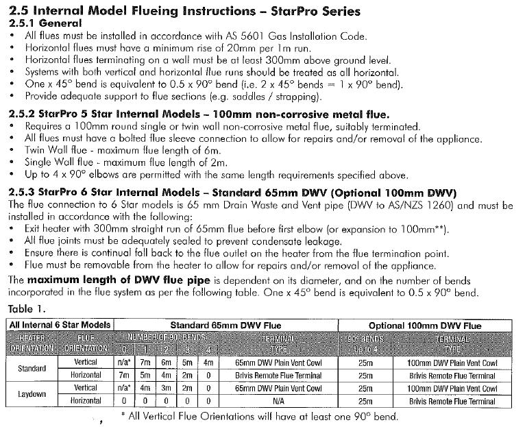
97 8. FLUEING REQUIREMENTS 97
98 "IMPORTANT NOTICE: This document is a guide only. Laws, regulations and industry standards can vary between States and Territories. Accordingly, this guide must be read in conjunction with, and subject to, all laws, regulations and industry standards applicable in the State or Territory in which the products are installed. You must ensure that the installation of the products will comply with those laws, regulations and standards, and that the products recommended to customers are fit for the purpose for which they are intended. 98
99 Notes: 99

100 For all your Sales and Service enquiries call us on 1300 BRIVIS ( ) Brivis Technical Support or Brivis Australia 61 Malcolm Rd Braeside Victoria 3195 Australia 1300 BRIVIS ( ) Fax: +61 (03) Brivis New Zealand Distributor: Warm Air Ltd 69 Marsden Street Lower Hutt 5010 New Zealand PO Box Wellington Mail Centre Wellington 5043 New Zealand 0800 WARMAIR ( ) Ph: +64 (04) Fax: +64(04) Brivis South Africa Distributor: Lorenz and Associates Northlands Deco Park Cnr Witkoppen and Newmarket Roads North Riding, Johannesburg South Africa BRIVIS ( ) Ph: +27 (011) Fax: +27 (011) Brivis Climate Systems Pty. Ltd All rights reserved. No part of these documents may be used in any way or form without prior written consent from Brivis Climate Systems Pty Ltd. August 2013 Brivis Pty Ltd ABN AU
Service Manual Brivis BX5
 Service Manual Brivis BX5 Service shall be carried out only by Authorised Personnel. This Service Manual must NOT be left with the Owner, or distributed to other persons not permitted to obtain this information
Brivis Service Manual CC3 Gas Ducted Heater Compact Classic
 Brivis Service Manual CC3 Gas Ducted Heater Compact Classic Service shall be carried out only by Authorised Personnel. This Service Manual must NOT be left with the Owner, or distributed to other persons
Service Manual 4 Heater MPS & AUTO EMS Vol. 2 of 2 Approved Issue 10 Printed 13-Feb-14 11:52:53 AM 1
 Service Manual 4 Heater MPS & AUTO EMS Vol. 2 of 2 Approved Issue 10 Printed 13-Feb-14 11:52:53 AM 1 Index BULLETINS & SERVICING INSTRUCTIONS......... 4-19 MPS - Fit AFRO and New Style Burner.........
Brivis Service Manual BX3 Buffalo Gas Ducted Heater
 Brivis Service Manual BX3 Buffalo Gas Ducted Heater Service shall be carried out only by Authorised Personnel. This Service Manual must NOT be left with the Owner, or distributed to other persons not permitted
Brivis Service Manual
 Brivis Service Manual EMS (2) Energy M anagem ent Syst em Servicing shall be carried out only by A uthorised Personnel. T his Service Manual must N O T be left with the O wner. Service Manual 19 Heater
Service Manual 3 Heater MPS & AUTO EMS Vol 1 of 2 Approved Issue 10 Printed 13/02/ :52:21 AM 1
 Service Manual 3 Heater MPS & AUTO EMS Vol 1 of 2 Approved Issue 10 Printed 13/02/2014 11:52:21 AM 1 Index Pages INTRODUCTION:......... 4-5 THE N-G1/lo INSTALLATION & SET-UP INSTRUCTIONS:......... 6-8
Service Manual - Heater - Electronic (TEK 300) Series - No.2 Issue 6 Printed 2/13/ :51:58 AM 1
 Series - No.2 Issue 6 Printed 2/13/ :51:58 AM 1") Service Manual - Heater - Electronic (TEK 300) Series - No.2 Issue 6 Printed 2/13/2014 11:51:58 AM 1 Index Page Technical Information Buffalo 3-6 Wombat 7-11 Upflow 12-14 Downflow 15-16 Airflow Chart 17
Service Manual - Heater - Electronic (TEK 300) Series - No.2 Issue 6 Printed 2/13/2014 11:51:58 AM 1 Index Page Technical Information Buffalo 3-6 Wombat 7-11 Upflow 12-14 Downflow 15-16 Airflow Chart 17
G34M Bulletin #69/ August 2003
 ENGINEERING DATA G34M MULTI POSITION GAS FURNACE 12.4 to 31.0 kw Output 52.7 to 131.9 Mj Input 3.5 to 17.6 kw Nominal Add-on Cooling GAS FURNACES 50 Hz G34M Bulletin #69/490045 August 2003 Typical Applications
Service Guide. Service Guide NATIONAL COMFORT PRODUCTS GAS & ELECTRIC MODELS. 2nd Edition
 2nd Edition Service Guide Thru-the-Wall Packaged Heating & Cooling Units Service Guide GAS & ELECTRIC MODELS NATIONAL COMFORT PRODUCTS HEATING & A/C EQUIPMENT National Comfort Products A Division of National
REPLACEMENT PARTS MANUAL
 Date Issued Product Section Details Section No 1-Apr-09 H10.11 B5 High Efficiency Ducted Gas Central Heating Issue Status Page A Models: B5 15, 21, 21xa, 30, 30xa, 35 5120003 BV5 15I 15Kw Internal 5120013
B-40/B-41 Modulating Temperature Controller
 INSTALLATION & OPERATING INSTRUCTIONS B-40/B-41 Modulating Temperature Controller For Raytherm Boilers & Water Heaters H2 514-4001 WH2 2100-4001 Catalog No. 5000.70 Effective: 12-21-11 Replaces: NEW P/N
SIME FORMAT WALL HUNG BOILERS MODEL 34i AND MODEL 34e. cod A
 cod. 6272262A GENERAL DATA Heating Data Heat Output Input (Adjustable) (Adjustable) Format 34i 11.2 34KW 45 145MJ/hr Format 34e 11.2 34KW 45 145MJ/hr General Specifications FORMAT 34i 34e Main burner injectors
GAS DUCTED HEATER TB SERIES
 GAS DUCTED HEATER TB SERIES Home Owners Guide APRIL 2002 N837 FROM YOUR LOCAL GAS SUPPLIER XXX MJ/m 3 PER YEAR Part No... 9601055 INTRODUCTION Congratulations on choosing a Braemar Gas Ducted Heating Unit.
Brivis Inverter Icebox
 Brivis Inverter Icebox R410A INSTALLATION INSTRUCTIONS PLEASE READ THESE INSTRUCTIONS CAREFULLY BEFORE INSTALLING & USING THIS PRODUCT Bonus offer when you register your product online brivis.com.au Table
Aqua Balance. AquaBalance TM CONTROL MODULE QUICK START GUIDE LEGEND
 Aqua Balance AquaBalance TM CONTROL MODULE QUICK START GUIDE 10 1 Domestic Hot Water temperature setpoint decreasing button 2 Domestic Hot Water temperature setpoint increasing button 3 Central Heating
LAYOUT BRAEMAR ECOSTAR GAS SPACE HEATER AND WALL FURNACE OPERATING INSTRUCTIONS FOR MODELS SH18, SH25 AND WF25 HEATED AIR OUTLET HEATER CONTROL PANEL
 LAYOUT BRAEMAR ECOSTAR GAS SPACE HEATER AND WALL FURNACE OPERATING INSTRUCTIONS FOR MODELS SH18, SH25 AND WF25 HEATER CONTROL PANEL HEATED AIR OUTLET Installation date: Installer: Installer phone No: Heater
Installation, Operating and Maintenance Manual
 STATUS ZONES CONTROLS FIRE FAULT DISABLED FIRE 1 2 3 4 5 6 7 8 TEST FAULT DISABLED 1 5 BUZZER SILENCE RESET 1 2 TEST 2 6 LAMP TEST 3 SUPPLY 3 7 SYSTEM FAULT 4 8 SOUNDERS ACTIVATE/ SILENCE 4 FAULTS INSTRUCTIONS
HOME OWNER S MANUAL DUCTED GAS HEATER. (with MagIQtouch Controller)
") HOME OWNER S MANUAL DUCTED GAS HEATER (with MagIQtouch Controller) This document is the Owner s Manual for your ducted gas heater. HEATER IDENTIFICATION AND INSTALLATION Model No Serial No: This information
HOME OWNER S MANUAL DUCTED GAS HEATER (with MagIQtouch Controller) This document is the Owner s Manual for your ducted gas heater. HEATER IDENTIFICATION AND INSTALLATION Model No Serial No: This information
Brivis Service Manual
 ISO Documents Last modified by: Felicity Devine Date last modified: 23/02/2005 Document: Brivis Service Manual Evaporative Cooler Contour N-E3 & BC-E1 1999 Supplement This manual is to be used in conjunction
Brivis Touch Controller. Installer Manual
 Brivis Touch Controller Installer Manual Brivis Touch Controller Kit Scope Please read these instructions carefully before installing this product. This manual covers the installation of the wall mounted
Installation Instructions Horizon Natural Draft Electronic Ignition Gas Fireplaces
 Installation Instructions Horizon Natural Draft Electronic Ignition Gas Fireplaces Installation Instructions Horizon Natural Draft Electronic Ignition 3 Sided Gas Fireplaces Natural Draft Electronic Ignition
CONTROL PANEL INTERFACE ACTIVATE THE GENERATOR DISPLAY INTERFACE MENUS. Control Panel USING THE AUTO/OFF/MANUAL SWITCH
 CONTROL PANEL INTERFACE USING THE AUTO/OFF/MANUAL SWITCH With the switch set to AUTO, the engine may crank and start at any time without warning. Such automatic starting occurs when utility power source
INSTRUCTION MANUAL FOR OIL BURNER MODELS
 INSTRUCTION MANUAL FOR OIL BURNER MODELS X400 Bio B10 E90-803-001-001-03 Rev 13-1 - Contents Technical specifications Technical data... 3 Working field... 3 Dimensions... 4 Head and electrode settings...
Model Universal Oil Primary Control
 Model 70200 Universal Oil Primary Control Installation and Operating Instructions For Use By Qualified Service Technicians Only Universal Replacement for Carlin, Beckett, Honeywell and ICM Controls On-Board
G60UH(X) WARNING. WARNING Sharp edges. Be careful when servicing unit to avoid sharp edges which may result in personal injury. Service Literature
 WARNING. WARNING Sharp edges. Be careful when servicing unit to avoid sharp edges which may result in personal injury. Service Literature") Service Literature Corp. 0204 L2 Revised 11 2006 G60UH(X) G60UH(X) SERIES UNITS G60UH(X) series units are mid efficiency gas furnaces used for upflow or horizontal applications only, manufactured with
Service Literature Corp. 0204 L2 Revised 11 2006 G60UH(X) G60UH(X) SERIES UNITS G60UH(X) series units are mid efficiency gas furnaces used for upflow or horizontal applications only, manufactured with
OWNER S MANUAL Manufactured Home Downflow Gas Furnace: MGD-B Series
 OWNER S MANUAL Manufactured Home Downflow Gas Furnace: MGD-B Series Heat Controller, Inc. 1900 Wellworth Ave. Jackson, MI 49203 (517)787-2100 www.heatcontroller.com Owner s Manual MGD-B SERIES GAS FURNACE
Q - Series Boiler. Troubleshooting Manual
 Q - Series Boiler Troubleshooting Manual WARNING There are a number of live tests that are required when fault finding this product. Extreme care should be used at all times to avoid contact with energized
SKYPAK II, 3 Ton Series, gives you a
 SKYPAK II 3 ton Heating And Cooling self-contained Package SKYPAK II, 3 Ton Series, gives you a complete air-conditioning and heating system as an all in one package unit. Designed for convenient through-the-wall
Mikrofill Ethos Condensing combination boiler. Maintenance Instructions 24cc
 Mikrofill Ethos Condensing combination boiler Maintenance Instructions 24cc IMPORTANT Benchmark Installation, Commissioning and Service Record Log Book is enclosed in your customer information pack. This
MODEL SF-10 CONTROL OPERATION AND INSTRUCTION MANUAL
 MODEL SF-10 CONTROL OPERATION AND INSTRUCTION MANUAL The SF-10 Temperature Control () is an efficient boiler operator with a digital LCD display with backlight, a boiler pump output, and an alarm. The
Rapid Response Series (RR e & RR i) OPERATING MANUAL
 OPERATING MANUAL") Rapid Response Series (RR e & RR i) OPERATING MANUAL STADT INDUSTRIES PTY. LTD. MF-01 18/07/04 Operating Manual RR Series Stadt High Efficiency Central Heater. CONTENTS A): Introduction A: Introduction
Rapid Response Series (RR e & RR i) OPERATING MANUAL STADT INDUSTRIES PTY. LTD. MF-01 18/07/04 Operating Manual RR Series Stadt High Efficiency Central Heater. CONTENTS A): Introduction A: Introduction
Exhaust Duct Design Page 1 of (C)
") Exhaust Duct Design Page 1 of 16 2016-10-07 (C) Oven Exhaust Guide Version: R5 Exhaust Duct Design The following section is for your guidance in establishing a design to suit your Exhaust duct design requirements.
Exhaust Duct Design Page 1 of 16 2016-10-07 (C) Oven Exhaust Guide Version: R5 Exhaust Duct Design The following section is for your guidance in establishing a design to suit your Exhaust duct design requirements.
Quickheat 30 weather compensated boiler control
 Quickheat 0 weather compensated boiler control A compact and sophisticated heating controller The compact KM controller is designed for the control of fan assisted boilers with modulating burners. The
TWINTEMP JR. HYDRONIC SYSTEM 2/2013
 TWINTEMP JR. HYDRONIC SYSTEM 2/2013 TwinTemp Description of Operation and Sequence of Operation Technical Description of Operation The TwinTemp systems provide quiet space heating utilizing liquid to air
Technical Manual MAY 2008 Edition
 SPECIFICATION - GMP SERIES MULTI POSITION INDUCED DRAFT GAS FURNACE EARLY MODELS WITH HOT SURFACE IGNITION AND LATER MODELS WITH DIRECT SPARK IGNITION A.G.A. Approval No. 5113 Technical Manual MAY 2008
Packaged Gas/Electric Units. Owner s Guide to Operating and Maintaining Your Gas/Electric Unit
 Packaged Gas/Electric Units Owner s Guide to Operating and Maintaining Your Gas/Electric Unit ELECTRICAL SHOCK HAZARD. FIRE OR EXPLOSION HAZARD Disconnect power at fuse box or service panel before performing
! WARNING To avoid risk of electrical shock, personal injury or death; disconnect power to range before servicing, unless testing requires power.
 Technical Information Electric Slide-In Range JES8850BC* JES9900BC* JES9860BC* Due to possibility of personal injury or property damage, always contact an authorized technician for servicing or repair
! WARNING To avoid risk of electrical shock, personal injury or death; disconnect power to range before servicing, unless testing requires power.
 Technical Information Electric Slide-In Range JES9750BA* JES9860BA* Due to possibility of personal injury or property damage, always contact an authorized technician for servicing or repair of this unit.
Demand Duo Principle of Operation:
 Page 1 of 25 8/23/2010 Contents: Demand Duo Principle of Operation:... 3 Schematic of Demand Duo:... 4 Demand Duo Fault Finding Check List:... 4 Basic operating principle of Demand Duo Thermostat:... 4
INSTRUCTION MANUAL FOR OIL BURNER MODELS
 INSTRUCTION MANUAL FOR OIL BURNER MODELS X500 Bio B10 E90-803-001-001-00 Rev 7-1 - Contents Technical specifications Technical data... 3 Working field... 3 Dimensions... 4 Head and electrode settings...
HEATING. Owner s Manual PLEASE READ THESE INSTRUCTIONS CAREFULLY BEFORE USE. Bonus offer when you register your product online brivis.com.au.
 HEATING Owner s Manual PLEASE READ THESE INSTRUCTIONS CAREFULLY BEFORE USE Bonus offer when you register your product online brivis.com.au a company Index Introduction... 1 Privacy Notification Product
MAINTENANCE AND SERVICE GUIDE
 c Dimensions MAINTENANCE AND SERVICE GUIDE System II 80 and 100 Central Heating Fanned Flue Boiler Sizes in mm Flue types: C 12 or 42: horizontal C 32 xx: vertical concentric C 32 xy: Twin flue Boiler
Packaged Gas/Electric
 Packaged Gas/Electric Units Owner's Guide to Operating and Maintaining Your Gas/Electric Unit ELECTRICAL SHOCK HAZARD. FIRE OR EXPLOSION HAZARD Failure to follow this warning can result in Disconnect power
13 GEP A L P - 1 A
 PRODUCT SPECIFICATIONS PACKAGED GAS / ELECTRIC 3GEP MERIT SERIES Residential - R-40A Bulletin No. 20602 December 202 Supersedes October 202 SEER - 3.00 AFUE - 80% 2 to 5 Tons Cooling Capacity - 22,800
SKYPAK II Heating & Cooling Self Contained Packages
 SKYPAK II Heating & Cooling Self Contained Packages SKYPAK II gives you a complete airconditioning and heating system as an all-in-one package unit. Designed for conventional through-the-wall installation
DC50X2 Models 50 Pound Stacked Commercial Dryer. Troubleshooting,Fault Codes, and Schematics. Starting serial number Part # /13
 DC50X2 Models 50 Pound Stacked Commercial Dryer Troubleshooting,Fault Codes, and Schematics Starting serial number Trouble Shooting Electronic Control Diagnostic s The electronic control has 6 diagnostic
USER GUIDE. IMAX XTRA EL kW. For Installation Guide see reverse of book
 USER GUIDE IMAX XTRA EL 320-620kW For Installation Guide see reverse of book When replacing any part on this appliance, use only spare parts that you can be assured conform to the safety and performance
- Data Brochure Boiler Control 274
 - Data Brochure Boiler Control 274 274_D 03/17 The Boiler Control 274 operates up to four on/off boilers to provide outdoor reset operation, domestic hot water and setpoint operation with priority. When
CATALOG. SKYPAK Self-Contained Heating/Cooling Units
 CATALOG SKYPAK Self-Contained Heating/Cooling Units FORM SK145.00-EG6 (1211) TABLE OF CONTENTS SKYPAK Self-Contained Heating/Cooling Units Introduction...3 Product Overview...3 Nomenclature...4 SKYPAK
SKYPAK II, 3 Ton Series, gives you a
 SKYPAK II 3 ton Heating And Cooling self-contained Package SKYPAK II, 3 Ton Series, gives you a complete air-conditioning and heating system as an all in one package unit. Designed for convenient through-the-wall
G71MPP WARNING. WARNING Sharp edges. Be careful when servicing unit to avoid sharp edges which may result in personal injury. Service Literature
 Service Literature Corp. 0804 L2 Revised 05 05 2008 G71MPP G71MPP SERIES UNITS G71MPP series units are high efficiency multi position (upflow, downflow, horizontal right and left) gas furnaces equipped
8+* Bulletin No November 1997
 ENGINEERING DATA VALUE 80Z UP-FLOW/HORIZONTAL GAS FURNACES *80.0 to 80.5% A.F.U.E. 45,000 to 20,000 Btuh (3.2 to 32.2 kw) Input Heating Capacity -/2 thru 6 Tons (3.5 thru 2. kw) Nominal Add-on Cooling
EBC20. Instructions for fitting, installation and operation. Read and save these instructions!
 EBC20 UK Instructions for fitting, installation and operation Read and save these instructions! 2 3002878 EBC20 UK 290415 1. Product information............................................... 4 1.1 Delivery.............................................................
Fig. 1 - Unit PGD4, PGS4, WPG4
 OWNER S MANUAL 14 SEER Single -Package Air Conditioner and Gas Furnace System with R -410A Refrigerant Single Phase 2 to 5 Nominal Tons Three Phase 3 to 5 Nominal Tons PGD4andPGS4SeriesE,WPG4SeriesB Fig.
USER'S MANUAL PGE Single Package Rooftop
 USER'S MANUAL PGE Single Package Rooftop Gas Heating/Electric Cooling Units Sizes 036-150 3 to 12-1/2 Tons NOTE TO INSTALLER: This manual should be left with the equipment owner. WARNING: If the information
Carbon Monoxide Transmitter
 Introduction The CO Transmitter uses an electrochemical sensor to monitor the carbon monoxide level and outputs a field-selectable 4-20 ma or voltage signal. The voltage signal may also be set to 0-5 or
User s Information Manual
 62DA,DB,DC,DD07-38 Vertical or Horizontal Dedicated 100% Outdoor Air Unit with Optional Gas Heat User s Information Manual NOTE TO INSTALLER This manual should be left with the equipment owner. : If the
USER S, MAINTENANCE and SERVICE INFORMATION MANUAL
 CONTENTS SAFETY INFORMATION................ 2 FOR YOUR SAFETY....................... 2 SYSTEM OPERATION.................. 2 THERMOSTATS.......................... 2 INTERMITTENT IGNITION DEVICE...........
G60UHV(X) WARNING. WARNING Sharp edges. Be careful when servicing unit to avoid sharp edges which may result in personal injury. Service Literature
 WARNING. WARNING Sharp edges. Be careful when servicing unit to avoid sharp edges which may result in personal injury. Service Literature") Service Literature Corp. 0124 L11 Revised 11 2006 G60UHV(X) G60UHV(X) SERIES UNITS G60UHV(X) series units are mid efficiency gas furnaces used for upflow or horizontal applications only, manufactured with
Service Literature Corp. 0124 L11 Revised 11 2006 G60UHV(X) G60UHV(X) SERIES UNITS G60UHV(X) series units are mid efficiency gas furnaces used for upflow or horizontal applications only, manufactured with
User's Infomation Manual
 User's Infomation Manual 574A GAS HEATING/ELECTRIC COOLING Cancels: OM01-69 OM10-28 02-07 NOTE: Read the entire instruction manual before starting the installation. SAFETY CONSIDERATIONS Note to Installer:
BG2000S PRE-MIX GAS BURNER
 BG000S PRE-MIX GAS BURNER INSTALLATION OPERATION & MAINTENANCE DOCUMENTATION STOKVIS ENERGY SYSTEMS 96R WALTON ROAD EAST MOLESEY SURREY KT8 0DL TEL: 08707 707 77 FAX: 08707 707 767 E-MAIL:info@stokvisboilers.com
48TF GAS HEATING/ ELECTRIC COOLING UNITS
 48TF-4SB 48TF004-014 GAS HEATING/ ELECTRIC COOLING UNITS PERFORMANCE DATA CERTIFIED DIMENSION PRINTS CERTIFIED ROOF CURB DIMENSION PRINTS Copyright 2005 Carrier Corporation Syracuse, New York 13221 Form
TM NOVEMBER 1986 HEATER, SPACE, MULTIFUEL WITH BLOWER, 60,000 BTU/HR, 120 V UH-68G ( )
") OPERATOR S, UNIT, AND INTERMEDIATE MAINTENANCE MANUAL TABLE OF CONTENTS i OPERATING INSTRUCTIONS 2-1 UNIT MAINTENANCE INSTRUCTIONS 3-1 INTERMEDIATE MAINTENANCE INSTRUCTIONS 4-1 MAINTENANCE ALLOCATION CHART
OPERATOR S, UNIT, AND INTERMEDIATE MAINTENANCE MANUAL TABLE OF CONTENTS i OPERATING INSTRUCTIONS 2-1 UNIT MAINTENANCE INSTRUCTIONS 3-1 INTERMEDIATE MAINTENANCE INSTRUCTIONS 4-1 MAINTENANCE ALLOCATION CHART
USER S, MAINTENANCE and SERVICE INFORMATION MANUAL
 CONTENTS SAFETY INFORMATION................ 2 FOR YOUR SAFETY...................... 2 SYSTEM OPERATION.................. 2 THERMOSTATS.......................... 2 INTERMITTENT IGNITION DEVICE..........
FEATURES. Gas Furnace provides the efficiency customers want with 78% Annual Fuel Utilization Efficiency (AFUE).
.") This document was created with FrameMaker 4.0.4 SIZES AVAILABLE: 024065 through 060150 EFFICIENCY: IGNITION: HEAT EXCHANGER: CONTROL BOARD: The GA1A Induced-Combustion Gas Furnace provides the efficiency
This document was created with FrameMaker 4.0.4 SIZES AVAILABLE: 024065 through 060150 EFFICIENCY: IGNITION: HEAT EXCHANGER: CONTROL BOARD: The GA1A Induced-Combustion Gas Furnace provides the efficiency
Light oil burners. One stage operation
 Installation, use and maintenance instructions Light oil burners One stage operation CODE MODEL TYPE 3505 RDB CF 38 50 T3 350050 RDBR CF 6 50 TR 35050 RDBR CF 33 50 TR 35050 RDBR CF 38 50 T3R 350650 RDBR
POWER VENTER. Model: PVE Series
 POWER VENTER Model: PVE Series CONTENTS Typical Venting System Components... System Operation... Power Venter Sizing... Installation Safety Instructions... Installation of Power Venter... Connecting Power
G60UH(X) WARNING. WARNING Sharp edges. Be careful when servicing unit to avoid sharp edges which may result in personal injury. Service Literature
 WARNING. WARNING Sharp edges. Be careful when servicing unit to avoid sharp edges which may result in personal injury. Service Literature") Service Literature Corp. 0204 L2 Revised 09 2006 G60UH(X) G60UH(X) SERIES UNITS G60UH(X) series units are mid efficiency gas furnaces used for upflow or horizontal applications only, manufactured with
Service Literature Corp. 0204 L2 Revised 09 2006 G60UH(X) G60UH(X) SERIES UNITS G60UH(X) series units are mid efficiency gas furnaces used for upflow or horizontal applications only, manufactured with
ATMOSPHERIC GAS BOILER INSTALLATION, OPERATING AND MAINTENANCE MANUAL
 STREBEL GENEVA CE ATMOSPHERIC GAS BOILER INSTALLATION, OPERATING AND MAINTENANCE MANUAL INDEX TABLE 1 TECHNICAL DATA SECTION 1 SECTION 2 SECTION 3 SECTION 4 SECTION 5 SECTION 6 SECTION 7 SECTION 8 SECTION
Single stage operation oil burner
 Installation & Operating Manual Single stage operation oil burner WARNING NON-RETROFIT APPLICATIONS If this burner is being installed in a packaged unit (ie. burner comes with a boiler or furnace), follow
Great Britain en. Installation, user and service manual. Control panel HMI Gas 310/610 ECO PRO
 Great Britain en Installation, user and service manual Control panel HMI Gas 310/610 ECO PRO Dear Customer, Thank you very much for buying this appliance. Please read through the manual carefully before
T-CLASS GAS-FIRED UNIT HEATERS Separated Combustion - Direct Vent - Horizontal - 60 HZ. Thermal Efficiency - up to 82% Input - 40,000 to 300,000 Btuh
 PRODUCT SPECIFICATIONS GAS UNIT HEATERS / DUCT FURNACES TU T-CLASS GAS-FIRED UNIT HEATERS Separated Combustion - Direct Vent - Horizontal - 60 HZ Bulletin No. 20402 November 207 Supersedes November 206
Owner s Information Manual
 48ES---A and 48VL---A Comfort and Performance 13 and 14 SEER Single Packaged Air Conditioner and Gas Furnace System With Puron (R---410A) Refrigerant Single and Three Phase 2---5 Nominal Tons (Sizes 24---60)
Brivis Service Manual
 Brivis Service Manual Evaporative Cooler AD/C 5 Series N-E1 & Tekelek 461 1999 Supplement This manual is to be used in conjunction with the Service Manual 12 - Cooler - AD / CC (series 4 & 5) Service Manual
FEC400 Series. Installation Manual
 FEC400 Series Conventional microprocessor controlled fire detection and alarm panels with extinguishing control Installation Manual Version 2.3 / August 2004 Aritech is a GE Interlogix brand. http://www.geindustrial.com/ge-interlogix/emea
SERIES VAC Microprocessor-Based Direct Spark Ignition Control with Inducer Blower Relay FEATURES APPLICATIONS SPECIFICATIONS DESCRIPTION
 R SERIES 35-61 24 VAC Microprocessor-Based Direct Spark Ignition Control with Inducer Blower Relay F-35-61 August 2015 FEATURES Safe start with DETECT-A-FLAME flame sensing technology Custom pre-purge
Direct Vent Service Manual
 RHFE-551FA RHFE-1001FA RHFE-1001FA/VA RHFE-201FA RHFE-263FA, FAII RHFE-431FA, FAII, FAIII, WTA Direct Vent Service Manual RHFE-556FA, FAII, FAIII, FTRA, FTRAIII, WTA RHFE-1004FA ES08 ES11 ES17 EX17 ES22
PNC 1000 SERIES 2, 4, 8 Zone Fire Alarm Control Panel
 PNC 1000 SERIES 2, 4, 8 Zone Fire Alarm Control Panel INSTALLATION, OPERATION AND MAINTENANCE MANUAL Version: CN-PM-1000.VER1.1-12/2012 EN54 INFORMATION In accordance with EN 54-2 clause 13.7, the maximum
TWZ/CT/ODV Series. Oil-Fired Hot Water Boilers (Less Tankless Heater) These instructions must be affixed on or adjacent to the boiler
 These instructions must be affixed on or adjacent to the boiler") D E S I G N E D T O L E A D TWZ/CT/ODV Series Oil-Fired Hot Water Boilers (Less Tankless Heater) Installation Supplement for boilers equipped with honeywell L7248L 2012 Compliant boiler control These instructions
D E S I G N E D T O L E A D TWZ/CT/ODV Series Oil-Fired Hot Water Boilers (Less Tankless Heater) Installation Supplement for boilers equipped with honeywell L7248L 2012 Compliant boiler control These instructions
RGE 13 A T - 1 A
 PRODUCT SPECIFICATIONS PACKAGED GAS / ELECTRIC 3GEP / RGE3 Rooftop Units 60HZ Bulletin No. 2063 December 202 Supersedes October 202 MODEL NUMBER IDENTIFICATION -PHASE MODELS SEER - 3.00 (3GEP Shown) AFUE
Construction Electrical
 INDEECO offers a broad range of electrical components for temperature, safety, and power control. For most applications, the Control Option system, described in the previous section, makes it easy to specify
ANALOX SENSOR TECHNOLOGY LTD ANALOX DD1101 INSTALLATION & OPERATION MANUAL
 ANALOX SENSOR TECHNOLOGY LTD ANALOX DD1101 INSTALLATION & OPERATION MANUAL SAFETY WARNING Please Refer to the Safety Warning in Section 7.1 regarding the chemicals in the oxygen sensor Analox Sensor Technology
Electrical. Bi-Metallic Thermal Cutouts. Linear Thermal Cutouts
 Standard Construction Control Options HEATREX offers a broad range of electrical components for temperature, safety, and power control. For most applications, the Control Option system, described in the
G51MP WARNING. WARNING Sharp edges. Be careful when servicing unit to avoid sharp edges which may result in personal injury. Service Literature
 Service Literature Corp. 0307 L5 Revised 11 2006 G51MP SERIES UNITS G51MP G51MP series units are high efficiency multiple position (upflow, downflow, horizontal left and horizontal right) gas furnaces
Suburban RV FURNACES SERVICE MANUAL
 Suburban RV FURNACES SERVICE MANUAL DD-17DSI DD-17DSIW NT-12S/SE NT-16S/SE NT-20S/SE NT-24SP NT-30SP NT-34SP NT-40 P-30S/40 SF-20 SF-25 SF-30 SF-35 SF-42 SF-20F SF-25F SF-30F SF-35F SF-42F SH-35 SH-42
AFUE 95% Heating Input 50,000 to 200,000 Btuh
 PRODUCT SPECIFICATIONS WATER HEATERS / BOILERS GWM-IE Gas-Fired, Modulating, Condensing, Wall Hung Hot Water Boiler Bulletin No. 210650 March 2018 Supersedes December 2015 AFUE 95% Heating Input 50,000
Heat 45 & 55. User Instructions FAN POWERED HIGH EFFICIENCY MODULATING DOMESTIC CONDENSING GAS COMBINATION BOILER
 Heat 45 & 55 User Instructions FAN POWERED HIGH EFFICIENCY MODULATING DOMESTIC CONDENSING GAS COMBINATION BOILER CE/PI No. 86-CN-69 Heat 45 - GC No. 41-930-40 Heat 55 - GC No. 41-930-41 These instructions
Refrigeration Controller Operator s Manual (HRC) PO Box 6183 Kennewick, WA
 PO Box 6183 Kennewick, WA") Refrigeration Controller Operator s Manual (HRC) PO Box 6183 Kennewick, WA 99336 www.jmcvr.com 1-509-586-9893 Table of Contents TABLE OF FIGURES...1 OVERVIEW OF THE HRC CAPABILITIES...2 INSTALLATION AND
Refrigeration Controller Operator s Manual (HRC) PO Box 6183 Kennewick, WA 99336 www.jmcvr.com 1-509-586-9893 Table of Contents TABLE OF FIGURES...1 OVERVIEW OF THE HRC CAPABILITIES...2 INSTALLATION AND
DualComfort. Hot or cold, your home will feel perfect. Create that perfect feeling. Combination Climate SyStem
 DualComfort Combination Climate SyStem Create that perfect feeling Hot or cold, your home will feel perfect. Create the perfect feeling of comfort throughout your home with a Brivis DualComfort whole home
95M-200. Gas-Fired Direct Vent Modulating Hot Water Boiler. Control Manual And Troubleshooting Guide. P/N , Rev.
 95M-200 Gas-Fired Direct Vent Modulating Hot Water Boiler Control Manual And Troubleshooting Guide P/N 24000604, Rev. C [04/09] WARNING! Revise boiler control parameters only if you fully understand the
Analog Room Pressure Monitor RPC Series
 Description The Room Pressure Monitor is used to measure differential pressure in the range of 0.125 to 1"wc or 30 to 250 Pa. It combines precision high sensitivity silicon sensing capabilities and the
FURNACE OPERATION OVERVIEW
 You ve had a fun day but now it s getting chilly, so you decide to fire up the RV furnace. You flip the thermostat on, set the temperature and wait expectantly, but no heat comes from the outlets. It s
Flue Dilution Fans. Specialists in Air Movement Technology. IMPROVED GBDF MK5 Now includes a Pressure Safety Switch and easier Electrical Connections
 Now includes a Pressure Safety Switch and easier Electrical Connections Flue Dilution Fans VISIT US AT www.airflow.com UK SALESLINE 0845 330 1047 Specialists in Air Movement Technology SAFETY - NEW Differential
STM Department TRAINING MODULE. : instantaneous. Version 1.0, Jan 2006
 TRAINING MODULE Product group Group Project Name Sales designation Production unit : Wallhung boiler : instantaneous : MX2 COMFORT : : ST BRIEUC (France) Version 1.0, Jan 2006 - 2 - Update VERSION DATE
PELLET BURNER PV 350
 PELLET BURNER PV 350 INSTRUCTION MANUAL v1.1 1 PRODUCT DESCRIPTION...3 2 SAFETY RULES...3 3 WARNINGS...4 4 INSTALLATION INSTRUCTIONS...5 4.1 BOILER REQUIREMENTS...5 4.2 PELLET CONTAINER...6 4.3 INSTALLATION
HEATING & ADD-ON COOLING
 HEATING & ADD-ON COOLING Welcome to brivis 50 Years of Innovation Designed and Made in Australia Excellence in Quality and Manufacturing Commitment to the Environment Brivis has been helping people choose
Brivis Classic Ducted Gas Heater
 Brivis Classic Ducted Gas Heater Installer s Manual PLEASE READ THESE INSTRUCTIONS CAREFULLY BEFORE INSTALLING THIS PRODUCT Scope This Installer s Manual is intended to be used as a guideline for the installation
PVE SERIES POWER VENTER SYSTEM MANUAL
 PVE SERIES POWER VENTER SYSTEM MANUAL Contents Page I. Typical Venting System Components 2 II. System Operation 3 III. Power Venter Sizing 3,4 IV. Installation Safety Instructions 5,6 V. Installation of
Hurlcon Gas Fired Hot Water Boiler H120 & H150 S & B Models
 Hurlcon Gas Fired Hot Water Boiler H120 & H150 S & B Models INSTALLATION AND OPERATING INSTRUCTIONS HURLCON Manufacturing & Sales Pty. Ltd. A.B.N. 97 007 284 504 48 Hanna Street, Noble Park, VICTORIA.
U n i t H e at e r s
 Unit Heaters LF Models Enduring performance Allied commercial unit heaters are built to last, season after season Designed and built for durability and peak performance, Allied Commercial unit heaters