BLUE FLAME CROP DRYER
|
|
|
- Maude Bridges
- 6 years ago
- Views:
Transcription
1 BLUE FLAME CROP DRYER Installation & Operating Instructions For Models: 108G-001A -- LP, 1 PHASE 108H-001A -- LP, 3 PHASE 109G-001A -- NG, 1 PHASE 109H-001A -- NG, 3 PHASE Shivvers Incorporated 614 West English St. Corydon, IA (641) P /20/04
2 TABLE OF CONTENTS PAGE INTRODUCTION SAFETY INFORMATION LOCATION OF SAFETY DECALS IDENTIFICATION OF PARTS MECHANICAL INSTALLATION DRYING BIN LAYOUT LIQUID PROPANE INSTALLATION AND GAS HOOKUP 16 NATURAL GAS INSTALLATION AND GAS HOOKUP.17 GRAIN HIGH LIMIT INSTALLATION 18 ELECTRICAL INSTALLATION INCOMING POWER HOOKUP CONTROL TRANSFORMER WIRING CONTROL WIRING. 22 CONTROL WIRING TO COMPUDRY COMMAND CENTER INITIAL CHECKOUT.. 25 OPERATING INSTRUCTIONS MAINTENANCE TROUBLESHOOTING SCHEMATIC
3 INTRODUCTION COMPLETELY READ THIS MANUAL AND THE OPERATOR S SAFETY MANUAL (P ), BEFORE INSTALLING OR USING THE BLUE FLAME CROP DRYER. The Blue Flame crop dryer uses a vane axial fan blade mounted on a Hp, 3600 RPM, electric motor. It has a stainless steel burner element which is capable of up to 3.65 Million BTU's. Liquid Propane models have a built in vaporizer. It is possible to piggy back or turbo-boost the Blue Flame with another motor and fan blade for higher static pressure applications. This series of Blue Flame crop dryers is similar to the Blue Flame's manufactured by Shivvers in the past, except for the control circuitry. This series started with a limited production in the year These dryers use a flame sensing system called flame rectification. It eliminates the old flame sensing switch and replaces it with a flame rod. There are no moving parts in the flame rod. It just has to be in the flame but not touching the burner or housing. The flame sense module will apply an AC current to the flame rod. If a flame is present, the flame will rectify or change it to a DC current. If the flame sense module detects this DC current, it will turn off the ignition transformer and the burner will continue to burn. If the DC current is not detected, the flame sense module will lockout the burner, and the burner power switch will have to be shut off for a few seconds, then turned back on, to reset the module. 2
4 SAFETY INFORMATION The operator of this machinery must assume the responsibility for his own safety, and that of those who are working with him. He must also make sure the equipment was installed properly. Factors that contribute to the overall safety of operation are: proper use, maintenance, and frequent inspection of the equipment. All of these are the operator's responsibility. If any items covered in this manual are not completely understood, or there is a concern with the safety of the product, contact SHIVVERS Incorporated at the address shown on the front cover. SHIVVERS is genuinely interested in providing the safest practical equipment to our customers. If you have a suggestion which you believe will enhance the safety of this product, please write us and let us know. TAKE NOTE ANYTIME THIS SAFETY ALERT SYMBOL APPEARS. YOUR SAFETY, AND THAT OF PERSONS AROUND YOU IS AT STAKE. The safety alert symbol will be accompanied by one of three signal words whose definitions are given as: DANGER: Red and white. Indicates an imminently hazardous situation that, if not avoided, will result in death or serious injury. This signal word is to be limited to the most extreme situations, typically for machine components that, for functional purposes, cannot be guarded. WARNING: Orange and black. Indicates a potentially hazardous situation that, if not avoided, could result in death or serious injury, and includes hazards that are exposed when guards are removed. It may also be used to alert against unsafe practices. CAUTION: Yellow and black. Indicates a potentially hazardous situation that, if not avoided, may result in minor or moderate injury. It may also be used to alert against unsafe practices. 3
5 Be sure to observe these common sense rules when working with the dryer equipment: 1). All units must be equipped with a main power disconnect switch. This disconnect switch must shut power off to the complete drying system. It must have the capability of being locked into the OFF or OUT position. Disconnect and LOCK OUT this main power disconnect switch before conducting any inspection, maintenance, repair, adjustment, or cleaning of the drying system. When you must have the electrical power on to troubleshoot equipment, do it from a safe distance, and always from outside the bin. 2). Keep the bin entrances locked at all times. To unlock the bin, first lower the Level-Dry (if so equipped), then shut the main power disconnect off. Take the safety lock off the bin entrance and place it on the main power disconnect before opening the bin entrance. Never enter the drying bin unless the Level-Dry (if so equipped), is completely lowered, and all power is disconnected and locked out. 3). Always keep all shields and guards in place. If shields or guards must be removed for inspection or maintenance, replace them before unlocking and turning the power back on. 4). Be sure everyone is clear of all the drying and transferring equipment, and outside of all bins, before unlocking and turning the power on. Some equipment may run upon re-application of power. 5). Make sure that all decals are in place and are easy to read. Do not operate the equipment with missing or illegible decals. If replacements are needed, contact SHIVVERS Incorporated or your dealer. 6). Prior to use, inspect all equipment to insure that it is in good operating condition. Do not operate with missing, damaged, or worn parts. Use only SHIVVERS approved replacement parts. 7). Metal edges can be sharp. Wear protective clothing and handle equipment and parts with care. 8). Keep children and bystanders away from drying and transferring equipment at all times. 9). If going up the bin ladder and/or performing maintenance on the top of the bin, take precautions to prevent accidental falls. When on top of the bin, wear a safety harness or other safety device. 10). At least annually, review all operating and safety manuals with any personnel working with this equipment. Always train new employees before they operate the drying equipment. Insist that they read and understand the operating and safety manuals. 4
6 LOCATION OF SAFETY DECALS This manual shows the location of safety decals that apply to the Blue Flame crop dryer. For complete instructions on where to find safety decals for other installed equipment consult your Operator s Safety Manual (P-10001). 5
7 Location of safety decals, cont d: P P Both decals are located on top of the dryer control box. 6
8 IDENTIFICATION OF PARTS See the Operator s Safety Manual (P-10001) for definitions, proper use of safety locks and disconnects, and proper bin unloading procedures. Refer to other installed equipment manuals for a complete understanding of the total drying and grain handling system. LIQUID PROPANE DRYER 7
9 Identification of parts, cont d: NATURAL GAS DRYER 8
10 BLUE FLAME CONTROL BOX INVERTED HEADER 8 POSITION E-6362 VAPORIZER HI-LIMIT (LP ONLY) 140 F. MAN. RESET (NOT SHOWN) E-5227 LAMP, ULTRA BRIGHT LED E-6131 (3) 1 8 FLAME SENSE MODULE A FLAME ROD 1/2" P MOUNT WLDT, F.R. 1/2" W BURNER HI-LIMIT 220 F, MAN. RESET E-5133 GROUND BAR KIT. PK9GTA E-6289 TERMINAL BLOCK 4 COND. WAGO E-6368 (12) TERMINAL END PLATE W/FLANGE E-6367 (1) DECAL, 1-12 P SWITCH, TOGGLE ON/OFF DPST E CONTACTOR, 60 AMP 3 POLE, WITH AUX. CONTACT E-5356 AUX. CONTACT N.O. SWITCH ONLY E-6239 SWITCH, PLATE ON/OFF E SWITCH, MOM OFF SPST E-5100 SWITCH, MOM ON, DPST E-5287 ON OFF OPTIONAL CONTROL TRANSFORMER E-5222 FUSE, 5 AMP SLO-BLO E-5267 FUSEHOLDER E-5616 IGNITION TRANSFORMER 120 VAC PRIMARY 6000 VOLT SEC. E-6195 IGNITION WIRE ASSEMBLY (NOT SHOWN) A 9
11 FLAME ROD, ¼" NPT (Before March Replace with 1/2 NPT Flame Rod) 10
12 FLAME ROD, 1/2" NPT (after March 2004) FLAME ROD MUST TOUCH FLAME AND FLAME MUST TOUCH BURNER VEE (GROUND). FLAME ROD MUST NOT TOUCH GROUND DIRECTLY (EVEN WHEN HOT). TO REMOVE FLAME ROD, REMOVE SETSCREW OR TAKE SCREWS OUT OF FLAME ROD MOUNT. TOP CONNECTOR NUT #6-32 LOCK WASHER STEEL COMPRESSION NUT COPPER CUPPED WASHER CERAMIC SLEEVE LOOSEN SETSCREW AND ROTATE FLAME ROD SO IT WILL TOUCH THE FLAME INSIDE THE BURNER VEE AT ALL GAS PRESSURES. THEN SECURELY TIGHTEN SETSCREW. COPPER CUPPED WASHER NUT 1/2" NPT F-1465 SETSCREW 1/4-20 x 5/16" 1/2" FLAME ROD MOUNT WLDT W TO REPLACE A 1/4" FLAME ROD, ORDER P, W, AND F AN EXTRA HOLE MAY NEED TO BE DRILLED IN THE CONTROL BOX FOR THE 1/2" FLAME ROD MOUNT WELDMENT. HIGH TEMP ALLOY ROD BEND UP REF BEND REF CUT OFF 2-23/32" FROM E-6376 NOTE: PARTS ARE FRAGILE. HANDLE WITH CARE. file = flamerod2.dwg 11
13 MECHANICAL INSTALLATION DRYING BIN LAYOUT a). b). c). d). e). f). g). h). The horizontal unloader must come out of the bin near the main entrance door. The Compudry Command Center, (or installed controller), must be within line of sight of the bin's main entrance door. The plenum temperature sensing device of the Compudry Command Center (or installed controller) must be at least 12 feet from the nearest Blue Flame. There must be a main electrical disconnect switch. This switch must shut off all electrical power to the drying system. It must have the capability of being locked in the OFF position. It must be located near the bin's main entrance and within line of sight of the Compudry Command Center, (or installed controller). The Blue Flame dryers should be located as shown in the following drawings whenever possible. They must be installed as shown for certified performance systems. It is recommended to use only Shivvers entrance collars and transitions. Follow instructions provided with transitions for their installation. For drying bins with more than one Blue Flame, air dampers are required to prevent reverse airflow. Keep the floor space in front of the entrance collar as free of obstructions as possible. Concrete blocks are not recommended for floor supports. They block too much airflow. Floor supports should be at least 15" tall. Shorter supports do not allow even heat under the floor. Concrete pads for Blue Flames should be 8 feet long by 3 feet wide. Pads for Blue Flames with Turbo Boosters should be 10 feet long by 3 feet wide. Pads should be flush and level with the top of the bin concrete. Place footers under the pads and use re-rod to keep the pads from cracking and moving. Inspect the flame rod before installation to make sure it hasn't gotten out of adjustment during shipping. It should be in the burner vee, but not touching metal. 12
14 13
15 14
16 15
17 LIQUID PROPANE INSTALLATION AND GAS HOOK-UP ALL FUEL COMPONENTS MUST BE INSTALLED IN COMPLIANCE WITH NATIONAL AND LOCAL CODES AS APPLICABLE. 1). The LP storage tank should be placed at least 25 feet from the burner (some places require 50 feet, so check local regulations), and should not be near any structure. 2). A 1000 gallon tank is recommended as a minimum size to avoid nuisance refilling and to allow proper tank vaporization. This is normally a good size for one or two Blue Flame dryers. 3). If the Blue Flame(s) will be used when outside temperatures are below 20 F, and the tank size is less than 500 gallons per Blue Flame, a vapor return line may be required. The LP vapor heated in the Blue Flame is fed back into the tank to help keep a steady supply of liquid fuel to the burner. Connect at least ½ inch copper tubing from the cross tee immediately in front of the pressure regulator on the Blue Flame, to the vapor outlet on the LP tank. A check valve must be installed to allow vapor flow into the tank only. 4). The liquid propane should be drawn through a snorkel located 12 inches above the tank bottom. This prevents impurities in the LP from being fed into the burner and clogging the strainer and potentially causing other problems. A pressure regulator is not required on the storage tank. 5). Never use an ammonia tank for LP gas storage. It can be harmful to the dryer and is very dangerous. 6). Use at least 1/2 inch copper tubing from the LP tank to Blue Flame. Bury the line 18 to 24 inches deep or route it such that it will not get damaged. For multiple burner installations try to keep the fuel line length as equal as possible to each burner. 7). Install a flexible line and a manual shut off valve in the gas line just before the gas strainer on the Blue Flame. 8). Purge the gas line(s) before hooking to the Blue Flame to blow any debris out which may have collected in the line during hookup. 9). Turn on the LP and check all connections for leaks with soapy water. 16
18 NATURAL GAS INSTALLATION AND GAS HOOK-UP ALL FUEL COMPONENTS MUST BE INSTALLED IN COMPLIANCE WITH NATIONAL AND LOCAL CODES AS APPLICABLE. 1). For adequate heat, the natural gas supply must provide 3 Million BTU/HR (3,000 cubic feet/hr) at 6 PSIG pressure for each burner. Maximum pressure allowable is 15 PSIG. 2). Use 1-1/2 inch gas pipe from the Natural Gas Meter/Regulator to the Blue Flame, and attach it with a flexible hose and a manual shutoff valve. 3). Purge the gas line(s) before hooking to the Blue Flame to blow any debris out which may have collected in the line during hookup. 4). Turn on the Natural Gas and check all connections for leaks with soapy water. 17
19 GRAIN HIGH LIMIT INSTALLATION A Grain Hi-Limit is provided with each Blue Flame dryer. Install a Grain Hi-Limit for each Blue Flame on the bin. The Grain Hi-Limit will shut down the fan(s) if the grain temperature exceeds 220 F. For Certified Performance Systems, the Grain Hi-Limit probe should be 14 inches above the bin drying floor to accommodate higher plenum temperatures. For other systems, the Grain Hi-Limit probe should be installed 10" above bin drying floor. Remove the black plastic shipping protector from the probe before installation. Use silicone or thum-seal around the probe to make a waterproof installation. The grain hi-limit contains a normally closed switch that opens at 200 F. If the grain gets too hot, it will open and shut off the fan(s). If there are two or more dryers on the bin, and one stops burning, the other one will try to make up all the heat and may trip the grain hi-limit. It may take quite a while for the grain to cool down before the switch re-closes and the fan(s) will start again. If the grain is getting to 200 degrees in this area, there could be a fire. Make sure the problem is corrected. Don't just keep running the system until the grain hi-limit trips again. Monitor the system closely. 18
20 ELECTRICAL INSTALLATION ALL ELECTRICAL WIRING SHALL BE INSTALLED IN COMPLIANCE WITH THE LATEST EDITION OF THE ANSI/NFPA STANDARD 70, NATIONAL ELECTRICAL CODE, AS A MINIMUM REQUIREMENT, AND IN COMPLIANCE WITH LOCAL WIRING CODES AS APPLICABLE. WIRING MUST BE DONE BY A COMPETENT ELECTRICIAN. A LICENSED ELECTRICIAN IS RECOMMENDED, AND MUST BE USED WHEN REQUIRED BY LOCAL OR STATE STATUTES. Disconnect and lock out all power before wiring. INCOMING POWER HOOKUP 1). The Blue Flame crop dryers are built for either 220 Volt single phase or 220 Volt three phase input. They use 115 Volt control voltage. The fan motors are rated Horsepower (normally referred to as 13 Hp). For 440 Volt three phase applications, a 0.5 kva control voltage transformer (available from Shivvers) must be installed, and the fan motor must be rewired in the field for high voltage. If it is not possible to obtain 115 Volts from one leg of the 220 Volt three phase, the 0.5 kva control voltage transformer will also be required. Contact the factory if more information is required. 2). A circuit breaker must be installed in line with the incoming power to the Blue Flame control box. Do not use fuses, as one fuse can open and keep power on the gas valves. If fuses must be used, either add a 0.5 kva control voltage transformer or a 240 volt coil relay, to shut down the control circuitry in case one fuse opens. The circuit breaker should break all lines if an overload occurs on any single line. An inverse time delay circuit breaker is recommended to handle the motor inrush current while starting the fan. The breaker can be up to 2.5 times the motor nameplate full load amps. Aluminum wire is not recommended, but if used, the wire size must be increased. If the distance from the power company transformer, or the Blue Flame circuit breaker, is greater than 100 feet, it may be necessary to increase the wire sizes. 19
21 3). An access hole is provided in the control box for the incoming wiring conduit. If the conduit is attached to the bin wall, keep it at least 3 feet above the foundation to keep the ambient temperature lower. If the bin side wall will be covered with insulating foam, make sure the electrical conduit is not under the foam. When running the conduit from the bin wall to the Blue Flame make sure it does not interfere with air damper operation. Make sure it does not block access through the transition lid. Make sure it does not touch the entrance collar or transition as these can get hot. 13 Hp BLUE FLAME INCOMING POWER WIRING Max Full Min. Min. Min. Load Breaker Copper Conduit Voltage Phase Amps Size Wire Size Size 220V AMP 4 AWG 1-1/4 inch 220V AMP 6 AWG 1 inch 440V AMP 10 AWG ¾ inch 4). It is necessary to have an incoming ground wire (marked green) with the incoming power leads. It should not be more than 1 size smaller than the incoming power leads. It should be connected to earth ground at the breaker panel and at the grounding terminal in the Blue Flame control box. 5). It is necessary to have an incoming neutral (white) wire with the incoming power leads for the 115 Volt control circuits. It should be at least 14 AWG, and be connected to neutral at the breaker panel. The other end connects to terminal #9 in the Blue Flame control box. The Blue Flame will not operate without this wire. 6). The incoming power leads are connected to the motor contactor in the Blue Flame control box. 7). The Blue Flame control power is connected at the factory to one lead of the motor contactor. For 3 phase units, make sure this is not connected to the wild leg (a leg with the highest voltage when measured to ground or neutral). If a control voltage transformer is used, the control power wire is removed from the contactor and placed on the transformer secondary. Make sure the control circuitry is not exposed to more than 125 Volts maximum! 20
22 CONTROL TRANSFORMER WIRING The following situations require a 0.5 kva control voltage transformer to be field wired in each Blue Flame installed. (Shivvers part number E-5222). 1). For 440 VAC input power. (Be sure to re-wire the Blue Flame motor for high voltage also!) 2). For 220 VAC, 3 phase, services that cannot obtain 115 Volt control voltage from one leg of the 3 phase. 3). For any service using fuses (instead of a circuit breaker) as the Blue Flame motor short circuit protection device. 1 PHASE = M PHASE = M-5242 E-5356 MAGNETIC CONTACTOR WITH AUX. SWITCH MOTOR L3 INCOMING POWER L2 WILD LEG L1 AUX. GROUND REMOVE FACTORY WIRING FROM L1 TO FUSE. EXISTING 5 AMP FUSE IN CONTROL BOX 115 VOLT SECONDARY NEUTRAL ON 12 POLE TERMINAL 9 WHITE TRANSFORMER 0.5 kva E-5222 CONNECT PRIMARY FOR APPROPRIATE INCOMING VOLTAGE. GREEN Remove factory wire from L1 to fuse. Connect wires from L1 and L3 to transformer primary. Put transformer jumpers in appropriate place for incoming voltage. Connect one pole of secondary to fuse. Connect other pole of secondary to both neutral (terminal #9) and ground lug. Remove fuse and apply power. Measure AC voltage across transformer secondary. It should be between 110 and 125 volts AC. Disconnect power and put fuse back in. 21
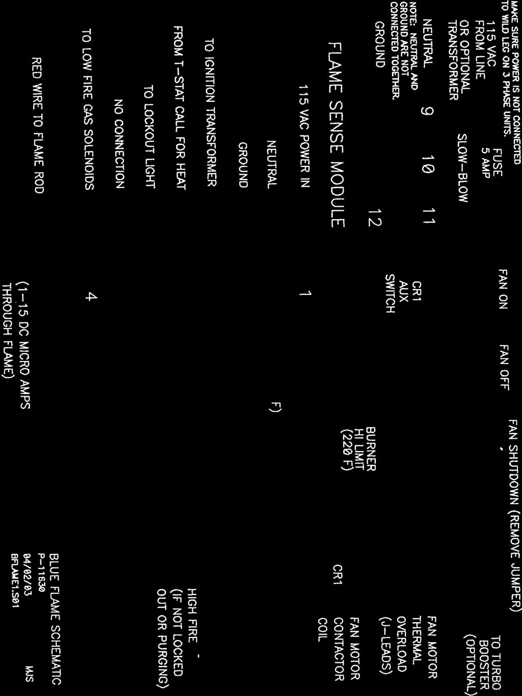
23 CONTROL WIRING Control wiring will be based upon which controlling unit is on the drying bin. The wiring shown here is for a Compudry Command Center. If another controller is used, consult the factory for assistance. In general, the fan(s) should be shutdown whenever a Grain Hi-Limit, Gearbox Hi-Limit, or Compudry Fan Interrupt opens. The burner(s) should shut off whenever a Plenum Hi-Limit, Low Grain Shut-off, or Thermostat opens. All terminal numbers refer to the 12 pole terminal strip, not the 8 pole inverted header that the flame sense module plugs into, unless otherwise noted. The Blue Flame 12 pole terminal strip is a spring cage clamp type. The following diagram shows how to properly connect the wires. Make sure the wire is lined up to go straight into the terminal before pressing on the spring. 1). For fan shutdown, remove the jumper between terminals 6 and 7 and connect a normally closed fan shut down contact in place of the jumper. The jumper between terminals 7 and 8 can also be removed if another fan shutdown circuit is required. 2). Terminal 8 is used to apply power to the turbo booster control circuit, if one is present. 3). Terminals 1, 2, and 3 on this burner are the thermostat connections and have the same function as the corresponding terminals A, B, and C did on previous Blue Flames. Terminal 1 is the thermostat source of power. Terminal 2 is the call for heat or low fire connection. Terminal 3 is the high fire connection. 22
24 CONTROL WIRING TO COMPUDRY COMMAND CENTER See the Compudry Command Center Installation manual for more details. Install control wiring conduit from the Command Center to the Blue Flame. The conduit can go from the Command Center directly to the Blue Flame, or it can go to a junction box on the bin side wall, to pick up the grain hi-limit wires. Each run will require at least 7 control wires and one ground wire. Connect one end of the green ground wire to the grounding terminal strip in the Blue Flame Control Box. Connect the other end of the green ground wire to the grounding terminal strip in bottom right-hand corner of the starter panel in the Command Center. Connect terminals 1,2, and 3, of the Blue Flame 12 pole terminal strip to J3 in the Command Center as shown below. Be sure to install the jumpers as shown for each Blue Flame installed. BLUE FLAME TO COMMAND CENTER THERMOSTAT CONNECTIONS 23
25 CONTROL WIRING TO COMPUDRY COMMAND CENTER, Cont'd: Connect terminals 6 and 7, of the Blue Flame 12 pole terminal strip to J2 in the Command Center as shown below. Connect the two leads from each Grain Hi-Limit to J2 in the Command Center as shown below. Be sure to remove the jumpers as shown for each extra Blue Flame installed. Note that there will be two wires under J2 terminal 8 in the Command Center. BLUE FLAME TO COMMAND CENTER FAN INTERRUPT AND GRAIN HI-LIMIT CONNECTIONS 24
26 INITIAL CHECKOUT 1). Once the wiring is completed, make sure the burner power switch is off. Make sure everyone is out of the grain bin and are safely away from all drying equipment, then unlock the main power. Lock the bin entrances shut, then turn on the main power. Check for proper incoming voltages in the Blue Flame control box. If connected to a Compudry Command Center, make sure the fan(s) enabled light is on. On the Blue Flame, press the fan start switch then quickly press the fan stop switch. If the fan does not attempt to start, make sure there is a separate neutral wire connected to terminal #9. It the fan did attempt to start, check the fan blade for proper rotation. Looking from the back of the fan into the bin, rotation should be counter-clockwise. If the rotation is not correct, and the incoming power is three phase, exchange any two incoming wires. Disconnect and lock out the power first! Make sure that the wild leg does not end up on the control power! Re-apply power. 2). Press the fan start switch. After the fan has reached operating speed, verify that that air is going into the bin, not blowing out. 3). Set the Low Grain Shut-off, or Grain Level Indicator to Bypass, and turn up the thermostat or set the Command Center to call for heat. Leave the fuel shut off for now. 4). Turn on the burner power switch. The burner power light should come on. The High Fire and Lockout lights should also come on. After a 30 second purge, the spark plug should start sparking. The Lockout light should go off for about 5 seconds, then come back on. The burner is now locked out because there wasn't any fuel to burn. 5) Shut the burner power switch off and turn on the fuel supply. Turn the burner power switch back on. After 30 seconds the burner should fire. On LP units adjust the vaporizer and regulator as required. If the burner does not continue to run, inspect the flame rod to make sure it hasn't gotten out of adjustment during shipping. It should be in the burner vee, immersed in the flame, but not touching metal. 6). If possible, adjust the thermostat or Command Center to cycle the burner to low fire and off, then back on. 7). Shut off the fuel supply and allow the lines to burn out. Once the flame is gone, the burner should go into lockout. 8). Disconnect and lock out the main power. 25
27 OPERATING INSTRUCTIONS To Operate: The fan must be running to provide power to the burner. The fuel supply must be turned on. The Low Grain Shut Off or Grain Level Indicator must be enabled (either in the Auto or Bypass position). The plenum thermostat or Compudry must be set above ambient temperature and be calling for heat. On LP units, the regulator should initially be set less than ½ way between full on (all the way in) and full off (all the way out). Turn the vaporizer turnbuckle to move the vaporizer out about 12" away from the bottom of the burner vee as a starting point. On Natural Gas units, open the ball valve about ¼ turn. 1). Turn on the Burner Power Switch. The Burner Power, High Heat, and Lockout lights should all come on. 2). After a 30 second purge, the ignition transformer will come on, then the gas valves will open. 3). The burner should fire within 5 seconds, then shut off the ignition transformer. 4). On LP units, adjust the vaporizer in or out, by rotating the turnbuckle, so the gas line before the regulator is warm, not hot, to touch. CAUTION: The vaporizer line can become scalding hot if set too close to the flame. The pipe train can freeze up if the vaporizer is too far away from the flame. Keep checking the vaporizer as it will require several minutes for the temperature to stabilize. 5). Adjust fuel pressure so the burner cycles between High Fire and Low Fire. If burner cycles off, reduce gas pressure. If burner stays on High Fire, increase gas pressure. On LP units, fuel pressure is adjusted with the pressure regulator. On Natural Gas units, fuel pressure is adjusted with the pressure regulating ball valve. Re-adjust vaporizer as required for LP units. 6). If the Lockout light is on for more than 30 seconds, reset the control by turning the burner switch off for a few seconds, then back on. 26
28 BLUE FLAME OPERATOR'S CONTROL PANEL 27
29 Operating Instructions cont'd: Short Term Stop (less than a couple days): 1). Close manual gas valve at Blue Flame. 2). Burn out all gas in pipe train. 3). Turn burner switch off. 4). Let burner cool down for a few minutes then stop fan. Long Term Stop (more than a couple days): 1). Close gas valve at storage tank. 2). Burn out all gas in line. This may take a while on LP units. 3). Turn burner switch off. 4). Let burner cool down for a few minutes then stop fan. MAINTENANCE Disconnect and lock out all power before opening any control boxes or removing any shields. Make sure everyone is clear of all drying equipment before restoring power. 1). Once every month, start the fan to circulate the grease in the motor bearings. In the off season, do not allow the fan blades on single phase units to free wheel with the wind. It can wear a groove in the centrifugal start switch. Follow motor manufacturer's recommendations for relubricating motor bearings. 2). Prior to each drying season, make sure the fan blade rotates freely. Make sure the blade is not coated by any foreign material which could unbalance it or block airflow. If blade requires cleaning, make sure power is disconnected and locked out first! 28
30 Maintenance cont'd: 3). On LP units, yearly remove the wire screen in the gas strainer and clean it. The big plug at the bottom of the strainer must be removed to get at the screen. Make sure the fuel supply is shut off first! 4). Yearly, check all wiring and gas connections to be sure they are tight and in good condition. A mixture of one part soap to three parts water can be brushed onto pressurized gas line connections to check for leaks. Check all flexible hoses for wear or cracks and replace if necessary. 5). Yearly, inspect the burner element for cracks and plugged holes. Check for an even burn when operating. On LP units, check the vaporizer tube for wear and replace if splits or cracks appear. 6). Maintain a clean operation. Clean up spilled corn, clean out fines under the bin floor (contact Shivvers about clean-out doors), keep all control boxes shut and replace seals if required. Control the rodent population. Control weeds and tall grasses around the Blue Flame. They can get sucked in and block airflow or start a fire. They can interfere with damper operation. 7). At the beginning of each season, check for proper operation of the flame lockout system. With the burner running, shut off the fuel supply. Approximately 6 seconds after the flame goes out, the Lockout light on the front panel should come on and stay on. Make sure it stays on for more than 30 seconds. It is not safe to operate the burner without this circuit operating properly. 8). During the drying season, check the transition dampers for free movement and proper operation. 9). At the end of the season, make sure the main power is disconnected and locked off. There will be fewer problems with lightning damage with all switches and breakers open. 10). The flame rod may corrode and will not conduct enough current, especially when hot. A cleaning before the season may be required. Disconnect and lock out power. Open Blue Flame control box. Remove red wire from top of flame rod. Remove two screws from flame rod plate. Remove flame rod and plate, being careful not to change the rotational angle of the flame rod to the plate. Clean the flame rod with emery cloth and carefully re-insert it. Reconnect the red wire. Shut the control box. 29
31 TROUBLESHOOTING Disconnect and lock out all power before opening any control boxes or removing any shields. Make sure everyone is clear of all drying equipment before restoring power. Only qualified personnel should perform troubleshooting on energized circuits. All terminal strip numbers refer to the 12 pole terminal strip in the Blue Flame control box unless otherwise noted. FAN WILL NOT START 1). Make sure main power is turned on. Make sure the fan(s) are enabled at the Compudry Command Center or Grain Hi-Limit Control box. If the gearbox hi-limit or any grain hi-limit is open, the fan(s) will not start until the hi-limits cool down. This may take quite a while. If these switches are opening, make sure the problem is identified and corrected or a fire may result. Monitor the system closely. 2). If fan will not start after initial wiring, make sure separate neutral wire is in conduit and connected to terminal #9. 3). Check 5 amp slow blow fuse. 4). Check for power on terminal #6 with fan start switch held down. If no power, could be bad start switch or stop switch. 5). If there is power on terminal #6 with fan start switch held down, check on terminal #7. If no power on #7, fan shutdown device is not turned on, or is defective. 6). If there is power on terminal #7 with fan start switch held down, check on terminal #8. If there is power on #8, check for power at the black wire on the Fan Motor Contactor Coil. If there isn't any power at the coil, the Fan Motor thermal switch (J-leads) are open. If motor isn't hot, the motor thermal switch may be defective. 7). If there is power on terminal #9 when the fan start switch is held down, there is an open neutral. See step #2. 8). If there is power at the black wire on the fan motor contactor coil, and not at the white neutral wire on the contactor coil, when holding down the fan start switch, then the coil is open and will need to be replaced. 30
32 Troubleshooting cont'd: FAN WILL RUN ONLY WHILE START SWITCH IS HELD DOWN (stops when start switch is released) 1). Defective (open) auxiliary switch on contactor. FAN WILL STOP ONLY WHILE STOP SWITCH IS HELD DOWN (starts back up when stop switch is released) 1). Defective (shorted) auxiliary switch on contactor. 2). Defective (shorted) fan start switch. BURNER POWER LIGHT WILL NOT COME ON 1). Fan must be running. Make sure burner power switch is on. 2). Burner Hi-Limit may be open. Shut power off and lock it out. Open control box and press manual reset on Burner Hi-Limit. 3). On L.P. units, Vaporizer Hi-limit may be open. Press manual reset with insulated screwdriver. Check vaporizer for proper setting. It may be getting too hot (140 F). Check L.P. supply tank. It may be low and supplying vapor instead of liquid to the burner. This would cause vaporizer to get too hot. If outside temperature is below 20 F, tank may not develop enough pressure to supply only liquid. A vapor return line may need to be added. 4). Check for power on terminal #1. If power is there, burner power light may be defective. LOCKOUT LIGHT WILL NOT COME ON (Burner power light is on) 1). There is not a call for heat. Make sure plenum temperature controlling device is calling for heat (power on terminal #2). The target temperature may be set too low. The low grain shut off or grain level indicator may not be enabled. The plenum hi-limit may be open. 2). Lockout light or flame sense module may be defective. 31
33 Troubleshooting cont'd: LOCKOUT LIGHT WILL NOT GO OFF 1). After power is applied, the lockout light should be on for 30 seconds during the purge cycle. It should then go off for at least 5 seconds for an ignition trial. If it doesn't go off at all, the flame sense module may be defective. BURNER WILL NOT SPARK BUT GAS COMES ON (View spark plug through inspection window) 1). After the 30 second purge delay, power should be applied to terminal #4 of the flame sense module 8 pole terminal strip. If there isn't power here for at least 5 seconds (after the 30 second purge delay), the flame sense module may be defective. 2). If step #1 is OK, the ignition transformer could be defective. Make sure the ignition transformer is bolted securely to the control box. 3). Could be a bad spark plug, or grounding electrode. Too large of a gap for the spark to jump across. 4). Could be a bad ignition cable. It could be open, or shorting out to ground somewhere. Check where cable comes through inside cylinder weldment. BURNER SPARKS BUT WILL NOT FIRE (Not even for 5 seconds) 1). If there isn't any pressure indication on the gauge, make sure fuel supply is turned on. On L.P. units, regulator must be screwed in at least partially. 2). If there isn't any pressure indication on the gauge, it could be a defective liquid or low fire solenoid. If there isn't any power on terminal #4, it could be a defective flame sense module. The power will only be on terminal #4 for about 5 seconds while the burner is sparking during the trial for ignition. 3). If there is a pressure indication on the gauge, then there is a problem with the fuel/air mix at the ignition point (spark plug). Try changing fuel pressure. If the bin is too empty or too full, it could be affecting the airflow. Make sure the burner element is in good condition (no pieces missing, clogged fuel holes, etc.). 32
34 Troubleshooting cont'd: BURNER FIRES FOR 5 SECONDS, BUT WON'T RUN CONTINUOUSLY (Most of these problems deal with the flame sensing rod) 1). Make sure the flame rod is immersed in the flame. The flame rod can be bent into any shape, but should be heated first to prevent breakage. The flame rod can also be rotated in its ceramic by loosening the top connector and brass nut. 2). Make sure the flame rod is not touching any metal. The flame rod and/or burner element can move while operating due to the heat. Watch through the inspection window. 3). The flame rod may be corroded and not conducting enough current, especially when hot. Disconnect and lock out power. Open Blue Flame control box. Remove red wire from top of flame rod. Remove two screws from flame rod plate. Remove flame rod and plate, being careful not to change the rotational angle of the flame rod to the plate. Clean the flame rod with emery cloth and carefully re-insert it. Reconnect the red wire. Shut the control box and try again. 4). If possible, measure the flame current with a D.C. micro-ammeter placed in series with the red flame sense wire. Flame sense current should be from 1 to 15 DC micro-amps. 5). If flame rod does not seem to be the problem, the flame sense module may be defective. PIPE TRAIN FREEZES UP ON L.P. UNITS 1). Usually the frost will start near where the problem is. 2). If the incoming line is frosted, make sure tank has fuel. Make sure the excess flow valve on tank hasn't shut. To reset, shut tank valve off, then turn back on slowly. 3). If frost starts at upper pipe train, make sure vaporizer is adjusted properly. If it is, there could be a problem with the pressure regulator or low fire solenoid. They can get sticky oil in them from the liquid propane, and will require cleaning or replacement. 33

35
BLUE FLAME II MAXX BURNER FOR DOUBLE WIDTH, DOUBLE INLET CENTRIFUGAL FANS
 BLUE FLAME II MAXX BURNER FOR DOUBLE WIDTH, DOUBLE INLET CENTRIFUGAL FANS Installation & Operating Instructions For Models: 691A-001A -- LP 691B-001A -- NG Shivvers Manufacturing, Inc. 614 West English
AXIAL HEATER TROUBLE SHOOTING GUIDE. Models: AX24 N/PV, AX24 N/PV LT, AX24 LP AX26 N/PV, AX26 N/PV LT, AX26 LP AX28 N/PV, AX28 N/PV NT, AX28 LP
 AXIAL HEATER TROUBLE SHOOTING GUIDE Page 1 July 2009 Table of Contents Frequently Asked Questions... 3 Axial Heater CONTROL (Siemens LME69) Troubleshooting Chart... 4 Axial Heater BURNER Troubleshooting
1 and 2 Fan Vision Series Portable Dryers
 1 and 2 Fan Vision Series Portable Dryers Operator s Manual PNEG-1456 Date: 09-29-09 PNEG-1456 2 PNEG-1456 1 and 2 Fan Vision Series Portable Dryers Table of Contents Contents Chapter 1 Safety... 5 Safety
AXIAL HEATER - CSA INSTALLATION & OPERATINGMANUAL. P/N Rev 0 NATURAL GAS LIQUID PROPANE VAPOR PROPANE
 AXIAL HEATER - CSA INSTALLATION & P/N 782014 Rev 0 NATURAL GAS LIQUID PROPANE VAPOR PROPANE CH18T-NGE CH18T-VPGE CH24T-NGEM CH24T-LPGE / LPGEM CH24T-VPGE CH28T-NGEM CH28T-LPGE / LPGEM CH28T-VPGE OPERATINGMANUAL
No. Of Ignition Trials: No. Of Re-Ignition Attempts. Reset by interrupting power for 5.0 Seconds. Diagnostic Output. Re-Ignition Limit Exceeded
 DS1-Q INSTALLATION INSTRUCTIONS General Description Model DS1-Q is used to replace and eliminate the factory installed slow responding glow-bar igniter, sensor and associated wiring in commercial laundry
Internet Version for Reference Only INDUCED DRAFT COMMERCIAL WATER HEATERS SUPPLEMENT INSTRUCTIONS TO PART #
 INDUCED DRAFT COMMERCIAL WATER HEATERS SUPPLEMENT INSTRUCTIONS TO PART #238-39387-00 THIS INSTRUCTION SUPPLEMENT IS ONLY INTENDED TO GIVE INSTALLATION INSTRUCTIONS AND INFORMATION RELATED TO THE INDUCED
The Danger signal indicates an immediately hazardous situation which, if not avoided, will result in death or serious injury.
 The Danger signal indicates an immediately hazardous situation which, if not avoided, will result in death or serious injury. The Warning signal alerts you to potential hazards or unsafe practices which,
J120 STEAM BOOSTER INSTALLATION, OPERATION, AND SERVICE MANUAL J120 STEAM BOOSTER. J120 Steam Booster Manual D
 INSTALLATION, OPERATION, AND SERVICE MANUAL J120 STEAM BOOSTER J120 STEAM BOOSTER J120 Steam Booster Manual REVISION HISTORY Revision Letter Revision Date Made by Applicable ECNs Details A 10-27-04 CBW
CALDWELL HEATER INSTALLATION AND OPERATION MANUAL
 CALDWELL HEATER INSTALLATION AND OPERATION MANUAL THIS MANUAL IS FOR THE INSTALLATION, OPERATION AND MAINTENANCE OF HEATER MODELS #H33-NGE-PE, #H33-LPGE, #H28-NGE-PE, #H28-LPGE, #H28-LT-NGE-PE, #H24-NGE-PE,
Volume MATHEWS COMPANY. Legacy Series L1250 /L1350 /L2550 /L2650 /L2700 /L3100 /L3105 /L4145 /L5175. Operations Manual
 Volume 1 MATHEWS COMPANY Legacy Series L1250 /L1350 /L2550 /L2650 /L2700 /L3100 /L3105 /L4145 /L5175 2011 Mathews Company 500 Industrial Avenue Crystal Lake, IL 60012 USA Toll Free Number: (800) 323 7045
CALDWELL HEATER INSTALLATION AND OPERATION MANUAL
 CALDWELL HEATER INSTALLATION AND OPERATION MANUAL THIS MANUAL IS FOR THE INSTALLATION, OPERATION AND MAINTENANCE OF HEATER MODELS #H33-NGE-PE, #H33-LPGE, #H28-NGE-PE, #H28-LPGE, #H28-LT-NGE-PE, #H24-NGE-PE,
Drying Tumblers. Troubleshooting. 120 Pound Capacity 170 Pound Capacity. Refer to Page 5 for Model Numbers. Part No August 2007
 HIGH LOAD READY MEDIUM TEMPERATURE LOW LOW AIR FLOW NON REV REV PUSH TO START 10 5 15 0 50 40 60 0 30 10 20 Drying Tumblers 120 Pound Capacity 170 Pound Capacity Page 5 for Model Numbers Troubleshooting
2 & 3 Module DriTek Plus Dryers
 OPERATOR S MANUAL 2 & 3 Module DriTek Plus Dryers Division of ffi Corporation 1004 E. Illinois St. Assumption, IL 62510 PNEG-1540 Date: 09-15-2006 PNEG-1540 CONTENTS INTRODUCTION...4 OPERATING PRECAUTIONS...4
L A signature series TA T N E RE O, A L L A T S IN
 signature series COMMERCIAL STEAM GENERATORS INSTALLATION, OPERATION AND MAINTENANCE MANUAL INSTALLATION MANUAL COMMERCIAL STEAM GENERATOR SIGNATURE SERIES (SS) INTRODUCTION Steam Sauna manufactures steam
KEES, INC. Installation & Maintenance Manual DFG Series Direct Gas Fired Make-up Air Heaters. Table of Contents FOR YOUR SAFETY.
 KEES, INC. Installation & Maintenance Manual DFG Series Direct Gas Fired Make-up Air Heaters Table of Contents FOR YOUR SAFETY Page # Topic If you smell gas: 1 Description of Operation 1 Receiving the
Portable Dryer Touch Screen Controls
 Portable Dryer Touch Screen Controls and Reference Manual PNEG 1509 PNEG 1509 Date: 1 23 08 Reference Table of Contents TABLE OF CONTENTS DRYER SAFETY & DRYER INFORMATION...4 SPECIAL SETUP SCREENS...5
OPERATING INSTRUCTIONS MANUAL (Please retain for future reference) FVN/P-400 INDIRECT FIRED SPACE HEATERS
 FVN/P-400 INDIRECT FIRED SPACE HEATERS") OPERATING INSTRUCTIONS MANUAL (Please retain for future reference) For FVN/P-400 INDIRECT FIRED SPACE HEATERS CERTIFIED FOR USE IN CANADA AND U.S.A. As per Standard ANSI Z83.7/CSA 21.4 2000 Gas Fired Construction
OPERATING INSTRUCTIONS MANUAL (Please retain for future reference) For FVN/P-400 INDIRECT FIRED SPACE HEATERS CERTIFIED FOR USE IN CANADA AND U.S.A. As per Standard ANSI Z83.7/CSA 21.4 2000 Gas Fired Construction
Deluxe Vane Axial Heater
 Deluxe Vane Axial Heater MODEL # VH - - - D (HIGH FIRE) MODEL # VL - - - D (LOW FIRE) Owner's Manual MANUAL # PNEG-86 VANE AXIAL HEATER CHECK LIST Deluxe Vane Axial Heater!OK. All wire connections. Spark
Single-Module Portable Dryer
 Single-Module Portable Dryer Models: 1100, 1200, 1200S CFAB-1 FAN, CFAB- 2 FAN, C2100A Installation Guide PNEG-1891 Version 3.1 Date: 09-09-16 PNEG-1891 All information, illustrations, photos, and specifications
MASTER JOCKEY PUMP CONTROLLER. Model JPCE INSTRUCTION MANUAL. C 2018 Master Control Systems, Inc
 MASTER JOCKEY PUMP CONTROLLER Model JPCE INSTRUCTION MANUAL C 2018 Master Control Systems, Inc TABLE OF CONTENTS Important Safety Information. Page 3 General Description and Installation.. Page 4 Model
OWNER S MANUAL Manufactured Home Downflow Gas Furnace: MGD-B Series
 OWNER S MANUAL Manufactured Home Downflow Gas Furnace: MGD-B Series Heat Controller, Inc. 1900 Wellworth Ave. Jackson, MI 49203 (517)787-2100 www.heatcontroller.com Owner s Manual MGD-B SERIES GAS FURNACE
OPERATIONS AND MAINTENANCE MANUAL FOR THE 8-TON TURF CART ENVIRONMENTAL CONTROL UNIT (ECU) PART NUMBER
 PART NUMBER") OPERATIONS AND MAINTENANCE MANUAL FOR THE 8-TON TURF CART ENVIRONMENTAL CONTROL UNIT (ECU) PART NUMBER 2001927 Prepared by: 860 Douglas Way PO Box 530 Natural Bridge Station, VA 24579 1 1.0 SCOPE: This
OPERATIONS AND MAINTENANCE MANUAL FOR THE 8-TON TURF CART ENVIRONMENTAL CONTROL UNIT (ECU) PART NUMBER 2001927 Prepared by: 860 Douglas Way PO Box 530 Natural Bridge Station, VA 24579 1 1.0 SCOPE: This
Service Manual Model 3163
 Service Manual Model 3163 Contents Important Safety Information.......... 1 Specifications.................. 2 General Information.............. 2 Direct Vent Requirements........... 2 Propane System................
Competitor Series Dryers
 Cost Efficient, Competitively Priced, Completely GSI. Competitor Series Dryers "Your Complete Systems Manufacturer." THE COMPETITIVE EDGE GSI Competitor 100 Series grain dryers offer all the latest technological
Installation Instructions
 50ES--A, 50EZ--A, 50VG--A, B, 50VL--A, B, 50VR--A, 50VT--A, B 604D-- --A, 607C-- --A, B, 607E-- --A, 704D-- --A, 707C-- --A, B, 707E-- --A PA3G -- -- A, PH3G -- -- A, PA4G, PH4G PAD3, PHD3, PAD4, PHD4,
Ultra Speed Burnisher 120V & 240V with NEMA Plug
 Ultra Speed Burnisher 120V & 240V with NEMA Plug Operator's Manual Manual del operador Manuel de l utilisateur READ THIS BOOK LEA ESTE MANUAL LISEZ CE MANUEL ES FR English (2-12) Español (14-24) Français
Equipment Alert. P-Trap Must Be Installed to Exhaust or Warranty will be Voided. Refer to this Manual for installation Instructions
 Dry Assembled Elbows MUST Glue when Installed Exhaust Connection P-Trap Must Be Installed to Exhaust or Warranty will be Voided AA2360 Refer to this Manual for installation Instructions 2011 Midmark Corp.
SERVICE FACTS WARNING M801-SF-1C. Gas Furnaces Upflow & Downflow Induced Draft 1 Stage Heat Models: DISCONNECT POWER BEFORE SERVICING M801P040AU24AA
 SERVICE FACTS Gas Furnaces Upflow & Downflow Induced Draft Stage Heat Models: M80P00AU2AA M80P060AU2AA M80P060AU36AA M80P080BU36AA M80P080BU8AA M80P00BU36AA M80P00CU8AA M80P00CU60AA M80PDU60AA M80P0DU60AA
USER S, MAINTENANCE and SERVICE INFORMATION MANUAL
 CONTENTS SAFETY INFORMATION................ 2 FOR YOUR SAFETY....................... 2 SYSTEM OPERATION.................. 2 THERMOSTATS.......................... 2 INTERMITTENT IGNITION DEVICE...........
PrecisionTemp Shower-Mate
 Shower-Mate Instantaneous Gas Water Heater Installation and Operating Instructions The Shower-Mate is a power vented automatic instantaneous water heater designed to be installed in ventilated marine applications.
Heat Pump Water Heater. Table of Contents
 Table of Contents INTRODUCTION... 3 SAFETY... 3 Electrical... 3 R410a Refrigerant... 3 Scalding... 3 Flammable Vapors... 3 COMPONENT PARTS OF THE HEAT PUMP WATER HEATER... 4 TOOLS... 10 OPERATIONAL MODES...
Humidistat-Thermostat
 Humidistat-Thermostat Model # HF _- - - Owner s Manual PNEG-236 Date: 12-02-09 PNEG-236 2 PNEG-236 Humidistat-Thermostat Table of Contents Contents Chapter 1 Safety... 4 Safety Guidelines... 4 Humidistat-Thermostat
INTRODUCTION THIS MANUAL INCLUDES IMPORTANT SAFETY INFORMATION
 INSTALLATION AND OPERATING INSTRUCTIONS FOR THE HARDY Fuel Oil Furnace Models D-140 & D-350 HARDY MANUFACTURING COMPANY, INC. 12345 ROAD 505 PHILADELPHIA, MS 39350 PHONE: (601) 656-5866 FAX: (601) 656-4559
10.1 Troubleshooting Condition Table
 10.1 Troubleshooting Condition Table Behavior 01. The furnace does not operate when you set the wall thermostat to a high temperature. Component 1. Wall T-Stat (See Section 10.3) 2. Blower/Fan Limit (See
Installation Instructions
 Installation Instructions Blower Packages For Gas Furnaces KCBBA00TG KCBBA00TG NOTE: Read the entire instruction manual before starting the installation. INTRODUCTION When upgrading a Coleman, Intertherm,
OPERATING INSTRUCTIONS MANUAL (Please retain for future reference) F-400T DUAL FUEL CONSTRUCTION HEATER
 F-400T DUAL FUEL CONSTRUCTION HEATER") OPERATING INSTRUCTIONS MANUAL (Please retain for future reference) For F-400T DUAL FUEL CONSTRUCTION HEATER CERTIFIED FOR USE IN CANADA AND U.S.A. As per Standard ANSI Z83.7 2000/ CSA 2.14 2000 Gas Fired
OPERATING INSTRUCTIONS MANUAL (Please retain for future reference) For F-400T DUAL FUEL CONSTRUCTION HEATER CERTIFIED FOR USE IN CANADA AND U.S.A. As per Standard ANSI Z83.7 2000/ CSA 2.14 2000 Gas Fired
HALLMARK INDUSTRIES INC. HALLMARK INDUSTRIES INC. Safety WARNING WARNING. Must reset the voltage! Shallow Well Jet Pumps
 Safety Important Safety Instructions SAVE THESE INSTRUCTIONS - This manual contains important instructions that should be followed during installation, operation, and maintenance of the product. Save this
SERVICE AND INSTALLATION MANUAL MODELS HDO(H) OIL FOR YOUR SAFETY
 OIL FOR YOUR SAFETY") Bousquet Technologies Inc. 2121, Nobel, Ste Julie, Quebec, Canada, J3E1Z9 SERVICE AND INSTALLATION MANUAL MODELS HDO(H) OIL Oil-Fired air heater for industrial and commercial use. FOR YOUR SAFETY Do not
Bousquet Technologies Inc. 2121, Nobel, Ste Julie, Quebec, Canada, J3E1Z9 SERVICE AND INSTALLATION MANUAL MODELS HDO(H) OIL Oil-Fired air heater for industrial and commercial use. FOR YOUR SAFETY Do not
MASTER PRESSRE MAINTANENCE CONTROLLER. Models PMCE INSTRUCTION MANUAL. C 2018 Master Control Systems, Inc
 MASTER PRESSRE MAINTANENCE CONTROLLER Models PMCE INSTRUCTION MANUAL C 2018 Master Control Systems, Inc TABLE OF CONTENTS Important Safety Information. Page 3 General Description and Installation.. Page
FIREYE M4RT1 FLAME SAFEGUARD CONTROLS DESCRIPTION
 M-4000 JANUARY 29, 200 FIREYE M4RT1 FLAME SAFEGUARD CONTROLS WARNING: Selection of this control for a particular application should be made by a competent professional, licensed by a state or other government
Use & Care Manual. Electric Tankless Water Heaters. With Installation Instructions for the Installer AP15447 (10/10)
") Use & Care Manual With Installation Instructions for the Installer Electric Tankless Water Heaters The purpose of this manual is twofold: one, to provide the installer with the basic directions and recommendations
Use & Care Manual With Installation Instructions for the Installer Electric Tankless Water Heaters The purpose of this manual is twofold: one, to provide the installer with the basic directions and recommendations
AquaSaver DISPOSER CONTROL CENTER Installation Manual. Model AS-101K
 AquaSaver DISPOSER CONTROL CENTER Installation Manual Model AS-1K The Danger signal indicates an immediately hazardous situation which, if not avoided, will result in death or serious injury. The Warning
ENVIRONMENTAL CONTROL UNIT (ECU) PART NUMBER OPERATIONS AND MAINTENANCE MANUAL
 PART NUMBER OPERATIONS AND MAINTENANCE MANUAL") ENVIRONMENTAL CONTROL UNIT (ECU) PART NUMBER 2001829 OPERATIONS AND MAINTENANCE MANUAL Prepared by: 860 Douglas Way PO Box 530 Natural Bridge Station, VA 24579 1.0 SCOPE: This Operations and Maintenance
ENVIRONMENTAL CONTROL UNIT (ECU) PART NUMBER 2001829 OPERATIONS AND MAINTENANCE MANUAL Prepared by: 860 Douglas Way PO Box 530 Natural Bridge Station, VA 24579 1.0 SCOPE: This Operations and Maintenance
Operator: Save these instructions for future use!
 WHITE-RODGERS 50A55-474 & 50A55-571 Integrated Furnace Controls INSTALLATION INSTRUCTIONS Operator: Save these instructions for future use! FAILURE TO READ AND FOLLOW ALL INSTRUCTIONS CAREFULLY BEFORE
TRI-PLATE B INSTALLATION, OPERATION, AND MAINTENANCE INSTRUCTIONS PART NO EFFECTIVE MARCH 1, 1983 REPRINT APRIL 16, 1999
 TRI-PLATE B INSTALLATION, OPERATION, AND MAINTENANCE INSTRUCTIONS PART NO. 8801469 EFFECTIVE MARCH 1, 1983 REPRINT APRIL 16, 1999 THE MILK COOLING SYSTEMS SPECIALISTS TM FRE-HEATER Part No. 8801469 Table
WHEN TROUBLESHOOTING, PERFORM THE STEPS IN ORDER.
 WHEN, PERFORM THE STEPS IN ORDER. BURNER WON T LIGHT Control System 1. Is the main interlock in auto? The burner will not light if the dryer is in manual mode b. No: Switch the main interlock to auto 2.
BGH Series Hot Surface Ignition Control
 Installation Instructions BGH Series Issue Date April 14, 2011 BGH Series Hot Surface Ignition Control Application The BASO Gas Products BGH Series Hot Surface Ignition (HSI) control is microprocessor
Service Manual For model N260 - a 2.4 cu. ft., 2-way refrigerator. For model N a 2.4 cu. ft., 3-way refrigerator.
 Service Manual For model N260 - a 2.4 cu. ft., 2-way refrigerator. For model N260.3 - a 2.4 cu. ft., 3-way refrigerator. NORCOLD, Inc. P.O. Box 4248 Sidney, OH 45365-4248 Part No. 619260A (4-98) Table
Installation Requirements for Models:
 900 & 9100 Series Refrigerators Installation Requirements for Models: 9162 9163 9182 9183 962 963 982 983 WARNING Improper installation, adjustment, alteration, service, or maintenance can cause injury
Installation Instructions Dual Fuel Ranges
 Installation Instructions Dual Fuel Ranges E30DF74EPS E36DF76EPS E48DF76EPS 5995447082 2 Safety IMPORTANT SAFETY INSTRUCTIONS Safety Precautions Do not attempt to install or operate your unit until you
OPERATING INSTRUCTIONS MANUAL (Please retain for future reference) F-1500T DUAL FUEL CONSTRUCTION HEATER
 F-1500T DUAL FUEL CONSTRUCTION HEATER") OPERATING INSTRUCTIONS MANUAL (Please retain for future reference) For F-1500T DUAL FUEL CONSTRUCTION HEATER CERTIFIED FOR USE IN CANADA AND U.S.A. As per Standard ANSI Z83.7 2000/ CSA 2.14 2000 Gas Fired
OPERATING INSTRUCTIONS MANUAL (Please retain for future reference) For F-1500T DUAL FUEL CONSTRUCTION HEATER CERTIFIED FOR USE IN CANADA AND U.S.A. As per Standard ANSI Z83.7 2000/ CSA 2.14 2000 Gas Fired
SERVICE MANUAL VC3ED FULL SIZE ELECTRIC CONVECTION OVEN - NOTICE -
 SERVICE MANUAL VC3ED FULL SIZE ELECTRIC CONVECTION OVEN VC3ED ML-137013 - NOTICE - This Manual is prepared for the use of trained Vulcan Service Technicians and should not be used by those not properly
Competitor Series Dryers
 Cost Efficient, Competitively Priced, Completely GSI. Competitor Series Dryers "Your Complete Systems Manufacturer." THE COMPETITIVE EDGE GSI Competitor 100 Series grain dryers offer all the latest technological
Circulating Oil Temperature Control System
 Installation & Operation Manual Circulating Oil Temperature Control System i PQ451 161-123417-037 February 2019 Table of Contents Contents Page Number Section 1 Getting Started... 1 Section 2 Installation...
MODEL MW200 MODEL MW600 AIR DRYER
 OPERATING MANUAL MODEL MW200 MODEL MW600 AIR DRYER Mail Address: 226A Commerce St. Tel: 303-465-3063 Broomfield, CO 80020 Fax: 303-465-9294 TABLE OF CONTENTS 1.0 GENERAL...3 2.0 SPECIFICATIONS...3 3.0
Installation Manual CARBONATOR With Plain-Water Booster
 CORNELIUS INC One Cornelius Place Anoka, MN 55303-6234 Telephone (800) 238-3600 Facsimile (763) 422-3246 Installation Manual CARBONATOR With Plain-Water Booster IMPORTANT: It is the responsibility of the
Panel Fan Series Operators Manual (Galvanized and Polymer)
") Panel Fan Series Operators Manual (Galvanized and Polymer) Galvanized Panel Fan with Three Wing Blade IMPORTANT: READ AND SAVE THESE INSTRUCTIONS Read all instructions carefully before attempting to assemble,
Panel Fan Series Operators Manual (Galvanized and Polymer) Galvanized Panel Fan with Three Wing Blade IMPORTANT: READ AND SAVE THESE INSTRUCTIONS Read all instructions carefully before attempting to assemble,
INSTALLATION INSTRUCTIONS FOR 8330*5511 MOUNTING KIT
 RV Products Division INSTALLATION INSTRUCTIONS FOR 8330*5511 MOUNTING KIT 8330-752 CONTROL BOX KIT (12 VDC COOL ONLY) 9330A755 CONTROL BOX KIT (12 VDC HEAT/COOL) 8530-750 CONTROL BOX KIT (24 VAC COOL ONLY)
OPERATORS MANUAL FOR Mi-T-M CORONA DISCHARGE OZONE GENERATORS
 OPERATORS MANUAL FOR Mi-T-M CORONA DISCHARGE OZONE GENERATORS CAUTION RISK OF INJURY! READ MANUAL BEFORE OPERATING! This manual is an important part of the Corona Discharge Ozone Generator and must remain
Condensing Unit Installation and Operating Instructions
 Bulletin WCU_O&I 01 June 2003 Condensing Unit Installation and Operating Instructions WCU Air Cooled Condensing Unit Table of Contents Section 1. Section 2. Section 3. Section 4. Section 5. Section 6.
Northwest RV Supply Manual Compliments of Printed From 900 & 9100 Series
 900 & 9100 Series Service Manual & Parts List for Models 9182 9183 9162 9163 982 983 962 963 Safety Information............... 1 Introduction................... 2 Specifications.................. 3 Operating
prestige Condensing Water Boiler SERVICE TECHNICIAN S TROUBLE SHOOTING GUIDE TSG-SOLO-9/04
 prestige Condensing Water Boiler SERVICE TECHNICIAN S TROUBLE SHOOTING GUIDE 2004-28 TSG-SOLO-9/04 Table of Contents INTRODUCTION Page 1 SERVICING TIPS AND INSTRUCTIONS Page 3 CONTROL MODULE DISPLAY -
Indirect gas-fired air heater
 Indirect gas-fired air heater SERIES HD INSTALLATION AND SERVICE MANUAL MANUFACTURED BY : BROTHERS LIMITED WARNING Improper installation, modification, adjustment or maintenance may cause damage, injury
95M-200. Gas-Fired Direct Vent Modulating Hot Water Boiler. Control Manual And Troubleshooting Guide. P/N , Rev.
 95M-200 Gas-Fired Direct Vent Modulating Hot Water Boiler Control Manual And Troubleshooting Guide P/N 24000604, Rev. C [04/09] WARNING! Revise boiler control parameters only if you fully understand the
southbend A MIDDLEBY COMPANY INSTALLATION AND OPERATION MANUAL CG214 (E) CG314 (E) CG414 (E) CG220 (E) CG320 (E) CG325 (E) GAS BOILERS MODELS:
 CG314 (E) CG414 (E) CG220 (E) CG320 (E) CG325 (E) GAS BOILERS MODELS:") INSTALLATION AND OPERATION MANUAL GAS BOILERS MODELS: CG214 (E) CG314 (E) CG414 (E) CG220 (E) CG320 (E) CG325 (E) southbend A MIDDLEBY COMPANY 1100 Old Honeycutt Road Fuquay-Varina, NC 27526 (919) 552-9161
INSTALLATION AND OPERATION MANUAL GAS BOILERS MODELS: CG214 (E) CG314 (E) CG414 (E) CG220 (E) CG320 (E) CG325 (E) southbend A MIDDLEBY COMPANY 1100 Old Honeycutt Road Fuquay-Varina, NC 27526 (919) 552-9161
Operator: Save these instructions for future use!
 WHITE-RODGERS 50A55-286 Integrated Furnace Control INSTALLATION INSTRUCTIONS Operator: Save these instructions for future use FAILURE TO READ AND FOLLOW ALL INSTRUCTIONS CAREFULLY BEFORE INSTALLING OR
WD7664 / WD7663 Maxon Burner Ellis Whisper Dryer Installation & Start UP
 WD7664 / WD7663 Maxon Burner Ellis Whisper Dryer Installation & Start UP Receiving Do a quick visual inspection on the truck for any major damage prior to signing the paperwork. Damage should be noted
P4200PM / P5000PM Remote Air Dryer User s Guide
 P4200PM / P5000PM Remote Air Dryer User s Guide 1. Welcome & Congratulations Congratulations on your purchase of a new PUREGAS P4200PM / P5000PM Air Dryer! We here at PUREGAS are very proud of our products
Freightliner Refrigerator Troubleshooting Guide For (TJ18F) (TJ22F) (TJ18FP3)
 (TJ22F) (TJ18FP3)") www.dometic.com Freightliner Refrigerator Troubleshooting Guide For Before initiating troubleshooting, the following equipment is recommended: Multimeter, 20 gauge (min) wires to use as jumpers, and 12Vdc
www.dometic.com Freightliner Refrigerator Troubleshooting Guide For Before initiating troubleshooting, the following equipment is recommended: Multimeter, 20 gauge (min) wires to use as jumpers, and 12Vdc
CSD-1 COMMERCIAL BOILER CONTROLS
 SUPPLEMENTAL INSTALLATION AND OPERATING INSTRUCTIONS CSD- COMMERCIAL BOILER CONTROLS P/N 400043, Rev. A [/03] CSD- COMMERCIAL BOILER CONTROLS! WARNING Fire, explosion, asphyxiation and electrical shock
Installation & Service Instructions for Jackson & Church Flexaire Packaged Furnaces SDF-125 thru SDF-400 Gas Firing
 Installation & Service Instructions for Jackson & Church Flexaire Packaged Furnaces SDF-125 thru SDF-400 Gas Firing Important: To protect the unit and avoid damage to the heat exchanger, the blower speed
Installation Instructions Remote Blowers
 Installation Instructions Remote Blowers Models: REMP3, REMP16 Suitable for use in a household cooking area. Suitable for use with solid state controls. To complete this blower, a Dacor hood assembly or
HG Million Btu/Hr Gas-Fired Heater
 HG-1-1142 1-Million Btu/Hr Gas-Fired Heater PAGE -2 of 30 HG-1-1142 GAS-FIRED HEATER Table of Contents Warnings... 1-2 Specifications... 3 Preliminary Checks Prior to Initial Operation... 4 Adjusting the
LC Series - Light Commercial Pump Station Installation and Operation Manual
 LC Series - Light Commercial Pump Station Installation and Operation Manual Please keep this manual with the pump station Content Rain Bird LC Series Overview... Safety Instruction... Operation... 3 Pump
INSTALLATION INSTRUCTIONS FOR MOUNTING KIT
 RV Products Division INSTALLATION INSTRUCTIONS FOR 8330-5501 MOUNTING KIT 8330-752 CONTROL BOX KIT (12 VDC COOL ONLY) 9330B755 CONTROL BOX KIT (12 VDC HEAT/COOL) 8530-750 CONTROL BOX KIT (24 VAC COOL ONLY)
Operator: Save these instructions for future use!
 50A65-843 Universal Integrated Furnace Control INSTALLATION INSTRUCTIONS Operator: Save these instructions for future use! FAILURE TO READ AND FOLLOW ALL INSTRUCTIONS CAREFULLY BEFORE INSTALLING OR OPERATING
INSTRUCTION MANUAL FOR DUTCHESS MODEL 260 BAGEL & BUN SLICER
 INSTRUCTION MANUAL FOR DUTCHESS MODEL 260 BAGEL & BUN SLICER Table of Contents Safety Information I thru VII Uncrating Instructions 1 Introduction 2 Adjustment Instructions 3 Operating Instructions, Cleaning,
Installation, Operation, and Maintenance Information
 Installation, Operation, and Maintenance Information Air Cooled Condensers 8-2016 Rev 0 Table of Contents General Safety Information 2 Inspection 2 Installation 2 6 Rigging and Assembly 2 Unit Location
PUREPOWER SERIES CENTRAL VACUUM POWER UNITS PP500, PP600 & PP650
 USER GUIDE PUREPOWER SERIES CENTRAL VACUUM POWER UNITS PP500, PP600 & PP650 AB0039 FOR RESIDENTIAL USE ONLY!! MODELS SFDB-DQ, SFDB-DR AND SFDB-DS 30042509E IMPORTANT SAFETY INSTRUCTIONS SAVE THESE INSTRUCTIONS
Electronic Ignition Water Heater
 Electronic Ignition Water Heater TROUBLE SHOOTING GUIDE Effective: 5/26/98 Guides are only intended for use on Atwood products by service technicians who have successfully completed Atwood training. This
model No: ir20.v2 FUSE
 InstructioNS for: model No: ir20.v2 INFRARED PARAFfIN / KEROSENE / diesel HEATER 70000Btu 230V Thank you for purchasing a Sealey product. Manufactured to a high standard this product will, if used according
Installation Instructions
 50ZPB, C, 50ZHB, C, PA3Z ---A, PH3Z ---A, PA4Z, PH4Z, PAJ4,PHJ4,WJA4,WJH4 SMALL PACKAGED PRODUCTS (SPP) Accessory Electric Heaters 5---20 kw For 14 SEER, R---410A Manufactured Home Installation Instructions
SELF-PRIMING CENTRIFUGAL PUMPS BMLS-M & BMLS-H
 SELF-PRIMING CENTRIFUGAL PUMPS BMLS-M & BMLS-H INSTALLATION, OPERATION & MAINTENANCE INSTRUCTIONS HP Phase Medium Head High Head 3 1 BMLS 300 M BMLS 300 H 3 3 BMLS 300 M3 BMLS 300 H3 5 1 BMLS 500 M BMLS
Burn Easy Installation Instructions LP or Natural Gas Fired Units. Cremator Setup:
 Burn Easy Installation Instructions LP or Natural Gas Fired Units Cremator Setup: 1. Place cremator, outdoor on a solid base consisting of concrete or gravel. Keep this site free of all vegetation. Combustibles
OPERATING INSTRUCTIONS MANUAL (Please retain for future reference) FVN/P-400 INDIRECT FIRED SPACE HEATERS
 FVN/P-400 INDIRECT FIRED SPACE HEATERS") OPERATING INSTRUCTIONS MANUAL (Please retain for future reference) For FVN/P-400 INDIRECT FIRED SPACE HEATERS CERTIFIED FOR USE IN CANADA AND U.S.A. As per Standard ANSI Z83.7/CSA 21.4 2000 Gas Fired Construction
OPERATING INSTRUCTIONS MANUAL (Please retain for future reference) For FVN/P-400 INDIRECT FIRED SPACE HEATERS CERTIFIED FOR USE IN CANADA AND U.S.A. As per Standard ANSI Z83.7/CSA 21.4 2000 Gas Fired Construction
CAR-MON DUST COLLECTORS SERIES 207, 2410, 3015
 INSTALLATION-OPERATION-MAINTENANCE CAR-MON DUST COLLECTORS SERIES 207, 2410, 3015 TEFC 3 phase motor Outlet duct Fan wheel housing Inlet duct connection After filter transition Optional after filter unit
Serial No.: and Up OPERATING INSTRUCTIONS MODEL AR. STEAM GENERATORS CAUTIONS:
 ELECTRA STEAM, INC. 4407 MARTINSBURG PIKE CLEAR BROOK, VA 22624 PHONE 540-662-3811, FAX 800-726-4215 Serial No.: 61107 and Up OPERATING INSTRUCTIONS MODEL AR. STEAM GENERATORS The REIMERS MODEL AR is available
UHIR Series. Horizontal or Vertical Mounting Industrial / Commercial Electric Unit Heater. Owner s Manual
 UHIR Series Horizontal or Vertical Mounting Industrial / Commercial Electric Unit Heater Owner s Manual This manual covers installation, maintenance and repair parts. Read carefully before attempting to
PowerVac G Single to Twin Conversion Kit [ ]
![PowerVac G Single to Twin Conversion Kit [ ]](/thumbs/81/84358219.jpg "PowerVac G Single to Twin Conversion Kit [ ]") PowerVac G Single to Twin Conversion Kit [002-1371-00] warning Motors are thermally protected with automatic reset. Unit may start without warning. Caution Vac unit weighs 375 lbs (170 kgs). Use care when
PowerVac G Single to Twin Conversion Kit [002-1371-00] warning Motors are thermally protected with automatic reset. Unit may start without warning. Caution Vac unit weighs 375 lbs (170 kgs). Use care when
OPERATOR S MANUAL FOR YOUR SAFETY. 4 Gallon / Liter Part No. PB408SV
 120 VOLT WET / DRY VAC 4 Gallon / 15.14 Liter Part No. PB408SV FOR YOUR SAFETY Read and understand this manual before use. Keep this manual for future reference. OPERATOR S MANUAL TABLE OF CONTENTS SECTION
Direct Fired Heater Model AD Specification
 Direct Fired Heater Model AD Specification Description A Direct-fired gas heating and ventilating unit(s), as indicated on the drawings shall be furnished. Unit(s) shall be tested in accordance with ANSI
SAFE DRINKING WATER AND TOXIC ENFORCEMENT ACT
 Installation instructions for your new Spacemaker Laundry WSM2780 Gas Before you begin Read these instructions completely and carefully. IMPORTANT OBSERVE ALL GOVERNING CODES AND ORDINANCES. Note to Installer
Hot Water Boilers 810(E), 815(E), 830(E), 850(E) Table of Contents
, 815(E), 830(E), 850(E) Table of Contents") Hot Water Boilers 810(E), 815(E), 830(E), 850(E) Operator Manual Model 810(E) Safety Information...2 Rough-In Drawing...3 General Description...4 Installation...4 Priming...5 Cleaning...5 Table of Contents
Hot Water Boilers 810(E), 815(E), 830(E), 850(E) Operator Manual Model 810(E) Safety Information...2 Rough-In Drawing...3 General Description...4 Installation...4 Priming...5 Cleaning...5 Table of Contents
B.C.S. Shop Heaters 26, 30 & 36 (36 shown)
") BIOMASS COMBUSTION SYSTEMS, INC. 67 MILLBROOK ST., SUITE 502 WORCESTER, MA 01606 508-798-5970 - FAX 508-798-5971 B.C.S. Shop Heaters 26, 30 & 36 (36 shown) INSTALLATION MANUAL HAND FIRED SYSTEMS 8-09 Biomass
BIOMASS COMBUSTION SYSTEMS, INC. 67 MILLBROOK ST., SUITE 502 WORCESTER, MA 01606 508-798-5970 - FAX 508-798-5971 B.C.S. Shop Heaters 26, 30 & 36 (36 shown) INSTALLATION MANUAL HAND FIRED SYSTEMS 8-09 Biomass
INSTALLATION & OPERATION MANUAL
 216300-000 rev2 INSTALLATION & OPERATION MANUAL OIL CIRCULATING HEATING SYSTEM FOR HAZARDOUS LOCATIONS MODEL OSE OSX (this page intentionally left blank) IDENTIFYING YOUR SYSTEM IOM216300-000 The HOTSTART
OPERATING INSTRUCTIONS MANUAL (Please retain for future reference) FVN/P-400 INDIRECT FIRED SPACE HEATERS
 FVN/P-400 INDIRECT FIRED SPACE HEATERS") OPERATING INSTRUCTIONS MANUAL (Please retain for future reference) For FVN/P-400 INDIRECT FIRED SPACE HEATERS CERTIFIED FOR USE IN CANADA AND U.S.A. As per Standard ANSI Z83.7/CSA 21.4 2000 Gas Fired Construction
OPERATING INSTRUCTIONS MANUAL (Please retain for future reference) For FVN/P-400 INDIRECT FIRED SPACE HEATERS CERTIFIED FOR USE IN CANADA AND U.S.A. As per Standard ANSI Z83.7/CSA 21.4 2000 Gas Fired Construction
ELECTRONIC FLAME SUPERVISION MULTI-BURNER
 MULTI-BURNER MODEL: SENS-A-FLAME II Revision: 0 7112 DESCRIPTION Model 7112 Sens-A-Flame II is a second generation solid-state programmable combustion safeguard for supervising multiple burner ovens, furnaces,
Integrated Ventilation System
 Integrated Ventilation System For use with models: IVS1, IVSR1, IVS2, IVSR2 Installation Instructions Part No. 65278 Rev. K Table of Contents Important Safety Instructions... 1 Important Information About
User s Information and Installation Instructions
 Outdoor Air Conditioner User s Information and Installation Instructions 10 SEER Standard Efficiency Split System These units have been designed and tested for capacity and efficiency in accordance with
CENTRIFUGAL FAN RPM MODELS: GGL SERIES 5HP, 7HP, 10HP, 15HP, 20HP, 25HP, 30HP INSTALLATION, OPERATION, AND PARTS MANUAL
 CENTRIFUGAL FAN - 1750 RPM MODELS: INSTALLATION, OPERATION, AND PARTS MANUAL IMPORTANT: READ AND SAVE THESE INSTRUCTIONS INSTALLATION AND WIRING MUST BE IN ACCORDANCE WITH CEC, NEC AND LOCAL ELECTRICAL