Operating instructions
|
|
|
- Catherine Hampton
- 6 years ago
- Views:
Transcription


1 Operating instructions BA-PLASMATOOL_EN / F
2 Thank you for buying a high-quality Relyon Plasma GmbH branded product. To get the best from your machine, please read these instructions carefully. Important! Read these instructions carefully before assembling, installing and starting up the machine! Always follow the safety instructions! Failure to follow the safety instructions may result in accidents, serious injury and serious damage to the machine. The plasma tool may only be started up and operated by trained and qualified persons! Train your staff! The operator/user is responsible for ensuring that personnel have fully understood the operation of the machine and the safety requirements. Copyright Relyon Plasma GmbH All rights reserved. Text, images and graphics as well as their layout are protected by copyright and other protective laws. Unauthorised copying and distribution of this document and the utilisation and communication of its contents are strictly prohibited unless expressly authorised. Offenders will be held liable for the payment of damages. All rights reserved in the event of the grant of a patent, utility model or design. Original operating instructions 2 BA-PLASMATOOL_EN / F
3 1 Safety Residual risks Information and obligations for the operator Intended use Impermissible operating conditions Emissions Description of machine Function Machine overview Entire machine Stand-alone unit: Description and connections Handheld device: Description Scope of delivery Technical data Technical data Transport/storage Storage Transport Unpacking and installation Unpacking Installation requirements Installation and start-up Using the spacer Special note on the operation of the plasma process General description Notes on the correct handling of the substrates to be treated Carrying out surface treatment Measures to take after the surface treatment Operation Controls / displays Switching on and operating the machine Switching off the machine Taking out of service Cleaning and maintenance Cleaning Maintenance for the stand-alone unit Maintenance for the hand part Replacing nozzles and electrodes Troubleshooting Overview of faults / errors Customer service Environment Disposal Conformity / standards CE Product standards Spare and wear parts BA-PLASMATOOL_EN / F November
4 1 Safety The machine was designed in accordance with the relevant international standards. However, as with any technical product, hazards may arise if the system is not used properly or is used for purposes other than its intended use. Working with the device can be dangerous and may result in serious or fatal injury. It is therefore essential to protect yourself and others. In addition to the safety instructions in this document, you must also comply with general safety standards. Caution - Danger! When working with the machine, please note and observe the safety instructions and requirements in these operating instructions because non-compliance may result in serious or fatal injury. 1.1 Residual risks This machine has been manufactured in accordance with the current state of the art. However, it is impossible to eliminate residual risks. Always adhere to the following safety instructions: Caution electrical voltage! Danger from high voltage - Never direct the plasma beam at people or animals. - Never touch the plasma nozzle or the plasma jet when the machine is in operation. - Never touch the workpiece to be treated or its holder during plasma generation. - Make sure that no third party comes into contact with the workpiece to be treated or its holder. - If electrically conductive materials touch the workpiece to be worked on, these materials must be grounded. Danger from 230 V. - Do not start up the machine if damage is visible on the electrical connection, mains cable or machine: Replace the damaged parts or have them repaired by a qualified person. - The machine must be fully grounded. - Only connect the device to a grounded wall socket. - Make sure that the electrical data corresponds to the data rating plate of your electricity supply. 4 November 2017 BA-PLASMATOOL_EN / F


5 Caution Health hazard! The machine operates at a high frequency (~ khz in plasma generator). As a precaution, persons with a pacemaker, hearing aids or hearing implants should observe the following: - Do not use the machine in the vicinity of a pacemaker, hearing aids or hearing implants. - Seek medical advice before working near the system. In hospitals and similar facilities, it is possible that the operation of the system may impair the function of electrical medical equipment, computer equipment, or other equipment (such as ECG systems or PCs). - Make sure that the operator of such equipment or systems is aware of this possibility before starting up the machine. Caution Hot surface! The nozzle of the plasma generator may reach temperatures of up to 200 C. - Do not touch the nozzle during operation. - If the nozzle or electrode must be replaced, wait until the machine has cooled down. - After operation, store the machine until it cools down in such a way that nobody is injured by the hot surfaces. - After use, store the machine only in places that are not temperature-sensitive or are not combustible. Caution Nitrogen oxides and ozone (O3)! The machine may produce levels of nitrogen oxides and ozone that exceed current limits. - Make sure the working area is well ventilated. - Install an extraction system. Tripping hazard! Position the machine in such a way that the cables do not present a tripping hazard. Caution Noise! Depending on the particular use, the plasma generator may produce noise emissions, prolonged exposure to which may damage hearing. - For prolonged use, wear suitable ear protection. - Protect persons working in the vicinity of the machine. Wear protective eyewear! While working with the machine, particles from workpieces or other objects can be let into the air through emitted gas or the occurring temperatures. - You absolutely must wear eye protection when working with the machine. - Protect persons working in the vicinity of the machine. Attention damage to machine! The machine may overheat. Do not cover the ventilation slots. BA-PLASMATOOL_EN / F November
6 1.2 Information and obligations for the operator The system may emit interference. - The system has been tested in accordance with EMC legislation. - The operator must verify and assure electromagnetic compatibility with other electrical and electronic equipment in the immediate vicinity of the system. Ensure that: - Operating personnel have read and understood these operating instructions. - Anyone working near the machine is made aware of the dangers and is provided with the necessary protective equipment. - Repairs are only carried out by qualified persons. In particular, make operating personnel aware of the safety instructions in this document. Always keep the system in fully functional condition. Any modifications made to the machine will invalidate the operating licence and the warranty. Exception: Such modifications are expressly authorised by the manufacturer. 1.3 Intended use The machine is intended solely for the plasma treatment of surfaces (e.g. metals, textiles, glass, plastics) to activate, clean, coat or remove residue at atmospheric pressure. Under no circumstances may the machine be used by non-trained persons. 1.4 Impermissible operating conditions The machine must not be operated under the following conditions: In explosive (Ex) zones In areas with severe build-up of dust In environments where the humidity is too high (see technical data, page 10) At altitudes of more than 2,000 m above sea level Where there are strong vibrations 1.5 Emissions The connected plasma generator produces the following emissions: Small amounts of UV light Small amounts of ozone (O 3) and nitrogen oxide (NOx) The workplace limit value may be exceeded. Example: Plasma gas Gas flow Ozone NOx Air 35 l/min 1.5 mg/m³ 3500 mg/m³ Note! As a precautionary measure, we recommend using an extraction system with a capacity of at least 500 l per minute in the direct vicinity of the plasma outlet. 6 November 2017 BA-PLASMATOOL_EN / F

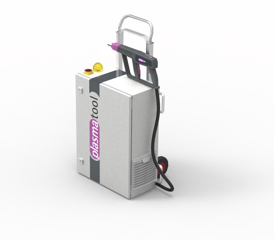
7 2 Description of machine 2.1 Function The machine is operated for the plasma treatment (activation, cleaning) of material surfaces (metals, textiles, glass, plastics) at atmospheric pressure. This plasma treatment can produce significantly improved results during subsequent gluing, painting, printing, coating, wetting, laminating and metallising. 2.2 Machine overview Entire machine No. Component 1 Maintenance for the stand-alone unit 2 Handheld device 3 Cable assembly 4 Mains connection cable (not pictured) BA-PLASMATOOL_EN / F November
 No.")
 4 Cable assembly bushing 5 Functional")

8 2.2.2 Stand-alone unit: Description and connections Fig.: Schematic diagram of the stand-alone unit (front view and top view) No. Component 1 Master switch I/O 2 Signal lamp for machine on/off (red) 3 Warning light for machine is ready for operation (yellow) 4 Cable assembly bushing 5 Functional grounding connection 6 Socket for the mains connection cable (with cover cap) 7 Fan grille 8 Carrying grips for transport 9 Castor wheels 8 November 2017 BA-PLASMATOOL_EN / F

9 10 Grip (pull-out) for rolling transport 11 Position lock for pull-out grip 12 Fuse F1 (see 3.1 Technical data) Handheld device: Description Fig.: Schematic diagram of the handheld device No. Component 1 Handle 2 Protective bar 3 Start stand-alone unit button 4 Start plasma generation button 5 Stand-alone unit ready signal light 6 Cable assembly 7 Spacer 8 Plasma nozzle 2.3 Scope of delivery The scope of delivery includes the following components: Plasma tool machine (consisting of the stand-alone unit and the handheld device with spacer) Mains connection cable Operating instructions BA-PLASMATOOL_EN / F November
10 3 Technical data 3.1 Technical data Description Electrical data Electrical connection Mains fuse Power consumption Value 220 V 240 V AC / 50 Hz / max. 6 A F1 = 10 A / 250 V AC / time lag 1500 W Protection Stand-alone unit: IP 54 handheld device: IP 23 (in accordance with EN 60529) Protection class Class I acc. to IEC Operating voltage of plasma generator Activation period Dimensions Weight Dimensions up to 20 kv Upeak (max. voltage for ignition (briefly)) up to 2 kv RMS (average operating voltage) 50% ED S2 20 minutes 56 kg; lbs 610 x 780(1070) x 430 mm; 24.0 x 30.7(42.1) x 16.9 (width x height x depth) Cable assembly Cable length Minimum cable bending radius Maximum cable extension torsion 5 m 150 mm (5.9 ) ± 90 /m Operating conditions Air humidity < 80% rel. (non-condensing) Temperature 0 40 C; F Storage conditions Air humidity < 80% rel. (non-condensing) Temperature 0 60 C; F Noise emissions Sound level < 60 db(a) at 1 metre away 10 November 2017 BA-PLASMATOOL_EN / F
11 4 Transport/storage 4.1 Storage 4.2 Transport - Store the machine in a dry place. This will prevent the electrical contacts from corroding. - Protect the machine from dirt and foreign objects. The machine is equipped with a trolley for changing location to a hard, level underfloor. To move the machine, please carry out the following steps: - Ensure that the machine is switched off, disconnected from the power supply and cooled down. Check that all moving parts are in a stable, fixed position so that while moving the machine, these parts do not fall off. - Bring the trolley grip to the upper position, by pressing the position lock and pulling the grip upwards until it is solidly engaged. - Carefully tip the machine back, using the trolley grip, so that the machine is standing on its wheels. - You may now move the machine. - ATTENTION: Do not pass the trolley over inclined floors and do not use the trolley to lift the machine or to transport the machine over stairs. After the change of location is concluded, make sure that the machine is positioned at a suitable spot, and that it is stable and secure. BA-PLASMATOOL_EN / F November
12 If you need to move the machine over non-level ground or over stairs, please proceed as follows: - Ensure that the machine is switched off, disconnected from the power supply and cooled down. Check that all moving parts are in a stable, fixed position so that while moving the machine, these parts do not fall off. - Bring the trolley grip to the lower position, by pressing the position lock and pushing the grip downwards until it is solidly engaged. - Carefully tip the machine using the castor wheels until it is level. - Only carry the machine with a second person. - Only use the fixed carrying handles on both sides of the machine for carrying it. After the change of location is concluded, make sure that the machine is positioned at a suitable spot, and that it is stable and secure. Attention damage to machine! - The machine can become damaged if you attempt to move the standalone unit by pulling on one of the cables. Always ensure that there is no nominal tensile stress on the cables. The cable assembly can also become damaged by kinking or by a bending radius that is too tight. Do not kink the cable assembly and adhere to the minimally-permitted bending radius in accordance with the Technical Data Chapter (page 10). - A ceramic component is built into the handle. This can become damaged in the event of hard impacts or falls, and can cause damage to the machine. Always ensure that the handle is secured against impacts and falls during transport. 12 November 2017 BA-PLASMATOOL_EN / F
13 5 Unpacking and installation Caution electrical voltage! Danger: 230 V and high voltage. - The entire machine must not be opened. Both the handheld device and the standalone unit are sealed by the manufacturer. In the event of damage to the seal, the warranty is voided. 5.1 Unpacking Carefully open the machine packaging. Note the information about directions provided on the packaging. Take the machine out of the packaging. After taking the machine out of the packaging, check it and all cables for damage. 5.2 Installation requirements Before installing the machine, the following points must be met: The machine must be fully intact. The machine may only be connected using the provided power cable. The machine's main switch is to be used as an all-pole separator Installation and start-up The stand-alone unit may only be operated while in an upright position. Ensure that a sufficient distance is provided (>150mm) for the ventilation slots. To install the machine, perform the following steps in the specified order: 1. Place the machine on a hard, level floor and make sure that the machine is stable. - Ensure that a distance of at least 150 mm is maintained between all ventilation slots and other objects. - Make sure that the installation location is chosen so that no nominal tensile stress is placed on the cables and lines when using the machine. 2. Open the cover on the machine for the mains connection and connect the mains connection cable to the machine. 3. Plug the mains connection cable into a suitable power outlet with earthing pins. If in doubt, check if the protective earth contact of the power outlet is functional. The machine is installed Using the spacer BA-PLASMATOOL_EN / F November


 To take the spacer off the machine, rotate it until it is positioned")

14 There is a spacer located at the front end of the handheld device. For one thing, this serves to ensure a constant distance to the substrate, and for another, this protects the nozzle from contact, since it can heat up to 200 C during operation. Caution Hot surface! The area around the plasma generator nozzle may reach temperatures of up to 200 C. - Wait until the machine has cooled down if you need to touch this area. - After use, store the machine only in places that are not temperature-sensitive or are not combustible. Putting on and taking off the spacer (e.g. For replacing nozzles/electrodes) To take the spacer off the machine, rotate it until it is positioned at a 45 angle and pull it to the front and off of the machine. To put the spacer on, push it into a 45 position on the machine until it snaps in. Afterwards, rotate it by 45 in one of the four lock positions. Changing the working distance The two uprights in the spacer can be screwed into two further lower positions by unscrewing them. This adjusts to a shorter working distance and thus produces a more intensive plasma treatment for the same treatment time. Attention: Here, the temperature loading in the substrate is also higher. 14 November 2017 BA-PLASMATOOL_EN / F


15 Adjustment of the spacer to the work flow direction To adjust the spacer to the work flow direction, you can rotate it in 90 increments. The spacer engages in these positions. Change the spacer upright (e.g. in the event of breakage or replacement) The uprights can be screwed in and unscrewed by hand. If an upright should break, this will expose a hole in the thread. The remaining threaded portion in the spacer may, for example, be removed with a small hexalobular screwdriver. BA-PLASMATOOL_EN / F November
16 6 Special note on the operation of the plasma process 6.1 General description Treating surfaces with atmospheric plasma has several advantages. Examples include the increase of surface energy by an improved generation of surface wetting. An optimal surface wetting is the first and often decisive step to get a good imprint, a uniform coating, a consistent coat of lacquer or an integrally-bonded adhesive application. The bond at this boundary layer often determines the longevity and adhesive strength of this material pairing. Atmospheric-pressure plasma increases throughput in many industrial processes, while at the same time saving costs for solvents or chemical primers. We have successfully integrated our plasma products into the following application fields: Cleaning of metal, glass and plastics Surface activation and surface functionalisation for optimised wettability Coating for new surface properties Plasma-assisted laminating process Plasma-assisted adhesive bonded joints Plugging and sealing Plasma induced reduction of metal surfaces Chemical-free bleaching of textiles Plasma sterilisation of fabric Handling of food products for quality and shelf life Sterilisation of thermally-unstable plastics Multi-component injection moulding Practically all technical material classes can be efficiently processed under atmospheric pressure: Metals, metal alloys Plastics and composite materials Glass, ceramics, inorganic composites, natural stone Real leather, imitation leather Natural fibres, wood, paper Since the plasma treatment is always just a single part of the entire process, it is important that the additional influencing quantities are known in order to achieve an optimal result. Typical influencing quantities could be: Plasma process: Distance to the substrate, speed, nozzle geometry Substrate/ workpiece: Material composition, contamination, electrical conductivity, thermal conductivity, moisture content Workpiece treatment: Contamination before or after the plasma process, the time duration between the plasma process and the follow-up process Treatment examples can be requested directly from Relyon Plasma GmbH. Additional information on applications, as well as publications, can be found on the website 16 November 2017 BA-PLASMATOOL_EN / F
17 6.2 Notes on the correct handling of the substrates to be treated Caution electrical voltage! Danger from high voltage - Never direct the plasma beam at people or animals. - Never touch the plasma nozzle or the plasma jet when the machine is in operation. - Never touch the workpiece to be treated or its holder during plasma generation. - Make sure that no third party comes into contact with the workpiece to be treated or its holder. - If electrically conductive materials touch the workpiece to be worked on, these materials must be grounded. Since the machine operates with high voltage, certain safety precautions must be met. This applies not only to direct handling of the machine, but also to the workpiece to be handled and its holder. In general, the workpiece holder and all other objects that the workpiece comes into contact with must be earthed. The possibility must be completely excluded, for example, of the user or a third party making contact with the workpiece holder (made from conductive material) during plasma treatment. It is also possible that a third party could receive an electrical shock from the workpiece through the workpiece holder. If a holder made from insulating material is used, it must have a dielectric strength of at least 20 kv. A functional grounding connection is provided on the machine for a special form of plasma treatment involving transferred electric arcs. If you want to use this special application, please contact Relyon Plasma GmbH directly. 6.3 Carrying out surface treatment Depending on the type and condition of your substrate, pre-cleaning before the plasma process can improve the overall outcome. The effect of the treatment depends on the working distance, treatment time, speed and consistency of movement as well as the material to be treated. Ensure that the substrate is not thermally damaged due to movement that is too slow or a working distance that is too low. Treatment examples can be requested directly from Relyon Plasma GmbH. 6.4 Measures to take after the surface treatment To achieve an optimal result, it is important that as little time as possible elapse after the plasma treatment and that the treated surface is not touched or contaminated. Cleaning the surface AFTER the plasma treatment is not recommended. Since the workpiece can heat up depending on the type and duration of the plasma process, it may be necessary to allow the workpiece to first cool down before the next process step is executed in order to not negatively affect the process through the introduction of heat (e.g. in certain bonding processes). Caution Hot surface! The workpiece to be treated can become heated up by the plasma process depending on the process parameters. If necessary, allow the workpiece to cool down before handling it. BA-PLASMATOOL_EN / F November
. 4 3 6 2 5 1 No.")
18 7 Operation 7.1 Controls / displays Caution electrical voltage! Danger of electric shock. - Never reach into the area around the connected plasma generator while it is running or if it has shut down (e.g. to check why the plasma generator has shut down) No. Description Function 1 Master switch Switches the power supply voltage on/off 2 Power on (red) Displays: Power supply is established, master switch is switched on 3 Warning light (yellow) Displays: -flashing: Currently in warm-up time, it is expected to be ready for operation shortly -lit continuously: Machine is ready for operation, assume it to be in plasma operation/supplied with high voltage 4 Handheld device ready (violet) Displays: -flashing: Currently in warm-up time, it is expected to be ready for operation shortly -lit continuously: Machine is ready for operation, assume it to be in plasma operation/supplied with high voltage 5 Start stand-alone unit button Starts the warm-up time in pressed position 6 Start plasma generation button When ready for operation, this starts the plasma generation 18 November 2017 BA-PLASMATOOL_EN / F
19 7.2 Switching on and operating the machine Attention damage to machine! - The machine can become damaged if you attempt to move the stand-alone unit by pulling on one of the cables. Always ensure that there is no nominal tensile stress on the cables. The cable assembly can also become damaged by kinking or by a bending radius that is too tight. Do not kink the cable assembly and adhere to the minimallypermitted bending radius in accordance with the Technical Data Chapter (page 10). - A ceramic component is built into the handle. This can become damaged in the event of hard impacts or falls, and can cause damage to the machine. Always ensure that the handle is secured against impacts and falls during transport. - The machine is classified with a S2 50% switch-on time of 20 minutes. In continuous operation, operate the machine for no longer than 10 minutes, and afterwards allow the machine to cool for at least 10 minutes. Even in the event of shorter operation intervals, a similar cooling-off time must be observed to rule out the possibility of equipment damage. - When the front lock button is released, the compressor and the fan in the standalone unit continue to run for approx. 1 minute to cool down the machine. During this follow-up time, never switch off the machine at the master switch and do not disconnect the power supply. This could cause damage to the machine. To switch the machine on, perform the following steps in the specified order: 1. Switch machine on using master switch (#1). - The lamp (#2) next to the machine's main switch lights up. 2. Hold the handheld device with both hands on the provided grips and place it in a safe area. 3. Press and hold the front handle button (#5) on the handheld device. The warning lamp (#3) and the ready lamp (#4) start to flash, the compressor in the stand-alone unit is enabled and gas flow is audible from the nozzle. After approx. 8 seconds the ready lamp on the hand part and the warning lamp on the stand-alone unit light up steadily. The machine is now ready for operation. Press and hold down the front handle button (#5) until taking a long break or other interruption to your work. 4. Now, press and hold the rear button (#6) of the handheld device to begin the plasma generation. To interrupt the plasma generation only for a brief period of time, release only the rear button. As such, the readiness of the handheld device is maintained without the need to start a new warm-up time. Observe the switch-on time in accordance with the technical data (see page 10). The machine is switched on. BA-PLASMATOOL_EN / F November
20 7.3 Switching off the machine Caution Hot surface! The area around the plasma generator nozzle may reach temperatures of up to 200 C. - Wait until the machine has cooled down if you need to touch this area. - After use, store the machine only in places that are not temperature-sensitive or are not combustible. To switch off, perform the following steps in the order given: 1. Switch off the plasma generation by letting go of both buttons (#5, #6) on the handheld device and place the handheld device in a safe location. 2. Wait until the fan and compressor after-run of approx. 1 minute have ended. 3. Switch off the stand-alone unit by toggling the master switch (#1) to position O. The machine is switched off. Attention damage to machine! When the front lock button is released, the compressor and the fan in the stand-alone unit continue to run for approx. 1 minute to cool down the machine. During this follow-up time, never switch the master switch off and do not disconnect the power supply. This could cause damage to the machine. 8 Taking out of service To take the machine out of service, perform in the following steps in the order given: 1. Switch machine off using master switch (#1). 2. Disconnect the machine from the mains voltage supply: Disconnect the power connector. 3. Close the mains connection socket on the stand-alone unit with the cover cap. The machine is out of service. 20 November 2017 BA-PLASMATOOL_EN / F
21 9 Cleaning and maintenance Caution High voltage! Danger of death! High voltage is produced in the interior of the machine. This voltage is still present after the machine is switched off. - It is forbidden to open the machine. - Before carrying out maintenance or repair work, always disconnect the machine from the power supply. Attention damage to machine! Opening the machine may cause it to be damaged. - It is forbidden to open the machine. 9.1 Cleaning Only clean the outside of the machine. - The machine must be cooled down, switched off and disconnected from the mains voltage supply. - Only clean the machine with a damp cloth. BA-PLASMATOOL_EN / F November


22 9.2 Maintenance for the stand-alone unit Replace the filter mats at least every 5000 operating hours. If working in environments with high levels of dust, they may have to be replaced sooner. You can source the filter mats needed as spare parts from Relyon Plasma GmbH. To change the dust filters, proceed as follows: 1. Disconnect the power supply from the machine. 2. Open the filter holder by the tab with the logo. 3. Use a new filter mat 4. Press the filter holder by the tab until it noticeably clicks into place. 22 November 2017 BA-PLASMATOOL_EN / F

23 9.3 Maintenance for the hand part Caution Hot surface! The area around the plasma generator nozzle may reach temperatures of up to 200 C. - Wait until the machine has cooled down if you need to touch this area. - After use, store the machine only in places that are not temperature-sensitive or are not combustible. Attention damage to machine! The cap nut is designed for tightening and loosening by hand. Do not use a tool to tighten or loosen the cap nut. This may damage the machine. The handheld device contains the plasma nozzle and the inner electrode. These are subject to wear and tear depending on the duration of use, the environmental conditions and the process that was carried out. A thick oxide layer on the plasma nozzle and a marked burnt-in crater on the electrode will impair the ignition properties and increase the temperature of the plasma flame. In these cases the parts must be replaced. To enable access to the nozzle and electrode, remove the spacer in accordance with Chapter Replacing nozzles and electrodes The replacement cycles of the nozzles and electrodes have been determined by reylon plasma in accordance with a standardised test. Deviations are possible, depending on application. - Nozzles in operation with air: Approx. 500 hours - Electrodes in operation with air: Approx hours Depending on application, considerable deviations from these mean values are possible To replace the nozzle and electrode, carry out the following points: BA-PLASMATOOL_EN / F November
24 1. Switch off the machine and wait until the plasma generator has cooled down. 2. Unscrew the nozzle (2) with the cap nut (1) (right-handed thread). Caution: When removing the nozzle, the ceramic sleeve (4) and the spacer for the ceramic sleeve can fall out of the generator housing (5)! 3. Unscrew the electrode with O-ring (3) (right-hand thread) using an Allen key (SW 2.5 mm). 4. Extract the electrode with O-ring (3) out of the coil by hand. 5. Insert the new electrode with O-ring (3) by turning it into the coil and tightly screw it in with a torque wrench (tightening torque 1 Nm). 6. If necessary, first install the spacer for the ceramic sleeve (plastic) and then install the ceramic sleeve (4) back into the generator housing (5). Caution: Observe the correct sequence during installation! 7. Screw the new nozzle (2) with the cap nut (1) to the generator housing (5) again and tighten it hand-tight. The nozzle and electrode are now replaced. Attention: Barrier sleeve made from ceramics in the plasma generator! 1. Barrier sleeves (#4 and #5) are inserted into the plasma generator. 2. Ensure that these barrier sleeves are inserted in the correct sequence. Absent or incorrectly inserted barrier sleeves lead to destruction of the plasma generator. 3. The barrier sleeve (#4) is made of ceramics Caution, risk of breakage! 24 November 2017 BA-PLASMATOOL_EN / F
25 10 Troubleshooting 10.1 Overview of faults / errors Fault / error Cause Rectification Master switch (#1) does not light up No plasma is being generated Fuse defective. Power connector incorrectly connected. No / incorrect voltage supply. There is an error, the machine is not ready. Fuse on the rear side of the machine must be changed. Check the mains unit connection. Check the mains voltage supply. Ensure that both switches are pressed down and that the warm-up time (flashing warning lamp) is up (continuous light). De-energise the machine. Switch on again. Problem cannot be fixed: Contact customer service. Parasitic discharge (discharge at undesired points, e.g. at plasma generator cable connector) Damage from flashover (e.g. to machine parts) Machine or highvoltage cable damaged Take the machine out of operation and contact customer service. Faulty earth connection Check that all earth connections have been established correctly Customer service If the machine is not working properly, contact Relyon Plasma GmbH. You will find the contact information at the end of the operating instructions. BA-PLASMATOOL_EN / F November
26 11 Environment 11.1 Disposal Be mindful of the environment. Used electrical and electronic equipment must not be disposed of along with normal waste. - The machine contains valuable materials that can be recycled. Take the machine to a suitable collection point. 12 Conformity / standards 12.1 CE We declare that this product conforms to CE standards. The product name can be found on the name plate of the machine's housing Product standards The machine satisfies the following requirements and standards: 2014/30/EU EC-EMC guideline Guideline 2014/30/EU of the European Parliament and the Council Directive of 26 February 2014 for the harmonisation of the approximation of the laws of the Member States relating to electro-magnetic compatibility 2014/35/EU EC Low Voltage Directive Guideline 2014/35/EU of the European Parliament and the Council Directive of 26 February 2014 for the harmonisation of the laws of the Member States relating to Electrical equipment for use within certain voltage limits in the market EN :2007+A1:2011 emitted interference EN immunity to interference EN :2014 and EN: :2013 emitted interference EN :2010 safety test EN 50581:2012 Restriction of Hazardous Substances (RoHS) Degree of protection IP23 or IP54 IEC November 2017 BA-PLASMATOOL_EN / F
27 13 Spare and wear parts Item number Description Type Spacer with 2 uprights Spare part Upright for spacer Spare part Spacer for ceramic sleeve Spare part Ceramic sleeve Spare part Cap nut Spare part PB3 electrode with O-ring Wear part A250 nozzle Wear part A350 nozzle Wear part A450 nozzle Wear part Relyon Plasma GmbH Weidener Strasse Regensburg Germany Phone: Fax: info@relyon-plasma.com BA-PLASMATOOL_EN / F November
SAFETY AND OPERATING MANUAL. Original Instructions 5.0
 SAFETY AND OPERATING MANUAL Original Instructions 5.0 Read all safety warnings and all instructions before use. Failure to follow the warnings and instructions may result in electric shock, fire and/or
Instruction Manual. Alarm Unit For Low Gas Level # Read manual before use! Observe all safety information! Keep manual for future use!
 Mess-, Regel- und Überwachungsgeräte für Haustechnik, Industrie und Umweltschutz Lindenstraße 20 74363 Güglingen Telefon +49 7135-102-0 Service +49 7135-102-211 Telefax +49 7135-102-147 info@afriso.de
AIRGOCLEAN 10 E OPERATING MANUAL AIR CLEANER TRT-BA-AIRGOCLEAN10E-TC-001-EN
 AIRGOCLEAN 10 E EN OPERATING MANUAL AIR CLEANER TRT-BA-AIRGOCLEAN10E-TC-001-EN Table of contents Notes regarding the operating manual... 1 You can download the current version of the operating manual and
TTV 1500 / TTV 3000 OPERATING MANUAL CONVEYING FAN TRT-BA-TTV TC EN
 TTV 1500 / TTV 3000 EN OPERATING MANUAL CONVEYING FAN TRT-BA-TTV1500-3000-TC2016-26-004-EN Table of contents Notes regarding the operating manual... 2 You can download the current version of the operating
IDE 20 / IDE 30 / IDE 50 IDE 60 / IDE 80
 IDE 20 / IDE 30 / IDE 50 IDE 60 / IDE 80 EN OPERATING MANUAL OIL HEATER TRT-BA-IDE20-30-50-60-80-TC-001-EN Table of contents Information on the use of this manual... 1 Scope of delivery... 1 General safety...
Millo / Millo pro. Nr x000 / 1805-x000. Ideen für die Dentaltechnik A
 Millo / Millo pro Nr. 1804-x000 / 1805-x000 0609 21-6543 A Ideen für die Dentaltechnik 1 2 3 4 5 6 7 8 9 10 11 12 Millo / Millo pro No. 1804-x000 / 1805-x000 ENGLISH Content Introduction... 15 Symbols...
Important Safety Notice
 Date: 27 th April 2015 Page 1 of 12 SPI Lasers UK Limited Safety Information High Power OEM Fibre Lasers Important Safety Notice This notice outlines important safety related information and must be read
Service package PDAD- -SP (en) Assembly instructions d [ ]
![Service package PDAD- -SP (en) Assembly instructions d [ ]](/thumbs/89/100944426.jpg "Service package PDAD- -SP (en) Assembly instructions d [ ]") Service package PDAD- -SP-12000 (en) Assembly instructions 8068819 1701d [8068821] Original instructions Installation and commissioning are to be carried out only by qualified personnel in accordance with
Service package PDAD- -SP-12000 (en) Assembly instructions 8068819 1701d [8068821] Original instructions Installation and commissioning are to be carried out only by qualified personnel in accordance with
FSW300 Series Flow Switch
 . FSW300 Series Flow Switch - 2 - Series FSW300 Series FSW300 Table of contents page 0 About this operating manual... 4 1 Device description... 5 1.1 Intended use... 5 1.1.1 Reed contact - Switching of
Installation and Operating Instructions DÜRR Regeneration Unit for X-ray developers XR 24, XR24 II, XR 24 Nova, XR 24 Pro
 Installation and Operating Instructions DÜRR Regeneration Unit for X-ray developers XR 24, XR24 II, XR 24 Nova, XR 24 Pro 2006/01 Content Important Information 1. Notes... 3 1.1 CE - Labeling... 3 1.2
User manual UV Flash Dry C1
 HENSEL-VISIT GmbH & Co. KG 1 HENSEL-VISIT GmbH & Co. KG Robert-Bunsen-Str. 3 D-97076 Würzburg GERMANY Tel. +49 (0) 931 27881-0 Fax: +49 (0) 931 27881-50 Email: info@hensel.de Internet: http://www.hensel.de
TIH 300 S / TIH 400 S / TIH 500 S / TIH 700 S / TIH 900 S / TIH 1100 S
 TIH 300 S / TIH 400 S / TIH 500 S / TIH 700 S / TIH 900 S / TIH 1100 S EN OPERATING MANUAL INFRARED HEATING PANEL TRT-BA-TIH300S-TIH400S-TIH500S-TIH700S-TIH900S-TIH1100S-TC-002-EN Table of contents Notes
G4 Pulsed Fiber Laser
 G4 Pulsed Fiber Laser OEM Safety and System Integration Manual Module types C1 and C2 Module type C1 - fitted with IBeam1 delivery optic Module type C2 - fitted with IBeam2 delivery optic 1 1 Preface Definition
Instruction Manual M6627 / Version 7.4. Slide Drying Bench MH6616 MH6616X1
 Instruction Manual M6627 / Version 7.4 Slide Drying Bench MH6616 MH6616X1 Please take your time to read this Instruction Manual in order to understand the safe and correct use of your new Electrothermal
IDE 20 D / IDE 30 D / IDE 50 D / IDE 60 D / IDE 100 D
 IDE 20 D / IDE 30 D / IDE 50 D / IDE 60 D / IDE 100 D EN OPERATING MANUAL OIL HEATER TRT-BA-IDE20D-30D-50D-60D-100D-TC-001-EN Table of contents Notes regarding the operating manual... 1 Safety... 2 Information
HSGM Heißschneide-Geräte
 Operating Instructions Heat cutting machine Model HSG-00 General information These Operating Instructions belong to this product. They contain important information about commissioning and operation. Important
TTK 75 ECO OPERATING MANUAL DEHUMIDIFIER TRT-BA-TTK75ECO-TC-002-EN
 TTK 75 ECO EN OPERATING MANUAL DEHUMIDIFIER TRT-BA-TTK75ECO-TC-002-EN Table of contents Notes regarding the operating manual... 01 Information about the device... 02 Safety... 04 Transport...05 Start-up...05
Propane Flame Projector Safety instructions and operating manual
 Bigflame Propane Flame Projector Safety instructions and operating manual 1 Flame projector Bigflame Safety instructions Caution The directions in this manual must be followed strictly. It is imperative
Adsorption dryer PDAD. (en) Operating instructions g [ ]
![Adsorption dryer PDAD. (en) Operating instructions g [ ]](/thumbs/80/81991997.jpg "Adsorption dryer PDAD. (en) Operating instructions g [ ]") Adsorption dryer PDAD (en) Operating instructions 8068814 1701g [8068816] Original instructions Installation and commissioning are to be carried out only by qualified personnel in accordance with the operating
Adsorption dryer PDAD (en) Operating instructions 8068814 1701g [8068816] Original instructions Installation and commissioning are to be carried out only by qualified personnel in accordance with the operating
SHORT WAVE INFRARED PANEL DRYER
 INSTRUCTIONS FOR: SHORT WAVE INFRARED PANEL DRYER MODEL: IR3000 Thank you for purchasing a Sealey product. Manufactured to a high standard this product will, if used according to these instructions and
TDS 20 R / TDS 30 R / TDS 50 R
 TDS 20 R / TDS 30 R / TDS 50 R EN OPERATING MANUAL ELECTRICAL FAN HEATER TRT-BA-TDS20R-30R-50R-TC-001-EN Table of contents Notes regarding the operating manual... 1 Safety... 1 Information about the device...
ORIGA-SENSOFLEX Displacement Measuring System for Cylinder Series OSP-P
 ORIGA-SENSOFLEX Displacement Measuring System for Cylinder Series OSP-P Contents Description Data Sheet No. Page Overview P-1.50.001E 117-118 Technical Data SFI-plus P-1.50.002E-1, 2 119-120 Dimensions
INSTRUCTIONS. OJ-DV-Relay-Module. OJ Drives A DRIVES PROGRAMME DEDICATED TO VENTILATION SOLUTIONS. Optional module for OJ-DV motor controller
 INSTRUCTIONS OJ-DV-Relay-Module 67439B 10/16 (OSH) 016 OJ Electronics A/S Optional module for OJ-DV motor controller OJ Drives A DRIVES PROGRAMME DEDICATED TO VENTILATION SOLUTIONS Contents 1. Product
IH 025 VOLCANO. Portable Induction Heater. smart mounting
 Portable Induction Heater IH 025 VOLCANO Bedienungsanleitung Instructions for use Mode d emploi Manuale d istruzioni Manual de usuario 2 Portables Induktions-Anwärmgerät IH 025 VOLCANO simatec ag Table
Operating instructions. Static Line. Ionizing bars. Keep for future use! Models (series):
:") Ionizing bars Keep for future use! Operating instructions Models (series): EI RN, EI RNE, EI RN OF, EI RA, EI RAE, EI RA OF EI RD, EI RDE, EI RDA, EI RDAE EI VS, EI VSE, EI VS OF, EI VSA, EI VSAE, EI VSA
Ionizing bars Keep for future use! Operating instructions Models (series): EI RN, EI RNE, EI RN OF, EI RA, EI RAE, EI RA OF EI RD, EI RDE, EI RDA, EI RDAE EI VS, EI VSE, EI VS OF, EI VSA, EI VSAE, EI VSA
Aluminum Heating Mantles
 Aluminum Heating Mantles ON/OFF HOT User Guide Version 1.3 ON/OFF IEC power inlet socket Power supply switch (large-volume models). Power to either the lower part of the element or the upper and lower
Operating instructions Electric agitator RE80Ex. T-Dok-520-GB-Rev.5 Article no Translation of the original operating instructions
 GB Operating instructions Electric agitator RE80Ex T-Dok-520-GB-Rev.5 Article no. 200-0332 Translation of the original operating instructions Thank you for selecting a Krautzberger product. This product
Installation manual plugs and connectors QUICK-CONNECT (63 A)
") EN Installation manual plugs and connectors QUICK-CONNECT (63 A) 60003217 Issue 04.2016 2016-04-01 Table of contents 1 About this manual 3 1.1 Structure of the warnings 3 1.2 Symbols used 4 1.3 Signal
EN Installation manual plugs and connectors QUICK-CONNECT (63 A) 60003217 Issue 04.2016 2016-04-01 Table of contents 1 About this manual 3 1.1 Structure of the warnings 3 1.2 Symbols used 4 1.3 Signal
Electronically controlled instantaneous water heater. MCX: 27300, and models. Installation instructions
 Electronically controlled instantaneous water heater MCX: 27300, 27400 and 27600 models Installation instructions These appliances deliver water not exceeding 50 ºC in accordance with AS3498. 1. Overview
Glue Gun 25W TTB580HTL. Barcode: WARNING: Read the instructions before using the product!
 Glue Gun 25W Original Instructions - MNL_TTB580HTL_V1_140110 TTB580HTL Barcode: 5052931292172 WARNING: Read the instructions before using the product! Congratulations on your purchase of a power tool from
General safety precautions English
 English A min (m 2 ) 550 530 540 510 520 490 500 470 480 450 460 430 440 410 420 390 400 370 380 350 360 330 340 310 320 290 300 270 280 250 260 230 240 210 220 190 200 170 180 150 160 130 140 110 120
General safety precautions English
 English A min (m 2 ) 550 530 540 510 520 490 500 470 480 450 460 430 440 410 420 390 400 370 380 350 360 330 340 310 320 290 300 270 280 250 260 230 240 210 220 190 200 170 180 150 160 130 140 110 120
HXL. Operating instructions
 HXL Operating instructions EN SCOPE OF DELIVERY FOR HXL: 1. HXL line laser 2. Battery adapter BA 3. AA batteries 4. Case 5. Magnetic holder MAH 6. Quick start guide 4 HXL 1. Laser beam output aperture
PRESSURE WASHER MODEL NO: JETSTAR 1750 OPERATION & MAINTENANCE INSTRUCTIONS. WARNING Read the instructions before using the machine PART NO:
 WARNING Read the instructions before using the machine PRESSURE WASHER MODEL NO: JETSTAR 1750 PART NO: 7333230 OPERATION & MAINTENANCE INSTRUCTIONS LS0711 INTRODUCTION Thank you for purchasing this CLARKE
User Manual GV25 GV35 GV702. Company information: Original instructions GV12066 (1)
") User Manual Original instructions GV25 GV35 GV702 Company information: www.vipercleaning.eu info-eu@vipercleaning.com GV12066 (1) 2012-04-10 USER MANUAL ENGLISH TABLE OF CONTENTS Introduction... 4 Manual
User Manual Original instructions GV25 GV35 GV702 Company information: www.vipercleaning.eu info-eu@vipercleaning.com GV12066 (1) 2012-04-10 USER MANUAL ENGLISH TABLE OF CONTENTS Introduction... 4 Manual
Ireland. Australia. New Zealand
 UK Ireland Australia New Zealand 2 3 4 5 Intended use Your Black & Decker vacuum cleaner has been designed to vacuum dry substances. This product is intended for household use only. Safety instructions
Service: to SLK Laboratory Hot Plates glass made of ideas
 SLKServiceV04eng.doc 17 Version: 04.07.2002 Contents Page Contents... 18 1 Safety information... 20 2 Introduction... 21 2.1 Required tools...21 2.2 Required measuring and testing means...21 2.3 Setting
TTV 4500 / TTV 4500 HP / TTV 7000
 TTV 4500 / TTV 4500 HP / TTV 7000 EN OPERATING MANUAL AXIAL FAN TRT-BA-TTV4500-4500HP-7000-TC-003-EN Table of contents The current version of the operating manual can be found at: Notes regarding the operating
OPERATING AND SAFETY INSTRUCTIONS
 IMPORTANT NOTE: Please Read These Operating and Safety Instructions Before Using the BoltBuster OPERATING AND SAFETY INSTRUCTIONS Simple instructions to Get Started with Bolt Buster TM Make sure BoltBuster
Tempest TP420/180 Electric Pressure Washer
 Please dispose of packaging for the product in a responsible manner. It is suitable for recycling. Help to protect the environment, take the packaging to the local amenity tip and place into the appropriate
Steam Trap BK 45 BK 45-U BK 45-LT BK 46
 Steam Trap BK 45 BK 45-U BK 45-LT BK 46 Original Installation Instructions 810437-08 Contents Foreword... 3 Availability... 3 Formatting features in the document... 3 Safety... 3 Use for the intended purpose...
Specifications. Vacuum motor power consumption(w/hp) 1200 / 1.6. Exhaust water pump power consumption(w/hp 800 / 1.1
 1200 / 1.6. Exhaust water pump power consumption(w/hp 800 / 1.1") Specifications Rated voltage (V) AC 110-120V or 220-240V / 50-60Hz Vacuum motor power consumption(w/hp) 1200 / 1.6 Exhaust water pump power consumption(w/hp 800 / 1.1 Exhaust water pump flow (GPH/LPH)
Specifications Rated voltage (V) AC 110-120V or 220-240V / 50-60Hz Vacuum motor power consumption(w/hp) 1200 / 1.6 Exhaust water pump power consumption(w/hp 800 / 1.1 Exhaust water pump flow (GPH/LPH)
SILENT compact /
 SILT compact 2934 0000 / 2934 1000 TRANSLATION OF THE ORIGINAL INSTRUCTIONS FOR USE Made in Germany Ideas for dental technology 21-2245 21052015 / A Contents 1. Introduction...3 1.1 Symbols...3 2. Safety...3
Installer manual AG-AA10. Air/air heat pump IHB GB AG-AA10-30 AG-AA10-40/50
 -30 Installer manual Air/air heat pump -40/50 IHB GB 1516-1 331554 Table of Contents 1 Important information 2 5 Installation 7 Safety information 2 Model combinations 7 Read before starting the installation
English... 5 Čeština Slovenčina Magyarul Polski Русский... 85
 FDS 10150-A 2 English... 5 Čeština... 21 Slovenčina... 37 Magyarul... 53 Polski... 69 Русский... 85 1 FDS 10150-A 4 FDS 10150-A Contents 5 EN Screwdriver INSTRUCTION MANUAL Thank you for your purchase
Original operating instructions Safety switch with guard locking AC901S AC902S
 Original operating instructions Safety switch with guard locking AC901S AC902S 7390914/03 01/2017 Contents 1 Preliminary note...4 1.1 Explanation of symbols...4 2 Safety instructions...4 3 Items supplied...5
UV Flame Supervision System
 7 783 UV Flame Supervision System DETACTOGYR LFE50 Series 02 ISO 9001 The LFE50 is a self-checking UV flame supervision system designed for use with continuously operating burners or for burners running
Translation of the Original Operating Instructions MAB 100 K
 Translation of the Original Operating Instructions MAB 100 K 5 6 4 7 3 2 8 1 9 11 10 General instructions Table of Contents General instructions...3 Safety...5 Components / delivery contents...9 Before
RE-PR3-E-27 3-Phase Panel Mount 27kW
 Page 1 of 6 RE-PR3-E-27 3-Phase Panel Mount 27kW Features: Benefits: 0-10Vdc, 0-5Vdc, 4-20mA or manual via potentiometer control input Over temperature protection with auto reset Enclosed panel mounting
Ireland. Australia. New Zealand
 UK Ireland Australia New Zealand 2 3 4 5 Intended use Your Black & Decker vacuum cleaner has been designed to vacuum dry substances. This product is intended for household use only. Safety instructions
WARNING: Warns of health hazards and identifies possible risks of injury. CAUTION: Indicates possible dangers to the machine or other objects.
 VBT3ASV USER GUIDE SAFETY INFORMATION About this user guide Read this user guide completely before using the machine. Keep this user guide for reference. If you pass your machine on to third parties, it
Sip Vacuum Cleaner 1400/35 Wet & Dry
 Please dispose of packaging for the product in a responsible manner. It is suitable for recycling. Help to protect the environment, take the packaging to the local amenity tip and place into the appropriate
Instructions For Use ENG. LED Magnifier Lamp
 Instructions For Use ENG OPTICA 488 LED Magnifier Lamp ENG Table of Contents 1. For your safety...3 1.1 Designated use...3 1.2 Safety instructions...3 1.3 Warning levels...4 2. Mounting...4 2.1 Mounting
Operating instructions Safety-monitoring module SRB 302X3. 1. About this document. Content
 8 Appendix 8.1 Wiring examples...4 8.2 Start configuration...4 8.3 Sensor configuration...4 8.4 Actuator configuration...5 Operating instructions.............pages 1 to 6 Original 9 EU Declaration of conformity
Vintage Desk Fan. Model: SF1010 (all colours) Helpline. v1.1
 Helpline. v1.1") Vintage Desk Fan Model: SF1010 (all colours) Helpline 01733 404703 SFA1010_IM.indd 1 v1.1 13/11/2014 08:24 IMPORTANT INFORMATION - RETAIN FOR FUTURE USE When using any electrical appliance, basic safety
Vintage Desk Fan Model: SF1010 (all colours) Helpline 01733 404703 SFA1010_IM.indd 1 v1.1 13/11/2014 08:24 IMPORTANT INFORMATION - RETAIN FOR FUTURE USE When using any electrical appliance, basic safety
Operating and Maintenance Instructions
 EATON Germany GmbH Werk Lohmar D-53797 Lohmar Operating and Maintenance Instructions WALFORM Machine Electronically controlled - Conforms to CE MEG-WF385X Status: Sept 2011 MEG-WF385X_Stand Sept 2011 SUITABILITY
INSTRUCTION MANUAL MODEL: 690E
 1 INSTRUCTION MANUAL ALEKO Drywall Sander MODEL: 690E READ THROUGH CAREFULLY AND UNDERSTAND THESE INSTRUCTIONS BEFORE USE Visit our web site for more great products, parts and accessories: 2 3 4 5 6 Caution!
OPERATING INSTRUCTIONS. for the heat press. Secabo TPD7 PREMIUM
 OPERATING INSTRUCTIONS for the heat press Secabo TPD7 PREMIUM Congratulations on the purchase of your Secabo heat press! Please carefully read the operating manual to easily integrate your unit into your
Operating Instruction
 Version 0 21/02/2017 Operating Instruction Hot air dryer english Item No. 108 3106 Elma Schmidbauer GmbH Gottlieb-Daimler-Str. 17 D-78224 Singen Tel. +49 7731 882-0 Fax +49 7731 882-266 info@elma-ultrasonic.com
AUTOMATIC GRANULAR ICE FLAKER
 AUTOMATIC GRANULAR ICE FLAKER INSTRUCTIONS AND WARNINGS 24480 rev. 01 It is strictly forbidden to reproduce this instruction manual or any part thereof. Dear Customer, Congratulations on choosing a
USER S MANUAL BUCKET FAN SERIES BUCKET FAN WHISPER SERIES
 USER S MANUAL BUCKET FAN SERIES BUCKET FAN WHISPER SERIES Bucket Fan 420 Bucket Fan 1055 Bucket Fan 1460 420 1055 1460 2 Bucket Fan CONTENT INTRODUCTION 3 USE 3 WHAT S INCLUDED IN THE BOX 3 DESIGNATION
Guide book ASPIMAX 32. Im Geer 20, Isselburg. Type No.: 403. Serial No.:...
 ASPIMAX 32 Manufacturer: deconta GmbH Im Geer 20, 46419 Isselburg Type No.: 403 Serial No.:... Index On page 1 Basic safety advices 3 2 Technical description 4 2.1 Operating mode separator Filter system
Installation manual extra-low-voltage socket outlets for panel- and surface-mounting
 EN Installation manual extra-low-voltage socket outlets for panel- and 60003221 Issue 04.2016 2016-04-01 Table of contents 1 About this manual 3 1.1 Structure of the warnings 3 1.2 Symbols used 4 1.3 Signal
Instructions manual v.1.0. GD 301 Evo Constant heat sealer. Translation from original instructions
 Instructions manual v.1.0 GD 301 Evo Constant heat sealer Translation from original instructions FOREWORD This machine is part of the Gandus Saldatrici product range. Thanks to our modern production, assembly
ELECTRIC FIREPLACE INSTRUCTION MANUAL. Item No: 050-HA Model No. FP405R-QA
 **WARNING: READ THIS INSTRUCTION MANUAL CAREFULLY BEFORE USE. www.dellaproductsusa.com 909. 344. 2588 ELECTRIC FIREPLACE Model No. FP405R-QA INSTRUCTION MANUAL Item No: 050-HA-50099 2 Thank you for choosing
USER GUIDE. DRENA 2 - User Manual ELECTRICAL PANEL FOR 2 MOTORS - WASTE WATER -
 USER GUIDE DRENA 2 - User Manual ELECTRICAL PANEL FOR 2 MOTORS - WASTE WATER - II CONTENTS 1. SYMBOLS AND WARNINGS... 5 2. GENERAL INFORMATION... 6 3. WARNINGS... 7 4. GENERAL DESCRIPTION... 8 5. INSTALLATION...
Operating instructions
 ebm-papst Mulfingen GmbH & Co. KG Bachmühle D-74673 Mulfingen Phone +49 (0) 793-0 Fax +49 (0) 793-0 info@de.ebmpapst.com www.ebmpapst.com CONTENTS. SAFETY REGULATIONS AND NOTES. Levels of hazard warnings.
INDUSTRIAL VACUUM CLEANER WITH AUTO START/STOP
 INSTRUCTIONS FOR INDUSTRIAL VACUUM CLEANER WITH AUTO START/STOP MODEL NO: PC200SDAUTO.V3 Thank you for purchasing a Sealey product. Manufactured to a high standard, this product will, if used according
AUTOMATIC ICE-CUBE MAKER - INSTRUCTIONS AND WARNINGS
 AUTOMATIC ICE-CUBE MAKER - INSTRUCTIONS AND WARNINGS Dear Customer, Congratulations on having chosen a quality product which will certainly fully meet your expectations. Thank you for having purchased
User and maintenance manual
 GB User and maintenance manual IMPORTANT SAFETY INSTRUCTIONS These instructions shall also be available on website: docs.whirlpool.eu. YOUR SAFETY AND THAT OF OTHERS IS HIGHLY IMPORTANT. This manual and
Operating instructions Safety-monitoring module SRB 302X3. 1 About this document
 1 About this document Operating instructions... pages 1 to 6 Translation of the original operating instructions 1.1 Function This operating instructions manual provides all the information you need for
INSTRUCTION MANUAL FOR ELECTRIC RADIANT INFRARED HEATERS
 www.colorato.net INSTRUCTION MANUAL FOR ELECTRIC RADIANT INFRARED HEATERS MODELS: CLHR-150A / CLHR-180A / CLHR-240A / CLHR-320A Read carefully this manual before using the appliance and keep them for future
3 in 1 Can opener with bottle opener & knife sharpener Model: SP20110N
 3 in 1 Can opener with bottle opener & knife sharpener Model: SP20110N Helpline 01733 404703 v2.0 SP20110N_IM.indd 1 14/11/2014 09:44 IMPORTANT INFORMATION - RETAIN FOR FUTURE USE When using any electrical
ORIGINAL INSTRUCTIONS
 WARNING: Read the instructions before using the machine. POWER WASHER MODEL NO: JETSTAR 1950 PART NO: 7336010 OPERATION & MAINTENANCE INSTRUCTIONS ORIGINAL INSTRUCTIONS LS0617 - ISS 3 INTRODUCTION Thank
Mechanical seals external, single or double, to DIN EN 12756
 INSTALLATION AND OPERATING MANUAL Translation of the original manual Series SCK Bearing pedestal group: 0 Mechanical seals external, single or Keep for future use! This operating manual must be strictly
Handling or using the product improperly and in disregard of the instructions with this mark might result in serious bodily injury or death.
 Please Read: Safety Precautions DC AC In order to ensure that this product is used safely, be sure that you read and understand the following precautions fully and use the product only as directed. Be
TTK 70 S OPERATING MANUAL DEHUMIDIFIER TRT-BA-TTK70S-TC-001-EN
 TTK 70 S EN OPERATING MANUAL DEHUMIDIFIER TRT-BA-TTK70S-TC-001-EN Table of contents Notes regarding the operating manual... 01 Information about the device... 02 Safety...04 Transport...05 Operation...05
Table of Contents. English
 OM-E0799E 000 English Thank you for purchasing VIVA ace Motor Kit. Please read this Operation Manual and the VIVA ace Basic Set Operation Manual carefully before use for operating instructions and care
Vacuum Cleaner User's manual
 User's manual SVC 52BK / SVC 52GR / SVC 52WH Before first use, please read all instructions contained in this user's manual carefully, even if you are already familiar with using similar products. Only
TTK 75 E OPERATING MANUAL DEHUMIDIFIER TRT-BA-TTK75E-TC-002-EN
 TTK 75 E EN OPERATING MANUAL DEHUMIDIFIER TRT-BA-TTK75E-TC-002-EN Table of contents Notes regarding the operating manual... 01 Information about the device... 02 Safety... 04 Transport... 05 Operation...
Please read operating instructions carefully before use and keep it for further reference.
 GB OPERATING INSTRUCTIONS Automatic hot-air welding machine Please read operating instructions carefully before use and keep it for further reference. APPLICATION Overlap and tape welding of coated fabric
Analog Melting Point Apparatus
 Analog Melting Point Apparatus User Guide Version 1.2 7. Turn off to begin cooling. A brass plug can be used if more rapid cooling is required. IEC power inlet socket (at rear) Magnifying lens Capillary
Installation and Operating instructions for. C9900-U battery pack. Version: 2.0 Date:
 Installation and Operating instructions for C9900-U330-0010 battery pack Version: 2.0 Date: 2017-03-23 Table of contents Table of contents 1 Foreword 3 1.1 Notes on the Documentation 3 1.1.1 Liability
 PCE Instruments UK Ltd Units 12/13 Southpoint Business Park Ensign Way, Southhampton Hampshire United Kingdom, SO31 4RF Phone +44(0) 2380 98703 0 Fax +44(0) 2380 98703 9 info@industrial-needs.com Ozone
Installation manual surface mounting plugs and socket outlets, panel mounting plugs and socket outlets with screw connection (16/32 A)
") EN Installation manual surface mounting plugs and socket outlets, panel 60003214 Issue 04.2016 2016-04-01 Table of contents 1 About this manual 3 1.1 Structure of the warnings 3 1.2 Symbols used 4 1.3
EN Installation manual surface mounting plugs and socket outlets, panel 60003214 Issue 04.2016 2016-04-01 Table of contents 1 About this manual 3 1.1 Structure of the warnings 3 1.2 Symbols used 4 1.3
User manual. - A brand of EuroCave Group -
 OXYVD7WCOUS OXY2TVD6COUS User manual - A brand of EuroCave Group - Welcome You have just purchased an ARTEVINO product thank you for your custom. We take particular care in manufacturing our products in
10 & 12 Ventilator. Please read and fully understand the instructions in this manual before operation. Keep this manual safe for future reference
 Please dispose of packaging for the product in a responsible manner. It is suitable for recycling. Help to protect the environment, take the packaging to the local amenity tip and place into the appropriate
THE QUALITY BRAND IN FANS
 THE QUALITY BRAND IN FANS CAUTION! DO NOT THROW AWAY THIS BOOK! READ ALL INSTRUCTIONS CAREFULLY BEFORE INSTALLATION AND FAN OPERATION. Minor design changes or otherwise may result in slight variations
smart mounting Induction Heater IH 070/090 Bedienungsanleitung Instructions for use Mode d emploi Manuale d istruzioni Manual de instrucciones
 Induction Heater IH 070/090 Bedienungsanleitung Instructions for use Mode d emploi Manuale d istruzioni Manual de instrucciones 2 Induktionsheizgerät IH 070/090 simatec ag Table of contents EU Declaration
Alarm System SECURE AS 302
 Alarm System SECURE AS 302 Operating Manual SECURE Light app now available! Table of Contents Before You Start.................................. 4 User Information....................................4
Vacuum Cleaner User's manual
 Vacuum Cleaner User's manual EN Before first use, please read all instructions contained in this user's manual carefully, even if you are already familiar with using similar products. Only use this product
Torrena 42 Ceiling Fan
 Torrena 42 Ceiling Fan Owner s Manual Part # 269268, 269269 Model # 32096, 32097 Exclusively Distributed by: HD Supply Facilities Maintenance, Ltd. Atlanta, GA 30339 2017 Made in China If you are experiencing
AUTOMATIC ICE-CUBE MAKER
 AUTOMATIC ICE-CUBE MAKER INSTRUCTIONS AND WARNINGS 24478 ed. 11-2007 It is strictly forbidden to reproduce this instruction manual or any part thereof. Dear Customer, Congratulations on having chosen
Installation and operating instruction. Digital-Thermostat. Thermo 2
 Installation and operating instruction Digital-Thermostat Thermo 2 1. Scope of supplyl 1 Digital-Thermostat Thermo 2 Incl. suspension device EN 2. Technical data Type of unit: Thermo 2 Power supply: 230
Suits all KPF849 models
 Kambrook - Australia Ground Floor, Suite 2, 170-180 Bourke Rd Alexandria NSW 2015, Australia Locked Bag 2000 Botany NSW 1455 Customer Service Line 1300 139 798 Customer Service Fax 1800 621 337 www.kambrook.com.au
Flow switch. Operating Manual. English manual page Page 1 of 15 Fax:
 Operating Manual www.jlso-tec-trade.de Flow switch English manual page 1-15 Page 1 of 15 Flow switch Table of Contents Page 1 Device Description and Intended Use... 19 1.1 Flow switch version VH...X...
Camarillo 52 Ceiling Fan
 Owner s Manual Camarillo 52 Ceiling Fan Part # 269263, 269259, 269287 Model # 32091, 32092, 32087 Exclusively Distributed by: HD Supply Facilities Maintenance, Ltd. Atlanta, GA 30339 2017 Made in China
PowerVent. Installation manual (GB) English. Store this document in a safe place UK
 English. Store this document in a safe place UK") PowerVent Installation manual (GB) Store this document in a safe place 959.034.03.UK GB Contents Blz Foreword 3 1. Introduction 3 2. CE declaration 4 3. SAFETY 4 3.1 General 4 3.2 Regulations 4 3.3 Precautions
PowerVent Installation manual (GB) Store this document in a safe place 959.034.03.UK GB Contents Blz Foreword 3 1. Introduction 3 2. CE declaration 4 3. SAFETY 4 3.1 General 4 3.2 Regulations 4 3.3 Precautions
Aquamax KF Oil Evaporator. User Manual
 Aquamax KF Oil Evaporator User Manual Edition 1.1 - April 2015 Contents Chapter 1 Introduction... 2 1.1 Instrument Description... 2 1.2 Principle of Measurement... 2 1.3 Instrument Connections... 2 Chapter
A measured step forward
 A measured step forward Operations & Maintenance Manual TM JESCO UV 405-412-440-450-480-550-80 2 LCD LCD PLUS Contents 1. Introduction...3 2. General Principles and Safety Instructions...4 3. Instructions