SECTION 7 AIR CONDITIONING (COOLING) UNIT 41 TROUBLESHOOTING
|
|
|
- Marilyn Tucker
- 6 years ago
- Views:
Transcription
1 SECTION 7 AIR CONDITIONING (COOLING) UNIT 41 TROUBLESHOOTING
2 UNIT OBJECTIVES After studying this unit, the reader should be able to Select the correct instruments for checking an air conditioning unit with a mechanical problem. Calculate the correct operating suction pressures for both standard- and high-efficiency airconditioning equipment under various conditions. Calculate the standard operating discharge pressures at various ambient conditions. Select the correct instruments to troubleshoot electrical problems in an air-conditioning system. Check the line- and low-voltage power supplies. Troubleshoot basic electrical problems in an air conditioning system. Use an ohmmeter to check the various components of the electrical system.
3 INTRODUCTION Troubleshooting air-conditioning equipment involves both the mechanical and electrical systems Symptoms may overlap Mechanical problems may appear to be electrical and vice versa Technicians must diagnose problems correctly
4 MECHANICAL TROUBLESHOOTING Gages and temperature-testing equipment are used when performing mechanical troubleshooting Always be aware of the system refrigerant R-410a pressures are much higher than R-22 R-22 gages on R-410a systems will be over pressurized and can become damaged Not all refrigerant oils are compatible, so gages should be used on only one type of refrigerant
5

6 LOW PRESSURE GAGE Pressure scale Gage needle Temperature scales for various refrigerants Vacuum range Gages provide temperatures and pressures for saturated refrigerants
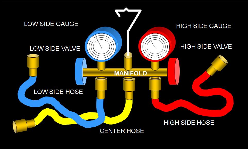
7 GAGE MANIFOLD USAGE Displays the low- and high-side pressures while the unit is operating These pressures can be converted to the saturation temperatures Gage manifolds are used whenever the pressures need to be known for the system Gages are connected to service ports Used to calculate superheat and subcooling
8 LOW PRESSURE GAGE 68.5 psig 40 F This low side gage indicates a suction pressure of 68.5 psig, which means that the refrigerant is boiling at 40 F in the evaporator
9 Schrader valves to access refrigeration circuit When pin in the valve is pushed in, the valve is open and the refrigerant circuit can be accessed When pressure on the pin is removed, the valve seals itself closed and the refrigerant circuit is once again sealed closed
10 SERVICE VALVES Line port Service port Valve stem Device port Packing gland
11 SERVICE VALVES Backseated Position Service port is sealed, line port is open to the device port Normal operating position
12 SERVICE VALVES Cracked off the Backseat Position Service port is open to the line port and device port Position used for taking system pressure readings Position used for adding or removing system refrigerant
13 SERVICE VALVES Midseated Position Service port is open to the line port and device port Position used for system evacuation and leak checking
14 SERVICE VALVES Frontseated Position Service port is open to the device port Line port is sealed off Position used for pumping the system down
15 WHEN TO CONNECT THE GAGES Gage manifolds should not be connected every time a system is serviced Small amounts of refrigerant escape each time the gages are connected and removed from a sealed system Short gage hoses will limit the amount of refrigerant lost Low-loss fittings should be used
16 LOW-SIDE GAGE READINGS Used to compare the actual evaporating pressure to the normal evaporating pressure Standard-efficiency systems usually have a refrigerant boiling temperature of about 35 F cooler than the entering air temperature Under increased loads, the evaporator is absorbing extra sensible and latent heat from the air Gage readings when the system is operating in or close to design range will verify system s true performance
17 HIGH-SIDE GAGE READINGS Used to check the relationship of the condensing refrigerant to the ambient air temperature Standard efficiency air-cooled condensers condense the refrigerant at no more than 30 F higher than the ambient temperature High-efficiency condensers normally condense the refrigerant at a temperature as low as 20 F higher than the ambient temperature
18 TEMPERATURE READINGS For determination of the system s superheat and subcooling temperatures Common temperatures used for evaluation are: Indoor air wet-bulb and dry-bulb temperatures Outdoor air dry-bulb temperature Suction-line temperature Condenser outlet temperature Compressor discharge line temperature
19
20
21
22
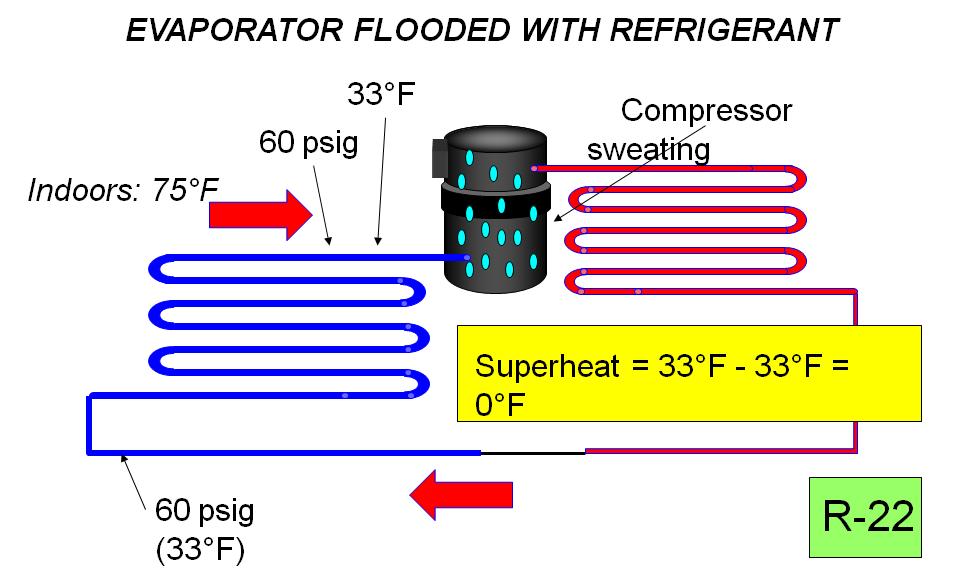
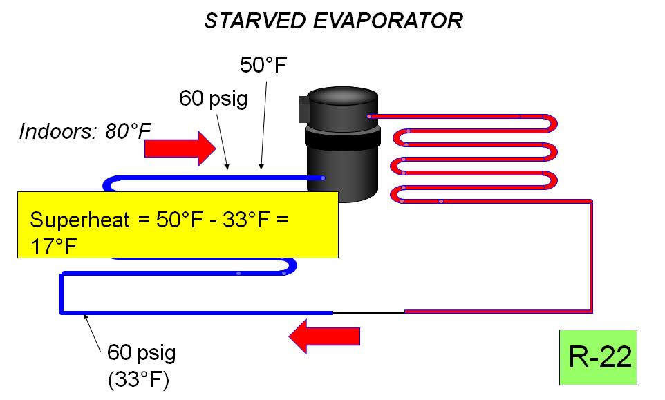
23 CHARGING SYSTEMS IN THE FIELD When the system is operating correctly under design conditions, there should be a prescribed amount of refrigerant in the condenser, the evaporator, and the liquid line The amount of refrigerant in the evaporator can be measured by superheat The amount of refrigerant in the condenser can be measured by subcooling
24 FIELD CHARGING THE TXV SYSTEM Reduce the airflow across the condenser to simulate a 95 F outside air temperature The superheat check will not work for the TXV because it is designed to maintain a constant superheat of 8 to 12 under any load condition A subcooling check of the condenser can be used to check the system charge Typical subcooling circuit will subcool the liquid refrigerant from 10 to 20 cooler than the condensing temperature Excessive subcooling indicates an overcharge
25 ELECTRICAL TROUBLESHOOTING You need to know what the readings should be to know whether the actual readings are correct or not Begin any electrical troubleshooting by verifying that the power supply is energized and that the voltage is correct If the power supply voltage is correct, move on to the various components
26 L1 L2 RELAY OR CONTACTOR CONTROL CIRCUIT MOTOR RUN START START RELAY
27 L1 L2 Fuses Contactor contacts Contactor coil 3A 25A
28 L1 L2 Contactor coil CC1 Disconnect CC2 CC 24V from inside house S R C Compressor Low pressure control Condenser fan motor Wiring diagram of basic components in a control and compressor circuit
29 COMPRESSOR ELECTRICAL CHECKUP Technicians need to be careful when condemning a compressor Many condemned compressors are not bad Unnecessary labor and material costs Compressor problems can be mechanical or electrical
30 ELECTRICALLY CHECK A SINGLE-PHASE COMPRESSOR Make certain wires are disconnected from the compressor Make certain all compressor terminals are clean Check resistance from windings to ground (ohmmeter or megohmmeter) Check resistance of the start and run windings
31 ELECTRICALLY CHECK A SINGLE- PHASE COMPRESSOR (cont d.) Check continuity between run and start terminals Check voltage between common and run terminals and between common and start terminals Voltage readings should be within 10% of the rated voltage
32 ELECTRICALLY CHECK A THREE-PHASE COMPRESSOR Check resistance from windings to ground Make certain wires are disconnected from the compressor Make certain all compressor terminals are clean Check each winding from terminal to terminal The resistance readings should be the same in all windings
33 MECHANICALLY CHECKING A COMPRESSOR If the supply voltage is correct, the compressor should start If the compressor does not start, the compressor may be stuck Reversing the direction of the motor may free the motor
34 COMPRESSOR CAPACITY One or more cylinders may not be functioning properly Simulate design conditions as closely as possible If voltage is correct and amperage is very low, the compressor is not pumping to capacity Indicated by a high suction pressure and a low head pressure
35 TROUBLESHOOTING THE CIRCUIT ELECTRICAL PROTECTORS FUSES AND BREAKERS Open circuit breakers or blown fuses should be treated with caution Do not reset or replace a tripped breaker or fuse without trying to determine what caused the fuse to blow or the breaker to trip
36 SUMMARY - 1 Troubleshooting air-conditioning equipment involves both the mechanical and electrical systems Mechanical problems may appear to be electrical and vice versa Gages and temperature-testing equipment are used when performing mechanical troubleshooting Gage manifolds are used whenever the pressures need to be known for the system Gages are used to calculate superheat and subcooling
37 SUMMARY - 2 Gage manifolds should not be connected every time a system is serviced Short gage hoses will limit refrigerant loss Standard-efficiency systems usually have a refrigerant boiling temperature of about 35 F cooler than the entering air temperature Standard efficiency air-cooled condensers condense the refrigerant at no more than 30 F higher than the ambient temperature
38 SUMMARY - 3 Temperature readings are needed to calculate evaporator superheat and condenser subcooling The amount of refrigerant in the evaporator can be measured by superheat The amount of refrigerant in the condenser can be measured by subcooling Typical subcooling circuit will subcool the liquid refrigerant from 10 to 20 cooler than the condensing temperature
39 SUMMARY - 4 Begin any electrical troubleshooting by verifying that the power supply is energized and that the voltage is correct Use an ohmmeter to check compressor windings for grounds, shorts and open circuits Compressor voltage readings should be within 10% of the rated voltage If the supply voltage to the compressor is correct, the compressor should start
Electrical Problems. Fuse(s) blow or circuit breaker trips. Does the unit use circuit breakers or fuses? Replace with correct fuse(s)
 blow or circuit breaker trips. Does the unit use circuit breakers or fuses? Replace with correct fuse(s)") Electrical Problems Fuse(s) blow or circuit breaker trips Does the unit use circuit breakers or fuses? Fuse(s) Circuit breakers Are the fuses dual element time delay? Is the circuit breaker HACR rated?
Electrical Problems Fuse(s) blow or circuit breaker trips Does the unit use circuit breakers or fuses? Fuse(s) Circuit breakers Are the fuses dual element time delay? Is the circuit breaker HACR rated?
Table of Contents. Service Procedures. Service Procedures. Measuring Superheat (4) Measuring Subcooling (5) Airflow Calculation (6-8)
 Measuring Subcooling (5) Airflow Calculation (6-8)") Table of Contents Refrigeration Cycle Service Procedures Measuring Superheat (4) Measuring Subcooling (5) Airflow Calculation (6-8) Solving Problems Identifying Low System Charge (9-11) Identifying High
Table of Contents Refrigeration Cycle Service Procedures Measuring Superheat (4) Measuring Subcooling (5) Airflow Calculation (6-8) Solving Problems Identifying Low System Charge (9-11) Identifying High
Installation Instructions
 PREFERREDT SERIES AIR CONDITIONER WITH PURONR REFRIGERANT 1-1/2 TO 5 NOMINAL TONS Installation Instructions Fig. 1 --- 538A NOTE: Read the entire instruction manual before starting the installation. TABLE
AIR CONDITIONING. Carrier Corporation 2002 Cat. No
 AIR CONDITIONING Carrier Corporation 2002 Cat. No. 020-016 1. This refresher course covers topics contained in the AIR CONDITIONING specialty section of the North American Technician Excellence (NATE)
SECTION 2 SAFETY, TOOLS AND EQUIPMENT, SHOP PRACTICES UNIT 10 SYSTEM CHARGING
 SECTION 2 SAFETY, TOOLS AND EQUIPMENT, SHOP PRACTICES UNIT 10 SYSTEM CHARGING UNIT OBJECTIVES After studying this unit, the reader should be able to Describe how refrigerant is charged into systems in
SECTION 7 AIR CONDITIONING (COOLING) UNIT 40 TYPICAL OPERATING CONDITIONS
 UNIT 40 TYPICAL OPERATING CONDITIONS") SECTION 7 AIR CONDITIONING (COOLING) UNIT 40 TYPICAL OPERATING CONDITIONS UNIT OBJECTIVES After studying this unit, the reader should be able to Explain what conditions will cause the evaporator pressure
SECTION 7 AIR CONDITIONING (COOLING) UNIT 40 TYPICAL OPERATING CONDITIONS UNIT OBJECTIVES After studying this unit, the reader should be able to Explain what conditions will cause the evaporator pressure
SECTION 7 AIR CONDITIONING (COOLING) UNIT 40 TYPICAL OPERATING CONDITIONS UNIT OBJECTIVES
 UNIT 40 TYPICAL OPERATING CONDITIONS UNIT OBJECTIVES") SECTION 7 AIR CONDITIONING (COOLING) UNIT 40 TYPICAL OPERATING CONDITIONS UNIT OBJECTIVES After studying this unit, the reader should be able to Explain what conditions will cause the evaporator pressure
SECTION 7 AIR CONDITIONING (COOLING) UNIT 40 TYPICAL OPERATING CONDITIONS UNIT OBJECTIVES After studying this unit, the reader should be able to Explain what conditions will cause the evaporator pressure
Installation Instructions
 Performance Series Heat Pumps with PURONr Refrigerant 1 --- 1/2 to 5 Nominal Tons Installation Instructions Fig. 1 --- A07532 NOTE: Read the entire instruction manual before starting the installation.
Calhoon MEBA Engineering School. Study Guide for Proficiency Testing Refrigeration
 Calhoon MEBA Engineering School Study Guide for Proficiency Testing Refrigeration 1. To prevent an injury when working with refrigerants, what safety precautions are necessary? 2. When halogens are in
SECTION 8 AIR SOURCE HEAT PUMPS UNIT 43 AIR SOURCE HEAT PUMPS
 SECTION 8 AIR SOURCE HEAT PUMPS UNIT 43 AIR SOURCE HEAT PUMPS UNIT OBJECTIVES After studying this unit, the reader should be able to Describe the operation of reverse-cycle refrigeration (heat pumps) Explain
Instructors: Contact information. Don Reynolds Doug McGee Factory Tech Support
 Contact information Instructors: Don Reynolds 616-560-9903 Doug McGee 517-294-3932 Factory Tech Support 888-593-9988 Product Improvements for 2017 Todays Objectives Job Site Information Sheets Low Ambient
SECTION 5 COMMERCIAL REFRIGERATION UNIT 21 EVAPORATORS AND THE REFRIGERATION SYSTEM UNIT OBJECTIVES 3/22/2012 REFRIGERATION
 SECTION 5 COMMERCIAL REFRIGERATION UNIT 21 EVAPORATORS AND THE REFRIGERATION SYSTEM UNIT OBJECTIVES After studying this unit, the reader should be able to Define high-, medium-, and low-temperature refrigeration.
Installation Instructions
 24AHA4 Performance Series Air Conditioner with Puron Refrigerant 1-1/2 to 5 Nominal Tons Installation Instructions Fig. 1-24AHA4 A07532 SAFETY CONSIDERATIONS Improper installation, adjustment, alteration,
To accomplish this, the refrigerant fi tis pumped throughh aclosed looped pipe system.
 Basics Refrigeration is the removal of heat from a material or space, so that it s temperature is lower than that of it s surroundings. When refrigerant absorbs the unwanted heat, this raises the refrigerant
SERVICING PROCEDURE R-410A LEAK TEST EVACUATION CHARGING. Bard Manufacturing Company, Inc. Bryan, Ohio Manual Page 1 of 11
 SERVICING PROCEDURE R-410A LEAK TEST EVACUATION CHARGING Bard Manufacturing Company, Inc. Bryan, Ohio 43506 Since 1914...Moving ahead, just as planned. Manual No.: 2100-479 Supersedes: NEW File: Volume
User s Information and Installation Instructions
 Outdoor Air Conditioner User s Information and Installation Instructions 2-Stage R-410A Split System These units have been designed and tested for capacity & efficiency in accordance with A.H.R.I. Standards.
Some of these procedures need to be performed to conform to requirements of the Clean Air Act.
 Leak Detection, Recovery, Evacuation and Charging Four basic service procedures used to repair and maintain a mechanical refrigeration system are leak detection, evacuation, recovery, and refrigerant charging.
The Saturation process
 SOUTH METROPOLITAN TAFE WA The Saturation process Dennis Kenworthy 8/5/2016 A student study guide to measuring and interpreting the saturation process of refrigeration and air-conditioning equipment System
Installation Instructions
 25HHA4 Performance Series Heat Pump with Puron Refrigerant 1-1/2 to 5 Nominal Tons Installation Instructions Fig. 1-25HHA4 A07532 SAFETY CONSIDERATIONS Improper installation, adjustment, alteration, service,
HEAT PUMPS. Carrier Corporation GT72-01 Cat. No
 HEAT PUMPS Carrier Corporation 2003 GT72-01 Cat. No. 020-018 1. This refresher course covers topics contained in the HEAT PUMPS specialty section of the North American Technician Excellence (NATE) certification
Vehicle Level Heating and Air Conditioning Description and Operation A/C System - Manual. A/C System - Manual
 1 of 5 4/7/2008 8:32 AM Home Account Contact ALLDATA Log Out Help Select Vehicle New TSBs Technician's Reference Component Search: METRO TOYOTA OK 1999 Ford Truck F 450 2WD Super Duty V10-6.8L VIN S Vehicle
Installation Manual for CCS Cased Coils with SC, SD, SW Compressor Units and R-410A Refrigerant
 EarthLinked TXV Kit Installation Manual for CCS Cased Coils with SC, SD, SW Compressor Units and R-410A Refrigerant CONTENTS PAGE Pre-Installation 3 Cased Coil Conversion 4 System Start-Up 17 TXV CCS-410-KIT
Refrigeration/Troubleshooting Manual
 Refrigeration/Troubleshooting Manual P.O. Box 245 Syracuse, NY 13211 www.roth-america.com 888-266-7684 P/N: 2300100910 Table of Contents: Section 1: Geothermal Refrigeration Circuits Overview... 2 Water-to-Air
How to Diagnose a TXV Failurek
 How to Diagnose a TXV Failurek There has been much written and many jokes made about the misdiagnosis of TXV (Thermostatic expansion valves) and rightly so. This article will cut straight to the point
Warm Case Troubleshooting Guide 9/18/2014
 Introduction Warm cases can be caused by various problems which require thorough troubleshooting. Begin the investigation with questions to store personnel asking for information such as when the last
Superheat charging curves for technicians
 This website requires certain cookies to work and uses other cookies to help you have the best experience. By visiting this website, certain cookies have already been set, which you may delete and block.
SECTION 5 COMMERCIAL REFRIGERATION UNIT 22 CONDENSERS UNIT OBJECTIVES UNIT OBJECTIVES 3/22/2012
 SECTION 5 COMMERCIAL REFRIGERATION UNIT 22 CONDENSERS UNIT OBJECTIVES After studying this unit, the reader should be able to explain the purpose of the condenser in a refrigeration system. describe differences
Section 1: Theory of Heat Unit 3: Refrigeration and Refrigerants
 Section 1: Theory of Heat Unit 3: Refrigeration and Refrigerants Unit Objectives After studying this chapter, you should be able to: Discuss applications for high-, medium-, and low temperature refrigeration.
INSTALLATION INSTRUCTIONS
 INSTALLATION INSTRUCTIONS R 410A Ducted Horizontal Air Conditioner Product Family: HC4A3 Fig. 1 - HC4A3 NOTE: Read the entire instruction manual before starting the installation. TABLE OF CONTENTS PAGE
SECTION 2 SAFETY, TOOLS & EQUIPMENT, SHOP PRACTICES UNIT 8 SYSTEM EVACUATION
 SECTION 2 SAFETY, TOOLS & EQUIPMENT, SHOP PRACTICES UNIT 8 SYSTEM EVACUATION UNIT OBJECTIVES After studying this unit, the reader should be able to Describe a standing pressure test. Choose a leak detector
REFRIGERANT RECOVERY Log Book
 REFRIGERANT RECOVERY Log Book R E F R I G E R A N T L O G 1) Policy 2) Troubleshooting 3) Condensers Replaced 4) Compressors Replaced 5) Appliance Disposal 6) Accidental Venting 7) R22 NEW 8) R22 Recover
INSTALLATION INSTRUCTIONS
 INSTALLATION INSTRUCTIONS R 410A Ducted Horizontal Heat Pump Product Family: HC4H3 Figure 1 - HC4H3 NOTE: Read the entire instruction manual before starting the installation. TABLE OF CONTENTS PAGE SAFETY
INSTALLATION GUIDE. 4AC 14* ASA1 SERIES R-410a CONDENSING UNITS R-410A ATTENTION, INSTALLER! ATTENTION, USER!
 4AC 14* ASA1 SERIES R-410a CONDENSING UNITS INSTALLATION GUIDE R-410A ATTENTION, INSTALLER! After installing the system, show the user how to turn off electricity to the unit. Point out control and switch
Checking the Charge on a Heat Pump in the Winter
 Checking the Charge on a Heat Pump in the Winter When you ask many people nowadays how to check the charge on a heat pump during low outdoor temps they will say that you need to weigh in and weigh out
REFRIGERATION AND AIR CONDITIONING RÉFRIGÉRATION ET CLIMATISATION POST-SECONDARY NIVEAU POSTSECONDAIRE
 INSTRUCTIONS AND COMPETITION DETAILS INSTRUCTIONS ET DÉTAILS DU CONCOURS REFRIGERATION AND AIR CONDITIONING RÉFRIGÉRATION ET CLIMATISATION POST-SECONDARY NIVEAU POSTSECONDAIRE 1. Test Project Details This
Condensing Unit Installation and Operating Instructions
 Bulletin WCU_O&I 01 June 2003 Condensing Unit Installation and Operating Instructions WCU Air Cooled Condensing Unit Table of Contents Section 1. Section 2. Section 3. Section 4. Section 5. Section 6.
Air Conditioning Operation and Troubleshooting Matt Dunham
 Air Conditioning Operation and Troubleshooting Matt Dunham Major Components (10 Minutes) Compressor heart of the system, causes refrigerant to flow by increasing the pressure of the refrigerant Metering
Otherwise, you can continue reading the file on the following pages.
 If you d like to be able to print this file out to study off-line or use on the job, a printable version is available for an administrative fee of $3.97 USD. To download the unlocked file, click here.
MODEL URS-1: FACTORY RETROFIT PROGRAM
 MODEL URS-1: FACTORY RETROFIT PROGRAM The USR-1 unit has gone through extensive testing in order to attain maximum performance. It has been determined that in order to set the unit for all weather operation,
Class 1: Basic Refrigera0on Cycle. October 7 & 9, 2014
 Class 1: Basic Refrigera0on Cycle October 7 & 9, 2014 Refrigeration Cycle 4 key components needed in a basic refrigera0on cycle: 1. Compressor 2. Condenser 3. Evaporator 4. Metering Device Compressor Compressor
A/C-HEATER SYSTEM - MANUAL
 A/C-HEATER SYSTEM - MANUAL 1986 Isuzu Trooper II 1986 A/C-HEATER SYSTEM Isuzu A/C-Heater Systems - Manual P UP, Trooper II * PLEASE READ THIS FIRST * CAUTION: When discharging air conditioning system,
Operation and Maintenance Manual
 Warranty Information Ritchie Engineering guarantees YELLOW JACKET products to be free of defective material and workmanship which could affect the life of the product when used for the purpose for which
RecoverX Oil-Filled Hermetic Refrigerant Recovery System. Operation and Maintenance Manual
 RecoverX Oil-Filled Hermetic Refrigerant Recovery System Operation and Maintenance Manual Table of Contents Page General Safety Instructions 2-3 System Overview 3 Operating Guide 4 Restart Procedure 4
4A6H5049E1000B 208/230/1/ /8 7/8 7/8 7/8 DURATION 208/230/1/ /230/1/ SPINE FIN 13 LBS., 10 OZ. YES
 Service Facts Split System Heat Pump 4A6H5049E1000B IMPORTANT This document contains a wiring diagram, a parts list, and service information. This is customer property and is to remain with this unit.
Pressure Enthalpy Charts
 Pressure Enthalpy Charts What is a p-h Diagram? A p-h diagram is a diagram with a vertical axis of absolute pressure and a horizontal axis of specific enthalpy. "Enthalpy is the amount of energy in a substance
RSES Technical Institute Training Manual 2 72 hours, 72 NATE CEHs, 7.2 CEUs
 Lesson 1 - Trade Tools Explain the importance of using proper tools and test instruments. List the various types of wrenches and describe their use. Describe the proper procedures for bending, flaring,
EBAC MODEL CD425 ( ) INDUSTRIAL DEHUMIDIFIER OWNER S MANUAL
 INDUSTRIAL DEHUMIDIFIER OWNER S MANUAL") EBAC MODEL CD425 (1018110) INDUSTRIAL DEHUMIDIFIER OWNER S MANUAL Ebac Industrial Products 704 Middle Ground Boulevard Newport News, VA 23606 Tel: 757 873 6800 Fax: 757 873 3632 Website: www.ebacusa.com
EBAC MODEL CD425 (1018110) INDUSTRIAL DEHUMIDIFIER OWNER S MANUAL Ebac Industrial Products 704 Middle Ground Boulevard Newport News, VA 23606 Tel: 757 873 6800 Fax: 757 873 3632 Website: www.ebacusa.com
KML F SERIES KML H SERIES
 NO.: ISSUED: REVISED: 73085 AUG. 18, 1999 JAN. 13, 2004 HOSHIZAKI MODULAR CRESCENT CUBER MODELS KML F SERIES KML H SERIES SERVICE MANUAL IMPORTANT Only qualified service technicians should attempt to service
4A6H5042G1000A 208/230/1/ DURATION - SCROLL 3/4 208/230/1/ NO (Use BAYKSKT263) YES YES PROPELLER DIRECT
 YES YES PROPELLER DIRECT") Service Facts Split System Heat Pump 4A6H5042G1000A CAUTION IMPORTANT This document contains a wiring diagram, a parts list, and service information. This is customer property and is to remain with this
Service Facts Split System Heat Pump 4A6H5042G1000A CAUTION IMPORTANT This document contains a wiring diagram, a parts list, and service information. This is customer property and is to remain with this
User s Information and Installation Instructions
 Outdoor Air Conditioner User s Information and Installation Instructions 13 SEER R-410A High Efficiency Split System These units have been designed and tested for capacity & efficiency in accordance with
Reliability is a beautiful thing TM MODULAR CRESCENT CUBER KM-500MAH KM-500MWH KM-500MRH SERVICE MANUAL
 Reliability is a beautiful thing TM MODULAR CRESCENT CUBER KM-500MAH KM-500MWH KM-500MRH SERVICE MANUAL NUMBER: 73104 ISSUED: NOV. 7, 2002 REVISED: DEC. 16, 2003 IMPORTANT Only qualified service technicians
PARALLEL RACK SYSTEM INSTALLATION & OPERATIONS MANUAL With Master Rack Compressor Sequencer
 PARALLEL RACK SYSTEM INSTALLATION & OPERATIONS MANUAL With Master Rack Compressor Sequencer 5/16 Rev. A 57-02509 2 Contents INTRODUCTION... 4 WARNING LABELS AND SAFETY INSTRUCTIONS... 5 PS SERIES PARALLEL
208/230/1/60 5/8 5/8 5/8 5/8 5/8 20 CLIMATUFF /230/1/
 Service Facts Split System Heat Pump 4TWB4024E1000A IMPORTANT This document contains a wiring diagram, a parts list, and service information. This is customer property and is to remain with this unit.
IMPORTANT. HOSHIZAKI provides this manual primarily to assist qualified service technicians in the service and maintenance of the icemaker.
 73105 IMPORTANT Only qualified service technicians should attempt to service or maintain this icemaker. No service or maintenance should be undertaken until the technician has thoroughly read this Service
208/230/1/ CLIMATUFF /230/1/ YES NO NO PROPELLER 23-1 DIRECT / /230/1/ SPINE FIN
 Service Facts Split System Cooling 4TTB3030D1000A IMPORTANT This document contains a wiring diagram, a parts list, and service information. This is customer property and is to remain with this unit. Please
Refrigeration System with a Capillary Tube and a Thermostat
 Exercise 2-1 Refrigeration System with a Capillary Tube Part A: REFRIGERATION CIRCUIT OBJECTIVE When you have completed this part, a refrigeration circuit using a capillary tube as a metering device will
Service Facts. Split System Cooling 3.0 Ton 4A7A6036J-SF-1B-EN. January A7A6036J1000A
 Service Facts Split System Cooling 3.0 Ton 4A7A6036J1000A Note: Graphics in this document are for representation only. Actual model may differ in appearance. SAFETY WARNING Only qualified personnel should
4TTB3030D1000B 208/230/1/60 4TTB3036D1000B 208/230/1/ RECIP /230/1/ RECIP YES YES
 Service Facts Split System Cooling 4TTB18E1000A, 4TTB24E1000A 4TTBD1000B, 4TTB36D1000B 4TTB3-SF-1B CAUTION UNIT CONTAINS R-410A REFRIGERANT R-410A OPERATING PRESSURE EXCEEDS THE LIMIT OF R-22. PROPER SERVICE
SERVICE ASSISTANT OVERVIEW FDSI Online Training
 Author: Dale T. Rossi Online Editor: Zachary Williams SERVICE ASSISTANT OVERVIEW FDSI Online Training May 5, 2009 Table Service Assistant Description... 2 Installing the Main Unit... 3 Ambient Temperature...
KM-61BAH KM-101BAH KM-151BAH
 NO. M006-749 ISSUED: FEB. 18, 2008 REVISED: JUN. 12, 2008 HOSHIZAKI SELF-CONTAINED CRESCENT CUBER MODEL KM-61BAH KM-101BAH KM-151BAH SERVICE MANUAL IMPORTANT Only qualified service technicians should attempt
Everything You. NEED to KNOW. TXV does this by keeping the coil supplied
 Everything You NEED to KNOW About TXVs } With the higher SEER air conditioners, technicians need to reacquaint themselves with thermostatic expansion valves B Y A L M A I E R Before the 13 SEER minimum
HNC-120BE-L/R-B HNC-150BE-L/R-B HNC-180BE-L/R-B HNC-210BE-L/R-B COUNTER SHOWCASE MODEL SERVICE MANUAL HOSHIZAKI
 NO. S051-800 ISSUED: MAR. 26, 2010 REVISED: HOSHIZAKI COUNTER SHOWCASE MODEL HNC-120BE-L/R-B HNC-150BE-L/R-B HNC-180BE-L/R-B HNC-210BE-L/R-B SERVICE MANUAL IMPORTANT This manual should be read carefully
4TTB3060D1000B 208/230/1/60 35 SCROLL /230/1/ /8
 Service Facts Split System Cooling 4TTB3048D1000B, 4TTB3060D1000B CAUTION IMPORTANT This document contains a wiring diagram, a parts list, and service information. This is customer property and is to remain
HOSHIZAKI MODULAR CRESCENT CUBER MODEL KM-280MAH KM-280MWH SERVICE MANUAL
 NO. 73117 ISSUED: AUG. 15, 2004 REVISED: HOSHIZAKI MODULAR CRESCENT CUBER MODEL KM-280MAH KM-280MWH SERVICE MANUAL IMPORTANT Only qualified service technicians should attempt to service or maintain this
INSTALLATION INSTRUCTIONS
 R-410A Two-Stage Split System Air Conditioner Product Family: H4A6, C4A6, T4A6 H4A8, C4A8, T4A8 These instructions must be read and understood completely before attempting installation. DANGER, WARNING,
T-SERIES Air Conditioner. T29 Model INSTRUCTION MANUAL nvent Rev. I P/N
 T-SERIES Air Conditioner T29 Model INSTRUCTION MANUAL Rev. I P/N 89104464 TABLE OF CONTENTS Warranty and Return Policy...2 IMPORTANT NOTICE...2 RECEIVING THE AIR CONDITIONER...3 HANDLING AND TESTING THE
The Essentials Of Working With R-410A
 The Essentials Of Working With R-410A By Norm Christopherson Several major manufacturers are producing comfort air conditioning equipment using refrigerant 410A. The trend towards the use of 410A continues
Service Facts. WARNING: HAZARDOUS VOLTAGE - DISCONNECT POWER and DISCHARGE 4TTR6024-SF-1B. Split System Cooling 4TTR6024A1000B CAUTION CAUTION WARNING
 Service Facts Split System Cooling 4TTR6024A1000B 4TTR6024A1000B 208/230/1/60 18 20 CLIMATUFF - SCROLL 1-2 208/230/1/60 13.0-52 PROPELLER 27.6-1 DIRECT - 1 3200 1-1/8 835 208/230/1/60 0.74 SPINE FIN 1-24
NUMBER: ISSUED: JULY 13, /336 73/23 STACKABLE CRESCENT CUBER KM-1300SWH-E SERVICE MANUAL FOR QUALIFIED SERVICE PERSON HOSHIZAKI
 89/336 73/23 NUMBER: 73141 ISSUED: JULY 13, 2006 STACKABLE CRESCENT CUBER KM-1300SWH-E SERVICE MANUAL FOR QUALIFIED SERVICE PERSON HOSHIZAKI IMPORTANT Only qualified service technicians should attempt
Service Facts. WARNING: HAZARDOUS VOLTAGE - DISCONNECT POWER and DISCHARGE 4TTB6-SF-3. Split System Cooling 4TTB6048A1000A, 4TTB6049A1000A CAUTION
 Service Facts Split System Cooling 4TTB6048A1000A, 4TTB6049A1000A CAUTION 4TTB6-SF-3 UNIT CONTAINS R-410A REFRIGERANT R-410A OPERATING PRESSURE EXCEEDS THE LIMIT OF R-22. PROPER SERVICE EQUIPMENT IS REQUIRED.
7/8 NO NO NO PROPELLER DIRECT / /230/1/ SPINE FIN /8 8 LBS., 0 OZ. YES 7/8 3/8
 Service Facts Split System Cooling 4TTR3060D1000A CAUTION IMPORTANT This document contains a wiring diagram, a parts list, and service information. This is customer property and is to remain with this
Split Floor-Mounted Cooling System Operation Care Installation Manual
 Split Floor-Mounted Cooling System Operation Care Installation Manual CT14TSA CT13TSA CT12TSA CT34TSA CT1TSA CT14TSA-LA CT13TSA-LA CT12TSA-LA CT34TSA-LA CT1TSA-LA www.apexwinecellars.com Apex 17631 S Susana
SECTION PACKAGED COMPRESSOR AND CONDENSER UNITS
 SECTION 236200 - PACKAGED COMPRESSOR AND CONDENSER UNITS PART 1 - GENERAL 1.1 RELATED DOCUMENTS A. Drawings and general provisions of the Contract, including General and Supplementary Conditions apply
INSTALLATION AND MAINTENANCE INSTRUCTIONS 4SCU16LT Series Split System Air Conditioner WARNING
 INSTALLATION AND MAINTENANCE INSTRUCTIONS 4SCU16LT Series Split System Air Conditioner WARNING The equipment covered in this manual is to be installed by trained and experienced service and installation
WMHP Series R410a Heat Pump INSTALLATION INSTRUCTIONS
 WMHP Series R410a Heat Pump INSTALLATION INSTRUCTIONS **WARNING TO INSTALLER, SERVICE PERSONNEL AND OWNER** Altering the product or replacing parts with non authorized factory parts voids all warranty
Publication # RD-0003-E Rev 1, 10/17 SERVICE GUIDELINES HCFC R22 TO HFC REFRIGERANT BLENDS
 Publication # RD-0003-E Rev 1, 10/17 SERVICE GUIDELINES HCFC R22 TO HFC REFRIGERANT BLENDS Refrigerant R22 is widely used for residential and commercial air conditioning, as well as commercial refrigeration
4TTR6036B1000A 208/230/1/ CLIMATUFF - SCROLL 3/4 3/4 3/4 3/4 3/4 208/230/1/ NO YES NO PROPELLER DIRECT
 Service Facts Split System Cooling 4TTR6036B1000A IMPORTANT This document contains a wiring diagram, a parts list, and service information. This is customer property and is to remain with this unit. Please
SECTION 7 AIR CONDITIONING (COOLING) UNIT 39 CONTROLS
 UNIT 39 CONTROLS") SECTION 7 AIR CONDITIONING (COOLING) UNIT 39 CONTROLS UNIT OBJECTIVES After studying this unit, the reader should be able to Describe the control sequence for an air-conditioning system. Explain the function
SECTION 7 AIR CONDITIONING (COOLING) UNIT 39 CONTROLS UNIT OBJECTIVES After studying this unit, the reader should be able to Describe the control sequence for an air-conditioning system. Explain the function
SECTION 7 AIR CONDITIONING (COOLING) UNIT 39 CONTROLS UNIT OBJECTIVES UNIT OBJECTIVES. After studying this unit, the reader should be able to
 UNIT 39 CONTROLS UNIT OBJECTIVES UNIT OBJECTIVES. After studying this unit, the reader should be able to") SECTION 7 AIR CONDITIONING (COOLING) UNIT 39 CONTROLS UNIT OBJECTIVES After studying this unit, the reader should be able to Describe the control sequence for an air-conditioning system. Explain the function
SECTION 7 AIR CONDITIONING (COOLING) UNIT 39 CONTROLS UNIT OBJECTIVES After studying this unit, the reader should be able to Describe the control sequence for an air-conditioning system. Explain the function
R100 Oil-Less Refrigerant Recovery Unit
 R100 Oil-Less Refrigerant Recovery Unit Operation Manual 1 INTRODUCTION Welcome to simple, efficient refrigerant recovery with your new YELLOW JACKET Refrigerant Recovery Unit, R100. This unit combines
SERVICE MANUAL FOR QUALIFIED SERVICE PERSON HOSHIZAKI 89/336 73/23 SELF-CONTAINED CRESCENT CUBER KM-150BAF-E KM-150BWF-E
 89/336 73/23 NUMBER: 73108 ISSUED: APRIL 19, 2000 REVISED: JAN. 13, 2004 SELF-CONTAINED CRESCENT CUBER KM-150BAF-E KM-150BWF-E SERVICE MANUAL FOR QUALIFIED SERVICE PERSON HOSHIZAKI IMPORTANT Only qualified
347002K/177002K/34900
 Service Manual Models: 347002K/177002K 34900/347012K Manifold Block Style Recovery/Recycling/Recharging Unit For R-12 or R-134a Only TABLE OF CONTENTS: Theory of Operation and Safety Precautions... 2 Depressurizing
EarthLinked SW Series Compressor Unit R-410A Quik-Start Instructions
 EarthLinked SW Series Compressor Unit R-410A Quik-Start Instructions CONTENTS PAGE Pre-Installation 3 Placement & Mechanical Information 4 System Application Options 10 Antifreeze Protection 14 Electrical
Corp L9 Revised HS27 SERIES UNITS SPECIFICATIONS. Model No. HS HS HS HS27-042
 Service Literature Corp. 9619 L9 Revised 08 2004 HS27 SERIES UNITS HS27 The HS27 is a 14 SEER high efficiency residential split system condensing unit which features a scroll compressor. It operates much
Installation Manual for. Series HWM and Non-ETI HYDRONIC WATER MODULE with SC and SD COMPRESSOR UNITS and R-410 REFRIGERANT
 EarthLinked TXV Kit Installation Manual for Series HWM and Non-ETI HYDRONIC WATER MODULE with SC and SD COMPRESSOR UNITS and R-410 REFRIGERANT CONTENTS PAGE Pre-Installation 3 Hydronic Water Module Conversion
T-Series Air Conditioner T15 Model
 INSTRUCTION MANUAL T-Series Air Conditioner T15 Model Protecting Electronics. Exceeding Expectations. McLean Cooling Technology 11611 Business Park Blvd N Champlin, MN 55316 USA Tel 763-323-8200 Fax 763-576-3200
Hoshizaki America, Inc.
 Hoshizaki America, Inc. Low-Profile Modular Crescent Cuber Models KML-351MAH KML-351MWH A Superior Degree of Reliability SERVICE MANUAL www.hoshizaki.com Number: 73149 Issued: 6-10-2008 IMPORTANT Only
Service Step by Step Trouble-Shooting Check-List
 WARNING: Only Data Aire trained technician or experience technicians should be working on Data Aire Equipment. Protect yourself at all times and work safe. Date: Dates at the job site: From: to Job#: Serial#:
EBAC MODEL CD425 ( ) INDUSTRIAL DEHUMIDIFIER OWNER S MANUAL
 INDUSTRIAL DEHUMIDIFIER OWNER S MANUAL") EBAC MODEL CD425 (1018110) INDUSTRIAL DEHUMIDIFIER OWNER S MANUAL Ebac Industrial Products, Inc. 700 Thimble Shoals Blvd, Suite 109 Newport News, VA. 23606-2575 Tel: (757) 873 6800 Fax: (757) 873 3632
EBAC MODEL CD425 (1018110) INDUSTRIAL DEHUMIDIFIER OWNER S MANUAL Ebac Industrial Products, Inc. 700 Thimble Shoals Blvd, Suite 109 Newport News, VA. 23606-2575 Tel: (757) 873 6800 Fax: (757) 873 3632
CUSTOMIZED TEACHER ASSESSMENT BLUEPRINT HVAC MAINTENANCE TECHNOLOGY. Test Code: 5937 Version: 01
 CUSTOMIZED TEACHER ASSESSMENT BLUEPRINT HVAC MAINTENANCE TECHNOLOGY Test Code: 5937 Version: 01 Specific competencies and skills tested in this assessment: Introduction to HVAC Identify HVAC systems Demonstrate
Product Data. Features/Benefits. 07DA, DB 07EA, EB, ED Condensing Units. 06D, 06E Compressors. 3 to 40 Nominal Tons
 Product Data 07DA, DB 07EA, EB, ED Condensing Units 3 to 40 Nominal Tons 06D, 06E Compressors An excellent choice for your built-up system Carrier 07 Series condensing units built for the engineer who
HVAC Service Technicians Training Center
 HVAC Service Technicians Training Center 48-03 32 nd Place, Long Island City, NY 11101 Tel: (718) 472-0404 (718) 472-0414 Fax: (718) 433-0676 Introduction to the Refrigeration Cycle: Part 1 (AC/R-1) This
T-Series Air Conditioner T20 Model
 INSTRUCTION MANUAL T-Series Air Conditioner T20 Model Protecting Electronics. Exceeding Expectations. McLean Cooling Technology 11611 Business Park Blvd N Champlin, MN 55316 USA Tel 763-323-8200 Fax 763-576-3200
Determining Real Time Performance of Residential AC Systems. Presented at the RESNET Conference San Antonio, TX February 28, 2006
 Determining Real Time Performance of Residential AC Systems Presented at the RESNET Conference San Antonio, TX February 28, 2006 Bill Spohn testo, Inc. testo Worldwide 100 90 80 70 60 50 40 30 20 10 0
R.A.S.E.R.S System. Installation Guide
 R.A.S.E.R.S System Installation Guide Contents R.A.S.E.R.S System components... 1 Required components for heating, cooling, and hot water...1 Provided...1 Not provided...2 Optional components...3 R.A.S.E.R.S
Service Facts. WARNING: HAZARDOUS VOLTAGE - DISCONNECT POWER and DISCHARGE 4TTR6048-SF-1A. Split System Cooling 4TTR6048A1000A CAUTION CAUTION WARNING
 Service Facts Split System Cooling 4TTR6048A1000A 4TTR6048A1000A 208/230/1/60 28 45 CLIMATUFF - SCROLL 1-2 208/230/1/60 21.2-104 PROPELLER 27.6-1 DIRECT - 1 4260 1-1/5 825 208/230/1/60 1.0 SPINE FIN 1-24
KM-630MAH KM-630MWH KM-630MRH
 NO.: ISSUED: 73114 JUNE 23, 2004 HOSHIZAKI MODULAR CRESCENT CUBER MODEL KM-630MAH KM-630MWH KM-630MRH SERVICE MANUAL IMPORTANT Only qualified service technicians should attempt to service or maintain this
T-SERIES Air Conditioner. T43 Model INSTRUCTION MANUAL nvent Rev. I P/N
 T-SERIES Air Conditioner T43 Model INSTRUCTION MANUAL Rev. I P/N 10-1008-145 TABLE OF CONTENTS Warranty and Return Policy...2 IMPORTANT NOTICE...2 RECEIVING THE AIR CONDITIONER...3 HANDLING AND TESTING
Liebert Small System MCD and PFH Condensers (1-5 Ton) Warranty Inspection Check Sheet
 Warranty Inspection Check Sheet") The following information must be fully completed and forwarded to your local Liebert sales office to establish your equipment warranty. Installer Address Owner Address Owner e-mail address Installation
The following information must be fully completed and forwarded to your local Liebert sales office to establish your equipment warranty. Installer Address Owner Address Owner e-mail address Installation
KITS COMMON TO HEATING AND COOLING EQUIPMENT 504,652M 03/04. Supersedes 503,249M
 2004 Lennox Industries Inc. Dallas, Texas KITS COMMON TO HEATING AND COOLING EQUIPMENT 504,652M 03/04 Supersedes 503,249M Litho U.S.A. COMPRESSOR REPLACEMENT KIT INSTALLATION INSTRUCTIONS FOR COMPRESSOR