Tranquility Digital (DXM2) Troubleshooting Guide
|
|
|
- Allan Lee
- 6 years ago
- Views:
Transcription

 Basic Refrigeration Summary 25 Refrigeration Troubleshooting 26-27 Auxiliary Heat Check 28 Checking Pump Output")


1 Tranquility Digital (DXM2) Troubleshooting Guide Residential Packaged DIGITAL Geothermal Heat Pumps 97B0601N01 Rev.: 4/3/14 Introduction 2 Troubleshooting Flow Chart 3-9 Flow Chart Reference Symbols and Diagrams 10 Contactor Chart 11 Verifying Pump Feedback Signal 11 Removing Powerhead on Modulating Valve Checking Compressors Reversing Valve Touch Test Chart 16 Performance Troubleshooting Functional Troubleshooting Commissioning Worksheet: Typical Water Source Refrigeration Circuit 24 (Heating Cycle) Basic Refrigeration Summary 25 Refrigeration Troubleshooting Auxiliary Heat Check 28 Checking Pump Output 28 Compressor Contactor Voltage Check 29 Check CCH for 24 Volts 29 Verifying Contactor 29 Verifying Capacitor 30 Checking Pump Power Cord 30 Replacing Variable-Speed Pump Power Head 31 Verifying Power at Molded Plug 31 for Compressor Verifying Antifreeze 32 Second Stage Verification 33 Table of Contents Verifying 24V at Reversing Valve 34 Checking Reversing Valve at DXM2 34 A0-2 Jumper 35 Checking for Power at DXM2 35 Verifying DC Voltage on DXM2 Board 36 for Modulating Valve Check TXV Bulb Test 37 Verifying Dipswitch Position 38 Replacing High Pressure Water Switch 38 Verifying a Thermistor Turning Breaker on in Panel 41 or Aux Heat Control Static Pressure Check 41 Locating Tstat Version and DXM2 Version 42 UltraCheck EZ Motor Diagnostic Tool 42 Checking Dipswitches on DXM2 43 Magnet Test to Shift Reversing Valve 43 Checking Blower Line Voltage 44 Modulating Valve Loses Configuration 44 Hard Reset of Thermostat 45 Units Having LT1 Lockouts In Heating 46 Definitions of Conditions DXM2 Board Layout and Dipswitches 49 DXM2 Controls Wiring Diagrams ATC Thermostat Screens and Set Up Revision History 64
2 Introduction Troubleshooting ClimateMaster Tranquility Digital Packaged Heat Pumps is quite straightforward. Most problems relate to water fl ow. Either there isn t enough water fl ow or the entering water temperature is improperly supplied. Most service problems can be addressed without refrigerant gauges. In fact, installing gauges on packaged heat pumps can do more harm than good because packaged heat pumps contain less refrigerant compared to split systems. The fi rst thing to do is always perform a water side check (Heat of Extraction for Heating or Heat of Rejection for Cooling) to determine if the unit is operating properly. Set up and diagnostics are made easier using the communicating thermostat (ATC32) or the communicating service tool (ACDU01). You must have ATC32 or ACDU01 to properly work on ClimateMaster Tranquility Digital units that use the DXM2 control board. Follow the fl ow chart on the following pages to help diagnose and solve your issue. 2 Geothermal Heat Pump Systems
3 Troubleshooting Flow Chart Did unit start? Check that unit voltage reads: V Establish power Does thermostat say Communication? Is there power to DXM2 24V? ( V) A-W Verify that Dipswitch 1 on S3 is in On position A-Z If it is still not communicating, check the thermostat wire (Be sure it is not running parallel along power wire). Ensure all wiring is landed properly on both DXM2 and thermostat. Hard reset the thermostat B-K Is the unit properly confi gured? See Section 3.0 on page 56. Verify that the DXM2 s dipswitches are set properly. B-G Disconnect and reconnect the wires from the DXM2. This will reset the thermostat. Also ensure there are no wire nuts; solder wires if they need to be extended. Hook Service Tool up to board. Does Service Tool communicate with board? Replace board if current board still does not function The unit did start but it locked out Check Fault Code from thermostat or service tool Fault Check that the compressor is not in a thermal overload See Fault Codes and Possible Causes Check that there are 24 volts at CC on DXM2 board and a call for heating or cooling Check for 24V at contactor volts A-A A-F A-K A-M Replace the DXM2 Board Check and possibly replace wiring Next Page 3
4 Troubleshooting Flow Chart Continued Replace DXM2 board The unit starts but the pump does not Is there voltage to the pump? ( V) Check that the A0-2 jumper on DXM2 board is in PWM position Does the low voltage wiring have a broken wire? Check DC Voltage at DXM2 Board A0-2-Ground =.5-10 VDC Is voltage in this range? A-O A-V Verify how the units are confi gured in the thermostat (refer to Section Unit Configuration on page 53). Be sure unit is configured for Variable Speed Pump Single if unit is on it s own loop. If unit shares a loop with other units, then ensure that the unit is confi gured for Variable Speed Pump Parallel. Replace wire harness Check DC Voltage at DXM2 Board T1-Ground = 3-4 VDC (Pump off) 0-2 VDC (Pump on) Is voltage in this range? A-J Replace pump power head A-P My unit has a Modulating Valve. Is valve opening? Is the valve having trouble shutting completely and/or is the unit locking out? Valve opens or closes correctly Verify Valve and powerhead alignment Verify A0-2 jumper is in 10V position. A-V Check What are the T set points? Control defaults are 7 heating and 10 cooling. Open loop units with EWT less than 50 will need to lower T to 4-5 in the heating mode. B-L Manually open the valve 100%. Remove powerhead from valve with powerhead still energized. Then verify that the notches on valve body are in the correct position. Be sure unit is confi gured for Modulating Valve. See Section 3.2 on page 56. A-C Third notch aimed down in unit position. Then reattach powerhead. Next Page 4 Geothermal Heat Pump Systems
5 Troubleshooting Flow Chart Continued Verify that the wiring on the valve and DXM2 Board are correct. See wiring diagrams on pages Verify that the DC voltage on DXM2 between A0-2 and GND. Voltage should be between VDC. This is the output from the board to the valve. A-X The unit uses a modulating valve but the thermostat continues to show a variablespeed pump. B-J Connect a piece of thermostat wire between T1 and GND on DXM2 so the DXM2 board sees no feedback. Valve does function but when the unit shuts off, the valve remains open. A-C Verify 3/4 Valve Dipswitch or 1 Valve Dial Does blower turn on? Verify in confi guration that the unit is confi gured correctly for ECM Is V at the blower motor? B-I Check continuity on communicating harness from DXM2 to Module. Is there a broken wire? Check the wire harness and replace if needed Replace wire harness Does the motor try to spin when giving a G call? Next Page Replace defective part Use Emerson EZ Tool to troubleshoot motor and verify motor or module B-F 5
6 Troubleshooting Flow Chart Continued Is the blower loud? Check your model s airfl ow confi guration. See Section 3.1 on page 56. Verify that all grilles and registers are open. B-D Check static pressure There are no faults, but does the compressor start? A-A Verify comp contactor. Verify capacitor. Turn off power and allow 5 minutes for discharge. Then verify with volt meter the UF reading compare to UF reading on capacitor. Is capacitor good? A-N Replace capacitor. A-Q Verify voltage to compressor at molded plug Replace molded plug and wire harness A-D Turn power off and remove molded plug on compressor. Measure resistance between C-S and C-R. Replace compressor Unit starts but does not shift to cooling Verify that you have cooling call at thermostat Call for cooling Check reversing valve connection at DXM2. Do you have 24 VAC? A-U Verify that Dipswitch 1:4 is on If Dipswitch 1:4 is on, replace board A-T Verify 24V at reversing valve Replace defective wiring Replace solenoid on reversing valve In order to increase pressure and move a reversing valve that is sticking, place unit in heating mode and then remove blower door. Just after removing door, energize the valve. If it still doesn t shift, try a strong magnet to pull over internal slide while energizing. B-H Verify RV operation Next Page 6 Geothermal Heat Pump Systems A-E Replace the reversing valve if it still does not shift
7 Troubleshooting Flow Chart Continued Unit does not seem to be in second stage. This is indicated by the performance check being about 30% (low). Verify that Does you have DXM2 second CCH have stage call 24V? Verify whether the thermostat is confi gured for multi-stage operation A-L Verify that Dipswitch 1:4 is on If Dipswitch 1:4 is on, replace board A-S Does the rectifi er plug on the side of the compressor have VDC? With unit running in second stage, check amp draw of comp. Next, remove rectifi er plug. Amps should be lower after removing plug. Reattach plug and verify that amps return to previous higher reading. Replace the rectifi er plug Replace compressor The unit started but runs and loop temp continue to drop in the heating mode Verify the antifreeze level where applicable. Remember that EWT below 45 needs 15 freeze protection. Verify with appropriate hydrometer. A-R Antifreeze has been verified as having 15 freeze protection. Then cut the JW3 jumper Is there enough loop in the ground? Is the loop making good contact? (Example: Is your vertical loop grouted from top to bottom?) Is the loop turbulent? Min 2500 Reynolds Number. Use Pressure Drop Software to verify Next Page 7
8 Troubleshooting Flow Chart Continued The unit periodically locks out on LT1 in heating or high pressure in cooling Does this unit Is there more than one unit have a Variable Speed Pump and sharing a is it confi gured for common loop? parallel pumping? Verify pump is supplying enough fl ow using Pressure Drop Software. Closed loop gpm per ton. See Lockout Faults on page 51 under Fault Codes Properly confi gure unit. See Section 3.3 and Section 3.4 on page 57. ATC Thermostat says ECM Confi guration Error Is the thermostat confi gured for the proper model of the unit? (Example: TZ036) This is found on thermostat s unit confi guration menu. Does the unit have the correct ECM Motor? Check the ECM table, which is in the unit s IOM.Compare to the motor in the unit. Replace with correct motor Confi gure The unit does run but ATC Thermostat says Service Needed This is the Unit Performance Sentinel. In cooling mode if LT2 is 40 or lower or LT1 is 125 or greater. In heating mode if LT2 is 125 or greater. A-F Go to Faults Code 8. Next Page 8 Geothermal Heat Pump Systems
9 Troubleshooting Flow Chart Continued Unit runs but does not satisfy A-G HE = Verify the Water Side Performance HR = Heat Extraction in BTUs (Heating) Heat Rejection in BTUs (Cooling) Calculate using the formula found on A-G. Check with performance data. Is unit within 10%? The unit is running. However, there is a load issue. The home is losing or gaining more than the capacity of the heat pump. Verify load using a manual J program. You may also need to perform a blower door test for true infiltration and thermal imaging for locating heat loss. Also consider a duct blast to verify that air is being delivered properly. If water fl ow and airfl ow are good, then verify refrigerant charge. Calculate superheat and subcooling. A-H Then check for proper TXV operation before adding or removing charge. A-Y Adjust charge if needed to proper superheat and subcooling ranges. The unit runs but auxiliary heat is not working Is the thermostat calling for auxiliary heat or emergency heat? Does unit have V at auxiliary heat strip? A-I Does DXM2 have 24 VDC at EH1 and/or EH2? Verify that confi guration is set to auxiliary heat in thermostat. See section on page 55. Turn breaker on in panel or in auxiliary heat control B-C Replace DXM2 Replace heat strap board Does the heat strip control board have the same 24 VDC as the DXM2? Replace wire harness 9
10 Reference Symbols and Diagrams for Flow Chart 10 Geothermal Heat Pump Systems
11 Contactor Chart A-A Motor does not hum Contactor closed Burned contacts Open in low voltage circuit Incorrect wiring Open motor wiring Open overload switch Motor hums, cuts off on overload circuit breaker or blows fuses Check contactor Compressor tight or stuck High discharge pressure not equalized Low line voltage Burnt out or open winding n-condensibles in refrigerant circuit Buzzing rmal voltage to coil Low voltage to coil Contactor open Contactor defective, jammed or hung up Wrong gauge of thermostat wire Low voltage from transformer t buzzing Loose wire voltage to coil Voltage to coil power to control circuit Coil open circuited U1 Alarm Relay C Status Fault ESD OVR H Off On A Off Off On S3 S2 A0-1 A Acc1 Relay S1 Acc2 Relay Factory Use P3 R NO1 NC1 COM NO2 NC2 COM R Verifying Pump Feedback Signal P11 Gnd T1 T2 T2 T3 COH COM AO2 AO1 Gnd 0-2 VDC with pump on 3-4 VDC with pump off A-B Ensure correct wiring on T1=Yellow, A0-2=White. If not, voltage may look good but pump may not operate. 11


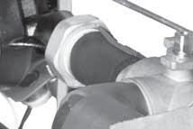
12 A-C Removing Powerhead on ¾-Inch Modulating Valve On 3/4 valve, be sure that dip switch is moved up or toward center of valve and valve closes. For Proper Valve-to-Head Alignment Before removing power head, go to manual mode and open valve to 100%. Stay on that screen and with the valve powered open, remove power head. Verify or rotate physical valve to the position. Open Closed 12 Geothermal Heat Pump Systems


13 Removing Powerhead on 1-Inch Modulating Valve A-C 1) Rotate dial to 1 on the 1-Inch valve. 2) The 1-inch valve includes a tool to remove the power head. See previous page for proper valve-to-head alignment. Open Closed 13
14 A-D Compressor Ohms Table Compressor Checking Compressors C-S Ohms C-R Ohms Unit ZPS TZ024, TE026 ZPS TZ036, TE038 ZPS TZ048, TE049 ZPS TZ060, TE064 ZPS TE072 ZPS TZ030 ZPS TZ042 te: Readings are good ± 7% te: Reading S-R = C-S + C-R Readings Example: ZPS20 S-R = 2.94 Ohms Compressor with Open Internal Overload Overload opens C Compressor with Open Run Winding C S R S R If both R and S are open to common, Internal overload is open. Compressor with Shorted Windings C Open run winding (infinite) resistance. Start winding shows measurable resistance. Compressor Winding Shorted to Ground C Suction Line S R S R te: If not, O resistance will be close to it. C-S and C-R will have high resistance above 3 ohms. Check for ground by placing one lead on suction line. 14 Geothermal Heat Pump Systems

15 Megohm Values of Copeland Compressors An Alternative Way of Checking Compressors For years servicemen have used megohmeters to evaluate compressor motor windings. However, most megohmeter manufacturers publish guidelines that apply to open motors. For this reason, Emerson Climate Technologies has investigated the use of megohmeters on hermetic and semihermetic compressors. When using megohmeters to evaluate the motor insulation of compressors, it is important to understand that they should not be used as one would a volt-ohm meter. A single megohmeter reading gives little insight into the condition of a motor s insulation. Megohmeters are best used as a part of a regular maintenance program to monitor trends (over several months). For example, one might record a megohm value and compare it to a previous reading. If subsequent readings show a trend of lower and lower values, then corrective action (such as system clean up) should be taken. Emerson does not incorporate the megohmeter into any of its quality checks. All Copeland compressors must pass U.L. required tests using hi-potential current leakage testers ( hi-pot ). Studies performed by Emerson have found that compressors with megohmeter readings as low as 0.5 megohms still pass the hi-pot. A-D There are many factors that affect megohm readings including contaminated refrigerant, oil level, refrigerant in oil and current leakage through electrical fusites or terminal plates. Any external electrical components connected to the compressor terminals also affect megohm readings. Wires, contactors and relays all leak current and will decrease compressor megohmeter readings if not disconnected. As mentioned earlier a single megohm reading cannot be used to condemn a compressor since many other factors are involved. However, limits can be placed on megohm values that dictate action be taken. Emerson has found that these limits are related to the rated voltage of the compressor. Megohm values equal to or greater than 1000 ohms per volt are probably acceptable. For example, a 460 volt compressor might show a megohm reading of 460,000 ohms or 0.46 megohm. Compressors with rated voltages of 208 to 230 volts would then be operable at megohm values of to megohms; for simplicity, Emerson has set the limit at 0.5 megohms before a compressor is condemned. Figure 1 shows the required procedure for checking compressors with a megohmeter. New compressors that have never been installed will not need any system clean-up procedures so long as the megohm reading is above 0.5. A baseline reading must be established for comparison purposes and since this is its fi rst reading this will be its baseline value. Megohmmeter Figure 1 Megohmeter Test Procedure 15
16 A-E Reversing Valve Touch Test Chart VALVE OPERATING CONDITION NOTES: * Temperature of Valve Body ** Warmer than Valve Body NORMAL OPERATION OF VALVE 5 Line to Air Coil 3 2 Suction Line to Compressor 4 Line to Coax 6 rmal COOLING rmal HEATING Hot Hot Cool Cool Cool 23 (2) Hot 23 (1) Hot 23 (7) Cool 23 (2) TVB TVB *TVB *TVB Discharge from Compressor 1 MALFUNCTION OF VALVE Possible causes Corrections Check electrical circuit and coil Check refrigeration charge Voltage to coil Defective coil ( resistance) Low charge Pressure differential too high Repair electrical circuit Replace coil Repair leak, recharge system Recheck system Valve will not shift from heat to cool Hot Cool Hot 23 (1) Cool 23 (2) Hot *TVB Pilot valve okay. Dirt in one bleeder hose. Platon cup leak Deenergize solenoid, raise head pressure and reenergize solenoid to break dirt loose. If unsuccessful, remove valve and clean out. Check on air before installing if not movement, reduce valve, add strainer to decharge tube and mount valve horizontally Stop unit. After pressure equalizes, restart with solenoid energized. If valve shifts, restart with compressor running. If still no shift, replace valve. Hot Cool Hot 23 (1) Cool 23 (2) Hot *TVB Clogged pipe tubes. Raise head pressure, operate solenoid to free. If still no shift, replace valve Hot Cool Hot 23 (1) Cool 23 (2) Hot Hot Both parts of pilot open. (Back seat port did not close) Raise head pressure, operate solenoid to free partially clogged port. If still no shift, replace valve. Warm Cool Warm 23 (1) Cool 23 (2) Warm TVB Defective compressor Hot Warm Warm Hot *TVB Hot t enough pressure differential at start of stroke or not enough flow to maintain pressure differential. Body damage. Check unit for correct operating pressures and charge. Raise head pressure. If no shift, use valve with smaller ports. Replace valves. Start to shift but does not complete reversal Hot Warm Warm Hot Hot Hot Both parts of pilot open. Hot Hot Hot Hot *TVB Hot Body damage. Hot Hot Hot Hot Hot Hot Both parts of pilot open. Valve hung up at mid-stroke. Pumping volume of compressor not sufficient to maintain reversal. Raise head pressure, operate solenoid. If no shift, replace valve. Replace valve. Raise head pressure, operate solenoid. If no shift, use valve with smaller ports. Raise head pressure. Operate solenoid. If no shift, replace valve. Apparent lock in cooling Hot Hot Cool Cool Cool 23 (2) Cool 23 (2) Hot 23 (1) Hot 23 (1) **WVB *TVB Pilot needle on end of side leaking. **WVB **WVB Pilot needle and piston needle leaking Operate valve several times then recheck. If excessive leak, replace valve. Operate valve several times then recheck. If excessive leak, replace valve. Hot Cool Cool 23 (2) Hot 23 (1) TVB TVB Pressure differential too high Clogged pilot tube Stop unit. Will reverse during equalization period. Recheck system. Raise head pressure. Operate solenoid to free dirt. If still no shift, replace valve. Will not shift cool to heat Hot Cool Cool 23 (2) Hot 23 (1) TVB Hot Dirt in bleeder hole Piston cup leak Raise head pressure. Operate solenoid. Replace valve. Stop unit. After pressures equalize, restart with solenoid deenergized. If valve shifts, reattempt with compressor running. If it still will not reverse while running, replace valve. Hot Cool Cool 23 (2) Hot 25 (1) Hot Hot Defective pilot. Replace valve. Warm Cool Cool 23 (2) Warm 25 (1) *TVB Warm Defective compressor. 16 Geothermal Heat Pump Systems
17 Performance Troubleshooting A-F Symptom Htg Clg Possible Cause Solution t Cooling or Heating Properly X X X T X T X X X X X X X X X X X X X X X High Head Pressure X T X X X X X X X X V X X X X W Pressure Air Temperature in Heating High Humidity X T X Air T X X X T t X X T X U 17
18 A-F Performance Troubleshooting Symptom Htg Clg Possible Cause Solution Only Compressor Runs Unit Doesn't Operate in Cooling Modulating Valve Troubleshooting X X X X ) X X r X X X X X RV RV RV X X 18 Geothermal Heat Pump Systems
19 Functional Troubleshooting A-F Fault Htg Clg Possible Cause Solution Main Power Problems X X Green status LED off Check Line Voltage circuit breaker and disconnect between volts Check for line voltage between L1 and L2 on the contactor Check for 24VAC between R and C on DXM Check primary/secondary voltage on transformer X Check pump operation or valve operation/setting in cooling HP Fault Code 2 High Pressure LP/LOC Fault-Code 3 Low Pressure/ Loss of Charge LT1 Fault - Code 4 Water Low Temperature LT2 Fault - Code 5 Low Air Temperature Condensate Fault - Code 6 High Condensate Level X X X Water t emperature out of range in cooling in heating Air t emperature out of range in heating Bring water temp within design parameters. Water is too warm. eplace estrictions Dirty air coil- construction dust etc. Too high of external static. Check static vs blower table Bring return air temp within design parameters X X Overcharged with refrigerant Check superheat/subcooling vs typical operating condition table X X Bad HP switch Check switch continuity and operation - Replace X Frozen water heat exchanger Thaw heat exchanger (water pressure switches). X X X X Insuf ge Check for refrigerant leaks X Compressor pump down at startup Check char Check pump operation or water valve operation/setting X - clean or replace in heating X Inadequate anti-freeze level X Improper low temperature setting (30 F vs 10 F) has 15º freeze protection X Water t emperature out of range Bring water temp within design parameters X X Bad thermistor Check temp and impedance correlation per chart X eplace estrictions in cooling Too high of external static - check static vs blower table X X Air temperature out of range Improper low temperature setting (30 F vs 10 F) Too much cold vent air. Bring entering air temp within rmal airside applications will require. Only setting for packaged units is 30º. X X Bad thermistor Check temp and impedance correlation per chart X X Blocked drain Check for blockage and clean drain X X Improper trap Check trap dimensions and location ahead of vent X Poor drainage Check for piping slope away from unit Check slope of unit toward outlet Poor venting - check vent location X Moisture on sensor Check for moisture shorting to air coil X X X X Find and eliminate rectriction - increase return duct and/or 19
20 A-F Functional Troubleshooting Fault Htg Clg Possible Cause Solution Over/Under Voltage - Code 7 (Auto Resetting) Unit Performance Sentinel-Code 8 Swapped Thermistor Code 9 ECM Fault - Code 10 Low Air Coil Pressure Fault (ClimaDry) Code 11 Low Air Coil Temperature Fault - (ClimaDry) Code 12 X X Under voltage X X Over voltage Check power supply and 24VAC voltage before and during operation Check power supply wire size Check compressor starting. Need hard start kit? Check 24VAC and unit transformer tap for correct power Check power supply voltage and 24VAC before and during operation. Check 24VAC and unit transformer tap for correct power supply voltage X Heating Mode LT2>125 F charged unit X Cooling Mode LT1>125 F OR LT2< 40 F X X LT1 and LT2 swapped Reverse position of thermistors X X Blower does not operate X X Blower operating with incorrect or ClimaDry Air temperature out of range Bad pressure switch ClimaDry, or constant fan Air temperature out of range Bad thermistor Check blower low voltage wiring Wrong unit size selection Wrong unit family selection Wrong motor size Incorrect blower selection eplace estrictions Too high of external static - check static vs blower table Too much cold vent air - bring entering air temp within design parameters Check switch continuity and operation - replace eplace estrictions Too high of external static - check static vs blower table Too much cold vent air - bring entering air temp within design parameters Check temp and impedance correlation per chart 20 Geothermal Heat Pump Systems
21 Functional Troubleshooting A-F Fault Htg Clg Possible Cause Solution IFC Fault Code 13 Internal Flow Controller Fault X X pump output signal Check DC voltage between A02 and GND - should be Low pump voltage pump feedback signal Check DC voltage between T1 and GND. Voltage should be between 3 and 4 VDC with pump OFF, and between Bad pump RPM sensor Replace pump if the line voltage and control signals are present at the pump, and the pump does not operate Commercial Only ESD - ERV Fault (DXM Only) Green Status LED Code 3 X X ERV unit has fault (Rooftop units only) Troubleshoot ERV unit fault Fault Code Shown Unit Short Cycles Check Thermostat Location and Anticipation Setting Only Fan Runs X X compressor operation X X Compressor overload Check and replace if necessary X X Control board Reset power and check operation X X r X X Unit in est Reset power or wait 20 minutes for auto exit X X Unit selection Unit may be oversized for space - check sizing for actual load of space X X Compressor overload Check and replace if necessary X X Thermostat position Insure thermostat set for heating or cooling operation X X Unit locked out Check for lockout codes - reset power X X Compressor overload Check compressor overload - replace if necessary X X Thermostat wiring Check thermostat wiring at DXM2 - put in Test Mode and 21
: General Contractor: Mechanical Contractor: Technician Performing Commissioning/Start-Up Name: Employer: Acquire all equipment data from measurements at")

22 A-G Commissioning Worksheet: Check Test and Start Installation Data Job Name: Check Test Date: City: State or Province: Zip or Postal Code: ClimateMaster Model Number: ClimateMaster Serial Number: Job site Unit ID # (HP # or Location): General Contractor: Mechanical Contractor: Technician Performing Commissioning/Start-Up Name: Employer: Acquire all equipment data from measurements at locations indicated in figure at bottom of page: Equipment Data FLOW RATE EWP - LWP = P 1 EWP - PSI IN minus 2 LWP - psi Out equals P The fi rst step in fi nding GPM is to subtract leaving water pressure from entering water pressure using the same pressure gauge. The difference between the two is referred to as P. P can be converted to GPM by looking in the equipment specifi cation catalog. Caution: P does not equal GPM te: A conversion must be made using specification catalog data to find GPM from (DeltaP - pressure differential) P measurements. LOOP FLUID TEMPERATURE Rise/Drop through Coaxial Heat Exchanger EWT - LWT = T 3 EWT - F IN minus 4 LWT - F Out equals Fluid T T is the rise or drop in the fl uid temperature as is passes through the Coaxial. te: Always perform a water side check before using refrigerant gauges. AIR TEMPERATURE Rise/Drop through the air coil T X CFM X 1.08=BTUH Sensible 5 EAT - F IN minus 6 LAT - F Out equals Air dt CTS Performed In: Cooling Mode Heating Mode EAT Entering Air Temperature F IN 5 AIR COIL OUT LAT EXPANSION VALVE Loop Fluid Pressure (In PSI) EWP 6 Loop Fluid Temperature ºF EWT 1 3 Reversing Valve COAX IN OUT 2 4 LWP LWT Discharge Hot Gas Suction Compressor Continued on following page 22 Geothermal Heat Pump Systems
23 Commissioning Worksheet: Check Test and Start Continued from previous page A-G EWT - Entering Water Temperature EWP - Entering Water Pressure EAT - Entering Air Pressure - Delta (Differential) LWT - Leaving Water Temperature LWP - Leaving Water Pressure LAT - Leaving Air Temperature CFM - Cubic Feet/ Minute BTUH - British Thermal Units/Hour Performance Data To check performance and output of a unit, compare the measured unit output with factory specifi cations. Find actual HE/HR (in BTUH) using following formula and information gained from pressure/temperature measurements at each unit. This formula yields equipment Heat of Absorption (Extraction) or Heat of Rejection. Compare with specifi cation catalog data for that unit. T X GPM X Fluid Factor = HE/HR (BTUH) Temperature GPM is dp Conversion Fluid Factor - H20/Water500 Differential between specifi cation catalog Antifreeze 485 EWT and LWT X X = HE/HR Equipment Performance and Catalog Specifi cation Data should be within 10% Electrical Setup Data Power Supply Voltage should be checked to verify proper voltage is being supplied to unit and transformer. Record Voltage (E) at unit: VAC Transformer leads switched: Transformer Common Transformer has two voltage selections. All units are factory wired for 230VAC. For installations with 208VAC units switch transformer lead to the 208V position. 208 VAC 240 VAC 24 VAC Ground Heat Exchanger Data Loop Type: Check One Open Closed (Earth Loop) Horizontal Vertical Boiler Cooling Tower Standing Column Hybrid (State Type) Other (Description) Loop Installed By: Loop Purged and Flushed By: Freeze Protection Added By: Type and Amount: Loop Protected To F: Freeze Protection Verifi ed By: Employer: Filter and Air Coil Check Unit used for Heating and Cooling during construction? (Heating Cooling ) Two fi nal inspections should be made to ensure proper operation and equipment longevity. Check air coil for any debris that would restrice airfl ow. Air coil checked by: Check air fi lter and replace if there is any visible dust or debris. Filter checked by: Filter replaced: 23
24 A-G Typical Water Source Refrigeration Circuit (Heating Cycle) Drop in Cooling Rise in Heating (Will vary on CFM setting) High Pressure Vapor Air Coil Condenser: - Condenses - Subcools Airflow TXV LT2: Heating Liquid Line (High Pressure Liquid) Filter Drier Evaporator: - Evaporates - Superheats Coax To Loop Source LT1: Low Pressure Liquid Low Pressure Vapor HWG Vapor Reversing Valve To Water Heater Suction Compressor Discharge Compressor: - Increases pressure - Increases temperature - Superheats Pressure Drop Temperature Drop (30 Minimum Temperature Differential) 7 T Heating 10 T Cooling Desuperheater 5-10 T LT1 to LWT in Heating TZ Units 5-10 Difference TE Units 0-8 Difference LT1 will be colder! TE Coax Water Pressure Drop Model GPM Pressure Drop (psi) 30 F 50 F 70 F 90 F TZ Coax Water Pressure Drop Model 024 Rev B Rev B Rev B GPM Pressure Drop (psi) 30 F* 50 F 70 F 90 F * Based on 15% methanol antifreeze solution Geothermal Heat Pump Systems
25 Expansion Valve System Feeds refrigerant based upon the measured superheat at the compressor suction. It will appropriately meter to maintain superheat setting. Able to handle a wide range of capacities (inlet water temperatures) Bullet proof - You can t fl ood a compressor by overcharging with an expansion valve in the system and thus run the risk of compressor failure. Stores excess refrigerant in condenser Overcharged System High subcooling Superheat will be maintained by expansion valve at valve setting Basically no change in capacity High discharge pressure Undercharged System Low subcooling High superheat Lower capacity TXV Stuck Closed (or Restriction) High superheat High subcooling Low suction High discharge pressure TXV Stuck Open Low superheat Low subcooling High suction pressure Basic Refrigeration Summary A-H Proper TXV Bulb Placement Copeland Ultratech Compressor Discharge Bulb Upstream of Equalizer Line Suction Line Equalizer TXV TXV 25
26 A-H Refrigeration Troubleshooting Measuring Superheat and Subcooling Superheat and subcooling are a good indication of refrigeration effi ciency. However, water and air measurements should always be checked first. Reference Figure 1a & 1b. To Check SuperHeat and SubCooling Determining Superheat: 1. Measure the temperature of the suction line at a point near the expansion valve bulb. 2. Determine the suction pressure in the suction line by attaching refrigeration gauges to the schrader connection on the side of the compressor. 3. Convert the pressure obtained in Step 2 above to the boiling point (sat temp) temperature by using the Press/Temp conversion table or the gauge set. 4. Subtract the temperature obtained in Step 3 from Step 1. The difference will be the superheat of the unit or the total number of degrees above the boiling point. Refer to the superheat Table 1 for superheat ranges at specifi c entering water conditions. Example: The temperature of the suction line at the sensing bulb is read at 59 F. The suction pressure at compressor is 135 psig which is the equivalent to 47 F saturation temperature from HFC-410A Press/Temp conversion table on the gauge set. 47 F subtracted from 59 F = 12 F Superheat Measuring Superheat Superheat = Suction Line Temperature - Suction Saturation Temperature Digital Thermometer Heating Cycle Air Coil Expansion Device Coax RV Suction Compressor Discharge HWG Verify that HWG is turned off 26 Geothermal Heat Pump Systems
27 Refrigeration Troubleshooting Determining Sub-Cooling: 1. Measure the temperature of the liquid line. te that the location of the liquid line changes, depending upon the mode (heating or cooling) for packaged units. For split units, measure liquid line temperature at the compressor section. Liquid line does not change on a split system. 2. Determine the condenser pressure (High Side) by attaching refrigerant gauges to the schrader connection on the hot gas discharge line of the compressor. 3. Convert the pressure obtained in step 2 above to the boiling point temperature by using the Press/Temp conversion table or the gauge set. 4. Subtract the temperature of Step 3 from the temperature of Step 1. The difference will be the sub-cooling value for that unit (total degrees below the boiling point). Refer to the sub-cooling Table 1 for values at specifi c entering water temperatures. Example (HFC-410A): The condenser pressure at the high pressure service port is 340 psig, which is equivalent to 105 F. The liquid line (between the air coil and TXV in heating; between the coax and TXV in heating) measures 95 F. 95 F subtracted from 105 F = 10 F sub-cooling Consult the specific equipment information for refrigeration conditions. If a problem is suspected consult troubleshooting charts in unit IOM. A-H Measuring Subcooling Subcooling = High Pressure Saturation Temperature - Liquid Line Temperature Digital Thermometer Heating Cycle Air Coil Expansion Device Coax RV Suction Compressor Discharge HWG Cooling Liquid Line (LT1) Heating Liquid Line (LT2) 27
28 A-I Auxiliary Heat Check LP LP LT1 LT1 LT2 LT2 JW3 Black White Red RV RV CO CO 12 P7 RV Relay 24Vdc 1 CCH Relay EH1 EH2 P6 4 Comp Relay CCG CC 0 P9 3 T4 T4 T5 T5 T6 T6 24 volts DC First stage auxiliary heat te: Verify second stage auxiliary heat by moving one prod to EH2 te: If dipswitch #6 in bank S1 is turned OFF, the relays will rapidly turn on and off and will burn up the relays. P2 P ON OFF L4 L3 ON OFF L2 L1 Verify that 24 VDC is going to auxiliary control board. A-J Checking Pump Output Off On S3 P3 R NO1 Acc1 Relay NC1 A COM S1 NO2 NC2 Acc2 Relay Factory Use COM R P11 Gnd T1 T2 T2 COH COM AO2 AO1 Gnd VDC with Pump Running te: P11 is the DXM2 s output signal is to the pump. 28 Geothermal Heat Pump Systems


29 Compressor Contactor Voltage Check A-K LT2 LT2 JW3 RV RV On CO CO 12 P7 RV Relay 24Vdc 1 CCH Relay EH1 EH2 P6 4 2 Comp Relay CCG CC P10 P9 T3 T4 T4 T5 T5 T6 T Volts AC Check CCH for 24 volts (Second Stage Operation) A-L Off On H A Off On S3 P3 A Acc1 Relay R NO1 NC1 COM S1 Acc2 Relay Factory Use NO2 NC2 COM R P11 Gnd T1 T2 COH COM AO2 AO1 Gnd Volts AC Blue Blue Verify that 24 volts are going to the compressor contactor. Also verify that contactor has between 7-20 ohms across the coil with the power removed Volts A/C Verifying Contactor A-M 29

 is not functioning.")
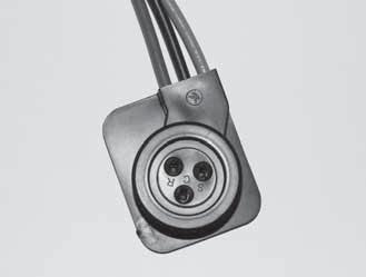
30 A-N Verifying Capacitor First, remove the power to the unit and allow 5-10 minutes for the capacitor to discharge. After discharge, remove two wires from capacity. Read UF on side and verify with volt meter that can read UF. It will also show ± range for reading. te: Rating will change with different size units. A-O Checking Pump Power Cord Verify V on pump power cord. te: Before removing cord from pump, verify that power is turned off on unit or pump will be damaged! Green White Black te: Thermostat/service tool display may still show watts even if one leg of power to the pump (110V) is not functioning. This can result in LT1 faults in heating and high pressure faults in cooling. Check v here 30 Geothermal Heat Pump Systems

31 Replacing Variable-Speed Pump Power Head 1) You can remove power head from motor with # 25 Torx driver if feedback is out of range. A-P 2) Remove plastic cover to remove Torx head screws. Comp verify voltage V Verifying Power at Molded Plug For Compressor A-Q 31

32 A-R 1) Place hydrometer in antifreeze. 2) Read hydrometer where water hits hydrometer. 3) Compare hydrometer to the charts below. Example: 15 F Methanol =.9825 specifi c gravity Verifying Antifreeze Read here Methanol Specific Gravity Chart Specific Gravity F -40 F -30 F -20 F -10 F 0 F 10 F 20 F 30 F 40 F 50 F C C C C -1.1 C 10 C -40 C C C -6.7 C 4.4 C Low Temperature Protection Ethanol Specific Gravity Chart F 0 F 5 F 10 F 15 F 20 F 25 F 30 F 35 F C C C C -9.4 C -6.7 C -3.9 C -1.1 C 1.7 C Propylene Glycol Specific Gravity Chart 1.07 Specific Gravity F -30 F -20 F -10 F 0 F 10 F 20 F 30 F 40 F -40 C C C C C C -6.7 C -1.1 C 4.4 C Low Temperature Protection 32 Geothermal Heat Pump Systems Low Temperature Protection
 When rectifi er")
 Perform an amp draw and read the amps.")


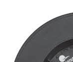
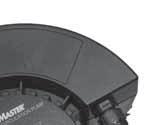
33 1) Remove rectifi er. Second Stage Verification 2) When rectifi er is removed, verify that pins are not bent. A-S 3) Perform an amp draw and read the amps. Then remove rectifi er. Amp draw should go down. If there is no change in amps, then the compressor is not shifting. 4) With the rectifi er removed from the compressor, verify VDC VDC 33


34 A-T Verifying 24V at Reversing Valve Verify 24V at reversing valve when calling for cooling To check the solenoid s magnetic pull, begin by pulling solenoid off of reversing valve. Then energize solenoid and place a metal screw driver in solenoid. You should feel the screw driver being pulled by the magnetic fi eld. A-U Checking Reversing Valve at DXM Volts AC 12 RV Relay 1 Comp Relay LP LP LT1 LT1 LT2 LT2 RV RV CO CO P7 24Vdc EH1 EH2 P6 CCG CC JW3 4 n CCH Relay P10 P9 T5 T6 T T3 T4 T4 T5 34 Geothermal Heat Pump Systems
 18-31.")


35 A0-2 Jumper A-V LT1 LT1 LT2 LT2 JW3 RV RV Off On CO CO 12 P7 Checking for Power at DXM2 A-W P1 RV Relay Y1 Y2 W O G R C AL1 AL2 R NSB C ESD OVR H A 24Vdc 1) V A/C. Verify proper voltage to the board. Alarm Relay C R JW1 Fault P2 1 CCH Relay EH1 EH2 P6 4 S2 A0-1 A0-2 Comp Relay CCG CC P10 P9 T2 T2 T3 T3 T4 T4 T5 T5 T6 T6 For Mod Valve IOV PWM For Pump A0-2 Jumper Location n Off On S1 Gnd T1 IOV PWM Gnd B- A Off On 2) If there is no 24V at DXM2, verify that the breaker is not tripped on the transformer. Ensure that the power supply to your transformer is using correct Tap (208/230). Blue Yellow Red 208 Orange 230 Black Common 35


36 A-X Verifying DC Voltage on DXM2 Board for Modulating Valve Check Off On OVR H A Off On S3 P3 A Acc1 Relay R NO1 NC1 COM S1 Acc2 Relay Factory Use NO2 NC2 COM R P11 Gnd T1 T2 COH COM AO2 AO1 Gnd White You should see Volts A/C D/C when valve is functioning properly. The voltage relates to the valve position: Valve 0% Open = 3.30 VDC Valve 50% Open = 5.00 VDC Valve 100% Open = VDC Valve gets 24 AC volts here. te: This check is the output to the valve from the DXM2. Red Black 36 Geothermal Heat Pump Systems


37 TXV Bulb Test A-Y Pressure Gauge Suction pressure increases when warmed and decreases when bulb is cooled in cup of ice water 37


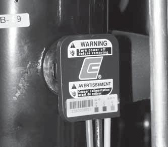
38 A-Z Verifying Dipswitch Position Relay Status Fault Off On C ESD OVR H A JW3 Off On Off On S3 P3 CCH Relay S2 A0-1 A Acc1 Relay R NO1 NC1 COM S1 Acc2 Relay Factory Use NO2 NC2 COM R P10 P11 T2 T2 T3 T3 T4 T4 Gnd T1 COH COM AO2 AO1 Gnd Dip switch #1 in On Position for Communicating B-A Replacing High Pressure Water Switch One of two high pressure water switches set to 145 PSI. te: If you are replacing a high pressure water switch, you can simply screw them off. However, beware that there is no Schrader core. To prevent water escaping when you remove the high pressure water switch, isolate the loop using flush valves in units with variable-speed pumps. To isolate the loop in units with modulating valves, use exterior ball valves. 38 Geothermal Heat Pump Systems
")


")
39 Verifying a Thermistor B-B 1) Clamp on digital to read ref next to LT1 to verify sensor 2) Remove this Molex plug to check resistance of the FP1/ LT1 sensor 3) Clamp on the meter close to the sensor location 4) Temperature reading 5) Resistance reading 39
40 B-B Verifying a Thermistor Thermistor Temperature Sensors The thermistors used with the DXM2 are NTC (negative temperature coeffi cient) type. Table 7 shows the replacement part numbers for the LT1 and LT2 thermistors. The sensors have a 1% tolerance and follow the characteristics shown in 1% Sensor Calibration Points Table. The minal resistance at various temperatures Table shows the nominal resistance at any given temperature and can be used for fi eld service reference. The sensor will use a minimum of 24 awg wire. 1% Sensor Calibration Points Table Temp ( F) Minimum Resistance (Ohm) Maximum Resistance (Ohm) minal Resistance (Ohm) Example: See images 4 and 5 on previous page. If your temperature reading is 71.2 with ohms, your sensor is good. All thermistors in Tranquility units can use this chart for verifi cation 40 Geothermal Heat Pump Systems minal resistance at various temperatures Table Temp (ºC) Temp (ºF) Resistance Resistance Temp (ºC) Temp (ºF) (kohm) (kohm)
41 Turning Breaker on in Panel or Auxiliary Heat Control B-C P2 P ON OFF L4 L3 ON OFF L2 L V With the blower at full load air speed, take a reading from the Digital Manameter. Check the reading against the IOM blower tables or in the tables shown below to determine the maximum external static pressure. Supply Air Static Pressure Check Static Pressure Probe inserted into 1/2 Hole B-D Verify that all grilles and registers are open and free. Use a Magnetic Static Pressure Tip tool (far right) to check the static pressure. Return Air Digital Manameter Magnetic Static Pressure Tip ECM Blower Performance Static Pressure Tables Tranquility 30 (TE) Series Airflow in CFM with wet coil and clean air fi lter Max Model ESP (in. wg) Airflow is controlled within 5% up to the Max ESP shown with wet coil. Tranquility 22 (TZ) Series Airflow in CFM with wet coil and clean air filter Model Max ESP (in. wg) Airflow is controlled within 5% up to the Max ESP shown with wet coil. Factory shipped on default CFM. 41


42 B-E Locating Thermostat Version and DXM2 Version INSTALLER SETTINGS THERMOSTAT CONFIG SYSTEM CONFIG ACCESSORY CONFIG INPUT DEALER INFO HUMIDITY CONFIG TEMPERATURE CONTROL DEMAND REDUCTION CNFG SERVICE MODE RESTORY DEFAULTS DXM2 3.3 ATC32U02 C 1.0 SELECT OPTION PREVIOUS Locate the version level of the DXM2 board and thermostat or service tool on the screen. You can locate the part number on the board and compare it to the table below. te: In the future, if there are software changes, the part number will also change. Program History of DXM2 Part Number / Dots Version Number 17B002N10 Version B0002N06 17B0002N05 17B0002N02 Version 1.2 with 3 Yellow Dots 2 Yellow Dots 1 Yellow Dot Version Gray Dots Version Gray Dots Version Gray Dot Dots Shows up as nothing B-F UltraCheck - EZ Motor Diagnostic Tool 42 Geothermal Heat Pump Systems


43 Verify that dipswitch number 1 is in the On position. If dipswitch number 1 is in the Off position, the thermostat will not function. Checking Dipswitches on DXM2 B-G Under most residential situations, dipswitch banks 1 and 2 will all be in the On position. If any of these dipswitches need to be switched to Off, consult the DXM2 AOM (97B0003N15). Magnet Test to Shift Reversing Valve into Cooling Use a magnet to pull the internal slide to one side or another. B-H Discharge line Strong magnet placed on air coil side Line to air coil Line to compressor (suction) Line to coax 43


44 B-I Checking Blower Line Voltage V B-J For a Modulating Valve that Loses Configuration on Thermostat In order to have your thermostat acknowledge that the unit has a modulating valve instead of incorrectly showing a variable-speed pump, connect a piece of thermostat wire between GND and T1 so the DXM2 board does not see feedback. P2 Micro U1 JW1 Alarm Relay Status Fault Off On AL2 R NSB C ESD OVR H A Off On Off On S3 P3 S2 A0-1 A Acc1 Relay R NO1 NC1 COM S1 Acc2 Relay Factory Use NO2 NC2 COM R P10 P11 T2 T2 T3 T3 Gnd T1 COH COM AO2 AO1 Gnd 44 Geothermal Heat Pump Systems


45 Use a thermostat wire to connect TP2 and TP3 on the thermostat board. Hard Reset of Thermostat B-K 45
46 B-L Units Having LT1 Lockouts In Heating with Modulating Valve When running unit in Y1 and Y2, if valve position moves slightly below 50% open, there is a greater impact on GPM. Putting a pressure-reducing valve ahead of heat pump will prevent valve from moving below 50% open. Set pressure reducing valve to 30 PSI. Shut Off Ball Valves for Isolation Well Tank Water Out Water In Boiler Drains Pressure- Reducing Valve - 30 PSI PSI Typical Household Pressure for Wells 46 Geothermal Heat Pump Systems
47 Definitions of Conditions CONTACTOR OPEN - NOT BUZZING When the contactor is open but not buzzing, it is an indication of no voltage to its coil, or that there is voltage to its coil but the coil is open circulated. If unit does not start, check voltage at coil with volt meter. If there is voltage, the coil is open circulated. Replace the contactor. If no voltage, check power to control circuit. LOW SUCTION PRESSURE If low suction pressure is suspected, switch to heating mode and check the suction pressure. This suction pressure should not be lower than the refrigerant pressure equivalent to entering water temperature minus 40 F, provided there is adequate water fl ow and entering air is approximately at 70 F. OPEN HIGH PRESSURE SWITCH It is factory set to shut down the unit at 600 PSI. EXCESSIVE DISCHARGE PRESSURE If excessive discharge pressure is suspected, switch to heating mode and check the discharge pressure. This discharge pressure should not be higher than the refrigerant pressure equivalent to entering air dry bulb temperature plus 60 F, provided there is proper air flow and entering water temperature is approximately at 70 F. COMPRESSOR OVERLOADS OPEN AND CLOSE The purpose of overloads is to quickly sense excessive compressor current and/or temperature and open the power circuit to prevent burnout of motor. This condition may be caused by repeated call to start before pressures equalize, low voltage, tightness of new compressor, excessive current draw or the temperature of the suction gas being too warm to adequately cool the motor. Warm suction gas may be due to an under charge, too much superheat, restriction in liquid or suction line, or restriction in capillary. When the overload opens, it may take from 5 to 30 minutes for it to cool suffi - ciently to close. CONTACTOR OPEN - BUZZING When the contactor is open but buzzing, it is an indication that its coil is energized but the contactor is unable to close. NORMAL VOLTAGE TO COIL Check voltage to coil. It should not be lower than 10% below rated voltage as the contractor tries to close. If voltage is normal, the mechanism may be tight or fouled. Remove and inspect mechanism. Clean if necessary. If too sluggish, replace contactor. BELOW NORMAL VOLTAGE TO COIL Check voltage to coil. If it is lower than 10% below rated voltage, it is probably due to low supply voltage, faulty transformer or phase loss. OPEN OVERLOAD SWITCH Sometimes overloads will fail with contacts in the open position, or contacts may be closed but not conducting electrically. To check this, disconnect power circuit. If unit starts, replace overload if it is located in the electrical box. If unit does not start, the trouble is elsewhere. BURNED CONTACTS Sometimes contacts will close mechanically but will not conduct electrically. To check for this, disconnect power circuit and measure contact resistance with ohmmeter. The meter should read zero ohms. If meter does not read zero ohms, replace contactor. If ohmmeter is not available, disconnect power circuit, place temporary jumpers from line side of contacts and close power circuit. If unit starts, replace contactor. If unit does not start, trouble is elsewhere. Burned contacts may also cause high current draw. EXPANSION VALVE BULB LOST CHARGE If the bulb of the expansion valve loses its charge, there will be no pressure to open the valve, thus causing low suction pressure. To check this, remove expansion valve bulb from suction line and hold it in your hand. If the suction pressure does not increase in a few minutes and there are no restrictions in the refrigerant circuit, it is an indication that the bulb has lost its charge. Replace expansion valve. DISTRIBUTOR TUBE RESTRICTED To check this, check suction pressure (very low suction pressure is an indication of restriction or excessive under charge) on cooling cycle temporarily cut off air to air coil and allow unit to operate. If there is a partial restriction or excessive undercharge, frost will occur at that point. If there is no restriction, the evaporator coil will frost uniformly. If there is a total restriction anywhere in the refrigerant circuit from the condenser through the evaporator and back to the compressor, there will be no frost, the suction pressure may go into vacuum and the discharge pressure will correspond to approximately ambient temperature because there will be no vapor to compress. EXCESSIVE SUPERHEAT Superheat is the temperature of the refrigerant vapor above the temperature corresponding to the vapor pressure. It should be 3 to 25 F. Excessive superheat is an indication that the evaporator is starved. That is, not enough liquid refrigerant in the coil. Excessive superheat may be due to undercharge, restriction in refrigerant circuit, low discharge pressure, expansion valve bulb lost charge, too much load on evaporator, or refrigerant flashing ahead of expansion valve or capillary due to pressure drop. HIGH AMPS Refer to nameplate on unit. Amps should not exceed rating more than 10%. A-Y A-H POOR EXPANSION VALVE BULB INSTALLATION The expansion valve bulb should be securely mounted and properly located on clean pipe, parallel to pipe with fi rm metal contact and wrapped with insulation tape to assure proper sensing of suction line temperature. 47
BasicTroubleshooting Information and Guidelines
 BasicTroubleshooting Information and Guidelines BasicTroubleshooting Information and Guidelines Information and Guidelines May 2017 BasicTroubleshooting PRIOR TO CONTACTING CLIMATEMASTER TECHNICAL SUPPORT,
Table of Contents. Service Procedures. Service Procedures. Measuring Superheat (4) Measuring Subcooling (5) Airflow Calculation (6-8)
 Measuring Subcooling (5) Airflow Calculation (6-8)") Table of Contents Refrigeration Cycle Service Procedures Measuring Superheat (4) Measuring Subcooling (5) Airflow Calculation (6-8) Solving Problems Identifying Low System Charge (9-11) Identifying High
Table of Contents Refrigeration Cycle Service Procedures Measuring Superheat (4) Measuring Subcooling (5) Airflow Calculation (6-8) Solving Problems Identifying Low System Charge (9-11) Identifying High
ACDU02 Communicating Service Tool
 ACDU02 Communicating Service Tool Operation Manual 97B0106N01 Rev.: 4/17/14 Caution: These instructions are intended to be used by the installer or service personnel. End users are NOT advised to change
Tranquility Digital Quick Start Guide
 Tranquility Digital Quick Start Guide 97B0107N01 Residential Packaged and Split DIGITAL Geothermal Heat Pumps With igate and vflow Technology B Step Title Page 1 Thermostat Confi guration 3 Staging 3 Auxiliary
Tranquility Digital Quick Start Guide
 Tranquility Digital Quick Start Guide 97B0107N01 Residential Packaged and Split DIGITAL Geothermal Heat Pumps With igate and vflow Technology Rev.: January 25, 2016 Step Title Page 1 Thermostat Confi guration
DXM2 Digital Heat Pump Controller
 APPLICATION, OPERATION & MAINTENANCE MANUAL DM2 Digital Heat Pump Controller Heat Controller, Inc. 1900 Wellworth Ave. Jackson, MI 49203 (517)787-2100 www.heatcontroller.com Application, Operation, & Maintenance
UNIT DIGITAL CONTROLS APPLICATION, OPERATION & MAINTENANCE
 DM2 Digital Heat Pump Controller Rev: 3 November 2017 DM2 Overview 3 Physical Dimensions and Layout 4 Layout and Connections 5 Field Selectable Inputs 6 Safety Features 8 Unit Operation Description 10
ATC32U02 igate Communicating, Programmable Thermostat
 ATC32U02 igate Communicating, Programmable Thermostat Installation Manual 97B0055N03 Rev.: 2/24/14 Caution: These instructions are intended to be used by the installer or service personnel. End users are
ATC32U01A Communicating, Programmable Thermostat
 ATC32U01A Communicating, Programmable Thermostat Installation Manual 97B0055N07 Created: 10/1/12 Caution: These instructions are intended to be used by the installer or service personnel. End users are
ATC32U01 igate Communicating, Programmable Thermostat
 ATC32U01 igate Communicating, Programmable Thermostat Installation Manual 97B0055N03 Rev.: 2/4/13 Caution: These instructions are intended to be used by the installer or service personnel. End users are
SECTION 7 AIR CONDITIONING (COOLING) UNIT 41 TROUBLESHOOTING
 UNIT 41 TROUBLESHOOTING") SECTION 7 AIR CONDITIONING (COOLING) UNIT 41 TROUBLESHOOTING UNIT OBJECTIVES After studying this unit, the reader should be able to Select the correct instruments for checking an air conditioning unit
SECTION 7 AIR CONDITIONING (COOLING) UNIT 41 TROUBLESHOOTING UNIT OBJECTIVES After studying this unit, the reader should be able to Select the correct instruments for checking an air conditioning unit
Refrigeration/Troubleshooting Manual
 Refrigeration/Troubleshooting Manual P.O. Box 245 Syracuse, NY 13211 www.roth-america.com 888-266-7684 P/N: 2300100910 Table of Contents: Section 1: Geothermal Refrigeration Circuits Overview... 2 Water-to-Air
DXM CONTROLS. DXM Digital Heat Pump Controllers. Application, Operation, & Maintenance. Table of Contents
 Table of Contents DXM CONTROLS DXM Electronic Controls Features Comparison 2 DXM Electronic Heat Pump Controls 3 DXM Physical Dimensions & Layout 4 DXM Controls 5 DXM Service & Application Notes 13 Troubleshooting
For an administrative fee of $9.97, you can get an un-locked, printable version of this book.
 The System Evaluation Manual and Chiller Evaluation Manual have been revised and combined into this new book; the Air Conditioning and Refrigeration System Evaluation Guide. For an administrative fee of
SERVICING PROCEDURE R-410A LEAK TEST EVACUATION CHARGING. Bard Manufacturing Company, Inc. Bryan, Ohio Manual Page 1 of 11
 SERVICING PROCEDURE R-410A LEAK TEST EVACUATION CHARGING Bard Manufacturing Company, Inc. Bryan, Ohio 43506 Since 1914...Moving ahead, just as planned. Manual No.: 2100-479 Supersedes: NEW File: Volume
Instructors: Contact information. Don Reynolds Doug McGee Factory Tech Support
 Contact information Instructors: Don Reynolds 616-560-9903 Doug McGee 517-294-3932 Factory Tech Support 888-593-9988 Product Improvements for 2017 Todays Objectives Job Site Information Sheets Low Ambient
CXM/DXM. Application, Operation & Maintenance Instructions 97B0003N08 Revision: 01/10/05. CXM/DXM Digital Heat Pump Controllers.
 CXM/DXM CXM/DXM Digital Heat Pump Controllers Application, Operation & Maintenance Instructions 97B0003N08 Revision: 01/10/05 Table of Contents CXM / DXM Control Features Comparison 2 Part I - CXM Control
Electrical Problems. Fuse(s) blow or circuit breaker trips. Does the unit use circuit breakers or fuses? Replace with correct fuse(s)
 blow or circuit breaker trips. Does the unit use circuit breakers or fuses? Replace with correct fuse(s)") Electrical Problems Fuse(s) blow or circuit breaker trips Does the unit use circuit breakers or fuses? Fuse(s) Circuit breakers Are the fuses dual element time delay? Is the circuit breaker HACR rated?
Electrical Problems Fuse(s) blow or circuit breaker trips Does the unit use circuit breakers or fuses? Fuse(s) Circuit breakers Are the fuses dual element time delay? Is the circuit breaker HACR rated?
Otherwise, you can continue reading the file on the following pages.
 If you d like to be able to print this file out to study off-line or use on the job, a printable version is available for an administrative fee of $3.97 USD. To download the unlocked file, click here.
Calhoon MEBA Engineering School. Study Guide for Proficiency Testing Refrigeration
 Calhoon MEBA Engineering School Study Guide for Proficiency Testing Refrigeration 1. To prevent an injury when working with refrigerants, what safety precautions are necessary? 2. When halogens are in
ClimaDry II. Table of Contents. ClimaDry II Whole House Dehumidification Option. Tranquility 30 Tranquility 20
 ClimaDry II ClimaDry II Whole House Dehumidification Option Tranquility 30 Tranquility 20 Applications Guide 97B0051N01 Revision: 10 Feb., 2016 Table of Contents Model Nomenclature Example 3 ClimaDry Overview
Q - Series Boiler. Troubleshooting Manual
 Q - Series Boiler Troubleshooting Manual WARNING There are a number of live tests that are required when fault finding this product. Extreme care should be used at all times to avoid contact with energized
SERVICING S-15 CHECKING CAPACITOR
 S-15 CHECKING CAPACITOR The direct drive motors are of the permanent split capacitor design. A run capacitor is wired across the auxiliary and a portion of the main windings. The capacitors primary function
The Saturation process
 SOUTH METROPOLITAN TAFE WA The Saturation process Dennis Kenworthy 8/5/2016 A student study guide to measuring and interpreting the saturation process of refrigeration and air-conditioning equipment System
TROUBLESHOOTING GENERAL TROUBLESHOOTING PROBLEM PROBABLE CAUSE CORRECTIVE ACTION
 GENERAL TROUBLESHOOTING Compressor Conditioning system OFF Turn ON conditioning system will not run No electrical power Check fuses Wrong voltage to applied to unit Compressor internal overload tripped
Warm Case Troubleshooting Guide 9/18/2014
 Introduction Warm cases can be caused by various problems which require thorough troubleshooting. Begin the investigation with questions to store personnel asking for information such as when the last
User s Information and Installation Instructions
 Outdoor Air Conditioner User s Information and Installation Instructions 2-Stage R-410A Split System These units have been designed and tested for capacity & efficiency in accordance with A.H.R.I. Standards.
BASIC HEAT PUMP THEORY By: Lloyd A. Mullen By: Lloyd G. Williams Service Department, York Division, Borg-Warner Corporation
 INTRODUCTION In recent years air conditioning industry technology has advanced rapidly. An important byproduct of this growth has been development of the heat pump. Altogether too much mystery has surrounded
1025, BOUL. MARCEL-LAURIN INSTRUCTION MANUAL FOR WATER COOLED ENVIROCHILL CHILLER. Prepared par Claude Gadoury, P. Eng MTL TECHNOLOGIES INC.
 WYETH-AYERST CANADA INC. 1025, BOUL. MARCEL-LAURIN S T - L A U R E N T, Q U É B E C INSTRUCTION MANUAL FOR WATER COOLED ENVIROCHILL CHILLER MODEL P448800LT--55WC--22C66S Prepared par Claude Gadoury, P.
DOLE REFRIGERATING COMPANY 1420 Higgs Road Lewisburg, Tennessee Phone (931)
") DOLE REFRIGERATING COMPANY 1420 Higgs Road Lewisburg, Tennessee 37091 Phone (931) 359-6211 1-800-251-8990 www.doleref.com PHO WATER DEFROST OPERATION & MAINTENANCE MANUAL June 2002 PHO WATER DEFROST Table
DOLE REFRIGERATING COMPANY 1420 Higgs Road Lewisburg, Tennessee 37091 Phone (931) 359-6211 1-800-251-8990 www.doleref.com PHO WATER DEFROST OPERATION & MAINTENANCE MANUAL June 2002 PHO WATER DEFROST Table
Condensing Unit Installation and Operating Instructions
 Bulletin WCU_O&I 01 June 2003 Condensing Unit Installation and Operating Instructions WCU Air Cooled Condensing Unit Table of Contents Section 1. Section 2. Section 3. Section 4. Section 5. Section 6.
INSTALLATION & OPERATING INSTRUCTIONS FOR CEILING MOUNT AIR HANDLERS AC SERIES
 C US INSTALLATION & OPERATING INSTRUCTIONS FOR CEILING MOUNT AIR HANDLERS AC SERIES Made in the USA by: Goodman Manufacturing Company, L.P. I0-240B 2550 North Loop West, Suite 400, Houston, TX 77092 www.goodmanmfg.com
UNDERCOUNTER LABORATORY REFRIGERATORS and FREEZERS Installation, Operation and Maintenance Instructions
 UNDERCOUNTER LABORATORY REFRIGERATORS and FREEZERS Installation, Operation and Maintenance Instructions INSPECTION When the equipment is received, all items should be carefully checked against the bill
SECTION 8 AIR SOURCE HEAT PUMPS UNIT 43 AIR SOURCE HEAT PUMPS
 SECTION 8 AIR SOURCE HEAT PUMPS UNIT 43 AIR SOURCE HEAT PUMPS UNIT OBJECTIVES After studying this unit, the reader should be able to Describe the operation of reverse-cycle refrigeration (heat pumps) Explain
Heat Pump Defrost Board Replacement Kit
 Bard Manufacturing Company, Inc. Bryan, Ohio 43506 8620-223 Heat Pump Defrost Board Replacement Kit KIT FEATURES This kit is made up of the current defrost control board 8201-129 and a new defrost sensor.
Prodigy Eclipse Cuber Technical Training
 Prodigy Eclipse Cuber Technical Training 600 800 1000 1200 1400 1800 2000 In This Presentation What Eclipse is Components and their functions Installation Operation Maintenance Service Diagnosis The Prodigy
Application and Installation Bulletin for Master-Bilt Refrigeration Superheat Controller Kit Assembly(A ), 120/208/240/1/60, R404A, LT/MT APPS
, 120/208/240/1/60, R404A, LT/MT APPS") Application and Installation Bulletin for Master-Bilt Refrigeration Superheat Controller Kit Assembly(A900-22007), 120/208/240/1/60, R404A, LT/MT APPS Introduction The superheat controller is designed
Application and Installation Bulletin for Master-Bilt Refrigeration Superheat Controller Kit Assembly(A900-22007), 120/208/240/1/60, R404A, LT/MT APPS Introduction The superheat controller is designed
USER S MANUAL AND INSTALLATION INSTRUCTIONS IMPORTANT
 USER S MANUAL AND INSTALLATION INSTRUCTIONS P3BD Series 13 SEER Single Package Air Conditioner IMPORTANT Read this owner information to become familiar with the capabilities and use of your appliance.
Full Range Systems. Mokon Troubleshooting Guide Model 311. Process/Water Loop. Problem Possible Cause Corrective Measure. Process pump will not start
 Mokon Troubleshooting Guide Model 311 Process pump will not start Process pump shuts down during operation Pump seal leak Tank overflows or will not fill on systems with autofill option (water makeup valve)
Richard Hiles ClimateMaster
 Minnesota Geothermal Heat Pump Association 2012 Properly Sizing Ground Source Heat Pump Systems Richard Hiles ClimateMaster Objective Properly Size and Select GSHP System for Low Operating Costs And Proper
Rev B, 9/2/2009. Kodiak Chiller Overview
 930-0001 Rev B, 9/2/2009 Kodiak Chiller Overview Presentation Outline Phone: 781-933-7300 Lytron Technical Support Contact Information 3 Introduction 4 Part I: Unpacking 5 Part II: Installation 7 Part
RSMSD Technical Guide
 RSMSD Technical Guide www.aaon.com AAON/WattMaster Controls Inc. 8500 NW River Park Drive Parkville, MO 64152 Toll Free Phone: 866-918-1100 PH: (816) 505-1100 FAX: (816) 505-1101 E-mail: mail@wattmaster.com
User s Information and Installation Instructions
 Outdoor Air Conditioner User s Information and Installation Instructions 13 SEER R-410A High Efficiency Split System These units have been designed and tested for capacity & efficiency in accordance with
Hoffman Controls 759-ECM. Installation & Operating Instructions. Introduction. Installation. Pre-Installation Information/ Instruction
 Hoffman Controls Installation & Operating Instructions Introduction CAUTION Failure to read and understand the accompanying instructions and diagrams prior to energizing the Controller may result in permanent
Product Information and Technical Guide
 Product Information and Technical Guide Side by Side and Top Mount Refrigerators July 2003 - December 2003 White-Westinghouse 5995540384 January 2004 TABLE OF CONTENTS Safe Servicing Practices ------------------------------------------------------------------------------------------
Heat Pump Water Heater. Table of Contents
 Table of Contents INTRODUCTION... 3 SAFETY... 3 Electrical... 3 R410a Refrigerant... 3 Scalding... 3 Flammable Vapors... 3 COMPONENT PARTS OF THE HEAT PUMP WATER HEATER... 4 TOOLS... 10 OPERATIONAL MODES...
KM-61BAH KM-101BAH KM-151BAH
 NO. M006-749 ISSUED: FEB. 18, 2008 REVISED: JUN. 12, 2008 HOSHIZAKI SELF-CONTAINED CRESCENT CUBER MODEL KM-61BAH KM-101BAH KM-151BAH SERVICE MANUAL IMPORTANT Only qualified service technicians should attempt
Part 3 Troubleshooting
 Part Troubleshooting What is in this part? This part contains the following chapters: Chapter See page Troubleshooting 2 Error Codes: Hydro-box 7 Error Codes: Outdoor Units Error Codes: System Malfunctions
AIR CONDITIONING. Carrier Corporation 2002 Cat. No
 AIR CONDITIONING Carrier Corporation 2002 Cat. No. 020-016 1. This refresher course covers topics contained in the AIR CONDITIONING specialty section of the North American Technician Excellence (NATE)
INSTALLATION INSTRUCTIONS
 INSTALLATION INSTRUCTIONS T CLASS TPA Series HEAT PUMPS 7.5 TO 10 TONS 506148 01 12/08 Litho U.S.A. RETAIN THESE INSTRUCTIONS FOR FUTURE REFERENCE IMPORTANT The Clean Air Act of 1990 bans the intentional
Aprilaire Dehumidifier Troubleshooting Manual Models 1830, 1850, 1870
 Aprilaire Dehumidifier Troubleshooting Manual Models 1830, 1850, 1870 Table of Contents Troubleshooting Diagnostic Codes... 2 E1... 2 E2, E3... 3 E4.4 E5, E6... 7 E7, E8... 8 E9.9 Verifying Capacity...
PARALLEL RACK SYSTEM INSTALLATION & OPERATIONS MANUAL With Master Rack Compressor Sequencer
 PARALLEL RACK SYSTEM INSTALLATION & OPERATIONS MANUAL With Master Rack Compressor Sequencer 5/16 Rev. A 57-02509 2 Contents INTRODUCTION... 4 WARNING LABELS AND SAFETY INSTRUCTIONS... 5 PS SERIES PARALLEL
CAH SERIES INSTALLATION & MAINTENANCE MODELS CAH CAH
 CAH SERIES INSTALLATION & MAINTENANCE MODELS CAH 33-44-50 CAH 49-54-70 CAH VARIABLE SPEED AIR HANDLERS DIMENSIONS... 3 TECHNICAL SPECS... 4 INSTALLATION DON TS... 5 INSTALLATION DO S... 6 FREEZE STAT REQUIRED
Hoshizaki America, Inc.
 Hoshizaki America, Inc. Stackable Crescent Cuber Models KM-1800SAH/3 KM-1800SWH/3 KM-1800SRH/3 A Superior Degree of Reliability SERVICE MANUAL www.hoshizaki.com Number: 73131 Issued: 11-11-2005 Revised:
Aprilaire Dehumidifier Troubleshooting Manual Models 1830 & 1850
 Aprilaire Dehumidifier Troubleshooting Manual Models 1830 & 1850 Table of Contents Troubleshooting Diagnostic Codes... 2 E1, E2... 2 E3, E4... 3 E5, E6 & E7... 7 E8... 8 E9 9 Verifying Capacity... 10 Water
IMPORTANT. HOSHIZAKI provides this manual primarily to assist qualified service technicians in the service and maintenance of the icemaker.
 73105 IMPORTANT Only qualified service technicians should attempt to service or maintain this icemaker. No service or maintenance should be undertaken until the technician has thoroughly read this Service
INSTALLATION INSTRUCTIONS
 INSTALLATION INSTRUCTIONS T CLASS TSA Series 6 to 20 Ton AIR CONDITIONERS 6 20 TONS 506147 01 06/11 Supersedes 3/11 Litho U.S.A. RETAIN THESE INSTRUCTIONS FOR FUTURE REFERENCE IMPORTANT The Clean Air Act
ATC32U03 igate Communicating, Programmable Thermostat
 ATC32U03 igate Communicating, Programmable Thermostat User Manual 97B0055N02 Rev.: 11/3/17 Table of Contents Section Title Page Menu Navigation Shortcuts 3 1.0 Operating Mode Selection 3 2.0 Temperature
Air Conditioning Operation and Troubleshooting Matt Dunham
 Air Conditioning Operation and Troubleshooting Matt Dunham Major Components (10 Minutes) Compressor heart of the system, causes refrigerant to flow by increasing the pressure of the refrigerant Metering
Service Step by Step Trouble-Shooting Check-List
 WARNING: Only Data Aire trained technician or experience technicians should be working on Data Aire Equipment. Protect yourself at all times and work safe. Date: Dates at the job site: From: to Job#: Serial#:
ENVIRONMENTAL CONTROL UNIT (ECU) PART NUMBER OPERATIONS AND MAINTENANCE MANUAL
 PART NUMBER OPERATIONS AND MAINTENANCE MANUAL") ENVIRONMENTAL CONTROL UNIT (ECU) PART NUMBER 2001829 OPERATIONS AND MAINTENANCE MANUAL Prepared by: 860 Douglas Way PO Box 530 Natural Bridge Station, VA 24579 1.0 SCOPE: This Operations and Maintenance
ENVIRONMENTAL CONTROL UNIT (ECU) PART NUMBER 2001829 OPERATIONS AND MAINTENANCE MANUAL Prepared by: 860 Douglas Way PO Box 530 Natural Bridge Station, VA 24579 1.0 SCOPE: This Operations and Maintenance
ATC32U01 igate Communicating, Programmable Thermostat
 ATC32U01 igate Communicating, Programmable Thermostat User Manual 97B0055N02 Rev.: 7/2/12 Table of Contents Section Title Page Menu Navigation Shortcuts 3 1.0 Operating Mode Selection 3 2.0 Temperature
Sporlan Valve Division Parker Hannifan/CIC Group
 www.parker.com/cic Sporlan Valve Division Parker Hannifan/CIC Group Matt McGrath, SW Regional Sales Manager Bob Dolan, Sales Engineer - Atlanta www.parker.com/cic Why Discuss TEVs Today? Expansion Valves
FOR SERVICE TECHNICIAN S USE ONLY
 F SERVICE TECHNICIAN S USE ONLY NOTE: This sheet contains important Technical Service Data. Tech Sheet Do Not Remove Or Destroy DANGER Electrical Shock Hazard Only authorized technicians should perform
Installation Manual for ETI AVS Series and NON-ETI Air Handlers with SC or SD Compressor Units and R-410A Refrigerant
 EarthLinked TXV Kit Installation Manual for ETI AVS Series and NON-ETI Air Handlers with SC or SD Compressor Units and R-410A Refrigerant CONTENTS PAGE Pre-Installation 3 Air Handler Conversion 4 System
EarthLinked SW Series Compressor Unit R-410A Quik-Start Instructions
 EarthLinked SW Series Compressor Unit R-410A Quik-Start Instructions CONTENTS PAGE Pre-Installation 3 Placement & Mechanical Information 4 System Application Options 10 Antifreeze Protection 14 Electrical
AE R1 October to 5 Ton ZPS*K6 Copeland Scroll Two-Stage Compressors
 October 2017 1.5 to 5 Ton ZPS*K6 Copeland Scroll Two-Stage Compressors Safety Safety Instructions... 2 Safety Icon Explanation... 2 Instructions Pertaining to Risk of Electrical Shock, Fire, or Injury
INSTALLATION INSTRUCTIONS
 INSTALLATION INSTRUCTIONS T CLASS TPA Series 7.5 AND 10 TON HEAT PUMPS 7.5 TO 10 TONS 506148 01 10/2011 Supersedes 06/11 Litho U.S.A. RETAIN THESE INSTRUCTIONS FOR FUTURE REFERENCE IMPORTANT The Clean
YCIV Hz & Hz
 YCIV 0590-1500 50Hz & 0157-0397 60Hz Start-up Checklist SERVICE POLICY & PROCEDURES Supersedes: Nothing Form 201.23-CL1 (309) Commissioning PREPARATION Commissioning of this unit should only be carried
Standard and CELDEK Evaporative Cooler Modules Installation, Operation, and Maintenance Manual
 Standard and CELDEK Evaporative Cooler Modules Installation, Operation, and Maintenance Manual Standard Evaporative Cooler CELDEK Evaporative Cooler RECEIVING AND INSPECTION Upon receiving unit, check
TECHNICAL GUIDE DESCRIPTION SPLIT-SYSTEM AIR-COOLED CONDENSING UNITS MODELS: HF-07 FEATURES B-0703
 TECHNICAL GUIDE SPLIT-SYSTEM AIR-COOLED CONDENSING UNITS MODELS: HF-07 DESCRIPTION These Sunline 2000 units are completely assembled, piped and wired at the factory to provide one-piece shipment and rigging.
WineZone Ceiling Mount Ductless Split 15
 WineZone Ceiling Mount Ductless Split 15 Requires an HVAC technician to install and charge with R-22 refrigerant. Easy to install. Unit plugs into wall outlet. Industrial grade unit for longer life. Indoor
ECM OPERATION MANUAL
 ECM OPERATION MANUAL FOR USE WITH MODEL: SINGLE STAGE OH6FA072DV4 OH8FA119DV5 OD6F/RA072DV5 OL6F/RA072DV5 2-STAGE OH6FX072DV4 OD6F/RX072DV5 OL6F/RX072DV5 : IF YOU DO NOT FOLLOW THE SAFETY PRECAUTIONS BELOW
Heat Reclaim. Benefits,Methods, & Troubleshooting By Dave Demma, Manager Supermarket Sales, Sporlan Division - Parker Hannifin Corporation
 Form 30-217 / January 2007 Heat Reclaim Benefits,Methods, & Troubleshooting By Dave Demma, Manager Supermarket Sales, Sporlan Division - Parker Hannifin Corporation While the vapor-compression cycle has
1 Specifications. 2 Operation. PHOENIX 300 Operation & Service Instructions. 2.1 Transporting the Phoenix. 2.2 Location
 Therma-Stor Products A Division of DEC International Box 8050 Madison, WI 53708 Toll Free 1-800-533-7533 Local 1-608-222-5301 PHOENIX 300 Operation & Service Instructions Table of Contents 1. Specifications...
Freightliner Refrigerator Troubleshooting Guide For (TJ18F) (TJ22F) (TJ18FP3)
 (TJ22F) (TJ18FP3)") www.dometic.com Freightliner Refrigerator Troubleshooting Guide For Before initiating troubleshooting, the following equipment is recommended: Multimeter, 20 gauge (min) wires to use as jumpers, and 12Vdc
www.dometic.com Freightliner Refrigerator Troubleshooting Guide For Before initiating troubleshooting, the following equipment is recommended: Multimeter, 20 gauge (min) wires to use as jumpers, and 12Vdc
Product Information and Technical Guide
 Product Information and Technical Guide Side by Side and Top Mount Refrigerators January 2004 - March 2004 White-Westinghouse 5995413308 July 2004 TABLE OF CONTENTS Safe Servicing Practices ------------------------------------------------------------------------------------------
HP50HA ABG Heat Pump
 HP50HA ABG Heat Pump Troubleshooting Guide Residential TSG-ABGHPa Copyright 2017 Hayward Industries Inc. Safety Precautions Warning! High Voltage Electrocution Hazard Hazardous voltage can shock, burn,
OPERATIONS AND MAINTENANCE MANUAL FOR THE 8-TON TURF CART ENVIRONMENTAL CONTROL UNIT (ECU) PART NUMBER
 PART NUMBER") OPERATIONS AND MAINTENANCE MANUAL FOR THE 8-TON TURF CART ENVIRONMENTAL CONTROL UNIT (ECU) PART NUMBER 2001927 Prepared by: 860 Douglas Way PO Box 530 Natural Bridge Station, VA 24579 1 1.0 SCOPE: This
OPERATIONS AND MAINTENANCE MANUAL FOR THE 8-TON TURF CART ENVIRONMENTAL CONTROL UNIT (ECU) PART NUMBER 2001927 Prepared by: 860 Douglas Way PO Box 530 Natural Bridge Station, VA 24579 1 1.0 SCOPE: This
CCH/CCW, VFC/VFW, MHC/MHW, LVC/LVW
 Operation & Maintenance Manual OM 931-6 Group: WSHP Part Number: 910157590 Date: September 2014 MicroTech III Unit Controller for Water Source Heat Pump Units Used with Enfinity Models CCH/CCW, VFC/VFW,
Troubleshooting & Reference
 Troubleshooting & Reference Error Code Descriptions Description of Error Codes - 9, 12 MBH code malfunction Error Display Repair Method 1 Storage slug (EEPROM) 2 Indoor PCB malfunction 3 Anti-freezing
OPERATION AND SERVICE for
 T-313 Manual OPERATION AND SERVICE for 68RM50-100/101 MICROMAX T-313 REV. 07/2012 2012 Mobile Climate Control SAFETY SUMMARY GENERAL SAFETY NOTICES The following general safety notices supplement the specific
Service Guide. Service Guide NATIONAL COMFORT PRODUCTS GAS & ELECTRIC MODELS. 2nd Edition
 2nd Edition Service Guide Thru-the-Wall Packaged Heating & Cooling Units Service Guide GAS & ELECTRIC MODELS NATIONAL COMFORT PRODUCTS HEATING & A/C EQUIPMENT National Comfort Products A Division of National
CONSOLIDATED TECHNOLOGY CORPORATION P.O. BOX 1537, OLIVE HILL, KY PHONE: (606) FAX: (606) ***** Safety *****
 FAX: (606) ***** Safety *****") SERVICE INSTRUCTION DEFROST CONTROL FIXED TIME INTERVAL S116 06,2000 SI-S116 CONSOLIDATED TECHLOGY CORPORATION P.O. BOX 1537, OLIVE HILL, KY 41 164 PHONE: (606) 286-5366 FAX: (606) 286-2700 ***** Safety
SERVICE INSTRUCTION DEFROST CONTROL FIXED TIME INTERVAL S116 06,2000 SI-S116 CONSOLIDATED TECHLOGY CORPORATION P.O. BOX 1537, OLIVE HILL, KY 41 164 PHONE: (606) 286-5366 FAX: (606) 286-2700 ***** Safety
Application, Operation and Maintenance Guide. DXM Electronic Heat Pump Control
 Application, Operation and Maintenance Guide DXM Electronic Heat Pump Control TABLE OF CONTENTS DXM Overview 3 Physical Dimensions and Layout 3 General Operating Parameters 4 Control Features 4 Field Selectable
Everything You. NEED to KNOW. TXV does this by keeping the coil supplied
 Everything You NEED to KNOW About TXVs } With the higher SEER air conditioners, technicians need to reacquaint themselves with thermostatic expansion valves B Y A L M A I E R Before the 13 SEER minimum
American Dish Service
 American Dish Service INSTALLATION INSTRUCTIONS Model JDS12 (T) or (R) Muffler Booster (T) 12kW, 240v, 3-ph, (R) 12kW, 208v, 3-ph Manufactured by Hubbell Electric Heater Company for use on American Dish
B-40/B-41 Modulating Temperature Controller
 INSTALLATION & OPERATING INSTRUCTIONS B-40/B-41 Modulating Temperature Controller For Raytherm Boilers & Water Heaters H2 514-4001 WH2 2100-4001 Catalog No. 5000.70 Effective: 12-21-11 Replaces: NEW P/N
CELDEK Evaporative Cooler Module Installation, Operation, and Maintenance Manual. CELDEK Evaporative Cooler
 CELDEK Evaporative Cooler Module Installation, Operation, and Maintenance Manual CELDEK Evaporative Cooler RECEIVING AND INSPECTION Upon receiving unit, check for any interior and exterior damage, and
4TTB3060D1000B 208/230/1/60 35 SCROLL /230/1/ /8
 Service Facts Split System Cooling 4TTB3048D1000B, 4TTB3060D1000B CAUTION IMPORTANT This document contains a wiring diagram, a parts list, and service information. This is customer property and is to remain
Trouble Shooting Guide PWA, 3-phase (D10571)
") Trouble Shooting Guide PWA, 3-phase (D10571) Trouble Shooting Guide Problem Possible Cause Possible Remedy Unit does not start Unit does not cool No power to unit, breaker tripped Low voltage Loose wire
Trouble Shooting Guide PWA, 3-phase (D10571) Trouble Shooting Guide Problem Possible Cause Possible Remedy Unit does not start Unit does not cool No power to unit, breaker tripped Low voltage Loose wire
Read and save these instructions
 Split Water-Cooled Central-Ducted Cooling System Operation Care Installation Manual CT14TSHWC CT13TSHWC CT12TSHWC CT34TSHWC CT1TSHWC www.apexwinecellars.com 17631 S Susana Road Rancho Dominguez, CA 90221
Series 9. Commissioning Checklist. MISSION CRITICAL Air Conditioning Systems. ClimateWorx International Inc.
 MISSION CRITICAL Air Conditioning Systems Series 9 Commissioning Checklist S9-CL2017.doc ClimateWorx International Inc. 14 Chelsea Lane, Brampton, Ontario, Canada L6T 3Y4 2 S9-CL2017.doc Commissioning
3.2 E1 Outdoor Unit PCB Abnormality E4 Actuation of Low Pressure Sensor E5 Compressor Motor Lock 3 52
 Error Codes: Outdoor Units Error Codes: Outdoor Units Part. What Is in This Chapter? Introduction Overview In the first stage of the troubleshooting sequence, it is important to correctly interpret the
INSTALLATION AND SERVICE OF WATER-SOURCE AND GEOTHERMAL HEAT PUMPS WaterFurnace International
 INTRODUCTION It is assumed that the reader has sufficient knowledge of the heat pump refrigeration cycle, and electrical knowledge, to understand heat pumps and their refrigeration and electrical circuits.
Bulletin (Jan 2011) And User s Guide
 And User s Guide") Bulletin 30 32 (Jan 2011) Unichiller Installation And User s Guide Customer Service If you have questions about Installation, operation and Maintenance of the Unichiller or would like to order replacement
Bulletin 30 32 (Jan 2011) Unichiller Installation And User s Guide Customer Service If you have questions about Installation, operation and Maintenance of the Unichiller or would like to order replacement
Norcold Repair Guide for Ice Maker
 Norcold Repair Guide for Ice Maker Section 10 Table of Contents Page: 10-2 General Description 10-2 Refrigerator Specifications 10-2 Refrigerator Operating Limits 10-2 Refrigerator Current Draws 10-2 Ice
Split Floor-Mounted Cooling System Operation Care Installation Manual
 Split Floor-Mounted Cooling System Operation Care Installation Manual CT14TSA CT13TSA CT12TSA CT34TSA CT1TSA CT14TSA-LA CT13TSA-LA CT12TSA-LA CT34TSA-LA CT1TSA-LA www.apexwinecellars.com Apex 17631 S Susana
EQUIPMENT PRE-STARTUP AND STARTUP CHECKLIST TEL NO: ORDER NO: CONTRACT NO:
 Supersedes: (316) Form QTC4-CL2 (617) MODEL QTC4 EQUIPMENT PRE-STARTUP AND STARTUP CHECKLIST CUSTOMER: ADDRESS: PHONE: JOB NAME: LOCATION: CUSTOMER ORDER NO: TEL NO: ORDER NO: CONTRACT NO: CHILLER MODEL
GTIP60 ISO GT Series, Inch Pounds - 60 Hz GT (iso) Spec Guide Drawings Spec Sheets Low Temp Heating P/T Charts
 Spec Guide Drawings Spec Sheets Low Temp Heating P/T Charts") GTIP60 ISO GT Series, Inch Pounds 60 Hz GT010070 (iso) Spec Guide Drawings Spec Sheets Low Temp Heating P/T Charts Rev: 903 Rev 1 Revisions: 31103 Changed HZ dwg to field convertible 5902 changed Unit
GTIP60 ISO GT Series, Inch Pounds 60 Hz GT010070 (iso) Spec Guide Drawings Spec Sheets Low Temp Heating P/T Charts Rev: 903 Rev 1 Revisions: 31103 Changed HZ dwg to field convertible 5902 changed Unit