Technical Manual MAY 2008 Edition
|
|
|
- Pamela Mathews
- 6 years ago
- Views:
Transcription
1 SPECIFICATION - GMP SERIES MULTI POSITION INDUCED DRAFT GAS FURNACE EARLY MODELS WITH HOT SURFACE IGNITION AND LATER MODELS WITH DIRECT SPARK IGNITION A.G.A. Approval No Technical Manual MAY 2008 Edition DISTRIBUTED BY AIR GROUP AUSTRALIA 28 Division Street Welshpool WA 6106 Telephone (08) Facsimile (08)
2 2
3 INDEX Page Specifications 4 Clearances from combustible surfaces 5 Cabinet details 5 Blower details 7-11 Ignition system Operation flow chart and fault analysis codes Flue Blower details 20 Location of safety controls 21 Wiring diagram and instructions - Thermostat 22 Indoor blower motor speeds 22 Wiring diagram - Hot Surface Ignition 23 Wiring diagram - Direct Spark Ignition Safety Instructions 26 3
4 SPECIFICATIONS GMP SERIES Australasian Distributor - Air Group Australia 28 Division Street Welshpool WA 6106 Phone (08) Fax: (08) Manufacturer - Goodman Manufacturing Company 1501 Seamist, Houston, Texas USA Gas Fired Forced Air Central Furnace Upflow, Downflow or Horizontal Position For Indoor Installation Only MODEL NUMBER GMP070 GMP110 GMP135 GMP150 GMP170 Gas Input Mj/Hr (Natural Gas) Gas Output Kw/Hr (Natural Gas) Gas Input Mj/Hr (LP Gas) Gas Output Kw/Hr (LP Gas) Temperature Rise - Deg. C Length - mm Width - mm Depth - mm Blower Motor - Amps FLA Blower Motor - H.P. 1/4 1/4 1/2 3/4 3/4 Flue Motor - Watts Flue Connection - mm Duct Connection - mm - Supply Air - Return Air Weight - Kg Air Quantity - L/s 100 Pa ESP High x 450 L/s 40 Pa ESP Low
5 CLEARANCES FROM COMBUSTIBLE MATERIALS - GMP SERIES 5
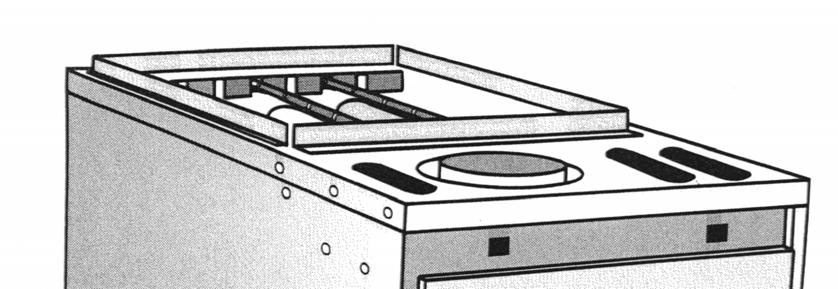
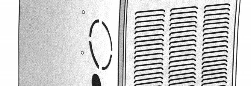
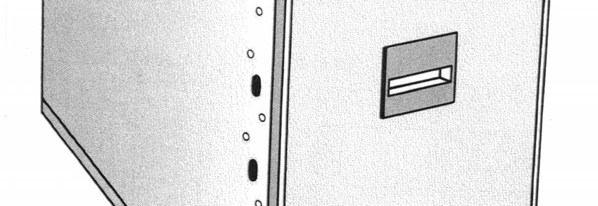
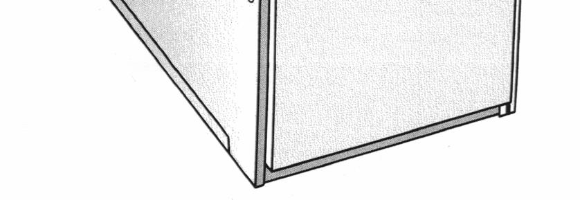
6 CABINET CONSTRUCTION - GMP SERIES ALL DIMENSIONS IN MILLIMETRES Cabinet Material - All Models = 0.66mm low carbon steel with baked enamel finish. Blower Deck Material - All Models = 1.067mm aluminized steel. Bottom Tie Plate - All Models = low carbon steel with baked enamel finish Heat Exchanger Support Rails - All Models = 0.864mm aluminized steel. Model Supply Air Flange * Return Air Opening * Cabinet Width A max. A min. B E D C GMP GMP GMP GMP GMP * Note... Supply and return air reverse orientation in downflow configuration. 6
7 GMP 070 BLOWER ASSEMBLY ALL DIMENSIONS IN MILLIMETRES MOTOR DATA BLOWER WHEEL DATA VOLTAGE / PH / Hz ROTATION (LEAD END) AMPS - FLA AMPS - LRA HORSEPOWER PART No. CAPACITOR (P/N B ) / 1 / 50 CCW /4 B µF/370V DIAMETER WIDTH QTY. OF BLADES PART No B COMPLETE BLOWER ASSEMBLY PART No S 7
8 GMP 110 BLOWER ASSEMBLY ALL DIMENSIONS IN MILLIMETRES MOTOR DATA BLOWER WHEEL DATA VOLTAGE / PH / Hz ROTATION (LEAD END) AMPS - FLA AMPS - LRA HORSEPOWER PART No. CAPACITOR (P/N B ) / 1 / 50 CCW /4 B µF/370V DIAMETER WIDTH QTY. OF BLADES PART No B COMPLETE BLOWER ASSEMBLY PART No S 8
9 GMP 135 BLOWER ASSEMBLY ALL DIMENSIONS IN MILLIMETRES MOTOR DATA BLOWER WHEEL DATA VOLTAGE / PH / Hz ROTATION (LEAD END) AMPS - FLA AMPS - LRA HORSEPOWER PART No. CAPACITOR (P/N B ) / 1 / 50 CCW /2 B µF/370V DIAMETER WIDTH QTY. OF BLADES PART No B COMPLETE BLOWER ASSEMBLY PART No S 9
10 GMP 150 BLOWER ASSEMBLY ALL DIMENSIONS IN MILLIMETRES MOTOR DATA VOLTAGE / PH / Hz ROTATION (LEAD END) AMPS - FLA AMPS - LRA HORSEPOWER PART No. CAPACITOR (P/N B ) / 1 / 50 CCW /4 B µF/370V BLOWER WHEEL DATA DIAMETER WIDTH QTY. OF BLADES PART No. COMPLETE BLOWER ASSEMBLY PART No S B
11 GMP 170 BLOWER ASSEMBLY ALL DIMENSIONS IN MILLIMETRES MOTOR DATA BLOWER WHEEL DATA (2 REQ D) VOLTAGE / PH / Hz ROTATION (LEAD END) AMPS - FLA AMPS - LRA HORSEPOWER PART No / 1 / 50 CCW /4 B COMPLETE BLOWER ASSEMBLY PART No S DIAMETER WIDTH QTY. OF BLADES PART No. LEFT PART No. RIGHT B B
 All dimensions in Millimetres 4) Two styles of valves are available, one with a Blue knob to isolate and another with a Toggle Switch. Both valves are compatible with all furnaces.")
12 GAS VALVE GMP IGNITION SYSTEM COMPONENTS - ALL MODELS Part No. B NOTES; 1) 24V, 50/60 Hz, 0.30 Amps. 2) Regulator is set at factory, but outlet gas pressure should be checked by gas fitter. 3) All dimensions in Millimetres 4) Two styles of valves are available, one with a Blue knob to isolate and another with a Toggle Switch. Both valves are compatible with all furnaces. 5) Gas Pressures KPa (Natural Gas) KPa (LPG) Old Style with Blue Isolator Knob New Style with Isolator Toggle Switch 12
 Supply Voltage: 220/240-1 - 50 Ignitor Voltage: 110V Tries for Ignition: 2 Gas Valve Voltage: 24V Igniter Heat Up Period: 17 seconds Used in")
13 GMP IGNITION SYSTEM COMPONENTS HOT SURFACE IGNITION 50 HZ HOT SURFACE MODULE - NO LONGER AVAILABLE Part No. B Ignition Type: Hot Surface Ignition (HSI) Supply Voltage: 220/ Ignitor Voltage: 110V Tries for Ignition: 2 Gas Valve Voltage: 24V Igniter Heat Up Period: 17 seconds Used in conjunction with the Timed Fan Control to operate the Igniter, Gas Valve and Safety Switches. 13
 Steady State Current: 4.25 to 4.75 Amps Warm Up Time ( to 980 o C ): 17 seconds Igniter Material: Recrystallized Silicone Carbide TIMED FAN CONTROL - NO LONGER AVAILABLE Part No.")
14 GMP IGNITION SYSTEM COMPONENTS HOT SURFACE IGNITION HOT SURFACE IGNITER - NO LONGER AVAILABLE Part No. B S Ignition Type: Hot Surface Ignition (HSI) Supply Voltage: 110V (138V Max.) Steady State Current: 4.25 to 4.75 Amps Warm Up Time ( to 980 o C ): 17 seconds Igniter Material: Recrystallized Silicone Carbide TIMED FAN CONTROL - NO LONGER AVAILABLE Part No. B Ignition Type: Hot Surface Ignition (HSI) Low Voltage Fuse Protection: 5 Amps Supply Voltage: 220/ Indoor Blower Off Delay: Selectable seconds, not adjustable. Used in conjunction with the Hot Surface Module to control the Flue Blower and Indoor Blower. 14


15 GMP IGNITION SYSTEM COMPONENTS - ALL MODELS DIRECT SPARK IGNITION DIRECT SPARK IGNITION MODULE - Part No. B No longer available Ignition Type: Direct Spark Ignition (DSI) Supply Voltage: 220/240 V Ignitor Voltage: 22KV open circuit Tries for Ignition: 2 Gas Valve Voltage: 24V Indoor Blower Off Delay: Selectable - 120, 135 and 150 seconds. Low Voltage Fuse Protection: 3 Amps VER B No longer available VER B VER B
16 GMP IGNITION SYSTEM COMPONENTS - ALL MODELS DIRECT SPARK IGNITION DIRECT SPARK IGNITOR Part No. B Ignitor Voltage: 22KV open circuit Connection: 6.4mm Quick Connect Spade Lead Length: 760mm FLAME SENSOR Part No. B Connection: 6.4mm Quick Connect Spade ALL DIMENSIONS IN MILLIMETRES 16
17 IGNITION SYSTEM SEQUENCE HOT SURFACE IGNITION 3 Note: If any of the safety circuit Opens the gas valve will immediately turn off until this condition resets. 17
18 Thermostat Calls for Heat Is the Pressure Switch Open YES Flue Blower is Energised Does the Pressure Switch Close YES Flue Blower Runs for 15 Seconds Pre-purge Period Gas Valve and Igniter are Energised NO NO Fault Code 3. Indefinite Lockout Until Pressure Switch Opens Fault Code 2. Flue Remains Running until Pressure Switch Closes FAULT ANALYSIS CODES DIRECT SPARK IGNITION A green LED is provided to indicate system faults as follows; Steady ON - Control OK. Steady OFF - Internal control fault or no power. 1 Flash - Lockout due to failed ignition or flame dropouts. 2 Flashes - Pressure switch is open with flue motor ON. 3 Flashes - Pressure switch is closed with flue motor OFF. 4 Flashes - Limit switch is open. 5 Flashes - Flame detected with gas valve closed. The flash rate is 0.25 seconds ON, 0.25 seconds OFF, with a 2.0 second pause between flash codes. OPERATION FLOW CHART 18
19 Is Flame Sensed by Flame Sensor? NO 30 Second Heat Exchanger Warm up Period Indoor Blower Starts on Heat Speed Thermostat s Call for Heat is Satisfied Gas Valve is De-energized Flue Blower Remains on for 29 Second Post-purge Indoor Blower is De-energised after the selected Blower Off Delay Time Control Goes into an Inter-purge 19
20 FLUE BLOWER - ALL MODELS Complete Assembly Part No. B MOTOR DATA BLOWER DATA Manufacturer: Fasco Diameter: 115 Voltage / Ph / Hz: / 1 / 50 Width: 33 Watts: 35 Qty. of Blades: 26 R.P.M.: 2600 Part No. B Material: Base - Ryton, GE Supec Collar - Stainless Steel FLUE CHIMNEY - ALL MODELS ALL DIMENSIONS IN MILLIMETRES 20
21 GMP LOCATION OF SAFETY SWITCHES - ALL MODELS MAIN LIMIT Location: Heat Exchanger Purpose: To prevent excessive outlet air temperatures Qty. Per Unit: One Model PART NUMBER TEMP o C ( o F) LENGTH mm GMP S 115 (240) 178 GMP S 71 (160) 178 GMP S 115 (240) 76 GMP S 115 (240) 178 GMP S 115 (240) 178 AUXILLIARY LIMIT Part No.: B Location: Blower Housing Temp: 49 o C (120 o F) Purpose: To prevent excessive filter temperatures Qty. Per Unit: One FLAME ROLL-OUT Part No.: B Location: Burner box and blower deck Temp: 177 o C (350 o F) Purpose: To terminate burner operation if flame roll-out is present Qty. Per Unit: Four AIR PRESSURE SWITCH Location:Top left of cabinet Purpose:To ensure correct operation of venting system Qty. Per Unit: One Model PART NUMBER GMP 070 B GMP 110 B GMP 135 B GMP 150 B GMP 170 B
22 GMP THERMOSTAT WIRING - all models TERMINAL BLOCK MOUNTED ON DOOR SWITCH COVER 24V ACTIVE - RED HEATING - WHITE BLANK FAN ONLY - GREEN FACTORY WIRING FIELD WIRING INDOOR BLOWER MOTOR SPEEDS In normal heating mode ( Red and White connected via the thermostat ), the HEAT terminal on the DSI circuit board is energised. Therefore the Indoor Blower will run on the speed tapping that is connected to the HEAT terminal. In Fan Only mode ( Red and Green connected via a switch ), the COOL terminal on the DSI circuit board is energised. Therefore the Indoor Blower will run on the speed tapping that is connected to the COOL terminal. The Neutral wire, (White, Purple or Yellow) from all indoor blower motors is connected to L2 on the circuit board. E.g., The GMP150 fan motor has 3 speeds, Low (Red), Medium (Blue or Orange), and High (Black). Connect the Black wire to HEAT terminal on the circuit board and the Red wire to COOL terminal. The Indoor Blower will run at High speed while heating and low speed while in fan only. The Blue or Orange wire is placed on one of the UNUSED terminals. Model Motor Speeds Speed Wire Colours Low Med High GMP Red XXX Black GMP Red XXX Black GMP Red XXX Black GMP Red Blue or Orange Black GMP Red Blue or Orange Black 22
23 GMP WIRING DIAGRAM - HOT SURFACE IGNITION PRE 1998 REPLACEMENT PARTS: CONVERSION KIT - SPTT204 NO LONGER AVAILABLE: B , B & B
24 GMP WIRING DIAGRAM - ALL MODELS DIRECT SPARK IGNITION MODULE B NO LONGER AVAILABLE MAIN LIMIT SWITCH WIRE COLOUR CODE BL - BLUE BR - BROWN Y - YELLOW P - PURPLE R - RED O - ORANGE W - WHITE G - GREEN BLK - BLACK G TRANSFORMER BL M FLUE BLOWER L2 GND COM GAS VALVE BLUE - COMMON GREEN - FAN ONLY WHITE - HEATING RED - 24V ACTIVE TERMINALS FOR THERMOSTAT WIRES ON DOOR SWITCH COVER IGNITOR PRESSURE SWITCH Y O O BL P R Y FS FLAME SENSOR BR BL SEE PAGE 22 FOR MOTOR ANALYSIS LED CONNECTION SEE FOLLOWING DETAILS PAGE FOR MOTOR CONNECTION DETAILS D1 L1 L1 UNUSED M HEAT COOL L2 L2 L2 INDOOR BLOWER BR BL BR MAINS IN BLK DOOR SWITCH P P P P AUX. LIMIT SWITCH ROLLOUT SWITCHES P 24
25 GMP WIRING DIAGRAM - DIRECT SPARK IGNITION VERSION RED BLUE EARTH MAIN DIRECT SPARK IGNITER N A TRANSFORMER ORANGE BROWN BROWN MAINS IN A N BLUE BLUE YELLOW AIR PRESSURE SWITCH YELLOW M C P GAS VALVE ORANGE BLUE B AUX LIMIT MAIN LIMIT SWITCH RED B L2 L2 L2 L2 UNUSED D1 HEAT RED PURPLE ROLLOUT SWITCHES AUX LIMIT YELLOW PURPLE RED WHITE L1 GREEN L1 FS BROWN BLUE M FLUE BURNER ~ COOL FLAME SENSOR ORANGE BROWN FS N MAIN BURNER RED BROWN BLACK M ~ WI831/
26 LIGHTING INSTRUCTIONS These instructions are also on the furnace. FOR YOUR SAFETY, READ BEFORE OPERATING If you do not follow these instructions exactly, a fire or explosion may result causing property damage, personal injury or loss of life. A. This appliance does not have a pilot. It is equipped with an ignition device which automatically lights the burners. Do not try to light the burners by hand. B. BEFORE OPERATING smell around the appliance area for gas. Be sure to smell next to the floor because some gas is heavier than air and will settle on the floor. WHAT TO DO IF YOU SMELL GAS Do not try to light any appliance. Do not touch any electric switch. Do not use any telephone in your building. Immediately call your supplier from a OPERATING INSTRUCTIONS 1. STOP!! Read the safety information above on this label. 2. Set the thermostat to the lowest setting. 3. Turn off all electric power to the furnace. 4. This appliance is equipped with an automatic ignition system which automatically lights the burners. Do not try to light the burners by hand. 5. Remove control access panel. 6. Move the gas control switch or knob to OFF. 1. Set the thermostat to it s lowest setting. 2. Turn off all electric power to the appliance if service is to be performed. 3. Remove control access panel. TO TURN OFF GAS TO APPLIANCE If you cannot reach your gas supplier, call the fire department. C. Use only your hand to move the gas control switch or knob. Never use tools. If the gas control switch or knob will not operate, don t try to repair it, call for a qualified service technician. Force or attempted repair may result in a fire or explosion. D. Do not use this appliance if any part has been under water. Immediately call a qualified service technician to inspect the appliance and to replace any part of the control system and any gas control which has been under water. 7. Wait five (5) minutes to clear out any gas. STOP! Follow B in the safety information above on this label. If you don t smell gas, go to the next step. 8. Move the gas control switch or knob to ON. 9. Replace control access panel. 10. Turn on all electric power to the furnace. 11. Set the thermostat to the desired setting. 12. If the appliance will not operate, follow the instructions To Turn Off Gas To Appliance and call your service technician or gas supplier. 4. Move the gas control switch or knob to OFF. Do not force. 5. Replace control access panel. FOR YOUR SAFETY Do not store or use petrol or other flammable liquids in the vicinity of this or any other appliance. WARNING: Improper installation, adjustment, alteration, service or maintenance can cause injury or property damage. Refer to the user s information manual provided with this furnace. For assistance or additional information consult a qualified installer, service agency or the gas supplier. This furnace must be installed in accordance with the manufacturers instructions and AG 601 Gas Installation Code COMMISSIONING INSTRUCTIONS Prior to initial startup open doors and windows as some non-toxic vapour and/or odour may be present. This is normal and these discharges will dissipate after running for a short time. 26

27 FM123/
USER S INFORMATION MANUAL
 USER S INFORMATION MANUAL UPFLOW/HORIZONTAL & DOWNFLOW TWO STAGE INDUCED DRAFT GAS FURNACES Recognize this symbol as an indication of Important Safety Information If the information in this manual is not
G60UH(X) WARNING. WARNING Sharp edges. Be careful when servicing unit to avoid sharp edges which may result in personal injury. Service Literature
 WARNING. WARNING Sharp edges. Be careful when servicing unit to avoid sharp edges which may result in personal injury. Service Literature") Service Literature Corp. 0204 L2 Revised 11 2006 G60UH(X) G60UH(X) SERIES UNITS G60UH(X) series units are mid efficiency gas furnaces used for upflow or horizontal applications only, manufactured with
Service Literature Corp. 0204 L2 Revised 11 2006 G60UH(X) G60UH(X) SERIES UNITS G60UH(X) series units are mid efficiency gas furnaces used for upflow or horizontal applications only, manufactured with
50M Integrated Single or Two-Stage HSI Integrated Furnace Control Kit INSTALLATION INSTRUCTIONS
 50M56-743 Integrated Single or Two-Stage HSI Integrated Furnace Control Kit INSTALLATION INSTRUCTIONS FAILURE TO READ AND FOLLOW ALL INSTRUCTIONS CAREFULLY BEFORE INSTALLING OR OPERATING THIS CONTROL COULD
GMSS92 / GCSS92. Single-Stage, Multi-Speed Gas Furnace Up to 92% AFUE. Heating Input: 40, ,000 BTU/h
 / Single-Stage, Multi-Speed Gas Furnace Up to 92% AFUE Heating Input: 40,000 120,000 BTU/h Contents Nomenclature...2 Product Specifications...3 Dimensions...5 Airflow Specifications...7 Wiring Diagram...10
GMSS96 / GCSS96 Single-Stage Multi-Speed Gas Furnace
 Heating Input: 40,000 120,000 BTU/h / Single-Stage Multi-Speed Gas Furnace up to 96% AFUE Standard Features Heavy-duty aluminized-steel tubular heat exchanger Stainless-steel secondary heat exchanger Single-stage
CAUTION WARNING. 50T Integrated Furnace Control INSTALLATION INSTRUCTIONS DESCRIPTION PRECAUTIONS
 50T35-743 Integrated Furnace Control INSTALLATION INSTRUCTIONS FAILURE TO READ AND FOLLOW ALL INSTRUCTIONS CAREFULLY BEFORE INSTALLING OR OPERATING THIS CONTROL COULD CAUSE PERSONAL INJURY AND/OR PROPERTY
GMSS92 / GCSS92. Single-Stage, Multi-Speed Gas Furnace Up to 92% AFUE. Heating Input: 40, ,000 BTU/h
 / Heating Input: 40,000 120,000 BTU/h Single-Stage, Multi-Speed Gas Furnace Up to 92% AFUE Contents Nomenclature...2 Product Specifications...3 Dimensions...5 flow Specifications...7 Wiring Diagram...10
GMSS96 / GCSS96. Single-Stage, Multi-Speed Gas Furnace Up to 96% AFUE. Heating Input: 40, ,000 BTU/h
 / Heating Input: 40,000 120,000 BTU/h Single-Stage, Multi-Speed Gas Furnace Up to 96% AFUE Contents Nomenclature...2 Product Specifications...3 Dimensions...5 flow Specifications...7 Wiring Diagram...10
DM80HE. Two-Stage Convertible Multi-Speed ECM Gas Furnace 80% AFUE. Heating Input: 60, ,000 BTU/h
 Two-Stage Convertible Multi-Speed ECM Gas Furnace 80% AFUE Heating Input: 60,000 100,000 BTU/h Contents Nomenclature... 2 Product Specifications... 3 Dimensions... 4 Airflow Data... 5 Wiring Diagram...
X341119P10 Gas Furnace Var. Speed Blower Var. Speed Inducer Two Stage Heat Direct Vent Models:
 Service Facts X349P0 Gas Furnace Var. Speed Blower Var. Speed Inducer Two Stage Heat Direct Vent Models: *UY060R9V3W *UY080R9V3W *UY00R9V4W *UY20R9V5W * First letter may be A or T *DY060R9V3W *DY080R9V3W
GAS UNITS KITS AND ACCESSORIES 505,172M 08/06
 2006 Lennox Industries Inc. Dallas, Texas, USA GAS UNITS KITS AND ACCESSORIES 505,172M 08/06 Litho U.S.A. IGNITION CONTROL REPLACEMENT KIT INSTALLATION INSTRUCTIONS FOR IGNITION CONTROL CONVERSION KIT
ADSH8. Two-Stage Convertible. Heating Input: 40, ,000 BTU/h
 ADSH8 Heating Input: 40,000 100,000 BTU/h Two-Stage Convertible Multi-Speed Gas Furnace 80% AFUE Standard Features Two-stage convertible gas valve automatically adjusts to high or low stage Durable SureStart
80% AFUE. Multi-Position, Dual$aver. Heating Input: 70, ,000 BTU/h
 Series 80% AFUE Multi-Position, Dual$aver Multi-Speed Gas Furnace Heating Input: 70,000 115,000 BTU/h Standard Features Dual-diameter tubular heat exchanger Two-stage gas valve that allows installer to
ZG Shown READ ALL INSTRUCTIONS IN THIS MANUAL AND RETAIN FOR FUTURE REFERENCE WARNING
 See unit nameplate for manufacturer and address. 507258-04 7/2018 Supersedes 10/2017 ZG 036, 048, 060, 072, 074 (3, 4, 5 and 6 Tons) ZG 092, 102, 120, 150 (7-1/2, 8-1/2, 10 and 12 Tons) ROOFTOP UNITS ZG
21D83M-843 Integrated Single Stage Furnace Control Replacement Kit INSTALLATION INSTRUCTIONS
 21D83M-843 Integrated Single Stage Furnace Control Replacement Kit INSTALLATION INSTRUCTIONS FAILURE TO READ AND FOLLOW ALL INSTRUCTIONS CAREFULLY BEFORE INSTALLING OR OPERATING THIS CONTROL COULD CAUSE
Operator: Save these instructions for future use!
 50A66-743 Integrated Furnace Control Operator: Save these instructions for future use! FAILURE TO READ AND FOLLOW ALL INSTRUCTIONS CAREFULLY BEFORE INSTALLING OR OPERATING THIS CONTROL COULD CAUSE PERSONAL
SERVICE FACTS WARNING M801-SF-1C. Gas Furnaces Upflow & Downflow Induced Draft 1 Stage Heat Models: DISCONNECT POWER BEFORE SERVICING M801P040AU24AA
 SERVICE FACTS Gas Furnaces Upflow & Downflow Induced Draft Stage Heat Models: M80P00AU2AA M80P060AU2AA M80P060AU36AA M80P080BU36AA M80P080BU8AA M80P00BU36AA M80P00CU8AA M80P00CU60AA M80PDU60AA M80P0DU60AA
KGA092 SHOWN READ ALL INSTRUCTIONS IN THIS MANUAL AND RETAIN FOR FUTURE REFERENCE WARNING
 See unit nameplate for manufacturer and address. 506380 01 11/2009 KGA024, 030, 036, 048, 060, 072 (2, 2 1/2, 3, 4, 5, and 6 Tons) KGA092, 102, 120, 150 (7 1/2, 8-1/2, 10, and 12 Tons) KGA180, 210, 240,
50A Integrated Furnace Control
 Goodman White-Rodgers 0130F00005 PCBBF110 PCBBF123 50A55-743 0130F00005S PCBBF110S PCBBF123S 50A55-289 B1809926 PCBBF112 50T55-289 B1809926S PCBBF112S 50A55-743 Integrated Furnace Control INSTALLATION
50M56U-843 Universal Single Stage HSI Integrated Furnace Control Kit INSTALLATION INSTRUCTIONS
 50M56U-843 Universal Single Stage HSI Integrated Furnace Control Kit INSTALLATION INSTRUCTIONS INSTALLER MUST READ PAGE 3 CONTAINS WIRING HARNESS AND BLOWER CONNECTION INSTRUCTIONS FOR ALL APPLICATIONS
KG 092 SHOWN READ ALL INSTRUCTIONS IN THIS MANUAL AND RETAIN FOR FUTURE REFERENCE WARNING
 See unit nameplate for manufacturer and address. 507350-03 3/2016 Supersedes 9/2015 KG 024, 030, 036, 048, 060, 072, 074, 090 (2, 2-1/2, 3, 4, 5, 6 and 7-1/2 Tons) KG 092, 102, 120, 150 (7-1/2, 8 1/2,
50A Integrated Furnace Control
 50A56-956 Integrated Furnace Control INSTALLATION INSTRUCTIONS FAILURE TO READ AND FOLLOW ALL INSTRUCTIONS CAREFULLY BEFORE INSTALLING OR OPERATING THIS CONTROL COULD CAUSE PERSONAL INJURY AND/OR PROPERTY
Operator: Save these instructions for future use!
 50V64-743 Integrated Furnace Control for Furnaces with Variable Fan Speed INSTALLATION INSTRUCTIONS Operator: Save these instructions for future use FAILURE TO READ AND FOLLOW ALL INSTRUCTIONS CAREFULLY
SERVICE AND INSTALLATION MANUAL MODELS HDO(H) OIL FOR YOUR SAFETY
 OIL FOR YOUR SAFETY") Bousquet Technologies Inc. 2121, Nobel, Ste Julie, Quebec, Canada, J3E1Z9 SERVICE AND INSTALLATION MANUAL MODELS HDO(H) OIL Oil-Fired air heater for industrial and commercial use. FOR YOUR SAFETY Do not
Bousquet Technologies Inc. 2121, Nobel, Ste Julie, Quebec, Canada, J3E1Z9 SERVICE AND INSTALLATION MANUAL MODELS HDO(H) OIL Oil-Fired air heater for industrial and commercial use. FOR YOUR SAFETY Do not
USER S INFORMATION MANUAL
 USER S INFORMATION MANUAL UPFLOW, DOWNFLOW, UPFLOW/HORIZONTAL & HORIZONTAL ONLY INDUCED DRAFT GAS FURNACES Recognize this symbol as an indication of Important Safety Information If the information in this
50M56U-843 INSTALLER MUST READ DESCRIPTION PRECAUTIONS WARNING CAUTION
 50M56U-843 Universal Single Stage HSI Integrated Furnace Control Kit INSTALLATION INSTRUCTIONS INSTALLER MUST READ PAGE 3 CONTAINS WIRING HARNESS AND BLOWER CONNECTION INSTRUCTIONS FOR ALL APPLICATIONS
TGA/KGA024, 030, 036, 048, 060, 072, 090 (2, 2 1/2, 3, 4, 5, 6, and 7 1/2 TONS)
") See unit nameplate for manufacturer and address. 506003 01 5/2009 Supersedes 1/2008 TGA/KGA024, 030, 036, 048, 060, 072, 090 (2, 2 1/2, 3, 4, 5, 6, and 7 1/2 TONS) TGA090, 102, 120, 150, TGA120 SHOWN (7
See unit nameplate for manufacturer and address. 506003 01 5/2009 Supersedes 1/2008 TGA/KGA024, 030, 036, 048, 060, 072, 090 (2, 2 1/2, 3, 4, 5, 6, and 7 1/2 TONS) TGA090, 102, 120, 150, TGA120 SHOWN (7
USER S INFORMATION MANUAL (2,4)SG13B
SG13B") USER S INFORMATION MANUAL (2,4)SG13B Series Gas Heating/Electric Cooling Package Unit Congratulations......your outdoor heating/cooling package unit is a valuable piece of equipment, designed and manufactured
USER S INFORMATION MANUAL (2,4)SG13B Series Gas Heating/Electric Cooling Package Unit Congratulations......your outdoor heating/cooling package unit is a valuable piece of equipment, designed and manufactured
Operator: Save these instructions for future use!
 031-01284-000/50A55-241 Integrated Furnace Control INSTALLATION INSTRUCTIONS Operator: Save these instructions for future use! FAILURE TO READ AND FOLLOW ALL INSTRUCTIONS CAREFULLY BEFORE INSTALLING OR
SERIES VAC Microprocessor-Based Direct Spark Ignition Control with Inducer Blower Relay FEATURES APPLICATIONS SPECIFICATIONS DESCRIPTION
 R SERIES 35-61 24 VAC Microprocessor-Based Direct Spark Ignition Control with Inducer Blower Relay F-35-61 August 2015 FEATURES Safe start with DETECT-A-FLAME flame sensing technology Custom pre-purge
Operator: Save these instructions for future use!
 21M51U-843 Universal Integrated Two-Stage 120Volt Hot Surface Ignition Control Kit INSTALLATION INSTRUCTIONS Operator: Save these instructions for future use! FAILURE TO READ AND FOLLOW ALL INSTRUCTIONS
G60UH(X) WARNING. WARNING Sharp edges. Be careful when servicing unit to avoid sharp edges which may result in personal injury. Service Literature
 WARNING. WARNING Sharp edges. Be careful when servicing unit to avoid sharp edges which may result in personal injury. Service Literature") Service Literature Corp. 0204 L2 Revised 09 2006 G60UH(X) G60UH(X) SERIES UNITS G60UH(X) series units are mid efficiency gas furnaces used for upflow or horizontal applications only, manufactured with
Service Literature Corp. 0204 L2 Revised 09 2006 G60UH(X) G60UH(X) SERIES UNITS G60UH(X) series units are mid efficiency gas furnaces used for upflow or horizontal applications only, manufactured with
Internet Version for Reference Only INDUCED DRAFT COMMERCIAL WATER HEATERS SUPPLEMENT INSTRUCTIONS TO PART #
 INDUCED DRAFT COMMERCIAL WATER HEATERS SUPPLEMENT INSTRUCTIONS TO PART #238-39387-00 THIS INSTRUCTION SUPPLEMENT IS ONLY INTENDED TO GIVE INSTALLATION INSTRUCTIONS AND INFORMATION RELATED TO THE INDUCED
G34M Bulletin #69/ August 2003
 ENGINEERING DATA G34M MULTI POSITION GAS FURNACE 12.4 to 31.0 kw Output 52.7 to 131.9 Mj Input 3.5 to 17.6 kw Nominal Add-on Cooling GAS FURNACES 50 Hz G34M Bulletin #69/490045 August 2003 Typical Applications
EL296UHV SERIES GAS FURNACE WARNING WARNING
 2011 Lennox Industries Inc. Dallas, Texas, USA 506769 01 08/2012 Supersedes 10/2011 EL296UHV SERIES GAS FURNACE Improper installation, adjustment, alteration, service or maintenance can cause property
EL195UHE SERIES GAS FURNACE WARNING WARNING
 2012 Lennox Industries Inc. Dallas, Texas, USA 506737-01 12/2012 Supersedes 06/2011 EL195UHE SERIES GAS FURNACE Improper installation, adjustment, alteration, service or maintenance can cause property
Bosch 80% AFUE Gas Furnace BGS80 Model
 Bosch 80% AFUE Gas Furnace BGS80 Model 4-Way Multipoise Category I Fan-Assisted Furnace User's Information Manual 3124627 2 Bosch 80% AFUE Gas Furnace User's Information Manual Data subject to change 06.2018
ML180UH SERIES GAS FURNACE WARNING WARNING
 2017 Lennox Industries Inc. Dallas, Texas, USA 506525-01 04/2017 Supersedes 10/2015 ML180UH SERIES GAS FURNACE Improper installation, adjustment, alteration, service or maintenance can cause property damage,
Packaged Gas/Electric Units. Owner s Guide to Operating and Maintaining Your Gas/Electric Unit
 Packaged Gas/Electric Units Owner s Guide to Operating and Maintaining Your Gas/Electric Unit ELECTRICAL SHOCK HAZARD. FIRE OR EXPLOSION HAZARD Disconnect power at fuse box or service panel before performing
EL195DFE SERIES GAS FURNACE WARNING
 2011 Lennox Industries Inc. Dallas, Texas, USA 506739 01 06/2011 EL195DFE SERIES GAS FURNACE Litho U.S.A. FIRE OR EXPLOSION HAZARD. Failure to follow safety warnings exactly could result in serious injury,
P.O. Box , Dallas, TX USER'S INFORMATION MANUAL Single-Stage Warm Air Gas Furnaces
 P.O. Box 799900, Dallas, TX 75379-9900 USER'S INFORMATION MANUAL Single-Stage Warm Air Gas Furnaces This is a safety alert symbol and should never be ignored. When you see this symbol on labels or in manuals,
Operator: Save these instructions for future use!
 WHITE-RODGERS 50A55-286 Integrated Furnace Control INSTALLATION INSTRUCTIONS Operator: Save these instructions for future use FAILURE TO READ AND FOLLOW ALL INSTRUCTIONS CAREFULLY BEFORE INSTALLING OR
M3RL Series TECHNICAL SPECIFICATIONS. FEATURES and BENEFITS. High Efficiency / Direct Vent Condensing Downflow Gas Furnace
 TECHNICAL SPECIFICATIONS M3RL Series High Efficiency / Direct Vent Condensing Downflow Gas Furnace Induced Draft - 90+ AFUE Input 60,000 & 80,000 Btuh The high efficiency downflow gas furnace is especially
EL195UH SERIES GAS FURNACE WARNING
 2010 Lennox Industries Inc. Dallas, Texas, USA 506597 01 11/2010 EL195UH SERIES GAS FURNACE Litho U.S.A. FIRE OR EXPLOSION HAZARD. Failure to follow safety warnings exactly could result in serious injury,
USER S INFORMATION MANUAL
 2005 Lennox Industries Inc. Dallas, Texas, USA USER S INFORMATION MANUAL 13GCSX SERIES UNITS GAS PACKAGED UNITS (2 5 TONS) Armstrong # 38152A068 505,058M 05/09 Supersedes 08/05 Table of Contents Litho
G60UHV(X) WARNING. WARNING Sharp edges. Be careful when servicing unit to avoid sharp edges which may result in personal injury. Service Literature
 WARNING. WARNING Sharp edges. Be careful when servicing unit to avoid sharp edges which may result in personal injury. Service Literature") Service Literature Corp. 0124 L11 Revised 11 2006 G60UHV(X) G60UHV(X) SERIES UNITS G60UHV(X) series units are mid efficiency gas furnaces used for upflow or horizontal applications only, manufactured with
Service Literature Corp. 0124 L11 Revised 11 2006 G60UHV(X) G60UHV(X) SERIES UNITS G60UHV(X) series units are mid efficiency gas furnaces used for upflow or horizontal applications only, manufactured with
G60DFV(X) WARNING. WARNING Sharp edges. Be careful when servicing unit to avoid sharp edges which may result in personal injury. Service Literature
 WARNING. WARNING Sharp edges. Be careful when servicing unit to avoid sharp edges which may result in personal injury. Service Literature") Service Literature Corp. 0211 L3 Revised 09 2006 G60DFV(X) G60DFV(X) SERIES UNITS G60DFV series units are mid efficiency gas furnaces used for downflow applications only, manufactured with Lennox Duralok
Service Literature Corp. 0211 L3 Revised 09 2006 G60DFV(X) G60DFV(X) SERIES UNITS G60DFV series units are mid efficiency gas furnaces used for downflow applications only, manufactured with Lennox Duralok
WARNING FIRE OR EXPLOSION HAZARD.
 2017 Lennox Industries Inc. Dallas, Texas, USA 506897-01 04/2017 Supersedes 10/2015 EL280DF SERIES GAS FURNACE Improper installation, adjustment, alteration, service or maintenance can cause property damage,
USER S INFORMATION MANUAL
 USER S INFORMATION MANUAL UPFLOW & DOWNFLOW/HORIZONTAL CONDENSING GAS FURNACES SAFETY Recognize this symbol as an indication of Important Safety Information If not installed, operated and maintained in
USER S INFORMATION MANUAL
 USER S MANUAL G34E/G34EV EXTERNAL SERIES GAS FURNACE GAS FURNACES 50 Hz G34E/G34EV NOVEMBER 2003 USER S INFORMATION MANUAL **INSTALLER AFFIX THIS INSTRUCTION PACKET ADJACENT TO THE FURNACE. **HOMEOWNER
80% and 95% furnace models feature aluminized steel heat exchangers to conduct heat quickly and increase durability.
 FURNACES The Ameristar line of heating and cooling products offer you flexible and affordable options for HVAC equipment replacement. The Ameristar product line should complement the national brand you
USER S INFORMATION MANUAL
 2017 Lennox Industries Inc. Dallas, Texas, USA 506737-01 04/2017 Supersedes 03/2017 USER S INFORMATION MANUAL EL195UHE SERIES GAS FURNACE Improper installation, adjustment, alteration, service or maintenance
G61MPV SERIES GAS FURNACE WARNING
 2003 Lennox Industries Inc. Dallas, Texas, USA 504,809M 03/2009 Supersedes 06/2003 G61MPV SERIES GAS FURNACE Litho U.S.A. FIRE OR EXPLOSION HAZARD. Failure to follow safety warnings exactly could result
TECHNICAL SPECIFICATIONS
 TECHNICAL SPECIFICATIONS Model PGF1RA Series M1010 Product Line High Efficiency / Upflow / Horizontal Gas Furnace Induced Draft - 80+ AFUEurnace 2 10 YEAR WARRANTY WORRY-FREE PERFORMANCE 5 YEAR DEPENDABILITY
G71MPP WARNING. WARNING Sharp edges. Be careful when servicing unit to avoid sharp edges which may result in personal injury. Service Literature
 Service Literature Corp. 0804 L2 Revised 05 05 2008 G71MPP G71MPP SERIES UNITS G71MPP series units are high efficiency multi position (upflow, downflow, horizontal right and left) gas furnaces equipped
24 VAC Direct Spark Gas Ignition
 Installation Instructions Issue Date March 3, 2017 Quick Reference Guide The Direct Spark Gas Ignition control module is designed for direct burner ignition and supervision. It can be used in new applications
GAS FURNACES G20RE/ G20RXE EXISTING NEG ENGINEERING DATA EXISTING NEG. Typical Applications
 ENGINEERING DATA Typical Applications G20RE and G20RXE WhisperHeat DOWN-FLO GAS FURNACES *78.0% A.F.U.E. 50,000 to 150,000 Btuh Input Add-On Cooling 2 thru 5 Nominal Tons *Isolated Combustion System rating
TECHNICAL GUIDE MODELS: P*DH GAS-FIRED CONDENSING / HIGH EFFICIENCY DOWNFLOW / HORIZONTAL FURNACES 91 AFUE DESCRIPTION WARRANTY FEATURES
 036-1354-001 Rev. D (110) Heating TECHNICAL GUIDE MODELS: P*DH GAS-FIRED CONDENSING / HIGH EFFICIENCY DOWNFLOW / HORIZONTAL FURNACES 91 AFUE NATURAL GAS 37-111 MBH OUTPUT Air Conditioning EFFICIENCY RATING
Hot Surface Ignition (HSI) System Booklet
 System Booklet") Hot Surface Ignition (HSI) System Booklet American Dryer Corporation 88 Currant Road Fall River MA 02720-4781 Telephone: (508) 678-9000 / Fax: (508) 678-9447 E-mail: techsupport@amdry.com 010298MFM/abe
Hot Surface Ignition (HSI) System Booklet American Dryer Corporation 88 Currant Road Fall River MA 02720-4781 Telephone: (508) 678-9000 / Fax: (508) 678-9447 E-mail: techsupport@amdry.com 010298MFM/abe
WARNING WARNING TROUBLESHOOTING GUIDE INTEGRATED FURNACE CONTROL MODULE
 TROUBLESHOOTING INTEGRATED FURNACE Failure to read and follow all instructions carefully before installing or operating this control, could cause personal injury and/ or property damage. 50A55 INTEGRATED
MANUAL WARNING FIRE OR EXPLOSION HAZARD. SL280UHNV SERIES WHAT TO DO IF YOU SMELL GAS:
 U S E R S I N F O R M AT I O N MANUAL 2017 Lennox Industries Inc. Dallas, Texas, USA SL280UHNV SERIES 507650-01 10/2017 Improper installation, adjustment, alteration, service or maintenance can cause property
Packaged Gas/Electric
 Packaged Gas/Electric Units Owner's Guide to Operating and Maintaining Your Gas/Electric Unit ELECTRICAL SHOCK HAZARD. FIRE OR EXPLOSION HAZARD Failure to follow this warning can result in Disconnect power
PRODUCT SPECIFICATIONS 1 *UH2B080A942VA
 UH2P-SF-1B Gas Furnace Direct Vent Condensing Two Stage Heat Models: * - First letter may be A or T *UH2B060A936VA *UH2B080A942VA *UH2C100A948VA *UH2D120A960VA *DH2B060A936VA *DH2B080A942VA *DH2C100A948VA
USER'S INFORMATION MANUAL
 USER'S INFORMATION MANUAL WARNING: If the information in this manual is not followed exactly, a fire or explosion may result causing property damage, personal injury or loss of life. Do not store or use
RETAIN THESE INSTRUCTIONS FOR FUTURE REFERENCE :$51,1*
 352'8&7 /,7(5$785(. /HQQR[,QGXVWULHV,QF 'DOODV 7H[DV 503,877M 02/99 Supersedes 9/98 G24M SERIES 50HZ GAS FURNACE RETAIN THESE INSTRUCTIONS FOR FUTURE REFERENCE Litho USA :$51,1* If the information in this
Operator: Save these instructions for future use!
 50A65-843 Universal Integrated Furnace Control INSTALLATION INSTRUCTIONS Operator: Save these instructions for future use! FAILURE TO READ AND FOLLOW ALL INSTRUCTIONS CAREFULLY BEFORE INSTALLING OR OPERATING
National Comfort Products 539 Dunksferry Road Bensalem, PA (215) Fax: (215)
 Fax: (215)") National Comfort Products 539 Dunksferry Road Bensalem, PA 19020 (215) 244-1400 1-800-523-7138 Fax: (215) 639-1674 14299575-10/29/2014 NOTE: These installation and maintenance instructions should be left
National Comfort Products 539 Dunksferry Road Bensalem, PA 19020 (215) 244-1400 1-800-523-7138 Fax: (215) 639-1674 14299575-10/29/2014 NOTE: These installation and maintenance instructions should be left
A-1106 ACCESSORY KIT INSTALLATION INSTRUCTIONS IGNITION CONTROL P/N S , S , S
 ACCESSORY KIT INSTALLATI INSTRUCTIS IGNITI CTROL P/N S1-33101972200, S1-37326083000, S1-43101972100 FOR USE WITH THE FOLLOWING FURNACE MODELS: GY9, GF9, GM9, P1UK, PAKU, P2MP, P2MPV, P9MP, P2UR, PBLU,
SLP98UH SERIES VARIABLE CAPACITY GAS FURNACE WARNING WARNING
 2015 Lennox Industries Inc. Dallas, Texas, USA 506443-01 01/2015 Supersedes 08/2012 SLP98UH SERIES VARIABLE CAPACITY GAS FURNACE Improper installation, adjustment, alteration, service or maintenance can
Corp L12 Revised G24M SERIES UNITS
 Service Literature G24M series units are mid efficiency gas furnaces manufactured with tubular steel heat exchangers formed of aluminized steel. G24M units are available in heating capacities of 45,000
Upflow/Horizontal Condensing, Gas-Fired Furnace
 Upflow/Horizontal Condensing, Gas-Fired Furnace TDD-D-1 90% Furnace AUC1B00A921A, AUC1B060A9361A AUC1B080A921A, AUC1C100A981A AUC1D100A9601A, AUC1D120A9601A Single-Stage Fan Assisted Combustion System
G51MP WARNING. WARNING Sharp edges. Be careful when servicing unit to avoid sharp edges which may result in personal injury. Service Literature
 Service Literature Corp. 0307 L5 Revised 11 2006 G51MP SERIES UNITS G51MP G51MP series units are high efficiency multiple position (upflow, downflow, horizontal left and horizontal right) gas furnaces
TECHNICAL SPECIFICATIONS
 TECHNICAL SPECIFICATIONS Model PGF1TA 2 Stage Series Upflow/Horizontal M1010 Product Line High Efficiency / 80+ Upflow/Horizontal 2 Stage Gas Furnace with Variable Speed Blower 2 10 YEAR WARRANTY WORRY-FREE
F8AUH Gas Furnaces Up-Flow/Horizontal
 F8AUH Gas Furnaces Up-Flow/Horizontal AFUE - Up to 80.5% Heating Input - 45,000 to 120,000 Btuh (13.2 to 35.2 kw) Add-On Cooling - 1 thru 5 Tons (3.5 to 17.6 kw) SERVICE MANUAL Corp 9912 L5 Revised 08
WARNING FIRE OR EXPLOSION HAZARD.
 2017 Lennox Industries Inc. Dallas, Texas, USA 506698-01 04/2017 Supersedes 10/2015 SL280DFV SERIES GAS FURNACE Improper installation, adjustment, alteration, service or maintenance can cause property
Operator: Save these instructions for future use!
 WHITE-RODGERS 50A55-474 & 50A55-571 Integrated Furnace Controls INSTALLATION INSTRUCTIONS Operator: Save these instructions for future use! FAILURE TO READ AND FOLLOW ALL INSTRUCTIONS CAREFULLY BEFORE
USER'S INFORMATION MANUAL
 USER'S INFORMATION MANUAL CAST IRON GAS FIRED WATER HEATING BOILERS WARNING: If the information in this manual is not followed exactly, a fire or explosion may result causing property damage, personal
Technical
 Service Mode (electronic Control Only) Service Mode is entered by pressing down and holding all keys for 5 seconds. Alarm history of the connected appliance is displayed, alarms are indexed by E1 for most
OWNER S MANUAL HIGH EFFICIENCY VARIABLE SPEED GAS-FIRED FURNACES
 OWNER S MANUAL HIGH EFFICIENCY VARIABLE SPEED GAS-FIRED FURNACES TABLE OF CONTENTS HOW YOUR GAS FURNACE WORKS...................... 2 KEEP THE FURNACE AREA CLEAR....................... 2 SFOR YOUR SAFETY,
Columbia Boiler Company
 EMG Series Boilers Available in Natural Gas & Propane Rev 12012 Columbia Boiler Company PO Box 1070 Pottstown, PA 19464 Tel (610) 473-8457 Fax (610) 367-6800 Website www.columbiaboiler.com Email cbcsales@ptd.net
USER'S INFORMATION MANUAL
 USER'S INFORMATION MANUAL WARNING: If the information in this manual is not followed exactly, a fire or explosion may result causing property damage, personal injury or loss of life. Do not store or use
TECHNICAL SERVICE DEPARTMENT Technical Service Bulletin Ultra Low NOx PowerVent with Honeywell Electronic Control California Only
 Error Code Flash TECHNICAL SERVICE DEPARTMENT Gas Valve Status Flash Code Short flash once every four seconds "Heartbeat", alternates bright/dim One Flash, three second pause Two Flash, three second pause
HOME OWNER S INFORMATION Induced Combustion Gas Furnace
 HOME OWNER S INFORMATION Induced Combustion Gas Furnace NOTE TO INSTALLER: This manual must be left with the equipment user. USER: Please read all instructions in the manual and retain all manuals for
For More Information Click Here or Call General Supply M7RL Series TECHNICAL SPECIFICATIONS. FEATURES and BENEFITS
 TECHNICAL SPECIFICATIONS M7RL Series High Efficiency / Direct Vent Condensing Downflow Gas Furnace Induced Draft - 95%+ AFUE Input 45,000 thru 7,000 Btuh The high efficiency downflow gas furnace is especially
Cooling Capacity CFM in. w.c. (125 Pa)
") 93% AFUE, Single Stage, PSC Gas Furnace EASIER TO SELL 93% AFUE, all models all positions F9MES 50 Hz Product Specifications Certified to leak 2% or less of nominal air conditioning CFM delivered when
93% AFUE, Single Stage, PSC Gas Furnace EASIER TO SELL 93% AFUE, all models all positions F9MES 50 Hz Product Specifications Certified to leak 2% or less of nominal air conditioning CFM delivered when
USER'S INFORMATION MANUAL
 USER'S INFORMATION MANUAL WARNING: If the information in this manual is not followed exactly, a fire or explosion may result causing property damage, personal injury or loss of life. Do not store or use
Upflow/Horizontal Left Downflow/Horizontal Right Condensing, Direct Vent Gas-Fired Furnace FREEDOM 90 SINGLE STAGE
 Upflow/Horizontal Left Downflow/Horizontal Right Condensing, Direct Vent Gas-Fired Furnace FREEDOM 90 SINGLE STAGE AUXB00A92A, AUXB060A92A, AUXB060A936A, AUXB080A92A, AUXB080A92A, AUXC080A960A, AUXC00A936A,
READ ALL INSTRUCTIONS IN THIS MANUAL AND RETAIN FOR FUTURE REFERENCE WARNING
 2005 Lennox Industries Inc. Dallas, Texas, USA 505,058M (38152A068) 08/05 Supersedes 06/05 13GCSX Series Units Improper installation, adjustment, alteration, service or maintenance can cause property damage,
INSTALLATION INSTRUCTIONS FOR SERIES 9 INTERMITTENT PILOT IGNITION CONTROL
 INSTALLATION INSTRUCTIONS FOR SERIES 9 INTERMITTENT PILOT IGNITION CONTROL Figure 1 Series 9 Intermittent Pilot Ignition Control Application The Series 9 Intermittent Pilot Ignition Control is a microprocessor
OWNER S MANUAL Manufactured Home Downflow Gas Furnace: MGD-B Series
 OWNER S MANUAL Manufactured Home Downflow Gas Furnace: MGD-B Series Heat Controller, Inc. 1900 Wellworth Ave. Jackson, MI 49203 (517)787-2100 www.heatcontroller.com Owner s Manual MGD-B SERIES GAS FURNACE
USER S, MAINTENANCE and SERVICE INFORMATION MANUAL
 CONTENTS SAFETY INFORMATION................ 2 FOR YOUR SAFETY....................... 2 SYSTEM OPERATION.................. 2 THERMOSTATS.......................... 2 INTERMITTENT IGNITION DEVICE...........
XC80 TUD2B060ACV32A TUD2B080ACV32A TUD2C080ACV42A TUD2B100ACV32A TUD2C100ACV52A TUD2D120ACV52A TUD2D140ACV52A
 Upflow/Horizontal 2-Stage, Communicating Speed Gas Furnace XC80 TUD2B060ACV32A TUD2B080ACV32A TUD2C080ACV42A TUD2B100ACV32A TUD2C100ACV52A TUD2D1ACV52A TUD2D140ACV52A TDD2B060ACV32A TDD2B080ACV32A TDD2C100ACV52A
TECHNICAL MANUAL. AMS8 33-3/8" Gas Furnace Units 80% AFUE, Single Stage, Multi-Speed, Upflow Horizontal
 TECHNICAL MANUAL AL AMS8 33-3/8" Gas Furnace Units 80% AFUE, Single Stage, Multi-Speed, Upflow Horizontal Refer to Service Manual RS6612006 for troubleshooting information. Refer to the appropriate Parts
Technical
 Service Mode (electronic Control Only) Service Mode is entered by pressing down and holding all keys for 5 seconds. Alarm history of the connected appliance is displayed, alarms are indexed by E1 for most
Brivis Service Manual
 Brivis Service Manual EMS (2) Energy M anagem ent Syst em Servicing shall be carried out only by A uthorised Personnel. T his Service Manual must N O T be left with the O wner. Service Manual 19 Heater
USER'S INFORMATION MANUAL
 USER'S INFORMATION MANUAL WARNING: If the information in this manual is not followed exactly, a fire or explosion may result causing property damage, personal injury or loss of life. Do not store or use
SERIES VAC Microprocessor-Based Hot Surface Ignition Control FEATURES APPLICATIONS SPECIFICATIONS DESCRIPTION AGENCY CERTIFICATIONS
 SERIES 35-65 24 VAC Microprocessor-Based Hot Surface Ignition Control F-35-65 August 2015 FEATURES Safe start with DETECT-A-FLAME flame sensing technology Custom pre-purge and inter-purge timings* 120/240
TECHNICAL SPECIFICATIONS
 TM TECHNICAL SPECIFICATIONS Model PGF1TE 2 Stage Series Upflow/Horizontal M1010 Product Line High Efficiency / 95.1 AFUE Direct Vent or Non Direct Vent Condensing Furnace 10 YEAR WARRANTY WORRY-FREE PERFORMANCE
MERIT SERIES Downflow
 PRODUCT SPECIFICATIONS GAS FURNACES ML80DF MERIT SERIES Downflow Bulletin No. 20643 February 208 Supersedes November 207 AFUE - 80% Input - 44,000 to 0,000 Btuh Nominal Add-on Cooling -.5 to 5 Tons MODEL