AIR CONDITIONER OUTDOOR UNIT INDOOR UNIT. 1. Precautions
|
|
|
- Marion King
- 6 years ago
- Views:
Transcription


1 MULTI AIR CONDITIONER INDOOR UNIT AJ009JNNDCH/AA AJ012JNNDCH/AA AJ018JNNDCH/AA AJ007JNADCH/AA AJ009JNADCH/AA AJ012JNADCH/AA AJ018JNADCH/AA AJ024JNADCH/AA AJ009JNLDCH/AA AJ012JNLDCH/AA AJ018JNLDCH/AA AJ009NBNDCH/AA AJ012NBNDCH/AA AJ018NBNDCH/AA OUTDOOR UNIT AJ020JCJ2CH/AA AJ024JCJ3CH/AA AJ036JCJ5CH/AA AIR CONDITIONER 1. Precautions CONTENTS 3. Disassembly and Reassembly 4. Troubleshooting 5. PCB Diagram and Parts List 6. Wiring Diagram 7. Reference Sheet
2 Contents 11. Precautions Installing the air conditioner Power supply and circuit breaker During operation Disposing of the unit Others Product Specifications The Feature of Product Product Specifications Accessory and Specifications Disassembly and Reassembly Indoor Unit Outdoor Unit Trouble shooting Display Error and Check Method Indoor Unit Outdoor Unit Setting Option Setup Method Setting an indoor unit address and installation option Changing a particular option Items to be checked first Checking and Testing operation Fault Diagnosis by Symptom Indoor Indoor temperature sensor (open/short) Indoor FAN Error ( BLDC MOTOR MODEL ) Communication error after finishing Tracking EEPROM circuit failure Outdoor unit is not powered on Initial diagnosis(1phase) Outdoor unit fan error Compressor startup error, Compressor Lock error, Compressor rotation error IPM Over Current error Checking Temperature sensor Outdoor Discharge/OLP temperature sensor error Outdoor out/cond temperature sensor error Checking EEV PCB Inspection Method PCB Diagram and Parts list Indoor Unit Outdoor Unit Wiring Diagram Indoor Unit Outdoor Unit Reference Sheet
3 1. Precautions 1-1 Installing the air conditioner Users should not install the air conditioner by themselves. Ask the dealer or authorized company to install the air conditioner except the window-type air conditioner in U.S.A and Canada. If you don t install the air conditioner properly, it may cause a fire, a water leakage or an electric shock. You must install the air conditioner according to the national wiring regulations and safety regulations. Install the indoor unit higher than 2.5m from the floor to avoid the injury caused by the operation of the fan. (except the window-type air conditioner) The manufacturer is not responsible for any accidents or injury caused by an incorrect installation. When installing the built-in type air conditioner, keep all electric cables such as the power cable and the connection cord in pipes, ducts, or cable channels to protect them from the danger of impact or any other incidents. More than 2 indoor units should be installed when you use Free Joint Multi air conditioner. dangerous Avoid Dangerous Contact AJ020JCJ2CH - 018/024 indoor unites cannot be connected. AJ024JCJ3CH indoor units cannot be connected. 1-2 Power supply and circuit breaker If the power cord of the air conditioner is damaged, it must be replaced by the manufacturer or a qualified person in order to avoid a hazard. The air conditioner must be plugged into an independent circuit if applicable or connect the power cable to the auxiliary circuit breaker. An all pole disconnection from the power supply must be incorporated in the fixed wiring with a contact opening of >3mm. Do not extend an electric cord to the air conditioner. The air conditioner must be plugged in after you complete the installation. No Tapping and No Extension Cords Samsung Electronics 1-1
4 1-3 During operation Do not repair the air conditioner at your discretion. It is recommended to contact a service center directly. Never spill any kind of liquid on the air conditioner. If this happens, turn off the air conditioner and contact an authorized service center. Do not insert anything between the airflow blades to prevent damage of the inner fan and consequent injury. Keep children away from the air conditioner. Do not place any obstacles in front of the air conditioner. Do not spray any kind of liquid into the indoor unit. If this happens, turn off the air conditioner and contact a service center. Make sure that the air conditioner is well ventilated at all times: Do not place a cloth or other materials over it. Remove the batteries if you don t use the remote control for a long time. (If applicable) Use the remote control within 7 meters from the indoor unit. (If applicable) No children Nearby 1-4 Disposing of the unit Before throwing out the air conditioner, remove the batteries from the remote control. When you dispose of the air conditioner, consult your dealer. If pipes are removed incorrectly, refrigerant may blow out and cause air pollution. When it contacts with your skin, it can cause skin injury. The package of the air conditioner should be recycled or disposed of properly for environmental reasons. 1-5 Others Never store or load the air conditioner upside down or sideways to prevent the damage to the compressor. Young children or infirm persons should be always supervised when they use the air conditioner. Max current is measured according to IEC standard for safety. Current is measured according to ISO standard for energy efficiency. When installing, make sure there is no leakage. When recovering the refrigerant, ground the compressor first before removingthe connection pipe. If the refrigerant pipe is not properly connected and the compressor works with the service valve open, the pipe inhales the air and it makes the pressure inside of the refrigerant cycle abnormally high. It may cause explosion and injury. Pump Down Procedure (When removing the product) - Turn on the air conditioner and select Cool mode to run the compressor for 3 minutes. - Release the valve caps on High and Low pressure side. - Use L wrench to close the valve on the high pressure side. - Approximately 2 minutes after, close the valve on the low pressure side. - Stop operation of the air conditioner.- Disconnect the pipes. 1-2 Samsung Electronics
5 2. Product Specifications 2-1 The Feature of Product Multi Inverter(Free Joint Multi) Series delivers comfort to 2~5 rooms with a Single Outdoor Unit. Inverter for High Efficiency Operation. Thanks to inverter control, efficiency of operation of the outdoor unit is enhanced depending on the number of indoor units operated and the temperature setting. When only one indoor unit is used, power is saved, resulting in a smaller electricity bill. When all indoor units are used, high-power operation achieves comfort quickly in all rooms. Installation of indoor units on different floors is possible. Characteristics Various Indoor units & combinations Convenient Installation Auto addressing option : Automated checking of pipe connection.(refer to the installation manual for detail) Space saving & Environmental Friendly Reliability Smart & Low Noise outdoor units in any condition Double layered felt structure absorbs noise by two times and felt is also covering top of the compressor to reduce the noise even more. Samsung Electronics 2-1
6 2-2 Product Specifications ITEM AJ009JNNDCH AJ012JNNDCH AJ018JNNDCH INDOOR UNIT Type Mini 4 way cassette Cooling Btu/h Heating Cooling Air Volume m Performance /min Heating Noise Cooling db(a) Heating Power Φ,V,Hz 1, 208~230, 60 Power Power Cooling W Consumption Heating Operating Cooling A Current Heating EER Cooling/Heating Btu/Wh - / - - / - - / - Outer Dimension W*H*D mm 575*250*575 Weight kg Size Gas Inch '3/8 Refrigerant Pipe Liquid Inch '1/4 Type - Fan Motor Blower Size mm Φ320*1ea, 7B Type BLDC Blower Motor Capacitor ufxvac - Heat Exchanger Φ7*2R*8S*1357 Φ7*2R*10S*1357 ( ) ( ) Performance Power ITEM Type Air Volume AJ009JNLDCH AJ012JNLDCH AJ018JNLDCH INDOOR UNIT Slim Duct Cooling Btu/h Heating Cooling m /min Heating Cooling 37 Noise db(a) Heating Power Φ,V,Hz 1, 208~230, 60 Power Consumption Cooling W Heating Operating Cooling A Current Heating EER Cooling/Heating Btu/Wh - / - - / - - / - Size Fan Motor Blower Option Code 01507F-1660F8-231A F F-17625D C Outer Dimension W*H*D mm 900*199* *199*600 Weight kg Refrigerant Pipe Gas mm Liquid mm 6.35 Blower Type - Size mm Φ92XL634 Φ92XL844.3 Motor Type - Capacitor ufxvac - Heat Exchanger Φ7,FP1.5,SLIT,NGS Φ7,FP1.3,SLIT,NGS Option Code E E Samsung Electronics
7 Product Specifications(cont.) Performance Power Air Volume Noise Power Consumption ITEM Type AJ018JNADCH AJ024JNADCH INDOOR UNIT Wall-mounted Cooling Btu/h Heating Cooling m /min Heating - - Cooling db(a) Heating Power Φ,V,Hz 1, 208~230, 60 Cooling W Heating Operating Cooling A Current Heating EER Cooling/Heating Btu/Wh - / - - / - Size Fan Motor Blower Performance Power Outer Dimension W*H*D mm 1063*317*294 Weight kg Refrigerant Pipe Liquid mm 6.35 (1/4 inch) Gas mm (1/2 inch) (5/8 inch) Blower Type Cross Flow Fan Size mm Φ106xL830 Motor Type BLDC Capacitor ufxvac - Heat Exchanger Φ7, F.P1.3, H-fin(hydrophile) Φ7, F.P1.3, H-fin, NGS Option Code A C C ITEM AJ007JNADCH AJ009JNADCH AJ012JNADCH INDOOR UNIT Type Wall-mounted Air Volume Cooling Btu/h Heating Cooling m /min Heating Cooling Noise db(a) Heating Power Φ,V,Hz 1, 208~230, 60 Power Consumption Cooling W Heating Operating Cooling A Current Heating EER Cooling/Heating Btu/Wh - / - - / - - / - Size Fan Motor Blower Outer Dimension W*H*D mm 826*275*260 Weight kg 9.5 Refrigerant Pipe Blower Liquid mm 6.35 (1/4 inch) Gas mm 9.52 (3/8 inch) Type Cross Flow Fan Size mm Φ98xL633 Type BLDC Motor Capacitor ufxvac - Heat Exchanger Φ7, F.P1.3, H-fin, Hydrophille Φ7, F.P1.3, H-fin, hydro Option Code A A A A B B04 Samsung Electronics 2-3
8 Product Specifications(cont.) Model AJ009NBNDCH/AA AJ012NBNDCH/AA AJ018NBNDCH/AA Item INDOOR UNIT Type Wind-Free Mini 4 way cassette Capacity Cooling Heating kw Performance Air Volume m³/min Noise Cooling Heating db(a) Power,V, Hz 1, ,60 1, ,60 1, ,60 Power PowerConsumption Cooling Heating W Operating Current Cooling Heating A Outer Dimension Net Size W*H*D(mm) 575 x 250 x x 250 x x 250 x 575 Weight(net) Net Weight Kg Size Refrigerant Pipe Liquid Gas mm mm Blower Type Motor Rated Output (W) Turbo Fan Turbo Fan Turbo Fan Heat Exchanger 2ROWx8STEP 2ROWx8STEP 2ROWx10STEP Refrigerant Control Device EEV EEV EEV Samsung Electronics 2-3
9 Product Specifications(cont.) Performance Power EER/COP Size Compressor Fan Motor Blower ITEM Type AJ020JCJ2CH AJ024JCJ3CH AJ036JCJ5CH OUTDOOR UNIT Free Joint Multi Cooling Capacity Btu/h Heating Air Volume m 3 /min Cooling Noise db(a) Heating Power Φ,V,Hz 1, 208~230, 60 Power Consumption Cooling W Heating Cooling Operating Current A Heating Fuse Capacity A 30 - EER : Btu/Wh Cooling/Heating 12.2 / / / 3.72 COP : W/W Dimension W*H*D mm 880*798* *998*330 Net Weight kg Type Twin BLDC Rotary Model name UG4T200FUAE4 G8T260FUAEW UG8T300FUBJU Motor Type BLDC Type POE Lubricant Oil Capacity cc Protection Device Blower Type Propeller Size mm ø460 ø520 Motor Type Capacitor ufxvac Heat Exchanger Refrigerant Control Unit Charging Refrigenrant(R410A) g 2200 (charged for 30m) 2800 (charged for 40m) 3300 (charged for 40m) Additional Refrigerant (R410A) g/m Total Piping length m Max. Length (ODU to IDU) m Max. Height (OUD, more height) m Model Total connecting pipe length (L) Adding refrigerant AJ020JCJ2CH LT 30m Chargeless LT>30m (LT- 30m)x10g AJ024JCJ3CH AJ036JCJ5CH LT 40m LT>40m LT 40m LT>40m Chargeless (LT- 40m)x10g Chargeless (LT- 40m)x20g 2-4 Samsung Electronics
10 Product Spe ations(cont.) ITEM Model AJ020JCJ2CH Indoor Unit Design Outdoor Unit Net Weight Dimemsion Noise The Feature of Product AJ007/009/012JNADCH 9.5 kg Indoor Unit AJ009/012JNNDCH 11.4 kg AJ009/012JNLDCH 23.3 kg AJ009/012NBNDCH 11.5 kg Outdoor Unit AJ020JCJ2CH 57.3 kg AJ007/009/012JNADCH 826*275*260 mm Indoor Unit AJ009/012JNNDCH 575*250*575 mm AJ009/012JNLDCH 900*199*600 mm AJ009/012NBNDCH 575*250*575 mm Outdoor Unit AJ020JCJ2CH 880*798*310 mm AJ007/009JNADCH 45 db AJ012JNADCH db Indoor Unit AJ009JNNDCH 38 db AJ012JNNDCH 41 db AJ009/012JNLDCH 37 db AJ009/012NBNDCH 39/42 db Outdoor Unit AJ020JCJ2CH 54 db Free Joint Multi(Variable Indoor Unit) BLDC INVERTER COMPRESSOR UG4T200FUAE4 Refrigerant Control Unit Samsung Electronics 2-5


11 Product Specifications(cont.) ITEM Model AJ024JCJ3CH Indoor Unit Design Outdoor Unit Net Weight Dimemsion Noise The Feature of Product AJ007/009/012JNADCH 9.5 kg AJ018JNADCH 13.0 kg Indoor Unit AJ009/012JNNDCH 11.4 kg AJ018JNNDCH 11.8 kg AJ009/012JNLDCH 23.3 kg AJ018JNLDCH 29.0 kg AJ009/012/018NBNDCH 11.5/11.5/11.7 kg Outdoor Unit AJ024JCJ3CH 65.0 kg AJ007/009/012JNADCH 826*275*260 mm AJ018JNADCH 1063*317*294 mm Indoor Unit AJ009/012/018JNNDCH 575*250*575 mm AJ009/012JNLDCH 900*199*600 mm AJ018JNLDCH 1100*199*600 mm AJ009/012/018NBNDCH 575*250*575 mm Outdoor Unit AJ024JCJ3CH 880*798*310 mm AJ007/009JNADCH 45 db AJ012JNADCH db AJ018JNADCH 50 db Indoor Unit AJ009JNNDCH 38 db AJ012JNNDCH 41 db AJ018JNNDCH db AJ009/012/018JNLDCH 37 db AJ009/012/018NBNDCH 39 /42 /45 db Outdoor Unit AJ024JCJ3CH 54 db Free Joint Multi(Variable Indoor Unit) BLDC INVERTER COMPRESSOR G8T260FUAEW Refrigerant Control Unit 2-6 Samsung Electronics

12 Product Specifications(cont.) ITEM Model AJ036JCJ5CH Indoor Unit Design Outdoor Unit Net Weight Dimemsion Noise The Feature of Product AJ007/009/012JNADCH 9.5 kg AJ018JNADCH 13.0 kg AJ024JNADCH kg Indoor Unit AJ009/012JNNDCH 11.4 kg AJ018JNNDCH 11.8 kg AJ009/012JNLDCH 23.3 kg AJ018JNLDCH 29.0 kg AJ009/012/018NBNDCH 11.5/11.5/11.7 kg Outdoor Unit AJ036JCJ5CH 75.5 kg AJ007/009/012JNADCH 826*275*260 mm AJ018/024JNADCH 1063*317*294 mm Indoor Unit AJ009/012/018JNNDCH 575*250*575 mm AJ009/012JNLDCH 900*199*600 mm AJ018JNLDCH 1100*199*600 mm AJ009/012/018NBNDCH 575*250*575 mm Outdoor Unit AJ036JCJ5CH 940*998*330 mm AJ007/009JNADCH 45 db AJ012JNADCH db AJ018JNADCH db Indoor Unit AJ024JNADCH 51 db AJ009JNNDCH 38 db AJ012JNNDCH 41 db AJ018JNNDCH db AJ009/012/018JNLDCH 37 db AJ009/012/018NBNDCH 39/42/45 db Outdoor Unit AJ036JCJ5CH 54 db Free Joint Multi(Variable Indoor Unit) BLDC INVERTER COMPRESSOR UG8T300FUBJU Refrigerant Control Unit Samsung Electronics 2-7
13 Geteilte raumklimaanlage Geteilte raumklimaanlage 2-3 Accessory and Specifications AJ009JNLDCH/AJ012JNLDCH/AJ018JNLDCH Item Descriptions Code-No. Q'TY Remark Wired remote controller DB D 1 OWNER'S INSTRUCTIONS MANUAL DE INSTRUCCIONES ISTRUZIONI PER L'USO MANUAL DE INSTRU ÍES MANUEL D'UTILISATION GEBRAUCHSANWEISUNG Splut-type Room Air Conditioner Aire acondicionado dom stico sistema Split Condizionatore d'aria per ambienti ad unitˆ Separate Aparelho de ar condicionado tipo Split Climatiseur de type s par Owner's Manual DB A 1 OWNER'S INSTRUCTIONS MANUAL DE INSTRUCCIONES ISTRUZIONI PER L'USO MANUAL DE INSTRU ÍES MANUEL D'UTILISATION GEBRAUCHSANWEISUNG Splut-type Room Air Conditioner Aire acondicionado dom stico sistema Split Condizionatore d'aria per ambienti ad unitˆ Separate Aparelho de ar condicionado tipo Split Climatiseur de type s par Installation Manual DB A 1 Insulation cover DB S 1 Insu drain hose DB A 1 Insu hose C/D DB E 1 DB D 1 Indoor Unit Ass'y Holder Drain Pipe DB A 1 Hose Drain DB A 1 CARD WARRANTY DB A 1 GARANTIE CARD DB A 1 The design and shape can be changed according to the model. 2-8 Samsung Electronics
14 Accessories(cont.) AJ007JNADCH/AJ009JNADCH/AJ012JNADCH/AJ018JNADCH/AJ024JNADCH Item Descriptions Code No Qty Rmark Istallation Plate DB A (03 frame) 1 Istallation Plate DB A (05 frame) 1 Remote Control DB R 1 Batteries for Remote Control User s Manual DB A 1 Indoor Unit Installation Manual DB A 1 Cap Screws DB A 1 Case Sub PCB DB A 1 CARD WARRANTY DB A 1 GARANTIE CARD DB A 1 The design and shape can be changed according to the model. Samsung Electronics 2-9
15 Accessories(cont.) AJ009/012/018JNNDCH, AJ009/012/018NBNDCH/AA Item Description Code No. Q ty Remark Ass'y drain hose DB A 1 Cable-tie DB C 6 Seal-drain ass'y DB A 1 Seal-drain ass'y DB H 1 Seal-drain ass'y DB J 1 DB A USER MANUAL (AJ***JNNDCH) MANUAL USERS & INSTALL DB A (AJ***NBNDCH) 1 Essential Offer (Indoor Unit) GARANTIE CARD DB A 1 ASSY-INSTALLATION MANUAL DB A 1 (AJ***JNNDCH) CARD WARRANTY DB A 1 BOLT Essential Offer (Panel) The design and shape can be changed according to the model Samsung Electronics
16 Accessories(cont.) AJ020JCJ2CH/AJ024JCJ3CH Item Descriptions Code No Qty Rmark Drain Plug Out DB A 1 Energy Label DB A(AJ020JCJ2CH) DB B(AJ024JCJ3CH) 2 Rubber Leg DB A 4 Flare Nuts, 9.52mm outer pipe diameter DB B (Only for AJ024JCJ3CH) 1 Outdoor Unit Installation Manual DB A 1 Nipple Connector DB A (Only for AJ024JCJ3CH) 1 The design and shape can be changed according to the model. The design and shape can be changed according to the model. Samsung Electronics 2-11
17 Accessories(cont.) AJ036JCJ5CH Item Descriptions Code No Qty Rmark Drain Plug Out DB A 1 Energy Label DB A 2 Rubber Leg DB A 4 Cap Drain DB C 3 Outdoor Unit Installation Manual DB A 1 Flare Nuts 3/8 DB A 3 Flare Nuts 5/8 DB B 2 The design and shape can be changed according to the model Samsung Electronics
18 3. Disassembly and Reassembly Necessary Tools Item Remark +SCREW DRIVER MONKEY SPANNER Samsung Electronics 3-1

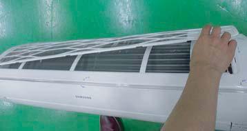
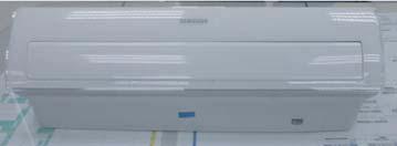
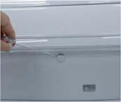
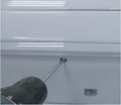
19 3-1 Indoor Unit Take care of the electrical shock by contact on the charging parts before the discharge after power of.(if takes approximately 2 minutes to discharge.). AJ007JNADCH/AJ009JNADCH/AJ012JNADCH/AJ018JNADCH/AJ024JNADCH No Parts Procedure Remark 1 PANEL-FRONT 1) Stop the driving of air conditioner and shut off main power supply. 2) Detach FILTER PRE from the PANEL FRONT. 3) Cover Panel is assembled on bottom of indoor unit as shown in the figure. Remove the Cap Screw as shown on the right side and then remove the screw and separate the Cover Panel. 3-2 Samsung Electronics

 Separate the hook after pushing both")

 Raise front part upward obliquely as")
20 No Parts Procedure Remark 4) Cover Panel is fixed to body by Hook in center area and side area. 5) Separate the hook after pushing both end of Cover Panel as shown in the figure. (Watch out for the damage of the hook) 6) Raise front part upward obliquely as shown in the figure and then remove the hooks Samsung Electronics 3-3


21 No Parts Procedure Remark Caution Assembly of Cover Panel after service end. - Reassembly is in the reverse order of the removal. - Piping and drain hose must be careful not to damage and Progress must be done with both hands. 3-4 Samsung Electronics

 8) To detach the")


22 No Parts Procedure Remark 7) To detach the PANEL-FRONT from the main frame, unfasten 2 screws at the bottom. (use + Screw Driver) 8) To detach the COVER-PANEL from the main frame, loosen 4 HOOK Structures. When separate the hook : Use the (-) screw Driver. (-)Screw Driver Insert the hook and then pull the hook as shown on the right side. (Watch out for the damage of the hook) Samsung Electronics 3-5
 Remove the")


23 No Parts Procedure Remark 9) Remove the Panel Frame from the Main Frame as shown on the right side. 3-6 Samsung Electronics
 Loosen MOTOR Wire.")
 Loosen the terminal block wires.")
 Loosen the Thermistor wire connector, Display wire")
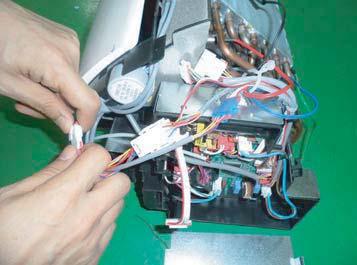
24 No Parts Procedure Remark 2 CONTROL IN 1) Loosen Stepping MOTOR Wire / BLADE Wire 2) Loosen MOTOR Wire. Caution: When you separate the connector,pull pressing the locking button. 3) Loosen the terminal block wires. Caution: When you separate the connector,pull pressing the locking button. 4) Loosen the Thermistor wire connector, Display wire connector. Caution: When you separate the connector,pull pressing the locking button. Samsung Electronics 3-7


25 No Parts Procedure Remark 2 CONTROL IN 5) Take off the CASE-CONTROL from the main frame after loosen the remaining connector. Caution: When you separate the connector,pull pressing the locking button 3 TRAY DRAIN 1) To detach TRAY-DRAIN from the main frame, pull the bottom of the TRAY- DRAIN towards you. 3-8 Samsung Electronics
 Detach the HOLDER PIPE.")
 3)")
 4) To detach")

26 No Parts Procedure Remark 4 Evaporator 1) Detach the HOLDER PIPE. 2) Unfasten the screw at the left side. (use + Screw Driver) 3) Unfasten the screw at the right side. (use + Screw Driver) 4) To detach Evaporator from the main frame, pull the bottom of the Evaporator towards you. Samsung Electronics 3-9
")
 2)")
 Unfasten the screw a")
 4) Pull")
27 No Parts Procedure Remark 5 FAN MOTOR CROSS FAN 1) Unfasten the screw. (use + Screw Driver) 2) Detach the FAN Motor case. 3) Unfasten the screw a little. (use + Screw Driver) 4) Pull the CROSS-FAN to the left side Samsung Electronics
")
 Disassemble 2")


28 AJ009JNLDCH/AJ012JNLDCH No Parts Procedure Remark 1 Motor Blower 1) Disassemble the Cabinet Top Motor. - Unscrew 8 screws 2) Disassemble 2 Cover Blower Uppers. - After unscrewing 2 screws - Disassemble the Cover Blower Upper with pushing its hook. 3) Disassemble the Cover Control. - Unscrew 2 screws Samsung Electronics 3-11

 Disassemble the band Motor for fixing the")
 After disassembling the Motor and Blower")
29 No Parts Procedure Remark 4) Disassemble Motor Wires connected to the inside of PCB and connected to the Capacitor. 5) Disassemble the Motor earth wire connected to the Partition. - Unscrew a screw 6) Disassemble the band Motor for fixing the Motor. - Unscrew 2 screws 7) After disassembling the Motor and Blower for the set, disassemble the Blower by use of 3mm wrench Samsung Electronics


 Disassemble the Drain")
30 No Parts Procedure Remark 2 Drain Pan 1) Disassemble the Cabinet Top Evap. - Unscrew 11 screws 2) Disassemble the Bracket Outlet Sub that fixes the Drain Pan equipped on the front of the set. - Unscrew 6 screws 3) Disassemble the Drain Cushion from the set. Samsung Electronics 3-13
 and the Drain Pan 2-1), 2-2), 2-3).")
 Disassemble the refrigerant temperature sensor, Inlet air")

31 No Parts Procedure Remark 3 Evaporator The Evaporator should be disassembled after disassembling the Cover Control 1-3) and the Drain Pan 2-1), 2-2), 2-3). 1) Disassemble the Cover Pipe that fixes the high/low pressure Pipe. - Unscrew 3 screws 2) Disassemble the refrigerant temperature sensor, Inlet air temperature sensor. 3) Disassemble the Support Evap. LF that fixes the Evaporator. - Unscrew 2 screws 4) Disassemble the Support Evap RH. - Unscrew 2 screws 3-14 Samsung Electronics
.")
 In case of disassembling the PCB separately, disassemble the PCB from the case with pushing the hook")
 Disassemble the Case PCB from Case control in - Unscrew 2 screws 4) In case of")
32 No Parts Procedure Remark 5) Disassemble the Evaporator form the set. 4 Control In * The Control In should be disassembled after disassembling the Cover Control 1-3). 1) Disassemble all Control Wires connected to the inside of PCB. 2) In case of disassembling the PCB separately, disassemble the PCB from the case with pushing the hook after unscrewing the screw. - Unscrew 1 screw 3) Disassemble the Case PCB from Case control in - Unscrew 2 screws 4) In case of disassembling the Case Control,disassemble the Case Control from the set after unscrewing the screw connected to cover bottom fan. - Unscrew 2 screws Samsung Electronics 3-15
 Pull out")

33 AJ018JNLDCH No Parts Procedure Remark 1 Filter 1) Pull out the Filter as picture 1 or picture Samsung Electronics

 After disassembling 3 indicating screws,")

34 No Parts Procedure Remark 2 Blower Motor 1) After disassembling 13 indicating screws, detach Ass y Cabinet-Top Motor. 2) After disassembling 3 indicating screws, detach Ass y Case Blower Upper. Press the pothook of the Case Blower and detach Ass y Case Blower Upper. Samsung Electronics 3-17

 Detach the Motor Wire")
 After disassembling the")


35 No Parts Procedure Remark 3) After disassembling 2 indicating screws, detach the Cover Control. 4) Detach the Motor Wire Connected to PCB and Capacitor. 5) After disassembling the indicating screws, detach the wire connected to the Partition. 6) After disassembling 2 indicating screws, detach the Ass y Band Motor Samsung Electronics


36 No Parts Procedure Remark 7) After disassembling the Motor and Blowers, detach the Blowers from the axis of the Motor by 3mm inner hexagon spanner. 3 Drain Pan 1) After disassembling 12 indicating screws, detach Ass y Cabinet-Top Evap. 2) After disassembling 6 indicating screws, detach the Bracket Outlet. 3) Detach the Drain Pan. Samsung Electronics 3-19
 and")
 Disassemble the Cover Pipe that fixes the high/low pressure")


37 No Parts Procedure Remark 4 Evaporator The Evaporator should be disassembled after disassembling the Cover Control 1-3) and the Drain Pan 2-1), 2-2), 2-3). 1) Disassemble the Cover Pipe that fixes the high/low pressure Pipe. - Unscrew 3 screws 2) Disassemble the refrigerant temperature sensor, Inlet air temperature sensor. 3) After disassembling 2 indicating screws, detach Ass'y Support Evap LF. 4) After disassembling 2 indicating screws, detach Ass'y Support Evap RH Samsung Electronics
.")
 In case of disassembling the PCB separately, disassemble the PCB from the case with pushing the hook.")
38 No Parts Procedure Remark 5) Disassemble the Evaporator form the set. 5 Control In The Control In should be disassembled after disassembling the Cover Control 1-3). 1) Disassemble all Control Wires connected to the inside of PCB. 2) In case of disassembling the PCB separately, disassemble the PCB from the case with pushing the hook. 3) Disassemble the Case PCB from Case control in - Unscrew 2 screws 4) If only the disassembly of Case Control is required, detach it from the set after disassembling 2 indicating screws. Samsung Electronics 3-21
 Pull both hooks and")

 Detach the safity clip and take up the grille.")


39 AJ009/012/018JNNDCH, AJ009/012/018NBNDCH No Parts Procedure Remark 1 Panel 1) Pull both hooks and take the grille downward. Two safety clips are mounted to the front grille to prevent it from dropping. 2) Detach the safity clip and take up the grille. 3) Remove the 2 fixed screws to remove the Control-Box Cover. (Use +Screw Driver) 4) Remove the Remocon-Receiver and Blade Connector Wire from the PBA. (3EA) 5) Push the 4 panel corners and cover downwards to remove it Samsung Electronics

 Press the Hangers at both sides of the panel")

")

40 No Parts Procedure Remark 6) Disassemble the bolts that are assembled with the indoor unit at the 4 panel corners. 7) Press the Hangers at both sides of the panel inwards, to remove it from the indoor unit s hook. Remove the panel from the indoor unit. 2 Control-Box 1) Disconnect the Connector Wire that is connected to the indoor unit s PBA 2) Unscrew the 2 fixed screws on both sides of the Control Box, and disassemble the Control Box from the indoor unit.(use +Screw Driver) Samsung Electronics 3-23


 Unscrew the screws on the 4")
 2) Remove the Drain Pan")
41 No Parts Procedure Remark 3 Bell-Mouth 1) Unscrew the screw fixed on the Bell-Mouth. (Use +Screw Driver) 2) Push the Bell-Mouth in the direction opposite to where it s installed on the Control-Box to remove it. 4 Drain Pan 1) Unscrew the screws on the 4 corners of the indoor unit. (Use +Screw Driver) 2) Remove the Drain Pan from the indoor unit Samsung Electronics

 2) Remove the 2 screws and take the")

 Use your hand to remove the")
42 No Parts Procedure Remark 5 Drain Pump Hose 1) Remove the 2 fixed screws and disconnect the white drainage hose from the Drain Pump. (Use +Screw Driver) 2) Remove the 2 screws and take the Drain-Hose out from the indoor unit to disassemble the transparent Drain-Hose fixed on the side of the indoor unit. (Use +Screw Driver) 6 Evap. Temperature Sensor 1) Use your hand to remove the temperature sensor attached to the Evap Pipe along with the fixing clip. Samsung Electronics 3-25

 Turn the three hexangular nuts on the Motor counterclockwise to remove the")


43 No Parts Procedure Remark 7 Fan Motor 1) Turn the hexangular nut attached to the top of the Fan counterclockwise to remove it. Take the Fan out of the Motor. 2) Turn the three hexangular nuts on the Motor counterclockwise to remove the nuts. Take the Motor Wires attached to these three locations out with your hands prior to removing the Motor. 8 Evaporator 1) Remove the screws of the Steel Holder Evaps that are used to fix the Heat Exchanger, and then remove it. (Use +Screw Driver) 2) Remove the 2 fixing screws of the Partition Evap at the Heat Exchanger s In/Out Pipe. (Use +Screw Driver) 3-26 Samsung Electronics


44 No Parts Procedure Remark 3) Remove the screw of the Cover Pipe that is used to fix the In/Out Pipe. Remove the In/Out Pipe. (Use +Screw Driver) 4) Remove the Heat Exchanger from the indoor unit s cabinet. Samsung Electronics 3-27
 Loosen 7 fixing screws and detach the Cabinet side RH.")
45 3-2 Outdoor Unit Take care of the electrical shock by contact on the charging parts before the discharge after power of.(if takes approximately 2 minutes to discharge.). AJ020JCJ2CH/AJ024JCJ3CH No Parts Procedure Remark 1 Common Work Control Out You must turn off the Power before disassembly. 1) Loosen 7 fixing screws and detach the Cabinet side RH. (Use +Screw Driver.) 2) Detach the Cable-Connector Wire from the Terminal-Block. 3) Loosen 2 fixing screws of the Ass'y Control Out. (Use +Screw Driver.) 4) Loosen 6 fixing screws and detach the Cabinet Upper. (Use +Screw Driver.) 5) Loosen 2 fixing screws, 7 bolts and detach the Cabinet Front. (Use +Screw Driver.) 3-28 Samsung Electronics

 7) Pull the felt and detach it.")

46 No Parts Procedure Remark 6) Loosen 2 fixing screw and pull up the Control Box. (Use +Screw Driver.) 7) Pull the felt and detach it. 8) Detach the Terminal Cover and detach the comp lead wire. Samsung Electronics 3-29
 2) Loosen 4 fixing bolts and detach the Motor. (Use +Screw Driver.")
 3 Heat Exchanger Compressor 1) Release the refrigerant at first.")
 Loosen the fixing screw of the Heat Exchanger. (Use +Screw Driver.")
47 No Parts Procedure Remark 2 Fan Moter 1) Loosen the fixing nut and detach the Fan. (Use Monkey Spanner.) 2) Loosen 4 fixing bolts and detach the Motor. (Use +Screw Driver.) 3) Loosen 4 fixing bolts and detach the Bracket Motor. (Use +Screw Driver.) 3 Heat Exchanger Compressor 1) Release the refrigerant at first. 2) Disassemble the Inlet and Outlet Pipe by welding. 3) Loosen the fixing screw of the Heat Exchanger. (Use +Screw Driver.) 4) Detach the Heat Exchanger. 5) Loosen 3 nuts of the Compressor. (Use Monkey Spanner.) 6) Detach the Compressor Samsung Electronics


 3 Cabi Top 1) Unscrew and remove 9 screws")
 Samsung Electronics 3-31")
48 AJ036JCJ5CH No Parts Procedure Remark 1 Cabi Side RH You must turn off the Power before disassembly. 1) Unscrew and remove 6 mounting screw in the Cabinet Side RH. (Use +Screw Driver) 2 Cabi Front RH 1) Unscrew and remove 6 mounting screw in the Cabinet Side RH. (Use +Screw Driver) 3 Cabi Top 1) Unscrew and remove 9 screws on each side of the Cabinet-Top. (Use +Screw Driver) Samsung Electronics 3-31
 Pull the sensor")
 Unscrew and remove 4 screws")
 5 Cabi")


 3) Pull")
49 No Parts Procedure Remark 4 Guard Cond 1) Pull the sensor from Guard Cond. 2) Unscrew and remove 4 screws in the Guard Cond. ( Use + Screw Driver ) 5 Cabi Back RH 1) Pull the sensor from Cabi Back RH. 2) Unscrew and remove 5 screws on each side of the Cabinet Back RH. ( Use + Screw Driver ) 3) Pull the hook of Cabi Back RH from the Bracket Valve Samsung Electronics


 7")

 Samsung")
50 No Parts Procedure Remark 6 Plate Case Control Support 1) Unscrew and remove 2 screws in the plate Case control Support. ( Use + Screw Driver ) 7 Cabi Back RH 1) Unscrew and remove 10 screws in the Cabinet-Front LF ( Use + Screw Driver ) Samsung Electronics 3-33


 3) Disconnect the Motor wire")
 Unscrew and remove 2 mounting")
51 No Parts Procedure Remark 8 Fan 1) Turn 2 mounting nuts as shown in the picture and remove it. (Use Adjustable Wrench) 9 Motor 1) Separate the Fan Propeller. 2) Unscrew and remove the 8 Motor mounting screws. (Use +Screw Driver) 3) Disconnect the Motor wire From Ass'y Control Out. 10 Bracket Motor 1) Unscrew and remove 2 mounting screws in Bracket Motor. (Use +Screw Driver) 3-34 Samsung Electronics
")


52 No Parts Procedure Remark 11 Control Out 1) Disconnect 9 Connecters From Ass'y Control Out. 2) 3) Unscrew and remote 2 mounting screw in Control Out.(Use + Screw Driver) Separate Ass'y Control Out Samsung Electronics 3-35
 Separate the pipe from the Entrance/ Exit using a welder.")

 Separate the pipe from the Entrance/ Exit using")
 14 Compressor 1) Unscrew and remove 1 mounting")
53 No Parts Procedure Remark 12 Ass'y 4way Valve 1) Purge the Coolant first. 2) Separate the pipe from the Entrance/ Exit using a welder. When removing the compressor,heat Exchanger, and Pipe, purge the Coolant inside the Compressor completely and remove the pipe with a welding flame. 13 Assy EEV Valve 1) Separate the pipe from the Entrance/ Exit using a welder. 2) Unscrew and remove 2 mounting screws in Service Valve. (Use +Screw Driver) 14 Compressor 1) Unscrew and remove 1 mounting nut in Cover Terminal. (Use Adjustable Wrench) 3-36 Samsung Electronics

 As shown in the picture,")

 Unscrew and")

54 No Parts Procedure Remark 2) Separate the Compressor Felt Sound. 3) As shown in the picture, unscrew and remove 3 mounting screws from the bottom. (Use Adjustable Wrench) 15 Cond Out 1) Unscrew and remove 3 screws on each side of the Assy Cond Out. (Use +Screw Driver) Samsung Electronics 3-37
55 MEMO 3-38 Samsung Electronics
56 4. Troubleshooting 4-1 Display Error and Check Method Indoor unit AJ009JNNDCH/AJ012JNNDCH/AJ018JNNDCH Abnormal conditions LED lamp display Operation Defrost Timer Filter Remarks Power reset X X X Error of temperature sensor in the indoor unit (Open/Short) X X X Error of heat exchanger sensor in the indoor unit (Open/Short) X X Error of fan motor in the indoor unit X X X Error of the outdoor temperature sensor Error of the condensor temperature sensor X X Error of the discharge temperature sensor No communication for 2 minutes between indoor and outdoor unit X X (communication error for more than 2minutes) Error of outdoor unit X Detection of the float switch X X EEPROM error X EEPROM option error Motion detect sensor error X X Mixed operation error X X X On Flickering X Off If you turn off the air conditioner when the LED is flickering, the LED is also turned off. Samsung Electronics 4-1
57 AJ009JNLDCH/AJ012JNLDCH/AJ018JNLDCH LED Display on the receiver & display unit Indicators Concealed Type Abnormal conditions Green Red Remarks Standard Type Power reset X X X X Error of temperature sensor in the indoor unit (Open/Short) Error of heat exchanger sensor in the indoor unit Error of heat exchanger OUT sensor in indoor unit Error of outlet temperature sensor in indoor unit (Open/Short): For heat pump models only X X X X X X X Displayed on appropriate indoor unit which is operating Displayed on appropriate indoor unit which is operating Error of mixed operation X X X Error of outdoor temperature sensor Error of COND sensor Error of DISCHARGE sensor 1. No communication for 2 minutes between indoor units (Communication error for more than 2 minutes) 2. Indoor unit receiving the communication error from outdoor unit 3. Outdoor unit tracking 3 minutes error 4. When sending the communication error from the outdoor unit, the mismatching of the communication numbers and installed numbers after completion of tracking. (Communication error for more than 2 minutes) X X X X X X Displayed on appropriate indoor unit which is operating Displayed on outdoor unit 1. Error of indoor unit: Displayed on the indoor unit regardless of operation 2. Error of outdoor unit: Displayed on the indoor unit which is operating On Flickering X Off If you turn off the air conditioner when the LED is flickering, the LED is also turned off. If you re-operate the air conditioner, it operates normally at first, then detect an error again. 4-2 Samsung Electronics
58 AJ009JNLDCH/AJ012JNLDCH/AJ018JNLDCH LED Display on the receiver & display unit Indicators Concealed Type Abnormal conditions Green Red Remarks Standard Type Self-diagnostic error (including the indoor unit not detected) 1. Error of electronic expansion valve close 2. Error of electronic expansion valve open 3. Breakaway of EVA OUT sensor 4. Breakaway of EVA IN sensor X X Displayed on appropriate indoor unit which is operating Displayed on outdoor unit 5. Breakaway of COND MID sensor 6. 2nd detection of refrigerant completely leak 7. 2nd detection of high temperature COND 8. 2nd detection of high temperature DISCHARGE 9. COMP DOWN due to 2nd detection of low pressure switch 10. Error of reverse phase 11. Compressor down due to 6th detection of freezing 12. Self-diagnosis of condensation sensor (G8, G9) 13. Compressor down due to condensation ratio control X X Displayed on appropriate indoor unit which is operating Displayed on outdoor unit Error of float switch X X X Error of setting option switches for optional accessories X X X EEPROM error X X EEPROM option error X On Flickering X Off If you turn off the air conditioner when the LED is flickering, the LED is also turned off. If you re-operate the air conditioner, it operates normally at first, then detect an error again. Samsung Electronics 4-3
59 AJ007JNADCH/AJ009JNADCH/AJ012JNADCH/AJ018JNADCH/AJ024JNADCH LED Display on the receiver & display unit Error indicator Display LED Display LED 1 LED 2 LED 3 Error Measures to take by an installer / /, display and all LED blinks, Commnuication Error between Indoor and outdoor unit Error on indoor temperature sensor Error on indoor heat exchanger Error on indoor fan motor EEPROM/Option error Error 1. Check the connection wire between indoor and outdoor unit. (whether the power cable and commnunication cable is crossed or not) 1. Check the connection of the connector 1. Check the connection of the connector 1. Check the connection of the connector 2. Remove foreign substance (Check for the cause that restrains motor) 1. Re-set options 1. Check if the service valve is completely open. 2. Check if there s any blockage in the refrigerant pipe which connects indoor and outdoor unit. 3. Check for refrigerant leak. Above LED pattern is displayed when there s error is occurred on outdoor unit. Check the LED display on outdoor unit for the details. Lack of Refrigerant (For Inverter model only) 1. refrigerant was charged for the pipe length that exceeds 7.5m. 2. Check for refrigerant leak between valve and pipe connection. On Flickering X Off If you turn off the air conditioner when the LED is flickering, the LED is also turned off. If you re-operate the air conditioner, it operates normally at first, then detect an error again. 4-4 Samsung Electronics
60
61 4-1-2 Outdoor unit AJ020JCJ2CH/AJ024JCJ3CH/AJ036JCJ5CH The table below give indication about self diagnostic routine. Some of error code requires activities exclusively for Authorise Service Center. The error indicated on the PCB display of outdoor unit DISPLAY EXPLANATION (The error indicated on the PCB display of outdoor unit) REMARK Communiaction error(indoor unable to receive data) Outdoor unit communication error(abnormal data from indoor unit over 60 packet) Indoor unit room temperature sensor error (Open/Short) Check electrical connection and setting Check electrical connection and setting Indoor unit heat exchanger in temperature sensor error (Open/Short) Indoor unit heat exchanger out temperature sensor error (Open/Short) Indoor unit sensor error-evaporator pipe in sensor - Self diagnosis Indoor unit sensor error-evaporator pipe out sensor - Self diagnosis Indoor Unit FAN Error More than two indoor units cool and heat simultaneously Indoor Unit EEPROM Error Indoor Unit EEPROM Option Error EVA-MID BREAK AWAY EVA-IN BREAK AWAY EVA-OUT BREAK AWAY Failure of pipe check operation No pipe check operation check - occasion : try to operation after the installation through auto addressing mode without pipe check operation. Check setting The number of Indoor unit mismatched Communication error between the outdoor and indoor unit Outdoor communication error between main micom and inverter micom Outdoor communication error beween main micom and hub micom Outside temperature sensor error(short/open) - Error level: over 4.9V(-50 C) under 0.4V(93 C) Condenser temperature sensor error(short/open) - Error level: over 4.9V(-50 C) under 0.4V(93 C) Outdoor unit sensor error - Condenser out sensor(short/open) - Self diagnosis Compressor Discharge temperature sensor error Compressor discharge sensor detached - Self diagnosis Compressor OLP sensor error (Short/Open) - Error condition : outdoor temperature under -20 C - Error level : over 4.95V(-30 C) under 0.5V(151 C) EvaIn1 Sensor Short/Open EvaIn2 Sensor Short/Open EvaIn3 Sensor Short/Open EvaIn4 Sensor Short/Open EvaIn5 Sensor Short/Open EvaOut1 Sensor Short/Open Check piping connection and setting Check electrical connection and setting Check electrical connection and setting Samsung Electronics 4-5
62 AJ020JCJ2CH/AJ024JCJ3CH/AJ036JCJ5CH DISPLAY EXPLANATION (The error indicated on the PCB display of outdoor unit) REMARK EvaOut2 Sensor Short/Open EvaOut3 Sensor Short/Open EvaOut4 Sensor Short/Open EvaOut5 Sensor Short/Open Outdoor unit freezing(compressor stop) Outdoor unit overload - Safety control(compressor stop) Outdoor unit high discharge temperature - Safety control (Compressor stop) check pipe lenght, indoor unit filter, refrigerant leakage/charge and service port check pipe lenght, refrigerant leakage/charge check pipe lenght, refrigerant leakage/charge Outdoor unit EEV open (Stopped indoor unit s) -Self diagnosis Outdoor unit EEV open (operating indoor unit s) -Self diagnosis High temperature(over 30 C) of outdoor as heating mode Low temperature(under -10 C) of outdoor as cooling mode Outdoor Fan Error Communication cable mismatched between indoor and outdoor unit Check electrical connection Inverter compressor starting failure (5 times) Compressor trip by input current control mode (PFC over current) Compressor trip by OLP temperature control mode Over current Compressor Vlimit Error DC link Voltage error (under 150V, over 410V) Abnormal compressor running (Compressor Rotation Error) Current sensor error DC link Voltage sensor error Outdoor unit EEPROM Error Inverter micom zero-crossing error Over voltage Error 4-6 Samsung Electronics
63 4-2 Setting Option Setup Method Setting an indoor unit address and installation option Setting Option (AJ***JNN/JNA***) Entering mode for setting option Option setting mode Mode change High Temp Button Low Temp Button High Fan Button Low Fan Button Setting Option 1. Remove batteries from the remote controller 2. Insert batteries and enter the option setting mode while pressing High Temp button and Low Temp button. 3. Each time you press Low Fan button, 7-seg on left side is increased by 1 and each time you press High Fan button, 7-seg on right side is increased by 1 4. You press button to move to the next setteing page. 5. After setting option, press button to check whether the option code you input is correct or not. 6. Press operation button with the direction of remote control for set. EX) Set the each option separately since you cannot set the ADDRESS setting and indoor unit installation setting option at the same time. Samsung Electronics 4-7
64 The procedure of setting option Operation * Step 1 1. Remove the batteries from the remote controller. 2. Insert batteries while pressing High Temp Button and Low Temp Button. Indication * Step 2 1. Press Low Fan button to enter SEG2 value. 2. Press High Fan button to enter SEG3 value. * Step 3 Press Mode button to be change to Cool mode in the ON status. 1. Press Low Fan button to enter SEG4 value. 2. Press High Fan button to enter SEG5 value. * Step 4 Press Mode button to be changed to DRY mode in the ON status. 1. Press Low Fan button to enter SEG6. 2. Press High Fan button to enter SEG8. * Step 5 Press Mode button to be changed to FAN mode in the ON status. 1. Press Low Fan button to enter SEG9 value. 2. Press High Fan button to enter SEG10 value. * Step 6 Press Mode button to be changed to HEAT mode in the ON status. 1. Press Low Fan button to enter SEG11 value. 2. Press High Fan button to enter SEG12value * Step 7 Press Mode button to be changed to AUTO mode in the OFF status. 1. Press Fan button to enter SEG14 value. 2. Press High Fan button to enter SEG15 value. * Step 8 Press Mode button to be changed to Cool mode in the OFF status. 1. Press Low Fan button to enter SEG16 value. 2. Press High Fan button to enter SEG17 value. * Step 9 Press Mode button to be changed to DRY mode in the OFF status. 1. Press Low Fan button to enter SEG18 value. 2. Press High Fan button to enter SEG20 value. * Step 10 Press Mode button to be changed to FAN mode in OFF status 1. Press Low Fan button to enter SEG21 value. 2. Press High Fan button to enter SEG22 value. * Step 11 Press Mode button to be changed to HEAT mode in the OFF status 1. Press Low Fan button to enter SEG23 value. 2. Press High Fan button to enter SEG24 value. * Step 12 Press Mode button to check whether the option code you entered is correct or not. Press operation button to enter option. 4-8 Samsung Electronics
65 Setting an indoor unit address (MAIN/RMC) 1. Check whether power is supplied or not. - When the indoor unit is not plugged in, there should be additional power supply in the indoor unit. 2. The panel(display ) should be connected to an indoor unit to receive option. 3. Before installing the indoor unit, assign an address to the indoor unit according to the air conditioning system plan. 4. Assign an indoor unit address by wireless remote controller. - The initial setting status of indoor unit ADDRESS(MAIN/RMC) is "0A " - There is no need to assign extra ADDRESS for 1:1 installation between indoor unit and outdoor unit. Option No. : 0AXXXX-1XXXXX-2XXXXX-3XXXXX Option SEG1 SEG2 SEG3 SEG4 SEG5 SEG6 Explanation PAGE MODE Remote Controller Display Indication and Details Setting Main address 100-digit of indoor unit address 10-digit of indoor unit A single digit of indoor unit Indication Details Indication Details Indication Details Indication Details Indication Details Indication Details 0 A 0 No Main address 0~9 100-digit 0~9 10-digit 0~9 Main 1 address setting mode Option SEG7 SEG8 SEG9 SEG10 SEG11 SEG12 Explanation Remote Controller Display PAGE Setting RMC address Group channel(*16) A single digit Group address Indication Details Indication Details Indication Details Indication Details Indication Details Indication Details 1(L) 2(N) Indoor Unit F2 F1 Indication and Details No RMC address RMC address setting mode You must set RMC address setting mode when using the centralized Control. RMC1 1~F RMC2 1~F Samsung Electronics 4-9
66 5. The MAIN address is for commnication between the indoor unit and the outdoor unit. Therefore, you must set it to operate the air conditioner properly. Setting an indoor unit installation option (suitable for the condition of each installation location) 1. Check whether power is supplied or not. - When the indoor unit is not plugged in, there should be additional power supply in the indoor unit. 2. The panel(display ) should be connected to an indoor unit to receive option. 3. Before installing the indoor unit, assign an option to the indoor unit according to the air conditioning system plan. - The default setting of an indoor unit installation option is Individual control of a remote controller(seg20) is The function that controls an indoor unit individually when there is more than one indoor unit. 4. Set the indoor unit option by wireless remote controller. - When entering Address option, connect remote controller receiver. 1(L) 2(N) Indoor Unit F2 F1 Option SEG1 SEG2 SEG3 SEG4 SEG5 SEG6 Explanation PAGE MODE Central control Indication Details Indication Details Indication Details Indication Details Indication Details Indication Details Indication and Details 0 No use Use 0 Option SEG7 SEG8 SEG9 SEG10 SEG11 SEG12 Explanation PAGE Master / Slave Indication Details Indication Details Indication Details Indication Details Indication Details Indication Details Indication and Details 0 Slave Master Option SEG13 SEG14 SEG15 SEG16 SEG17 SEG18 Explanation PAGE External control External control output Buzzer Indication Details Indication Details Indication Details Indication Details Indication Details Indication Details 0 No use Indication and Details 0 Thermo ON 0 Use 1 On/Off control Off control 1 Operation ON 1 No Use 3 Window On/Off control 1) Option SEG19 SEG20 SEG21 SEG22 SEG23 SEG24 Explanation PAGE Indication Details Indication Details Indication Details Indication Details Indication Details Indication Details Indication and Details If you input a number other than 0~4 of the individual control of the indoor unit(seg20), the indoor is set as "indoor 1". 1) The window on/off function applies to the following unit - AJN**/AR** 4-10 Samsung Electronics
67 4-2-2 Changing a particular option MODEL OPTION CODE AJ007JNADCH A A04 AJ009JNADCH A A04 AJ012JNADCH B B04 AJ018JNADCH A-27323C AJ024JNADCH C AJ009JNLDCH E AJ012JNLDCH AJ018JNLDCH E AJ009JNNDCH 01507F-1660F8-231A AJ012JNNDCH 01507F AJ018JNNDCH 01507F-17625D-23343C If you are going to use up to SEG 24, please refer to following instruction. SEG 18 : Not in use Use Change temperature display 0(Celsius) 1(Fahrenheit) Sound Mute 0 2 If you want to use multiple functions, add each of the use value of the function you want to used and input the addition as option value. (Use Fahrenheit + Sound mute : = 3) Ex) d00e When using Sound mute : d00e When using Fahrenheit and Sound mute : d00e al Option AJ009NBNDCH/AA AJ012NBNDCH/AA AJ018NBNDCH/AA SEG1~6 0150CF 0150CF 0150CF SEG7~ F D SEG13~18 201A C SEG19~ SEG25~ SEG31~ SEG37~ SEG43~ SEG49~ SEG55~ SEG61~ SEG67~ Samsung Electronics 4-11
68 4-3 Items to be checked first 1. The input voltage should be rating voltage ±10% range. The air conditioner may not operate properly if the voltage is out of this range. 2. Is the link cable linking the indoor unit and the outdoor unit linked properly? The indoor unit and the outdoor unit shall be linked by 4 cables. Check the terminals if the indoor unit and outdoor unit are properly linked by the same number of cables. Otherwise the air conditioner may not operate properly. 3. When a problem occurs due to the contents illustrated in the table below it is a symptom not related to the malfunction of the air conditioner. No 1 Operation of air conditioner In a COOL operation mode, the compressor does not operate at a room temperature higher than the setting temperature that the INDOOR FAN should operate. In a HEAT operation mode, the compressor does not operate at a room temperature lower than the setting temperature that indoor fan should operate. Explanation In happens after a delay of 3 minutes when the compressor is reoperated. The same phenomenon occurs when a power is on. As a phenomenon that the compressor is reoperated after a delay of 3 minutes, the indoor fan is adjusted automatically with reference to a temperature of the air blew 2 Fan speed setting is not allowed in AUTO( DRY( ) mode. ) or The speed of the indoor fan is set to LL in DRY mode. Fan speed is 5 steps and is selected automatically in AUTO mode. 3 Compressor stops operation intermittently in DRY( ) mode. Compressor operation is controlled automatically in DRY mode depending on the room temperature and humidity. 4 Compressor of the outdoor unit is operating although it is turned off in a HEAT mode. When the unit is turned off while de-ice is activated, the compressor continues operation for up to 12 minutes (maximum) until the deice is completed. 5 Timer LED( ) only of the indoor unit lights up and the air conditioner does not operate. Timer is being activated and the unit is in ready mode. The unit operates normally if the timer operation is cancelled. 6 The compressor and indoor fan stop intermittently in HEAT mode. The compressor and indoor fan stop intermittently if room temperature exceeds a setting temperature in order to protect the compressor from overheated air in a HEAT mode. 7 Indoor fan and outdoor fan stop operation intermittently in a HEAT mode. The compressor operates in a reverse cycle to remove exterior ice in a HEAT mode, and indoor fan and outdoor fan do not operate intermittently for within 20% of the total heater operation. 8 The compressor stops intermittently in a COOL mode or DRY mode, and fan speed of the indoor unit decreases. The compressor stops intermittently or the fan speed of the indoor unit decreases to prevent inside/outside air frozen depending on the inside/outside air temperature Samsung Electronics
69 4-3-1 Wiring checking function WARNING This product is prohibited one indoor unit installation. Don't use pipe checking operation and Auto Addressing Mode when one indoor unit is installed. Switch the system on and wait for code " " to appear on the display of the external unit (this requires approximately 60 seconds **). As soon as code " "displays, press once the red button (K1) shown on the figure on the side of the page: AJ020JCJ2CH/AJ024JCJ3CH WARNING If the quantity of indoor units connected is lower than maximum connectable to outdoor unit, the rotary switch SW01 has to be positioned, in order to select a number equal to indoor units quantity you connected. After the operations described above have been performed, the system starts in Cooling or Heating mode, depending on the external ambient temperature. After a few minutes (from a minimum of 3 to 5 minutes for the internal unit), the system stops automatically, completing the self-test and addressing procedure. " " appears on the display of the external unit. 20 seconds after the display of " " (that confirms the correct execution of the procedure), the following codes (if four internal units are connected) display in sequence on the display of the external unit: Display of the external unit AJ036JCJ5CH Display 1 Display 2 Description The outdoor unit is communication correctly together the indoor unit connected to refrigerant pipe A. The outdoor unit is communication correctly together the indoor unit connected to refrigerant pipe B. The outdoor unit is communication correctly together the indoor unit connected to refrigerant pipe C. The outdoor unit is communication correctly together the indoor unit connected to refrigerant pipe D. At this point it is possible to start the internal units in the desired mode If " "doesn t display, the procedure has failed and it is therefore necessary to read ALL the operator s manual before repeating the operating described in steps Display 1 Display 2 DIP Switch K1 Rotary Switch During the initial 60 seconds, display 1 shows in sequence: Samsung Electronics 4-13
70 4-3-2 Without wiring checking function Step 1 Review all the following elements in the installation: Installation site strength Piping connection tightness to detect any gas leakage Connection wiring Heat-resistant insulation of the piping Drainage Earthing wire connection Step 2 IMPORTANT! Before selecting switch turn off the system power supply Advise control we are going to proceeed with manual addressing as follow: AJ020JCJ2CH/AJ024JCJ3CH Switch Indoor unit address SW 02 Manual addressing - Move dipswitch n 1 of SW02 - outdoor unit display PCB down; Move down the switch n 1 Display of the external unit AJ036JCJ5CH Display 1 Display 2 DIP Switch K1 Rotary Switch Step 3 Step 4 Follow of indication reported into table below for indoor unit addressing Turn on the system power supply and waiting for 60 seconds after estabilishing communication between outdoor and indoor units. During this phase, the left display of outdoor unit display PCB DIS01 will count fom to 15. Estabilished communication the left display will count sequentially: 00--communication with indoor unit A; 01--communication with indoor unit B; 02--communication with indoor unit C; 03--communication with indoor unit D; In case of Manual address mode,you can do pipe check operation for check whether you connect the pipes correctly or not. But you need set indoor address switch yourselves Samsung Electronics
71 2 TYPE PICTURE MODEL TO SET ADDRESSING MANUALLY BY ROTARY SWITCH SW02 Same for: SLIM DUCT AJ009JNLDCH AJ012JNLDCH AJ018JNLDCH ROTARY SWITCH SW02 POSITION ACCORDING TO REFRIGERANT CIRCUIT CONNECTED ( 0=A; 1=B; 2=C; 3=D ) OUTDOOR UNIT Indoor Unit SW02 Att. "A" OUTDOOR UNIT 0 0 Indoor Unit SW02 Att. "A" A unit B unit Att. "B" 1 A unit B unit Att. "B" 1 C unit Att. "C" AJ020JCJ2CH AJ024JCJ3CH INSTALLATION TEST MODE (with all indoor units functioning) Please do cool mode try-run or heat mode try run. Cool mode try-run : Push the [K2] button three times. Heat mode try-run : Push the [K2] button once. After 12 minutes of stationary condition check each indoor unit air treatment: Cooling mode (indoor unit check) --> Inlet air temp. - Outlet air temp: From 10 K to 12 K ( indicative delta T) Heating mode (indoor unit check) --> Outlet air temp. - Inlet air temp: From 11 K to 14 K (indicative delta T) In heating mode, the indoor fan motor can remain off to avoid cold air blown into conditioned space. Samsung Electronics 4-15
72 4-4 Checking and Testing operations It could take maximum 60 minutes to operate for the protection of the compressor. if the outdoor temperature is below -5 C. Ampere Limit Setting & Changing Procedure WARNING Do not adjust the Ampere Limit Switch, if it s not necessary : before modifying it, evaluate the total number of electric and electronics loads consumption and use Ampere limits switch just as emergency solution or in case the system is anyway oversized compared to real thermal load needed. Ampere Limit Switch is initially set to the default value (table below). Ampere Limit Switch is on the PCB of outdoor unit. Contact the authorized service technician or dealer for setting and changing the Ampere Limit Switch. Before changing the Ampere Limit Switch, turn off the main power of the system. The designs and shape are subject to change according to the model. AJ020JCJ2CH/AJ024JCJ3CH Switch Selection AJ020JCJ2CH AJ024JCJ3CH AJ036JCJ5CH Switch A (Default) 16.6A (Default) 23.0A (Default) (OFF) ON ON 13.0A 14.0A 20.0A ON OFF Display of the external unit (OFF) AJ036JCJ5CH 10.0A 11.0A 18.0A OFF ON (OFF) 8.5A 10.0A 16.0A OFF OFF (OFF) Display 1 Display 2 DIP Switch K1 Rotary Switch 4-16 Samsung Electronics
73 To complete the installation, perform the following checks and tests to ensure that the air conditioner is operating correctly. 1. Review all the following elements in the installation: Settings of PCB Display of the Outdoor unit Key Options of PCB Display - K1 : pipe checking operation button - K2 : Function button - K3 : Reset button - K4 : View mode change button Push 1 Key K1 K2 K3 K4 Pipe Checking Operation (Display: ) K4 View mode Display changes Heat Mode Try run (Display: ) Refrigerant Charging (Display: ) Cool Mode Try run (Display: ) Pump down (Display: ) Reset View mode change Push Display Explanation Push Display Explanation 0 Present Compressor Frequency 8 Discharge temperature AJ020JCJ2CH/AJ024JCJ3CH K2 K3 K4 K1 Display of the external unit During the initial 60 seconds, display 1 shows in sequence: AJ036JCJ5CH 1 Target Compressor Frequency 9 OLP temperature 2 Order Compressor Frequency 10 Condenser temperature 3 EEV0 current step 11 Outdoor temperature 4 EEV1 current step 12 Running current 5 EEV2 current step 13 Target Discharge temperature 6 EEV3 current step3 14 Total capacity of the indoor units Display 1 Display 2 DIP Switch K1 Rotary Switch 7 Fan RPM (H: high, L: low, Blank: off) 15 Safety Control (just For Service Technician) The EEV 2 and EEV 3 of AJ020JCJ2CH model is always displayed as blank The EEV 3 of AJ024JCJ3CH model is always displayed as blank Samsung Electronics 4-17

74 2. Apply the power to the outdoor unit. Outdoor unit will try to communicate the number of indoor units specified by SW01 on outdoor display PCB. Does LED show "Normal display"? "Normal display" means, right 2 digit of LED on Display PCB displays '00' and left 2 digit of LED displays indoor unit address number. No Yes OK : This number is displayed only while communicating, so each number is displayed for a short time in order. Is error code started with '' displayed on the LED? '' No Nothing is displayed on the LED. Yes Check the indoor unit, outdoor unit or wiring according the error code table. Check the power source, power cable & FUSE on the outdoor unit. 2. Pipe Checking Operation (Auto Addressing Mode) Automated checking of pipe connection (Auto addressing option) -During these 60 seconds,the left dispaly DIS01 will show sequentially It means you didn t do Pipe check operation displaying as below. 2. Display Button [K1] 1 times DIS 01 DIS 02 Time duration [DIS 01 ] is flickering on the setting time. Outdoor Temperature or more less than (Cool mode) (Heat mode) 5min~10min 20min~50min 4-18 Samsung Electronics
75 Expected time of 4 indoor units installation. 00 -Estabilished communication with indoor unit A ; 01 -Estabilished communication with indoor unit B ; 02 -Estabilished communication with indoor unit C ; 03 -Estabilished communication with indoor unit D ; 00 -Estabilished communication with indoor unit A... Step 3 Mode Auto Addressing Manual Addressing Function Checking the connection only - If the auto addressing does not work according to the indoor unit capacity, model or installation condition,apply the manual addressing. When SW01 set "0"on Auto address mode,it means you install the maximum number of indoor unit. 1) Installation ID Unit Number=MAX Installation ID Unit Number of OD Unit. Don't need set SW01. 2) Installation ID Unit Number<MAX Installation ID Unit Number of OD Unit. Pls set SW01 as the number of which you install the indoor unit. On Manual address mode,you must set SW01 as the number of which you install the indoor unit. - This mode is for finding the combination between indoor unit and each valve on the outdoor unit. Because refrigerant flow is controlled with EEV in the outdoor, controller should know which EEV will control which indoor unit. - Once "PIPE CHECK MODE" is done normally, each indoor unit will remember the given address number by the outdoor unit and no need to do this checking. But in case of listed below, PIPE CHECK MODE should be done again. - On this mode the controller will ignore the manual address number set on the rotary switch on the indoor PCB. - To confirm the indoor address number assigned by this mode, use "TESTMODE" and the address number will be displayed on the LED display on the indoor unit. Samsung Electronics 4-19
76 If Error code is displayed on indoor or outdoor LED, check as follows; - Manaul address setting Q1 Step 1 Contents Turn on the system. But outdoor units PCB displayed E201 or E101 Error code. Check point Check to Number of indoor unit s SW01. Remarks Outdoor PCB SW01 Step 2 Check to power cable to indoor units. Check to communication cable indoor units. Wire connect Q2 Guidance Step 1 Contents Turn on the system. But outdoor units PCB displayed E203 Error code. Check point Outdoor communication error between the outdoor main PCB and sub PCB. Check to sub PCB wire and replace it. Remarks Outdoor PCB SW01 Wire connect Q3 Error code E121 E122 E123 E154 Guidance Contents Turn on the indoor units. But indoor unit displayed E121/122/123/154 Error code. Explanation Indoor unit room temperature sensor error (open/short) Indoor unit heat exchanger in temperature sensor error (open/short) Indoor unit heat exchanger out temperature sensor error (open/short) Indoor unite fan error Please, all units turn off and check to indoor unit s PCB and wire connection. E121/122/123 error detected, replace related sensor. Q4 Error code E162 E163 Guidance Contents Turn on the system. But indoor unit displayed E162/163 Error code. Explanation Indoor unit EEPROM Error. Indoor unit EEPROM Option Error. Please, all units turn off and follow guidance. E163 : Please reset indoor Option code. E163 : If you don t know about that, replace indoor unit PCB which is related. E162 : Please replace indoor unit PCB which is related. Q5 Error code E221 E237 E251 E251 E320 Guidance Contents Turn on the system. But outdoor unit displayed E221/237/251/320 Error code. Explanation Outside temperature sensor error (open/short) Indoor unit heat exchanger in temperature sensor error (open/short) Condenser temperature sensor error (open/short) Compressor Discharge temperature sensor error (open/short) Compressor OLP sensor error (open/short) Please, The System turn off and replace sensor which is related Samsung Electronics
77 Q6 Analysis Contents Indoor units address SW setting correct, but outdoor unit s PCB displayed E201 Error Code. Check point Remarks Indoor unit s sub PCB address SW or sub PCB is connected by mistake. Step 1 Step 2 Check to indoor unit s sub PCB wire connecting condition.(misconnecting or Sub PCB is out of order) Address setting mode change to auto address setting. Indoor Sub PCB Step 3 Guidance Following auto address setting steps. Manual Address setting is Option in FJM PLUS A. But we solved problem like this situation, with auto address setting. - Auto address setting Q1 Analysis Contents When the pipe checking operation is finished, outdoor sub PCB display E190 Error code. Check point Remarks Outdoor unit fails to search indoor units or to check The pipe checking operation indoor address. Step 1 Step 2 Step 3 Whether The gas and liquid pipes are crossed with each other, check to connecting. Check to outdoor unit s EEV coil being connected in proper location. Check to indoor unit s sensor being connected in proper location. Pipe connecting EEV Coil Indoor sensor Guidance During the pipe checking operation, system check temperature change of indoor Heat exchanger.in case, indoor sensor defect, EEV coil connector detach, malfunction of EEV, Leakage of Refrigerant, and etc can make this case. - Address setting another case Q1 Analysis Contents When the system installation is finished, outdoor unit s PCB display E202 Error code. Check point Remarks This problem is caused by outdoor unit s communication part trouble or indoor units power and communication line trouble. The pipe checking operation Step 1 Step 2 Check to connect outdoor unit and indoor units cable. Replace outdoor unit s ass y control or indoor unit s ass y control. Pipe connecting EEV Coil Guidance Basically, This error caused by communication between Indoor Units and Outdoor Unit. First of all, check the all communication connection and PCB s status. Samsung Electronics 4-21
78 - Operation Error Q1 Analysis Guidance Contents While using cooling or heating, indoor units display E161 Error code Check point Remarks This problem is caused by user s fault. User s simultaneously operate 2 more indoor units in the same time cooling and heating mode. FJM is operate by just cooling or heating mode only. (Only, HR system can operate cooling and heating mode simultaneously in the same time) Outdoor unit will be operate by first received signal, another operation signal is not applied system. Q2 Analysis Contents While using cooling or heating, System turn off and display E416 Error code. Check point E416 is outdoor unit high discharge temperature safety control Error code. After System restart automatically until 3 times, system stop and display this error. System can be operated by remote controller signal and K3(reset) key input. Remarks Step 1 Step 2 Step 3 Check outdoor units installation environment. (air flow blocking, the halation of another outdoor air flow) Check refrigerant leakage. Check outdoor EEV operation. Q3 Analysis Step 1 Step 2 Guidance Contents While using cooling or heating, System Turn off and display E458 Error code Check point Remarks E458 Error is related with outdoor unit fan Error. Especially, If system have a some problem in fan, in heating mode, it will be happened. And In auto address setting, without pipe checking operation must be happened it. Check to outdoor fan operation. If outdoor fan operation is clear, start to pipe checking operation. When Auto address setting is finished without pipe checking operation, in heating mode, outdoor unit refrigerant distribution control is malfunction. It make our system to confuse it s condition. But, basically this error code is concerned about fan error. Q4 Analysis Contents While using cooling mode, outdoor unit turn off and display E401 Error code. Check point This is caused by protection mode behavior. This is indoor Evaporator Freezing protection mode. Remarks Step 1 Step 2 Please, check indoor unit, whether inlet or outlet grill is closed. Please, check indoor unit, whether indoor fan is working Samsung Electronics
79 Q5 Analysis Contents When system start in cooling mode, System don t operate and display E441 Error code Check point Remarks FJM PLUS is able to operate by -10 C But we admit that minimum Cooling temperature is by -5 C Please, Remember cooling operation range. Q6 Analysis Step 1 Step 2 Contents While using heating, outdoor unit turn off and display E404 Error code. Check point Remarks Heating overload safety mode make this situation. After System restart automatically until 3 times, System display this error code and stop. System can operate by remote controller input signal or K3(reset) key input. Check indoor units air flow. Check outdoor unit air flow and installation (outdoor air flow blocking & over charging) Q7 Analysis Contents When system start in Heating mode, System don t operate and display E440 Error code. Check point Remarks FJM PLUS is able to operate up to 30 C But we admit that Maximum Heating temperature is up to 24 C Please, Remember Heating operation range. - Try-run Check Error Q1 Analysis Contents While the system is working try-run mode, system turn off and display E128 / 129 / 246 / 261 / 419 / 422 / 554 Error code. Check point Remarks These Error codes only apply with Try-run mode, in case of system have some defect as result of try-run operation. Refer to self-detection algorithm (Check Error Code meaning and check it out) Samsung Electronics 4-23
 4-24 Samsung")
80 4-5 Fault Diagnosis by Symptom Indoor Indoor temperature sensor (open/short) 4-24 Samsung Electronics
81 Indoor FAN Error ( BLDC MOTOR MODEL ) Samsung Electronics 4-25
82 Communication error after finishing Tracking 4-26 Samsung Electronics

83 EEPROM circuit failure Samsung Electronics 4-27
84 4-5-2 Outdoor unit is not powered on Initial diagnosis(1phase) 1. Check items 1) Is the power supply voltage 220V? 2) Is the AC power connected correctly? 3) Are the LEDs in the main PCB and inverter PCB of the outdoor unit ON? 4) Is the input power voltage of the indoor unit 220V? 5) Is the wired remote controller connected correctly? 2. Check procedure Turn off the main power switch 4-28 Samsung Electronics
85 4-5-3 Outdoor unit fan error 1. Check items 1) Are the input voltage and power connection correct? 2) Is the motor connecting wire connected to the outdoor unit PCB correctly? 3) Are the indoor/outdoor fuses connected? 4) Are there any obstacles near the motor or propeller? 5) Is the motor driver out of order? 6) AJ020/024 Model check CN901, AJ036 Model Check CN Check procedure Samsung Electronics 4-29
86 4-5-4 Compressor startup error, Compressor Lock error, Compressor rotation error. 1. Check items 1) Are the power supply and compressor connecting wires connected correctly? 2) Is the inter-phase resistance of the compressor normal? 2. Check procedure Checking Comp Resistance ( Normal value ) U-V V-W W-U AJ020JCJ2CH 0.5~1.1Ω 0.5~1.1Ω 0.5~1.1Ω AJ024JCJ3CH 0.2~0.6Ω 0.2~0.6Ω 0.2~0.6Ω AJ036JCJ5CH 0.1~0.5Ω 0.1~0.5Ω 0.1~0.5Ω 4-30 Samsung Electronics
87 4-5-5 IPM Over Current error 1. Check items 1) Is the coolant changed? 2) Is the compressor running normally? 3) Is the compressor connected correctly? 4) Are there any obstacles near the indoor and outdoor units? 2. Check procedure Checking Comp Resistance ( Normal value ) U-V V-W W-U AJ020JCJ2CH 0.5~1.1Ω 0.5~1.1Ω 0.5~1.1Ω AJ024JCJ3CH 0.2~0.6Ω 0.2~0.6Ω 0.2~0.6Ω AJ036JCJ5CH 0.1~0.5Ω 0.1~0.5Ω 0.1~0.5Ω Turn off the power and reconnect the table. Turn off the power and correct or replace the temperature sensor location Samsung Electronics 4-31
88 4-5-6 Checking Temperature sensor In case of a sensor in outdoor unit, temperature can be monitored with "VIEW MODE". Press K4 key on the outdoor display PCB for several time to change the display to sensor temperature value. Left 1 digit of the LED is data index and Right 2 digits are the value. Index Value Remark 8 Discharge sensor temperature 9 OLPsensor temperature The unit is degree C A Condenser sensor temperature B Outdoor sensor temperature Outdoor Discharge/OLP temperature sensor error 1. Check Items: 1) Is the sensor connected correctly? 2) Is the sensor placed correctly? 3) Does the both terminal of sensor satisfy the resistance value in accordance with temperature? 4) Is the resistance value of sensor connection pull-up correct? 2. Troubleshooting procedure 4-32 Samsung Electronics
89 Outdoor out / cond temperature sensor error 1. Check Items: 1) Is the sensor connected correctly? 2) Is the sensor placed correctly? 3) Does the both terminal of sensor satisfy the resistance value in accordance with temperature? 4) Is the resistance value of sensor connection pull-up correct? 2. Troubleshooting procedure Is the sensor connector connected correctly in accordance with a color? No Reconnect the sensor connector. Yes Is the sensor resistance value 200kohm±3% at the room temperature of 25ºс Yes No Sensor Replace Sensor resistance value : 20ºс kohm 30ºс kohm 35ºс kohm 40ºс kohm Connect the sensor to PBA connector supply power and measure the voltage of sensor in the connector Below 0.5V or Over 4.5V? Yes Exchange the Outdoor PBA No Micom error or connector check Yes Exchange the Outdoor PBA Checking EEV Current EEV step value can monitored with "VIEW MODE" Press K4 key on the outdoor display PCB for several time to change the display to current EEV value. Left 1 digit of the LED is data index and Right 3 digits is the value. Index Value Remark 3 EEV-A step 4 EEV-B step AJ020JCJ2CH AJ024JCJ3CH The step value range is between Zero and EEV-C step Samsung Electronics 4-33
90 4-6 PCB Inspection Cautions for Part Replacement 1. The human body carries much static electricity. Before touching a part for repair, replacement or the similar purpose, be sure to touch a grounded metallic portion by hand to let the static electricity go through the metallic portion to the earth. Especially when handling any micro computer or IC, carefully remove such static electricity before touching them. 2. When repairing any part on a work bench, be sure to place an insulative sheet on the bench and always keep the sheet surface neat without any metal fragments. If any such fragment touches a part, a secondary trouble will possibly be caused in the part. 3. Before replacing any parts, be sure to turn off the power supply. If such replacement is done with the power supply kept on, an electric shock, short circuit or destruction of a part may result. 4. During replacement or repair of a part, carefully handle it : The printed circuit board has fine lead wires (jumper wires) and glass-made parts (diode) on its substrate. So if a circuit board is roughly handled, such lead wires and parts will be easily broken or damaged by bending or shock. 5. When soldering the lead wires of any new part, be sure to polish them using an emery paper or the like before soldering them. Since the lead wires of any new part are covered with an oxide film, solder cannot adhere to the lead wires if not polished. 6. When soldering any part, care should be exercised not to apply any high-wattage soldering iron to the part for a long time. Some parts are of so low a heat resistance that they may be broken or have the properties changed if a soldering iron is so applied (Otherwise, the pattern may possibly be separated and raised). 7. The heat of the soldering iron should be transferred to the entire object to be soldered. If the solder pieces are not well fused due to insufficient transfer of the heat from the soldering iron, no satisfactory electrical continuity can be assured even if the soldered objects appear well connected to each other. 8. The solder used should be limited to a minimum. If excessive solder is used, it will cause inter-pattern contact, which may cause malfunction of the circuit. 9. Although some part of the PCB surface are coated with coating material for protection from dust and dirt, soldering is also available to the coating part. Because this coating is thin and is weak for soldering heat. But coating material remaining on the solder part should be cleaned up before soldering a new component to prevent the solder part from becoming bad conduction. 10. After replacing a faulty PCB by a new one, the same address setting must be applied to the new PCB. (refer to the page 4-19 ~ page 4-24) 11. When connected to an outdoor unit manufactured after June, 2011, a new option code is not needed Procedure The parts should be replaced in the following procedure. Check for any faulty part. Detach the faulty part. Replace it with a new part. Set an address. Check the operation of the new part. The repair is completed Samsung Electronics
 13 Wired Remote Controller Communication :")
 16 Indoor Address S/W 3 Temperature Sensor : SMW250-02(WHT) 17 Indoor Option S/W Heater Discharge : SMW250-02(YEL) 18 Indoor Fan(TAP) : YW396-09AV(WHT) 4 Temperature Sensor :")
91 5. PCB Diagram and Parts list 5-1. Indoor Unit AJ009JNLDCH/AJ012JNLDCH/AJ018JNLDCH Floating S/W : SMW250-02(BLK) 13 Wired Remote Controller Communication : YW396-02(BLU) Indoor Pipe In Temperature Sensor : SMW250-04(WHT) 14 Option Load Connector : SMW250-05(YEL) 2 Indoor Room Temperature Sensor : SMW250-04(WHT) 15 Heater : YW39607AV(WHT) Indoor Pipe Out : SMW250-02(WHT) 16 Indoor Address S/W 3 Temperature Sensor : SMW250-02(WHT) 17 Indoor Option S/W Heater Discharge : SMW250-02(YEL) 18 Indoor Fan(TAP) : YW396-09AV(WHT) 4 Temperature Sensor : SMW250-02(YEL) 19 Ventilator : YW396-03AV(BLK) 5 Wired Remote Controller Power : YW396-02(WHT) 20 Drain Pump : YW396-03AV(YEL) 6 External Control(S/W Part) : SMW250-02(RED) 21 Hot Coil : YW396-03AV(RED) 7 EEV : SMW250-05(BLU) : SMW250-05(BLU) 22 Indoor Fan(SSR) : YW396-03AV(RED) 8 Display : SMW200-11(WHT) : SMW200-11(WHT) Power : YW396-03AV(WHT) 9 External Control(Display Part) : SMW250-04(RED) 23 Transformer Out : YW396-03AV(WHT) 10 HALL IC : SMW250-03(BLU) 24 Main Power In : YW396-03AV(BLU) 11 MICOM Download : SMW200-10(WHT) Power : YW396-03AV(BLU) Indoor/Outdoor Communication : YW396-02(RED) Transformer In : SMW250-03(RED) Samsung Electronics 5-1
 Eva in/out sensor (6) Room temperature (7) S/W download (8) Panel display 1:EVA IN temperture sensor 1:Room remperature sensor S/W download 1:DC12V")
92 AJ012JNNDCH/AJ018JNNDCH (1) Main power input (2) BLDC fan (3) Earth wire (4) Float switch 1(L):Phase L 1:DC310V 1:GND 1:Float_SW 2(N):Phase N 2:Not used 2:GND 3:AGND 4:DC15V 5:FAN PRM 6:PRM FEEDBACK (5) Eva in/out sensor (6) Room temperature (7) S/W download (8) Panel display 1:EVA IN temperture sensor 1:Room remperature sensor S/W download 1:DC12V 2,4,6:GND 2:GND 2-5:LED control signal 3:EVA OUT temperture sensor 6:REMOCON signal out 5:EVA discharge 7,8:Not used 9:REMOCON_INT 10:GND 11:Vcc (9) VENT (10) Panel flaps (11) SPI (12) Drain Pump 1:DC12V 1:DC12V 1,2:GND 1:DC12V 2:VENT_OUT 2-5: Louver control signal 3:SPI CONTROL 2:DRAOM_PUMP_OUT 6:DV12V 4:Not Used 7-10:Louver control signal (13) Human Sensor (14) External (15) External (16) COM1,COM2,V1,V2 1:DC12V 1,3:DC12V 1:EXT_CTRL F3-F4: Com2 2:Com4_TXD 2:Error_CHK_OUT 2:GND V1-V2:DC12V 3:Com4_RXD 3:Comp_CHK_OUT F1-F2:Com1 4:Human sensor reset 5:GND 5-2 Samsung Electronics

93 Panel PCB 1 CN01-DISPLAY #1 : DC 12V #2~5 : LED control signal #6 : Remocon signal out #7~8 : Not used #9 : Remocon signal IN #10: GND #11: DC 5V Samsung Electronics 5-3
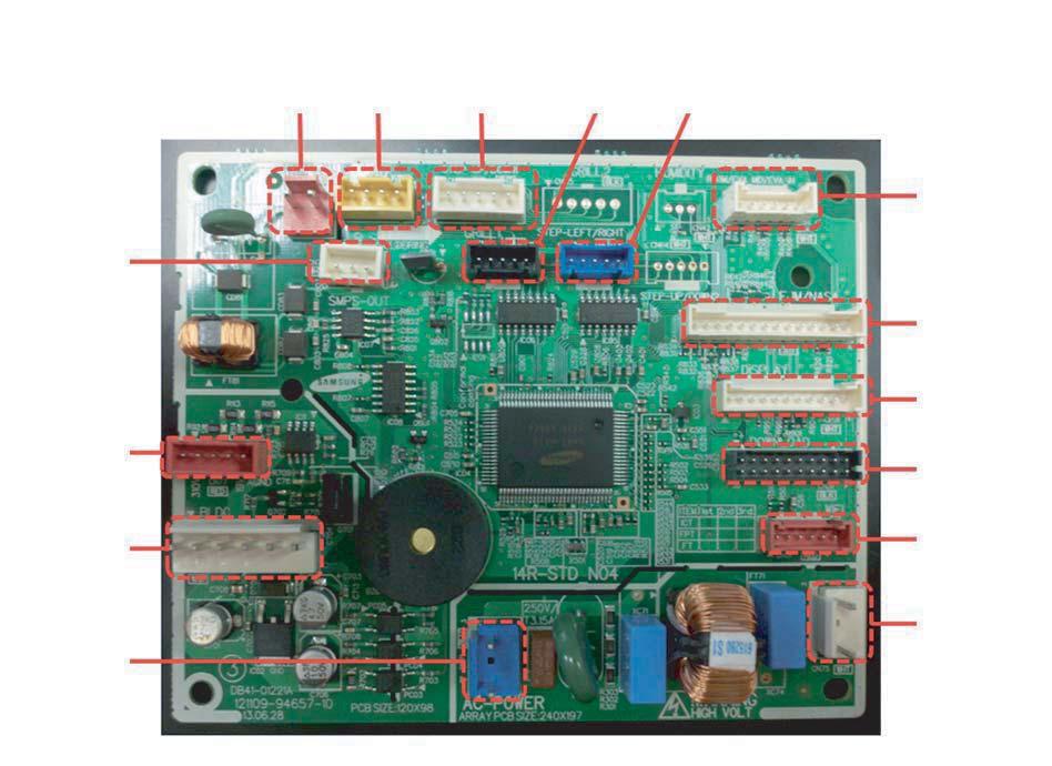
94 AJ007JNADCH/AJ009JNADCH/AJ012JNADCH/AJ018JNADCH/AJ024JNADCH 5-4 Samsung Electronics
 #2: AC POWER (N) #1: DC310V #3 : GND")
 #3: DC12V #4: COMP/OPER.")
95 AJ***NBNDCH/AA -MAIN PCB #1: EARTH #1: AC POWER (L) #2: AC POWER (N) #1: DC310V #3 : GND #4 : DC15V #5 : FAN RPM #6 : RPM FEEDBACK #1: FUSE CHECK Signal #2: GND #1: DC12V #2: ERROR OUT (GND) #3: DC12V #4: COMP/OPER. OUT (GND) Samsung Electronics 5-7
96 #1 : DC12V #2~#5: LOUVER SIGNAL #6 : DC12V #7~#10: LOUVER SIGNAL #1 : DC5V #2 : GND #3 : THERMISTOR SENSOR #4 : HUMIDITY SENSOR #1 : EVA-IN SENSOR #2 : GND #3 : EVA-OUT SENSOR #4 : GND #5 : DISCHARGE SENSOR #6 : GND #1: GND #3: DC5V #4: EEPROM_SELECT #5: EEPROM_SO #6: EEPROM_SI #7: EEPROM_CLK #1 : DC12V #2~#5: LOUVER SIGNAL #1: DRAIN PUMP (DC12V) #2: GND #1: DC12V #2: VENT SIGNAL OUTPUT(GND) #1: GND #2: GND #3: SPI SIGNAL (DC12V) #1: COM1(F1) #2: COM1(F2) #3: V1(DC12V) #4: V2(GND) #5: COM2(F3) #6: COM2(F4) 5-8 Samsung Electronics
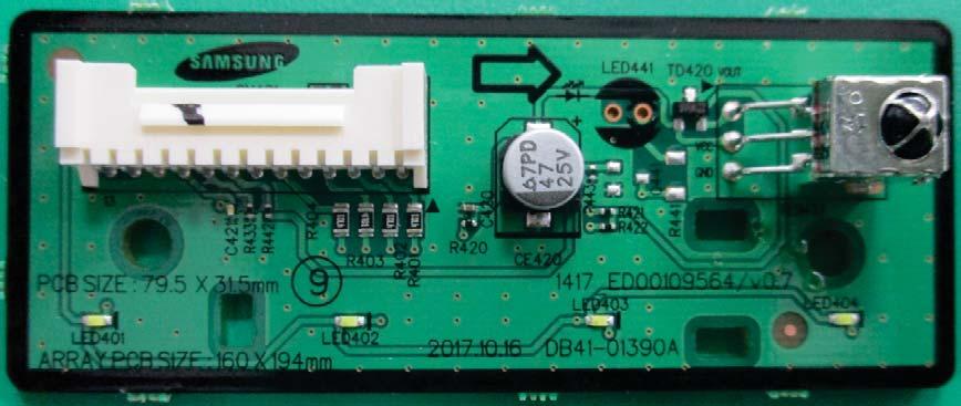
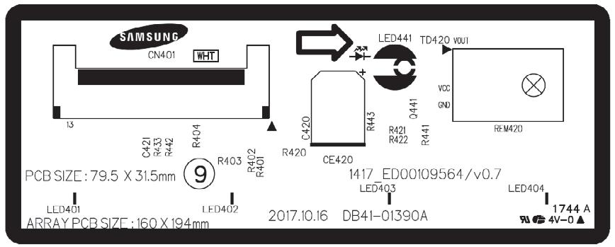
97 AJ***NBNDCH/AA -DISPLAY PCB 1 Samsung Electronics 5-9

98 5-2. Outdoor Unit AJ020JCJ2CH/AJ024JCJ3CH Samsung Electronics 5-5

99 AJ036JCJ5CH MAIN PCB CN11-ACPOWER 2 CN75-4WAY V/V 3 CN43-Sensor 4 CN81-EEV C #1~#3 : 220~240 Vac #1~#3 : 220~240 Vac #1~#2 Outdoor Temp #1~#4 EEV signal #3~#4 Cond Temp #5 DC 12V #5~#6 Discharge Temp #7~#8 OLP Temp 5 CN82-EEV B 6 CN81-EEV A 7 CN39-COMM-INV 8 CN12 - DC12V #1~#4 EEV signal #1~#4 EEV signal #1 TXD #1 DC12V #5 DC 12V #5 DC 12V #2 RXD #2 GND #3 GND #4 DC 5V #5 DC 12V #6 INV. SMPS signal 9 CN31 - COMM 10 CN33-Sub Comm 11 CN37-MICOM DOWN 12 CN35- AS PROM #1 : COM1 #1 DC12V #1~#10 MICOM DOWN #1~#7 MICOM DOWN #2 : COM2 #2 GND (AS PRO USING) #3 DC5V #4 COM1 #5 COM2 5-6 Samsung Electronics

100 AJ036JCJ5CH INVERTER PCB Samsung Electronics 5-7
 #3~#4 EVA IN B #3 DC5V #5~#6 EVA IN C")

101 AJ036JCJ5CH EMI PCB AJ036JCJ5CH HUB PCB CN33-Sub Comm 2 CN10-MICOM DOWN 3 CN10- AS PROM 4 CN52 EVA IN SENSOR #1 DC12V #1~#10 MICOM DOWN #1~#7 MICOM DOWN #1~#2 EVA IN A #2 GND (AS PRO USING) #3~#4 EVA IN B #3 DC5V #5~#6 EVA IN C #4 COM1 #7~#8 EVA IN D #5 COM2 #9~#10 EVA IN E 5 CN52 EVA OUT SENSOR 6 CN83-EEV D 7 CN84-EEV E #1~#2 EVA OUT A #1~#4 EEV signal #1~#4 EEV signal #3~#4 EVA OUT B #5 DC 12V #5 DC 12V #5~#6 EVA OUT C #7~#8 EVA OUT D #9~#10 EVA OUT E 5-8 Samsung Electronics
102 6. Wiring Diagram 6-1. INDOOR UNIT AJ009JNNDCH/AJ012JNNDCH/AJ018JNNDCH This Document can not be used without Samsung's authorization. Samsung Electronics 6-1
103 AJ007JNADCH/AJ009JNADCH/AJ012JNADCH/AJ018JNADCH/AJ024JNADCH This Document can not be used without Samsung's authorization. 6-2 Samsung Electronics
104 AJ009JNLDCH/AJ012JNLDCH/AJ018JNLDCH This Document can not be used without Samsung's authorization. Samsung Electronics 6-3
105 6-11 Samsung Electronics
106 6-2. OUTDOOR UNIT AJ020JCJ2CH/AJ024JCJ3CH 6-4 Samsung Electronics
107 AJ036JCJ5CH Samsung Electronics 6-5
108 MEMO 6-6 Samsung Electronics
109 7. Reference Sheet 7-1 Selecting Area for Installtaion Select an area for installation that is suitable to customer's needs Indoor Unit 1 Make sure that you install the indoor unit in an area providing good ventilation. It must not be blocked by an obstacle affecting the airflow near the air inlet and the air outlet. 2 Make sure that you install the indoor unit in an area allowing good air handling and endurance of vibration of the indoor unit. 3 Make sure that you install the indoor unit in an area where there is no source of heat or vapor nearby. 4 Make sure that you install the indoor unit in an area from which hot or cool air is spread evenly in a room. 5 Make sure that you install the indoor unit in an area away from TVs, audio units, cordless phones, fluorescent lighting fixtures and other electrical appliances (at least 1 meter). 6 Make sure that you install the indoor unit in an area which provides easy pipe connection with the outdoor unit, and easy drainage for condensed water. 7 Make sure that you install the indoor unit in an area which is large enough to accommodate the measurements shown in figure on the next page. It is harmful to the air conditioner if it is used in the following environments: greasy areas (including areas near machines), salty areas such as coast areas,areas where sulfuric gas is present such as hot spring areas. Contact your dealer for advice. Samsung Electronics 7-1
110 7-1-2 Outoor Unit 1 Make sure that you install the outdoor unit in area not exposed to the rain or direct sun light.(install a separate sunblind if exposed to direct sun light.) 2 Make sure that you install the outdoor unit in area allowing the good air moment, not amplifying noise or vibration, especialy to avoid disturbing neighbors. (Fix the unit firmly if it is mounted in a high place.) 3 Make sure that you install the outdoor unit in area providing the good ventilation and which is not dusty. It must not be blocked by any obstacle affecting the airflow near the air inlet and the air outlet. 4 Make sure that you install the outdoor unit in area free from animals or plants. 5 Make sure that you install the outdoor unit in area not blocking the traffic. 6 Make sure that you install the outdoor unit in area easy to drain condensed water from the indoor unit. 7 Make sure that you install the outdoor unit in area which provides easy connection within the maximum allowable length of a coolant pipe. If you install within 50m, no add a additional refrigerent : This model is chargeless within 50m. 8 Make sure that you install the outdoor unit in an area which is large enough to accommodate the measurements shown in figure on the next page. If you install the excessive length of pipe, add additional refrigerant as 20g or 10g per unit meter; refer to the table below. Model Total connecting pipe length (L) Adding refrigerant AJ020JCJ2CH AJ024JCJ3CH LT 30m LT>30m LT 40m LT>40m Chargeless (LT- 30m)x10g Chargeless (LT- 40m)x10g AJ036JCJ5CH LT 40m LT>40m Chargeless (LT- 40m)x20g Remote Control Unit 1 Make sure that you use the remote control unit in an area free from obstacles such as curtains etc, which may block signals from the remote control unit. 2 Make sure that you put the remote control unit in an area not exposed to direct sunlight, and where there is no source of heat. 3 Make sure that you use the remote control unit in an area away from TVs, audio units, cordless phones, fluorescent lighting fixtures and other electrical appliances (at least 1 meter). 7-2 Samsung Electronics
111 7-2 Connecting Up and Purging the Circuit The air in the indoor unit and in the pipe must be purged. If air remains in the refrigeration pipes, it will affect the compressor, reduce to cooling capacity and could lead to a malfunction. Refrigerant for air purging is not charged in the outdoor unit. Use Vacuum Pump as shown at the right figure. Each unit must be purged in turn. AJ020JCJ2CH/AJ024JCJ3CH/AJ036JCJ5CH 1 Check the piping connections. 2 Connect the charging hose of low pressure side of manifold gauge to the packed valve having a service port (5/8 Packed valve) as shown at the figure (Value stem: 1/2-20UNF). WARNING Make the electrical connection and leave the system into stand by mode. Do not turn on the system! This is necessary for better vacuum operation (full OPEN position of Electronic Expansion Valve - EEV -). 3 Open the valve of the low pressure side of manifold gauge counter clockwise. A B C Valve stem Vacuum Pump 4 Purge the air from the system using vacuum pump for about 30 minutes. - Close the valve of the low pressure side of manifold gauge clockwise. - Make sure that pressure gauge show -0.1MPa(-76cmHg) after about30 minutes. This procedure is very important in order to avoid gas leak. - Turn off the vacuum pump. - Remove the hose of the low pressure side of manifold gauge. Service port Stem cap 5 Set valve cork of both liquid side and gas side of packed valve to the open position. 6 Mount the valve stem nuts and the service port cap to the torque wrench. 7 Check for gas leakage. - At this time, especially check for gas leakage from the 3-way valve s stem nuts, and from the service port cap. Samsung Electronics 7-3
112 7-3 Refrigerant Refill Refill an air conditioner with refrigerant when refrigerant has been leaked at installing or using. 1) Purge air(for new installation only). 2) Turn the 3 way valve clockwise to close, connect the pressure gauge (low pressure side) to the service valve, and open the 3 way valve again. Compound gauge Suspension hook High pressure gauge 3) Connect the tank to refill with refrigerant. 4) Set the unit to cool operation mode. For mounting other and of hose when not in use Hand wheel Finger tight fittings Connected to high pressure side Charging line 5) Check the pressure indicated by the pressure gauge(low pressure side). * Standard pressure should be 8.0~9.0kg/cm 2 in a regular and high operation mode. AJ020JCJ2CH AJ024JCJ3CH AJ036JCJ5CH 6) Open the refrigerant tank and fill with refrigerant until the rated pressure is reached. * It is recommended not to pour the refrigerant in too quickly, but gradually while operating a pressure valve. 7) Stop operation of the air conditioner. 8) Close the 3 way valve, disconnect the pressure gauge, and open the 3 way valve again. 9) Close the cap of each valve. 7-4 Samsung Electronics
113 7-4 Refrigerant Adjustment Class At installation At service Connection Pipe Length Standard 30m (AJ020JCJ2CH) Standard 40m (AJ024JCJ3CH) Standard 40m (AJ036JCJ5CH) Air-Purge Method Refrigerant Adjustment Unnecessary Air-Purge Method Refrigerant Quantity refer to specification sheet Standard<Total 50m (AJ020JCJ2CH) Standard<Total 70m (AJ024JCJ3CH) Refer to the detailed conneting up and purging the circuit. (7-2 page) In case of exeeding total pipe lengh 30m, Add "10g" of refrigerant (R410A) for every 1m In case of exeeding total pipe lengh 40m, Add "10g" of refrigerant (R410A) for every 1m Purge air using a vaccume pump or an additional refrigerant cylinder. In case of exeeding total pipe lengh 30m, Add "10g" of refrigerant (R410A) for every 1m In case of exeeding total pipe lengh 40m, Add "10g" of refrigerant (R410A) for every 1m Standard<Total 80m (AJ036JCJ5CH) In case of exeeding total pipe lengh 40m, Add "20g" of refrigerant (R410A) for every 1m In case of exeeding total pipe lengh 40m, Add "20g" of refrigerant (R410A) for every 1m It would be the best choice to use the standard tube length to keep the basic quality of Room Air conditioner, for example cooling capacity, sound level, vibration level, and reliability. But, according to a certain different installation condition, the connection tube length could be changed in the recommendation length that is shown above. In this case, installer should keep the installation condition to keep the quality of Room Air conditioner. Refrigerant should be charged additionally as written above according to the change of the length of the connection tube. It needs to affect the decrease in cooling and heating capacity or of the reliability of compressor that may be caused by a lac k of refriger ant. Installation position difference between the indoor unit and the outdoor unit should not exceed over than 15 meters. When the connection pipe is been extended longer than 5 meters, it might need to change the diameter of the electrical wire to a larger size in order to keep a voltage drop for starting room air conditioner is not less than 85% of the rated voltage. And then, a voltage meter will be useful to check the rate of the voltage drop. 7-5 Flare Nut Fixing Torque Outer Diameter (D) Thickness Torque N m ft lb(kgf cm) ø6.35 mm(1/4") 0.8 mm(0.03 ") 14~ ~13.0(140~180) ø9.52 mm(3/8") 0.8 mm(0.03 ") 34~ ~31.1(350~430) ø12.70 mm(1/2") 0.8 mm(0.03 ") 49~ ~44.8(500~620) ø15.88 mm(5/8") 0.8 mm(0.03 ") 68~ ~60.0(690~830) Samsung Electronics 7-5
114 7-6 "Pump down" Procedure Pump down will be carried out when an evaporator is replaced or when the unit is relocated in another area. AJ020JCJ2CH/AJ024JCJ3CH/AJ036JCJ5CH 1) Remove the caps from the 3/8" service valve and the 5/8" service valve. 2) Turn the 5/8" service valve clockwise to close and connect a pressure gauge (low pressure side) to the service valve, and open the 5/8" service valve again. 3) Set the unit to cool operation mode. (Check if the compressor is operating.) 4) Turn the 3/8" service valve clockwise to close. 5) When the pressure gauge indicates "0" turn the 5/8" service valve clockwise to close. 6) Stop operation of the air conditioner. 7) Close the cap of each valve. 5/8" Service Valve 3/8" Service Valve Relocation of the air conditioner Refer to this procedure when the unit is relocated. 1. Carry out the pump down procedure (refer to the details of pump down ). 2. Remove the power cord. 3. Disconnect the assembly cable from the indoor and outdoor units. 4. Remove the flare nut connecting the indoor unit and the pipe. 4. At this time, cover the pipe of the indoor unit and the other pipe using a cap or vinyl plug to avoid foreign material entering. 5. Disconnect the pipe connected to the outdoor unit. 4. At this time, cover the valve of the outdoor unit and the other pipe using a cap or vinyl plug to avoid foreign material entering. 6. Make sure you do not bend the connection pipes in the middle and store together with the cables. 7. Move the indoor and outdoor units to a new location. 8. Remove the mounting plate for the indoor unit and move it to a new location. 7-6 Samsung Electronics
115 7-7 Index of Model Name Model Code (INDOOR) AJ H 009 H HN HB HN HD HC HH H/ AA H Buyer Name Code AM AJ AC AE AN AK AG Product Type Type DVM PMA CAC (USD) / ASD EHS VTL PAK (Packaged System) CHR Capacity (3 DIGIT) KW / BTU / Liter Year Code Type E 2012 F 2013 H 2014 J 2015 K 2016 M 2017 N 2018 Code S N X A B C Separator Type Normal Set (NASA) Indoor (NASA) Outdoor(NASA) Set (NASA) Indoor (Non NASA) Outdoor (No NASA) Product Type (Indoor) Code Type 1 1 WAY CST 2 2 WAY CST N MINI 4 WAY CST 4 4 WAY CST H HSP DUCT M MSP DUCT L LSP DUCT E FRESH AIR INTAKE DUCT V RAC-A3050(EEV) Q RAC-NEO FORTE(EEV) T RAC-NEO FORTE D RAC-Domestic R RAC-MALDIVE A RAC-A RAC-Crystal Code F P D S Rating Voltage Code Type A A(115V, 60hz, 1Ф) B B(220V, 60Hz, 1Ф) C C(208~230V, 60Hz) D D(200~220V, 50Hz) E E(220~240V, 50Hz) F F(208~230V, 60Hz, 3Ф) G G(380~415V, 50Hz, 3Ф) H H(380V, 60Hz, 3Ф) J J(460V, 60Hz, 3Ф) K K(220~240V, 50/60Hz, 1Ф) M M(127V, 50Hz) N N (380~415V, 50/60Hz, 3Ф) Refrigerant Code Type Refrigerant C COOLING ONLY H HEAT PUMP R410a R HEAT RECOVERY D COOLING ONLY R22 E HEAT PUMP A Cooling only R134 B Heat Pump N N/A Grade Type FLAGSHIP PREMIUM DELUXE STANDARD / can be removed from the buyer card if there are not enough digits. Samsung Electronics 7-7
116 Model Code (OUTDOOR) AJ H 020 H HJ HC HJ H2 HC HH H/ AA H Buyer Name Capacity BTU/H(*100) CMH(*10) HP(/10) WATT(*100) Year Code Type E 2012 F 2013 H 2014 J 2015 K 2016 L 2017 Product Type Code Type AM DVM AJ PMA AC CAC (USD) / ASD AE EHS AN VTL AK PAK AG CHR Code J P Code S N X A B C Feature Type IFREE JOINT MULTI PACK MULTI Separator Type Normal Set (NASA) Indoor (No NASA) Outdoor(NASA) Set (NASA) Indoor (NASA) Outdoor (No NASA) Rating Voltage Code Type A A(115V, 60hz, 1Ф) B B(220V, 60Hz, 1Ф) C C(208~230V, 60Hz) D D(200~220V, 50Hz) E E(220~240V, 50Hz) F F(208~230V, 60Hz, 3Ф) G G(380~415V, 50Hz, 3Ф) H H(380V, 60Hz, 3Ф) J J(460V, 60Hz, 3Ф) K K(220~240V, 50/60Hz, 1Ф) M M(127V, 50Hz) N N (380~415V, 50/60Hz, 3Ф) Refrigerant Code Type Refrigerant C COOLING ONLY H HEAT PUMP R410a R HEAT RECOVERY D COOLING ONLY R22 E HEAT PUMP A Cooling only R134 B Heat Pump N N/A H DVM HOME Grade Code Type 2 2 Room 3 3 Room 4 4 Room 5 5 Room N Multi Room PMA is FJM Model. / can be removed from the buyer card if there are not enough digits. 7-8 Samsung Electronics


117 7-8 Refrigerating Cycle Diagram AJ020JCJ2CH CYCLE DIAGRAM AJ024JCJ3CH CYCLE DIAGRAM Samsung Electronics 7-9
Model name: AJ009JNNDCH AJ012JNNDCH AJ018JNNDCH AJ007JNADCH AJ009JNADCH AJ012JNADCH
 Model name: AJ009JNNDCH AJ012JNNDCH AJ018JNNDCH AJ007JNADCH AJ009JNADCH AJ012JNADCH MULTI AIR CONDITIONER INDOOR UNIT AJ018JNADCH AJ024JNADCH AJ009JNLDCH AJ012JNLDCH AJ018JNLDCH OUTDOOR UNIT AJ020JCJ2CH
SERVICE Manual FREE JOINT MULTI AIR CONDITIONER
 FREE JOINT MULTI AIR CONDITIONER INDOOR UNIT MH020FPEA MH023FPEA MH026FPEA MH035FPEA MH052FPEA MH8VP2-09 MH9VP2-07 MH9VP2-2 MH026FKEA MH035FKEA MH052FDEA OUTDOOR UNIT MH8VP2X MH9VP2X MH052FXEA2 MH068FXEA4
AIR CONDITIONER. Model : 1. Precautions. 2. Product Specifications. 3. Disassembly and Reassembly. 4. Troubleshooting. 5.
 SYSTEM AIR CONDITIONER Model : INDOOR UNIT AC012MNADCH/AA AC018MNADCH/AA AC024MNADCH/AA AC030MNTDCH/AA AC036MNTDCH/AA OUTDOOR UNIT AC012KXADCH/AA AC018JXADCH/AA AC024JXADCH/AA AC030JXADCH/AA AC036JXADCH/AA
4. Disassembly and Reassembly
 4. Disassembly and Reassembly Stop operation of the air conditioner and remove the power cord before repairing the unit. 4-1 Indoor Unit 4-1-1 MH FPEA /MH VP2-1 Front Panel 1) Stop the air conditioner
SERVICE Manual SYSTEM AIR CONDITIONER INDOOR UNIT GH052EAM GH070EAM OUTDOOR UNIT UH052EAMT UH070EAMT. 1. Product Specifications
 SYSTEM AIR CONDITIONER INDOOR UNIT GH052EAM GH070EAM OUTDOOR UNIT UH052EAMT UH070EAMT SERVICE Manual SYSTEM AIR CONDITIONER CONTENTS 1. Product Specifications 2. Disassembly and Reassembly 3. Set Up the
AIR CONDITIONER 4 WAY CASSETTE SERIES. 1. Precautions. 2. Product Specifications. 3. Disassembly and Reassembly. 4. Troubleshooting. 5.
 SYSTEM AIR CONDITIONER 4 WAY CASSETTE SERIES Model : INDOOR UNIT AC018JN4DCH/AA AC024JN4DCH/AA AC030JN4DCH/AA AC036JN4DCH/AA AC042JN4DCH/AA AC048JN4DCH/AA OUTDOOR UNIT AC018JXADCH/AA AC024JXADCH/AA AC030JXADCH/AA
AJ036JCJ5** Air Conditioner. installation manual. imagine the possibilities. Thank you for purchasing this Samsung product. EN ES FR DB A-01
 AJ036JCJ5** Air Conditioner installation manual imagine the possibilities Thank you for purchasing this Samsung product. EN ES FR DB68-05013A-01 Contents Safety precautions...2 Accessories...4 Deciding
SERVICE Manual CASSETTE TYPE AIR CONDITIONER INDOOR UNIT KH026EAM KH035EAM OUTDOOR UNIT UH026EAM UH035EAM. 1. Product Specifications
 CASSETTE TYPE AIR CONDITIONER INDOOR UNIT KH026EAM KH035EAM OUTDOOR UNIT UH026EAM UH035EAM SERVICE Manual AIR CONDITIONER CONTENTS 1. Product Specifications 2. Disassembly and Reassembly 3. Block Diagrams
INSTALLATION MANUAL Duct Type Series MH FECA
 INSTALLATION MANUAL Duct Type Series MH FECA ENGLISH FRANÇAIS ESPAÑOL Free Joint Multi Air Conditioner (Cooling and Heating) E S F DB98-960A() Safety Precautions The following safety precautions must be
INSTALLATION MANUAL. Split-type Air Conditioner (Cooling and Heating) Outdoor Unit UQB09JJWC UQB12JJWC. Indoor Unit AQB09JJWC AQB12JJWC
 Outdoor Unit UQB09JJWC UQB12JJWC. Indoor Unit AQB09JJWC AQB12JJWC") AQB09JJ6WC_IM_E_2585 2006.4.17 4:26 PM Page 17 INSTALLATION MANUAL Indoor Unit AQB09JJWC AQB12JJWC Outdoor Unit UQB09JJWC UQB12JJWC ENGLISH FRANÇAIS ESPAÑOL Split-type Air Conditioner (Cooling and Heating)
AQB09JJ6WC_IM_E_2585 2006.4.17 4:26 PM Page 17 INSTALLATION MANUAL Indoor Unit AQB09JJWC AQB12JJWC Outdoor Unit UQB09JJWC UQB12JJWC ENGLISH FRANÇAIS ESPAÑOL Split-type Air Conditioner (Cooling and Heating)
AS09HPAN AS12HPAN. Split-type Air Conditioner (Cooling and Heating)
") INSTALLATION MANUAL MANUAL DE LA INSTALACIÓN MANUEL D INSTALLATION MANUALE INSTALLAZIONE MANUAL DE INSTALAÇÃO INSTALLATIONSHANDBUCH INSTALLATION MANUAL Indoor unit AS09HPAN AS12HPAN Outdoor unit AS09HPAX
INSTALLATION MANUAL MANUAL DE LA INSTALACIÓN MANUEL D INSTALLATION MANUALE INSTALLAZIONE MANUAL DE INSTALAÇÃO INSTALLATIONSHANDBUCH INSTALLATION MANUAL Indoor unit AS09HPAN AS12HPAN Outdoor unit AS09HPAX
INSTALLATION MANUAL. Split-type Air Conditioner (Cooling and Heating) Indoor Unit AQB18J6WC AQB24J2WC. Outdoor Unit UQB18J6WC UQB24J2WC
 Indoor Unit AQB18J6WC AQB24J2WC. Outdoor Unit UQB18J6WC UQB24J2WC") AQB8J6WC_IM_E_25864 2006.4.4 3:29 PM Page 7 INSTALLATION MANUAL Indoor Unit AQB8J6WC AQB24J2WC Outdoor Unit UQB8J6WC UQB24J2WC ENGLISH FRANÇAIS ESPAÑOL Split-type Air Conditioner (Cooling and Heating)
AQB8J6WC_IM_E_25864 2006.4.4 3:29 PM Page 7 INSTALLATION MANUAL Indoor Unit AQB8J6WC AQB24J2WC Outdoor Unit UQB8J6WC UQB24J2WC ENGLISH FRANÇAIS ESPAÑOL Split-type Air Conditioner (Cooling and Heating)
RC-54CA RO-50CA RC-54HA RO-50HA. SPLIT TYPE AIR CONDITIONER CASSETTE TYPE (50Hz) Indoor unit Outdoor unit
 Indoor unit Outdoor unit") SPLIT TYPE AIR CONDITIONER CASSETTE TYPE (50Hz) Indoor unit Outdoor unit RCW-54CB RO-50CA RC-54CA RO-50CA RC-54HA RO-50HA CONTENTS SPECIFICATIONS OUTLINE AND DIMENTIONS CIRCUIT DIAGRAM REFRIGERANT SYSTEM
SPLIT TYPE AIR CONDITIONER CASSETTE TYPE (50Hz) Indoor unit Outdoor unit RCW-54CB RO-50CA RC-54CA RO-50CA RC-54HA RO-50HA CONTENTS SPECIFICATIONS OUTLINE AND DIMENTIONS CIRCUIT DIAGRAM REFRIGERANT SYSTEM
INSTALLATION MANUAL. System Air Conditioner (Cooling and Heating) Cassette Type Series CH070CAV1 CH105CAV CH140CAV DB A(1) ENGLISH ESPAÑOL
 Cassette Type Series CH070CAV1 CH105CAV CH140CAV DB A(1) ENGLISH ESPAÑOL") INSTALLATION MANUAL Cassette Type Series CH070CAV1 CH105CAV CH140CAV ENGLISH FRANÇAIS ESPAÑOL System Air Conditioner (Cooling and Heating) E S F DB98-30519A(1) Safety Precautions (Carefully follow the
INSTALLATION MANUAL Cassette Type Series CH070CAV1 CH105CAV CH140CAV ENGLISH FRANÇAIS ESPAÑOL System Air Conditioner (Cooling and Heating) E S F DB98-30519A(1) Safety Precautions (Carefully follow the
OWNER S INSTRUCTIONS MANUAL DE INSTRUCCIONES MANUEL D UTILISATION ISTRUZIONI PER L USO MANUAL DE INSTRUÇÕES GEBRAUCHSANWEISUNG π Ã
 OWNER S INSTRUCTIONS MANUAL DE INSTRUCCIONES MANUEL D UTILISATION ISTRUZIONI PER L USO MANUAL DE INSTRUÇÕES GEBRAUCHSANWEISUNG π Ã Indoor unit SH09BPD SH12BPD Outdoor unit SH09BPDX SH12BPDX Split-type
AIR CONDITIONER OUTDOOR UNIT INDOOR UNIT. 1. Precautions
 MULTI AIR CONDITIONER INDOOR UNIT AJ007/009/012/018/024JNADCH AJ009/012/018JNNDCH AJ009/012/018JNLDCH OUTDOOR UNIT AJ020MCS3CH AJ024MCS4CH AJ030MCS4CH AIR CONDITIONER CONTENTS 1. Precautions 3. Disassembly
AIR CONDITIONER. 1. Precautions. 2. Product Specifications. 3. Disassembly and Reassembly. 4. Troubleshooting. 5. PCB Diagram. 6.
 SYSTEM AIR CONDITIONER GLOBAL DUCT SERIES INDOOR UNIT Model : AC018MNHDCH/AA AC024MNHDCH/AA AC030MNHDCH/AA AC036MNHDCH/AA AC042MNHDCH/AA AC048MNHDCH/AA OUTDOOR UNIT AC018JXADCH/AA AC024JXADCH/AA AC030JXADCH/AA
Safety Precautions WARNING INSTALLING THE UNIT POWER SUPPLY LINE, FUSE OR CIRCUIT BREAKER
 DH40GZM_IM_E/O_5844 3/3/06 0:4 AM Page Safety Precautions The following safety precautions must be taken when using your air conditioner. WARNING Risk of electric shock Can cause injury or death. Disconnect
CASSETTE type INVERTER MULTI AIR CONDITIONER. Models AUY12LBAB AUY14LBAB AOY18LMAK2
 INVERTER MULTI AIR CONDITIONER CASSETTE type Models Indoor unit AUY12LBAB AUY14LBAB Outdoor unit AOY18LMAK2 CONTENTS SPECIFICATIONS..................... 1 OUTLINE AND DIMENSIONS........... 2 REFRIGERANT
AIR CONDITIONER OUTDOOR UNIT AM036NXMDCR AM048NXMDCR AM053NXMDCR AM060NXMDCR. Product Specifications. Disassembly and Reassembly
 SYSTM AIR CONDITIONR OUTDOOR UNIT AM036NXMDCR AM048NXMDCR AM053NXMDCR AM060NXMDCR AIR CONDITIONR CONTNTS Product Specifications Disassembly and Reassembly Refrigerant pipe installation Troubleshooting
DUCT type. Большая библиотека технической документации каталоги, инструкции, сервисные мануалы, схемы.
 SPLIT TYPE AIR CONDITIONER (50Hz) DUCT type Models Indoor unit Outdoor unit RD-25CA RD-25HA RD-30CA RD-30HA RO-25CA RO-25HA RO-30CA RO-30HA C O N T E N T S SPECIFICATIONS.............................................
INSTALLATION MANUAL MANUAL DE INSTALACIÓN MANUEL D INSTALLATION
 INSTALLATION MANUAL MANUAL DE INSTALACIÓN MANUEL D INSTALLATION Indoor Unit AQ8A9(0)RCF AQ24A(2)RC Outdoor Unit UQ8A9(0)RCF UQ24A(2)RC ENGLISH ESPAÑOL FRANÇAIS Split Type Air Conditioner (Cool and Heat)
FH052EAMT FH070EAMT E S F I P D G R DB A(2) ENGLISH ESPAÑOL FRANÇAIS ITALIANO PORTUGUÊS DEUTSCH RUSSIAN E HNIKA
 ENGLISH ESPAÑOL FRANÇAIS ITALIANO PORTUGUÊS DEUTSCH RUSSIAN E HNIKA") INSTALLATION MANUAL MANUAL DE INSTALACIÓN MANUEL D INSTALLATION MANUALE D INSTALLZIONE MANUAL DE INSTALAÇÃO INSTALLATIONS-HANDBUCH E EIPI IO E KATA TA H àçëíêìäñàü èé ìëíäçéçäö FH052EAMT FH070EAMT ENGLISH
INSTALLATION MANUAL MANUAL DE INSTALACIÓN MANUEL D INSTALLATION MANUALE D INSTALLZIONE MANUAL DE INSTALAÇÃO INSTALLATIONS-HANDBUCH E EIPI IO E KATA TA H àçëíêìäñàü èé ìëíäçéçäö FH052EAMT FH070EAMT ENGLISH
USER S MANUAL AQV09J Series AQV12J Series AQV18J Series AQV24J Series
 USER S MANUAL AQV09J Series AQV12J Series AQV18J Series AQV24J Series FRANÇAIS ENGLISH ESPAÑOL Split-type Air Conditioner (Cooling and Heating) E S F DB98-27555A(1) Safety Precautions Register your product
CASSETTE type INVERTER MULTI AIR CONDITIONER
 INVERTER MULTI AIR CONDITIONER CASSETTE type Models Indoor unit AUY12LBAB AUY14LBAB Outdoor unit AOY18LMAK2 CONTENTS SPECIFICATIONS..................... 1 OUTLINE AND DIMENSIONS........... 2 REFRIGERANT
DC INVERTER MULTI-SYSTEM AIR CONDITIONER
 TECHNICAL & SERVICE MANUAL OUTDOOR UNIT : CU-3KE19NBU CU-4KE24NBU CU-4KE31NBU DC INVERTER MULTI-SYSTEM AIR CONDITIONER Capacity at 0V 19,100 BTU/h,200 BTU/h 30,600 BTU/h Outdoor Model No. CU-3KE19NBU CU-4KE24NBU
SERVICE Manual AIR CONDITIONER AW0719 AW Precautions. 2. Product Specifications. 3. Operating Instructions and Installation
 ROOM AIR CONDITIONER AW079 AW089 SERVICE Manual AIR CONDITIONER CONTENTS. Precautions 2. Product Specifications 3. Operating Instructions and Installation 4. Disassembly and Reassembly 5. Troubleshooting
SYSTEM AIR CONDITIONER
 SYSTEM AIR CONDITIONER AHU SERIES Model : INDOOR UNIT AC018KNZDCH/AA AC024KNZDCH/AA AC030KNZDCH/AA AC036KNZDCH/AA AC042KNZDCH/AA AC048KNZDCH/AA AC054KNZDCH/AA OUTDOOR UNIT AC018JXADCH/AA AC024JXADCH/AA
E S F I P D G DB A(1) ENGLISH ESPAÑOL FRANÇAIS ITALIANO PORTUGUÊS DEUTSCH E HNIKA
 ENGLISH ESPAÑOL FRANÇAIS ITALIANO PORTUGUÊS DEUTSCH E HNIKA") INSTALLATION MANUAL MANUAL DE LA INSTALACIÓN MANUEL D INSTALLATION MANUALE INSTALLAZIONE MANUAL DE INSTALAÇÃO INSTALLATIONSHANDBUCH E XEIPI IO E KATA TA H Indoor unit MH023FWEA MH026FWEA MH035FWEA MH052FWEA
INSTALLATION MANUAL MANUAL DE LA INSTALACIÓN MANUEL D INSTALLATION MANUALE INSTALLAZIONE MANUAL DE INSTALAÇÃO INSTALLATIONSHANDBUCH E XEIPI IO E KATA TA H Indoor unit MH023FWEA MH026FWEA MH035FWEA MH052FWEA
SPLIT TYPE ROOM AIR CONDITIONER FLOOR CONSOLE / UNDER CEILING DUAL TYPE
 SPLIT TYPE ROOM AIR CONDITIONER FLOOR CONSOLE / UNDER CEILING DUAL TYPE Indoor unit ABYF8LAT ABYF8LAT ABYF8LAT ABYF8LAT ABYF8LBT ABYF8LBT ABYFLAT ABYFLAT ABYFLAT ABYFLAT ABYFLBT ABYFLBT Outdoor unit AOYA8LACL
CASSETTE type SPLIT TYPE AIR CONDITIONER. (60Hz) AUU18RCLX AUU24RCLX AUU36RCLX AUU42RCLX AOU18RLX AOU24RLX AOU36RLX AOU42RLX CONTENTS.
 AUU18RCLX AUU24RCLX AUU36RCLX AUU42RCLX AOU18RLX AOU24RLX AOU36RLX AOU42RLX CONTENTS.") SPLIT TYPE AIR CONDITIONER CASSETTE type (60Hz) Models Indoor unit AUU8RCLX AUURCLX AUU6RCLX AUURCLX Outdoor unit AOU8RLX AOURLX AOU6RLX AOURLX CONTENTS SPECIFICATIONS... DIMENSIONS... REFRIGERANT SYSTEM
SPLIT TYPE AIR CONDITIONER CASSETTE type (60Hz) Models Indoor unit AUU8RCLX AUURCLX AUU6RCLX AUURCLX Outdoor unit AOU8RLX AOURLX AOU6RLX AOURLX CONTENTS SPECIFICATIONS... DIMENSIONS... REFRIGERANT SYSTEM
OWNER S INSTRUCTIONS MANUAL DE INSTRUCCIONES MANUEL D UTILISATION ISTRUZIONI PER L USO MANUAL DE INSTRUÇÕES GEBRAUCHSANWEISUNG
 OWNER S INSTRUCTIONS MANUAL DE INSTRUCCIONES MANUEL D UTILISATION ISTRUZIONI PER L USO MANUAL DE INSTRUÇÕES GEBRAUCHSANWEISUNG π Ã àçëíêìäñàü èéãúáéçäíöãü MH026FPEA MH035FPEA MH052FPEA ENGLISH ESPAÑOL
DESIGN & TECHNICAL MANUAL
 AIR CONDITIONER Wall mounted type DESIGN & TECHNICAL MANUAL INDOOR ASYG18KLCA ASYG24KLCA OUTDOOR AOYG18KLTA AOYG24KLTA DR_AS069EF_01 2018.03.16 Notices: Product specifications and design are subject to
WALL MOUNTED type SPLIT TYPE ROOM AIR CONDITIONER CONTENTS. Models
 SPLIT TYPE ROOM AIR CONDITIONER WALL MOUNTED type Models Indoor unit ASY9USCCW ASY9USCCW ASY12USCCW Outdoor unit AOY9USCC AOY9UFCC AOY12USCC CONTENTS SPECIFICATIONS................................... 1
Air Conditioner. user installation & manual manual. imagine the possibilities
 ARFSSSBWK Series ARFSSSCUR AJ JNADCH Series Air Conditioner user installation & manual manual This manual is made with 100% recycled paper. imagine the possibilities Thank you for purchasing this Samsung
AIR CONDITIONER. 1. Precautions. 2. Product Specifications. 3. Disassembly and Reassembly. 4. Troubleshooting. 5. PCB Diagram. 6.
 SYSTEM AIR CONDITIONER MA DUCT SERIES Model : INDOOR UNIT AC018JNHDCH/AA AC024JNHDCH/AA AC030JNHDCH/AA AC036JNHDCH/AA AC042JNHDCH/AA AC048JNHDCH/AA OUTDOOR UNIT AC018JXADCH/AA AC024JXADCH/AA AC030JXADCH/AA
Air Conditioner. installation manual. imagine the possibilities. Wired Remote Control MWR-WE10. Thank you for purchasing this Samsung product.
 Control MWR-WE10 Air Conditioner installation manual imagine the possibilities Thank you for purchasing this Samsung product. E S F I P D G R A DB98-32811A(2) Safety Information This installation manual
Service Manual & Installation Manual
 GE Consumer & Industrial Appliances Service Manual & Installation Manual Split System Air Conditioner Model numbers: GE AIR F24 GE AIR F34 GE AIR F41 1 2 3 Introduction and Features Model Remarks GE AIR
DESIGN & TECHNICAL MANUAL
 AIR CONDITIONER Wall mounted type DESIGN & TECHNICAL MANUAL INDOOR ASYG07LMCE ASYG09LMCE ASYG12LMCE ASYG14LMCE OUTDOOR AOYG07LMCE AOYG09LMCE AOYG12LMCE AOYG14LMCE DR_AS037EF_01 2016.12.05 Notices: Product
USER S MANUAL AQV09V A Series AQV12V A Series AQV18V A Series AQV24V A Series
 USER S MANUAL AQV09V A Series AQV12V A Series AQV18V A Series AQV24V A Series ENGLISH FRANÇAIS ESPAÑOL Split - type Air Conditioner (Cooling and Heating) E S F DB98-27559A(1) Contents PREPARATION Safety
INSTALLATION MANUAL MANUAL DE INSTALACIÓN MANUEL D INSTALLATION MANUALE D INSTALLZIONE MANUAL DE INSTALAÇÃO INSTALLATIONS-HANDBUCH
 INSTALLATION MANUAL MANUAL DE INSTALACIÓN MANUEL D INSTALLATION MANUALE D INSTALLZIONE MANUAL DE INSTALAÇÃO INSTALLATIONS-HANDBUCH E XEIPI IO E KATA TA H àçëíêìäñàü èé ìëíäçéçäö Wired Remote Controller
SPLIT TYPE ROOM AIR CONDITIONER CEILING TYPE (60Hz)
") SPLIT TYPE ROOM AIR CONDITIONER CEILING TYPE (60Hz) Indoor unit MS6YF Outdoor unit MR6YF CONTENTS SPECIFICATIONS... OUTLINE AND DIMENSIONS... REFRIGERANT SYSTEM DIAGRAM.... CIRCUIT DIAGRAM... INDOOR PCB
SPLIT TYPE ROOM AIR CONDITIONER CEILING TYPE (60Hz) Indoor unit MS6YF Outdoor unit MR6YF CONTENTS SPECIFICATIONS... OUTLINE AND DIMENSIONS... REFRIGERANT SYSTEM DIAGRAM.... CIRCUIT DIAGRAM... INDOOR PCB
DESIGN & TECHNICAL MANUAL
 AIR CONDITIONER Wall mounted type DESIGN & TECHNICAL MANUAL INDOOR ASYG07KGTA ASYG09KGTA ASYG12KGTA ASYG14KGTA OUTDOOR AOYG07KGCA AOYG09KGCA AOYG12KGCA AOYG14KGCA DR_AS049EF_02 2017.10.11 Notices: Product
INSTALLATION MANUAL MANUAL DE INSTALACIÓN MANUALE D INSTALLAZIONE MANUAL DE INSTALAÇÃO MANUEL D INSTALLATION INSTALLATIONS-HANDBUCH
 Indoor Unit AQ07A1(A2)VE AQ09A1(A2)VE/B AQ12A1(A2)VE/B SH07YA0 SH09YA0 SH12YA0 SH07YAA(B) SH09YAA(B) SH12YAA(B) SH09ZV SH12ZV INSTALLATION MANUAL MANUAL DE INSTALACIÓN MANUALE D INSTALLAZIONE MANUAL DE
YC ON-OFF SERIES. Service Manual
 YC ON-OFF SERIES Service Manual CONTENTS 1. Precaution... 3 1.1 Safety Precaution... 3 1.2 Warning... 3 2. Model Lists... 6 3. Dimension... 7 3.1 Indoor Unit... 7 3.2 Outdoor Unit... 11 4. Refrigerant
Installation Instructions
 40MAQ High Wall Ductless Split System Sizes 09 to 36 Installation Instructions NOTE: Read the entire instruction manual before starting the installation TABLE OF CONTENTS PAGE SAFETY CONSIDERATIONS 2 PARTS
Air conditioner. Installation manual
 ir conditioner Installation manual J MCS CH Thank you for purchasing this Samsung air conditioner. efore operating this unit, please read this manual carefully and retain it for future reference. Contents
E XEIPI IO E KATA TA H
 INSTALLATION MANUAL MANUAL DE INSTALACIÓN MANUEL D INSTALLATION MANUALE D INSTALLZIONE MANUAL DE INSTALAÇÃO INSTALLATIONS-HANDBUCH E XEIPI IO E KATA TA H Indoor unit AQ07P8GE AQ07PBGE AQ07S8GE AQ07SBGE
CEILING type (60Hz) SPLIT TYPE ROOM AIR CONDITIONER CONTENTS. Models
 SPLIT TYPE ROOM AIR CONDITIONER CONTENTS. Models") SPLIT TYPE ROOM AIR CONDITIONER CEILING type (60Hz) Models Indoor unit ABU6RSLX Outdoor unit AOU6RLX CONTENTS SPECIFICATIONS....................... OUTLINE AND DIMENSIONS............. REFRIGERANT SYSTEM
SPLIT TYPE ROOM AIR CONDITIONER CEILING type (60Hz) Models Indoor unit ABU6RSLX Outdoor unit AOU6RLX CONTENTS SPECIFICATIONS....................... OUTLINE AND DIMENSIONS............. REFRIGERANT SYSTEM
SPLIT-TYPE AIR CONDITIONER
 SPLIT-TYPE AIR CONDITIONER INDOOR UNIT Basic : AQB09JJWC AQB12JJWC Model : AQV09JA AQV12JA Model Code : AQV09JA AQV12JA OUTDOOR UNIT AQV09JAX AQV12JAX AIR CONDITIONER THE FEATURE OF PRODUCT High Energy
C&H NORDIC Commercial 4 SERVICE MANUAL
 C&H NORDIC Commercial 4 SERVICE MANUAL CONTENTS PRODUCT...3 1 MODELS LIST... 3 1.1 Outdoor Unit.... 3 1.2 Indoor Unit.... 4 2 PRODUCT DATA.... 5 2.1 Product Data of Indoor Unit... 5 2.2 Operation Range...
INSTALLATION MANUAL RHF025EE Series RHF035EE Series RHF050EE Series RHF080EE Series RHF100EE Series
 INSTALLATION MANUAL RHF025EE Series RHF035EE Series RHF050EE Series RHF080EE Series RHF100EE Series PORTUGUÊS ENGLISH ITALIANO ESPAÑOL FRANÇAIS ERV (Energy Recovery Ventilator) DEUTSCH E S F I P D DB98-27512A(3)
DESIGN & TECHNICAL MANUAL
 AIR CONDITIONER Wall mounted type DESIGN & TECHNICAL MANUAL For Extra Cold Climate Area INDOOR ASU18RLF ASU24RLF OUTDOOR AOU18RLXFWH AOU24RLXFWH DR_AS014EF_04 2017.03.10 Notices: Product specifications
INVERTER SPLIT - TYPE
 INVERTER SPLIT - TYPE ISSUE No 2 DATE 04/09/08 P/No 2020323A2868 CONTENTS SAFETY PRECAUTIONS Warning 2 Operating temperature 2 BEFORE INSTALLATION Tools needed for installation 3 Items required for installing
DC INVERTER SPLIT SYSTEM AIR CONDITIONER
 AIR CONDITIONER TECHNICAL & SERVICE MANUAL KS1872 + C1872 + CL1872 KS2472 + C2472 + CL2472 FILE NO. Destination: North America DC INVERTER SPLIT SYSTEM AIR CONDITIONER Indoor Model No. KS1872 KS2472 Product
Room Air Conditioner CP06 & CP08. Chill 115 Volts. Service & Parts Manual THE EXPERTS IN ROOM AIR CONDITIONING _02
 Room Air Conditioner Service & Parts Manual 2014-2015 CP06 & CP08 Chill 115 Volts THE EXPERTS IN ROOM AIR CONDITIONING 93011401_02 CONTENTS 1. PREFACE 1.1 SAFETY PRECAUTIONS...2 1.2 INSULATION RESISTANCE
V ~, 50Hz 1Ph. High Wall Split Systems Heat Pump 9K - 12K - 18K - 24K - 28K. Auto. Auto Fan Speed. Auto. Smart LCD Wireless Control.
 HFC4 1 0 A 0-40V ~, 0Hz 1Ph High Wall Split Systems Heat Pump 9K - 1K - 18K - 4K - 8K R-410A Compressor Super Quiet AMS Anti-dust Filters Auto Fan Speed Timer Functions Defrost Protection Smart LCD Wireless
Split-type Room Air Conditioner (Cool) Aire acondicionado doméstico sistema Split (Refrigeración) Climatiseur de type Séparé (Refroidissement)
 Aire acondicionado doméstico sistema Split (Refrigeración) Climatiseur de type Séparé (Refroidissement)") OWNER S INSTRUCTIONS MANUAL DE INSTRUCCIONES MANUEL D UTILISATION Indoor unit AS24A5(6)RCD AST24A5(6)RB(E)D SC24AC5(6) SC24TA5(6)(8)D AS18A9(0)RB(C)(D)(E)D SC18ZA9(0)D SC18AC9(0) AS12AA(B)MB(E) SC12ZAA(B)
OWNER S INSTRUCTIONS MANUAL DE INSTRUCCIONES MANUEL D UTILISATION Indoor unit AS24A5(6)RCD AST24A5(6)RB(E)D SC24AC5(6) SC24TA5(6)(8)D AS18A9(0)RB(C)(D)(E)D SC18ZA9(0)D SC18AC9(0) AS12AA(B)MB(E) SC12ZAA(B)
SERVICE Manual CEILING TYPE AIR CONDITIONER INDOOR UNIT FH052EZA FH070EZA OUTDOOR UNIT FH052EZX FH070EZX. 1. Product Specifications
 CEILING TYPE AIR CONDITIONER INDOOR UNIT FH052EZA FH070EZA OUTDOOR UNIT FH052EZX FH070EZX SERVICE Manual AIR CONDITIONER CONTENTS 1. Product Specifications 2. Trouble Shooting 3. Block Diagrams 4. Disassembly
AUTO COOL DRY FAN SPEED AIR SWING OFF ON TIMER TIMER OFF/ON FAN SPEED MODE TEMP AIR SWING TIMER ON SET OFF CANCEL AC RC SET CHECK CLOCK RESET
 AUTO COOL DRY MODE TIMER ON OFF TIMER OFF/ON TEMP ON TIMER FAN SPEED AIR SWING SET 1 2 3 FAN SPEED AIR SWING OFF CANCEL AC RC SET CHECK CLOCK RESET Order No: PAPAMY1611008CE Indoor Unit CS-MPS9SKH CS-MPS12SKH
FLOOR CONSOLE / UNDER CEILING DUAL type (60Hz)
") SPLIT TYPE ROOM AIR CONDITIONER FLOOR CONSOLE / UNDER CEILING DUAL type (60Hz) Models Indoor unit MSYF Outdoor unit MRUYF CONTENTS SPECIFICATIONS... OUTLINE AND DIMENSIONS... REFRIGERANT SYSTEM DIAGRAM...
SPLIT TYPE ROOM AIR CONDITIONER FLOOR CONSOLE / UNDER CEILING DUAL type (60Hz) Models Indoor unit MSYF Outdoor unit MRUYF CONTENTS SPECIFICATIONS... OUTLINE AND DIMENSIONS... REFRIGERANT SYSTEM DIAGRAM...
SERVICE MANUAL 42QHF009DS* 42QHF012DS* 42QHF018DS* 42QHF022DS* 38QUS009DS* 38QUS012DS* 38QUS018DS* 38QUS022DS* Indoor unit.
 SERVICE MANUAL Indoor unit Outdoor unit 42QHF009DS* 42QHF012DS* 42QHF018DS* 42QHF022DS* 38QUS009DS* 38QUS012DS* 38QUS018DS* 38QUS022DS* INDEX PART1 GENERAL INFORMATION PART2 ELECTRICAL DIAGRAM PART3 TROUBLE
TECHNICAL & SERVICE MANUAL WINDOW TYPE AIR CONDITIONER SA 123A FILE NO. SA 123A REFERENCE NO. SM700513
 TECHNICAL & SERVICE MANUAL SA 123A FILE NO. WINDOW TYPE AIR CONDITIONER Model No. Product Code No. Destination SA-123A 1 851 006 95 Australia SA 123A REFERENCE NO. SM700513 IMPORTANT! Please Read Before
FLOOR CONSOLE / UNDER CEILING DUAL type
 SPLIT TYPE ROOM AIR CONDITIONER FLOOR CONSOLE / UNDER CEILING DUAL type Models Indoor unit ABU8RULX ABURULX Outdoor unit AOU8RLX AOURLX CONTENTS SPECIFICATIONS... OUTLINE AND DIMENSIONS... REFRIGERANT
REFRIGERATOR SIDE BY SIDE TYPE CONTENTS REFRIGERATOR MODEL NAME : RH22H9010SR RH29H9000SR MODEL CODE : RH22H9010SR/AA RH29H9000SR/AA
 REFRIGERATOR SIDE BY SIDE TYPE MODEL NAME : RH22H9010SR RH29H9000SR MODEL CODE : RH22H9010SR/AA RH29H9000SR/AA REFRIGERATOR CONTENTS 1. PRECAUTIONS(SAFETY WARNINGS) 5 2. PRODUCT SPECIFICATIONS 8 3. DISASSEMBLY
TECHNICAL & SERVICE MANUAL WINDOW TYPE AIR CONDITIONER SA 183A FILE NO. SA 183A REFERENCE NO. SM Destination Australia SA-183A
 TECHNICAL & SERVICE MANUAL SA 183A FILE NO. WINDOW TYPE AIR CONDITIONER Model No. Product Code No. SA-183A 1 851 006 96 Destination Australia SA 183A REFERENCE NO. SM700514 IMPORTANT! Please Read Before
DESIGN & TECHNICAL MANUAL
 AIR CONDITIONER Wall Mounted type DESIGN & TECHNICAL MANUAL INDOOR AS A09LEC AS A12LEC OUTDOOR AO R09LECN AO R12LECN 1.INDOOR UNIT : AS A09LEC AS A12LEC DTR_AS047E_01 2010.10.05 1. INDOOR UNIT CONTENTS
SiBE04-808_C. Service Manual. Inverter Pair Wall Mounted Type G-Series. [Applied Models] Inverter Pair : Cooling Only Inverter Pair : Heat Pump
![SiBE04-808_C. Service Manual. Inverter Pair Wall Mounted Type G-Series. [Applied Models] Inverter Pair : Cooling Only Inverter Pair : Heat Pump](/thumbs/88/114609417.jpg "SiBE04-808_C. Service Manual. Inverter Pair Wall Mounted Type G-Series. [Applied Models] Inverter Pair : Cooling Only Inverter Pair : Heat Pump") Service Manual Inverter Pair Wall Mounted Type G-Series [Applied Models] Inverter Pair : Cooling Only Inverter Pair : Heat Pump Inverter Pair Wall Mounted Type G-Series Cooling Only Indoor Unit FTXS20G2V1B
Service Manual Inverter Pair Wall Mounted Type G-Series [Applied Models] Inverter Pair : Cooling Only Inverter Pair : Heat Pump Inverter Pair Wall Mounted Type G-Series Cooling Only Indoor Unit FTXS20G2V1B
SERVICE MANUAL CLASSIC PLUS 14 SERIAL NUMBER FROM JANUARY 2008 (0108) TO PRESENT. DocID: 00G00019E
 TO PRESENT. DocID: 00G00019E") SERVICE MANUAL CLASSIC PLUS 14 SERIAL NUMBER FROM JANUARY 2008 (0108) TO PRESENT DocID: 00G00019E 2008 DENSO SALES CALIFORNIA, INC. All rights reserved. This book may not be reproduced or copied, in whole
SERVICE MANUAL CLASSIC PLUS 14 SERIAL NUMBER FROM JANUARY 2008 (0108) TO PRESENT DocID: 00G00019E 2008 DENSO SALES CALIFORNIA, INC. All rights reserved. This book may not be reproduced or copied, in whole
Owner s Manual Super-Slim Four-Way Cassette
 CASSETTE- TYPE AIR CONDITIONER Owner s Manual Super-Slim Four-Way Cassette IMPORTANT NOTE: Read this manual carefully before installing or operating your new air conditioning unit. Make sure to save this
WALL MOUNTE SPLIT T YPE ROOM AIR CONDITIONER. type. Models. Models. Outdoor Unit Serial No. Starting with T ( Compressor Recipro type )
") SPLIT T YPE ROOM AIR CONDITIONER WALL MOUNTE type Models Outdoor Unit Serial No. Starting with T000001 ( Compressor Recipro type ) Indoor unit ASU18C1 ASU18R1 ASU24C1 ASU24R1 ASU30C1 Outdoor unit AOU18C1
SPLIT T YPE ROOM AIR CONDITIONER WALL MOUNTE type Models Outdoor Unit Serial No. Starting with T000001 ( Compressor Recipro type ) Indoor unit ASU18C1 ASU18R1 ASU24C1 ASU24R1 ASU30C1 Outdoor unit AOU18C1
A single answer for multiple zones.
 FJM - Free Joint Multi A single answer for multiple zones. More comfort with less. This powerful unit supports up to five indoor units for multi-zone control with one outdoor unit. It s also available
INSTALLATION MANUAL MANUAL DE INSTALACIÓN MANUEL D INSTALLATION MANUALE D INSTALLZIONE MANUAL DE INSTALAÇÃO INSTALLATIONS-HANDBUCH
 INSTALLATION MANUAL MANUAL DE INSTALACIÓN MANUEL D INSTALLATION MANUALE D INSTALLZIONE MANUAL DE INSTALAÇÃO INSTALLATIONS-HANDBUCH E EIPI IO E KATA TA H àçëíêìäñàü èé ìëíäçéçäö MH023FEEA MH026FEEA MH035FEEA
Service Manual & Installation Manual
 GE Consumer & Industrial Appliances Service Manual & Installation Manual Split System Air Conditioner Model numbers: GE AIR C18 GE AIR C24 GE AIR C34 GE AIR C41 1 Introduction and Features Model Remarks
TECHNICAL & SERVICE MANUAL. Ceiling Concealed
 STAND BY DEFROST CHECK CLOCK ON OFF NOT AVAILABLE FILTER CHECK MODE TEST RUN FUNCTION SPLIT-TYPE, HEAT PUMP AIR CONDITIONERS TECHNICAL & SERVICE MANUAL Series SEZ Ceiling Concealed R40A.OC0 REVISED EDITION-A
Product Data FEATURES AND BENEFITS. QHF 50Hz Heat Pump Inverter Single Phase 2.5kW to 8.0kW
 0Hz Heat Pump Inverter Single Phase.kW to 8.0kW turn to the experts Product Data FEATURES AND BENEFITS AVAILABLE SIZES: Nominal capacity are available from.kw through 8.0kW to meet the needs of residential
Service Manual. Room Air Conditioner Split Wall-Mounted Type. Applies to: HSG-09HRN1 HSG-12HRN1 HSG-18HRN1 HSG-24HRN1
 Service Manual Room Air Conditioner Split Wall-Mounted Type Applies to: HSG-09CRN1 HSG-12CRN1 HSG-18CRN1 HSG-24CRN1 HSG-09HRN1 HSG-12HRN1 HSG-18HRN1 HSG-24HRN1 NOTE: Please read this first before servicing
CASSETTE type (50Hz) SPLIT TYPE AIR CONDITIONER. Models Indoor unit Outdoor unit
 SPLIT TYPE AIR CONDITIONER. Models Indoor unit Outdoor unit") SPLIT TYPE AIR CONDITIONER CASSETTE type (50Hz) Models Indoor unit Outdoor unit RCW-12HA RO-12HB C O N T E N T S SPECIFICATIONS........................................ 1 OUTLINE AND DIMENSIONS..............................
SPLIT TYPE AIR CONDITIONER CASSETTE type (50Hz) Models Indoor unit Outdoor unit RCW-12HA RO-12HB C O N T E N T S SPECIFICATIONS........................................ 1 OUTLINE AND DIMENSIONS..............................
High Wall Split Systems Cool Only 9K - 12K - 18K - 24K. Auto. Auto. Fan Speed. Smart LCD Wireless Control. Auto Mode.
 HFC4 1 0 A 0-40V ~, 0Hz 1Ph High Wall Split Systems Cool Only 9K - 1K - 18K - 4K R-410A IAQ $ Auto Auto Fan Speed Timer s Easy Flexible Installation Smart LCD Wireless Control Auto Mode Auto Restart Easy
SERVICE MANUAL K LIGHT COMMERCIAL
 SERVICE MANUAL 36 48 60K LIGHT COMMERCIAL Cassette indoor unit Under-ceiling indoor unit Ducted indoor unit 42QTD036DS* 42QTD048DS* 42QTD060DS* 42QZL036DS* 42QZL048DS* 42QZL060DS* 42QSM036DS* 42QSM048DS*
TECHNICAL DATA & SERVICE MANUAL MTF94C5TAA
 TECHNICAL DATA & SERVICE MANUAL MTF94C5TAA 0.8180.472.0 07/2005 Page 1. SPECIFICATIONS 3 1-1 Unit Specifications 3 1-2 Major Component Specifications 4 2. DIMENSIONAL DATA 6 2-1 Unit Dimensions 6 3. ELECTRICAL
Ductless Split Air Conditioner
 Ductless Split Air Conditioner Service Manual Indoor HSU09VHG(DB)-W HSUVHG(DB)-W HSU8VHH(DB)-W HSUVHG(DB)-W Outdoor HSU09VHG(DB)-G HSUVHG(DB)-G HSU8VHH(DB)-G HSUVHG(DB)-G Design may vary by model number.
INSTALLATION AND USER MANUAL
 INSTALLATION AND USER MANUAL t Thank you for choosing Aqua inverter heat pump. This manual provides you necessary information for optimal use and maintenance, please read it carefully and keep it for subsequent
Room Air Conditioner Service and Parts Manual
 Cool Dry Temp Mode Room Air Conditioner Service and Parts Manual F Fan Speed hr Timer 0n 0ff Money Saver Fan Only Auto Swing Power CP06 CP08 93011401_01 CONTENTS 1. PREFACE 1.1 SAFETY PRECAUTIONS...2 1.2
THROUGH-WALL AIR-TO-AIR HEAT PUMP AND AIR CONDITIONER. Instruction Manual. Model AMB-12H
 THROUGH-WALL AIR-TO-AIR HEAT PUMP AND AIR CONDITIONER Instruction Manual Model AMB-12H PLEASE READ THIS INSTRUCTION MANUAL CAREFULLY BEFORE USING THIS UNIT. Table of Contents 1. SAFETY WARNINGS 2 2. CONSTRUCTION...
Air Conditioner installation manual
 Air Handling Unit Application Kit MXDK025AN MXDK050AN MXDK075AN MXDK100AN MXDX000AN Air Conditioner installation manual imagine the possibilities Thank you for purchasing this Samsung product. EN DB6803711A04
Hi - Wall Split Systems 12K - 18K - 24K
 R22 220-240V ~ 50Hz 1Ph Hi - Wall Split Systems 12K - 18K - 24K Technology Tropical Compressor Super Quiet Auto Auto Fan Speed Auto Restart Function Self diagnostic function Active Carbon Electrostatic
Air Conditioner Service Manual
 Air Conditioner Service Manual Большая библиотека технической документации http://splitoff.ru/tehn-doc.html каталоги, инструкции, сервисные мануалы, схемы. 2 MODEL: AC-S13CEGL1 3 CONTENTS TECHNICAL SPECIFICATION...
A single answer for multiple zones.
 Free Joint Multi (FJM) A single answer for multiple zones. More comfort with less. This powerful unit supports two to five indoor units for multi-zone control with one outdoor unit. It s also available
TECHNICAL & SERVICE MANUAL WINDOW TYPE AIR CONDITIONER SA 128S5 FILE NO. SA 128S5 REFERENCE NO. SM700338
 TECHNICAL & SERVICE MANUAL SA 128S5 FILE NO. WINDOW TYPE AIR CONDITIONER Model No. Product Code No. Destination SA-128S5-A 1 851 004 09 General (50Hz) & Europe SA 128S5 REFERENCE NO. SM700338 IMPORTANT!
Single Zone Air Conditioner SVC MANUAL (Exploded View)
") Single Zone Air Conditioner SVC MANUAL (Exploded View) CAUTION Before Servicing the unit, read the safety precautions in General SVC manual. Only for authorized service personnel. MODEL: MR36UY3J 960-920-10
Single Zone Air Conditioner SVC MANUAL (Exploded View) CAUTION Before Servicing the unit, read the safety precautions in General SVC manual. Only for authorized service personnel. MODEL: MR36UY3J 960-920-10
USER MANUAL SILENT16 PORTABLE AIR CONDITIONER
 USER MANUAL SILENT16 PORTABLE AIR CONDITIONER Thank you for choosing electriq Please read this user manual before using this innovative Air Conditioner and keep it safe for future reference. Visit our
SERVICE MANUAL OFFICE PRO 36 SERIAL NUMBER FROM APRIL 2007 (0407) TO PRESENT. DocID: 00G00010EA
 TO PRESENT. DocID: 00G00010EA") SERVICE MANUAL OFFICE PRO 36 SERIAL NUMBER FROM APRIL 2007 (0407) TO PRESENT DocID: 00G00010EA 2008 DENSO SALES CALIFORNIA, INC. All rights reserved. This book may not be reproduced or copied, in whole
SERVICE MANUAL OFFICE PRO 36 SERIAL NUMBER FROM APRIL 2007 (0407) TO PRESENT DocID: 00G00010EA 2008 DENSO SALES CALIFORNIA, INC. All rights reserved. This book may not be reproduced or copied, in whole
WALL MOUNTED type SPLIT TYPE ROOM AIR CONDITIONER. Models CONTENTS
 SPLIT TYPE ROOM AIR CONDITIONER WALL MOUNTED type Models Indoor unit ASY9USCCW ASY9USCCW ASY12USCCW Outdoor unit AOY9USCC AOY9UFCC AOY12USCC CONTENTS SPECIFICATIONS.................. 1 OUTLINE AND DIMENSIONS.........
WALL MOUNTED type SPLIT TYPE ROOM AIR CONDITIONER CONTENTS. Models
 SPLIT TYPE ROOM AIR CONDITIONER WALL MOUNTED type Models Indoor unit ASY9USCCW ASY9USCCW ASY12USCCW Outdoor unit AOY9USCC AOY9UFCC AOY12USCC CONTENTS SPECIFICATIONS.................. 1 OUTLINE AND DIMENSIONS.........
DESIGN & TECHNICAL MANUAL
 AIR CONDITIONER Wall Mounted type DESIGN & TECHNICAL MANUAL INDOOR AS G07LMCA AS G09LMCA AS G12LMCA AS G14LMCA OUTDOOR AO G07LMCA AO G09LMCA AO G12LMCA AO G14LMCA 1. INDOOR UNIT : AS G07LMCA AS G09LMCA
1.6kW Window / Wall Air Conditioner
 1.6kW Window / Wall Air Conditioner INSTRUCTION MANUAL Model EUR-5000WAC AFTER SALES SUPPORT (AU) 1300 886 649 (NZ) 0800 836 761 E209 Contents Page Important Safety Instructions 3 Product Overview 6 Getting
DuctlessAire ES Series. Service Manual 2016 ABSSA-B4-1601
 DuctlessAire ES Series Service Manual 2016 ABSSA-B4-1601 CONTENTS 1. Precaution... 1 1.1 Safety Precaution... 1 1.2 Warning... 1 2. Model list... 4 3. Dimension... 5 3.1 Indoor Unit... 5 3.2 Outdoor Unit...
Content Precaution...2 Function...3 Dimension...5 Refrigerant cycle diagram...7 Operation limits...8 Wiring diagram...9 Installation details...
 Cover Content Content 1. Precaution...2 1.1 Safety Precaution...2 1.2 Warning...2 2. Function...3 3. Dimension...5 3.1 Indoor unit...5 3.2 Outdoor unit...5 4. Refrigerant cycle diagram...7 5. Operation
SERVICE MANUAL CLASSIC PLUS 26 SERIAL NUMBER FROM JANUARY 2009 (0109) TO PRESENT. DocID: 00G00025E
 TO PRESENT. DocID: 00G00025E") SERVICE MANUAL CLASSIC PLUS 26 SERIAL NUMBER FROM JANUARY 2009 (0109) TO PRESENT DocID: 00G00025E 2009 DENSO SALES CALIFORNIA, INC. All rights reserved. This book may not be reproduced or copied, in whole
SERVICE MANUAL CLASSIC PLUS 26 SERIAL NUMBER FROM JANUARY 2009 (0109) TO PRESENT DocID: 00G00025E 2009 DENSO SALES CALIFORNIA, INC. All rights reserved. This book may not be reproduced or copied, in whole