Series 11, Ceiling Units
|
|
|
- Alexis Holt
- 6 years ago
- Views:
Transcription

1 MISSION CRITICAL Air Conditioning Systems Series 11, Ceiling Units Installation Manual ClimateWorx International Inc. 14 Chelsea Lane, Brampton, Ontario, Canada L6T 3Y4
2 Table of Contents Table of Contents... 2 Site Preparation... 3 Location Consideration... 3 Positioning of Indoor units... 3 Hanging the Unit... 4 Positioning of Condensers or Condensing Units... 5 Positioning of Remote Controller Unit... 6 Positioning of Remote Temperature/ Humidity Sensor... 6 Electrical Installation... 7 Power Feeding... 7 Interconnecting Wiring... 7 Piping Connections... 8 Recommended Pipe Size for Remote Condensing Units... 9 Recommended Pipe Size for Remote Condensers Consult Factory for additional distances Evacuation Fan Speed Control System Head Pressure Control System Operating the Thermostat Dimensional Details Appendix A: Dimensional Drawings Appendix B: Electrical Schematic Drawings Appendix C: Piping Schematic Drawings
3 Site Preparation In order to maximize operating efficiency and performance, the following areas should be observed at the site-planning stage: - The room should be surrounded with a vapor seal to eliminate moisture migration through the building structure. Windows should be sealed and at least double-glazed to prevent sweating. All door jams should fit tightly and should not have any grilles in them. Polyethylene film type ceiling, vinyl wallpaper or plastic based paint on the walls and slabs are recommended to minimize absorption and transmission of moisture into the room. - Owing to a generally small population, a typical room should have fresh air kept at only about 5% of the re-circulated air. This provides enough ventilation for personnel and pressurizes the room to prevent dust from entering through leaks. The incoming fresh air must be filtered very closely, and preferably pretreated. Otherwise heating, cooling, humidifying and dehumidifying loads of the incoming fresh air should be taken into account in determining total loading requirements. Location Consideration Positioning of Indoor units The Series 11 unit is designed for ceiling mounting in or above a suspended T-bar ceiling grid. Care should be taken to ensure that the supply and return air-paths are not blocked by equipment; preferably the unit should be located over a clear floor space for ease of service. Additionally the units contain water and as a result should not be mounted above equipment that could be damaged by water. It is recommended that a field supplied drain pan complete with drain be installed beneath ducted units and all water and glycol condensing units / condensers. The unit should be mounted in such a way that the side panels can be easily accessed through the surrounding ceiling tiles for service. For spot cooling units (fully packaged) care should be taken in orienting the air grille supplied. The filter grille (return air to the unit) should be located under the evaporator and the three way grill located under the supply air section. The louvers on the supply air grill should be directed away from the return air to avoid short circuiting of air. The unit should be mounted above the flange of the T-Bar ceiling grid using the foam insulation provided with the grille to seal to the bottom of the unit. 3
 2 Ton (Weight lbs) 2.")
4 Hanging the Unit Before hanging the unit, ensure the mounting surface is capable of supporting the unit s weight. Refer to Table 1 for unit weights. Model 1 Ton (Weight lbs) 1.5 Ton (Weight lbs) 2 Ton (Weight lbs) 2.5 Ton (Weight lbs) 3 Ton (Weight lbs) 4 Ton (Weight lbs) 5 Ton (Weight lbs) Air-cooled self contained N/A N/A N/A DX Air-cooled Air Handling Unit Water-cooled self-contained Glycol-cooled self-contained Chilled water Dual Cooled CW+CW N/A N/A N/A N/A N/A Dual Cooled CW + DX Air N/A N/A N/A N/A N/A Dual Cooled CW + DX Water N/A N/A N/A N/A N/A Dual Cooled CW + DX Glycol N/A N/A N/A N/A N/A Free Cooling N/A N/A N/A N/A N/A Table 1: Unit Weights Attach the corner brackets to the corner posts of the unit. Remove all the access panels and lift the unit into the selected position. Using threaded hanging rod (3/8 diameter) secure the unit in place using nuts and washers (all field supplied). For units supplied with vibration isolating spring mounts place spring under corner bracket and attach locking hardware. After hanging the unit, adjust spring tensions to level the unit, shown in Figure 1. Figure 1 4

5 Positioning of Condensers or Condensing Units Condensing units should be located as close to the indoor unit as possible. From a security and environment standpoint, outdoor air-cooled condensing units should be installed away from public access and occupied spaces where low ambient sound level is required. Indoor air-cooled condensers or condensing units should be located in areas where normal unit operating sound will not disturb the working environment. Water and glycol condensing units should not be located above sensitive equipment that could be damaged by water. In order to avoid air short circuiting and inter unit re-circulation, air-cooled condensing units/condensers should be located at least 1m (3 ft.) away from any walls, obstructions or adjacent units. To ensure maintenance-free operation, air cooled condensing units/condensers should be located away from the areas that are continuously exposed to loose dirt and foreign materials that may clog the coil. Indoor condensing units / condenser should be hung following the procedure outlined earlier. Outdoor units should be firmly secured on steel supports or concrete plinths. For packaged units the condenser fan box is supplied loose. To attach, position evaporator section, then bring the fan box in from below and place the lip (Figure 2) inside the top cover lip (on evaporator unit). Push the condenser fan box from the bottom until it fits snugly. Use hardware provided to attach the fan box to the evaporator section. Figure 2 5
6 Positioning of Remote Controller Unit The remote mounted controller should be located in an easily accessible area within reach of operating personnel. For proper operation the thermostat should be located on an inside wall. In addition its position must be at least 18 (46 cm) from any outside wall, and approximately 5 (1.5m) above the floor in an area with freely circulating air of average room temperature. In addition the following locations should be avoided: 1. Behind doors or in corners where freely circulating air is unavailable. 2. Where direct sunlight or radiant heat might affect readings. 3. On outside walls 4. Adjacent to or in line with conditioned air discharge grilles, stairwells or outside doors. 5. Where its operation may be affected by steam or water pipes or warm air stacks in an adjacent partition, or by an unheated /uncooled area behind the thermostat. 6. Where its operation will be affected by the supply air of an adjacent unit. Consideration should be given to interconnecting wiring between indoor unit and controller. The maximum distance between indoor unit and controller should be 50. Positioning of Remote Temperature/ Humidity Sensor The remote mounted Temperature/ Humidity sensor should be located in an easily accessible area within reach of maintenance personnel. Its position must be at least 18 (46 cm) from any outside wall, and approximately 5 (1.5m) above the floor in an area with freely circulating air of average room temperature. In addition the following locations should be avoided: 1. Behind doors or in corners where freely circulating air is unavailable. 2. Where direct sunlight or radiant heat might affect readings. 3. On outside walls 4. Adjacent to or in line with conditioned air discharge grilles, stairwells or outside doors. 5. Where its operation may be affected by steam or water pipes or warm air stacks in an adjacent partition, or by an unheated /uncooled area behind the sensor. 6. Where its operation will be affected by the supply air of an adjacent unit. Consideration should be given to interconnecting wiring between the M52 Remote Supervisory panel and the Remote T/H sensor. The Remote T/H sensor is provided with 25 of cable from the connection point within the Remote Supervisory panel. 6
7 Electrical Installation Power Feeding All models are fitted with a 3-terminal connection block. Single-phase power should be connected to the line side of the connection block. A ground lug is provided near the main power connection block for ground connection. (3 phase is an option on some units). Entering service cable should be fed through the hole on the side of the unit marked Power.The power cables should be sized in accordance with local and national codes. Refer to the unit nameplate for circuit ampacity. Interconnecting Wiring Thermostat Control Field supplied thermostat grade 5 conductor cable to be used between evaporating section and the wall mount thermostat. M52 Controller Pre-made control cable sets are supplied with each unit fitted with the M52 Controller, for connecting the remote mounted controller and remote mounted temperature/ humidity sensor to the indoor unit. Standard cable lengths are 25 feet between the evaporator section and wall mount controller, and 25 feet between the evaporator section and the temperature/ humidity sensor. Each cable will be clearly marked and care should be taken to ensure cables are connected correctly. Internal wiring for all Series 11 is completed and tested prior to delivery. Numbered terminal blocks for field installed control wiring are provided next to the main power isolator at the lower right corner of the power panel. The numbered terminal blocks will accept control wiring up to #12 AWG (4mm²) gauge. The terminal assignments are listed as follows: Terminal Function Requirement Standby enable Normally open output Common alarm (General) Normally open output Common alarm (Critical) Normally open output Remote on / off Normally open dry contact input Standby start Normally open dry contact input Fire alarm Normally closed dry contact input 23 thru 28 Condenser/Pump interlock Normally open dry contact output Compressor disable (optional) Normally open dry contact input Remote on/off Interrupt (optional) Normally open dry contact input Unit Status (optional) Normally open dry contact output Custom Fault1/2 (optional) Normally closed dry contact input Liquid High Limit (optional) Normally closed dry contact input Hum/ Reheat disable (optional) Normally open dry contact input Damper Motor Interlock (optional)normally open dry contact output Damper End Switch (optional) Normally open dry contact input 7
.")
8 Packaged unit condenser fans The condenser fan is supplied with a 3 length conduit/cable assembly. Attach conduit connector through the 1 hole located at the bulkhead at the top left hand corner of the electrical panel (Figure 3). Connect the two cables as per wiring diagram to the loom marked condenser fan. Piping Connections Figure 3 Condensate Drain For proper drainage a P-trap MUST be installed. Total height for the trap should be measured from the bottom of the drain pan (3 above unit bottom), to the bottom of the U in the trap. Minimum recommended height is 3.5 to ensure proper drainage. Refrigerant Piping For self contained (packaged) systems no refrigerant connections are required. Good practice should always be followed when connecting refrigerant piping in direct expansion systems. As many of the operational problems encountered in a refrigeration system can be traced back to improper design and installation of refrigerant piping, it is essential that the following guidelines be observed: - Use clean and dehydrated refrigeration quality tubing with both ends sealed. - Cut and form tubes carefully to avoid getting dirt or metal particles into the refrigeration lines. Never use a hacksaw to cut the tubing. 8
9 - Once the system is open, complete the work as quickly as possible to minimize ingress of moisture and dirt into the system. Always put caps on ends of tubes and parts not being worked on. - To prevent scaling and oxidation inside the tubing, pass an inert gas such as nitrogen through the line while carrying out brazing, silver soldering or any other welding processes. - It is recommended that quality refrigeration solder (95% tin, 5% silver) is used for its excellent capillary action. - Use minimum amount of solder flux to prevent internal contamination of the piping. Use flux with care as it is usually acidic in nature. - Install a trap at the bottom of every on the vertical riser of a hot gas or suction line and one for every 6m (20ft.) in elevation to collect refrigerant and lubrication oil during off cycle. A discharge line trap is an important function both during the compressor on and during the compressor off cycle. During the on cycle, the trap collects oil droplets and carries them efficiently up the elevated discharge line. During the off cycle, the traps captures and retains oil residing on the pipe walls that would otherwise drain back to the compressor head, causing damage on startup. - Install inverted trap whenever a condenser is located above the compressor. An inverted trap or check valve should be installed at the condenser inlet and outlet to prevent liquid refrigerant from flowing backwards into the compressor during off cycles. - Insulate the suction line and insulate liquid lines that may be subjected to high heat gains. Insulate low level discharge lines to avoid burning due to accidental contact. - Design and arrange refrigerant piping for the remote condenser in such a way so that adequate velocity of refrigerant can be maintained to prevent oil trapping. Under sizing discharge lines will reduce compressor capacity and increase compressor load. Over sizing discharge lines increases the initial cost of the project and can reduce the refrigerant gas velocity to a level where oil is not returned to the compressor.recommended pipe sizes are tabulated as follows: Recommended Pipe Size for Remote Condensing Units Model 1 Ton 1.5 Ton 2 Ton 2.5 Ton 3 Ton 4 Ton 5 Ton Liquid Line 50 ft. equivalent pipe length 3/8 3/8 3/8 3/8 ½ ½ ½ Suction Line 50 ft. equivalent pipe length 5/8 5/8 3/4 3/4 7/8 7/8 1 1/8 9
10 Recommended Pipe Size for Remote Condensers Model 1 Ton 1.5 Ton 2 Ton 2.5 Ton 3 Ton 4 Ton 5 Ton Hot Gas Line 50 ft. equivalent pipe length 1/2 1/2 5/8 5/8 5/8 3/4 3/4 100 ft. equivalent pipe length 1/2 5/8 5/8 3/4 3/4 3/4 7/8 150 ft. equivalent pipe length 5/8 5/8 3/4 3/4 3/4 7/8 7/8 175 ft. equivalent pipe length N/A N/A 3/4 3/4 7/8 7/8 1 1/8 200 ft. equivalent pipe length N/A N/A N/A 3/4 7/8 7/8 1 1/8 Liquid Line 50 ft. equivalent pipe length 3/8 3/8 3/8 3/8 1/2 1/2 1/2 100 ft. equivalent pipe length 3/8 3/8 3/8 1/2 1/2 1/2 1/2 150 ft. equivalent pipe length 3/8 3/8 1/2 1/2 1/2 5/8 5/8 175 ft. equivalent pipe length N/A N/A 1/2 1/2 1/2 5/8 5/8 200 ft. equivalent pipe length N/A N/A N/A 1/2 1/2 5/8 5/8 Consult Factory for additional distances Evacuation The procedure for leakage testing and evacuation of the system is as follows: 1. Disconnect all line voltage fuses except the fuses for control transformers. 2. Connect a gauge manifold to the compressor suction and discharge access valve. 3. Close the compressor discharge and suction ports and open all service valves. 4. Charge the system with dry nitrogen to approximately 150 psig. 5. Leave pressure in system for at least 12 hours. If pressure holds, continue with next step. If the pressure drops, detect and seal leak before continuing. 6. Release all pressure. Connect a vacuum pump to the compressor suction and discharge valves with refrigerant or high vacuum hoses. Provide an isolating valve and a pressure gauge for pressure checking. 7. Evacuate the system to an absolute pressure not exceeding 1500 microns. Break the vacuum to 2psig with dry nitrogen. Repeat the evacuation process and then re-break the vacuum with dry nitrogen. 8. Open the compressor discharge and suction ports. Evacuate to an absolute pressure not exceeding 500 microns. Let the vacuum pump run without interruption for minimum two hours. 10
11 9. Stop the vacuum pump. Break the vacuum and charge the system with vapor R22/R407c (see spec label for unit refrigerant) through the discharge side of the compressor. It is a good practice to weigh the charge that is put into the system. 10. Allow the pressure to equalize. Fan Speed Control System The fan speed control system maintains not only a constant condensing pressure over a wide range of climatic conditions but also high sensible cooling for the evaporator so that re-humidification is rarely required throughout the year. A pressure-sensitive fan speed controller is employed in the fan speed control system. It regulates the condenser head pressure at low ambient temperatures by varying the airflow volume through the condenser. Upon engaging the interlock contact in the indoor unit, the fan speed controller will directly sense the changes in the refrigerant head pressure and vary the output voltage from 15% to 97% of the applied voltage. Charging Calculate the total charge required using this formula: Indoor Unit Charge + Liquid Line Charge + Condenser Charge + Hot gas Line Charge = Total Charge Proper performance of the system depends largely on proper charging. Adhere to the following guidelines for charging: 1. Open the main isolator and insert the fuses for the fans, control transformers and the compressor. 2. Close the main isolator and allow the compressor crankcase heater to operate for at least one hour. 3. Connect the gauge manifold to both discharge and suction rotalock valves, with a common connection to the refrigerant cylinder. Purge the lines by opening the refrigerant cylinder vapor valve. 4. Connect the refrigerant cylinder to recovery unit and charge system with 90% of calculated amount. 5. Start the unit using the test mode to energize the main fan and compressor. Please make sure outdoor condenser (if any) is powered. 6. Add additional refrigerant to the system until the sight glass is clear of bubbles and subcooling is measured between 10-15psi. 7. Run system to maintain a hot gas (discharge) pressure based on refrigerant used and R22 then re-check subcooling, Add refrigerant if subcooling has dropped below 10psi. 11
12 8. The system is now correctly charged for operating under fan speed control. It is a good practice to weigh the amount of additional refrigerant that was added and keep a record of the total charge in the system. Note: Packaged Air cooled systems come completely factory charged (except when a factory split is ordered). Fan speed control is provided by a discharge pressure transducer to maintain a constant head pressure. This is factory set to perform at peak performance and does not need to be set or adjusted on site. Head Pressure Control System For condensers possibly subjected to extremely low ambient temperature, it is recommended that a head pressure control system be installed. This avoids starving the evaporator coil, with the consequence of oil clogging; short cycling on low pressure control, reduction of the system capacity and erratic expansion valve operation. A drop in the condensing pressure often occurs in air-cooled systems as a result of low ambient conditions encountered during fall-winter-spring operation. Head pressure control renders part of the condenser surface inactive. The reduction of active condensing surface results in a rise in condensing pressure and hence provides a sufficient liquid line pressure for normal system operation. The head pressure control system allows operation at extremely low ambient temperature down to -40 F. ClimateWorx uses a two-valve head pressure control with receiver, for factory ordered condensers. The ORI is located in the liquid drain line between the condenser and the receiver, and the ORD is located in a hot gas line bypassing the condenser. During periods of low ambient temperature, the condensing pressure falls until it approaches the setting of the ORI valve. The ORI then throttles, restricting the flow of liquid from the condenser. This causes refrigerant to back up in the condenser thus reducing the active condenser surface. This raises the condensing pressure. Since it is really the receiver pressure that needs to be maintained, the bypass line with the ORD is required. The ORD opens after the ORI has offered enough restriction to cause the differential between condensing pressure and receiver pressure to exceed 20psi. The hot gas flowing through the ORD serves to heat up the cold liquid being passed by the ORI. Thus the liquid reaches the receiver warm and with sufficient pressure to assure proper expansion valve operation. As long as sufficient refrigerant charge is in the system, the two valves modulate the flow automatically to maintain proper receiver pressure regardless of outside ambient. Charging Calculate the total charge required using this formula: Indoor Unit Charge + Liquid Line Charge + Condenser Charge + Hot gas Line Charge + 20% of Receiver volume = Total Charge When head pressure control is utilized, there must be enough refrigerant to flood the condenser at the lowest expected ambient and still have enough charge in the system for proper operation. After 12
13 completing the evacuation procedures as in the fan speed control system, follow the following guidelines for charging: 1. Open the main isolator and insert the fuses for the fans, control transformers and the compressor. 2. Close the main power and allow the compressor crankcase heater to operate for at least one hour. 3. Connect the gauge manifold to both discharge and suction rotalock valves, with a common connection to the refrigerant cylinder. Purge the lines by opening the refrigerant cylinder vapor valve. 4. Connect the refrigerant cylinder to recovery unit and charge system with 90% of calculated amount. 5. Start the unit using the test mode to energize the main fan and compressor. Please make sure outdoor condenser (if any) is powered. 6. Add additional refrigerant to the system until the sight glass is clear of bubbles. 7. Run system to maintain a hot gas (discharge) pressure based on refrigerant used and R22 by adjusting ORI valve(s) then re-check subcooling, Add refrigerant if subcooling has dropped below 10psi. 8. The system is now correctly charged for operating under head pressure control at the ambient temperature charging is being carried out. It is a good practice to weigh the amount of additional refrigerant that was added and keep a record of the total charge in the system. 9. If the system is designed to operate at ambient below the ambient that exists during charging, additional charge will have to be added now. Method to Determine Additional Refrigerant Charge to Operate to an Expected Minimum Ambient Temperature Example for KS Ambient Temp at Time of Charging = 60 F to Operate to -30 F Step 1. At the ambient temperature at the time of charging the system (e.g 60 F) Read from the table % of Condenser to be Flooded (e.g - 10 %) Step 2. At the expected minimum ambient Temperature (e.g F ) Read from the table - % of the Condenser to be Flooded (e.g - 77 %) Step 3. Calculate the difference of the above two values ( 77 % - 10 % = 67 % ) Step 4. From the Air Cooled Condenser Guide read Winter Flooded ( -40 F ) Refrigerant Charge ( 6.4 lbs ) Step 5. Multiply the value found in Step 4 by the difference in % s calculated in Step 3. Additional Required Charge = 6.4 lb * ( 67 % ) = 4.30 lb / Condenser ( If Two (2) Circuit Condenser 2.15 lb / Ref Circuit 13
14 Operating the Thermostat Setting the Current Day and Time 1. Press the CLOCK Button. The display will flash a day of the week. 2. Press the up or down arrow buttons until the current day shows. 3. Press the CLOCK button again. The display will flash the hour. (Note the AM/ PM indicator.) 4. Press the up or down arrow buttons until the current hour shows. 5. Press the CLOCK button again. The display will flash the minutes. 6. Press the up or down arrow buttons until the current minutes show. 7. Press the CLOCK button and the current day and time are now set. * Note: If a button is not pushed in 15 seconds, the thermostat will automatically return to normal operation. Setting your Program Temperatures With your specific program determined, you are ready to begin programming. You will now enter the individual program period temperatures for the heating program. 1. Press the MODE button until HEAT is displayed. 2. Press the SET TEMP button. The first program period (Morning) will be displayed. 3. Press the up or down arrow buttons to adjust that program period s temperature for heating. 4. Repeat Steps 2 and 3 for the Day, Evening and Night program periods. Remember, if your thermostat was set for two program periods, you will only have to repeat Steps 2 and 3 for the Night program period. 5. Press the MODE button until COOL is displayed. You now will enter the individual program period temperatures for the cooling program. 6. Repeat Steps 2, 3 and 4 for the cooling temperatures. 7. Press the MODE button until your desired mode of operation appears: HEAT- AUTO- OFF- COOL. 8. Press the RESUME button to return to normal operation. Note: If a button is not pushed in 15 seconds, the thermostat will automatically return to normal operation. You may go back into the programming portion simply by repeatedly pressing the SET TEMP button until you get back to where you left off. 14
15 Setting your Program Times Referring to your Schedule Planner, you now will enter the times for the program periods. 1. Press the PROGRAM button. The display will flash a day of the week. 2. Press the up or down arrow buttons to select the day you wish to program. (We suggest starting with Monday.) 3. Press the PROGRAM button. The display will flash the hour of the first period (Morning). (Note the AM/ PM indicator.) 4. Press the up or down arrow buttons to adjust the desired hour for the first program period. 5. Press the PROGRAM button again. The display will flash the minutes. 6. Press the up or down arrow buttons to adjust the desired minutes for the first period. (Note the minutes are in increments of 10.) 7. Repeat Steps 3-6 for the Day, Evening and Night periods. Remember that if your thermostat was set for two program periods, you will only have to repeat Steps 3-6 for the Night period. 8. After entering the Night period, press the PROGRAM button. COPY will be displayed. The copy function will allow program times to be copied to sequential days. If you do not wish to copy the program times to another day (or block of days), proceed to Step Press the up or down arrow buttons to select the next individual day, or block of days, to copy the program times to. 10. Press the PROGRAM button to copy the program times to the selected days of the week. 11. Repeat Steps 1-10 for any remaining unprogrammed days of the week. 12. When finished, you can verify that all program periods are programmed correctly by repeatedly pressing the PROGRAM button. When COPY appears, press the PROGRAM button to skip to the next day. * Note: If a button is not pushed in 15 seconds, the thermostat will automatically return to normal operation. You may go back into the programming portion simply by repeatedly pressing the PROGRAM button until you get back to where you left off. Temperature Override Temporary Override (3 hours) You may change the temperature setting temporarily at any time without affecting the program. Press the up or down arrow buttons. The current event temperature and mode of operation will be displayed. Press the up or down arrow buttons again to adjust the temperature. This temperature will be maintained for three hours. To cancel, simply press the RESUME button. 15
16 Temporary Override with Keyboard Locked (1 hour) ( , , ) You may change the temperature setting temporarily at any time without affecting the program, even though the keypad is locked. Press the up or down buttons. The display will show the temperature for the first event. Press the up or down buttons again to adjust the temperature +/- 3 degrees. This temperature will be maintained for one hour. Continuous Override (Hold) You also may maintain a constant temperature setting at any time without affecting the program. 1. Press and release the MODE button until the desired mode is displayed (HEAT AUTO OFF COOL) 2. Press and release the HOLD button. HOLD will be displayed. 3. Press the up or down buttons to adjust the temperature. This temperature will be maintained indefinitely. To cancel, simply press the RESUME button. Note: If the auto mode is used, press the MODE button, then press the up or down buttons to select a heating setpoint. Press the MODE button, and then press the up or down buttons to select a cooling setpoint. Changing Fahrenheit ( F) to Celsius ( C) This thermostat is preset to display the temperature in Fahrenheit. You may change the display to Celsius. To change from one to the other, simultaneously press the up and down buttons. The display will change automatically. Changing 12 Hour Time to 24 Hour Time Power Failures This thermostat is preset to display the standard 12 hour time format. You may change the display to the 24 hour time format. To change from one to the other, press and release the CLOCK button, then press the MODE button. The display will change automatically. This Robertshaw thermostat will maintain the program settings during any type of power failure. If power fails, AC will be displayed for 30 minutes. After 30 minutes, the display will go blank. If power is restored within the first 30 minutes, the thermostat will resume normal operation. If power is restored after 30 minutes, 12: 00 AM will flash, and the thermostat will control to the night event set point until the clock is reset. Once the clock is reset, the thermostat will resume normal operation. 16
17 Dimensional Details The following tables summarize the dimensional detail drawing number for Series 11 units with standard options. For units with a special option or configuration, please consult factory for details. Model Self-contained air-cooled unit S11DD101 S11DD101 S11DD101 S11DD101 Ducted self-contained air-cooled unit S11DD152 S11DD152 S11DD152 S11DD152 Self-contained water/glycol unit S11DD111 S11DD111 S11DD111 S11DD111 Chilled water unit S11DD121 S11DD121 S11DD121 S11DD121 Indoor evap. section w/compressor S11DD131 S11DD131 S11DD131 S11DD131 Indoor evap. section S11DD141 S11DD141 S11DD141 S11DD141 Ducted evaporator connections S11DD151 S11DD151 S11DD151 S11DD151 Condenser/Condensing Unit Outdoor condenser/condensing unit S11DD202 S11DD202 S11DD202 S11DD202 Indoor condenser/condensing unit S11DD161 S11DD161 S11DD161 S11DD161 Model Self-contained unit S11D-BB-300 N/A N/A Ducted self-contained unit S11-D-DD-300 S11DD501 S11DD501 Chilled water unit S11D-BB-300 N/A N/A Ducted Chilled Water unit S11D-DD-300 S11DD501 S11DD501 Indoor evap. section S11D-BB-300 N/A N/A Ducted Indoor evap. section S11D-DD-300 S11DD501 S11DD501 Condenser/ Condensing Unit Outdoor condenser Horizontal* KS-F_H_R407C KS-F_H_R407C KS-F_H_R407C Outdoor condenser Vertical* KS-F_V_R407C KS-F_V_R407C KS-F_V_R407C Outdoor condenser w/ Receiver Kit* KS-H_V_R407C KS-H_V_R407C KS-H_V_R407C MOD.KS MOD.KS MOD.KS Outdoor condensing unit S11DD202 N/A N/A Indoor condenser WC/GC S11DD301 S11DD301 S11DD301 Indoor condensing unit WC/GC S11DD301 S11DD301 S11DD301 Indoor condenser unit Air Cooled S11DD301 S11DD301 S11DD301 Indoor condensing unit Air Cooled S11D-DD S11D-DD S11D-DD
18 Appendix A: Dimensional Drawings Drawing Title Drawing No. Page No. SERIES 11 Self-contained air-cooled unit-1 to 2.5 tons S11DD SERIES 11 Ducted self-contained air-cooled unit-1 to 2.5 tons S11DD SERIES 11 Self-contained water/glycol-cooled unit-1 to 2.5 tons S11DD SERIES 11 Chilled water unit-1 to 2.5 tons S11DD SERIES 11 Indoor evaporator section w/compressor-1 to 2.5 tons S11DD SERIES 11 Indoor evaporator section-1 to 2.5 tons S11DD SERIES 11 Ducted evaporator connections-1 to 2.5 tons S11DD SERIES 11 Outdoor condenser/condensing unit-1 to 2.5 tons S11DD SERIES 11 Indoor condenser/condensing unit-1 to 2.5 tons S11DD SERIES 11 Grille Air Distribution-1 to 3 tons S11DD SERIES 11 Self-contained/ chilled water/ evaporator-3 ton S11D-BB SERIES 11 Ducted chilled water/ evaporator-3 ton S11D-DD SERIES 11 Ducted chilled water / evaporator-4/ 5 ton S11DD SERIES 11 Indoor condenser WC/GC-3 to 5 tons S11DD SERIES 11 Indoor condensing unit WC/GC-3 to 5 tons S11DD SERIES 11 Indoor condenser/condensing unit-3 to 5 tons S11D-DD-A
19 19
20 20
21 21
22 22
23 23
24 24
25 25
26 26
27 27
28 28
29 29
30 30
31 31
32 32
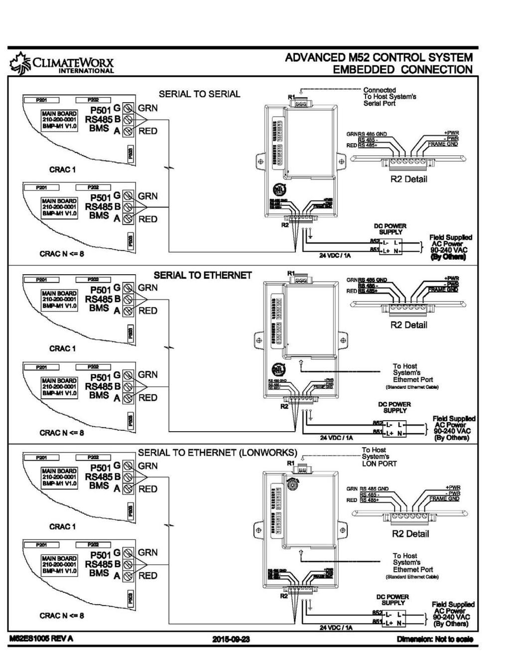
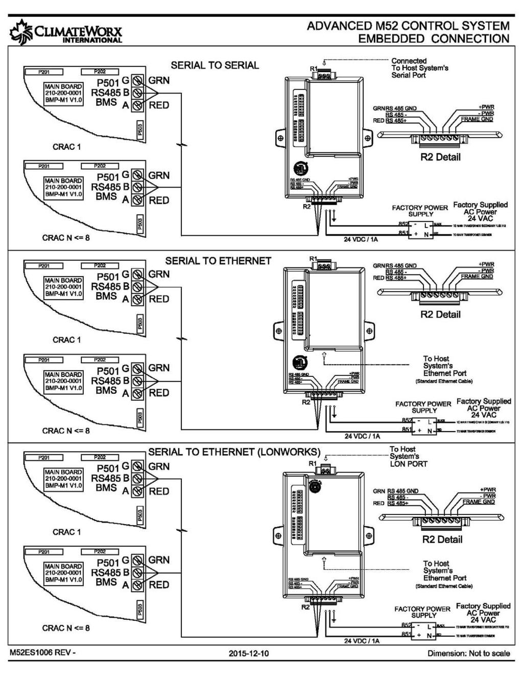
33 Appendix B: Electrical Schematic Drawings Drawing Title Electrical Schematic with standard thermostat Electric Schematic Packaged Air-Cooled General, Electric Schematic Air-Cooled Condensing Unit General, Electric Schematic Air-Cooled Condenser General, Electric Schematic Water/ Glycol-Cooled General, Electric Schematic Chilled Water General, Electric Schematic Dual Cooling Air General, Electric Schematic Dual Cooling Water or Glycol General, Electric Schematic Free Cooling General, Electric Schematic Field Wiring Standby Start/ Standby Enable, For automatic change over Electric Schematic Co-Work I2C Interconnection Link Electric Schematic RS485 ModBus RTU Connection, Serial Communication Link Electric Schematic Embedded Connection, Serial to Serial or Ethernet Communication Link remote power Electric Schematic Embedded Connection, Serial to Serial or Ethernet Communication Link factory power Drawing No. S11EDN105 ES9005 ES9020 ES9030 ES9065 ES9050 ES9030 ES9040 ES9070 M52ES05 M52ES1003 M52ES1004 M52ES1005 M52ES
34 34
35 35
36 36
37 37
38 38
39 39
40 40
41 41
42 42
43 43
44 44
45 45
46 46
47 47
48 Appendix C: Piping Schematic Drawings Drawing Title Drawing No. Page No. SERIES 11- Air Cooled Unit with Condenser S11DS SERIES 11- Air Cooled Unit with Condensing unit S11DS (w/ Head Pressure Control) SERIES 11- Water Cooled Unit (Self contained) S11DS SERIES 11- Water Cooled Unit with Condensing Unit S11DS SERIES 11- Glycol Cooled Unit (Self contained) S11DS SERIES 11- Glycol Cooled Unit with Condensing Unit S11DS SERIES 11- Chilled Water Unit S11DS SERIES 11- Dual Cooled CW + CW Unit S11DS SERIES 11- Dual Cooled CW + DX WC Unit S11DS SERIES 11- Dual Cooled CW + DX GC Unit S11DS SERIES 11- Dual Cooled CW + DX Air Cooled Unit S11DS SERIES 11- Free Cooling Unit S11DS
49 49
50 50
51 51
52 52
53 53
54 54
55 55
56 56
57 57
58 58
59 59
60 60
61 61
Series 11, Ceiling Units
 MISSION CRITICAL Air Conditioning Systems Series 11, Ceiling Units Installation Manual ClimateWorx International Inc. 14 Chelsea Lane, Brampton, Ontario, Canada L6T 3Y4 Table of Contents Table of Contents...
Series 6, Vertical Floor-Mount Units
 MISSION CRITICAL Air Conditioning Systems Series 6, Vertical Floor-Mount Units Installation Manual ClimateWorx International Inc. 14 Chelsea Lane, Brampton, Ontario, Canada L6T 3Y4 2 Table of Contents
Series 6, Vertical Floor-Mount Units
 MISSION CRITICAL Air Conditioning Systems Series 6, Vertical Floor-Mount Units Installation Manual ClimateWorx International Inc. 14 Chelsea Lane, Brampton, Ontario, Canada L6T 3Y4 2 Table of Contents
12 In Row. Installation Manual. MISSION CRITICAL Air Conditioning Systems. ClimateWorx International Inc.
 MISSION CRITICAL Air Conditioning Systems 12 In Row Installation Manual ClimateWorx International Inc. 14 Chelsea Lane, Brampton, Ontario, Canada L6T 3Y4 2 Table of Contents Table of Contents... 3 Site
P-Series, Vertical Floor-Mount Units
 MISSION CRITICAL Air Conditioning Systems P-Series, Vertical Floor-Mount Units Installation Manual ClimateWorx International Inc. 14 Chelsea Lane, Brampton, Ontario, Canada L6T 3Y4 - 2 - SP-IM2018 Table
Service Step by Step Trouble-Shooting Check-List
 WARNING: Only Data Aire trained technician or experience technicians should be working on Data Aire Equipment. Protect yourself at all times and work safe. Date: Dates at the job site: From: to Job#: Serial#:
Condensing Unit Installation and Operating Instructions
 Bulletin WCU_O&I 01 June 2003 Condensing Unit Installation and Operating Instructions WCU Air Cooled Condensing Unit Table of Contents Section 1. Section 2. Section 3. Section 4. Section 5. Section 6.
Condensing Unit Installation and Operating Instructions
 Bulletin ACU_O&I 02 August 2016 Condensing Unit Installation and Operating Instructions ACU Air Cooled Condensers Table of Contents Section 1. General Information... 2 Section 2. Refrigeration Piping...
Series 9. Commissioning Checklist. MISSION CRITICAL Air Conditioning Systems. ClimateWorx International Inc.
 MISSION CRITICAL Air Conditioning Systems Series 9 Commissioning Checklist S9-CL2017.doc ClimateWorx International Inc. 14 Chelsea Lane, Brampton, Ontario, Canada L6T 3Y4 2 S9-CL2017.doc Commissioning
CS/CD/CP AIR COOLED CONDENSING UNITS (P/N E207120C R2)
") CS*/CD*/CP* Series Air Cooled Condensing Units Operating and Installation Manual CS/CD/CP AIR COOLED CONDENSING UNITS (P/N E207120C R2) TABLE OF CONTENTS I. Receipt of Equipment 2 II. Piping...4 III. System
CS*/CD*/CP* Series Air Cooled Condensing Units Operating and Installation Manual CS/CD/CP AIR COOLED CONDENSING UNITS (P/N E207120C R2) TABLE OF CONTENTS I. Receipt of Equipment 2 II. Piping...4 III. System
TABLE OF CONTENTS. NOTE: Read the entire instruction manual before starting the installation. TROUBLESHOOTING... 13
 R 410A Duct Free Split System Air Conditioner and Heat Pump Product Family: DFS4(A/H) System, DFC4(A/H)3 Outdoor, DFF4(A/H)H Indoor NOTE: Read the entire instruction manual before starting the installation.
APPLICATION DATA SHEET
 APPLICATION DATA SHEET General Piping Recommendations and Refrigerant Line Length for Split-System Air Conditioners and Heat Pumps GENERAL GUIDELINES This Split-System (Air Conditioning Condensing/Heat
Air Cooled Condenser Installation and Operating Instructions
 Bulletin CAC_O&I 02 August 2016 Air Cooled Condenser Installation and Operating Instructions CAC Air Cooled Condensers Table of Contents Section 1. General Information... 2 Section 2. Refrigeration Piping...
WineZone Ceiling Mount Ductless Split 15
 WineZone Ceiling Mount Ductless Split 15 Requires an HVAC technician to install and charge with R-22 refrigerant. Easy to install. Unit plugs into wall outlet. Industrial grade unit for longer life. Indoor
AIR CONDITIONING. Carrier Corporation 2002 Cat. No
 AIR CONDITIONING Carrier Corporation 2002 Cat. No. 020-016 1. This refresher course covers topics contained in the AIR CONDITIONING specialty section of the North American Technician Excellence (NATE)
WMHP Series R410a Heat Pump INSTALLATION INSTRUCTIONS
 WMHP Series R410a Heat Pump INSTALLATION INSTRUCTIONS **WARNING TO INSTALLER, SERVICE PERSONNEL AND OWNER** Altering the product or replacing parts with non authorized factory parts voids all warranty
Installation, Operation, and Maintenance Information
 Installation, Operation, and Maintenance Information Air Cooled Condensers 8-2016 Rev 0 Table of Contents General Safety Information 2 Inspection 2 Installation 2 6 Rigging and Assembly 2 Unit Location
Operation & Maintenance Manual
 Operation & Maintenance Manual VUD, VUF, VDF & HCD Series Unit Ventilator IMPORTANT: Read and save this manual for future reference. This manual is to be left with the equipment owner 2006 TEMSPEC INCORPORATED
Installation Instructions
 8GXM / 0GXM Multi---Split High---Wall Duct Free Split System 8GXM --- Size 18k, k, and 0k 0GXM --- Size 9k, 1k, and 18k Installation Instructions NOTE: Read the entire instruction manual before starting
OPERATING INSTRUCTIONS
 OPERATING INSTRUCTIONS - SPLIT DUCTED SYSTEMS CONGRATULATIONS on your purchase of an ActronAir air conditioning system. This energy efficient unit has been precision designed, manufactured from high quality
TECHNICAL GUIDE DESCRIPTION SPLIT-SYSTEM AIR-COOLED CONDENSING UNITS. HA300, HB360, HB480 & HB thru 50 NOMINAL TONS (50 Hz)
") DESCRIPTION These units are completely assembled, piped and wired at the factory to provide one-piece shipment and rigging. Each unit is pressurized with a holding charge of refrigerant-22 for storage
DESCRIPTION These units are completely assembled, piped and wired at the factory to provide one-piece shipment and rigging. Each unit is pressurized with a holding charge of refrigerant-22 for storage
Installation Instructions
 PREFERREDT SERIES AIR CONDITIONER WITH PURONR REFRIGERANT 1-1/2 TO 5 NOMINAL TONS Installation Instructions Fig. 1 --- 538A NOTE: Read the entire instruction manual before starting the installation. TABLE
TECHNICAL GUIDE DESCRIPTION SPLIT-SYSTEM AIR-COOLED CONDENSING UNITS MODELS: HF-07 FEATURES B-0703
 TECHNICAL GUIDE SPLIT-SYSTEM AIR-COOLED CONDENSING UNITS MODELS: HF-07 DESCRIPTION These Sunline 2000 units are completely assembled, piped and wired at the factory to provide one-piece shipment and rigging.
Single Package Vertical Unit (SPVU) Installation, Operation and Maintenance Manual Effective August 2018
 Installation, Operation and Maintenance Manual Effective August 2018") VertiCool CLASSIC Single Package Vertical Unit (SPVU) Installation, Operation and Maintenance Manual Effective August 2018 Air-Cooled, Water-Cooled, Chilled Water and Water Source Heat Pump Contents Installation,
VertiCool CLASSIC Single Package Vertical Unit (SPVU) Installation, Operation and Maintenance Manual Effective August 2018 Air-Cooled, Water-Cooled, Chilled Water and Water Source Heat Pump Contents Installation,
YCIV Hz & Hz
 YCIV 0590-1500 50Hz & 0157-0397 60Hz Start-up Checklist SERVICE POLICY & PROCEDURES Supersedes: Nothing Form 201.23-CL1 (309) Commissioning PREPARATION Commissioning of this unit should only be carried
Some of these procedures need to be performed to conform to requirements of the Clean Air Act.
 Leak Detection, Recovery, Evacuation and Charging Four basic service procedures used to repair and maintain a mechanical refrigeration system are leak detection, evacuation, recovery, and refrigerant charging.
Table of Contents. Service Procedures. Service Procedures. Measuring Superheat (4) Measuring Subcooling (5) Airflow Calculation (6-8)
 Measuring Subcooling (5) Airflow Calculation (6-8)") Table of Contents Refrigeration Cycle Service Procedures Measuring Superheat (4) Measuring Subcooling (5) Airflow Calculation (6-8) Solving Problems Identifying Low System Charge (9-11) Identifying High
Table of Contents Refrigeration Cycle Service Procedures Measuring Superheat (4) Measuring Subcooling (5) Airflow Calculation (6-8) Solving Problems Identifying Low System Charge (9-11) Identifying High
MODEL YVAA EQUIPMENT PRE-STARTUP AND STARTUP CHECKLIST CUSTOMER: LOCATION: ADDRESS: CUSTOMER ORDER NO: PHONE: JCI CONTRACT NO: JOB NAME:
 Supersedes: 201.28-CL2 (817) Form 201.28-CL2 (1017) MODEL YVAA EQUIPMENT PRE-STARTUP AND STARTUP CHECKLIST CUSTOMER: LOCATION: ADDRESS: PHONE: JOB NAME: CUSTOMER ORDER NO: JCI CONTRACT NO: CHILLER MODEL
Installation and Programming Instructions for. Deluxe Programmable Thermostats
 Installation and Programming Instructions for Deluxe Programmable Thermostats TABLE OF CONTENTS INTRODUCTION...4 STANDARD FEATURES...4-6 THERMOSTAT LOCATION...7 REMOVING THE THERMOSTAT FROM THE SUBBASE...8
HEAT COOL. Meets Commercial California Title 24
 Digital Thermostat commercial THERMOSTAT T2900 7-DAY MABLE up to 3-heat & 2-cool HEAT COOL HEAT PUMP Control up to 3 Heat & 2 Cool Stages 3 Configurable Outputs Adjustable 2nd & 3rd Stage Timers & Deadbands
INSTALLATION INSTRUCTIONS HOT GAS BYPASS SYSTEM DESIGN MANUAL
 INSTALLATION INSTRUCTIONS HOT GAS BYPASS SYSTEM DESIGN MANUAL MODELS: WA242H WA36H NOTE: Electrical data presented in this manualsupersedes any other data for the above listed models. Bard Manufacturing
Single Package Vertical Unit (SPVU) Installation, Operation and Maintenance Manual Effective September 2017
 Installation, Operation and Maintenance Manual Effective September 2017") VertiCool CLASSIC Single Package Vertical Unit (SPVU) Installation, Operation and Maintenance Manual Effective September 2017 Air-Cooled, Water-Cooled, Chilled Water and Water Source Heat Pump Important
VertiCool CLASSIC Single Package Vertical Unit (SPVU) Installation, Operation and Maintenance Manual Effective September 2017 Air-Cooled, Water-Cooled, Chilled Water and Water Source Heat Pump Important
EMERSON BLUE Wireless Comfor t Inter face 1F98EZ-1621 HOMEOWNER USER GUIDE
 EMERSON BLUE Wireless Comfor t Inter face 1F98EZ-1621 HOMEOWNER USER GUIDE Emerson Blue Wireless Comfort Interface - Homeowner User Guide Message to Homeowners Congratulations on choosing the Emerson Blue
KITS COMMON TO HEATING AND COOLING EQUIPMENT 504,652M 03/04. Supersedes 503,249M
 2004 Lennox Industries Inc. Dallas, Texas KITS COMMON TO HEATING AND COOLING EQUIPMENT 504,652M 03/04 Supersedes 503,249M Litho U.S.A. COMPRESSOR REPLACEMENT KIT INSTALLATION INSTRUCTIONS FOR COMPRESSOR
EQUIPMENT PRE-STARTUP AND STARTUP CHECKLIST TEL NO: ORDER NO: CONTRACT NO:
 Supersedes: (316) Form QTC4-CL2 (617) MODEL QTC4 EQUIPMENT PRE-STARTUP AND STARTUP CHECKLIST CUSTOMER: ADDRESS: PHONE: JOB NAME: LOCATION: CUSTOMER ORDER NO: TEL NO: ORDER NO: CONTRACT NO: CHILLER MODEL
OPERATING & MAINTENANCE MANUAL HORIZONTAL WATER SOURCE HEAT PUMP. World class comfort.
 OPERATING & MAINTENANCE MANUAL HORIZONTAL WATER SOURCE HEAT PUMP World class comfort. welcome Congratulations on your selection of Ice Air Water Source Heat Pumps (WSHPs) for your comfort conditioning
CAREFULLY READ THESE INSTRUCTIONS BEFORE USING SAFETY PRECAUTIONS USE OF EXTENSION CORDS
 Owner s Manual CR2500ACH CR5000ACH Portable Heating and Air Conditioning Unit Version 02 Table of Contents 1. SAFETY INSTRUCTIONS... 1-1 CAREFULLY READ THESE INSTRUCTIONS BEFORE USING... 1-1 SAFETY PRECAUTIONS...
NOTE: Special care should be given to those areas where these symbols appear.
 CONGRATULATIONS ON THE SELECTION OF A DATA AIRE PRECISION ENVIRONMENTAL CONTROL SYSTEM. PROPER INSTALLATION, OPERATION AND MAINTENANCE OF THIS EQUIPMENT WILL ENSURE YEARS OF OPTIMAL PERFORMANCE. There
Mission Critical. Series 6, 8 & 9. vertical floor mount Ton Units. Air Conditioning Systems
 Mission Critical Air Conditioning Systems vertical floor mount Series 6, 8 & 9 2-30 Ton Units Single Circuit for Superior Economy and Dual Circuit for Ultimate Protection Series 6 2-5 tons Compact Footprint
SPX SERIES PACKAGED AIR CONDITIONING/HEAT PUMP UNITS INSTALLATION, OPERATION AND MAINTENANCE INSTRUCTIONS
 SPX SERIES PACKAGED AIR CONDITIONING/HEAT PUMP UNITS INSTALLATION, OPERATION AND MAINTENANCE INSTRUCTIONS **WARNING TO INSTALLER, SERVICE PERSONNEL AND OWNER** Altering the product or replacing parts with
Contour TM Screw Compressors
 Contour TM Screw Compressors Semi-Hermetic Compact Operating Instruction SCH1 High Temp Compressors Form No. 99-77 1. Introduction This series of semi-hermetic compact screw compressors is designed for
OWNER S MANUAL Venstar Inc. 08/07
 Digital Thermostat commercial SCHOOL THERMOSTAT T2900SCH MABLE up to 3-heat & 2-cool HEAT COOL HEAT PUMP Energy Saving Operation Morning Warm-up Period Programmable Override Unoccupied until button press
INSTALLATION INSTRUCTIONS
 INSTALLATION INSTRUCTIONS T CLASS TSA Series 6 to 20 Ton AIR CONDITIONERS 6 20 TONS 506147 01 06/11 Supersedes 3/11 Litho U.S.A. RETAIN THESE INSTRUCTIONS FOR FUTURE REFERENCE IMPORTANT The Clean Air Act
AMERICAN EQUIPMENT SYSTEMS A Division Of Trevor-Martin Corporation th Terrace North Clearwater, Florida 33762
 AMERICAN EQUIPMENT SYSTEMS A Division Of Trevor-Martin Corporation 4151 112 th Terrace North Clearwater, Florida 33762 COMMERCIAL REFRIGERANT DESUPERHEATER WASTE HEAT RECOVERY INSTALLATION/OPERATION/MAINTENANCE
5) Do not start or stop the unit by inserting or pulling out the power plug.
 Do not start or stop the unit by inserting or pulling out the power plug.") 3058080 V170306 PURCHASE INFORMATION Thank you for choosing a Soleus Air Portable Air Conditioner. This Owner s Manual will provide you with valuable information necessary for the proper care and maintenance
3058080 V170306 PURCHASE INFORMATION Thank you for choosing a Soleus Air Portable Air Conditioner. This Owner s Manual will provide you with valuable information necessary for the proper care and maintenance
Installation Instructions
 24AHA4 Performance Series Air Conditioner with Puron Refrigerant 1-1/2 to 5 Nominal Tons Installation Instructions Fig. 1-24AHA4 A07532 SAFETY CONSIDERATIONS Improper installation, adjustment, alteration,
Ocean Breeze Split System. General Installation Manual. Ocean Breeze 2951 SE Dominica Terrace Stuart, Florida Tel:
 Ocean Breeze Split System General Installation Manual Ocean Breeze 2951 SE Dominica Terrace Stuart, Florida 34997 Tel: 772 220 0038 Warning: The Air Conditioning Unit is a pressurized system; potential
June 2001 / BULLETIN Way Valves. The right solenoid valve for any job.
 June 01 / BULLETIN - 3-Way Valves The right solenoid valve for any job. Page 2 / Bulletin - Advantages Sporlan 3-Way Valves 3-Way Pilot eliminates costly high- to low-side leaks. "B" reduces total installed
INSTALLATION INSTRUCTIONS
 INSTALLATION INSTRUCTIONS SPLIT AIR CONDITIONER OUTDOOR SECTION Models: HAC481-B HAC602-B For Use With: Matching Indoor Blower Coil Units and Matching Add On Coil Units Only Bard Manufacturing Company,
TECHNICAL MANUAL CX(E) SPLIT SYSTEMS. Tel: Fax:
 SPLIT SYSTEMS. Tel: Fax:") TECHNICAL MANUAL CX(E) SPLIT SYSTEMS CONTENTS INDEX PART NUMBERS, OPTIONS, UNIT COMBINATIONS, DIMENSIONS & WEIGHTS 3 PERFORMANCE DATA & AIR FLOW 4 SOUND POWER AND SOUND PRESSURE LEVELS 5 ELECTRICAL DATA
TECHNICAL MANUAL CX(E) SPLIT SYSTEMS CONTENTS INDEX PART NUMBERS, OPTIONS, UNIT COMBINATIONS, DIMENSIONS & WEIGHTS 3 PERFORMANCE DATA & AIR FLOW 4 SOUND POWER AND SOUND PRESSURE LEVELS 5 ELECTRICAL DATA
CONDENSING UNITS SPLIT-SYSTEM COOLING 6-1/3 TONS INSTALLATION INSTRUCTION MODELS H*DB076 NOMENCLATURE GENERAL LIMITATIONS INSPECTION REFERENCE
 INSTALLATION INSTRUCTION CONDENSING UNITS SPLIT-SYSTEM COOLING 6-1/3 TONS Supersedes: Nothing 550.38-N6Y (1095) MODELS H*DB076 035-13578 WARNINGS are given to alert the installer that severe personal injury,
DLCLRA. INSTALLATION INSTRUCTIONS Outdoor Unit Single Zone Ductless System Sizes 36 to 58 TABLE OF CONTENTS
 DLCLRA INSTALLATION INSTRUCTIONS Outdoor Unit Single Zone Ductless System Sizes 36 to 58 Fig. 1 - Size 36 TABLE OF CONTENTS PAGE SAFETY CONSIDERATIONS... 2 PARTS LIST... 3 SYSTEM REQUIREMENTS... 4 WIRING...
Instruction Guide: Thermostat Operation
 Instruction Guide: Elite Communicating Thermostats TPCM32U03*/TPCM32U04* (*GSR, GSM, TRN, AST) INSTRUCTION GUIDE: ELITE COMMUNICATING THERMOSTAT Thermostat Operation NOTE: These communicating thermostats
Daikin Direct Expansion (DX) Cooling Coils
 Cooling Coils") Installation and Maintenance Manual IM 902 Daikin Direct Expansion (DX) Cooling Coils Group: Applied Air Part Number: IM 902 Date: February 2008 Types EN, EF, ER, EJ, EK 2008 Daikin Applied Contents Introduction...
Installation and Maintenance Manual IM 902 Daikin Direct Expansion (DX) Cooling Coils Group: Applied Air Part Number: IM 902 Date: February 2008 Types EN, EF, ER, EJ, EK 2008 Daikin Applied Contents Introduction...
CAREFULLY READ THESE INSTRUCTIONS BEFORE USING SAFETY PRECAUTIONS USE OF EXTENSION CORDS
 Owner s Manual CR2500ACH CR5000ACH Portable Heating and Air Conditioning Unit Version 01 Table of Contents 1. SAFETY INSTRUCTIONS... 1-1 CAREFULLY READ THESE INSTRUCTIONS BEFORE USING... 1-1 SAFETY PRECAUTIONS...
Warm Case Troubleshooting Guide 9/18/2014
 Introduction Warm cases can be caused by various problems which require thorough troubleshooting. Begin the investigation with questions to store personnel asking for information such as when the last
INSTALLATION AND OPERATING INSTRUCTIONS
 INSTALLATION AND OPERATING INSTRUCTIONS HIGH-EFFICIENCY CONDENSING UNITS RAWD- 6 1 2 & 7 1 2 TON RAWE - 6 1 2 & 7 1 2 TON! RECOGNIZE THIS SYMBOL AS AN INDICATION OF IMPORTANT SAFETY INFORMATION!! WARNING
Read and save these instructions
 Split Water-Cooled Central-Ducted Cooling System Operation Care Installation Manual CT14TSHWC CT13TSHWC CT12TSHWC CT34TSHWC CT1TSHWC www.apexwinecellars.com 17631 S Susana Road Rancho Dominguez, CA 90221
PARALLEL RACK SYSTEM INSTALLATION & OPERATIONS MANUAL With Master Rack Compressor Sequencer
 PARALLEL RACK SYSTEM INSTALLATION & OPERATIONS MANUAL With Master Rack Compressor Sequencer 5/16 Rev. A 57-02509 2 Contents INTRODUCTION... 4 WARNING LABELS AND SAFETY INSTRUCTIONS... 5 PS SERIES PARALLEL
INSTALLATION MANUAL COMMERCIAL SPLIT SYSTEM COOLING UNITS 4 PIPE SYSTEMS 15 THROUGH 20 NOMINAL TON HB B-0804
 INSTALLATION MANUAL COMMERCIAL SPLIT SYSTEM COOLING UNITS 4 PIPE SYSTEMS 15 THROUGH 20 NOMINAL TON CONTENTS GENERAL................................. 3 REFERENCE............................... 3 INSPECTION...............................
WKS 2200 SERIES (USA only) --INSTALLATION INSTRUCTIONS--
 --INSTALLATION INSTRUCTIONS--") 8610 Production Avenue San Diego, California 92121 (858) 566-7465 Fax (858) 566-1943 WWW.BREEZAIRE.COM WKS 2200 SERIES (USA only) --INSTALLATION INSTRUCTIONS-- Thank you for choosing a BREEZAIRE cooling
8610 Production Avenue San Diego, California 92121 (858) 566-7465 Fax (858) 566-1943 WWW.BREEZAIRE.COM WKS 2200 SERIES (USA only) --INSTALLATION INSTRUCTIONS-- Thank you for choosing a BREEZAIRE cooling
VariCool VAV Engineering Guide
 Engineering Guide Effective September 2017 Water-Cooled and Chilled Water, Variable Air Volume Contents Product Features... 3 UNIT FEATURES... 3 Product Features... 4 Marvel Plus Microprocessor Control
Series 6. Guide Specification 60 Hz. MISSION CRITICAL Air Conditioning Systems. ClimateWorx International Inc.
 MISSION CRITICAL Air Conditioning Systems Series 6 Guide Specification 60 Hz S6-GS-602017.doc ClimateWorx International Inc. 14 Chelsea Lane, Brampton, Ontario, Canada L6T 3Y4 Series 6 Guide Specification-60
Series 8. Guide Specification 60 Hz. MISSION CRITICAL Air Conditioning Systems. ClimateWorx International Inc.
 MISSION CRITICAL Air Conditioning Systems Series 8 Guide Specification 60 Hz S8-GS-602017.doc 2014 ClimateWorx International Inc. 14 Chelsea Lane, Brampton, Ontario, Canada L6T 3Y4 Series 8 Guide Specification-60
C13-Series Engineering Guide
 Engineering Guide Effective January 2018 Horizontal Air-Cooled, Water-Cooled, Chilled Water and Heat Pump Contents Product Features............................... 3 Product Options................................
Split Refrigeration Systems
 Control the Elements Split Refrigeration Systems Owner s Manual V10.14 C O N G R A T U L A T I O N S! Thank you for purchasing a new CellarPro cooling system. Please take a minute to read through this
Installation Instructions
 38MHR Outdoor Unit Single Zone Ductless System Sizes 09 to 24 Installation Instructions NOTE: Read the entire instruction manual before starting the installation. NOTE: Images are for illustration purposes
Hood Depot Internatioonal, Inc., Phone S. Powerline Road, Deerfield Beach, FL
 The Kitchen Cool by Hood Depot is a conditioned make up air unit design with flexibility, form and function kept in mind. Our unit offers a variety of configurations that allow the customer to customize
Air-Cooled Condenser. Installation Instructions. Revision Date: 12/21/98
 Air-Cooled Condenser Installation Instructions Revision Date: 12/21/98 ! WARNING! These installation guidelines must be followed to obtain reliable operation from air-cooled ice machines. If these guidelines
RCM Refrigerant Module
 Small Duct High Velocity Heating, Cooling and Home Comfort Systems RCM Refrigerant Module Installation Manual Manufactured By Module-RCM-Refrigerant-Module-Installation-0666 Refrigerant Modules (RCM) Fig.
INSTALLER'S GUIDE. ALL phases of this installation must comply with NATIONAL, STATE AND LOCAL CODES
 11-AC11D2-5 INSTALLER'S GUIDE ALL phases of this installation must comply with NATIONAL, STATE AND LOCAL CODES Models: Condensing Units 2A7A5024-048, 2A7A4018-060, 2A7A2018-060 & 2A7A1018-060 IMPORTANT
MISSION CRITICAL Air Conditioning Systems. Maintenance Guide. ClimateWorx International Inc. 14 Chelsea Lane, Brampton, Ontario, Canada L6T 3Y4
 MISSION CRITICAL Air Conditioning Systems Maintenance Guide ClimateWorx International Inc. 14 Chelsea Lane, Brampton, Ontario, Canada L6T 3Y4 Vertical Floor /Wall /Ceiling Mount - Maintenance Manual 2
Mission Critical Air Conditioning Systems
 Mission Critical Air Conditioning Systems wall & ceiling mount Series 7 & 11 1-5 Ton Units Single Circuit Units Designed for Superior Space Utilization Series 7 1.5-2.5 tons Compact wall mounted split
Portable Air Conditioner with Heat Pump Technology Operating Instructions. Model No.: HCB-P13HP-D. Reference No.: BPD13HP V140217
 Portable Air Conditioner with Heat Pump Technology Operating Instructions 3092402 Model No.: HCB-P13HP-D Reference No.: BPD13HP V140217 Thank you for choosing a Soleus Air Portable Air Conditioner with
OPERATION MANUAL CM25. Unit Serial Number Range: 1009XXXXC25 to Present (From October 2009 to Present)
") OPERATION MANUAL CM25 Unit Serial Number Range: 1009XXXXC25 to Present (From October 2009 to Present) READ THIS MANUAL CAREFULLY FOR INSTRUCTIONS ON CORRECT INSTALLATION AND USAGE, AND READ ALL SAFEGUARDS.
OPERATION MANUAL CM25 Unit Serial Number Range: 1009XXXXC25 to Present (From October 2009 to Present) READ THIS MANUAL CAREFULLY FOR INSTRUCTIONS ON CORRECT INSTALLATION AND USAGE, AND READ ALL SAFEGUARDS.
Installation Manual BCS2000/3000
 Installation Manual BCS2000/3000 Supplies Needed for Installation 1. 3/8 and 5/8 copper tubing. 2. 1/4 copper water supply 3. 1/4 condensate vinyl drain tube/tube clamps 4. Provide 120v 15A circuit for
EarthLinked SW Series Compressor Unit R-410A Quik-Start Instructions
 EarthLinked SW Series Compressor Unit R-410A Quik-Start Instructions CONTENTS PAGE Pre-Installation 3 Placement & Mechanical Information 4 System Application Options 10 Antifreeze Protection 14 Electrical
Residential Piping and Long Line Guideline
 AC / HP R-410A Refrigerant Systems Single-Stage, Two-Stage and Variable Speed Models Residential Piping and Long Line Guideline TABLE OF CONTENTS Safety Considerations... 2 Definitions... 2 Introduction...
R Series Cooling Modules
 TM Small Duct High Velocity Heating, Cooling and Indoor Air Quality Systems R Series Cooling Modules Models RCM-50 RCM-70 RM-100 Manufactured By Module-RCM/RM-Series-Installation-Manual-120113 Refrigerant
Instructors: Contact information. Don Reynolds Doug McGee Factory Tech Support
 Contact information Instructors: Don Reynolds 616-560-9903 Doug McGee 517-294-3932 Factory Tech Support 888-593-9988 Product Improvements for 2017 Todays Objectives Job Site Information Sheets Low Ambient
Installation Instructions
 Installation Instructions B-Series VT40, VT60, VT100 Important Safety Notice. This information is intended for use by individuals possessing adequate backgrounds of electrical, refrigeration and mechanical
R Series Cooling Modules
 R Series Cooling Modules Models RCM/RPM 50 RCM 70 RM 100 RM 140 Manufactured By Energy Saving Products Ltd. Standard ESP 105.03 Refrigerant Modules (RCM/RM) Fig. 02 - Mounting brackets The cooling coil
PDF Created with deskpdf PDF Writer - Trial ::
 Instruction Manual Index Introduction Uncrating and Checking for Damage Locating Your Unit Installation Fill Tank Process Connections Pre Startup Startup Sequence Trouble Shooting Chart Operating Lights
User s Information and Installation Instructions
 Outdoor Air Conditioner User s Information and Installation Instructions 10 SEER Standard Efficiency Split System These units have been designed and tested for capacity and efficiency in accordance with
High Profile Evaporator
 PRODUCT DATA & INSTALLATION Bulletin K30-KHPA-PDI-5 Part # 1081585 PRODUCT SUPPORT web: k-rp.com/khp email: evaps@k-rp.com call: 1-844-893-3222 x520 scan: High Profile Evaporator High & Medium Temperature
Mortex INSTALLATION INSTRUCTIONS AIR CONDITIONING & HEAT PUMP INDOOR COILS
 Mortex INSTALLATION INSTRUCTIONS AIR CONDITIONING & HEAT PUMP INDOOR COILS INTRODUCTION Please note that HUD Manufactured Home Construction and Safety Standard Section 3280.714, paragraph (a) and subparagraph
HEAT HEAT HEAT COOL COOL PUMP OWNER S MANUAL 7-DAY TOTALINE
 OWNER S MANUAL COMMERCIAL THERMOSTAT P/N P374-2800 I 2 : 0 0 Su AUTO Pm 74 COOL 7 2 HEAT T O T A L I N E HEAT COOL 7-DAY HEAT PUMP PROGRAMMABLE DIGITAL THERMOSTAT 3 Configurable Outputs Control up to 2
I N STALLATIO N. VRC Series IOM-M Part Number
 M ECHANICAL I N STALLATIO N O PERATION & MA I NTENANCE VRC Series IOM-M2-0916 Part Number 478603 Table of Contents Safety... 3 Special Design Requests... 3 Model Number Guide... 3 Clearances... 4 Lifting
CR13000-PAC OWNER S MANUAL. Portable Air Conditioner. PORTABLE AIR CONDITIONER with HEAT PUMP. Operating and Servicing Instructions
 OWNER S MANUAL Operating and Servicing Instructions CR13000-PAC PORTABLE AIR CONDITIONER with HEAT PUMP Portable Air Conditioner Questions or concerns? For assistance, please call Customer Service ClimateRight
Horizontal/Side Discharge Condensing Units
 INSTALLATION, OPERATION & MAINTENANCE MANUAL Horizontal/Side Discharge Condensing Units Models CMA12SD-0 CMA18SD-1 CMA24SD-1 CMA30SD-1 CMA36SD-1 CMA48SD-1 517.787.2100 www.marsdelivers.com Horizontal/Side
SPLIT-SYSTEM EVAPORATOR BLOWER DESCRIPTION FEATURES L4EU NOMINAL TONS
 036-21096-001 (0101) SPLIT-SYSTEM EVAPORATOR BLOWER L4EU240 20 NOMINAL TONS DESCRIPTION This 20 ton evaporator blower is designed with two distinct modules to provide maximum application flexibility. The
14,000 BTU Portable Air Conditioner 14,200 BTU Heat Pump Model Number: LX-140 Operating Instructions. Model No. LX Soleus Air International
 14,000 BTU Portable Air Conditioner 14,200 BTU Heat Pump Model Number: LX-140 Operating Instructions 3092402 Model No. LX-140 2012 Soleus Air International Thank you for choosing a Soleus Air LX-140 Portable
APPLICATION GUIDELINES FOR COPELAND COMPLIANT SCROLL COMPRESSORS (ZR*1 Models)
") 4-1280 Application Engineering Bulletin AE-1280R4 Revised April, 1995 APPLICATION GUIDELINES FOR COPELAND COMPLIANT SCROLL COMPRESSORS (ZR*1 Models) Introduction The Compliant Scroll Compressor has been
4-1280 Application Engineering Bulletin AE-1280R4 Revised April, 1995 APPLICATION GUIDELINES FOR COPELAND COMPLIANT SCROLL COMPRESSORS (ZR*1 Models) Introduction The Compliant Scroll Compressor has been
MASS. MARITIME ACADEMY
 MASS. MARITIME ACADEMY REFRIGERATION LAB OUTLINE Rev.3 Fall 2015 Table of Content Page Lab #1: Introduction to refrigeration system components, tools and procedures 1 Lab #2: Familiarization, operation,
Chapter-8 Capacity Control of Refrigeration Systems
 Chapter-8 Capacity Control of Refrigeration Systems Chapter-8 Capacity Control of Refrigeration Systems ၈.၁ Compressor Control Chiller Control and Chilled Water Plant Control Refrigeration system control
Portable Air Conditioner 6,000 BTU 8,000 BTU 10,000 BTU
 Portable Air Conditioner 6,000 BTU 8,000 BTU 10,000 BTU OPERATING INSTRUCTIONS PCR-06-01 PCR-08-01 PCR-10-01 3058080 V170223 PURCHASE INFORMATION Thank you for choosing a Chigo Portable Air Conditioner.
Assessment Schedule - TS8
 The Assessor shall determine the business s commitment and support to good and safe working practices; also that it has a positive culture in all aspects of its work. In particular, the assessor shall
Split Floor-Mounted Cooling System Operation Care Installation Manual
 Split Floor-Mounted Cooling System Operation Care Installation Manual CT14TSA CT13TSA CT12TSA CT34TSA CT1TSA CT14TSA-LA CT13TSA-LA CT12TSA-LA CT34TSA-LA CT1TSA-LA www.apexwinecellars.com Apex 17631 S Susana
UHIR Series. Horizontal or Vertical Mounting Industrial / Commercial Electric Unit Heater. Owner s Manual
 UHIR Series Horizontal or Vertical Mounting Industrial / Commercial Electric Unit Heater Owner s Manual This manual covers installation, maintenance and repair parts. Read carefully before attempting to
1025, BOUL. MARCEL-LAURIN INSTRUCTION MANUAL FOR WATER COOLED ENVIROCHILL CHILLER. Prepared par Claude Gadoury, P. Eng MTL TECHNOLOGIES INC.
 WYETH-AYERST CANADA INC. 1025, BOUL. MARCEL-LAURIN S T - L A U R E N T, Q U É B E C INSTRUCTION MANUAL FOR WATER COOLED ENVIROCHILL CHILLER MODEL P448800LT--55WC--22C66S Prepared par Claude Gadoury, P.