SPECIFICATION CATALOG. Commercial 3 to 6 Ton. Water Source/Geothermal Heat Pump
|
|
|
- Emmeline McBride
- 6 years ago
- Views:
Transcription


1 SPEIFIATION ATALOG ommercial 3 to 6 Ton Water Source/Geothermal Heat Pump
2
3 Table of ontents Model Nomenclature Electrical Availability AHI Data The Versatec Variable Speed Series Inside the Versatec Variable Speed Series ontrols Application Notes Water Quality Installation Notes Vertical Dimensional Data Horizontal Dimensional Data Hanger Bracket Locations Physical Data Electrical Data Blower Performance Data Selection Example eference alculations Legend and Notes Operating Limits Pressure Drop Performance Data Wiring Schematics Engineering Guide Specifications evision Guide
4 Model Nomenclature UV V 036 T L A N 15 A 16 N A SS 23 * Model Type UV Versatec ecv Variable Speed abinet onfiguration V Vertical H Horizontal ontal Unit apacity (MBTUH) 036, 048, 060, 0, 072 Discharge onfiguration T Top (Vertical) E End (Horizontal) onta S Side (Horizontal) ont eturn Air onfiguration L Left ight Voltage /60/1 0/ /60/3 0/ /60/3 efrigeration Option 0 None 2 HWG Only w/o Pump 6 Hot Gas Bypass Blower Options 1 Variable Speed ed EM Blower Water oil Option opper, Uninsulatednsulated D opper, Insulated N upronickel, Uninsulated P upronickel, Insulated Sound Kit Option A None B Sound Kit Vintage * Factory Use Non-Standard Options SS Standard Drain Pan Option 0 omposite, No Secondary onnection 1 omposite, Secondary onnection 2 Stainless Steel, No Secondary onnection 3 Stainless Steel, Secondary onnection Air oil Option 3 All-Aluminum, Uncoated 4 All-Aluminum, AlumiSeal TM Filter Option A 1" MEV 4 B 2" MEV 13 abinet Option 0 Unpainted abinet, Filter ail 1 Painted abinet, Filter ail 2 Unpainted abinet, 4-Sided Filter ack 3 Painted abinet, 4-Sided Filter ack Electrical Option N None D Disconnect Aurora Advanced ontrol Option A Standard E Aurora TM DD F Aurora TM DD w/lon Water ontrol Option N None Water Flow egulator V Modulating Valve F Flow Meter ev.: Electrical Availability VS EM Voltage Model /60/ /60/3 460/60/3 575/60/3 N/A N/A N/A N/A Legend: NA = Not Available = Voltage available in this size 8/25/2016 4
5 AHI Data VS EM Motors AHI/ASHAE/ISO English (IP) Units Model apacity Modulation Flow ate gpm cfm Water Loop Heat Pump Ground Water Heat Pump Ground Loop Heat Pump ooling EWT 86 F apacity Btuh EE Btuh/W Heating EWT 68 F apacity Btuh OP ooling EWT 59 F apacity Btuh EE Btuh/W Heating EWT 50 F apacity Btuh OP ooling Brine Full Load 77 F Part Load 68 F apacity Btuh EE Btuh/W Heating Brine Full Load 32 F Part Load 41 F apacity Btuh Full , , , , , , Part , , , , , , Full , , , , , , Part , , , , , , Full , , , , , , Part , , , , , , Full , , , , , , Part , , , , , , /25/16 ooling capacities based upon 80.6 F DB, 66.2 F WB entering air temperature Heating capacities based upon 68 F DB, 59 F WB entering air temperature All ratings based upon 208V operation OP All UV Series product is safety listed under UL1995 thru ETL and performance listed with AHI in accordance with standard
6 AHI Data cont. The performance standard AHI/ASHAE/ISO became effective January 1, 2000 and replaces AHI Standards 320, 325, and 330. This new standard has three major categories: Water Loop (comparable to AI 320), Ground Water (AI 325), and Ground Loop (AI 330). Although these standards are similar there are some differences: Unit of Measure: The ooling OP The cooling efficiency is measured in EE (US version measured in Btu/h per Watt. The Metric version is measured in a cooling OP (Watt per Watt) similar to the traditional OP measurement. Water onditions Differences Entering water temperatures have changed to reflect the centigrade temperature scale. For instance the water loop heating test is performed with 68 F (20 ) water rounded down from the old 70 F (21.1 ). Air onditions Differences Entering air temperatures have also changed (rounded down) to reflect the centigrade temperature scale. For instance the cooling tests are performed with 80.6 F (27 ) dry bulb and 66.2 F (19 ) wet bulb entering air instead of the traditional 80 F (26.7 ) DB and 67 F (19.4 ) WB entering air temperatures. 80.6/66.2 data may be converted to 80/67 using the entering air correction table. This represents a significantly lower relative humidity than the old 80/67 of 50% and will result in lower latent capacities. Pump Power orrection alculation Within each model, only one water flow rate is specified for all three groups and pumping Watts are calculated using the following formula. This additional power is added onto the existing power consumption. Pump power correction = (gpm x ) x (Press Drop x 2990) / 300 Where gpm is waterflow in gpm and Press Drop is the pressure drop through the unit heat exchanger at rated water flow in feet of head. Blower Power orrection alculation Blower power is corrected to zero external static pressure using the following equation. The nominal airflow is rated at a specific external static pressure. This effectively reduces the power consumption of the unit and increases cooling capacity but decreases heating capacity. These Watts are significant enough in most cases to increase EE and OPs fairly dramatically over AI 320, 325, and 330 ratings. Blower Power orrection = (cfm x 0.472) x (esp x 249) / 300 Where cfm is airflow in cfm and esp is the external static pressure at rated airflow in inches of water gauge. ISO apacity and Efficiency alculations The following equations illustrate cooling calculations: ISO ooling apacity = ooling apacity (Btu/h) + (Blower Power orrection (Watts) x 3.412) ISO EE Efficiency (W/W) = ISO ooling apacity (Btu/h) x / [Power Input (Watts) - Blower Power orrection (Watts) + Pump Power orrection (Watt)] The following equations illustrate heating calculations: ISO Heating apacity = Heating apacity (Btu/h) - (Blower Power orrection (Watts) x 3.412) ISO OP Efficiency (W/W) = ISO Heating apacity (Btu/h) x / [Power Input (Watts) - Blower Power orrection (Watts) + Pump Power orrection (Watt)] omparison of Test onditions AI 320 ISO/AHI WLHP AI 325 ISO/AHI GWHP AI 330 onversions: Airflow (lps) = cfm x 0.472; Water Flow (lps) = gpm x ; esp (Pascals) = esp (in wg) x 249; Press Drop (Pascals) = Press Drop (ft hd) x 2990 ISO/AHI GLHP ooling Entering Air - DB/WB F 80/ / / / / /66.2 Entering Water - F / Fluid Flow ate * ** ** ** ** ** Heating Entering Air - DB/WB F Entering Water - F / Fluid Flow ate * ** ** ** ** ** Note *: Flow rate is set by 10 F rise in standard cooling test Note **: Flow rate is specified by the manufacturer Part load entering water conditions not shown. WLHP = Water Loop Heat Pump; GWHP = Ground Water Heat Pump; GLHP = Ground Loop Heat Pump 6
.")


 with opeland Gen2 Variable Speed ompressors")


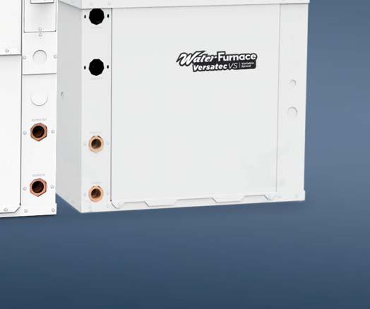
7 The Versatec Variable Speed Series The Versatec Variable Speed represents a significant improvement in the commercial water source heat pump (wshp). The -410A product features high efficiency variable capacity compressors with industry leading standard options in a compact cabinet suitable for both retrofit and new construction applications. The product is also targeted to provide optimum performance and flexibility in both water loop and geothermal applications. The Versatec Variable Speed is a new level of innovation and performance with all new advanced controls mated with variable speed compressor technology. Featuring the highest commercial efficiencies (Over 25 EE and 7.8 OP ISO/AHI WLHP) available in AHI, the Versatec Variable Speed is available in 4 variable speed capacity sizes (3 to 6 ton) with opeland Gen2 Variable Speed ompressors and drives. These units feature high efficiency permanent magnet compressors coupled with high efficiency electronic drives to allow smooth capacity between 25 and 100%. These Versatec Variable Speed units utilize ozone-safe -410A refrigerant to meet the most stringent EPA requirements. Exclusive all aluminum air coils add durability and longer life. Variable Speed EM blower motors bridge the gap of high efficiency EM capability with great value. EM blowers are used to increase comfort, efficiency, and airflow flexibility. The Versatec Variable Speed is managed by a sophisticated Aurora ontrol system that is modular and designed for the most demanding applications. The Aurora ontrol features a microprocessor control to sequence all components during operation for optimum performance. Plus, it provides easy-to-use troubleshooting features with fault lights, on-board diagnostics, and a hand held Aurora Interface Diagnostic (AID) Tool. The Aurora system includes advanced loop and hot water generator pump control, as well as service, performance, and energy monitoring sensor kit capability. Vertical Versatec Variable Speed Series Models UVV (3-6 tons) Variable Speed Horizontal Versatec Variable Speed Series Models UVH (3-6 tons) Variable Speed 7
8 The Versatec Variable Speed Series cont. Versatec Variable Speed Product Highlights The new product also features the following options (see nomenclature for more details) Wide selection of capacities from MBtuh output. In addition with variable capacity compressors, each model can have a 25%-100% capacity range (4:1 turn down). omplete commercial voltage selection of V/60 Hz/1ph, /60/3, and 460/60/3 All-Aluminum rifled tube-and-fin air coils are not susceptible to formicary corrosion Balanced port bidirectional electronic expansion valve (EEV). Industry leading quality through engineering and manufacturing using quality components High Efficiency and reliable permanent magnet variable capacity scroll compressors High Efficiency variable speed EM fan motors High efficiency performance for maximizing LEED points With Variable EM Blower Motor Up to 25.0 EE and 7.8 OP (ISO/AHI WLHP part load) Small cabinet footprint for easy retrofit of much lower efficiency legacy product ompact height and length horizontal cabinet matches legacy product 19 in. high 036, and 21 in. high Short vertical cabinet Split access panel design for ease of service. Flexible Product with Several Standard Options Extended range insulation option Super Quiet Sound Package, including multi-density compressor blanket Quiet softstart variable speed scroll compressors in all models 2-dimension refrigerant piping vibration loops to isolate the compressor Double isolated compressor mounting utilizing eight durometer selected rubber grommets onfigurations horizontal left and right return, end or side discharge (field switchable); vertical left and right return Heavy gauge cabinet and vibration isolating hanger brackets Internal hot water generator coil (vertical only) Modulating Hot Gas eheat and Bypass opper or cupronickel heat exchanger and optional low temperature insulation Internally mounted water flow regulator and/or water solenoid valve for variable speed pumping systems Standard Aurora Base ontrol or UP D ontrol with standard N2, ModBus, BAnet, or optional LonWorks card Optional dial disconnect Optional painted cabinet orrosion-proof composite drain pan or stainless steel drain pan with optional secondary drain connection Filter options: standard 1 in. MEV 4 or optional 2 in. MEV 13 factory installed with either filter rails or optional deluxe filter rack both field switchable between 1 in. and 2 in. Energy monitoring allows the complete power usage of the entire unite to be measured and displayed. efrigerant monitoring allows the measurement of discharge and suction pressures, suction and liquid line temperatures, superheat and subcooling. Other options are available by special request through factory authorized representative. 8


.")
9 The Versatec Variable Speed Series cont. Product Features: Vertical abinet Versatec Variable Speed vertical units are designed for high efficiency, maximum flexibility, and primary servicing from the front. Optional factory mounted deluxe filter rack (shown), field switchable for 1 in. or 2 in. filters Standard filter rail, field switchable for 1 in. or 2 in. filters Optional powder coated, heavy-gauge G60 galvanized steel cabinet Optional factory installed water heating system with built-in coil (vertical only, no factory installed pump) emovable inlet rings for easy blower removal Oversized rifled tube/ lanced fin all-aluminum air coil (optional AlumiSeal TM coil coating). orrosion-resistant, nt, composite drain pan with overflow protection, optional secondary drain connection Insulated divider panel VS EM Fan Motor provides fully variable speed airflow. an be set to variable with compressor or remain constant. High Efficiency Variable apacity Scroll ompressor is a high efficiency permanent magnet motor driving a high reliability scroll set. Optional stainless steel drain pan with overflow ow protection, optional onal secondary drain connection Aurora ontrols provides total management of all internal systems using the ModBus protocol. Optional ThermaShield coated coaxial heat exchanger for geothermal use Electronic Expansion Valve (EEV) provides efficient refrigerant flow no matter what conditions or compressor capacity is active. UP (Optional) can be added to provide BAnet, N2 or LON for connection to building automation systems (BAS). The Aurora/UP system exposes many internal parameters such as airflow settings, configurations, temperatures and pressures as BAS registers for use system wide. Fault and status LEDs High Efficiency ompressor Drive is designed to limit drive losses and provide a soft start for the compressor. Internally trapped condensate line (Vert. only) Flush mounted water connections (no backup wrenches needed) A true left and right return option is available. 9


10 The Versatec Variable Speed Series cont. Product Features: Horizontal abinet Versatec Variable Speed horizontal units are available in four cabinet sizes. The cabinets are designed for high efficiency, maximum flexibility, and primary servicing from the front. Fault and diagnostic LEDs Optional factory mounted filter rail accepts 1 in. and 2 in. filters (field switchable) High Efficiency ompressor Drive is designed to limit drive losses and provide a soft start for the compressor. Aurora ontrols provides total management of all internal systems using the ModBus protocol. ocol Optional ThermaShield coated coaxial heat exchanger Oversized rifled tube/lanced fin all-aluminum air coil (optional AlumiSeal coil coating). Optional hot gas reheat for optimal humidity control Optional hot gas bypass also available EM VS Fan Motor provides fully variable speed airflow. an be set to variable with compressor or remain constant. Optional internally piloted hot gas reheat valve Flush mounted water connections Easily removable control box ompressor vibration isolation plate Electronic Expansion Valve (EEV) provides efficient refrigerant flow no matter what conditions or compressor capacity is active. UP (Optional) can be added to provide BAnet, N2 or LON for connection to building automation systems (BAS). The Aurora/UP system exposes many internal parameters such as airflow settings, configurations, temperatures and pressures as BAS registers for use system wide. High Efficiency Variable apacity Scroll ompressor is a high efficiency permanent magnet motor driving a high reliability scroll set. Four blower deck options are available. Factory or field conversion option of end or side discharge using switchable access panels and a factory only option of true left or right return air coil. 10
 may be calculated using data from the AI 260 ratings giving the engineer total flexibility in assuring a quiet environment.")

 to the mix.")


11 The Versatec Variable Speed Series cont. Aurora ontrols Quiet Operation All models incorporates several noise reduction technologies and is AI 260 sound rated using third party sound testing. oom Noise riteria urves (N urve) may be calculated using data from the AI 260 ratings giving the engineer total flexibility in assuring a quiet environment. Please refer to the separate Sound atings and Performance atalog concerning this standard and variable speed sound performance data. The Aurora ontrol System is a complete commercial comfort system that can bring all aspects of the HVA system into one cohesive module network. The Aurora System is available with Aurora Advanced ontrol with optional Aurora UP for DD applications. The Aurora Advanced ontrol provides all of the Aurora Base ontrol features plus it adds the extended I/O of the Aurora Expansion Board (AXB) to the mix. This extended I/O includes the energy monitoring as a standard feature where current transducers measure current and power of fan and compressor. An optional refrigeration monitoring kit is available to report refrigerant temperatures and pressures and will calculate superheat and subcooling. The optional performance kit includes entering and leaving water temperatures along with source water flow rate via a vortex shedding flow meter. An optional Aurora UP communicates directly with either Aurora system and provides DD protocols of BAnet MS/TP, N2 and Lon for connection to the BAS providing a wide variety of points covering configurations, sensors, airflow, freeze protection and even economizer enthalpy controls. Super Quiet Option An optional Super Quiet Sound Package is also available for a modest cost and features multi-density laminate lined compressor blanket designed to completely surround the compressor and suppress low frequency noise. Indoor Air Quality (IAQ) All Versatec Variable Speed Series features several IAQ benefits: orrosion-free composite double-sloped drain pan to eliminate standing water and prevent bacterial growth A washable surface on insulation in all air handler compartments to allow cleanability and inhibit bacteria growth. Optional non-fibrous closed cell insulation is also available for more sensitive applications. Open filter rail comes standard for non-ducted return applications. Filter rail is field switchable from 1 in. to 2 in. [2.54 to 5.1 cm] for more filter options. Optional factory mounted, four sided, deluxe filter rack that is field switchable from 1 in. to 2 in. [2.54 to 5.1 cm] is available for ducted return applications. Standard supplied filter is a pleated MEV 4, 1 in. [2.54 cm]. An optional low static high efficiency 2 in. [5.1 cm] MEV 13, for LEED certification points, is also available. 11
 solenoid valves are specified at each unit to vary the pump according to")


12 The Versatec Variable Speed Series cont. Internally Mounted Solenoid Valve Option When variable speed circulating pump systems are designed, low pressure drop (high v) solenoid valves are specified at each unit to vary the pump according to flow required. It is important that these valves be low pressure drop to avoid unwanted pump watts. This option factory installs this valve inside the unit. Secondary Drain onnection Option Some local building authority s interpretation of codes require more condensate overflow protection than standard microprocessor based condensate sensors offer. In these areas a full secondary drain pan might be required causing both increased cost and unit service access issues. In many of these cases a secondary drain connection option can be added to the unit to pass this local interpretation of condensate drain redundancy. This option adds a second PV drain connection to the drain pan at a higher level. Factory Quality All refrigerant brazing is performed in a nitrogen environment. omputer controlled deep vacuum and refrigerant charging system. All joints are leak detected for maximum leak rate of less than 1/4 oz. per year. omputer bar code equipped assembly line ensures all components are correct. All units are computer run-tested with water to verify both function and performance. Hot Gas Bypass/Modulating eheat The hot gas bypass option is designed to limit the minimum evaporating pressure in the cooling mode to prevent the air coil from icing. Modulating hot gas reheat option provides consistent comfort by removing moisture from the air without over cooling the space. These options are available together or standalone. Electrical Disconnect An optional factory mounted, internally wired disconnect is available to avoid scheduling problems with the electrical contractor. Other features include: Non-fused, dial type switch with on/off position ompact design Lockout/Tagout feature to keep the unit off during service 12


13 Inside the Versatec Variable Speed Series abinet All units are constructed of corrosion resistant galvanized sheet metal with optional white polyester powder coat paint rated for more than 1,000 hours of salt spray. Multiple liftout access panel provides access to the compressor and air handler section to allow servicing of blower motor, blower, and drain pan. efrigerant circuit is designed to allow primary serviceability from the front. Four (4) horizontal and four (4) vertical cabinets are provided for application flexibility. The blower motor and blower can be completely serviced or replaced without removal of the unit. Service of the blower and blower motor is made easier via the removable orifice ring on the housing. Flexible configurations include four (4) blower deck options for horizontals and a true left and right return on both horizontal and vertical. Filter ack All units come standard with an open filter rail, for use in open return applications, or an optional deluxe filter rack/ duct collar for use with ducted returns. Both filter options are field switchable between 1 in. [2.54 cm] and 2 in. [5.1 cm] thick filters for filter flexibility. A MEV 4, 1 in. [2.54 cm] is standard with an optional 2 in. [5.1 cm] MEV 13 for LEED certification points and high efficiency filtration. Electrical Box Unit controls feature quick connect wiring harnesses for easy servicing. Separate knockouts for low voltage and two sides of the electrical corner post for easy access to the control box. Large transformer 75VA assures adequate controls power for accessories. Water onnections Flush mount FPT water connection fittings allow one wrench leak-free connections and do not require a backup wrench. Horizontal Hanger Kits Each horizontal unit includes a hanger kit to meet seismic specification requirements while still allowing filter access. Drain Pan All condensate connections are PV glue for economical corrosion free connections. Bacteria resistant composite drain pan is sloped to promote complete drainage and will never rust or corrode. omplete drainage helps to inhibit bacterial or microbial growth. Vertical units feature an internally trapped condensate line using clear PV hose for easy inspection and reduced installation cost. Optional factory installed stainless steel drain pans are also available. 13


14 Inside the Versatec Variable Speed Series cont. Variable apacity ompressor and Drive The Versatec Variable Speed features opeland Gen2 variable speed compressors s and drives. These units feature high efficiency cy permanent magnet compressors coupled with high efficiency electronic drives to allow capacity modulation between 25 and 100%. ompressor Dual Isolation Mounting Double isolated compressor mounting utilizing eight durometer selected rubber grommets. This isolation greatly reduces the primary noise frequency range of Hz. Air Handler Insulation Washable air handler insulation surface provides cleanability to further enhance IAQ. Service onnections and Serviceability Two Schrader service ports are provided in every unit. The suction side and discharge side ports are for field charging and servicing access. All valves are 7/16 in. SAE connections. All water and electrical connections are made from the front of the unit. Unit is designed for front access serviceability. 4-Way eversing Valve All units feature a reliable all-brass pilot operated refrigerant reversing valve. The reversing valve operation is limited to change of mode by the control to enhance reliability. All-Aluminum Air oil All units offers an all-aluminum roundtube-and-fin air coil. These air coils are constructed of lanced fin and rifled tube aluminum that is not susceptible to formicary corrosion. For additional condensate runoff and meeting project specifications, an optional AlumiSeal e-coating is available. Electronic Expansion Valve All models utilize a balanced port bidirectional electronic expansion valve (EEV) for refrigerant metering. This allows precise refrigerant flow in a wide range of entering water variation and compressor capacities (20 to 120 F [-7 to 49 ]). The EEV is located in the compressor compartment for easy access. Blower Motor and Housing High efficiency low rpm galvanized direct drive blower featuring variable speed EM blower motor. The variable speed EM motor is controlled directly through the unit's Aurora Base ontrol. The lower rpm blower also reduces air noise. All motors are vibration isolated to reduce noise. Horizontal units can be field converted from end to side discharge as well. Water-to-efrigerant oaxial Heat Exchanger oil Large oversized coaxial refrigerant to water heat exchangers provide unparalleled efficiency. The coaxes are designed for low pressure drop and low flow rates. All coaxes are pressure rated to 450 psi water side and 600 psi on the refrigerant side. Optional ThermaShield coating is available on the water-to-refrigerant heat exchanger to prevent condensation in low temperature loop operation. 14


 With this optional sensor kit installation, the Aurora controls can measure actual capacity and efficiency performance of the heat pump; the")
15 Inside the Versatec Variable Speed Series cont. Advanced Service Features Aurora ontrols with the AID Tool provide advanced service diagnostics. With this device setup and configurations as well as real-time sensors, fault and lockout history can be monitored and much more. This device is required for setup and troubleshooting of the unit. Features refrigeration service sensors as a standard feature. Now superheat, subcooling, refrigerant pressures and various temperatures needed to diagnose unit problems are readily available at your finger tips in the AID Tool right out of the box. Energy Monitoring - With this standard sensor kit installation, the Aurora ontrol will feature power monitoring of the compressor, blower, and electric heat. The information can be displayed on AID Tool, selected thermostats Advanced communication to the VS drive with faults, electrical, and operational information for quick diagnosis. ommunicating Digital Thermostats Monochromatic Graphic Display Thermostats: For user interface with the Aurora system; these displays not only feature easy to use graphical interface but display alerts and faults in plain English. When Energy Monitoring is added, instantaneous usage is displayed on the thermostat itself. olor Touch Screen Graphic Display Thermostats: For user interface with the Aurora system; these displays not only feature easy to use graphical interface but display alerts and faults in plain English. When Energy Monitoring is added not only instantaneous usage is displayed but also weekly and annual consumptions are stored and graphed. Other features include full color implementation, user loaded background photos, and USB port for easy configuration and software updates. Performance Monitoring Kit (Flow meter required) With this optional sensor kit installation, the Aurora controls can measure actual capacity and efficiency performance of the heat pump; the information can be displayed on the AID Tool. IntelliZone2 Zone System (Standalone only) The IntelliZone2 zoning system provides up to 6 zones (Variable Speed), 4 zones (Dual apacity), or 2 zones (Single Speed) of individualized comfort via communication to the Aurora ontrol System. AID Tool The Aurora Interface and Diagnostics (AID) Tool is a plugin configuration and troubleshooting tool for the Aurora ontrol System. Aurora Touch Interface Utilizing a touch-screen interface, the UP provides a technician the ability to configure and diagnose equipment at the unit or from any room sensor for added accessibility and simpler troubleshooting. The technician will have full access to equipment status, parameter values, temperature, and humidity sensing as well as access to alarm and trend history. With websitelike navigation, the Aurora Touch Interface is easy to use and provides important insight into the system so your building can operate as efficiently as possible. 15
16 ontrols - Aurora Advanced Variable Speed ontrol Aurora ontrols The Aurora ontrol System is a complete commercial comfort system that can bring all aspects of the HVA system into one cohesive module network. The Aurora System is available in two configurations: Aurora Base ontrol and Aurora Advanced ontrol both with optional Aurora UP for DD applications. ontrol General Description Application Display/Interface Protocol Aurora Base ontrol The AB microprocessor provides all the features necessary to operate today s standard WSHPs that utilize dual capacity compressors and variable speed EM/5 speed EM blower motors with hot gas reheat. This control can communicate to a handheld diagnostic tool to help the installing contractor or service technician with equipment setup and service. By utilizing Modbus TU communication protocol, the AB board can communicate with additional devices on the Aurora network Used for residential and commercial applications that use single or dual capacity compressors with PS, 5-speed EM, or variable speed EM blower motors. This base control can also communicate to the AID Tool to display faults, inputs/outputs, and software revision. ommercial features such as hot gas reheat, slow opening water valve, and random start are also capable with the AB board. Optional AID tool can be used for field service. Standalone Aurora Advanced ontrol (AB/AXB) Aurora Advanced ontrol adds the Aurora AXB expansion board and provides added I/O and standard features such as refrigerant, performance or energy monitoring. efrigeration Monitoring provides Suction and discharge pressure, Suction, liquid line temps and superheat and subcooling. Performance Monitoring provides entering and leaving loop water temperatures, loop flow rate as well as heat of extraction or rejection rate into the loop. Energy Monitoring provides realtime power measurement (Watt) of compressor, fan, auxiliary heat and zone pump. Plus many more I/O options Optional AID tool can be used for field service. Standalone Aurora Base/ Aurora Advanced ontrol w/up BAnet or N2 The Aurora Unitary Protocol onverter (UP) is an integrated solution and communicates directly with the Aurora Heat Pump ontrols and allows access/control of a variety of internal Aurora heat pump operations such as sensors, relay operation, faults and other information. In turn, the UP then converts internal Aurora Modbus protocol to BAnet MS/TP, or N2 protocols and communicates to the BAS system. This provides the great benefit of complete control integration and a myriad of information available to the BAS from the heat pump control. Plus it also allows individual unit configuration such as EM fan speeds or freeze protection setting directly over the BAS without the need for access to the actual heat pump. The Aurora UP is implemented with the Aurora heat pump control into our latest water source heat pumps. All Internal Aurora points are accessible to the UP via firmware providing an integrated solution. All zone temperatures and zone sensors are connected to the UP on an Net bus, simplifying hook up at the unit. Net sensors can include a combination of zone temperature and humidity, O2, and VO sensors. The UP includes built-in support for a custom configurable keypad/display unit. Optional Aurora Touch Interface BAnet MS/ TP or N2 Open (DIP selectable) Aurora Base/ Aurora Advanced ontrol w/up LonWorks The Aurora Unitary Protocol onverter (UP) is an integrated solution and communicates directly with the Aurora Heat Pump ontrols and allows access/control of a variety of internal Aurora heat pump operations such as sensors, relay operation, faults and other information. In turn, the UP then converts internal Aurora Modbus protocol to LONWorks protocol and communicates to the BAS system. The Aurora UP is implemented with the heat pump control into our latest water source heat pumps. All Internal Aurora points are accessible to the UP via firmware providing an integrated solution. All zone temperatures and zone sensors are connected to the UP on an Net bus, simplifying hook up at the unit. Net sensors can include a combination of zone temperature and humidity, O2, and VO sensors. The UP includes built-in support for a custom configurable keypad/display unit. Optional Aurora Touch Interface LonWorks 16
 Tool for additional")
17 ontrols - Aurora Advanced Variable Speed ontrol cont. Aurora Advanced Variable Speed ontrol NOTE: efer to the Aurora Base ontrol Application and Troubleshooting Guide and the Instruction Guide: Aurora Interface and Diagnostics (AID) Tool for additional information. The Aurora Advanced VS ontrol provides all baseline operation of 7 faults (HP, LP, and LO, coax freeze protection, air coil freeze protection, over/under voltage, and condensate overflow), as well as compressor speed, fan speed, and lockout management through a single Aurora Base ontrol board (AB). The control features all heat pump operational timings, configurations, sensors, and fault history that can be viewed using the AID tool. In addition to the baseline operation, Aurora Advanced VS ontrol adds the extended I/O of the Aurora Expansion Board (AXB) to the mix. This extended I/O includes energy monitoring as a standard feature where current transducers measure current and power of the fan motor. ompressor power is monitored by the compressor drive and communicated to the Aurora ontrols. efrigerant monitoring is standard on all variable speed models and reports refrigerant temperatures and pressures in order to calculate superheat and subcooling. The optional performance monitoring kit includes entering and leaving water temperatures along with source water flow rate via a vortex shedding flow meter. The Aurora Advanced VS ontrol uses an internal PID control and communicates via Modbus to the variable speed compressor drive and electronic expansion valve to provide capacity and superheat control of the system. All faults codes from the compressor drive are mapped to the Aurora system which are then displayed through the AID tool. Optional Aurora UP When coupled with the optional Aurora UP, the system can communicate all of these same heat pump parameters to the BAS as network points using either BAnet, N2 or Lon protocols. This means that not only are heat pump parameters visible by the BAS, many configuration settings, such as airflow and freeze detection settings, can also be changed from the BAS system saving commissioning costs. This provides both cost advantages and features not typically found on WSHP controls. All configuration, sensor and servicing can be accessed thru the AuroraTouch color service tool. This integration allows heat pump monitoring sensors, status and service diagnosis faults to be communicated thru the DD direct to the building automation system (BAS), giving building supervisors detailed and accurate information on every piece of equipment without removing an access panel! ontrol Features Software AB Standard Version 3.0 Variable Speed ompressors Only opeland EV2 Variable Speed compressors can be operated. Aurora Advanced VS ontrol Features NOTE: efer to the Aurora Advanced VS ontrol Application and Troubleshooting Guide and the Instruction Guide: Aurora Interface and Diagnostics (AID) Tool for additional information. ontrol Features Software AB VS Version 3.0 Variable apacity ompressors andom start at power up Anti-short cycle protection High and low pressure cutouts Loss of charge Water coil freeze detection Air coil freeze detection Over/under voltage protection ondensate overflow sensor Load shed Dehumidification (where applicable) Emergency shutdown Diagnostic LED Test mode push button switch Two auxiliary electric heat outputs Alarm output Accessory output with N.O. and N.. Modbus communication 17
18 ontrols - Aurora Advanced Variable Speed ontrol cont. Variable Speed EM Blower Motor A variable speed EM blower motor is driven directly using the onboard PWM output. Multiple blower speeds are available based upon requirements of the compressor and electric heat. The blower speeds can be changed either by the variable speed EM manual configurations mode method or by using the Aurora AID Tool directly, or with the Auorra/UP via BAS. Advanced Hot Water Generator ontrol (Domestic Hot Water Option) An AID Tool selectable temperature limit and microprocessor control of the process is featured. This will maximize hot water generation and prevent undesirable energy use. An alert will occur when the hot water input temperature is at or above the set point (130 F default) for 30 continuous seconds. This alert will appear as an E15 on the AID Tool and the hot water pump de-energizes. Hot water pump operations resume on the next compressor cycle or after 15 minutes of continuous compressor operation during the current thermostat demand cycle. Since compressor hot gas temperature is dependent on loop temperature in cooling mode, loop temperatures may be too low to allow proper heating of water. The control will monitor water and refrigerant temperatures to determine if conditions are satisfactory for heating water. VS Drive and Envelope ontrol The VS drive operates the compressor between 25 and 100% capacity. The VS drive communicates any out of refrigerant envelope conditions to the Aurora and will attempt to adjust the compressor speed to keep within the envelope. These conditions are measured using discharge temperature and current sensors of the drive. Electronic Expansion Valve (EEV) The electronic expansion valve (EEV) is operated by the AXB board and is set to maintain optimal superheat setting for maximum efficiency. All operation parameters are communicated to the Aurora system. Variable Speed Pump This input and output are provided to drive and monitor a variable speed pump. The VS pump output is a PWM signal to drive the variable speed pump. The minimum and maximum level are set using the AID Tool. 50% and 100% are the default settings respectively. The VS data input allows a separate PWM signal to return from the pump giving fault and performance information. Fault received from the variable speed pump will be displayed as E16. Loop Pump Linking This input and output are provided so that two units can be linked together with a common flow center. When either unit has a call for loop outputs, both unit s loop pump relays and variable speed pumps are energized. The flow center then can simply be wired to either unit. The output from one unit should be routed to the input of the other. If daisy chained, up to 16 heat pumps can be wired and linked together in this fashion. Advanced ommunication Ports AXB ommunication ports P6 and P8 will provide future expansion via dedicated protocols. These are for future use. Monitoring Sensors Energy Monitoring Energy Monitoring is standard in all models and includes two current transducers (blower and electric heat) so that the complete power usage of the heat pump can be measured. ompressor power is measured by the variable speed drive. The AID Tool provides configuration detail for the type of blower motor and a line voltage calibration procedure to improve the accuracy. This information can be displayed on the AID Tool, selected communicating thermostats or communicated thru the optional Aurora UP BAS communications board. efrigerant Monitoring efrigerant Monitoring is standard in all models includes two pressure transducers, and three temperature sensors, heating liquid line, suction temperature and existing cooling liquid line (FP1). These sensors allow the measurement of discharge and suction pressures, suction and liquid line temperatures as well as superheat and subcooling. This information can be displayed on the AID Tool or communicated thru the optional Aurora UP BAS communications board. Performance Monitoring (equires Flow Meter) The optional Performance Monitoring includes three temperature sensors, entering and leaving water, leaving air temperature and a water flow rate sensor. Heat of extraction and rejection will be calculated. This requires configuration using the AID Tool for selection of water or antifreeze and is displayed on the AID tool or communicated thru the optional Aurora UP BAS communications board. Modulating Water Valve This output is provided to drive a modulating water valve. Through advanced design the 0-10VD valve can be driven directly from the VS Pump output. The minimum and maximum level are set in the same way as the VS pump using the AID Tool. 50% and 100% are the default settings respectively. 18
19 ontrols - Aurora Advanced Variable Speed ontrol cont. Special Modes and Applications ommunicating Digital Thermostats The Aurora Advanced VS controls system also requires either the monochromatic or color touch screen graphic display thermostats for user interface. These displays not only feature easy to use graphical interface but display alerts and faults in plain English. Dehumidification Active Active dehumidification will only activate during cooling operation and is based upon the humidity setpoint of the thermostat being at least 5% below the actual relative humidity and being within the temperature parameters described here. The green status LED will flash code 2 when active. The unit can operate a maximum of 2 F below the cooling setpoint. The compressor will ramp up and airflow will begin at a low level. Airflow is then reduced periodically until air coil temperature setpoint is reached. If coil temperature continues to drop, the airflow is increased until air coil setpoint is maintained. After 20 minutes of operation in the Active Dehumidification mode, normal cooling operation will resume for 5 minutes. This cycle continues until the dehumidification setpoint is reached, room temperature is more than 2 F below cooling setpoint, or more than 1 F above cooling setpoint (normal cooling takes over). In IntelliZone2 systems, active dehumidification is only enabled when system is operating on compressor speeds 4 or lower. Once active dehumidification is activated the main zone and any other active cooling zone will remain open. Field Hardware Selectable Options AB Field Selectable Options via Button (SW1) Test/onfiguration Button (See SW1 Operation Table) Test Mode The control is placed in the test mode by holding the push button switch on the AB SW1 for 2-5 seconds. In test mode most of the control timings will be shortened by a factor of sixteen (16). LED3 (green) will flash at 1 second on and 1 second off. Additionally, when entering test mode LED1 (red) will flash the last lockout one time. Test mode will automatically time out after 30 minutes. Test mode can be exited by pressing and holding the SW1 button for 2 to 5 seconds or by cycling the power. NOTE: Test mode will automatically be exited after 30 minutes. Variable Speed EM onfiguration Mode The control is placed in the variable speed EM configuration mode by holding the push-button switch SW1 for 5 to 10 seconds, the high, low, and G variable speed EM speeds can be selected by following the LED display lights. LED2 (yellow) will fast flash when entering the variable speed EM configuration. When setting G speed LED3 (green) will be continuously lit, for low speed LED1 (red) will be continuously lit, and for high speed both LED3 (green) and LED1 (red) will be continuously lit. During the variable speed EM configuration mode LED2 (yellow) will flash each of the 12 possible blower speeds 3 times. When the desired speed is flashed press SW1, LED2 will fast flash until SW1 is released. G speed has now been selected. Next select low speed, and high speed blower selections following the same process above. After third selection has been made, the control will exit the variable speed EM configuration mode. Aux blower speed will remain at default or current setting and requires the AID Tool for adjustment. eset onfiguration Mode The control is placed in reset configuration mode by holding the push button switch SW1 on the AB for 50 to 60 seconds. This will reset all configuration settings and the EEPOM back to the factory default settings. LED3 (green) will turn off when entering reset configuration mode. Once LED3 (green) turns off, release SW1 and the control will reset. AB DIP Switch (SW2) SW2-1 FP1 Selection Low water coil temperature limit setting for freeze detection. On = 30 F; Off = 15 F. SW2-2 FP2 Selection Low air coil temperature limit setting for freeze detection. On = 30 F; Off = Not Used SW2-3 V O/B - thermostat type. Heat pump thermostats with O output in cooling or B output in Heating can be selected. On = O; Off = B. SW2-4 Access elay Operation (P2) and 2-5 Access elay Operation SW2-4 SW2-5 ycle with Blower ON ON ycle with ompressor OFF OFF Water Valve Slow Opening ON OFF ycle with omm. T-stat Hum md OFF ON SW2-6 Operation selection of single or dual capacity compressor. On = Single Stage; Off = Dual apacity NOTE: SW2-6 is not applicable to the 7 Series SW2-7 Lockout and Alarm Outputs (P2) selection of a continuous or pulsed output for both the LO and ALM Outputs. On = ontinuous; Off = Pulsed NOTE: SW2-7 is not applicable to the 7 Series SW2-8 Future Use Alarm Jumper lip Selection From the factory, ALM is connected to 24 VA via JW2. By cutting JW2, ALM becomes a dry contact connected to ALG. 19
20 ontrols - Aurora Advanced Variable Speed ontrol cont. Variable Speed EM Blower Speeds The blower speeds can be changed either by using the variable speed EM manual configurations mode method or by using the Aurora AID Tool directly (see Instruction Guide: Aurora Interface and Diagnostics (AID) Tool topic). AXB DIP Switch (SW1) DIP 1 - ID: This is the AXB ModBus ID and should always read On. DIP 2 & 3 - Future Use DIP 4 & 5 - Accessory elay2: A second, DIP configurable, accessory relay is provided that can be cycled with the compressor 1 or 2, blower, or the Dehumidifier (DH) input. This is to complement the Accessory 1 elay on the AB board. Position DIP 4 DIP 5 Description 1 ON ON ycles with blower or EM (or G) 2 OFF ON ycles with 1 first stage of compressor or compressor spd ON OFF ycles with 2 second stage of compressor or compressor spd OFF OFF ycles with DH input from AB board Field Selectable Options via Software (Selectable via the Aurora AID Tool) Many options are field selectable and configurable in Aurora software via the AID Tool. onsult the installation manual or Aurora documentation for further details. Basic Aurora Safety Features The following safety features are provided to protect the compressor, heat exchangers, wiring and other components from damage caused by operation outside of design conditions. Fuse a 3 amp automotive type plug-in fuse provides protection against short circuit or overload conditions. Anti-Short ycle Protection 4 minute anti-short cycle protection for the compressor. andom Start 5 to 80 second random start upon power up. Fault etry in the fault condition, the control will stage off the outputs and then try again to satisfy the thermostat VS call. Once the thermostat input calls are satisfied, the control will continue on as if no fault occurred. If 3 consecutive faults occur without satisfying the thermostat VS call, then the control will go to Lockout mode. Lockout when locked out, the blower will operate continuously in G blower speed setting. The Alarm output (ALM) and Lockout output (L) will be turned on. The fault type identification display LED1 (ed) shall flash the fault code. To reset lockout conditions with SW2-8 On, the demand call must be removed for at least 30 seconds. To reset lockout conditions with SW2-8 Off, the demand call must be removed for at least 30 seconds. Lockout may also be reset by turning power off for at least 30 seconds or by enabling the emergency shutdown input for at least 30 seconds. AUTION: Frequent cycling of power to the drive can damage the drive! Wait at least 5 minutes between cycles (connecting and disconnecting power to the drive). Lockout With Emergency Heat - if the control is locked out in the heating mode, and a call for emergency heat is received, the control will operate in the emergency heat mode while the compressor is locked out. The first emergency heat output will be energized 10 seconds after the W input is received, and the blower will shift to high speed. If the control remains locked out, and the W input is present, additional stage of emergency heat will stage on after 2 minutes. When the W input is removed, all of the emergency heat outputs will turn off, and the variable speed EM blower will shift to low speed. High Pressure fault is recognized when the Normally losed High Pressure Switch, P4-9/10 opens, no matter how momentarily. The High Pressure Switch is electrically in series with the ompressor ontactor and serves as a hardwired limit switch if an overpressure condition should occur. Low Pressure - fault is recognized when the Normally losed Low Pressure Switch, P4-7/8 is continuously open for 30 seconds. losure of the LPS any time during the 30 second recognition time restarts the 30 second continuous open requirement. A continuously open LPS shall not be recognized during the 2 minute startup bypass time. Loss of harge fault is recognized when the Normally losed Low Pressure Switch, P4-7/8 is open prior to the compressor starting. ondensate Overflow - fault is recognized when the impedance between this line and 24 VA common or chassis ground drops below 100K ohms for 30 seconds continuously. 20
21 ontrols - Aurora Advanced Variable Speed ontrol cont. Freeze Detection-(oax) - set points shall be either 30 F or 15 F. When the thermistor temperature drops below the selected set point, the control shall begin counting down the 30 seconds delay. If the thermistor value rises above the selected set point, then the count should reset. The resistance value must remain below the selected set point for the entire length of the appropriate delay to be recognized as a fault. This fault will be ignored for the initial 2 minutes of the compressor run time. Freeze Detection-(Air oil) - Air oil Freeze Detection will use the FP2 input to protect against ice formation on the air coil. The FP2 input will operate exactly like FP1 except that the set point is 30 degrees and is not field adjustable. Over/Under Voltage Shutdown - An over/under voltage condition exists when the control voltage is outside the range of 18 VA to 30 VA. If the over/under voltage shutdown lasts for 15 minutes, the lockout and alarm relay will be energized. Over/under voltage shutdown is selfresetting in that if the voltage comes back within range of 18 VA to 30 VA for at least 0.5 seconds, then normal operation is restored. Other Lockouts and Alarms Several other lockouts and alarms are shown in the Status LED1 (LED1, ed) table with the associated codes visible on the thermostat, AB Fault LED, and in text in the AID Tool. Operation Description Power Up - The unit will not operate until all the inputs and safety controls are checked for normal conditions. The unit has a 5 to 80 second random start delay at power up. Then the compressor has a 4 minute anti-short cycle delay after the random start delay. Standby - In standby mode the compressor, pump, and blower motor are not active. The V may be active. The blower and compressor will be off. Heating Operation - The unit will operate based upon demand as calculated by the room setpoint algorithm. The resulting compressor speed (1-12) will also select an appropriate blower speed for the selected compressor speed. Aux Heat will not be available (on IntelliZone2 Aux Heat is available on compressor speeds 10-12) until after the 12th compressor speed has been operational and still is not satisfying the thermostat, then auxiliary electric heat will be activated. Emergency Heat (W) - The blower will be started on G speed, 10 seconds later the first stage of electric heat will be turned on. 5 seconds after the first stage of electric heat is energized the blower will shift to Aux speed. If the emergency heat demand is not satisfied after 2 minutes the second electric heat stage will be energized. ooling Operation - The unit will operate based upon demand as calculated by the room setpoint algorithm. The resulting compressor speed, speeds 1-12, will also select an appropriate blower speed. The blower mode will also have the cooling airflow adjustment applied. In all cooling operations, the reversing valve directly tracks the O input. Thus, anytime the O input is present, the reversing valve will be energized. 21

 seconds after a valid ES input, P2-7 is present, all control outputs will be turned off and remain off until the emergency shutdown input is no longer present.")

22 ontrols - Aurora Advanced Variable Speed ontrol cont. Blower (G) - The blower will start immediately upon receiving a thermostat G command. If there are no other commands from the thermostat the variable speed EM will run on low speed until the G command is removed. egardless of blower input (G) from the thermostat, the blower will remain on low speed for 30 seconds at the end of each heating, cooling, and emergency heat cycle. Emergency Shutdown - Four (4) seconds after a valid ES input, P2-7 is present, all control outputs will be turned off and remain off until the emergency shutdown input is no longer present. The first time that the compressor is started after the control exits the emergency shutdown mode, there will be an anti-short cycle delay followed by a random start delay. Input must be tied to common to activate. ontinuous Blower Operation - The blower output will be energized any time the control has a G input present, unless the control has an emergency shutdown input present. The blower output will be turned off when G input is removed. Load Shed - The LS input disables all outputs with the exception of the blower output. When the LS input has been cleared, the anti-short cycle timer and random start timer will be initiated. Input must be tied to common to activate. Aurora Advanced VS ontrol LED Displays These three LEDs display the status, configuration, and fault codes for the control. These can also be read in plain English via the Aurora AID Tool. See the LED tables for further explanation. Aurora Interface and Diagnostics (AID) Tool The Aurora Interface and Diagnostics (AID) Tool is a device that is a member of the Aurora network. The AID Tool is used to troubleshoot equipment which uses the Aurora control via Modbus TU communication. The AID Tool provides diagnostics, fault management, variable speed EM setup, and system configuration capabilities to the Aurora family of controls. An AID Tool is recommended, although not required, for variable speed EM airflow settings. The AID Tool simply plugs into the exterior of the cabinet in the AID Tool port. Status LED (LED3, Green) Description of Operation Fault LED, Green Normal Mode ON ontrol is Non-functional OFF Test Mode Slow Flash Lockout Active Fast Flash Dehumidification Mode Flash ode 2 Load Shed Flash ode 5 Emergency Shutdown Flash ode 6 On Peak Mode Flash ode 7 Warning! VS Derated Flash ode 8 Warning! VS SafeMode Flash ode 9 onfiguration LED (LED2, Yellow) Description of Operation onfiguration LED, Yellow No Software Overwritten EM Setting DIP Switch Overwritten Slow Flash EM onfiguration Mode Fast Flash eset onfiguration Mode OFF 22
23 ontrols - Aurora Advanced Variable Speed ontrol cont. Variable Speed Drive Additions AB Action ed Fault LED LED Flash ode * Lockout eset/ emove Fault ondition Summary AB Green Status LED AB ed Fault LED AID Tool Display and History IntelliZone2 and Thermostat Display Normal - No Faults Off - Fault-Input 1 No Auto Tstat input error. Autoreset upon condition removal. Normal ode 1 Fault-High Pressure 2 Yes Hard or Soft HP switch has tripped (>600 psi) Lockout ode 2 Lockout - E2 High Press Lockout - E2 High Press Fault-Low Pressure 3 Yes Hard or Soft Low Pressure Switch has tripped (<40 psi for 30 continous sec.) Lockout ode 3 Lockout - E3 Low Press Lockout - E3 Low Press Fault-Freeze Detection FP2 4 Yes Hard or Soft Freeze protection sensor has tripped (<30 degf for 30 continuous sec.) Lockout ode 4 Lockout - E4 Freeze Detection FP2 Lockout - E4 Freeze Detection FP2 Fault-Freeze Detection FP1 5 Yes Hard or Soft Freeze protection sensor has tripped (<15 or 30 degf for 30 continuous sec.) Lockout ode 5 Lockout - E5 Freeze Detection FP1 Lockout - E5 Freeze Detection FP1 Fault-ondensate Overflow 7 Yes Hard or Soft ondensate switch has shown continuity for 30 continuous sec. Lockout ode 7 Lockout - E7 ondensate Lockout - E7 ondensate AB & AXB Basic Faults Fault-Over/Under Voltage 8 No** Auto Instantaneous Voltage is out of range. **ontrols shut down until resolved. Lockout ode 8 Lockout - E8 Over/Under voltage Lockout - E8 Over/Under voltage Fault-FP1 & 2 Snsr Error 11 Yes Hard or Soft If FP1 or 2 Sensor Err Lockout ode 11 Lockout - E11 FP1/FP2 Sensor Error Lockout - E11 FP1/FP2 Sensor Error Non-riticAXBSnsrErr 13 No Auto Any Other Sensor Err Normal ode 13 Alert - E13 Non-ritical AXB Sensor Error Alert - E13 Non-ritical AXB Sensor Error riticaxbsnsrerr 14 Yes Hard or Soft Sensor Err for EEV or HW Lockout ode 14 Lockout - E14 ritical AXB Sensor Error Lockout - E14 ritical AXB Sensor Error Alarm-HotWtr 15 No Auto HW over limit or logic lockout. HW pump deactivated. Normal ode 15 Alert - E15 Hot Water Temp Limit No Display Fault-VarSpdPump 16 No Auto Alert is read from PWM feedback. Normal ode 16 Alert - E16 Var Spd Pump Err Alert - E16 Var Spd Pump Err Not Used 17 No Auto IZ2 om Fault. Autoreset upon condition removal. Normal ode 17 Warning - E17 IZ2 omm Error Warning - E17 IZ2 omm Error Non-ritomErr 18 No Auto Any non-critical com error Normal ode 18 Alert - E18 Non-ritical ommunication Error Alert - E18 Non-ritical ommunication Error Miscellaneous Fault-ritomErr 19 No Auto Any critical com error. Auto reset upon condition removal Normal ode 19 Alert - E19 ritical ommunication Error Alert - E19 ritical ommunication Error Alarm - Low Loop Pressure 21 No Auto Loop pressure is below 3 psi for more than 3 minutes Normal ode 21 Alert - E21 Low Loop Pressure No Display Alarm - Home Automation 1 23 No Auto losed contact input is present on Dig 2 input - Text is configurable Normal ode 23 Alert - E23 Selected choice Alert - E23 Selected choice Alarm - Home Automation 2 24 No Auto losed contact input is present on Dig 3 input - Text is configurable Normal ode 24 Alert - E24 Selected hoice Alert - E24 Selected hoice Derate-DriveTemp 41 No Auto Drive Temp has reached critical High Temp Derated ode 41 Warning! Derated - E41 DriveTemp Warning! Derated - E41 DriveTemp Derate-OutPwrLmt 46 No Auto Supply Voltage is low or Max Pwr is reached due to high pressure Derated ode 46 Warning! Derated - E46 OutPwrLmt Warning! Derated - E46 OutPwrLmt Fault-DisTmpSnr 51 Yes Hard or Soft Discharge Sensor (Sd) is > 280 F or invalid (-76 to 392 F) Lockout ode 51 Lockout! - E51 DisTmpSnr Lockout! - E51 DisTmpSnr Fault-SucPrsSnr 52 Yes Hard or Soft Suction Pressure (P0) is invalid (0 to 290 psi) Lockout ode 52 Lockout! - E52 SucPrsSnr Lockout! - E52 SucPrsSnr Fault-onPrsSnr 53 10x then Yes Hard or Soft Jumper missing from drive pin A1 to A2 Norm then Lockout ode 53 Lockout! - E53 onprssnr Lockout! - E53 onprssnr Fault-LowSupVolt 54 Yes Hard or Soft Supply Voltage is <175 V (190V to reset) or powered off/on too quickly (<30 sec.). Lockout ode 54 Lockout! - E54 LowSupVolt Lockout! - E54 LowSupVolt Fault-OutEnvelop Fault-Overurrnt 55 10x then Yes Hard or Soft omp Operating out of envelope more than 90 sec. etry 10x. Norm then Lockout 56 Yes Hard or Soft Over current tripped by phase loss, earth fault, short circuit. heck motor windings/wiring connections ode 55 Lockout! - E55 OutEnvelop Lockout! - E55 OutEnvelop Lockout ode 56 Lockout! - E56 Overurrnt Lockout! - E56 Overurrnt Fault-Over/UnderVolt 57 Yes Hard or Soft Over/Under A input voltage or Over/Under D Bus Voltage Lockout ode 57 Lockout! - E57 Over/Under Volt Lockout! - E57 Over/Under Volt opeland VS Drive Fault-HiDrivTemp 58 Yes Hard or Soft Over temperature of PF-IGBT/Power Module. heck drive airflow/compressor operation Lockout ode 58 Lockout! - E58HiDrivTemp Lockout! - E58HiDrivTemp Fault-DrvIntErr MO/AO 59 Yes Hard or Soft Microelectronic/EEPOM fault has occurred. heck communications/power ycle/d Bus Volt Lockout ode 59 Lockout! - E59 DrvIntErr Lockout! - E59 DrvIntErr Fault-MultSafeMd 61 Yes Hard or Soft ommunication/onfiguration Error has occurred Lockout ode 61 Lockout! - E61 MultSafeMd Lockout! - E61 MultSafeMd Fault-PF-IGBT/OpenSensor 62 Yes Hard or Soft Power Module Temp Low/Open Sensor Fault/PF-IGBT Temp Low Lockout ode 62 Lockout! - E62 LowTemp Lockout! - E62 LowTemp Fault-Limit Lockout 63 Yes Hard or Soft Discharge Temp/orHigh Drive Temp/orOpenSensor fault limits have been reached Lockout ode 63 Lockout! - E63 FaultLimt Lockout! - E63 FaultLimt System eset 99 No Auto System eset ounter History NA ode 99 Fault History - E99 Syseset No Display ounter Note: *All codes >11 use long flash for tens digit and short flash for the ones digit. 20, 30, 40, 50 etc. are skipped! Alert' is a noncritical sensor or function that has failed. Normal operation of the heat pump is maintained but service is desired at some point. 23
24 ontrols - Aurora Advanced Variable Speed ontrol cont. AB ontrol Board Layout AXB ontrol Board Layout 2 2 F G Y1 HP HP LP LP FP2 FP2 FP1 FP1 EV EV G LO HI G FG F ES Factory Factory JW2 - Alarm P2 P4 P5 LS PWM FM EM PWM P13 ALM ALG SW1 Test V K1 K2 Hi K3 Fan K4 Alarm K5 Acc K6 Field onnections A c A no A nc Off LED 1 FP1 15 o F/30 o F FP2 15 o F/30 o F Fault V B/O A Dip 1 A Dip 2 LED 3 Dual/Single G L Pulse/ontinuous Status eheat/normal P9 LO P1 LO P11 Factory Use Aurora TM Base ontrol Factory Fan onnection O/B O/B G G SW2 Y1 Y2 W DH Field onnections Y1 Y2 W DH On 1 LED 2 2 Y 3 onfig om1 om2 3A-Fuse G G Factory P6 P3 S485 Exp LED 5 P7 S 485 P8 LED 4 S485 NET EH1 EH2 EH1 O N/A (+) (-) (+) (-) P4 P2 P14 DISH P16 LLT LAT FLOW LWT EWT L1 L1 P7 P9 MOTO X TX S485 (+) ST SU P (-) ZONE (+) HW (-) AB (+) K6 NO OM K5 L2 OM NO K3 K2 K1 L2 P17 P18 P12 P10 P15 P5 P11 STEPPE ANA SP DH DIV (-) P1 HA2 HA1 SGI LOOP PWM VS SLO SLI P3 V+ +5 P8 OFF ON 1 SW1 See Figure 1 for DHW wiring. Status G AXB (Aurora Expansion Board) Modbus Add. ID Future Use Future Use Acc 2 Dip 4 Acc 2 Dip 5 P6 T1 2 1 T2 4 3 T1 2 1 T2 4 3 EMI Filter 24


25 ontrols - Aurora Advanced Variable Speed ontrol cont. ompressor Drive apacitor Board hoke 25
 is designed to allow water source heat pumps to be integrated into Building Automation Systems (BAS) with ease.")


26 ontrols - UP DD ontrol (optional) Aurora Touch Interface Aurora UP ontroller ZS Series Sensors The Aurora Unitary Protocol onverter (UP) is designed to add-on to any Aurora based heat pump control. The Aurora Unitary Protocol onvertor (UP) is designed to allow water source heat pumps to be integrated into Building Automation Systems (BAS) with ease. The Aurora UP is an integrated solution and communicates directly with the Aurora Heat Pump ontrols and allows access/control of a variety of internal Aurora heat pump operations such as sensors, relay operation, faults and other information. In turn, the UP then converts internal Aurora Modbus protocol to BAnet MS/TP, LON, or N2 protocols and communicates to the BAS system. This provides the great benefit of complete control integration and a myriad of information available to the BAS from the heat pump control. Plus it also allows individual unit configuration such as EM fan speeds or freeze protection setting directly over the BAS without the need for access to the actual heat pump. The Aurora UP is programmed using the powerful Eikon object oriented. The Aurora UP is implemented with the Aurora Base ontroller (AB) heat pump control into our latest water source heat pumps. This will allow for a BAS to integrate and communicate to the heat pump thru a choice of 3 different communication protocols. The Aurora UP has the ability to communicate BAnet MS/TP, N2 open, or LonWorks (requires LON Plugin card). This flexibility is possible due to the onboard dipswitches which allow for the desired protocol and baud rate to be selected in the field. All zone temperatures and zone sensors are connected to the UP on an Net bus, simplifying hook up at the unit. Net sensors can include a combination of zone temperature and humidity, O2, and VO sensors. The UP includes built-in support for a custom configurable keypad/display unit - BAview6 (4-line by 40 character per line display) or BAview5 (2-line by 16 character per line display). Up to 2 Keypad/display units can be mounted remotely for configuration and troubleshooting. There are an extensive number of points that the UP has available over the network for integration into the BAS. ontrol programmers need to carefully determine which points they want to add into the BAS database. A list of the BAnet points, N2 points, and LON SNVTs are available along with their individual point descriptions by contacting a factory service representative. 26


 to be connected for space temperature averaging if desired.")

27 ontrols - UP DD ontrol (optional) cont. N2 Modbus BAS BAnet LonWorks net Aurora UP Features ugged enclosure made of GE 2950 ycoloy plastic Built-in surge transient protection circuitry Operating range of -20 to 140 F; 10 to 95% relative humidity, non-condensing Onboard 123A battery has a life of 10 years with 720 hours of cumulative power outage Multi-Protocol field selectable communication port that supports: EIA-485 BAnet 9600, 19.2k, 38.4k, 76.8k baud Metasys N2 Open LonWorks TP/FT-10 (equires optional LON plug-in communication card) Status of all unit operating conditions and fault lockouts Visual LED s for status of power, network communication, processor operation, and errors Provides gateway into Aurora heat pump controls for unsurpassed control flexibility Network point for commanding unit into load shed Network point for commanding unit into emergency shutdown Network points to assist in fan speed selection Network points for freeze protection settings Heating and cooling control from a remotely located zone sensor net communication port which allows for multiple net zone sensors (5) to be connected for space temperature averaging if desired. Local laptop or BAview connection for field service F, UL and E listed. BTL ertification is pending Aurora UP Optional Features BAview handheld display, needed for field configuration of fan speeds, set points, etc. AID Tool for Aurora AB configuration and troubleshooting. Aurora Advanced ontrol adds the Aurora AXB expansion board and provides added I/O and standard features efrigeration Monitoring provides Suction and discharge pressure, Suction, liquid line temps and superheat and subcooling. Performance Monitoring provides entering and leaving loop water temperatures, loop flow rate as well as heat of extraction or rejection rate into the loop. Energy Monitoring provides real-time power measurement (Watt) of compressor, fan, auxiliary heat and zone pump. Graphics packages available in the future 27
.")
.")

28 ontrols - UP DD ontrol (optional) cont. Port 1a is used to communicate to the Building Automation System (BAS). This port s settings are configured through the onboard dip switches. Port 2 is used to communicate to the Aurora Base ontroller (AB). Port 1b is used for the LonWorks plugin. 24Vac Dip switches for configuring the communication port protocol and baud rate for the BAS port. net port is used for communicating zone sensors. Mac address is set by 2 rotary dials. BAview or local laptop connection. 28
29 ontrols - UP DD ontrol (optional) cont. 1. Leaving Air Temperature (LAT) Sensor This 10 kohm NT sensor is factory installed on all UP equipped heat pumps. It typically is attached to wiring inside the blower cabinet on the suction side of the blower. This sensor is attached on AB FP2 pins available as LAT AU Valve End Switch This optional input is setup for a field installed flow valve end switch. This end switch input is attached at AB Y2 and available at point BV Fan Proving Sensors This optional factory installed current sensor is connected to confirm fan operation via the power wires. The sensor is attached at AB G and available at point BV Occupancy Sensor - This standard feature includes a field installed and wired room sensor with occupancy sensor typically found in DD systems. The Net room sensors can be found thru your commercial representative. The occupancy Sensors are attached at AB 0 and can be found at point BV Dirty Filter Switch This optional field installed switch is connected to confirm dirty filter operation. The dirty filter switch can be found thru your commercial representative. The sensor is attached at AB W and available at point BV Fault, onfiguration, and Status odes The codes can be visible to the BAS if desired Aurora Advanced Fault odes (AB + AXB Expansion Board) Variable Speed Variable Speed Drive Additions ed Fault LED LED Flash ode * Lockout eset/ emove Fault ondition Summary Normal - No Faults Off - Fault-Input 1 No Auto Tstat input error. Autoreset upon condition removal. AB & AXB Basic Faults Fault-High Pressure 2 Yes Hard or Soft HP switch has tripped (>600 psi) Fault-Low Pressure 3 Yes Hard or Soft Low Pressure Switch has tripped (<40 psi for 30 continous sec.) Fault-Freeze Detection FP2 4 Yes Hard or Soft Freeze protection sensor has tripped (<30 degf for 30 continuous sec.) Fault-Freeze Detection FP1 5 Yes Hard or Soft Freeze protection sensor has tripped (<15 or 30 degf for 30 continuous sec.) Fault-ondensate Overflow 7 Yes Hard or Soft ondensate switch has shown continuity for 30 continuous sec. Fault-Over/Under Voltage 8 No** Auto Instantaneous Voltage is out of range. **ontrols shut down until resolved. Fault-FP1 & 2 Snsr Error 11 Yes Hard or Soft If FP1 or 2 Sensor Err Note: *All codes >11 use long flash for tens digit and short flash for the ones digit. 20, 30, 40, 50 etc. are skipped! Alert' is a noncritical sensor or function that has failed. Normal operation of the heat pump is maintained but service is desired at some point. 29
30 ontrols - UP DD ontrol (optional) cont. Aurora Base or Advanced ontrol onfiguration and Status odes Status LED (LED3, Green) Description of Operation Fault LED, Green Normal Mode ON ontrol is Non-functional OFF Test Mode Slow Flash Lockout Active Fast Flash Dehumidification Mode Flash ode 2 Load Shed Flash ode 5 Emergency Shutdown Flash ode 6 On Peak Mode Flash ode 7 (Future Use) Flash ode 8 (Future Use) Flach ode 9 onfiguration LED (LED2, Yellow) Description of Operation No Software Overwritten DIP Switch Overwritten EM onfiguration Mode eset onfiguration Mode onfiguration LED, Yellow EM Setting Slow Flash Fast Flash OFF 9. Alarm elay The Alarm relay (ALM) is factory connected to 24 VA via jumper JW2. By cutting JW2, AB ALM becomes a dry contact connected to AB ALG. The elay is field switchable between Factory setting as an Alarm output or available for other uses. 10. Accessory elay1 A configurable, accessory relay on the AB is provided that can be cycled with the compressor, blower, or the Dehumidifier (DH) input. A third (factory) setting cycles the relay with the compressor but delays the compressor and blower output for 90 sec. Source pump or slow opening solenoid valves in well systems or variable speed primary pumping systems would be a prime use of this feature. Access elay Operation SW2-4 SW2-5 ycle with Blower ON ON ycle with ompressor OFF OFF Water Valve Slow Opening ON OFF ycle with omm. T-stat Hum md OFF ON 11. Electric Heat EH1 A digital 24VD output is provided for electric heat powering. UP s Default programming has EH1 set for AUX/ELE Heat operation and will be controlled using the UP s internal P.I.D. logic. However it can be changed by the BAS to be network controlled. 12. Electric Heat EH2 A digital VD output is provided for field options converted from the original EH2 output. Default UP program has the EH2 output set for Network ontrol but can be changed by the BAS to be controlled by the UP s internal P.I.D. logic. 30
31 ontrols - UP DD ontrol (optional) cont. Aurora Advanced ontrol onfiguration and Options 1. Accessory elay2 A second, configurable, accessory relay on the AXB is provided that can be cycled with the compressor 1 or 2, blower, or the Dehumidifier (DH) input. This is to complement the Accessory 1 elay on the AB board. Position DIP 4 DIP 5 Description 1 ON ON ycles with Fan or EM (or G) 2 OFF ON ycles with 1 first stage of compressor or compressor spd ON OFF ycles with 2 second stage of compressor or compressor spd OFF OFF ycles with DH input from AB board 2. Analog Out A standard 0-10VD analog output is provided. This output can be used to drive modulating dampers etc. 3. Variable Speed Pump or Modulating Water Valve (If applicable) - This input and output are provided to drive and monitor a variable speed pump. The VS pump output is a PWM signal to drive the variable speed pump. The minimum and maximum level are set using the AID Tool. 75% and 100% are the default settings respectively. The VS data input allows a separate PWM signal to return from the pump giving fault and performance information. Fault received from the variable speed pump will be displayed as E16. Modulating Water Valve - This Variable speed PWM output is provided to optionally drive a modulating water valve. Through advanced design a 0-10VD valve can be driven directly from the VS pump output. The minimum and maximum level are set in the same way as the VS pump using the AID Tool. 75% and 100% are the default settings respectively. 4. Loop Pump Linking (If applicable) - This input and output are provided so that two units can be linked together with a common flow center. When either unit has a call for loop pump, both unit s loop pump relays and variable speed pumps are energized. The flow center then can simply be wired to either unit. The output from one unit should be routed to the input of the other. If daisy chained up to 16 heat pumps can be wired and linked together in this fashion. 31
32 ontrols - UP DD ontrol (optional) cont. Aurora Advanced ontrol Optional Sensor Kits 1. Energy Monitoring (Standard) - Energy Monitoring includes two current transducers (blower and electric heat). The BAview Tool provides configuration detail for the type of blower motor and a line voltage calibration procedure to improve the accuracy. This real time power usage information can be displayed on the AID Tool and is available thru network points when using BAnet or N2 Open. ompressor urrent Fan urrent Aux Heat urrent Pump Selection Voltage ompressor Watts Fan Watts Aux Heat Watts Pump Watts (VS Only) 2. efrigerant Monitoring - The optional efrigerant Monitoring Kit includes two pressure transducers, and three temperature sensors, heating liquid line, suction temperature and existing cooling liquid line (FP1). These sensors allow the measurement of discharge and suction pressures, suction and liquid line temperatures as well as superheat and subcooling. This information can be displayed on the BAview Tool, or the network when using BAnet and N2. Htg Liquid Line lg Liquid Line Discharge pressure Suction Pressure Discharge Saturated Temp Suction Saturated Temperature Superheat Subooling 3. Performance Monitoring (equires flow meter) - Performance Monitoring includes: three temperature sensors, entering and leaving water, leaving air temperature and a water flow rate sensor. With this kit, heat of extraction and rejection will be calculated. This requires configuration using the BAview Tool for selection of water or antifreeze. Leaving Air Temperature (supply) Alt Leaving Air Temperature (Supply) Entering Water Temperature Leaving Water Temperature Water Flow Meter Entering Air Temperature (from zone sensor) Brine Selection (water/antifreeze) Heat of Extraction/ejection 32
33 ontrols - UP DD ontrol (optional) cont. ZS Series Net Sensor Overview The ZS Series line of intelligent zone sensors provides the function and flexibility you need to manage the conditions important to the comfort and productivity of the zone occupants. The ZS sensors are available in a variety of zone sensing combinations to address your application needs. These combinations include temperature, relative humidity, and indoor air quality (carbon dioxide or VOs (Volatile Organic ompounds)). They are built to be flexible allowing for easy customization of what the user/ technician sees. Designed to work with the Aurora UP controllers the ZS sensor line includes the ZS Base, ZS Plus, ZS Pro and ZS Pro-F. The UP uses a proprietary communication called net to receive the space temperature from the zone sensor. This is done using (2) 18 AWG twisted pair unshielded cables for a total of 4 wires connected to the net port. The sensor gets its power from the UP controller and connecting multiple sensors to one UP will allow for space temperature averaging. The UP can support one ZS Pro or ZS Pro F with up to four ZS standard sensors wired to the net port on the UP for a total of 5 zone sensors. The sensors use a precise 10k ohm thermistor with less than 0.18 F drift over a ten year span, this allows for less maintenance or re-calibration after installation. The sensors also have a hidden communication port for connecting a BAview or local laptop that provides access to the equipment for commissioning and maintenance. The table below shows the features of each of the four sensors that are currently available. ZS Base ZS Plus ZS Pro ZS Pro-F Features ZS Base ZS Plus ZS Pro ZS Pro-F Temp, O 2, Humidity, and VO Options Neutral olor Addressable/supports daisy chaining Hidden communication port Mounts on a standard 2 by 4 electrical box Occupancy Status indicator LED Push button occupancy override Setpoint adjust Large, easy to read LD Alarm indicator F to conversion button Options Part Number Part Number Part Number Part Number Temperature Only ZSU ZSUPL ZSUP ZSUPF Temp with O 2 ZSU- ZSUPL- ZSUP- ZSUPF- Temp with Humidity ZSU-H ZSUPL-H ZSUP-H ZSUPF-H Temp with Humidity, O 2 ZSU-H ZSUPL-H ZSUP-H ZSUPF-H Temp, Humidity, VO ZSU-HV ZSUPL-HV ZSUP-HV ZSUPF-HV Temp with VO ZSU-V ZSUPL-V ZSUP-V ZSUPF-V 33
 Temperature (on Humidity models) 50 F to 104 F (10 to 40 ) ±0.5 F (0.3 ) Humidity 10% to 90% ±1.")
34 ontrols - UP DD ontrol (optional) cont. Net Sensor Physical and Electrical Data Sensing Element ange Accuracy Temperature (on non-humidity models) -4 to 122 F (-20 to 50 ) ±0.35 F (0.2 ) Temperature (on Humidity models) 50 F to 104 F (10 to 40 ) ±0.5 F (0.3 ) Humidity 10% to 90% ±1.8% typical O2 400 to 1250 PPM 1250 to 2000 PPM ±30PPM or +/-3% of reading (greater of two) ±5% of reading plus 30 PPM VO 0 to 2,000 PPM ±100 PPM Power equirements Sensor Type Power equired Temperature Only All Models 12 8 ma Temperature with Humidity All Models ma (idle) to 190 ma (O2 measurement cycle) Temp with VO, or Temp/VO/Humidity All Models ma Temp with O2, or Temp/ O2/Humidity All Models ma (idle) to 190 ma (O2 measurement cycle) Power Supply ommunication Local Access Port Environmental Operating ange Mounting Dimensions A controller supplies the net sensor network with ma. Additional power may be required for your application. See sensor ZS Installation Guide 115 kbps net connection between sensor(s) and controller 15 sensors max per net network; 5 sensors max per control program For connecting a laptop computer to the local equipment for maintenance and commissioning 32 to 122 F (0-50 ), 10% to 90% relative humidity, non-condensing Standard 4 x 2 electrical box using provided 6/32 x 1/2 mounting screws 34

35 Application Notes The losed Loop Heat Pump oncept The basic principle of a water source heat pump is the transfer of heat into water from the space during cooling, or the transfer of heat from water into the space during heating. Extremely high levels of energy efficiency are achieved as electricity is used only to move heat, not to produce it. Using a typical WaterFurnace Versatec Variable Speed Series, one unit of electricity will move four to five units of heat. When multiple water source heat pumps are combined on a common circulating loop, the ultimate in energy efficiency is created: The WaterFurnace units on cooling mode are adding heat to the loop which the units in heating mode can absorb, thus removing heat from the area where cooling is needed, recovering and redistributing that heat for possible utilization elsewhere in the system. In modern commercial structures, this characteristic of heat recovery from core area heat generated by lighting, office equipment, computers, solar radiation, people or other sources, is an important factor in the high efficiency and low operating costs of WaterFurnace closed source heat pump systems. eturn Water Versatec Ultra Variable Speed Unit Versatec Ultra Variable Speed Unit The losed Loop Advantage A properly applied water source heat pump system offers many advantages over other systems. First costs are low because units can be added to the loop on an as needed basis - perfect for speculative buildings. Installed costs are low since units are self-contained and can be located adjacent to the occupied space, requiring minimal ductwork. Maintenance can be done on individual units without system shut-down. onditions remain comfortable since each unit operates separately, allowing cooling in one area and heating in another. Tenant spaces can be finished and added as needed. Power billing to tenants is also convenient since each unit can be individually metered: each pays for what each uses. Nighttime and/or weekend uses of certain areas are possible without heating or cooling the entire facility. A decentralized system also means if one unit should fault, the rest of the system will continue to operate normally, as well as eliminating air cross-contamination problems and expensive high pressure duct systems requiring an inefficient electric resistance reheat mode. The Versatec Variable Speed Approach There are a number of proven choices in the type of Versatec Variable Speed Series system which would be best for any given application. Most often considered are: Heater/ ejector Versatec Ultra Variable Speed Unit Versatec Ultra Variable Speed Unit Vertical - losed Loop/Ground Source Versatec Ultra Variable Speed Unit Versatec Ultra Variable Speed Unit Pumps Supply Water In the event that a building's net heating and cooling requirements create loop temperature extremes, Versatec Variable Speed Series units have the extended range capacity and versatility to maintain a comfortable environment for all building areas. Excess heat can be stored for later utilization or be added or removed in one of three ways; by ground-source heat exchanger loops: plate heat exchangers connected to other water sources, or conventional cooler/boiler configurations. Your WaterFurnace representative has the expertise and computer software to assist in determining optimum system type for specific applications. losed Loop/Ground-Source Systems utilize the stable temperatures of the earth to maintain proper water source temperatures (via vertical or horizontal closed loop heat exchangers) for Versatec Variable Speed Series extended range heat pump system. Sizes range from a single unit through many hundreds of units. When net cooling requirements cause closed loop water temperatures to rise, heat is dissipated into the cooler earth through buried high strength plastic pipe heat exchangers. onversely if net space heating demands cause loop heat absorption beyond that heat recovered from building core areas, the loop temperature will fall causing heat to be extracted from 35


36 Application Notes cont. the earth. Due to the extended loop temperatures, AHI/ ISO Ground Loop Heat Pumps are required for this application. Because auxiliary equipment such as a fossil fuel boiler and cooling tower are not required to maintain the loop temperature, operating and maintenance costs are very low. Plate Heat Exchanger - losed Loop/Ground Water Ground-source systems are most applicable in residential and light commercial buildings where both heating and cooling are desired, and on larger envelope dominated structures where core heat recovery will not meet overall heating loads. Both vertical and horizontally installed closed-loops can be used. The land space required for the heat exchangers is sq. ft./ton on vertical (drilled) installations and sq. ft./ton for horizontal (trenched) installations. losed loop heat exchangers can be located under parking areas or even under the building itself. On large multi-unit systems, sizing the closed loop heat exchanger to meet only the net heating loads and assisting cooling loads with a closed circuit cooling tower may be the most cost effective choice. Surface Water - losed Loop/Ground Source are required. losed Loop/Ground Water Plate Heat Exchanger Systems utilize lake, ocean, well water or other water sources to maintain closed loop water temperatures in multi-unit Versatec Variable Speed systems. A plate frame heal exchanger isolates the units from any contaminating effects of the water source, and allows periodic cleaning of the heat exchanger during off peak hours. Operation and benefits are similar to those for groundsource systems. Due to the extended loop temperatures, AHI/ISO Ground Loop Heat Pumps are required for this application. losed loop plate heat exchanger systems are applicable in commercial, marine, or industrial structures where the many benefits of a water source heat pump system are desired, regardless of whether the load is heating or cooling dominated. losed Loop/Ground-Source Surface Water Systems also utilize the stable temperatures of Surface Water to maintain proper water source temperatures for Versatec Variable Speed Series extended range heat pump systems. These systems have all of the advantages of horizontal and vertical closed loop systems. Due to the extended loop temperatures, AHI/ISO Ground Water or Ground Loop Heat Pumps are required for this application. In cooling dominated structures, the ground-source surface water systems can be very cost effective especially where local building codes require water retention ponds for short term storage of surface run-off. Sizing requirements for the surface water is a minimum of 500 sq. ft./ton of surface area at a minimum depth of 8 feet. WaterFurnace should be contacted when designs for heating dominated structures 36

37 Application Notes cont. ooler/boiler - losed Loop losed Loop /ooler-boiler Systems utilize a closed heat recovering loop with multiple water source heat pumps in the more conventional manner. Typically a boiler is employed to maintain closed loop temperatures above 60 F and a cooling tower to maintain loop temperatures below 90 F. These systems are applicable in medium to large buildings regardless of whether the load is heating or cooling dominated. Due to the moderate loop temperatures, AHI/ISO Water Loop Heat Pumps are required for this application. 37
38 Water Quality It is the responsibility of the system designer and installing contractor to ensure that acceptable water quality is present and that all applicable codes have been met in these installations. Failure to adhere to the guidelines in the water quality table could result in loss of warranty. In ground water situations where scaling could be heavy or where biological growth such as iron bacteria will be present, a closed loop system is recommended. The heat exchanger coils in ground water systems may, over a period of time, lose heat exchange capabilities due to a buildup of mineral deposits inside. These can be cleaned, but only by a qualified service mechanic, as special solutions and pumping equipment are required. Hot water generator coils can likewise become scaled and possibly plugged. In areas with extremely hard water, the owner should be informed that the heat exchanger may require occasional flushing. Units with cupronickel heat exchangers are recommended for open loop applications due to the increased resistance to build-up and corrosion, along with reduced wear caused by acid cleaning. Failure to adhere to the guidelines in the water quality table could result in the loss of warranty. The heat exchangers and water lines in the units are copper or cupronickel tube. There may be other materials in the buildings piping system that the designer may need to take into consideration when deciding the parameters of the water quality. If antifreeze or water treatment solution is to be used, the designer should confirm it does not have a detrimental effect on the materials in the system. ontaminated Water In applications where the water quality cannot be held to prescribed limits, the use of a secondary or intermediate heat exchanger is recommended to separate the unit from the contaminated water. The table above outlines the water quality guidelines for unit heat exchangers. If these conditions are exceeded, a secondary heat exchanger is required. Failure to supply a secondary heat exchanger where needed will result in a warranty exclusion for primary heat exchanger corrosion or failure. Water Treatment Do not use untreated or improperly treated water. Equipment damage may occur. The use of improperly treated or untreated water in this equipment may result in scaling, erosion, corrosion, algae or slime. Purchase of a pre-mix antifreeze could significantly improve system reliability if the water quality is controlled and there are additives in the mixture to inhibit corrosion. There are many examples of such fluids on the market today such as Environol 1000 (pre-mix ethanol), and others. The services of a qualified water treatment specialist should be engaged to determine what treatment, if any, is required. The product warranty specifically excludes liability for corrosion, erosion or deterioration of equipment. Material opper 90/10 upronickel 316 Stainless Steel ph Acidity/Alkalinity Scaling alcium and (Total Hardness) (Total Hardness) (Total Hardness) Magnesium arbonate less than 350 ppm less than 350 ppm less than 350 ppm Hydrogen Sulfide Less than 0.5 ppm (rotten egg smell appears at 0.5 ppm) ppm Less than 1 ppm Sulfates Less than 125 ppm Less than 125 ppm Less than 200 ppm hlorine Less than 0.5 ppm Less than 0.5 ppm Less than 0.5 ppm hlorides Less than 20 ppm Less than 125 ppm Less than 300 ppm arbon Dioxide Less than 50 ppm ppm ppm orrosion Ammonia Less than 2 ppm Less than 2 ppm Less than 20 ppm Ammonia hloride Less than 0.5 ppm Less than 0.5 ppm Less than 0.5 ppm Ammonia Nitrate Less than 0.5 ppm Less than 0.5 ppm Less than 0.5 ppm Ammonia Hydroxide Less than 0.5 ppm Less than 0.5 ppm Less than 0.5 ppm Ammonia Sulfate Less than 0.5 ppm Less than 0.5 ppm Less than 0.5 ppm Total Dissolved Solids (TDS) Less than 1000 ppm ppm ppm LSI Index +0.5 to to to -0.5 Iron, FE 2 + (Ferrous) Iron Fouling Bacterial Iron Potential < 0.2 ppm < 0.2 ppm < 0.2 ppm (Biological Growth) Less than 1 ppm, above this Less than 1 ppm, above this Less than 1 ppm, above this Iron Oxide level deposition will occur level deposition will occur level deposition will occur Suspended Solids Erosion Threshold Velocity (Fresh Water) NOTES: Grains = ppm divided by 17 mg/l is equivalent to ppm Less than 10 ppm and filtered for max. of 600 micron size Less than 10 ppm and filtered for max. of 600 micron size Less than 10 ppm and filtered for max. of 600 micron size < 6 ft/sec < 6 ft/sec < 6 ft/sec 2/22/12 38
.")


39 Installation Notes Typical Unit Installation Unit Location Locate the unit in an indoor area that allows for easy removal of the filter and access panels. Location should have enough space for service personnel to perform maintenance or repair. Provide sufficient room to make water, electrical and duct connection(s). If the unit is located in a confined space, such as a closet, provisions must be made for return air to freely enter the space by means of a louvered door, etc. Any access panel screws that would be difficult to remove after the unit is installed should be removed prior to setting the unit. On horizontal units, allow adequate room below the unit for a condensate drain trap and do not locate the unit above supply piping. are should be taken when units are located in unconditioned spaces to prevent damage from frozen water lines and excessive heat that could damage electrical components. Water Piping Piping is usually design as reverse return to equalize flow paths through each unit. A short flexible pressure rated hose is used to make connection to the fixed building piping system. This hose is typically stainless steel braid and includes a swivel fitting on one end for easy removal and is flexible to help isolate the unit for quieter operation. Isolation valves for servicing, y-strainers for filtering and memory-stop flow valve or a balancing valve can be provided for consistent water flow through the unit. All unit source water connections are fittings that accept a male pipe thread (MPT). Insert the connectors by hand, then tighten the fitting with a wrench to provide a leakproof joint. The open and closed loop piping system should include pressure/temperature ports for serviceability. The proper water flow must be provided to each unit whenever the unit operates. To assure proper flow, use pressure/ temperature ports to determine the flow rate. These ports should be located at the supply and return water connections on the unit. The proper flow rate cannot be accurately set without measuring the water pressure drop through the refrigerant-to-water heat exchanger. Never use flexible hoses smaller than the inside diameter of the water connection at the unit. Limit hose length to 10 feet per connection. heck carefully for water leaks. 90 deg elbow with vanes on supply Sealed low velocity ductwork Acoustic lining to elbow anvas connector Vibration absorbing pad Flexible water and electrical connections 39

 eturn Side Discharge cannot be converted to Left (ight) eturn End Discharge or vice versa, without additional custom sheet metal parts.")

40 Installation Notes cont. Installing Horizontal Units emove and discard the compressor hold down shipping bolt located at the front of the compressor mounting bracket prior to setting the unit in place. Horizontal units are available with side or end discharge. NOTE: Left (ight) eturn Side Discharge cannot be converted to Left (ight) eturn End Discharge or vice versa, without additional custom sheet metal parts. Horizontal units are normally suspended from a ceiling by four ( models) or five (072 models) 3/8 in. diameter threaded rods. The rods are usually attached to the unit by hanger bracket kits furnished with each unit. Lay out the threaded rods per the Hanger Bracket Dimensions table. Assemble the hangers to the unit as shown. Securely tighten the brackets to the unit using the weld nuts located on the underside of the bottom panel. When attaching the hanger rods to the bracket, a double nut is required since vibration could loosen a single nut. To allow filter access, install hanger brackets as illustrated in the Hanger Bracket Locations section. The unit should be pitched approximately 1/4 in. towards the drain in both directions to facilitate the removal of condensate. Use only the bolts provided in the kit to attach hanger brackets. The use of longer bolts could damage internal parts. Some applications require the installation of horizontal units on an attic floor. In this case, the unit should be set in a full size secondary drain pan on top of a vibration absorbing pad. The secondary drain pan prevents possible condensate overflow or water leakage damage to the ceiling. The secondary drain pan is usually placed on a plywood base isolated from the ceiling joists by additional layers of vibration absorbing material. AUTION: Do not use rods smaller than 3/8 in. diameter since they may not be strong enough to support the unit. The rods must be securely anchored to the ceiling. Building water loop Disconnect Insulated first 4" of supply plenum & provide one 90" elbow Threaded rod Hose Kit Acoustic lining to elbow Flexible duct collar Hanger brackets Line Voltage Optional insultated eturn Air 40

 apart to avoid noise summing of multiple units in a space. Maximize the height of the unit above the ceiling (horizontal).")
41 Installation Notes cont. Acoustical onsiderations and Equipment Sound Performance Sound Performance The Versatec Variable Speed is third party sound rated in accordance with AI 260. Please consult WaterFurnace Sound Performance Data atalog for details on the AHI standard and sound performance data. ecommendations for Noise eduction Horizontal Unit Location Specify equipment with quietest sound power ratings Do not locate units above areas with a required N 40 or less Space WSHP at least 10 ft (3m) apart to avoid noise summing of multiple units in a space. Maximize the height of the unit above the ceiling (horizontal). Suspend unit with isolation grommets that are appropriately rated to reduce vibrations (horizontal). Vertical Unit Location Specify equipment with quietest sound power ratings Space WSHP at least 10 ft (3m) apart to avoid noise summing of multiple units in a space. Acoustic ceiling coatings can greatly reduce noise levels in mechanical rooms. Mount unit on a sound absorbing pad, extruded polystyrene, rubber or cork pad. Locate return grille 6 ft [1.8 m] from unit 90 deg elbow on supply Sealed low velocity ductwork anvas connector Acoustic lining to elbow Ductwork Ensure return air grilles will not allow line of site noise to transfer to adjacent space. Use a sound barrier or some other material to isolate the grille from the unit. A supply grille, boot and short piece of flex duct pointed away from the unit can greatly attenuate equipment noise. Use a canvas isolation duct connector at the supply and return duct connection of the unit. Internally line the discharge and return duct within the first 4-8 feet of unit with acoustic insulation. Install an internally lined L shaped return duct elbow at return grille. Face the elbow away from adjacent units. Always install at least one 90 elbow in the discharge duct to eliminate line of sight noise transmission of the blower. Use turning vanes at all elbows and tees to reduce turbulence. Limit supply duct velocities to less than 1,000 fpm Design and install ductwork as stiff as possible Allow 3 duct diameters both up and down stream of the unit before any fittings or transitions are installed. Use duct sealant on all duct joints. Install a short (2-4 ) of flex duct on all branch ducts just prior to discharge boot or diffuser to reduce vibration and duct sound prior to delivery in the room. Locate the branch duct balancing damper as far away from the diffuser as possible. In ceiling plenum systems, install an internally lined L shaped return duct elbow at unit. Face the elbow away from adjacent units (horizontal). Turning vanes at elbows and Tees Locate units over hallways where possible Branch damper upstream Flex duct at diffuser 2-4 ft. [ m] Supply grille with 2-3 ft [ m] of flex loft open for return air Flexible water and electrical connections Insulated eturn (optional) 41
SPECIFICATION CATALOG. Commercial 10 to 15 Ton. Water Source/Geothermal Heat Pump
 SPEIFIATION ATALOG ommercial 10 to 15 Ton Water Source/Geothermal Heat Pump Table of ontents Model Nomenclature.............................................................. 4 Electrical Availability..............................................................
SPECIFICATION CATALOG. Commercial kW. Geothermal/Water Source Heat Pump 50Hz
 SPEIFIATION ATALO ommercial 005-017 eothermal/water Source Heat Pump 50Hz VESATE BASE SEIES SPEIFIATION ATALO Table of ontents Model Nomenclature..............................................................
COMPACT Commercial 005 to 017 kw
 SPEIFIATION ATALO OMPAT ommercial 005 to 017 Water Source/eothermal Heat Pump - 50 Hz Table of ontents Model Nomenclature............................................................. 4 BS EN 14511 Performance
SPECIFICATION I ICAT. Commercial 30 Ton. Water Source/Geothermal Heat Pump
 SPEIFIATION I IAT ION ATA O ommercial 30 Ton Water Source/eothermal Heat Pump ENVISION SEIES 30 TON SPEIFIATION ATA Table of ontents Model Nomenclature.............................................................
SPECIFICATION CATALOG. Low Sill Console 0.75 to 1.5 Ton. Geothermal/Water Source Heat Pump
 SPEIFIATION ATALO Low Sill onsole 0.75 to 1.5 Ton eothermal/water Source Heat Pump ENVISION LOW SILL ONSOLE SPEIFIATION ATALO Table of ontents Model Nomenclature..............................................................
RCL Series. RCL Series Low Sill Console Engineering i Guide
 L Series LOW SILL ONSOLE eothermal/water Source Heat Pump -410A efrigerant 0.75-1.5 Ton Single Speed Design Features Factory Options Accessories Dimensional Data Physical Data Performance Data Engineering
SPECIFICATION CATALOG. Low Sill Console 0.75 to 1.5 Ton. Geothermal/Water Source Heat Pump
 SPEIFIATION ATALO Low Sill onsole 0.75 to 1.5 Ton eothermal/water Source Heat Pump ENVISION LOW SILL ONSOLE SPEIFIATION ATALO Table of ontents Model Nomenclature..............................................................
RC Series. RC Series Engineering Guide. CONSOLE Geothermal/Water Source Heat Pump R-410A Refrigerant Ton Single Speed.
 Series ONSOLE eothermal/water Source Heat Pump -410A efrigerant 0.75-1.5 Ton Single Speed Design Features Series Engineering uide Factory Options Accessories Dimensional Data Physical Data Performance
SPECIFICATION CATALOG. Console - 50Hz Commercial 2 to 5 kw. Geothermal/Water Source Heat Pump
 SPEIFIATION ATALO onsole - 50Hz ommercial 2 to 5 kw eothermal/water Source Heat Pump Table of ontents Model Nomenclature.............................................................. 4 AHI Data......................................................................
Specification Catalog. 7 Series 700A11. Geothermal heat pump 3-5 ton (variable speed)
") Specification atalog 7 Series 700A eothermal heat pump 3-5 ton (variable speed) 7 SEIES 700A SPEIFIATION ATALO Table of ontents Model Nomenclature... 5 AHI/ISO 356- Performance atings.... 6 7 Series Design
Specification atalog 7 Series 700A eothermal heat pump 3-5 ton (variable speed) 7 SEIES 700A SPEIFIATION ATALO Table of ontents Model Nomenclature... 5 AHI/ISO 356- Performance atings.... 6 7 Series Design
SPECIFICATION CATALOGUE. Premium Variable Speed Forced Air Geothermal Comfort System. TEC-SPC-V-0213v1
 Premium Variable Speed Forced Air eothermal omfort System eothermal Heat Pumps -40A efrigerant 3-5 35 Ton Variable Speed Design Features Unit omponents Performance Dimensional Data Physical Data Electrical
SPECIFICATION CATALOG
 SPEIFIATION ATALO HEATIN OOLIN HOT WATE www.geostar-geo.com AFFODABLE ENEWABLE LEAN ASTON SEIES OUTDOO PAKAED UNIT ASTON SEIES PAKAED OUTDOO HEAT PUMP SPEIFIATION ATALO Table of ontents Model Nomenclature............................................................
SPECIFICATION CATALOG. Commercial 0.75 to 6 Tons. Geothermal/Water Source Heat Pump
 SPECIFICATION CATALOG Commercial 0.75 to 6 Tons Geothermal/Water Source Heat Pump Table of Contents Model Nomenclature........................................................... 4 AHRI Data...................................................................5-6
Specification Catalog. 5 Series 500RO11. Outdoor Split Geothermal Heat Pump 2-6 ton (dual capacity)
") Specification atalog 5 Series 500O11 Outdoor Split eothermal Heat Pump 2-6 ton (dual capacity) 5 SEIES 500O11 SPEIFIATION ATALO Table of ontents The 5 Series Outdoor Split.........................................................
Specification atalog 5 Series 500O11 Outdoor Split eothermal Heat Pump 2-6 ton (dual capacity) 5 SEIES 500O11 SPEIFIATION ATALO Table of ontents The 5 Series Outdoor Split.........................................................
SPECIFICATION CATALOG. Console 0.75 to 1.5 Tons. Geothermal/Water Source Heat Pump
 SPECIFICATION CATALOG Console 0.75 to 1.5 Tons Geothermal/Water Source Heat Pump Table of Contents Model Nomenclature.............................................................. 4 AHRI Data......................................................................
SPECIFICATION CATALOG. Commercial 7 to 25 Tons. Geothermal/Water Source Heat Pump
 SPECIFICATION CATALO Commercial 7 to 25 Tons eothermal/water Source Heat Pump Table of Contents Model Nomenclature........................................................... 4 AHRI Data...................................................................5-6
EC MODEL. EC Model & Split Systems Water Source Heat Pump. 6 to 30 tons
 E & Split Systems Water Source Heat Pump 6 to 30 tons The E, including Split Systems, provides the best combination of performance, comfort and one-of-a-kind features that satisfy the high demands of any
GEOTHERMAL/WATER SOURCE OUTDOOR SPLIT HEAT PUMP 2 TO 6 TONS DUAL CAPACITY SPECIFICATION CATALOG
 GEOTHEMAL/WATE SOUE OUTDOO SPLIT HEAT PUMP TO 6 TONS DUAL APAITY SPEIFIATION ATALOG Table of ontents Model Nomenclature.... AHI Data... 6- Design Features... 8 NDS Split Features... 9 Physical Data...
Greensource Residential Water Source Heat Pumps. Simply Smart. i Series: SV Model. boschheatingandcooling.com
 Greensource Residential Water Source Heat Pumps i Series: SV Model Simply Smart The i Series SV Model is a cost-effective single stage water source heat pump that is designed for commercial retrofit and
Heating and Air Conditioning
 Heating and Air Conditioning SPECIFICATION CATALOG AFFINITY LARGE COMMERCIAL GEOTHERMAL/ WATER SOURCE HEAT PUMPS SINGLE AND DUAL CAPACITY MODELS: HORIZONTAL: YL080-120 (7 THRU 10 NOMINAL TONS) VERTICAL:
SPECIFICATION CATALOG. NSKW Commercial 1.5 to 6 Tons. Water Source/Geothermal Heat Pump
 SPEIFIATION ATALO NSKW ommercial 1.5 to 6 Tons Water Source/eothermal Heat Pump Table of ontents Model Nomenclature.............................................................. 4 The Versatec Ultra NSKW........................................................
ASTON SERIES SINGLE HYDRONIC
 ASTON SEIES SINLE HYDONI O M M E I A L U N I T S Proof# Distributed eturn by Approved to Publish As Is Project Manager VP of Engineering Approved to Publish With Marked orrections Project Manager VP of
SPECIFICATION CATALOG
 SPEIFIATION ATALO EOTHEMAL HEAT PUMPS AFFODABLE ENEWABLE LEAN ASTON SINLE HYDONI UNIT WITH ASTON SINLE HYDONI WITH OPTIHEAT SPEIFIATION ATALO Table of ontents Model Nomenclature..............................................................
GUIDE SPECIFICATIONS AQUARIUS ii
 Catalog (AP Technical Data Sheet) GUIDE SPECIFICATIONS AQUARIUS ii AP Series Two Stage R-410A GENERAL Units shall be performance certified to ISO standard 13256-1 for Water Loop Heat Pump, Ground Water
EP Model. EP Model Water Source Heat Pump. ½ to 6 Ton
 EP Water Source Heat Pump ½ to 6 Ton Industry-leading single-stage efficiencies, standard features, and a variety of options - providing energy efficient solutions to accommodate your building requirements.
INSTALLATION MANUAL AFFORDABLE RENEWABLE CLEAN ASTON SERIES OUTDOOR SPLIT HEATING COOLING HOT WATER.
 INSTALLATION MANUAL HEATIN OOLIN HOT WATE www.geostar-geo.com AFFODABLE ENEWABLE LEAN ASTON SEIES OUTDOO SPLIT ASTON DUAL-APAITY OUTDOO SPLIT SEIES INSTALLATION MANUAL Table of ontents Model Nomenclature..............................................................
ASTON CONSOLE SERIES
 ASTON CONSOLE SERIES C O M M E R C I A L U N I T S AFFORDABLE RENEWABLE CLEAN Table of Contents Model Nomenclature.............................................................. 4 AHRI Data.....................................................................
Greensource iseries Water Source Heat Pumps. SV Model. Made in Florida boschheatingandcooling.com
 boschheatingandcooling.com 1 Greensource iseries Water Source Heat Pumps SV Model Made in Florida boschheatingandcooling.com 1 Replacement Water Source Heat Pump About the Bosch Group The Bosch Group has
Reinventing Energy Efficiency
 Commercial WATER2AIR EC LARGE SERIES Reinventing Energy Efficiency www.fhp-mfg.com Environmental stewardship is a core philosophy for FHP Manufacturing from design to production to the reduction in our
Versatec Base Series Installation Manual
 ommercial 0.5 to 6 Ton eothermal/water Source Heat Pump Installation Information Water Piping onnections Electrical Startup Procedures Troubleshooting Versatec Base Series Installation Manual Preventive
AIR HANDLER R-410A Refrigerant 2-5 Tons. Submittal Data English Language/IP Units SD1008HN 07/15
 AI HANDLE -0A efrigerant - Tons Submittal Data English Language/IP Units SD00HN 0/ ontractor: ENVISIN AI HANDLE - Tons Model Nomenclature - - - 0 NAH 0 * 00 0 Model NAH Envision Series Air Handler Unit
Mammoth Water Source Heat Pumps
 Mammoth Water Source Heat Pumps Products Mammoth WSHP Group November 2014 Copyright 2014 CES Group. All rights reserved. Water Source Heat Pump Products Single Circuit U Vintage ¾ to 5 tons Horizontal
SPECIFICATION CATALOG. Low Sill Console 0.75 to 1.5 Ton. Geothermal/Water Source Heat Pump
 SPECIFICATION CATALOG Low Sill Console 0.75 to 1.5 Ton Geothermal/Water Source Heat Pump Table of Contents Model Nomenclature.............................................................. 4 AHRI Data......................................................................
NAH Series HYDRONIC AIR HANDLER 2 TO 5 TONS. Submittal Data English Language IP/Metric Units SD1028HG1 05/17
 HYDNI AI HANDLE T TNS Submittal Data English Language IP/Metric Units SD0H 0/ ontractor: Model Nomenclature - Tons 0Hz - - - 0 NAH 0 * 00 0 H Model NAH Unit apacityacity 0 MBTUH 0 MBTUH 0 MBTUH 00 MBTUH
water to water heat pumps
 AQUARIUS WW SERIES water to water heat pumps O ur Aquarius WW Series water-cooled modular reverse cycle chillers are designed to meet all your replacement or new construction chiller requirements. Specifically
SPECIFICATION CATALOG
 SPEIFIATIN ATAL ETHEMAL HEAT PUMPS AFFDABLE ENEWABLE LEAN ASTN SEIES AI HANDLE ASTN SEIES AI HANDLE SPEIFIATIN ATAL Table of ontents Air Handler Nomenclature...........................................................
GTIP60 ISO GT Series, Inch Pounds - 60 Hz GT (iso) Spec Guide Drawings Spec Sheets Low Temp Heating P/T Charts
 Spec Guide Drawings Spec Sheets Low Temp Heating P/T Charts") GTIP60 ISO GT Series, Inch Pounds 60 Hz GT010070 (iso) Spec Guide Drawings Spec Sheets Low Temp Heating P/T Charts Rev: 903 Rev 1 Revisions: 31103 Changed HZ dwg to field convertible 5902 changed Unit
GTIP60 ISO GT Series, Inch Pounds 60 Hz GT010070 (iso) Spec Guide Drawings Spec Sheets Low Temp Heating P/T Charts Rev: 903 Rev 1 Revisions: 31103 Changed HZ dwg to field convertible 5902 changed Unit
GUIDE SPECIFICATIONS AQUARIUS ii
 Catalog (AP Technical Data Sheet) GUIDE SPECIFICATIONS AQUARIUS ii AP Series Two Stage R-410A GENERAL Units shall be performance certified to ISO standard 13256-1 for Water Loop Pump, Ground Water Pump
About Us Product Overview Complete Commercial Product Line Water Cooled Chillers Versatec Compact Series... 12
 Table of ontents bout Us........................................................................ 5 Product Overview................................................................. 6 omplete ommercial
SPECIFICATION CATALOG
 SPEIFIATION ATALO EOTHEMAL HEAT PUMPS AFFODABLE ENEWABLE LEAN ASTON SINLE HYDONI UNIT Table of ontents Model Nomenclature.............................................................. The Single Speed
Outstanding Performance; Application Flexibility
 PORTLE HILLER4EP2 SERIES Outstanding Performance; pplication Flexibility EP2 Series Portable hillers are designed for 4 to 43 ton applications. Units are available in air-cooled, water-cooled and remote
SPECIFICATION CATALOG. Commercial 7 to 25 Tons. Geothermal/Water Source Heat Pump
 SPECIFICATION CATALOG Commercial 7 to 25 Tons Geothermal/Water Source Heat Pump Table of Contents The Envision Series... 2-6 Inside the Envision Series.... 7-8 Envision Controls.... 9-14 Envision Application
DXair Pool Dehumidifiers
 DXair Pool Dehumidifiers LV Series / to 6 Ton G-60 Galvanized The option-rich DXair LV Series pool dehumidifier has one of the smallest cabinets in the industry, making it a great choice for replacement
TECHNICAL GUIDE DESCRIPTION SPLIT-SYSTEM AIR-COOLED CONDENSING UNITS MODELS: HF-07 FEATURES B-0703
 TECHNICAL GUIDE SPLIT-SYSTEM AIR-COOLED CONDENSING UNITS MODELS: HF-07 DESCRIPTION These Sunline 2000 units are completely assembled, piped and wired at the factory to provide one-piece shipment and rigging.
*IG1583EW* Aurora Touch UPC Kit Instruction Guide. Aurora Touch UPC Kit Instruction Guide
 Aurora Touch UPC Kit Instruction Guide For use in single compressor water-to-air equipment utilizing fi rmware UPCSWASTD01-01 Aurora Touch UPC Kit Instruction Guide *IG1583EW* IG1583EW 08/14 Aurora Touch
Product Data. Single-Package Horizontally Mounted Water Source Heat Pumps with Electronic
 Product Data Aquazone 0RHE006-060 Water Source Heat Pumps Horizontal Unit 0 Hz, CE Mark R-407C 1.to13.7NominalkW(Cooling) 1.8 to 16. 8 Nominal kw (Heating) TM Copyright 2004 Carrier Corporation Single-Package
TECHNICAL GUIDE DESCRIPTION SPLIT-SYSTEM AIR-COOLED CONDENSING UNITS. HA300, HB360, HB480 & HB thru 50 NOMINAL TONS (50 Hz)
") DESCRIPTION These units are completely assembled, piped and wired at the factory to provide one-piece shipment and rigging. Each unit is pressurized with a holding charge of refrigerant-22 for storage
DESCRIPTION These units are completely assembled, piped and wired at the factory to provide one-piece shipment and rigging. Each unit is pressurized with a holding charge of refrigerant-22 for storage
ARBOR COMPACT SERIES COMMERCIAL. Arbor Compact Series Installation ti Manual
 ABO OMPAT SEIES OMMEIAL Water Source/eothermal Heat Pump -410A efrigerant ommercial 0.75-6 Ton Installation Information Water Piping onnections Hot Water onnections Electrical Arbor ompact Series Installation
Envision Air Handler Specification Catalog
 Air Handler Design Features Factory ptions Accessories Dimensional Data Physical Data Performance Data Engineering uide Specifications Envision Air Handler Specification atalog S00HN 0/ ENVISIN AI HANDLE
McQuay Enfinity TM. Horizontal & Vertical Water Source Heat Pump 1/2 to 5 Ton. Catalog
 Catalog 1100-5 McQuay Enfinity TM Horizontal & Vertical Water Source Heat Pump 1/2 to 5 Ton Model CCH & CCW Ceiling Concealed Size 019 060 Model FCV & FCW Vertical Floor Size 007 060 Table of Contents
Versatec Compact 50 Hz Series Installation Manual
 ommercial 002-017kW eothermal/water Source Heat Pump 50Hz Installation Information Water Piping onnections Electrical Startup Procedures Troubleshooting Preventive Maintenance Versatec ompact 50 Hz Series
ARBOR BASE SERIES COMMERCIAL. Arbor Base Series Installation ti Manual. Water Source/Geothermal Heat Pump R-410A Refrigerant Commercial 0.
 ABO BASE SEIES OMMEIAL Water Source/eothermal Heat Pump -410A efrigerant ommercial 0.75-6 Ton Installation Information Water Piping onnections Hot Water onnections Arbor Base Series Installation ti Manual
RK SERIES WATER SOURCE HEAT PUMP 0.75 TON - 6 TON
 INDOO PAKAED EQUIPMENT INSTALLATION, OPEATION & MAINTENANE Supersedes: 146.08-NOM1 (317) Form 146.08-NOM1 (318) K SEIES WATE SOUE HEAT PUMP 0.75 TON - 6 TON -410A Issue Date: March 29, 2018 Table of ontents
TECHNICAL GUIDE. Description SPLIT-SYSTEM AIR-COOLED CONDENSING UNITS YD360, 480 & THRU 50 NOMINAL TONS YTG-B-0811
 Description These units are completely assembled, piped and wired at the factory to provide one-piece shipment and rigging. Each unit is pressurized with a holding charge of Refrigerant R-410A for storage
Heating and Air Conditioning
 Heating and Air Conditioning SPECIFICATION CATALOG AFFINITY GEOTHERMAL HEAT PUMPS DUAL-CAPACITY HYDRONIC MODELS: YAWT100-180 (8 THRU 15 NOMINAL TONS) Due to continuous product improvement, specifications
Greensource Residential Geothermal Heat Pumps. Think Green Think Renewable Think. iseries: SV Model Split System. boschheatingandcooling.
 Greensource Residential Geothermal Heat Pumps iseries: SV Model Split System boschheatingandcooling.com 1 boschheatingandcooling.com Think Green Think Renewable Think 1 Residential Geothermal Heat Pumps
Legend Series Installation Manual
 ESIDENTIAL Geothermal/Water Source Heat Pump -410A efrigerant 2-6 Tons Installation Information Water Piping onnections Hot Water Generator onnections Legend Series Installation Manual Electrical Startup
MACH N-407 Heat Pump Air-Cooled Chiller
 MACH060-01-N-407 Heat Pump Air-Cooled Chiller Heat Pump Air-Cooled Chillers for Global Residential and Light Commercial Microclimates MACH NOMENCLATURE BREAKDOWN MACH-060-01 - N - 407 Refrigerant Type
CAS. Product Specifications. COMMERCIAL SPLIT SYSTEMS CONDENSING UNITS R 410A, 6 to 12.5 TONS BUILT TO LAST, EASY TO INSTALL AND SERVICE
 COMMERCIAL SPLIT SYSTEMS CONDENSING UNITS R 410A, 6 to 12.5 TONS BUILT TO LAST, EASY TO INSTALL AND SERVICE CAS Product Specifications Single stage cooling capacity control on all models with Micro channel
Compact, Self-Contained unit that offer low installation cost plus dependable performance.
 0 Compact, Self-Contained unit that offer low installation cost plus dependable performance. From carrier s excellence in engineering come a new, compact of single package horizontal and vertical water
INDOOR PACKAGED EQUIPMENT COMMERCIAL WATER SOURCE / GEOTHERMAL HEAT PUMP SERIES RB R-410A TON
 INDOO PAKAED EQUIPMENT INSTALLATION, OPEATION, MAINTENANE Supersedes: 46.00-NOM7 (0) Form 46.00-NOM7 (54) OMMEIAL WATE SOUE / EOTHEMAL HEAT PUMP SEIES B -40A 0.5-6 TON Issue Date: May 0, 04 Table of ontents
Product Data. Features/Benefits. OMNIZONE 50BV Remote Air-Cooled and Water-Cooled Indoor Self-Contained Systems and Water Source Heat Pumps
 Product Data OMNIZONE 50BV020-064 Remote Air-Cooled and Water-Cooled Indoor Self-Contained Systems and Water Source Heat Pumps 18 to 60 Nominal Tons omnizonebwlogo 50BVC,E,J,K,Q020-034 SINGLE PIECE OMNIZONE
VariCool VAV Engineering Guide
 Engineering Guide Effective September 2017 Water-Cooled and Chilled Water, Variable Air Volume Contents Product Features... 3 UNIT FEATURES... 3 Product Features... 4 Marvel Plus Microprocessor Control
Heating and Air Conditioning
 Heating and Air onditioning INSTALLATION MANUAL LX BASE OMMEIAL EOTHEMAL/ WATE SOUE HEAT PUMPS SINLE APAITY MODELS: YBS006-070 (.50 THU 6 NOMINAL TONS) Due to continuous product improvement, specifications
Catalog McQuay Enfinity Horizontal & Vertical Water Source Heat Pumps
 Catalog 1100-3 McQuay Enfinity Horizontal & Vertical Water Source Heat Pumps Ceiling Concealed, Vertical Floor Standard and Extended Range Unit Sizes 1/2 to 5 Tons Table of Contents Enfinity Product Model
B. Unit construction shall comply with ASHRAE 15 Safety Code, NEC, and ASME applicable codes (U.S.A. codes).
.") Guide Specifications PART 1 GENERAL 1.01 SYSTEM DESCRIPTION Microprocessor controlled, air-cooled liquid chiller utilizing scroll compressors, low sound fans, hydronic pump system and optional fluid storage
Guide Specifications PART 1 GENERAL 1.01 SYSTEM DESCRIPTION Microprocessor controlled, air-cooled liquid chiller utilizing scroll compressors, low sound fans, hydronic pump system and optional fluid storage
SPECIFICATION CATALOG. Commercial 7 to 25 Tons. Geothermal/Water Source Heat Pump
 SPECIFICATION CATALOG Commercial 7 to 25 Tons Geothermal/Water Source Heat Pump Table of Contents Model Nomenclature.... 4 The Envision Series... 5-9 Inside the Envision Series.... 10-11 Envision Controls....
MAC-120HE-03 Air-Cooled Chiller
 MAC-120HE-03 Air-Cooled Chiller 10 Ton / 120,000 BTUH Air-Cooled Chiller 380/415/460-3-50/60 1 HVAC Guide Specifications Air-Cooled Liquid Chiller Nominal Size: 10 Tons Multiaqua Model Number: MAC-120HE-03
MAC N-407 Air-Cooled Chiller
 MAC036-01-N-407 Air-Cooled Chiller Air-Cooled Chillers for Global Residential and Light Commercial MicroClimates MAC036 NOMENCLATURE BREAKDOWN MAC036-01 - N - 407 Refrigerant Type Air-Cooled Chiller 036=
MHCCW Chilled Water Ceiling Concealed With 5kW Electric Heat 2-Pipe Heat / Cool Fan Coil 30,000 BTUH
 MHCCW-10-05 Chilled Water Ceiling Concealed With 5kW Electric Heat 2-Pipe Heat / Cool Fan Coil 30,000 BTUH Rev. 1.21 HVAC Guide Specifications Chilled Water Fan Coil with Electric Heat 2-Pipe Nominal Size:
MHCCW Chilled Water Ceiling Concealed Without Electric Heat 2-Pipe Heat / Cool Fan Coil 18,000 BTUH
 MHCCW-06-00 Chilled Water Ceiling Concealed Without Electric Heat 2-Pipe Heat / Cool Fan Coil 18,000 BTUH Rev. 1.21 HVAC Guide Specifications Chilled or Hot Water Fan Coil 2-Pipe Nominal Size: 18,000 BTUH
LRP14HP/LRP14DF/LRP14AC/LRP14GE/LRP16GE/LRP16HP SERIES UNITS
 Service Literature orp. 1501-L2 August 2016 Revised March 2017 LRP14HP/DF/A/GE LRP16GE/HP 2 to 5 Ton (7.0 to 17.6 kw) LRP14HP/LRP14DF/LRP14A/LRP14GE/LRP16GE/LRP16HP SERIES UNITS The LRP14/16 series packaged
McQuay Horizontal Water Source Heat Pump 1/2 to 6 Ton
 Catalog 1102-1 McQuay Horizontal Water Source Heat Pump 1/2 to 6 Ton Models CRH & CRW Ceiling Concealed Unit Sizes 007 070 (R-22 Refrigerant) Table of Contents Product Model Nomenclature... 1 Introduction...
BasicTroubleshooting Information and Guidelines
 BasicTroubleshooting Information and Guidelines BasicTroubleshooting Information and Guidelines Information and Guidelines May 2017 BasicTroubleshooting PRIOR TO CONTACTING CLIMATEMASTER TECHNICAL SUPPORT,
Product Data. Features/Benefits. GEMINI 38AKS Commercial Air-Cooled Split Systems 50/60 Hz. 25 to 40 Nominal Tons (82.8 to 127.
 Product Data GEMINI 38AKS028-044 Commercial Air-Cooled Split Systems 50/60 Hz 25 to 40 Nominal Tons (82.8 to 127.0 kw) These dependable split systems match Carrier s indoor-air handlers with outdoor condensing
PERFECT SOLUTIONS WATERFURNACE COMMERCIAL PRODUCTS. Water Source/Geothermal Heat Pumps
 PERFECT SOLUTIONS WATERFURNACE COMMERCIAL PRODUCTS Water Source/Geothermal Heat Pumps GEOTHERMAL TECHNOLOGY THE BENEFITS ENERGY EFFICIENT: WaterFurnace geothermal systems are simply the most efficient
Electric Coils. Blower Coils. Product Information
 Product Information General Information Electric heat coils are an available accessory for use with Price blower coil units. The electric heating coils have been specific ally designed to suit Price blower
CXM/DXM. Application, Operation & Maintenance Instructions 97B0003N08 Revision: 01/10/05. CXM/DXM Digital Heat Pump Controllers.
 CXM/DXM CXM/DXM Digital Heat Pump Controllers Application, Operation & Maintenance Instructions 97B0003N08 Revision: 01/10/05 Table of Contents CXM / DXM Control Features Comparison 2 Part I - CXM Control
ENGINEERING GUIDE. Water-Cooled Self-Contained Units C-Series, Vertical
 ENGINEERING GUIDE Water-Cooled Self-Contained Units C-Series, Vertical TABLE OF CONTENTS Introduction...2 Product Overview...3 Nomenclature...4 General Data...5 Cooling Performance Data....6 Evaporator
5 Series 500A11 Installation Manual
 500A eothermal Heat Pump -40A efrigerant,.5,,.5,,.5, 4, 5, 6 Ton Single Speed,, 4, 5, 6 Ton Dual apacity Installation Information Water Piping onnections Hot Water enerator erator onnections 5 Series 500A
ClimaDry II. Table of Contents. ClimaDry II Whole House Dehumidification Option. Tranquility 30 Tranquility 20
 ClimaDry II ClimaDry II Whole House Dehumidification Option Tranquility 30 Tranquility 20 Applications Guide 97B0051N01 Revision: 10 Feb., 2016 Table of Contents Model Nomenclature Example 3 ClimaDry Overview
WaterFurnace FX10 Application Guide Reversible Chiller
 2011 WaterFurnace FX10 Application Guide Reversible Chiller Introduction This manual provides information about the FX10 Water Source Heat Pump (WSHP) controller as it relates to dual compressor water
Cultivator & Hybrid Cultivator
 Cultivator & Hybrid Cultivator Precision Temperature & Humidity Packaged Unit INTRODUCTION The Cultivator Series package unit is the industry s MOST ENERGY EFFICIENT and HIGHEST capacity dehumidifier on
TECHNOLOGY GUIDE. :: the dawn of a new era in commercial HVAC technology. The all-new Rheem Commercial Renaissance Line featuring:
 COMMERCIAL 7.5 12.5 TON HVAC LINE :: the dawn of a new era in commercial HVAC technology The all-new Rheem Commercial Renaissance Line featuring: VFD Technology Rheem HumidiDry Rheem ClearControl 7.5 12.5
Flexible & Innovative. Cooling Solutions
 Flexible & Innovative Cooling Solutions Flexible & Innovative Compu-Aire Inc. offers a variety of high performance precision cooling systems that can adapt to your application needs. With today s rapidly
HYDRO-TEMP. Earth Coupled Heat Pumps HYDRO-TEMP CORPORATION P.O. BOX HWY 67 S POCAHONTAS, AR 72455
 HYDRO-TEMP Earth Coupled Heat Pumps HYDRO-TEMP CORPORATION P.O. BOX 566 3636 HWY 67 S POCAHONTAS, AR 72455 VOICE: 1-800-382-3113 FAX: 1-8-892-8323 EMAIL: info@hydro-temp.com PRINTING THIS CATALOG THIS
SECTION WATER-SOURCE UNITARY HEAT PUMPS
 SECTION 23 81 46 PART 1 - GENERAL 1.1 DESCRIPTION SPEC WRITER NOTES: 1. Use this section only for NCA projects. 2. Delete between // // if not applicable to project. Also delete any other item or paragraph
Commercial High-Efficiency Condensing Units
 FORM NO. A22-193 REV. 3 Supersedes Form No. A22-193 Rev. 2 Commercial High-Efficiency Condensing Units 15 & 20 TON MODEL [52.8 & 70.3 kw] 10 & 12.5 TON MODEL [35.2 & 44.0 kw] 10 THROUGH 20 NOMINAL TON
Versatec Base Series Installation Manual
 ommercial 0.5 to 6 Ton eothermal/water Source Heat Pump Installation Information Water Piping onnections Electrical Startup Procedures Troubleshooting Versatec Base Series Installation Manual Preventive
TECHNICAL GUIDE SINGLE PIECE VARIABLE SPEED AIR HANDLERS DESCRIPTION FOR USE WITH SPLIT-SYSTEM COOLING & HEAT PUMPS FEATURE MODELS: AVG24 THRU 60*(C)
") TEHNIAL UIDE SINLE PIEE VARIABLE SPEED AIR HANDLERS FOR USE WITH SPLIT-SYSTEM OOLIN & HEAT PUMPS MODELS: AV24 THRU 60*() DESRIPTION The Air Handler line offers the ultimate in comfort, sound and application
TEHNIAL UIDE SINLE PIEE VARIABLE SPEED AIR HANDLERS FOR USE WITH SPLIT-SYSTEM OOLIN & HEAT PUMPS MODELS: AV24 THRU 60*() DESRIPTION The Air Handler line offers the ultimate in comfort, sound and application
ENGINEERING SPECIFICATIONS
 ENGINEERING SPECIFICATIONS RH-24-HAC-P-1L-C-SDE*F Horizontal Single Stage R410a Model Size 24 Reversing (Heating AND Cooling) 208/230-1-60VAC Liquid to Air Geothermal Heat Pumps Maritime Geothermal Ltd.
Engineered for flexibility and performance
 Enfinity Large Vertical Water Source Heat Pumps with R-410A Refrigerant Vertical Models LVC Standard Range & LVW Geothermal Range Unit Sizes 072 290 (6 to 25 Tons) R-410A Refrigerant Catalog 1109-5 Engineered
Versatec Installation Manual
 Water-to-Water Heat Pumps 3, 5, 7, 10 Ton apacity Installation Information Versatec Installation Manual Water Piping onnections Electrical onnections Startup Procedures Preventive Maintenance IM1355 11/06
ENGINEERING SPECIFICATIONS
 ENGINEERING SPECIFICATIONS RH-12-HAC-P-1L-C-SDE*F Horizontal Single Stage R410a Model Size 12 Reversing (Heating AND Cooling) 208/230-1-60VAC Liquid to Air Geothermal Heat Pumps Maritime Geothermal Ltd.
SPECIFICATION CATALOG. NSW Commercial 1.5 to 6 Tons. Geothermal Hydronic Heat Pump
 SPECIFICATION CATALOG NSW Commercial 1. to 6 Tons Geothermal Hydronic Heat Pump Table of Contents Model Nomenclature........................................................... The Envision Series...........................................................-6
15 SEER SINGLE- PACKAGED HEAT PUMP SYSTEM WITH PURON
 7D- -A EVOLUTIONr 15 SEER SINGLE-PACKAGED HEAT PUMP SYSTEM WITH PURONr (R-410A) REFRIGERANT SINGLE PHASE 2-5 NOMINAL TONS (SIZES 24-) Fig. 1 - Unit 7D - -A Product Data A09032 Single-Packaged Products
Product Specifications. Vertical Floor Consoles By First Co.
 NOW WITH 18 GAUGE CABINET AND FACTORY INSTALLED SERVICE SWITCH Product Specifications VFB Series VSB Series VCB Series Vertical Console Fan Coils 300-00 CFM Vertical Floor Consoles By First Co. VFB Series
700A11. Geothermal Heat Pump 3-5 ton (variable speed) Submittal Data English Language/IP Units SD2700AN 12/17
 Submittal Data English Language/IP Units SD2700AN 12/17") 700A eothermal Heat Pump -5 ton (variable speed) Submittal Data English Language/IP Units SD700AN /7 ontractor: 7 Series 700A Model Nomenclature -6 7 8 9 0 5 N V V 06 * 0 L 0 J 6 N Model N 7 series Water-to-Air
700A eothermal Heat Pump -5 ton (variable speed) Submittal Data English Language/IP Units SD700AN /7 ontractor: 7 Series 700A Model Nomenclature -6 7 8 9 0 5 N V V 06 * 0 L 0 J 6 N Model N 7 series Water-to-Air
MHNCCW (4-Pipe) Chilled/Hot Water Ceiling Concealed 208/230V 4-Pipe Heating & Cooling Fan Coil 12,000 BTUH
 Chilled/Hot Water Ceiling Concealed 208/230V 4-Pipe Heating & Cooling Fan Coil 12,000 BTUH") MHNCCW-04-01 (4-Pipe) Chilled/Hot Water Ceiling Concealed 208/230V 4-Pipe Heating & Cooling Fan Coil 12,000 BTUH Rev. 1.2 HVAC Guide Specifications Chilled and Hot Water Fan Coil 4-Pipe Nominal Size: 12,000
MHNCCW-04-01 (4-Pipe) Chilled/Hot Water Ceiling Concealed 208/230V 4-Pipe Heating & Cooling Fan Coil 12,000 BTUH Rev. 1.2 HVAC Guide Specifications Chilled and Hot Water Fan Coil 4-Pipe Nominal Size: 12,000
DXM CONTROLS. DXM Digital Heat Pump Controllers. Application, Operation, & Maintenance. Table of Contents
 Table of Contents DXM CONTROLS DXM Electronic Controls Features Comparison 2 DXM Electronic Heat Pump Controls 3 DXM Physical Dimensions & Layout 4 DXM Controls 5 DXM Service & Application Notes 13 Troubleshooting