Valedictorian - Vertical Unit Ventilator Models VFF and VFV April, 2012
|
|
|
- Martin Griffith
- 6 years ago
- Views:
Transcription


1 Valedictorian - Vertical Unit Ventilator Models VFF and VFV April, 2012
2 Introduction Modine Manufacturing Company, located in Racine, Wisconsin, is one of the world s leading manufacturers of heat pump and air conditioning systems for schools. Our reputation for product excellence has been earned through innovative design and high quality manufacturing. The highest quality controls and component parts are engineered into all of our products. State-of-the-art test facilities in the UK, USA, and Germany reflect Modine s commitment to the latest design and manufacturing technology to maintain leadership in the production of systems of unsurpassed quality and reliability. Our Valedictorian product has been designed to be tough, dependable, aesthetically pleasing, quiet, and easy to install. The unit is built with heavy-duty construction and incorporates a draw-through design with a variety of heating, cooling and ventilation configurations. Discharge temperature is controlled using either a face-and-bypass damper or a modulating control valve. In addition, available adapter backs in common sizes allow you to easily upgrade existing systems. Optional factory installed controls and piping packages have been engineered to ease installation. Modine s unique design and wide range of systems and options help create a healthier and safer learning environment for our children. Table of Contents Page Model Nomenclature.. 3 General Description Standard Features Options - Factory Installed Accessories - Field Installed Component Location Valve Control Units Face & Bypass Units Dimensional Data Dimensional Data 16 5/8 Units.. 11 Dimensional Data 21 7/8 Units.. 12 Inlet Air Arrangements Piping Connection Locations Performance Tables Chilled Water Cooling Capacity Direct Expansion Cooling Capacity Hot Water Heating Capacity Steam Heating Capacity Technical Data Electrical Data Sound Data Controls Control Sequence Accessories Side Panels Utility Compartments Filler Sections Sub-Bases Duct Flanges Wall Sleeves and Louvers Piping Components Outdoor Condensing Units Features Technical Data Modine has a continuous product improvement program and therefore reserves the right to change design and specifications without notice. 2
3 Model Nomenclature PT S CC US IA DA CO HO CA CP OA SV MT EC Digit 1 - Product Type (PT) Digit 11 - Heating Option (HO) V - Valedictorian Unit Ventilator 0 - None 1-1-Row Hot Water Coil Digit 2 - Style (S) 2-2-Row Hot Water Coil F - Floor Mounted 3 Steam Coil (1-Row) Digit 12 Coil Access (CA) Digit 3 - Cooling Control (CC) A Right Hand Coil(s) V - Valve Control B Left Hand Coil(s) F - Face and Bypass C RH Cooling - LH Heating D LH Cooling - RH Heating Digits 4, 5, 6 & 7 - Unit Size (US) cfm Digit 13 Coil Positions (CP) cfm 0 Units with One Coil cfm 1 Preheat: Pos 1 Heating, Pos 2 Cooling Coil cfm 2 Reheat: Pos 1 Cooling, Pos 2 Heating Coil Digit 8 - Inlet Air (IA) Digit 14 Outside Air Damper Assembly (OA) A Rear Outside Air Open Pipe Tunnel A Standard Damper B 16 5/8 Unit Rear Outside Air Closed Pipe Tunnel C Insulated Damper C Depth Bottom Outside Air Open Pipe Tunnel E No Damper (Recirculating Unit) D No Outside Air Open Pipe Tunnel E Rear Outside Air Open Pipe Tunnel Digit 15 Supply Voltage (SV) F Rear Outside Air Closed Pipe Tunnel A 115/60/1 G Top Window Intake Closed Pipe Tunnel B 208/60/1 21 7/8 Unit H Depth Bottom Outside Air Closed Pipe Tunnel C 230/60/1 J No Outside Air Closed Pipe Tunnel K 2" Step-Down Open Pipe Tunnel Digit 16 Motor Type (MT) L 2" Step-Down Closed Pipe Tunnel 1 Standard 2 High Static EC Motor Digit 9 - Discharge Air (DA) A Bar Grill and Screen Digit 17 Electrical Connections (EC) Top Discharge C Opening Only (field duct connection) A Left Hand Side B Right Hand Side Digit 10 - Cooling Option (CO) 0 - None 2-2-Row Chilled Water/Hot Water 2-Pipe 3-3-Row Chilled Water/Hot Water 2-Pipe 4-4-Row Chilled Water/Hot Water 2-Pipe 5 - DX cooling Only Modine endeavors to ensure that the information contained in this document is correct and fairly stated, but none of the statements contained in this document are to be relied upon as a statement or representation of fact. Modine does not accept liability for any error or omission, or for any reliance placed on the information contained in this document. The development of Modine products and services is continuous and therefore the information contained in this document may not be up to date. It is important to check the current position of Modine at the address shown at the end of this document. This document is not part of a contract or license save insofar as may be expressly agreed. No part of this document may be reproduced or transmitted in any form or by any means, electronic or mechanical, including photocopying, recording, of informational storage and retrieval systems, for any purpose other than the purchaser s personal use, without the expressed written permission of Modine. 3
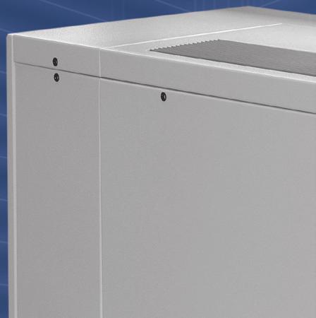
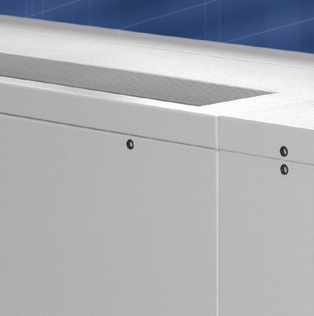
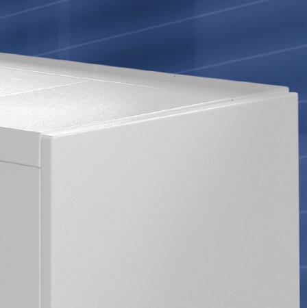
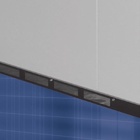
4 General Description Valedictorian Vertical Unit Ventilator Tamper-Proof Cabinet Locks 14 Gauge Steel Panels Pencil-Proof Aluminum Bar Grill Baked-On Epoxy Paint Removable Front Panels STANDARD FEATURES Overview The Valedictorian vertical unit ventilator is the perfect solution for both new construction and replacement of existing units in schools that want to improve the indoor air quality of their classrooms. It operates in conjunction with a schools central chiller/boiler plant and is available in Face & Bypass and Valve Control configurations. A variety of coil options and adapter backs make it easy to select the right unit for the job. General Specification The unit shall be a unit ventilator configured for one of the following cooling/heating options: chilled water cooling/hot water heating, DX cooling only, combined chilled water cooling and hot water or steam heating, or combined DX cooling and hot water or steam heating. The unit shall be floormounted and horizontally configured with adjustable leg levels. The unit shall have a pencil-proof clear anodized aluminum supply air bar grill and ¼ galvanized steel mesh mounted on the top panel. All access and maintenance shall be through the front and the top side panels of the unit. The unit shall be constructed and listed in accordance with ETL and CSA standards (ANSI/UL , second edition) (CAN/CSA C22.2 NO ). The unit shall be constructed following ISO: 9001 quality control program procedures and be fully assembled and tested prior to shipment. Cabinet Prior to assembly, the cabinet parts shall be degreased and coated with a dry powder, epoxy resin paint, baked after application, standard color shall be beige with hammertone textured finish. The paint finish shall be easily cleanable and hard wearing to give maximum protection. The cabinet shall be insulated with acoustic foam insulation containing no fibrous materials. The foam insulation shall have a fire rating of UL94 HF1. The exterior panels of the cabinet shall be constructed of 14 gauge sheet steel. Internal sheet metal shall be galvanized 16 gauge. The front panel and compartment panels shall be easily removable with tamperproof fasteners securing it to the rest of the unit cabinet. The back of the cabinet shall have an opening for connection to a wall sleeve and louver. 4
5 Control Panel The control panel is located in the left-hand compartment. All components located in the panel shall be clearly marked for easy identification. All terminal blocks and wires shall be individually numbered. All electrical wires in the control panel shall be run in an enclosed trough. Wiring outside the control panel shall be run in protective sleeves. The unit shall be fitted with a power disconnect switch sized for the full load amperage of the unit to enable the unit to be disconnected from the power supply prior to any maintenance. The 3-speed selector switch enables adjustment of the supply air volume. Reduction in fan speed shall be achieved by a step down multi-tap transformer. Water/Steam Coils Large surface area slab coils shall be utilized to optimize heat transfer and airflow. Each coil shall be manufactured from refrigeration quality 3/8 diameter copper tubing mechanically bonded onto aluminum Highmix fins with coil circuitry designed to ensure minimum waterside pressure drops. Each coil shall be fitted with an air bleed at the high point of the coil and a drain plug at the low point. Evaporator Drain Pan Supply Fan & Fan Motor All direct expansion units include a factory installed thermal expansion valve and utilize large surface area evaporator coils ideally positioned to optimize heat transfer and airflow. Each evaporator is manufactured from refrigeration quality copper tubes with mechanically bonded aluminum fins. Evaporator coils shall include a factory installed low limit stat. Each unit shall be fitted with a 20 gauge, 304 stainless steel welded construction drain pan sloped in 3 directions. The drain pan connection shall be reversible in the field to switch drain orientation and include ¾ reinforced condensate tubing and splashguard over the drain port. Supply airflow shall be provided by double inlet, forward curved, centrifugal type fan with offset aerodynamic blades. The assembly shall be statically and dynamically balanced to ensure smooth running and minimum noise levels. The fan motor shall be a permanent split capacitor type complete with integral automatic thermal overload protection. The fan and motor assembly shall be direct drive type with motor and bearings positioned outside of the airstream. The fan assembly shall be positioned for a draw through configuration. Filter Dampers Throwaway 1 thick filters shall be provided and installed at the factory and located to provide filtration of both the outdoor and return air prior to being conditioned. Each unit shall be fitted with separate outside air and return air dampers. The dampers shall have the capability of permitting only the outside air into the space, or recycling the return air and allowing only a minimum of outside air to enter the space. Full modulation allowing any mixture of outside air and return air shall be possible. A minimum damper position setting shall also be possible to continuously maintain outside air ventilation requirements dependent on control via the unit s microprocessor controller. The outside air damper is constructed of galvanized steel and the return air damper is constructed of aluminum. Dampers shall be gasketed to prevent air bypass and shall pivot on self-lubricating nylon bearings. Each unit shall be fitted with an optional factory installed face & bypass damper constructed of aluminum and braced for rigidity. The damper shall include EPDM rubber end seal and F3 wool felt side seals. The damper shall be removable to allow access to the coil(s). Not available on DX Cooling units. 5
6 Options Factory Installed DDC Ready Controls Factory installed DDC ready controls shall include a fan relay, 24-volt control circuit transformer and terminal strip. Units with DX cooling shall also include an evaporator low-limit stat. Controls also include a 2-10Vdc outside air and/or face & bypass damper actuator where applicable. All components located in the panel shall be clearly marked for easy identification. All terminal blocks and wires shall be individually numbered. All electrical wires in the control panel shall be run in an enclosed trough. Wiring outside the control panel shall be run in protective sleeves. The unit shall be fitted with a power disconnect switch sized for the full load amperage of the unit to enable the unit to be disconnected from the power supply prior to any maintenance. A 3-speed selector switch shall be mounted internally enabling adjustment of the supply air volume. Reduction in fan speed shall be achieved by a step down multi-tap transformer. Factory Installed Carel Controls Factory installed Carel controls shall include a fan relay, 24-volt control circuit transformer, terminal strip and Carel microprocessor controller, return air, outside air and supply air sensors. Units with DX cooling shall also include an evaporator low-limit stat. Controls also include a 2-10Vdc outside air and/or face & bypass damper actuator where applicable. The controller is mounted outside the air stream and specifically designed to operate the unit in an energy efficient manner using preengineered control strategies. The microprocessor shall determine the mode of operation based on the return air, supply air and ambient air temperatures. All components located in the panel shall be clearly marked for easy identification. All terminal blocks and wires shall be individually numbered. All electrical wires in the control panel shall be run in an enclosed trough. Wiring outside the control panel shall be run in protective sleeves. The unit shall be fitted with a power disconnect switch sized for the full load amperage of the unit to enable the unit to be disconnected from the power supply prior to any maintenance. A 3-speed selector switch shall be mounted internally enabling adjustment of the supply air volume. Reduction in fan speed shall be achieved by a step down multi-tap transformer. Carel Controls Lonworks Plug-In Card The Carel microprocessor controls shall come equipped with a plug-in card allowing for complete compatibility with FT-10 Lonworks control system. Carel Controls BACnet Plug-In Card The Carel microprocessor controls shall come equipped with a plug-in card allowing for complete compatibility with an MS/TP BACnet control system. Carel Time Clock / Card A time clock (card) shall be provided for stand-alone units where time functions, night and weekend setback, etc. are not transmitted from a building management system or remote central time clock. The time clock shall have a full 7 day schedule and calendar function incorporated. The 7 day schedule shall have two adjustable occupied/unoccupied periods per day. The calendar function shall allow 20 calendar periods (start date / stop date = 1 period). Carel Display Module Water Coil Freeze Protection CO 2 Sensor Aquastat For units fitted with the Carel controls, a hand-held display module shall be supplied for set point changes, control adjustments, error acknowledgement and unit troubleshooting. The unit shall be fitted with a freeze protection sensor mounted on the discharge side of the first coil to prevent any freezing of the first coil assembly. When the sensor detects a freeze up condition it shall shut the damper and force the flow control valve open and prevent the unit supply fan from running. The CO 2 sensor shall be mounted in the interior return air passage of the unit to provide demand ventilation. When the level of CO 2 rises over a predetermined set point, the sensor shall proportionally adjust the minimum damper position to allow larger quantities of outside air into the room. The sensor shall have the capability of measuring CO 2 levels from 0 to 2,000 ppm with an accuracy of + 40 ppm CO % of the reading. An aquastat shall be fitted to two pipe systems to prevent changeover into a heating mode when cooling is required and vice-versa. 6
7 Condensate Pump Condensate Pan Float Switch Fire Detection Smoke Detector The unit shall be fitted with a condensate pump. The pump shall have a 1/30 th hp motor capable of 20 gph at 15 feet of lift with rustproof, ABS plastic tank with built-in flow check valve and safety switch. The unit shall be fitted with a float switch mounted on the condensate pan to stop the cooling function should the condensate rise to a predetermined level. The unit shall be fitted with a liquid element fire detection mounted in the return air stream to prevent the unit from operating if the return air temperature should rise above the setting on the element. The temperature setting on the fire detector element shall be adjustable. The unit shall be fitted with a smoke detector mounted in the return air stream. If smoke is present the unit will be shut down automatically. Carel Room Sensor For units fitted with the Carel microprocessor controller, a temperature sensor and set point adjustment module with override button shall be furnished for wall mounting. Carel Thermostat For units fitted with the Carel microprocessor controller, a digital thermostat shall be furnished for wall mounting. Insulated Damper Assembly EC Motor The outside air damper shall be insulated with ½ thick insulation to inhibit condensation on the damper surface. The fan motor shall be an electronically commutated motor (ECM). The ECM provides constant airflow by automatically adjusting the speed if the external static pressure changes. The DC motor features a brushless, permanently lubricated ball bearing construction for maintenance free operation. The ECM shall also be fully programmed to compensate for a wide variety of static pressures as well as lack of maintenance (dirty air filters). 7
8 Accessories Field Installed Modulating Control Valve 2-Position Spring Return Control Valve Two-way or three-way modulating valve(s) shall be provided for precise capacity control of hot water and/or chilled water coil(s). The capacity control valve(s) shall be controlled by a 2-10Vdc signal from the unit mounted controller and shipped loose for field installation. Two-way or three-way 2-position spring return control valve(s) shall be provided for control of hot water and/or chilled water coil(s). The control valve(s) shall be controlled by a 24V signal from the units control panel and shipped loose for field installation. Balancing Valve A heavy duty forged brass ball-valve construction balancing valve shall be supplied loose for field installation. Circuit Setter Drain with Hose Bib A manually adjustable ball-valve construction balancing valve with Schrader style pressure ports and drain port shall be supplied loose for field installation. A blowdown valve with hose connector and cap shall be mounted on the coil. Shut-Off Valves Strainer A set of two heavy duty forged brass ball valves, one for the supply and one for the return, shall be supplied loose for field installation. A heavy duty cast iron strainer with 20 mesh 304 stainless steel screen, gasketed and tapped retainer cap and blow-off outlet shall be supplied loose for field installation. Factory Assembled Piping The selected piping components shall be factory assembled, with all the necessary piping and unions, and shipped separately to be field installed inside the side compartment and outside of the airstream of the unit ventilator. Side Panels Utility Compartment Factory supplied side panels constructed of 14 gauge sheet steel and painted to match the unit shall be field mounted to the base unit. Side panels are available for both 16 5/8 and 21 7/8 deep units with or without pipe passage cutouts. A factory supplied utility compartment with 14 gauge sheet steel front and top panels and painted to match the unit shall be field mounted to the base unit. Utility compartments are available for both 16 5/8 and 21 7/8 deep units in 12, 18 and 24 widths. Filler Section Unit Sub-Base Utility Compartment Sub-Base Wall Sleeve A factory supplied filler section constructed of 16 gauge sheet steel and painted to match the unit shall be field mounted. Filler sections are available in 6, 12 and 18 widths and can be field cut for custom widths. Unit height adjustments can be made in increments of 1, 2, 4 and 6 with a sub-base field mounted under the standard unit. The sub-base is fully enclosed, constructed of heavy duty steel and painted to match the base of the standard unit. Utility compartment height adjustments can be made in increments of 1, 2, 4 and 6 with a sub base field mounted under the standard utility compartment. The sub base is fully enclosed, constructed of heavy duty steel and painted to match the base of the standard utility compartment. The wall sleeve shall be constructed from galvanized steel. The sleeve shall be provided by Modine and insulated by the installing contractor with foil back insulation. Outdoor Louver An outdoor louver shall be furnished by Modine and be suitable for masonry, glass, or panel wall construction. The louvers are flanged style with 42 degree,.040 thick blades with inch blade spacing and shall be available in the following materials: 1. Aluminum with clear anodized finish 2. Aluminum with baked enamel finish, customer selected from manufacturer s standard louver color chart All louvers can be provided with a bird screen 8
9 Duct Flange A 1 duct flange shall be supplied and field installed to allow for easy installation of a supply air duct to the unit. Spare Filters One spare filter shall be supplied with the unit. Figure 9.1 Component Layout Control Panel Freeze Stat (Optional) Blower Motor Face & Bypass Damper Actuator (Optional) Field Installed Piping Outside Air/Return Air Damper Actuator (Optional) Face & Bypass Damper (Optional) Filters Blowers Power Connection, Disconnect Switch and 3-Speed Fan Switch 9
10 Valve Control Units In a Valve Control Unit all of the air passes through the coil. The flow of water through the coil is modulated to maintain the set point temperature in the room. 1. Air is drawn through the unit by the blowers (draw-through design), conditioned and supplied to the room. 2. Return air enters through the lower front kick panel of the unit and outside air enters through the lower back panel of the unit. 3. The percentage of outside air and return air is controlled by the position of the outside air and return air dampers. 4. Air passes through the filters and then through the coil. The air is conditioned as it passes through the coil. 5. Cooling or heating is controlled by adjusting the flow of water through the coil with a modulating valve. Face & Bypass Units In a Face & Bypass Unit the outside air and return air can be separated, to condition only the outside air, or mixed before passing through the coil. Water flow and coil temperature remain constant to provide maximum dehumidification and low risk of coil freezing. The face & bypass damper is modulated to maintain the set point temperature in the room. Figure 10.1 Valve Control Unit 2 OA SA Figure 10.2 Face & Bypass Unit SA Air is drawn through the unit by the blowers (draw-through design), conditioned or bypassed and supplied to the room. 2. Return air enters through the lower front kick panel of the unit and outside air enters through the lower back panel of the unit. 3. The percentage of outside air and return air is controlled by the outside air and return air dampers. 4. Air passes through the filters and then either passes through the coil or is diverted to bypass the coil. The air passing through the coil is conditioned. Bypassed air is mixed with the conditioned air and delivered to the room. 5. Cooling or heating is controlled by adjusting the face & bypass damper. 2 OA
11 Figure 11.1 Dimensional Data 16 5/8 Unit 1.02 (TYP) (TYP) REMOVABLE BOTTOM PANEL (EACH END) (TYP) W (TYP) 6.60 TOP VIEW 1.78 BARSTOCK DISCHARGE GRILLE 1.09 (UNIT SHOWN WITH 1.09" END PANELS) (TYP) W1 MOTOR CONTROL BOX ELECTRICAL BOX PIPE TUNNEL FRONT SERVICE PANELS FRONT VIEW 3.18 RECESSED RETURN AIR/KICK PANEL RIGHT SIDE VIEW 6.61 (TYP) REMOVABLE PANEL (EACH END) PIPE TUNNEL (TYP) 2.56 (TYP) PIPING ACCESS OPENING (EACH END) 7.00 (TYP) (TYP) (TYP) W (TYP) (TYP) O.88 (MOUNTING HOLES-TYP- 4 PLACES) 4.50 OUTSIDE AIR OPENING REAR VIEW (TYP) 2.78 (TYP) Table 11.1 Unit Width Dimensions Model Size Dimensions (inches) W1 W2 W
12 Figure 12.1 Dimensional Data 21 7/8 Unit 6.36 (TYP) (TYP) REMOVABLE BOTTOM PANEL (EACH END) (TYP) W (TYP) 6.60 TOP VIEW 1.78 W1 BARSTOCK DISCHARGE GRILLE (UNIT SHOWN WITH 1.09" END PANELS) (TYP) MOTOR CONTROL PANEL ELECTRICAL BOX PIPE TUNNEL FRONT SERVICE PANELS FRONT VIEW 3.12 RECESSED RETURN AIR/KICK PANEL RIGHT SIDE VIEW 6.61 (TYP) REMOVABLE PANEL (EACH END) PIPE TUNNEL (TYP) 2.56 (TYP) PIPING ACCESS OPENING (EACH END) 7.00 (TYP) (TYP) (TYP) W (TYP) (TYP) O.88 (MOUNTING HOLES-TYP- 4 PLACES) 4.12 OUTSIDE AIR OPENING REAR VIEW 4.97 (TYP) 2.78 (TYP) Table 12.1 Unit Width Dimensions Model Size Dimensions (inches) W1 W2 W
13 Figure 13.1 Inlet Air Arrangements for 16 5/8 Units A. Rear Outside Air Open Pipe Tunnel B. Rear Outside Air Closed Pipe Tunnel CLOSED PIPE TUNNEL OPEN PIPE TUNNEL SHOWN WITH OPTIONAL SIDE PANELS SHOWN WITH OPTIONAL SIDE PANELS OUTSIDE AIR INLET OUTSIDE AIR INLET C. Bottom Outside Air Open Pipe Tunnel D. No Outside Air Open Pipe Tunnel OPEN PIPE TUNNEL OPEN PIPE TUNNEL SHOWN WITH OPTIONAL SIDE PANELS SHOWN WITH OPTIONAL SIDE PANELS CLOSED BACK CLOSED BACK FRONT BOTTOM VIEW 5.50 REAR OUTSIDE AIR OPENING W Table 13.1 Unit Dimensions Model Size Dimensions (inches) W
14 Figure 14.1 Inlet Air Arrangements for 21 7/8 Units E. Rear Outside Air Open Pipe Tunnel F. Rear Ouside Air Closed Pipe Tunnel OPEN PIPE TUNNEL CLOSED PIPE TUNNEL SHOWN WITH OPTIONAL SIDE PANELS SHOWN WITH OPTIONAL SIDE PANELS OUTSIDE AIR INLET OUTSIDE AIR INLET W5 W5 G. Top Window Intake Closed Pipe Tunnel CLOSED PIPE TUNNEL H. Bottom Outside Air Closed Pipe Tunnel OPEN PIPE TUNNEL 3.83 W2 SHOWN WITH OPTIONAL SIDE PANELS SHOWN WITH OPTIONAL SIDE PANELS OUTSIDE AIR INLETS W5 CLOSED BACK FRONT BOTTOM VIEW 3.75 REAR OUTSIDE AIR OPENING W Table 14.1 Unit Dimensions Model Size Dimensions (inches) W2 W
15 Figure 15.1 Inlet Air Arrangements for 21 7/8 Units J. Closed Back Closed Pipe Tunnel CLOSED PIPE TUNNEL (NOT SHOWN) K. 2 Step-Down Open Pipe Tunnel 2.00 OPEN PIPE TUNNEL SHOWN WITH OPTIONAL SIDE PANELS SHOWN WITH OPTIONAL SIDE PANELS CLOSED BACK L. 2 Step-Down Closed Pipe Tunnel OUTSIDE AIR INLET W CLOSED PIPE TUNNEL SHOWN WITH OPTIONAL SIDE PANELS OUTSIDE AIR INLET W5 Table 15.1 Unit Dimensions Model Size Dimensions (inches) W
16 Figure 16.1 Chilled Water Coil with Optional Reheat Piping Locations Chilled Water Coil Only, 2-Pipe Chilled Water/Hot Water Coil, or Chilled Water Coil with Reheat Coil LEFT HAND CONNECTIONS RIGHT HAND CONNECTIONS A REHEAT COIL S CHILLED WATER COIL R R CHILLED WATER COIL REHEAT COIL S E C DIN DIN G.88 D B S = Supply R= Return F H.88 Table 16.1 Chilled Water Coil with Optional Reheat Piping Locations Unit Coil Dimensions (inches) Depth Rows A B C D E F G H 2-Row /8 3-Row Row Row /8 3-Row Row For Hot Water Reheat piping location see figure For Steam Reheat Piping location see figure Figure 16.2 Chilled Water Coil with Pre-Heat Piping Locations Chilled Water Coil with Pre-Heat Coil Only LEFT HAND CONNECTIONS RIGHT HAND CONNECTIONS B F A D S CHILLED WATER COIL R PREHEAT COIL R CHILLED WATER COIL PREHEAT COIL S H E C G DIN DIN.88 S = Supply R= Return.88 Table 16.2 Chilled Water Coil with Pre-Heat Piping Locations Unit Coil Dimensions (inches) Depth Rows A B C D E F G H 2-Row /8 3-Row Row Row /8 3-Row Row For Hot Water Pre-Heat piping location see figure For Steam Pre-Heat Piping location see figure
17 Figure 17.1 DX Cooling (Size 750 Only) with Optional Reheat Piping Locations Size 750 DX Cooling Coil Only or DX Cooling Coil with Reheat Coil LEFT HAND CONNECTIONS RIGHT HAND CONNECTIONS HEATING COIL DX COIL SL LL HEATING COIL LL SL DIN DX COIL DIN B A LL = Liquid Line SL = Suction Line D C.88 Table 17.1 DX Cooling Coil Piping Locations Dimensions (inches) Unit Depth Model Size A B C D 16 5/ / For Hot Water Reheat piping location see Figure For Steam Reheat piping location see Figure Figure 17.2 DX Cooling (Size 750 Only) with Pre-Heat Piping Locations Size 750 DX Cooling Coil with Pre-Heat Coil Only LEFT HAND CONNECTIONS RIGHT HAND CONNECTIONS C A DX COIL SL LL D B LL SL HEATING COIL HEATING COIL DX COIL DIN DIN.88 LL = Liquid Line SL = Suction Line.88 Table 17.2 DX Coil with Pre-Heat Piping Locations Dimensions (inches) Unit Depth Model Size A B C D 16 5/ / For Hot Water Pre-Heat piping location see Figure For Steam Pre- Heat piping location see Figure
18 Figure 18.1 DX Cooling with Optional Reheat Piping Locations Size 1000, 1250, 1500 DX Cooling Coil Only or DX Cooling Coil with Reheat Coil LEFT HAND CONNECTIONS RIGHT HAND CONNECTIONS HEATING COIL LL DX COIL SL LL HEATING COIL DX COIL SL DIN DIN.88 B A LL = Liquid Line SL = Suction Line D C.88 Table 18.1 DX Cooling Coil Piping Locations Dimensions (inches) Unit Depth Model Size A B C D 16 5/8 1000, 1250, /8 1000, 1250, For Hot Water Reheat piping location see Figure For Steam Reheat piping location see Figure Figure 18.2 DX Cooling with Pre-Heat Piping Locations Size 1000, 1250, 1500 DX Cooling Coil with Pre-Heat Coil Only LEFT HAND CONNECTIONS C A DX COIL SL LL D B LL SL HEATING COIL HEATING COIL DX COIL DIN DIN.88 LL = Liquid Line SL = Suction Line.88 Table 18.2 DX Coil with Pre-Heat Piping Locations Dimensions (inches) Unit Depth Model Size A B C D 16 5/8 1000, 1250, /8 1000, 1250, For Hot Water Pre-Heat piping location see Figure For Steam Pre-Heat piping location see Figure
19 Figure 19.1 Hot Water Heating Coil Piping Locations Hot Water Heating Coil Only or Chilled Water/DX Cooling Coil with Hot Water Pre-Heat Coil LEFT HAND CONNECTIONS RIGHT HAND CONNECTIONS A COOILNG COIL S HOT WATER COIL R R HOT WATER COIL COOLING COIL S E C DIN DIN G.88 D B S = Supply R= Return F H.88 Table 19.1 Hot Water Heating Coil Piping Locations Unit Coil Dimensions (inches) Depth Rows A B C D E F G H 16 5/8 1-Row Row /8 1-Row Row For Chilled Water piping location see Figure For DX Cooling piping location see Figure 17.2 and Figure 19.2 Hot Water Reheat Coil Piping Locations Chilled Water/DX Cooling Coil with Hot Water Reheat Coil Only LEFT HAND CONNECTIONS RIGHT HAND CONNECTIONS B F A D S HOT WATER COIL R COOLING COIL R HOT WATER COIL COOLING COIL S H E C G DIN DIN S = Supply R= Return Table 19.2 Hot Water Reheat Coil Piping Locations Unit Coil Dimensions (inches) Depth Rows A B C D E F G H 16 5/8 1-Row Row /8 1-Row Row For Chilled Water piping location see Figure For DX Cooling piping location see Figure 17.1 and
20 Figure 20.1 Steam Heating Coil Piping Locations Steam Heating Coil Only or Chilled Water/DX Cooling Coil with Steam Pre-Heat Coil LEFT HAND CONNECTIONS RIGHT HAND CONNECTIONS COOLING COIL COOLING COIL R STEAM COIL S S COOLING COIL STEAM COIL R DIN DIN B S = Supply B A A R= Return Table 20.1 Steam Heating Coil Piping Locations Dimensions (inches) Unit Depth Coil Rows A B 16 5/8 1-Row /8 1-Row For Chilled Water piping location see Figure For DX Cooling piping location see Figure 17.2 and Figure 20.2 Steam Reheat Coil Piping Locations Chilled Water/DX Cooling Coil with Steam Reheat Coil Only LEFT HAND CONNECTIONS RIGHT HAND CONNECTIONS A S S A B R STEAM COIL COOLING COIL STEAM COIL COOLING COIL R B DIN DIN.88 S = Supply R= Return.88 Table 20.2 Steam Reheat Coil Piping Locations Dimensions (inches) Unit Depth Coil Rows A B 16 5/8 1-Row /8 1-Row For Chilled Water piping location see Figure For DX Cooling piping location see Figure 17.1 and
21 Table 21.1 Cooling Capacity (Btu/Hr) Unit Size EWT ( F) Flow Rate (GPM) Number of Rows PD (ft) Capacity Type (Btu/Hr) Airflow CFM High Medium Low Entering Air Temp (EDB/EWB F) 80/ Total 18,312 17,071 14,694 Sensible 14,965 13,694 11, Total 26,160 24,388 20,991 Sensible 18,707 17,118 14, Total 27,520 25,656 22,083 Sensible 19,109 17,486 14, Total 21,297 19,255 16,392 Sensible 16,533 14,908 12, Total 30,424 27,508 23,417 Sensible 20,666 18,635 15, Total 32,006 28,938 24,634 Sensible 21,110 19,036 15, Total 27,859 24,376 21,468 Sensible 22,876 19,163 16, Total 32,775 28,678 25,256 Sensible 24,080 20,172 17, Total 34,454 30,147 26,550 Sensible 24,461 20,490 17, Total 32,099 28,494 25,835 Sensible 25,955 21,442 19, Total 37,763 33,523 30,394 Sensible 27,321 22,571 20, Total 39,698 35,240 31,951 Sensible 27,752 22,927 20, Total 32,871 28,391 25,135 Sensible 27,608 22,624 19, Total 38,671 33,401 29,571 Sensible 29,061 23,814 20, Total 40,652 35,112 31,085 Sensible 29,520 24,191 20, Total 39,623 32,737 29,067 Sensible 30,868 24,748 21, Total 46,616 38,514 34,197 Sensible 32,493 26,050 22, Total 49,004 40,487 35,949 Sensible 33,006 26,462 23, Total 37,455 32,871 29,721 Sensible 32,186 26,797 23, Total 44,064 38,672 34,966 Sensible 33,880 28,207 24, Total 46,356 40,683 36,784 Sensible 34,601 28,808 25, Total 45,709 38,736 34,125 Sensible 36,205 29,616 25, Total 53,775 45,572 40,147 Sensible 38,111 31,175 26, Total 56,572 47,942 42,235 Sensible 38,922 31,839 27,562 For additional capacity information, please consult the Breeze AccuSpec software. 21
22 Table 22.1 Unit Size 750 Direct Expansion Cooling Capacity (Btu/Hr) Evaporator Saturation Temperature F Airflow CFM Entering Air Dry Bulb/Wet Bulb F 85/71 80/67 75/63 85/71 80/67 75/63 85/71 80/67 75/63 TC MBH 34,325 28,463 23,036 30,940 25,669 20,786 26,407 21,928 17,782 SC MBH 19,042 16,960 14,849 17,163 15,294 13,396 14,644 13,059 11,451 LDB ºF LWB ºF TC MBH 29,630 23,766 18,430 26,724 21,446 16,644 22,829 18,345 14,258 SC MBH 16,780 14,708 12,614 15,132 13,268 11,386 12,918 11,339 9,740 LDB ºF LWB ºF TC MBH 24,542 18,802 13,605 22,147 16,981 12,296 18,944 14,547 10,546 SC MBH 14,563 12,510 10,432 13,137 11,291 9,421 11,223 9,657 8,066 LDB ºF LWB ºF Performance based on 105 F Liquid Inlet Temperature. Table 22.2 Unit Size 1000 Direct Expansion Cooling Capacity (Btu/Hr) Evaporator Saturation Temperature F Airflow CFM Entering Air Dry Bulb/Wet Bulb F 85/71 80/67 75/63 85/71 80/67 75/63 85/71 80/67 75/63 TC MBH 46,343 37,911 30,215 38,144 31,142 24,804 32,848 26,875 21,463 SC MBH 25,801 22,727 19,661 21,237 18,671 16,132 18,291 16,116 13,953 LDB ºF LWB ºF TC MBH 39,763 31,423 24,087 32,749 25,860 19,781 28,192 22,328 17,087 SC MBH 22,688 19,649 16,660 18,688 16,160 13,676 16,092 13,946 11,806 LDB ºF LWB ºF TC MBH 32,716 24,757 17,677 26,996 20,380 14,494 23,246 17,559 12,483 SC MBH 19,634 16,669 13,698 16,189 13,706 11,232 13,934 11,802 9,675 LDB ºF LWB ºF Performance based on 105 F Liquid Inlet Temperature. TC = Total Capacity SC = Sensible Capacity LDB = Leaving Dry Bulb LWB = Leaving Wet Bulb 22
23 Table 23.1 Unit Size 1250 Direct Expansion Cooling Capacity (Btu/Hr) Evaporator Saturation Temperature F Airflow CFM Entering Air Dry Bulb/Wet Bulb F 85/71 80/67 75/63 85/71 80/67 75/63 85/71 80/67 75/63 TC MBH SC MBH LDB ºF LWB ºF TC MBH SC MBH LDB ºF LWB ºF TC MBH SC MBH LDB ºF LWB ºF Performance based on 105 F Liquid Inlet Temperature. Table 23.2 Unit Size 1500 Direct Expansion Cooling Capacity (Btu/Hr) Evaporator Saturation Temperature F Airflow CFM Entering Air Dry Bulb/Wet Bulb F 85/71 80/67 75/63 85/71 80/67 75/63 85/71 80/67 75/63 TC MBH 71,293 58,404 46,636 57,981 47,427 37,803 50,287 41,211 32,891 SC MBH 39,581 34,844 30,138 32,198 28,311 24,452 27,930 24,610 21,290 LDB ºF LWB ºF TC MBH 61,240 48,405 37,142 49,855 39,329 30,174 43,229 34,188 26,276 SC MBH 34,743 30,066 25,490 28,303 24,455 20,712 24,552 21,257 18,037 LDB ºF LWB ºF TC MBH 50,283 38,162 27,273 41,040 31,073 22,195 35,610 27,006 19,326 SC MBH 29,992 25,478 20,972 24,471 20,749 17,051 21,229 18,034 14,838 LDB ºF LWB ºF Performance based on 105 F Liquid Inlet Temperature. TC = Total Capacity SC = Sensible Capacity LDB = Leaving Dry Bulb LWB = Leaving Wet Bulb 23
24 Table 24.1 Heating Capacity (Btu/Hr) Unit Size EWT ( F) Flow Rate (GPM) Number of Rows PD (ft) Airflow CFM High Medium Low Heating Return Air Temp (EDB F) ,386 34,752 28, ,110 45,366 37, ,261 51,840 42, ,152 55,363 45, ,823 37,438 30, ,596 48,872 39, ,388 55,847 45, ,627 59,642 48, ,804 40,803 34, ,381 51,107 43, ,442 59,350 50, ,135 66,472 56, ,685 44,005 36, ,494 55,118 46, ,541 64,008 53, ,086 71,689 59, ,656 47,744 41, ,550 62,065 54, ,437 70,778 61, ,226 79,413 69, ,035 51,738 44, ,843 67,258 58, ,893 76,700 66, ,836 86,057 74, ,109 57,236 49, ,625 75,619 65, ,573 84,557 72, ,959 88,594 76, ,277 62,508 53, ,417 82,584 70, ,640 92,344 78, ,653 97,146 82,978 For additional capacity information, please consult the Breeze AccuSpec software. 2-pipe chilled water / hot water units 24
25 25 Table 25.1 Steam Heating Capacity at 2 lb. Steam (Btu/Hr) Entering Air Temp ºF Steam heating performance based on 2psig steam Table 25.2 Steam Capacity and Leaving Air Temperature Correction Factors Entering Air Temp ºF \ Airflow CFM HIGH MED LOW HIGH MED LOW HIGH MED LOW HIGH MED LOW Size Steam Pressure psig
26 Table 26.1 Technical Data VFF & VFV Units SUPPLY FAN Direct Drive Centrifugal Fan Quantity Fan Diameter Fan Width Standard Motor Size (Qty 1) hp 1/4 1/4 1/4 1/4 Standard Motor Type PSC with Thermal Overload Protection Airflow (High/Medium/Low) cfm 750/650/ /750/ /900/ /1100/900 Max External Static Pressure in.wg COIL WATER VOLUME 1 Row gal Row gal Row gal Row gal CONNECTIONS Water Coils Inches Unions with 3/4 female solder joint Evaporator Coil Inches 3/4 OD Suction, 1/2 OD Liquid Steam Coil Inches 1 NPT Condensate Line Inches 3/4 ID condensate line UNIT WEIGHT (approximate) Shipping Weight 16 5/8 Units lbs Operating Weight 16 5/8 Units lbs Shipping Weight 21 7/8 Units lbs Operating Weight 21 7/8 Units lbs FILTER 1 Woven Fiberglass, 70-75% Arrestance Quantity Dimensions in. 10 X X X X 36 Table 26.2 Chilled Water Cooling Capacity Model Rows Total Sensible Total Sensible Total Sensible Total Sensible 2 18,494 15,985 26,570 22,239 34,943 28,620 43,437 35, ,248 17,914 34,532 24,829 45,124 31,894 55,621 38, ,248 18,499 37,404 25,651 48,576 32,845 59,662 40,230 Notes: 1. Rated in accordance with ARI Standard Water temperature rise is 10 F, with entering water temperature of 45 F. 3. Entering air temperature is 80 F dry bulb, 67 F wet bulb. Table 26.3 Hot Water Heating Capacity Model Rows Btu/h Btu/h Btu/h Btu/h 1 38,386 49,804 59,656 70, ,110 62,381 77,550 92, ,261 72,442 88, , ,152 81,135 99, ,959 Notes: 1. Water temperature is 160 F and 6 gpm water flow. 2. Entering air temperature is 60 F. 26
27 Table 27.4 Electrical Data 115V 208V 230V Motor Size FLA MCA MOP FLA MCA MOP FLA MCA MOP ¼ Hp Motor (Standard) ¼ Hp Motor with Condensate Pump ½ Hp EC Motor ½ Hp EC Motor with Condensate Pump Table 27.2 Sound Data Model Speed L M H L M H L M H L M H CFM dba Notes: 1. Rated in accordance with ARI Standard Sound power levels were recorded using ARI standard method. 3. Sound power levels were recorded with the unit running in full recirculation mode and a 3 row coil. 27
28 Controls Field Installed Controls by Others (Standard) Units come standard with a blower motor, a power disconnect switch and a 3-speed selector switch for adjustment of the supply air volume. All other controls, sensors and actuators must be supplied by others. Factory Installed DDC Ready Controls (Optional) In addition to the blower motor, power disconnect and 3-speed selector switch; the optional factory installed DDC ready controls include a fan relay, 24-volt control circuit transformer, coil freeze protection sensor and terminal strip. Controls also include a 2-10Vdc outside air and/or face & bypass damper actuator where applicable. Factory Installed Carel Controls (Optional) Units include the Factory Installed DDC Ready Controls listed above along with a Carel microprocessor controller, return air sensor, outside air sensor and supply air sensor. The microprocessor shall determine the mode of operation based on the return air, supply air and ambient air temperatures. Control Sequence Supply Fan The supply fan shall run at all times when unit is in occupied mode. When in unoccupied mode, the supply fan shall run only on a call for heating or cooling. The supply fan speed can be adjusted using the standard equipped manual 3-speed switch. If equipped with a Carel controller, the supply fan is programmed to run for 2 minutes (adjustable) after the heating or cooling cycle ends. Freeze Stat On chilled water and hot water units equipped, an adjustable auto-resetting freeze stat is factory set to trip at 35 F. If the coil temperature reaches the limit and the freeze stat trips, it shall reset when the coil temperature rises 5 F above the setpoint. The freeze stat shall be wired so that upon tripping, power is removed from the supply fan, the outside air damper closes, and either the HW valve opens or the face & bypass damper goes to full bypass (depending on how unit is equipped). Outside Air and Return Air Dampers The outside air and return air dampers control the mixture of return air and outside air drawn through the unit. Both dampers are linked together and are controlled by an actuator requiring a 2-6VDC proportional signal. At 2V, the dampers are positioned for full return air and no outside air. At 6V, the dampers are positioned for full outside air and no return air. The outside air damper shall open to a minimum position to provide ventilation requirements when the room is occupied. When in heating mode, if the space temperature is more than 4 F from the heating setpoint, the outside air damper shall fully close. The outside air damper shall also be fully closed during unoccupied mode. If the unit is equipped with a CO 2 sensor, the outside air damper shall modulate open proportionally to compensate for the CO 2 levels in the room. The dampers can act as economizers for free-cooling. If cooling is required and the outside air temperature is below the economizer outside air lockout temperature (recommended 60 F) and above 35 F, the outside air damper shall modulate open. On units with a Carel controller, the outside air damper shall fully open when the room temperature is above the setpoint by more than 1 F (adjustable). Within 1 F, the proportional band adjusts the outside air damper. When the unit is in free-cooling, water valves shall be fully closed, and if equipped, the face & bypass damper should move to full bypass position. The outside air lockout temperature on Carel units is factory set to 60 F and is adjustable. 28
29 Control Sequence Continued Chilled Water with Valve Control Units with a chilled water coil and non-carel controls desiring valve control shall use a non-spring return modulating valve operated by either a proportional (2-10VDC) or a tri-state (24VAC) signal. Units with a chilled water coil and Carel controls desiring valve control shall use a modulating valve requiring a tri-state signal. When the room temperature is above the cooling setpoint, the valve shall open proportionally according to the adjustable proportional band. The adjustable proportional band on the Carel controller is set to a default 1 F (ex. valve is 50% open when room temperature is 0.5 F from setpoint). The Carel controller will not allow the chilled water valve to open when the outside air temperature is below 55 F. Hot Water or Steam with Valve Control Units with a hot water or steam coil and non-carel controls desiring valve control shall use a spring-return, normally open modulating valve operated by a proportional signal (2-10VDC) or a tri-state (24VAC) signal. Units with Carel controls desiring valve control shall use a modulating control valve with a proportional signal. When the room temperature is below the heating setpoint, the valve shall open proportionally according to the adjustable proportional band. The adjustable proportional band on the Carel controller is set to a default 1 F (ex. valve is 50% open when room temperature is 0.5 F from setpoint). If for any reason the supply air temperature drops below 55 F, the valve shall modulate open to maintain 55 F. Direct Expansion (DX) Cooling Control When the room temperature is above the cooling setpoint, the compressor will be energized. The compressor will de-energize when the room temperature falls below the cooling setpoint. If the factory installed low limit stat detects indoor evaporator coil temperatures below its set point, the compressor will be disabled. Chilled Water with Face & Bypass Control Units equipped with a chilled water coil and face & bypass control shall modulate the face & bypass damper via a spring return actuator, controlled by a proportional signal (2-5.5V). The face & bypass damper regulates the amount of return air and outside air passing through the chilled water coil. On a call for cooling, the damper shall open to the face of the coil proportionally based on how many degrees the room temperature is from the setpoint. The adjustable proportional band on the Carel controller is set to a default 1 F (ex. damper is 50% open when room temperature is 0.5 F from setpoint). When the damper is in full bypass position (2V), all return and outside air bypasses the chilled water coil. When the damper is in full face position (5.5V), all return and outside air passes through the chilled water coil. Hot Water or Steam with Face & Bypass Control Units equipped with a hot water or steam coil and face & bypass control shall modulate the face & bypass damper via a spring return actuator, controlled by a proportional signal (2-5.5V). The face & bypass damper regulates the amount of return air and outside air passing through the heating coil. On a call for heating, the damper shall open proportionally based on how many degrees the room temperature is from the setpoint. The adjustable proportional band on the Carel controller is set to a default 1 F (ex. damper is 50% open when room temperature is 0.5 F from setpoint). When the damper is in full bypass position (2V), all return and outside air bypasses the heating coil. When the damper is in full face position (5.5V), all return and outside air passes through the heating coil. If for any reason the supply air temperature drops below 55 F, the heating valve shall open (if equipped) and the face and bypass damper shall modulate to maintain 55 F. Hot Water and Chilled Water (2-Pipe) with Valve Control Units desiring valve control to provide heating and cooling on a single water coil (2-pipe system) and not using Carel controls shall use a spring-return, normally open modulating valve operated by a proportional signal (2-10VDC) or a tri-state (24VAC) signal. Units with Carel controls shall use a modulating control valve with a proportional signal. On a call for heating or cooling (depending on the season), the valve shall open proportionally based on how many degrees the room temperature is from the setpoint. The adjustable proportional band on the Carel controller is set to a default 1 F (ex. valve is 50% open when room temperature is 0.5 F from setpoint). If for any reason the supply air temperature drops below 55 F, the water valve shall modulate open to maintain 55 F. On 2-pipe units not having Carel controls or not connected to a network, an optional aquastat is recommended to prevent inadvertent changeover of heating/cooling modes. 29
30 Control Sequence Continued Hot Water and Chilled Water (2-Pipe) with Face & Bypass Control Units desiring face and bypass control to provide heating and cooling on a single water coil (2-pipe system) shall modulate the face & bypass damper via a spring return actuator, controlled by a proportional signal (2-5.5V). The face & bypass damper regulates the amount of return air and outside air passing through the water coil. On a call for heating or cooling (depending on the season), the damper shall open proportionally based on how many degrees the room temperature is from the setpoint. The adjustable proportional band on the Carel controller is set to a default 1 F (ex. damper is 50% open when room temperature is 0.5 F from setpoint). When the damper is in full bypass position (2V), all return and outside air bypasses the water coil. When the damper is in full face position (5.5V), all return and outside air passes through the water coil. If for any reason the supply air temperature drops below 55 F, the water valve shall open (if equipped) and the face and bypass damper shall modulate to maintain 55 F. 2-Position Control Valves Optional spring-return, 2-position control valves can be used to control the end of cycle flow on chilled water, hot water, and steam coils. On a chilled water coil, a normally closed valve is used. On a hot water coil, steam coil, or 2-pipe changeover system, a normally open valve is used. The 2-position valve used on a chilled water coil shall open on a call for cooling when the outside air temperature is greater than 55 F. When the outside air temperature is less than 55 F, the valve should remain closed and free cooling shall be utilized. The 2-position chilled water valve shall be closed when the 2-position hot water or steam valve is open (when equipped). The valve is controlled by a 24VAC digital output. The 2-position valve used on a hot water or steam coil shall open on a call for heating. The valve shall always open when the outside air temperature drops below 40 F. This is to prevent the coil from freezing or nuisance tripping of the freeze stat. The heating valve shall be closed when the 2-position chilled water valve is open (if equipped). The valve is controlled by a 24VAC digital output. The 2-position valve used on a 2-pipe changeover system shall operate like the 2-position chilled water valve in cooling mode, and like the 2-position hot water valve in heating mode. Condensate Pump On units equipped with a condensate pump, the pump shall begin to run once the condensate reaches a set level. The pump comes with an internal safety switch that can be wired either normally open or normally closed. The safety switch shall be wired such that the chilled water valve closes when it trips. On Carel units, the switch shall be wired normally closed into a digital input of the controller. If the unit is also equipped with a condensate pan float switch, both switches shall be wired in series. Condensate Pan Float Switch On units equipped with a condensate pan float switch, the normally closed switch shall be wired such that the chilled water valve closes upon tripping. On Carel units, the switch shall be wired normally closed into a digital input of the controller. If the unit is also equipped with a condensate pump, both the condensate pump limit switch and condensate pan float switch shall be wired in series. CO 2 Sensor An optional CO 2 sensor with a range of ppm producing an output signal of 0-20mA is available to modulate the outside air damper. If equipped, the outside air damper shall modulate open proportionally to compensate for the CO 2 levels in the room. On Carel units, if the CO 2 level is 800 ppm or less, the damper shall remain at its normal minimum position. If the CO 2 level increases above 800 ppm, the damper begins to open according to the proportional band. The proportional band is set to a default of 200 ppm and is adjustable. Using the default, once the CO 2 level reaches 1000 ppm, the damper shall be at its maximum ventilation position. Fire Detector Units equipped with an optional fire detector shall shut down power to the supply fan and close all dampers upon the detection of a fire. Smoke Detector Units equipped with an optional smoke detector shall shut down power to the supply fan and close all dampers upon the detection of smoke. 30
31 Figure 31.1 Side Panels D = 16 5/8 or 21 7/8 Inches Full Side Panel D 7 Cut-Out D Cut-Out D Cut-Out D Step-Down Available in 21 7/8 Depth Only

32 Utility Compartments and Filler Sections Figure 32.1 Utility Compartments W = 12, 18 or 24 Inches 16 5/8 Utility Compartment 21 7/8 Utility Compartment 2 Step-Down Utility Compartment 2 W 16-5/8 W 21-7/8 W 21-7/ Figure 32.2 Filler Sections W = 6, 12 or 18 Inches D = 16 5/8 or 21 7/8 Inches Filler Section for Standard Height Units Filler Section for Units with Sub-Base W D W D SUPPORT ANGLES SUPPORT ANGLES to 9 ADJUSTABLE KICK PE KICK PE 32
33 Sub-Bases and Duct Flanges Figure 33.1 Unit Sub-Base H = 1, 2, 4 or 6 inches H W D Table 33.1 Sub-Base Dimensions Dimensions (inches) Model Size W D (16 5/8 deep units) D (21 7/8 deep units) Figure 33.2 Duct Flange A * 7.01 *.71 (TYP) Table 33.2 Duct Flange Dimensions Model Size Dimensions (inches) A
34 Wall Sleeves and Louvers Figure 34.1 Wall Sleeve MOUNTING HOLES IN 1.5" FLANGE TO ACCOMODATE MASONRY SCREWS FOR ATTACHMENT TO INSIDE WALL. DO NOT ATTACH TO UNIT. WALL DEPTH MAX 14" A INNER SLEEVE SLIDES INSIDE OUTER SLEEVE TO CORRECT WALL DEPTH (UP TO 14") Figure 34.2 Louver B Table 34.1 Wall Sleeve and Louver Dimensions Dimensions (inches) Model Size A B
35 Piping Components Modine offers the following piping components, shipped loose for field installation: Modulating Control Valve, 2-way or 3-way for valve control units 2-Position Control Valve, 2-way or 3-way for face & bypass units Balancing Valve Circuit Setter Drain with Hose Bib Shut Off Valves Strainer Piping components are available in ½ and ¾ sizes for chilled water units and ½ for hot water units. Piping components can be factory assembled and shipped with the unit for field installation. Factory assembled piping includes unions for quick connection to the coil. Units with both hot water and chilled water coils, and factory assembled piping, must have hot water and chilled water piping components mounted on opposite sides of the unit. Figure 35.1 Typical 2-Way Piping Diagram AIR VENT UNION STINER SHUT-OFF VALVE SUPPLY UNION UNION CIRCUIT SETTER SHUT-OFF VALVE RETURN COIL 2-WAY CONTROL VALVE HOSE BIB DIN Figure 35.2 Typical 3-Way Piping Diagram AIR VENT UNION STINER SHUT-OFF VALVE SUPPLY BALANCING VALVE UNION UNION UNION CIRCUIT SETTER SHUT-OFF VALVE RETURN COIL 3-WAY CONTROL VALVE HOSE BIB DIN 35

36 General Description: Outdoor Condensing Units Up Flow Condenser, Model: YCJD24S41S1H through YCJD48S41S1H Standard Features Quality Condenser Coils The coil is constructed of aluminum microchannel tubing and enhanced aluminum fins for increased efficiency and corrosion protection. Protected Compressor The compressor is internally protected against high pressure, temperature, and externally by a factory installed high pressure switch. This is accomplished by simultaneous operation of high pressure relief valve and a temperature sensor which protects the compressor if undesirable operating conditions occur. A liquid line filter-drier further protects the compressor. Hard Start Kit - Provides increased starting torque for areas with low voltage. Durable Finish The cabinet is made of pre-painted steel. The pre-treated galvanized steel provides a better paint to steel bond, which resists corrosion and rust creep. Special primer formulas and matted-textured finish ensure less fading when exposed to sunlight. Lower Installed Cost Installation time and costs are reduced by easy power and control wiring connections. Available in sweat connect models only. The unit contains enough refrigerant for matching indoor coils and 15 feet of interconnecting piping. The small base dimension means less space is required on the ground or roof. Top Discharge The warm air from the top mounted fan is blown up and away from the structure and any landscaping. This allows compact location on multi-unit applications. Low Operating Sound Level The upward air flow carries the normal operating noise away from the living area. The rigid top panel effectively isolates any motor sound. Isolator mounted compressor and rippled fins of the condenser coil muffle the normal fan motor and compressor operating sounds. Low Maintenance Long life permanently lubricated motor-bearings need no annual servicing. Easy Service Access Fully exposed refrigerant connections and a single panel covering the electrical controls makes for easy servicing of the unit. Secured Service Valves Secured re-usable service valves are provided on both the liquid and vapor sweat connections for ease of evacuating and charging. U.L. and C.U.L. Listed Approved for outdoor application. Field Installed Accessories Low Ambient Kit Fan Cycle Kit for operation down to 0 F outside temperature. Certified in accordance with the Unitary Small Equipment certification program, which is based on ARI Standard 210/240. Table 36.1 Unit Dimensions: Outdoor Condensing Units Dimension (Inches) Condensing Unit Model YCJD24 YCJD30 YCJD36 YCJD42 YCJD48 A = Height B = Depth 23½ 23½ C = Width 23½ 23½
37 Table 37.1 Technical Data: Outdoor Condensing Units Performance Units Condenser Model YCJD24 YCJD30 YCJD36 YCJD42 YCJD48 Nominal System Cooling Capacity BTU/h 24,000 30,000 36,000 42,000 48,000 Nominal System SEER Construction Material: Chassis Color Dimensions/Weights Pre-Treated Galvanized Painted Steel Champagne Height (includes Fan Guard) in Width in 23½ 23½ Depth in 23½ 23½ Weight lb Compressor Type Recip Recip Recip Recip Recip Crankcase Heater Fitted No No No No No Condenser Plate Fin Plate Fin Plate Fin Plate Fin Plate Fin Coil Construction Microchannel Microchannel Microchannel Microchannel Microchannel Connections Suction in 3/4 3/4 3/4 7/8 7/8 Liquid in 3/8 3/8 3/8 3/8 3/8 Refrigerant Charge Condenser-factory charge lbs-oz Charge Required-Per Foot of Pipework oz Refrigerant line sizes should always match condensing unit connection sizes. Table 37.2 Electrical Data: Outdoor Condensing Units Standard Unit Data Power Supply Units Condenser Model YCJD24 YCJD30 YCJD36 YCJD42 YCJD V/1Ph/60Hz MCA A Maximum Overcurrent Device Amps A Minimum Overcurrent Device Amps A Compressor Rated Load Amps (RLA) A Locked Rotor Amps (L) A Condenser Fan Rated Load Amps (RLA) A Rated Horsepower hp 1/8 1/4 1/4 1/4 1/4 Dual element fuses or HACR circuit breaker. Maximum allowable overcurrent protection. Dual element fuses or HACR circuit breaker. Minimum recommended overcurrent protection. Table 37.3 Sound Data: Outdoor Condensing Units Condenser Model YCJD24 YCJD30 YCJD36 YCJD42 YCJD48 Sound Power Rating 76 dba 76 dba 76 dba 76 dba 77 dba Rated in accordance with ARI

38 The Modine brand has been the industry standard since Arthur B. Modine invented and patented the first lightweight, suspended hydronic unit heater in No other manufacturer can provide the combined application flexibility, technical expertise and fast delivery found at Modine. Consult your local Modine distributor for help in solving your indoor air problems. Products from Modine are designed to provide indoor air-comfort solutions for commercial, institutional and industrial applications. Whatever your heating, ventilating and cooling requirements, Modine has the product to satisfy your needs, including: Gas-fired unit heaters Gas-fired duct furnaces Gas-fired high-intensity infrared heaters Gas-fired low-intensity infrared heaters Steam/hot water unit heaters Steam/hot water cabinet unit heaters Steam/hot water commercial fin tube radiation Oil-fired unit heaters Electric unit heaters Indoor gravity and power vented single and multiple duct furnace make-up air units Indoor separated combustion single and multiple duct furnace make-up air units Outdoor single and multiple duct furnace make-up air units Direct-fired make-up air units R410 DX split system air conditioning and heat pump ceiling cassettes Chilled water/dx with hot water/steam vertical unit ventilators With burner capacities up to 7,862,000 Btu/hr and air-handling capacities as high as 60,000 CFM, Modine products are compatible with every fuel type, including: Natural or Propane Gas Steam/Hot Water Oil Electric Specific catalogs and computer-generated heat-loss calculations are available for each product. Catalogs and provide details on all Modine HVAC equipment. Distributed By: Commercial Products Group Modine Manufacturing Company 1500 DeKoven Avenue Racine, Wisconsin Phone: (HEAT) Fax: Modine Manufacturing Company 2012 Litho in USA
MHCCW Chilled Water Ceiling Concealed With 5kW Electric Heat 2-Pipe Heat / Cool Fan Coil 30,000 BTUH
 MHCCW-10-05 Chilled Water Ceiling Concealed With 5kW Electric Heat 2-Pipe Heat / Cool Fan Coil 30,000 BTUH Rev. 1.21 HVAC Guide Specifications Chilled Water Fan Coil with Electric Heat 2-Pipe Nominal Size:
MHCCW Chilled Water Ceiling Concealed Without Electric Heat 2-Pipe Heat / Cool Fan Coil 18,000 BTUH
 MHCCW-06-00 Chilled Water Ceiling Concealed Without Electric Heat 2-Pipe Heat / Cool Fan Coil 18,000 BTUH Rev. 1.21 HVAC Guide Specifications Chilled or Hot Water Fan Coil 2-Pipe Nominal Size: 18,000 BTUH
MHNCCW (4-Pipe) Chilled/Hot Water Ceiling Concealed 208/230V 4-Pipe Heating & Cooling Fan Coil 12,000 BTUH
 Chilled/Hot Water Ceiling Concealed 208/230V 4-Pipe Heating & Cooling Fan Coil 12,000 BTUH") MHNCCW-04-01 (4-Pipe) Chilled/Hot Water Ceiling Concealed 208/230V 4-Pipe Heating & Cooling Fan Coil 12,000 BTUH Rev. 1.2 HVAC Guide Specifications Chilled and Hot Water Fan Coil 4-Pipe Nominal Size: 12,000
MHNCCW-04-01 (4-Pipe) Chilled/Hot Water Ceiling Concealed 208/230V 4-Pipe Heating & Cooling Fan Coil 12,000 BTUH Rev. 1.2 HVAC Guide Specifications Chilled and Hot Water Fan Coil 4-Pipe Nominal Size: 12,000
MAC-060HE-01-L High Efficiency Air-Cooled Chiller Air-Cooled Chillers for Global Residential and Light Commercial Micro Climates Rev 1.
 MAC-060HE-01-L High Efficiency Air-Cooled Chiller Air-Cooled Chillers for Global Residential and Light Commercial Micro Climates Rev 1.2 HVAC Guide Specifications Air-Cooled Liquid Chiller with Low Ambient
MAC-036HE-02-L High Efficiency Air-Cooled Chiller Air-Cooled Chillers for Global Residential and Light Commercial Micro Climates Rev 1.
 MAC-036HE-02-L High Efficiency Air-Cooled Chiller Air-Cooled Chillers for Global Residential and Light Commercial Micro Climates Rev 1.1 HVAC Guide Specifications Air-Cooled Liquid Chiller with Low Ambient
MAC-048HE-01-L High Efficiency Air-Cooled Chiller Air-Cooled Chillers for Global Residential and Light Commercial Micro Climates Rev 1.
 MAC-048HE-01-L High Efficiency Air-Cooled Chiller Air-Cooled Chillers for Global Residential and Light Commercial Micro Climates Rev 1.1 HVAC Guide Specifications Air-Cooled Liquid Chiller with Low Ambient
Product Specifications. Vertical Floor Consoles By First Co.
 NOW WITH 18 GAUGE CABINET AND FACTORY INSTALLED SERVICE SWITCH Product Specifications VFB Series VSB Series VCB Series Vertical Console Fan Coils 300-00 CFM Vertical Floor Consoles By First Co. VFB Series
MACH N-407 Heat Pump Air-Cooled Chiller
 MACH060-01-N-407 Heat Pump Air-Cooled Chiller Heat Pump Air-Cooled Chillers for Global Residential and Light Commercial Microclimates MACH NOMENCLATURE BREAKDOWN MACH-060-01 - N - 407 Refrigerant Type
MAC-120HE-03 Air-Cooled Chiller
 MAC-120HE-03 Air-Cooled Chiller 10 Ton / 120,000 BTUH Air-Cooled Chiller 380/415/460-3-50/60 1 HVAC Guide Specifications Air-Cooled Liquid Chiller Nominal Size: 10 Tons Multiaqua Model Number: MAC-120HE-03
H3/V3 Series Horizontal and Vertical Indoor Air Handling Units. Engineering Catalog
 H3/V3 Series Horizontal and Vertical Indoor Air Handling Units Engineering Catalog Table of Contents AAON H3/V3 Series Features and Options Introduction... 6 H3/V3 Base Model Description... 7 Unit Size...
SECTION WATER-SOURCE UNITARY HEAT PUMPS
 SECTION 23 81 46 WATER-SOURCE UNITARY HEAT PUMPS PART 1 - GENERAL 1.1 RELATED DOCUMENTS A. Drawings and general provisions of Contract, including General and Supplementary Conditions and Division 1 Specification
MAC N-407 Air-Cooled Chiller
 MAC036-01-N-407 Air-Cooled Chiller Air-Cooled Chillers for Global Residential and Light Commercial MicroClimates MAC036 NOMENCLATURE BREAKDOWN MAC036-01 - N - 407 Refrigerant Type Air-Cooled Chiller 036=
MHNCCX DX with Hot Water Heat Ceiling Concealed 4-Pipe Heat / Cool Fan Coil 12,000-36,000 BTUH
 MHNCCX DX with Hot Water Heat Ceiling Concealed 4-Pipe Heat / Cool Fan Coil 12,000-36,000 BTUH 318 MHNCCX NOMENCLATURE BREAKDOWN 4-Pipe Heat/Cool Ceiling Concealed Fan Coil MHNCCW- XX - XX Ceiling Concealed
Submittal. RBVR Vertical Concealed Floor Mount FCU RBVR
 FCU RBVR 1.0 07 25 18 RBVR Vertical Concealed Floor Mount Unit Size 02 03 04 06 08 10 A 23 3/16 [589] 27 3/16 [691] 33 3/16 [843] 43 3/16 [1097] 45 3/16 [1148] 59 3/16 [1503] B 22 ¾ [578] 26 ¾ [679] 32
SKYPAK II, 3 Ton Series, gives you a
 SKYPAK II 3 ton Heating And Cooling self-contained Package SKYPAK II, 3 Ton Series, gives you a complete air-conditioning and heating system as an all in one package unit. Designed for convenient through-the-wall
Incremental Comfort Conditioners
 Style, comfort and energy efficiency...one room at a time. Incremental Comfort Conditioners Model PDNS Top-mounted Hydronic Heat Engineered for flexibility and performance PDNS Incremental Comfort Conditioners
TECHNICAL GUIDE DESCRIPTION SPLIT-SYSTEM AIR-COOLED CONDENSING UNITS MODELS: HF-07 FEATURES B-0703
 TECHNICAL GUIDE SPLIT-SYSTEM AIR-COOLED CONDENSING UNITS MODELS: HF-07 DESCRIPTION These Sunline 2000 units are completely assembled, piped and wired at the factory to provide one-piece shipment and rigging.
Product Data. Features/Benefits. AIRSTREAM 42WKN08-36 Hydronic Ceiling Cassettes
 Product Data AIRSTREAM 42WKN08-36 Hydronic Ceiling Cassettes 3 / 4 to 3 Nominal Tons a42-4013 a42-4014 UNIT SIZES 08-12 UNIT SIZES 18-36 Hydronic ceiling cassette units offer: 6 chilled water cooling models
SeasonMaker ThinLine Fan-coil Units
 Catalog C: 720-12 SeasonMaker ThinLine Fan-coil Units Type TSH & TSC Horizontal Design TSS, TPF, TSF & TSB Vertical Design C L I S T E D Ratings Certified by the Air Conditioning & Refrigeration Institute
CATALOG. SKYPAK Self-Contained Heating/Cooling Units
 CATALOG SKYPAK Self-Contained Heating/Cooling Units FORM SK145.00-EG6 (1211) TABLE OF CONTENTS SKYPAK Self-Contained Heating/Cooling Units Introduction...3 Product Overview...3 Nomenclature...4 SKYPAK
FCC Fan-Coil Units High-Performance, Vertical
 FCC Fan-Coil s High-Performance, Vertical Model FCC construction features Piping and supply-duct connections are from top of unit, eliminating the need for side or back access Right or left-hand configurations
CFFWA4P-08-1-U Chilled/Hot Water Universal Mount Fan Coil (4-Pipe) 4-Pipe Heat / Cool Fan Coil 24,000 BTUH
 4-Pipe Heat / Cool Fan Coil 24,000 BTUH") CFFWA4P-08-1-U Chilled/Hot Water Universal Mount Fan Coil (4-Pipe) 4-Pipe Heat / Cool Fan Coil 24,000 BTUH Rev. 1.3 HVAC Guide Specifications Chilled and Hot Water Universal Mount Fan Coil 4-Pipe Nominal
CFFWA4P-08-1-U Chilled/Hot Water Universal Mount Fan Coil (4-Pipe) 4-Pipe Heat / Cool Fan Coil 24,000 BTUH Rev. 1.3 HVAC Guide Specifications Chilled and Hot Water Universal Mount Fan Coil 4-Pipe Nominal
MH1WC4W-06-1-B Chilled/Hot Water 1-Way Cassette Fan Coil
 MH1WC4W-06-1-B Chilled/Hot Water 1-Way Cassette Fan Coil 4-Pipe Heat / Cool Fan Coil 18,000 BTUH Rev. 1.11 HVAC Guide Specifications Chilled and Hot Water Cassette Fan Coil 4-Pipe Nominal Size: 18,000
ENGINEERING GUIDE. Water-Cooled Self-Contained Units C-Series, Vertical
 ENGINEERING GUIDE Water-Cooled Self-Contained Units C-Series, Vertical TABLE OF CONTENTS Introduction...2 Product Overview...3 Nomenclature...4 General Data...5 Cooling Performance Data....6 Evaporator
SeasonMaker ThinLine Fan-coil Units
 Catalog C: 720-12 SeasonMaker ThinLine Fan-coil Units Type TSH & TSC Horizontal Design TSS, TPF, TSF & TSB Vertical Design C L I S T E D Ratings Certified by the Air Conditioning & Refrigeration Institute
Catalog ThinLine Vertical Fan Coils. Type FCVC, FCVH, FCVS Vertical Design. Model FCVC. Model FCVS
 Catalog 722-6 ThinLine Vertical Fan Coils Type FCVC, FCVH, FCVS Vertical Design Model FCVC Model FCVS Table of Contents Table of Contents Nomenclature and Certification... 3 ThinLine Vertical Fan Coils...
RetroAire Model Number: 9,000 to 36,000 Btuh (2.6 to 10.5 kw)
") Indoor Single Package Vertical, Air-Cooled Heat Pump Unit RetroAire Model Number: Capacity Range: VPRH 9,000 to 36,000 Btuh (2.6 to 10.5 kw) Part 1 General 1.01 UNIT DESCRIPTION A. Indoor, single package
Indoor Single Package Vertical, Air-Cooled Heat Pump Unit RetroAire Model Number: Capacity Range: VPRH 9,000 to 36,000 Btuh (2.6 to 10.5 kw) Part 1 General 1.01 UNIT DESCRIPTION A. Indoor, single package
CFFWA4P-16-1-U Chilled/Hot Water Universal Mount Fan Coil (4-Pipe) 4-Pipe Heat / Cool Fan Coil 48,000 BTUH
 4-Pipe Heat / Cool Fan Coil 48,000 BTUH") CFFWA4P-16-1-U Chilled/Hot Water Universal Mount Fan Coil (4-Pipe) 4-Pipe Heat / Cool Fan Coil 48,000 BTUH Rev. 1.3 HVAC Guide Specifications Chilled and Hot Water Universal Mount Fan Coil 4-Pipe Nominal
CFFWA4P-16-1-U Chilled/Hot Water Universal Mount Fan Coil (4-Pipe) 4-Pipe Heat / Cool Fan Coil 48,000 BTUH Rev. 1.3 HVAC Guide Specifications Chilled and Hot Water Universal Mount Fan Coil 4-Pipe Nominal
CFFWA4P-12-1-U Chilled/Hot Water Universal Mount Fan Coil (4-Pipe) 4-Pipe Heat / Cool Fan Coil 36,000 BTUH
 4-Pipe Heat / Cool Fan Coil 36,000 BTUH") CFFWA4P-12-1-U Chilled/Hot Water Universal Mount Fan Coil (4-Pipe) 4-Pipe Heat / Cool Fan Coil 36,000 BTUH Rev. 1.3 HVAC Guide Specifications Chilled and Hot Water Universal Mount Fan Coil 4-Pipe Nominal
CFFWA4P-12-1-U Chilled/Hot Water Universal Mount Fan Coil (4-Pipe) 4-Pipe Heat / Cool Fan Coil 36,000 BTUH Rev. 1.3 HVAC Guide Specifications Chilled and Hot Water Universal Mount Fan Coil 4-Pipe Nominal
SKYPAK II, 3 Ton Series, gives you a
 SKYPAK II 3 ton Heating And Cooling self-contained Package SKYPAK II, 3 Ton Series, gives you a complete air-conditioning and heating system as an all in one package unit. Designed for convenient through-the-wall
September, Ductless Split Ceiling Cassette Ductless Mini-Split Models SSD, SSH and SCW
 September, 2012 Ductless Split Ceiling Cassette Ductless Mini-Split Models SSD, SSH and SCW Introduction INTRODUCTION The Modine Cassette units effectively make each area served an independent controlled
Rooftop Ventilator. Models RV and RVE. with Packaged Cooling & Heating
 Rooftop Ventilator with Packaged Cooling & Heating Models RV and RVE Institutional Commercial Industrial 800-1,500 cfm.0 in. wg External Static Pressure Indirect Gas, Hot Water, Electric Heating Packaged
DSV Model Air Cooled Self Contained Indoor Packaged Units 3-5 Tons Preliminary Application Data
 DSV Model Air Cooled Self Contained Indoor Packaged Units 3-5 Tons Preliminary Application Data July 28, 2008 Page 1 1 of 3 PROJECT: TAG: Gross Cooling Capacity [Btuh]: 37,800* Design CFM: 1,200 Seasonal
Cabinet Unit Heaters Steam / Hot Water
 11-160.4 February, 2005 Cabinet Unit Heaters Steam / Hot Water Model C MODEL IDENTIFICATION Table of Contents I. Model Identification... 3 Page Il. IIl. III. IV. Design Benefits A. Features and Benefits...
Vertical V*B Series Fan Coil Technical Catalog
 Vertical V*B Series Fan Coil Technical Catalog Vertical Hideaway (VCB) 200 CFM to 1200 CFM The Vertical Hideaway (VCB) fan coil unit is designed for concealed applications. The coil section is lined with
VERTICAL FAN COIL UNITS
 VERTICAL FAN COIL UNITS VERTICAL FAN COIL UNITS Model: CT & TCE 2 - Pipe 350 cfm to 1200 cfm capacity 4-row water coil 120v or 24v controls Electric heating coil (TCE Model) Fresh air connection from remote
FLD = Furnished by Trane U.S. Inc. / Installed by Equipment Submittal Page 3 of 13
 Tag Data - Split System Air Conditioning Units (Large) (Qty: 6) Item Tag(s) Qty Description Model Number A1 20 ton vfd 6 6-25 Ton Unitary Split Systems ( SSC2 TTA24004H00-TWE240E404A TTA Air Condensing
Product Data. Features/Benefits. OMNIZONE 50BV Remote Air-Cooled and Water-Cooled Indoor Self-Contained Systems and Water Source Heat Pumps
 Product Data OMNIZONE 50BV020-064 Remote Air-Cooled and Water-Cooled Indoor Self-Contained Systems and Water Source Heat Pumps 18 to 60 Nominal Tons omnizonebwlogo 50BVC,E,J,K,Q020-034 SINGLE PIECE OMNIZONE
Catalog ThinLine Vertical Fan Coils. Type FCVC, FCVH, FCVS Vertical Design. Model FCVC. Model FCVS
 Catalog 722-8 ThinLine Vertical Fan Coils Type FCVC, FCVH, FCVS Vertical Design Model FCVC Model FCVS Table of Contents Table of Contents Nomenclature and Certification... 3 ThinLine Vertical Fan Coils...
VertiCool Aurora Engineering Guide
 Engineering Guide Effective August 2016 Air-Cooled, Water-Cooled and Water Source Heat Pump Contents Product Features... 3 Options... 4 Physical Data...5-6 Air-Cooled Performance Data (a) (b) (c)...7-8
B. Unit construction shall comply with ASHRAE 15 Safety Code, NEC, and ASME applicable codes (U.S.A. codes).
.") Guide Specifications PART 1 GENERAL 1.01 SYSTEM DESCRIPTION Microprocessor controlled, air-cooled liquid chiller utilizing scroll compressors, low sound fans, hydronic pump system and optional fluid storage
Guide Specifications PART 1 GENERAL 1.01 SYSTEM DESCRIPTION Microprocessor controlled, air-cooled liquid chiller utilizing scroll compressors, low sound fans, hydronic pump system and optional fluid storage
PAJ3. Product Specifications
 13 SEER, R 410A PACKAGE AIR CONDITIONER FOR MANUFACTURED HOUSING, RESIDENTIAL, AND LIGHT COMMERCIAL APPLICATIONS 2 5 TONS Single Phase, 208/230 V, 60 Hz BUILT TO LAST, EASY TO INSTALL AND SERVICE Compact,
Internal ridged board 1" x 1.5 foil face installation shall be installed on roof, walls and base of casing.
 A-D WITH MPU SPECIFICATION WRITTEN SPECIFICATION Description A Modular Packaged Heating, Cooling and ventilating unit(s), as indicated on the drawings shall be furnished. Direct Fired Gas Unit(s) shall
Guide Spec Summary. Option List. Date: 05/21/2001. EarthWise VAV Terminal Units Full Spec. Prepared by: Phone Number: Prepared for:
 Date: 05/21/2001 Time: 02:57:44 PM Job Name: EarthWise VAV Terminal Units Full Spec Location: AnyTown, Earth Prepared by: Phone Number: Prepared for: Guide Spec Summary Option List SINGLE & DUAL DUCT UNIT
SKYPAK II Heating & Cooling Self Contained Packages
 SKYPAK II Heating & Cooling Self Contained Packages SKYPAK II gives you a complete airconditioning and heating system as an all-in-one package unit. Designed for conventional through-the-wall installation
Modular Supply Make-Up Air Unit
 Modular Supply Make-Up Air Unit Model MSX Flexible Design Factory Assembled Heating Options Hot Water Steam Electric Cooling Options Evaporative Direct Expansion Chilled Water November 2009 Product Features
Modular Heating & Ventilating Unit Model IGX-HV
 Modular Heating & Ventilating Unit Model IGX-HV Indirect Gas-Fired Heating Evaporative Chilled Water DX Cooling October 2008 Product Features Model IGX-HV Indirect Gas-Fired Heating and Ventilating Unit
MHCFC4W Chilled/Hot Water Cassette Fan Coil
 MHCFC4W-16-01 Chilled/Hot Water Cassette Fan Coil 4-Pipe Heat / Cool Fan Coil 48,000 BTUH Rev. 1.1 HVAC Guide Specifications Chilled and Hot Water Cassette Fan Coil 4-Pipe Nominal Size: 48,000 BTUH Multiaqua
MHCFC4W Chilled/Hot Water Cassette Fan Coil
 MHCFC4W-04-01 Chilled/Hot Water Cassette Fan Coil 4-Pipe Heat / Cool Fan Coil 12,000 BTUH Rev. 1.2 HVAC Guide Specifications Chilled and Hot Water Cassette Fan Coil 4-Pipe Nominal Size: 12,000 BTUH Multiaqua
MHCFC4W Chilled/Hot Water Cassette Fan Coil
 MHCFC4W-08-01 Chilled/Hot Water Cassette Fan Coil 4-Pipe Heat / Cool Fan Coil 24,000 BTUH Rev. 1.1 HVAC Guide Specifications Chilled and Hot Water Cassette Fan Coil 4-Pipe Nominal Size: 24,000 BTUH Multiaqua
Energy Recovery with Cooling and Heating Model ERCH
 Energy Recovery with Cooling and Heating Model ERCH 100% Outdoor Air System Dedicated Outdoor Air System 1,000-10,000 cfm 1.75 in. wg External Static Pressure Indirect Gas, Hot Water, Electric Heating,
Advance Product Data. Features/Benefits. 42WKN Hydronic Fan Coil Units
 Advance Product Data 42WKN Hydronic Fan Coil Units 3 4 to 2 1 2 Tons UNIT SIZES 004-010 UNIT SIZES 016,020 The new Carrier Hydronic Cassette offers a modern solution for a wide variety of small and medium
Catalog ThinLine Horizontal Fan Coils. Type FCHC, FCHH and FCHR. Exposed Horizontal Cabinet. Recessed Horizontal Cabinet
 ThinLine Horizontal Fan Coils Type FCHC, FCHH and FCHR Catalog 724-8 Exposed Horizontal Cabinet Recessed Horizontal Cabinet Concealed Horizontal Model Table of Contents Nomenclature and Certification...
Catalog C: McQuay Horizontal Concealed Fan Coil Unit
 Catalog C: 700-1 McQuay Horizontal Concealed Fan Coil Unit Model THC Sizes 200 Through 1200 CFM McQuay THC Horizontal Concealed Fan Coil Nomenclature F THC 1 H02 Fan-coil Type of Unit THC = Horizontal
McQuay Suite Type N Top Mounted Hydronic Heat Incremental Packaged Terminal Air Conditioners C:
 McQuay Suite Type N Top Mounted Hydronic Heat Incremental Packaged Terminal Air Conditioners C: 1355-4 Page 2 / Catalog 1355-4 (Rev. 5/99) The McQuay Suite II Incremental packaged terminal air conditioners
TECHNICAL GUIDE. Description SPLIT-SYSTEM AIR-COOLED CONDENSING UNITS YD360, 480 & THRU 50 NOMINAL TONS YTG-B-0811
 Description These units are completely assembled, piped and wired at the factory to provide one-piece shipment and rigging. Each unit is pressurized with a holding charge of Refrigerant R-410A for storage
MIN. CCT. QTY RLA LRA HP FLA AMPACITY /1/ /3/
 1 of 3 Cooling Capacity [Btuh] 24,800 * Condensing Unit SEER: 13.0 ** Condensing Unit CFM: 1,600 Condenser Fan No./Type: 1/CENTRIFUGAL Diameter x Width [in]: 10x10 Drive: Adjustable Belt Motor HP: 0.5
Concealed Ducted Split Series R-407C MBH
 Concealed Ducted Split Series R-407C 4-60 MBH Ducted Split with Hermetic Compressor Tropical 50 Hz For more technical information please visit Table of Contents INTRODUCTION NOMENCLATURE UNIT RATING SUMMARY
Direct Fired Heater Model AD Specification
 Direct Fired Heater Model AD Specification Description A Direct-fired gas heating and ventilating unit(s), as indicated on the drawings shall be furnished. Unit(s) shall be tested in accordance with ANSI
CWA2 Chilled Water Fan Coil With or Without Electric Heat 2-Pipe Heat / Cool Fan Coil 18,000-60,000 BTUH
 CWA2 Chilled Water Fan Coil With or Without Electric Heat 2-Pipe Heat / Cool Fan Coil 18,000-60,000 BTUH 233 CWA2 NOMENCLATURE BREAKDOWN 2-Pipe Heat/Cool with Electric Heat Multiposition Fan Coil Nominal
Shelf Units R-407C. 2, 3, and 4 ton. ISO 9001 Certified
 Shelf Units 2, 3, and 4 ton R-407C ISO 9001 Certified the pioneer and builder of the most complete line of precision cooling equipment Data Aire s first precision cooling system was developed by data processing
SECTION PACKAGED ROOFTOP AIR CONDITIONING UNITS
 SECTION 15732 - PACKAGED ROOFTOP AIR CONDITIONING UNITS PART 1 - GENERAL 1.1 SECTION INCLUDES A. Package roof top unit. B. Heat exchanger. C. Refrigeration components. D. Unit operating controls. E. Roof
VariCool VAV Engineering Guide
 Engineering Guide Effective September 2017 Water-Cooled and Chilled Water, Variable Air Volume Contents Product Features... 3 UNIT FEATURES... 3 Product Features... 4 Marvel Plus Microprocessor Control
SECTION CONVECTION HEATING AND COOLING UNITS
 PART 1 GENERAL 1.01 SECTION INCLUDES A. Baseboard radiation. B. Finned tube radiation. C. Convectors. D. Unit heaters. E. Cabinet unit heaters. F. Fan-coil units. G. Unit ventilators. H. Blower-coil units.
C13-Series Engineering Guide
 Engineering Guide Effective January 2018 Horizontal Air-Cooled, Water-Cooled, Chilled Water and Heat Pump Contents Product Features............................... 3 Product Options................................
Brown University Revised August 3, 2012 Facilities Design & Construction Standards SECTION AIR HANDLING UNITS
 SECTION 23 70 00 AIR HANDLING UNITS PART 1. GENERAL 1.1 Section includes air-handling units to 15,000 cfm and accessories. 1.2 Related Sections 1 : A. Division 01 - Brown University Standard for Narragansett
1 to 5 Ton Vertical Wall Mount Air Conditioners Models AVPA
 PRODUCT DATA SHEET 1 to 5 Ton Vertical Wall Mount Air Conditioners Models AVPA12-20-24-30-36-42-48-60 General Description The Marvair ModPac air conditioner is a cost-effective vertical, wall mounted air
SpaceKeeper Console (SKC)
") SpaceKeeper Console (SKC) With finished cabinet or custom enclosure SKC 008-015 ¾ - 1¼ tons 12 W x 25¼ H x 48 L CGC-09 SpaceKeeper Console R410A MODEL NO. SKC _ 008 010 012 015 Net Cooling Capacity - Rated
SpaceKeeper Console (SKC) With finished cabinet or custom enclosure SKC 008-015 ¾ - 1¼ tons 12 W x 25¼ H x 48 L CGC-09 SpaceKeeper Console R410A MODEL NO. SKC _ 008 010 012 015 Net Cooling Capacity - Rated
15 SEER, PACKAGE AIR CONDITIONING UNITS, 2-5 TONS Single Phase, 208/230 V, 60 Hz COOLING
 SOUND REFRIGERANT ENVIRONMENTALLY PAN5 Product Specifications 15 SEER, PACKAGE AIR CONDITIONING UNITS, 2-5 TONS Single Phase, 208/230 V, 60 Hz REFRIGERATION CIRCUIT Environmentally sound R--410A refrigerant
K*ES120 DESCRIPTION TECHNICAL GUIDE SPLIT-SYSTEM EVAPORATOR BLOWERS 10 NOMINAL TONS EER 8.5 ACCESSORIES FIELD INSTALLED TABLE 1: ARI RATINGS*
 TECHNICAL GUIDE SPLIT-SYSTEM EVAPORATOR BLOWERS K*ES120 10 NOMINAL TONS EER 8.5 DESCRIPTION These completely assembled dual circuit evaporator blower units include a well-insulated cabinet, a DX cooling
Water-Cooled Self-Contained Units
 CATALOG FORM SK145.15-EG1 (1017) Water-Cooled Self-Contained Units C-Series, Vertical Nomenclature WATER-COOLED SELF-CONTAINED UNIT 1, 2 3 4, 5, 6 7 8 9 10 11 12 13 14 15 16 17 CS V 180 B 2 M 1 V A A A
engineering guide FH Fan-Coil Units Low-Profile, Horizontal
 engineering guide FH Fan-Coil Units Low-Profile, Horizontal FORM 115.26-EG7 (908) Table of contents FH Fan-Coil Units Low-Profile, Horizontal Features and Benefits... Construction Features... Standard
Product Data. 50HS Single-Package Heat Pumps to 5 Nominal Tons
 Product Data 50HS Single-Package Heat Pumps 1 1 2 to 5 Nominal Tons Single-Package Heat Pump for Manufactured Housing/Residential and Light Commercial use. Features/Benefits One-piece heat pumps with optional
CWA4 Chilled & Hot Water Fan Coil
 CWA4 Chilled & Hot Water Fan Coil 4-Pipe Heat & Cool Fan Coil 24,000-60,000 BTUH 259 CWA4 NOMENCLATURE BREAKDOWN 4-Pipe Heat & Cool Multiposition Fan Coil Nominal BTUH 24=24,000 36=36,000 48=48,000 60=60,000
Scholar III Unit Ventilator
 Scholar III Unit Ventilator 800 to 2000 CFM Models SVI 1000-2000 General Description The Scholar III unit ventilator is designed to provide comfortable, quiet and efficient heating and cooling for school
CUH-11 CABINET UNIT HEATERS
 CUH- CABINET UNIT HEATERS Steam and Hot Water CABINET UNIT HEATERS SELECTION AND "ROUGH IN" MADE EASY - ONLY THE LENGTHS VARY The Beacon-Morris Cabinet Unit Heater is the industry s most recent design.
R7DA Series TECHNICAL SPECIFICATIONS. FEATURES and BENEFITS. 6 and 7 ½ Ton DOAS Packaged Gas/Electric Units
 TECHNICAL SPECIFICATIONS R7DA Series 6 and 7 ½ Ton DOAS Packaged Gas/Electric Units 5.4 ISMRE Commercial System 81% Steady State Efficiency Standard Features Fits Pre-Existing Curbs High-Efficiency Low
Catalog ThinLine Horizontal Fan Coils. Type FCHC, FCHH and FCHR. Exposed Horizontal Cabinet. Recessed Horizontal Cabinet
 ThinLine Horizontal Fan Coils Type FCHC, FCHH and FCHR Catalog 724-5 Exposed Horizontal Cabinet Recessed Horizontal Cabinet Concealed Horizontal Model Table of Contents Nomenclature and Certification...
Advance Release September 2009
 Vertical Air Cooled DSV Series R 410A Model DSV096 DSV120 DSV144 DSV180 Nominal Cooling (Tons) 8 10 12 15 Refrigerant R 410A R 410A R 410A R 410A Cooling Performance Gross Cooling Capacity(Btu/h) 95,000*
KINGS COUNTY JAIL EXPANSION PHASE III COUNTY OF KINGS SECTION
 SECTION 237433, PART 1 - GENERAL 1.1 RELATED DOCUMENTS A. Drawings and general provisions of the Contract, including General and Supplementary Conditions and Division 01 Specification Sections, apply to
Model 655A Sizes
 Bryant Air Conditioning SINGLE PACKAGE HEAT PUMP S Model 655A Sizes 018-060 1 1 2 to 5 Tons DESCRIPTION Model 655A is our latest generation of packaged heat pumps for manufactured housing, residential,
JOB NAME: LOCATION: PURCHASER: ENGINEER: SUBMITTED TO: FOR: REFERENCE [ ] APPROVAL [ ] CONSTRUCTION [ ] SUBMITTED BY: DATE:
![JOB NAME: LOCATION: PURCHASER: ENGINEER: SUBMITTED TO: FOR: REFERENCE [ ] APPROVAL [ ] CONSTRUCTION [ ] SUBMITTED BY: DATE:](/thumbs/95/125855728.jpg "JOB NAME: LOCATION: PURCHASER: ENGINEER: SUBMITTED TO: FOR: REFERENCE [ ] APPROVAL [ ] CONSTRUCTION [ ] SUBMITTED BY: DATE:") T2HA, T3HA, and T4HA with CAHB Systems Limited Range Multi-Zone Heat Pumps Rev. 1.1 [07/07] JOB NAME: LOCATION: PURCHASER: ENGINEER: SUBMITTED TO: FOR: ERENCE [ ] APPROVAL [ ] CONSTRUCTION [ ] SUBMITTED
T2HA, T3HA, and T4HA with CAHB Systems Limited Range Multi-Zone Heat Pumps Rev. 1.1 [07/07] JOB NAME: LOCATION: PURCHASER: ENGINEER: SUBMITTED TO: FOR: ERENCE [ ] APPROVAL [ ] CONSTRUCTION [ ] SUBMITTED
UNIVERSITY OF ROCHESTER DESIGN STANDARDS NOVEMBER 1, 2013
 SECTION 15800 - AIR HANDLING EQUIPMENT 1.1 GENERAL A. All air handlers installed shall conform to the University of Rochester specification Guideline for Semi-Custom and Pre-Engineered Air Handling Units.
TECHNICAL GUIDE SPLIT-SYSTEM AIR-COOLED EVAPORATOR BLOWER 25, 30, 40 & 50 TON LA300, LB360, 480 & 600 (50 Hz) PROVEN PERFORMANCE GENERAL FEATURING
 PROVEN PERFORMANCE GENERAL FEATURING") TECHNICAL GUIDE SPLIT-SYSTEM AIR-COOLED EVAPORATOR BLOWER 25, 30, 40 & 50 TON LA300, LB360, 480 & 600 (50 Hz) PROVEN PERFORMANCE GENERAL The LA/LB line is a flexible performer. LA300, LB360 & 480 can be
TECHNICAL GUIDE SPLIT-SYSTEM AIR-COOLED EVAPORATOR BLOWER 25, 30, 40 & 50 TON LA300, LB360, 480 & 600 (50 Hz) PROVEN PERFORMANCE GENERAL The LA/LB line is a flexible performer. LA300, LB360 & 480 can be
Complete HVAC Capability. Central Station Air Handling Units. Publication No. WT-CSX-0616A
 Publication No. WT-CSX-0616A Central Station Air Handling Units Complete HVAC Capability Horizontal Draw-Thru to Size 65 Vertical Draw-Thru to Size 50 1000 to 60,000 CFM Forward Curved or Airfoil Wheels
Product Data. Features/Benefits. OMNIZONE 50BRN,BZN Water-Cooled and Remote Air-Cooled Indoor Self-Contained Systems. 5 to 20 Nominal Tons
 Product Data OMNIZONE 50BRN,BZN006-024 Water-Cooled and Remote Air-Cooled Indoor Self-Contained Systems 5 to 20 Nominal Tons The 50BRN,BZN water-cooled and remote air-cooled indoor, self-contained units
technical guide Water-Cooled Self-Contained Units
 technical guide Water-Cooled Self-Contained Units C-Series, Vertical Technical Guide: YK145.00-EG3 (710) TABLE OF CONTENTS Water-Cooled Self-Contained Units Introduction...............................................................................
1.1 This section applies to air handling units for HVAC Systems.
 AIR HANDLING UNITS GENERAL INFORMATION 1.1 This section applies to air handling units for HVAC Systems. DESIGN REQUIREMENTS 2.1 Design Criteria a. The decision to use modular central station air handling
TECAM S.A. harmony. 5PZA Direct Expansion. Air Conditioning Equipment Manufacturer. R-410A PRECISION UNIT 2 Ton 6 Ton / 60 Hz. Tecnología Ambiental
 TECAM S.A. Tecnología Ambiental R-410A PRECISION UNIT 2 Ton 6 Ton / 60 Hz harmony 5PZA Direct Expansion Registration No.: SC 4696-1 Registration No.: CO-SC 4696-1 Air Conditioning Equipment Manufacturer
9 EER 1-5 Ton Vertical Packaged Wall Mount Air Conditioners
 PRODUCT DATA SHEET 9 EER 1-5 Ton Vertical Packaged Wall Mount Air Conditioners Models AVPA12-20-24-30-36-42-48-60 General Description The Eubank WalPac A/C 9 air conditioner is a cost-effective vertical,
60 TON AIR-COOLED CHILLER. Call us today! (800) PA-ACCTR-60 GENERAL DIMENSIONS ELECTRICAL DATA 60 TON AIR-COOLED CHILLER FEATURES
 PA-ACCTR-60 GENERAL DIMENSIONS ELECTRICAL DATA 60 TON AIR-COOLED CHILLER FEATURES") 60 TON AIR-COOLED CHILLER PA-ACCTR-60 Call us today! (800)341-4297 The 60-Ton portable chiller package features a Trane CGAM chiller unit. Trane leads the industry in providing some of the most reliable,
60 TON AIR-COOLED CHILLER PA-ACCTR-60 Call us today! (800)341-4297 The 60-Ton portable chiller package features a Trane CGAM chiller unit. Trane leads the industry in providing some of the most reliable,
62DA,DB,DC,DD,DE,DF07-38
 62D-3SB 62DA,DB,DC,DD,DE,DF07-38 DEDICATED VERTICAL OR HORIZONTAL 100% OUTDOOR AIR UNIT PERFORMANCE DATA UNIT DIMENSION PRINTS ACCESSORY DIMENSION PRINTS Copyright 2011 Carrier Corporation Syracuse, New
A. Base Bid: 1. Heating Contractor provide: a. Control sequences for HVAC systems, subsystems, and equipment.
 SECTION 23 09 93 - SEQUENCE OF OPERATIONS FOR HVAC CONTROLS PART 1 - GENERAL 1 WORK INCLUDES A. Base Bid: Heating Contractor provide: Control sequences for HVAC systems, subsystems, and equipment. B. Alternate
VertiCool CLASSIC. Engineering Guide. Effective March Air-Cooled, Water-Cooled, Chilled Water and Water Source Heat Pump
 VertiCool CLASSIC Engineering Guide Effective March 2018 Air-Cooled, Water-Cooled, Chilled Water and Water Source Heat Pump Contents Product Features... 3 UNIT FEATURES... 3 OPTIONS:... 3 Physical Data...
Chilled Water DOAS Fan Powered Terminal Units
 Chilled Water DOAS Fan Powered Terminal Units CHILLED WATER DOAS FAN POWERED TERMINAL UNITS DOAS TERMINAL UNITS FEATURES AND BENEFITS MINIMUM VENTILATION CONTROL The DOAS unit provides the Designer, Owner
A. Product Data: Include rated capacities, operating characteristics, furnished specialties, and accessories.
 Page 238219-1 SECTION 238219 - PART 1 - GENERAL 1.1 RELATED DOCUMENTS A. Drawings and general provisions of the Contract, including General and Supplementary Conditions and Division 01 Specification Sections,
The Premium Quality Fan Coil Units for Vertical, Horizontal (Left or Right) Application with Direct Expansion, Hydronic or Electric Heat
 Application with Direct Expansion, Hydronic or Electric Heat") Producing Quality Heating & Cooling Equipment For Over 50 Years DUW/DUX SERIES 1.5 THROUGH 5 TON VERTICAL OR HORIZONTAL FAN COIL UNITS The Premium Quality Fan Coil Units for Vertical, Horizontal (Left
Producing Quality Heating & Cooling Equipment For Over 50 Years DUW/DUX SERIES 1.5 THROUGH 5 TON VERTICAL OR HORIZONTAL FAN COIL UNITS The Premium Quality Fan Coil Units for Vertical, Horizontal (Left
Stanford University Facilities Design Guidelines SECTION DECENTRALIZED UNITARY HVAC EQUIPMENT
 SECTION 23 81 00 DECENTRALIZED UNITARY HVAC EQUIPMENT PART 1 - GENERAL 1.1 SUMMARY A. Section includes packaged roof top unit, unit controls, remote panel, roof mounting curb and base, maintenance service,
MHWW-24-H-1 Chilled/Hot Water Hi-Wall Fan Coil 2-Pipe Heat / Cool Fan Coil 24,000 BTUH
 MHWW-24-H-1 Chilled/Hot Water Hi-Wall Fan Coil 2-Pipe Heat / Cool Fan Coil 24,000 BTUH MHWW NOMENCLATURE BREAKDOWN 2-Pipe Heat/Cool Hi-Wall Fan Coil MHWW- 24 - H -1 2-Pipe Heat/Cool Heat/Cool Voltage 1=
MHWW-09-H-1 Chilled/Hot Water Hi-Wall Fan Coil 2-Pipe Heat / Cool Fan Coil 9,000 BTUH
 MHWW-09-H-1 Chilled/Hot Water Hi-Wall Fan Coil 2-Pipe Heat / Cool Fan Coil 9,000 BTUH MHWW NOMENCLATURE BREAKDOWN 2-Pipe Heat/Cool Hi-Wall Fan Coil MHWW- 09 - H -1 2-Pipe Heat/Cool Heat/Cool Voltage 1=