KMIR218-H221 / KMIR327-H217 / KMIR436-H217 / KMIR545-H219
|
|
|
- Moses Pope
- 6 years ago
- Views:
Transcription


1 Multi outdoor units SERVICE MANUAL Multi - Zone heat pump units Model Numbers: KMIR218-H221 / KMIR327-H217 / KMIR436-H217 / KMIR545-H219 Table of Contents 1. Indoor Unit Combination 2. Suggested Indoor Unit Model Numbers 3. Dimension Of Outdoor Unit 4. Refrigerant Cycle Diagram 5. Installation Details 6. Electronic Function 7. Wiring Diagrams 8. Trouble Shooting 9. Disassembly Instructions WARNING Installation MUST conform with local building codes or, in the absence of local codes, with the National Electrical Code NFPA70/ANSI C or current edition and Canadian Electrical Code Part1 CSA C The information contained in the manual is intended for use by a qualified service technician familiar with safety procedures and equipped with the proper tools and test instruments Installation or repairs made by unqualified persons can result in hazards to you and others. Failure to carefully read and follow all instructions in this manual can result in equipment malfunction, property damage, personal injury and/or death.
2 CONTENTS 1. Indoor Unit Combination Suggested Indoor Unit Model Numbers Dimension Of Outdoor Unit Refrigerant Cycle Diagram Installation Details Wrench torque sheet for installation Connecting the cables Pipe length and the elevation Installation for the first time Adding the refrigerant after running the system for many years Procedure when servicing the indoor unit refrigeration circuit Evacuation after servicing the outdoor unit refrigeration circuit Electronic Function Abbreviation Electric control working environment Main Protection Control and Functions Wiring Diagrams Troubleshooting Safety Indoor Unit Error Display Outdoor Unit Display Diagnosis and Solution Trouble Criterion Of Main Parts
3 1. Indoor Unit Combination Multi DC Outdoor Unit minal capacity Suggested Combination Limit Multi-Zone Outdoor Unit KSIM218-H221 1drives 2 minal capacity 18k Btu Suggested Combination Limit ne Multi-Zone Outdoor Unit KSIM327-H217 1drives 3 minal capacity Suggested Combination Limit KSIM436-H217 1 drives 4 36k Btu ne Multi DC Outdoor Unit minal capacity Suggested Combination Limit KSIM545-H219 1 drives 5 48k Btu ne
4 KSIM545-H219 1 drives 5 48k Btu KSIM545-H219 1 drives 5 48k Btu
5 2. Dimension Of Outdoor Unit A D B Model Unit: W D H W1 A B KSIM218-H221 KSIM327-H217 KSIM436-H217 KSIM545-H219 mm inch mm inch mm inch mm inch
6 3. Refrigerant Cycle Diagram 4.1 Refrigeration circuit drawing of inverter 1 drives 2 type INDOOR OUTDOOR LIQUID VALVE A EXV A CAPILIARY A CHECK VALVE LIQUID VALVE B EXV B CAPILIARY B CAPILIARY TUBE T3 Condenser temp. sensor HEAT EXCHANGE (EVAPORATOR) T1 Room temp. sensor T4 Ambient temp. sensor HEAT EXCHANGE (CONDENSER) T2 Evaporator temp. sensor middle GAS VALVE A GAS VALVE B T2B-A Evaporator temp. sensor outlet T2B-B 4-WAY VALVE Accumulator Compressor T5 Discharge temp. sensor COOLING HEATING 4.2 Refrigeration circuit drawing of inverter 1 drives 3 type INDOOR OUTDOOR LIQUID VALVE A EXV A CAPILIARY A LIQUID VALVE B EXV B CAPILIARY B CHECK VALVE LIQUID VALVE C EXV C CAPILIARY C CAPILIARY TUBE T3 Condenser temp. sensor HEAT EXCHANGE (EVAPORATOR) T1 Room temp. sensor T4 Ambient temp. sensor HEAT EXCHANGE (CONDENSER) T2 Evaporator temp. sensor middle GAS VALVE A GAS VALVE B T2B-A Evaporator temp. sensor outlet T2B-B 4-WAY VALVE GAS VALVE C T2B-C Accumulator Compressor T5 Discharge temp. sensor COOLING HEATING
7 4.3 Refrigeration circuit drawing of inverter 1 drives 4 type INDOOR OUTDOOR LIQUID VALVE A EXV A CAPILIARY A LIQUID VALVE B EXV B CAPILIARY B CHECK VALVE LIQUID VALVE C LIQUID VALVE D EXV C CAPILIARY C EXV D CAPILIARY D CAPILIARY TUBE T3 Condenser temp. sensor HEAT EXCHANGE (EVAPORATOR) T1 Room temp. sensor T4 Ambient temp. sensor HEAT EXCHANGE (CONDENSER) GAS VALVE A T2B-A Evaporator temp. sensor outlet T2 Evaporator temp. sensor middle GAS VALVE B GAS VALVE C GAS VALVE D T2B-B T2B-C T2B-D Accumulator Low pressure switch Compressor 4-WAY VALVE High pressure switch T5 Discharge temp. sensor COOLING HEATING 4.4 Refrigeration circuit drawing of inverter 1 drives 5 type INDOOR OUTDOOR LIQUID VALVE A EXV A CAPILIARY A LIQUID VALVE B EXV B CAPILIARY B LIQUID VALVE C EXV C CAPILIARY C CHECK VALVE LIQUID VALVE D LIQUID VALVE E EXV D CAPILIARY D EXV E CAPILIARY E CAPILIARY TUBE T3 Condenser temp. sensor HEAT EXCHANGE (EVAPORATOR) T1 Room temp. sensor T4 Ambient temp. sensor HEAT EXCHANGE (CONDENSER) GAS VALVE A T2 Evaporator temp. sensor GAS VALVE B GAS VALVE C 4-WAY VALVE GAS VALVE D GAS VALVE E Accumulator Low pressure switch Compressor High pressure switch T5 Discharge temp. sensor COOLING HEATING
8 4. Installation Details 5.1 Wrench torque sheet for installation Outside diameter Torque Additional tightening torque mm inch N.cm N.cm Ф6.35 1/4 1500(153kgf.cm) 1600(163kgf.cm) Ф9.52 3/8 2500(255kgf.cm) 2600(265kgf.cm) Ф12.7 1/2 3500(357kgf.cm) 3600(367kgf.cm) Additional refrigerant charge Chargeless pipe length (m) Additiona g l refrigeran t charge 1 drive 2 1 drive 3 1 drive 4 1 drive (49.2ft) (73.8ft) (98.4ft) (123ft) 15 x 15 x 15 x 15 x (length (length (length (length for all for all for all for all rooms - rooms rooms - rooms 15) 22.5) 30) 37.5) oz x(length for all rooms 49.2) (0.161 x(length for all rooms 73.8) 0.161x(le ngth for all rooms 98.4).0.161x(le ngth for all rooms 123) 5.2 Connecting the cables The power cord connection should be selected according to the following specifications sheet. Unit AWG 1 drive 2 type (18K outdoor unit) 14 1 drive 3 type (27K outdoor unit) drive 4 type (36K outdoor unit) 12 1 drive 5 type (48K outdoor unit) 10 For indoor unit and outdoor unit connection line, 16AWG is ok for all. 5.3 Pipe length and the elevation Maximum piping length and height difference Max. length for all rooms (m) Max. length for one IU (m) OU higher than IU Max. height difference between IU and OU (m) OU lower than IU Max. height difference between IUs (m) 1 drive 2 1 drive 3 1 drive 4 1 drive (98ft) (150ft) (200ft) (246ft) (82ft) 30 (98ft) 30 (98ft) (65.6ft) 10 (33ft) 10 (33ft) 10 (33ft) 10 (33ft) 15 (49.2ft) 15 (49.2ft) 15 (49.2ft) 15 (49.2ft) 10 (33ft) 10 (33ft) 10 (33ft) 10 (33ft) Caution: Refrigerant pipe diameter is different according to indoor unit to be connected. When using the extension pipe, refer to the tables below. When refrigerant pipe diameter is different from that of the outdoor unit connector (18K indoor unit) an additional adapter is required. Indoor unit Extension pipe diameter Pipe diameter Model (mm/inch) (mm/inch) 9K Liquid 6.35(1/4) Liquid 6.35(1/4) Gas 9.52(3/8) Gas 9.52(3/8) 12K 18K Liquid 6.35(1/4) Liquid 6.35(1/4) Gas 12.7(1/2) Gas 12.7(1/2) 24K Liquid 9.52 (3/8) Liquid 9.52 (3/8) Gas 15.9(5/8) Gas 15.9(5/8) Outdoor unit union diameter (mm/inch) 1 drive 2 Liquid 6.35(1/4) *2 Gas 9.52(3/8) *2 1 drive 3 Liquid 6.35(1/4) *3 Gas 9.52(3/8) *3 1 drive 4 Liquid 6.35(1/4) *4 Gas 9.52(3/8) *4 1 drive 5 Liquid 6.35(1/4) *5 Gas 9.52(3/8) *3 12.7(1/2)*2 5.4 Installation for the first time Air and moisture in the refrigerant system have undesirable effects as below: Pressure in the system rises. Operating current rises. Cooling or heating efficiency drops. Moisture in the refrigerant circuit may freeze and block capillary tubing. Water when mixed with the refrigerant and oil
9 will create an acid that will damage the motor windings and components. Therefore, the indoor units and the pipes between indoor and outdoor units must be leak tested and evacuated to remove gas and moisture from the system. Gas leak check (Soap water method): Apply soap water or a liquid neutral detergent on the indoor unit connections or outdoor unit connections with a soft brush to check for leakage of the connecting points of the piping. If bubbles come out, the pipes have leakage. 1. Air purging with vacuum pump achieved, close the low pressure gauge handle off and shut the vacuum pump off. Recheck the reading after 10 minutes, the vacuum may change slightly, this is normal. 7. The system is now dry and free of contaminates, refrigerant pressure should now be added to the system from a source other than the system before opening the 2 way and 3 way valves for system operation. 8. The 2 way and 3 way valve can now be opened for the system operation. 2. Air purging by refrigerant Procedure: 1. Completely tighten the flare nuts of the indoor and outdoor units, confirm that both the 2-way and 3-way valves are set to the front seated. 2. Connect the low pressure gauge to the 3 way service valve access port. 3. Connect the middle hose of the gauge manifold (usually yellow) to the vacuum pump. 4. Fully open the handle for the low pressure gauge. 5. Start the vacuum pump and operate according to manufacture spec's. 6. Perform an evacuation for a minimum of 30 minutes and check that the low pressure (compound) gauge indicates a vacuum of 29.9 in/hg (500 microns). A vacuum gauge should be used if available. If the proper vacuum cannot be achieved the vacuum pump should be run for an additional 20 minutes. If after the additional 20 minutes the vacuum still cannot be achieved there is a leak in the system and must be located and repaired. Follow the leak checking procedure as mentioned before. If the vacuum is 1) Confirm that both the 2-way and 3-way valves are set to the closed position. 2) With a container of refrigerant and a gauge manifold set, connect the low pressure gauge hose to the 3 way valve service port. 3) Air purging. Open the valve on the refrigerant container and the low pressure gauge to allow the refrigerant to enter the system, next loosen the flare connection on the 2 way valve line to purge the air and contaminants from the system for 30 to 50 seconds, then retighten the connection. 4) Check the gas leakage. Next allow the pressure from the refrigerant to reach 100 psi and then close the low pressure gauge and the refrigerant container and check the 2 way and 3 way valve line connections for leaks with liquid soap or electronic leak detector. 5) Discharge the refrigerant. After the system has been check for leaks the pressure should be adjusted to about 25 to 50 psi. 6) You can now disconnect the gauge manifold and refrigerant container from the system and open the 2 way and 3 way valves for system operation.
10 7). Mount the valve stems nuts and the service port cap. Be sure to use a torque wrench to tighten the service port cap to a torque 18N m (13.27 ft lbs). Always leak check after servicing the refrigerant system. 3. Adding refrigerant if the pipe length exceeds chargeless pipe length the system close the low pressure valve on the gauge manifold set and record the operating pressure. The system is now charged and the unit can be shut off. Close the valve on the refrigerant container and disconnect the hose from the manifold set, also disconnect the hose from the 3 way valve and replace and torque all caps. Be sure to use a torque wrench to tighten the service port cap to a torque 18N m (13.27 ft lbs). Always leak check after servicing the refrigerant system. 5.5 Adding the refrigerant after running the system for many years Procedure: 1) Connect the low pressure gauge from the gauge manifold set to the 3 way service valve (this is the blue hose on most sets). 2) Connect the middle hose from the manifold set to the refrigerant container (this is the yellow line on most sets). With refrigerant 410A the container must be inverted (upside down) when adding the refrigerant. te that the 2 way and 3 way valves must be in the open position. 3) The air in the gauge hoses needs to be purged out. use the pressure from the system to purge the low side line, loosen the connection on the manifold for a second, next open the to valve on the refrigerant container to pressurize the line, now loosen that hose at the manifold for a second and purge that line. 4) Set the refrigerant container on an electronic charging scale and record the weight or zero the scale depending on the scale used. Next determine the refrigerant charge to be added. 5) Start the unit in the cooling mode and lower the set point so the unit won t shut off during the charging procedure. 6) Refrigerant can now be added to the system, open the low pressure valve on the gauge manifold set to start charging the unit with liquid refrigerant, keep track of the refrigerant being added to the system (do not overcharge the system). 7) Once the correct charge has been added to Procedure 1) Connect the low pressure gauge from the gauge manifold set to the 3 way service valve (this is the blue hose on most sets). 2) Connect the middle hose from the manifold set to the refrigerant container (this is the yellow line on most sets). With refrigerant 410A the container must be inverted (upside down) when adding the refrigerant. te that the 2 way and 3 way valves must be in the open position. 3) The air in the gauge hoses needs to be purged out. use the pressure from the system to purge the low side line, loosen the connection on the manifold for a second, next open the to valve on the refrigerant container to pressurize the line, now loosen that hose at the manifold for a second and purge that line. 4) Set the refrigerant container on an electronic charging scale and record the weight or zero the scale depending on the scale used. Next determine the refrigerant charge to be added. 5) Start the unit in the cooling mode and lower the set point so the unit won t shut off during the charging procedure. 6) Refrigerant can now be added to the system, open the low pressure valve on the gauge
11 manifold set to start charging the unit with liquid refrigerant, keep track of the refrigerant being added to the system (do not overcharge the system). 7) Once the correct charge has been added to the system close the low pressure valve on the gauge manifold set and record the operating pressure. The system is now charged and the unit can be shut off. Close the valve on the refrigerant container and disconnect the hose from the manifold set, also disconnect the hose from the 3 way valve and replace and torque all caps. Be sure to use a torque wrench to tighten the service port cap to a torque 18N m (13.27 ft lbs). Always leak check after servicing the refrigerant system. 5.6 Procedure when servicing the indoor unit refrigeration circuit. running the compressor in a vacuum could damage the motor windings. te that units with extended lines and additional refrigerant charge may not be able to achieve a vacuum. This is because the outdoor unit can only store a certain amount of refrigerant, this is normal (the amperage of the compressor will have to be monitored in this case). Stop compressor when the amperage approaches the name plate FLA rating. 4) w close the 3 way valve right away. The pressure will rise during this time, this is normal. There will be some pressure left in the system. This is normal. The indoor unit is now ready to be serviced. 2. Sweeping (air purging) the system with refrigerant after the service to the refrigerant circuit of the indoor unit is complete. 1. Pumping down the system (isolating the refrigerant charge in the condensing unit) Procedure: Procedure 1) With the unit in the cooling mode and a low set point remove all caps from the 3 way and 2 way valves, next attach the low pressure gauge to the 3 way service valve port and purge the air from that hose by loosening the hose at the manifold for a second, be sure the low pressure gauge valve is closed. Be sure to record the operating pressure, you will need to know this when you complete the service on the indoor unit and restart the system. w prepare to close both valves on the unit starting with the 2 way valve (this is called front seating the valve) also prepare to shut the power off to the outdoor unit. 2) w close the 2 way valve and monitor the low pressure gauge. The pressure will start to drop. 3) Operate the unit in the cooling mode and disconnect the power to the outdoor unit when the low side gauge reads a slight vacuum, 1) Sweeping the system can be used when the unit has been pumped down, this eliminates the need to loosen the flare connection on the 2 way valve (loosening and retightening flare connections could cause a refrigerant leak) 2) Sweeping the system with refrigerant from a pump down condition (refrigerant has been isolated in the outdoor unit) 3) Open the 2 way valve all the way then the 3 way valve all the way and check for leaks. 4) Start the unit in the cooling mode and check the pressure (remember the pressure you recorded?) The unit is going to be low on refrigerant from the sweeping process, add refrigerant as needed from the refrigerant container in the liquid state to achieve the operating pressure that you recorded. The process is now complete.
12 5.7 Evacuation after servicing the outdoor unit refrigeration circuit 1. Evacuation of the complete refrigeration circuit, Indoor and outdoor unit. Procedure: 1). Confirm that both the 2-way and 3-way valves are set to the opened position. 2). Connect the vacuum pump to 3-way valve s service port. 3). Evacuation for approximately one hour. Confirm that the compound meter indicates - 0.1Mpa (500 Microns / 29.9 in,hg). 4). Close the valve (Low side) on the charge set, turn off the vacuum pump, and confirm that the gauge needle does not move (approximately 5 minutes after turning off the vacuum pump). 5). Disconnect the charge hose from the vacuum pump. 2). Purge the air from the charge hose Open the valve at the bottom of the cylinder and press the check valve on the charge set to purge the air (be careful of the liquid refrigerant). 3) Put the charging cylinder onto the electronic scale and record the weight. 4). Open the valves (Low side) on the charge set and charge the system with liquid refrigerant If the system cannot be charge with the specified amount of refrigerant, or can be charged with a little at a time (approximately 150g each time), operating the air conditioner in the cooling cycle; however, one time is not sufficient, wait approximately 1 minute and then repeat the procedure. 5).When the electronic scale displays the proper weight, disconnect the charge hose from the 3-way valve s service port immediately If the system has been charged with liquid refrigerant while operating the air conditioner, turn off the air conditioner before disconnecting the hose. 6). Mounted the valve stem caps and the service port. Use torque wrench to tighten the service port cap to a torque of 18N m (13.27 ft lbs). Always leak check after servicing the refrigerant system. For KMIR327-H217 / KMIR436-H217 / KMIR545-H219 There are one low-pressure centralized valve and one high-pressure centralized valve, it will be more time saving when vacuum and recycle refrigerant. But refer to the previous instruction when vacuum and recycle refrigerant. 2. Refrigerant charging Procedure: 1). Connect the charge hose to the charging cylinder, open the 2-way valve and the 3-way valve. Connect the charge hose which you disconnected from the vacuum pump to the valve at the bottom of the cylinder. If the refrigerant is R410A, make the cylinder bottom up to ensure liquid charge.
 T5<230 ºF (110ºC), keep the current frequency.")
13 6.3 Main Protection Three Minutes Delay at restart for compressor min delay for the 1 st time start-up and 3 minutes delay for others Temperature protection of compressor discharge. When the compressor discharge temperature is getting higher, the running frequency will be limited as below rules: ----If 221 ºF(105 ºC) T5<230 ºF (110ºC), keep the current frequency. ----If the temperature increase and T5 230 ºF (110 ºC), decrease the frequency to the lower level every 2 minutes till to F1. 6. Electronic Function 6.1 Abbreviation T1: Indoor ambient temperature T2: Coil temperature of indoor heat exchanger middle. T2B: Coil temperature of indoor heat exchanger outlet. (This sensor is located in the outdoor unit) T3: Pipe temperature of outdoor heat exchanger T4: Outdoor ambient temperature T5: Compressor discharge temperature 6.2 Electric control working environment Input voltage: 230V Input power frequency: 60Hz Indoor fan normal working amp. is less than 1A Outdoor fan. rmal working amp. is less than 1.5A Four-way valve normal working amp. is less than 1A. ---If T5 239 ºF (115ºC) for 10 seconds, the compressor will stop and restart till T5<194ºF (90ºC) Fan Speed is out of control When outdoor fan speed is lower than 100RPM or higher than 2400RPM for 60 second, the whole unit stops and LED displays E8 failure Inverter module Protection. ----Inverter module protection itself has a protection function against current, voltage and temperature. If these protections happened, the corresponding code will display on indoor unit LED and A/C will stop. The unit will recover 3min delay after the protection Lodisappeared. VOLTAGE limit VOLT_LTM_FREQ1_ADD VOLT_LTM_FREQ2_ADD
14 te: if the low voltage protection occurs and not resumes within 3min, it will keep the protection always after restart the machine Compressor current limit protection Temperature interval.of current limit is same as range of T4 limited frequency. Cooling mode: ºF HeatT4Zone4I HeatT4Zone3I HeatT4Zone2I HeatT4Zone1I ºF CoolT4Zone5I CoolT4Zone4I CoolT4Zone3I CoolT4Zone2I HeatReturnI The difference between limit current and quit current. HeatT4Zone4I Heating T4 59ºF (15ºC) limit current value HeatT4Zone3I Heating 14>T4 50ºF (10ºC) limit current value HeatT4Zone2I Heating 9>T4 43 ºF (6ºC) limit current value HeatT4Zone1I Heating 5>T4 limit current value HeatStopI Heating stop protection current value Indoor / outdoor units communication protection If the indoor units cannot receive the feedback signal from the outdoor units for 2 minutes, the AC will stop and display the failure. CoolReturnI CoolT4Zone5I CoolT4Zone4I CoolT4Zone3I CoolT4Zone2I CoolT4Zone1I CoolStopI The difference between limit current and quit current. Cooling T4 122ºF limit current value Cooling 49>T4 113ºF (45ºC) limit current value Cooling 44>T4 106ºF (41ºC) limit current value Cooling 40>T4 91ºF (33ºC) limit current value Cooling 32>T4ºC limit current value Cooling stop protection current value High condenser coil temp. protection. T3 Off Decrease Hold Resume Heating mode: Outdoor unit anti-freezing protection When T2<39ºF (4ºC) for 250 seconds or T2<32ºF (0ºC), the indoor unit capacity demand will be zero and resume to normal when T2>46ºF(8ºC) and the time of protection is no less than 3 minutes.
15 Oil return Running rules: 1. If the compressor frequency keeps lower than setting frequency for setting time, the AC will rise the frequency to setting frequency for setting time and then resume to former frequency. 2. The EXV will keep 300p while the indoor units will keep the current running mode. If the outdoor ambient is higher than setting frequency during the oil return, the AC quit oil return Low outdoor ambient temperature protection When compressor is off, T4 is be lower than - 35.for 10s, the AC will stop and display LP. When compressor is on, T4 is be lower than - 40.for 10s, the AC will stop and display LP. When T4 is no lower than -32.for 10s, the unit will exit protection. According to the final capacity request to confirm the operating frequency, as following table. Frequency (Hz) 0 Amendatory capacity demand. COO L_F1 COO L_F COOL _F24 COO L_F Meanwhile the maximum running frequency will be adjusted according to the outdoor ambient temp. T4 ºF T4LimFre5_ADD T4LimFre4_ADD T4LimFre3_ADD Control and Functions 106 T4LimFre2_ADD Capacity Request Calculation Total capacity Request=Σ(rm code HP) /10 + correction Cooling mode: 100 T4LimFre1_ADD limit T1 Ts 5.4 a b c d e f Capacity area a b c d e f Heating mode T1 Ts f e d c b a rm code (N) Capacity area a b c d e f rm code (N) Model 9K 12K 18K 24K HP te: The final result is integer. Model 9K 12K 18K 24K HP te: The final result is integer.
16 Then modify it according to T2 average (correction): te:average value of T2:Sum T2 value of all indoor units)/ (indoor units number 3)If the compressor cumulate running time is up to 40 minutes and T3< -11ºF (-24C) for 3 minutes. 4)If the compressor cumulate running time is up to 120 minutes and T3<-5ºF (-15ºC). Condition of ending defrosting: ºF T2 average Decrease frequency 117 Keep frequency 104 Increase frequency If any one of the following items is satisfied, the defrosting will finish and the machine will turn to normal heating mode. ----T3 rises to be higher than TCDE 34ºF(1ºC). ----T3 keeps to be higher than TCDE 36ºF (2ºC) for 80 seconds. ----The machine has run for 10 minutes in defrosting mode. Defrosting action: According to the final capacity request to confirm the operating frequency, as following table. 4-way valve defrosting Defrosting over off on compressor Max 10 minutes Frequency (Hz) Amendatory capacity demand. 0 HEAT _F1 HEAT _F2 HEAT _F24 HEAT _F frequency Indoor fan Outdoor fan 10S 30S Cool-F9 off off frequency Compressor stops TimeA 10S Anti-cold control EXV open 480P 480P for 240s Defrosting control Condition of defrosting: Condition of defrosting: If any one of the following items is satisfied, AC will enter the defrosting mode. After the compressor starts up and keeps running, mark the minimum value of T3 from the 10th minutes to 15th minutes as T30. 1)If the compressor cumulate running time is up to 29 minutes and T3< TCDI1, T3+ T30SUBT3ONE T30. 2)If the compressor cumulate running time is up to 35 minutes and T3< TCDI2, T3+ T30SUBT3TWO T30. Condition of ending defrosting: If any one of following items is satisfied, defrosting will stop and the machine will turn to normal heating mode. T3 > TempQuitDefrost_ADD ºF;. The defrosting time achieves 10min. Turn to other modes or off Outdoor fan control Cooling mode rmally the system will choose the running fan speed according to ambient temperature:
17 Outdoor temperature ºF Supper high fan speed High fan speed Middle fan speed Low fan speed Supper low fan speed Breeze fan speed F fan speed G fan speed H fan speed T3 LowCoolT3_ON LowCoolT3_Down LowCoolT3_OFF Increase fan speed increase Keep current fan speed Decrease fan speed Fan stop I fan speed When low ambient cooling is valid: Heating mode rmally the system will choose the running fan speed according to ambient temperature: Outdoor fan speed control logical (low ambient cooling) When T4 <59 ºF (15ºC) and T3 < 86 ºF (30 ºC), the unit will enter into low ambient cooling mode. The outdoor fan will choose speed according to T3. When T ºF (38 ºC) or when T4 68ºF (20ºC), the outdoor fan will choose the speed according to T4 again. ºF Exit low ambient cooling mode, run with high fan for 1 minute Low 86 Outdoor temperature ºF Breeze fan speed Supper low fan speed Low fan speed Middle fan speed High fan speed Supper high fan speed off Electronic Expansion Valve (EXV) Control 1. EXV will be fully closed when turning on the power. Then EXV will be standby with 350P open and will open to target angle after compressor starts. 2. EXV will close with -160P when compressor stops. Then EXV will be standby with 350P open and will open to target angle after compressor
18 starts. 3. The action priority of the EXVs is A-B-C-D-E. 4. Compressor and outdoor fan start operation only after EXV is initialized Cooling mode The initial open angle of EXV is depend on indoor model size, adjustment range is p. When the unit start to work for 3 minutes, the outdoor will receive indoor units( of capacity demand) T2B information and calculate the average of them. After comparing each indoor s T2B with the average, the outdoor gives the following modification commands: If the T2B>average, the relevant valve needs more 16p open; If the T2B= average, the relevant valve s open range remains; If the T2B<average, the relevant valve needs more 16p close. This modification will be carried out every 2 minutes Heating mode The initial open angle of EXV is depend on indoor model size, adjustment range is p. When the unit start to work for 3minutes, the outdoor will receive indoor units (of capacity demand) T2 information and calculate the average of them. After comparing each indoor s T2 with the average, the outdoor gives the following modification commands: If the T2>average +4, the relevant valve needs more 16p close; If average +4 the T2 average -4, the relevant valve s open range remains; If the T2<average -4, the relevant valve needs more 16p open. This modification will be carry out every 2 minutes Four-way valve control In heating mode, four-way valve is opened. In defrosting, four-way valve operates in according to defrosting action. In other modes, four-way valve is closed. When the heating mode to other modes, the four-way valve is off after compressor is off for 2 minutes. Failure or protection (not including discharge temperature protection, high and low pressure protection), four-way valve immediately shuts down.
19 7. Wiring Diagrams 8.1 Wiring diagram of 1 drive 2 outdoor KMIR218-H Wiring diagram of 1 drive 3 outdoor KMIR327-H217
20 8.3 Wiring diagram of 1 drive 4 outdoor KMIR436-H217
21 8.4 Wiring diagram of KMIR545-H219
22 8. Troubleshooting 8.1Safety Because of there are capacitors in PCB and relative circuit in outdoor unit, even shut down the power supply, electricity power still are kept in capacitors, do not forget to discharge the electricity power in capacitor. The value of resistance is about 1500 ohm to 2000 ohm. Electrolytic Capacitors (HIGH VOLTAGE! CAUTION!) Bulb (25-40W)
23 The voltage in P3 and P4 in outdoor PCB is high voltage about 310V The voltage in P5 and P6 in outdoor PCB is high voltage about 310V 8.2 Indoor Unit Error Display Console series Operation Timer De-frost Failure X X Open or short circuit of T1 temperature sensor X X Open or short circuit of T2 temperature sensor X X Communication malfunction between indoor and outdoor units X Indoor EEPROM malfunction X Outdoor fan speed has been out of control X IPM module protection Open or short circuit of T3 or T4 temperature sensor or Outdoor unit EEPROM parameter error X Temperature protection of compressor top X Mode conflict X Inverter compressor drive protection Indoor fan speed has been out of control flash at 5Hz, light, X extinguished, flash at 0.5Hz For KDIR09-H2, KDIR12-H2, KDIR18-H2, KDIR24-H2, KTIR09-H2, KTIR12-H2, KTIR18-H2 Operatio n Timer De-frost Alarm Failure Display ODU Error code X X X Open or short circuit of T1 temperature sensor E0 X X X Open or short circuit of T2 temperature sensor E1 X X X Communication malfunction between indoor and outdoor units X X X Water-level alarm malfunction E3 X X Indoor EEPROM malfunction E4 X X IPM module protection E5 P6 E2 E2 X X Open or short circuit of T3 or T4 temperature sensor or outdoor EEPROM malfunction E6 E0,E4
24 X Outdoor fan has been out of control E7 E8 X Indoor fan speed has been out of control F5 X Voltage protection P0 E5 X X Temperature protection of compressor top. P1 P0 X Outdoor unit over-current protection P2 P3 X X Inverter compressor drive protection P4 X Mode conflict P5 flash at 2.5Hz, light, X extinguished,, flash at 0.5Hz te: Digital display is only available for duct type. KSIE series: Operation lamp Timer lamp Display LED STATUS 1 time X E0 Indoor EEPROM malfunction 2 times X E1 Communication malfunction between indoor and outdoor units 4 times X E3 Indoor fan speed malfunction. 5 times X E4 Indoor room temperature sensor open or short circuit. 6 times X E5 Evaporator coil temperature sensor open or short circuit. 2 times F1 Outdoor temperature sensor open or short circuit. 3 times F2 Condenser coil temperature sensor open or short circuit. 4 times F3 Compressor discharge pipe sensor open or short circuit. 5 times F4 Outdoor EEPROM malfunction 6 times F5 Outdoor fan has been out of control 7 times F6 Indoor unit coil outlet temp. sensor open or short circuit. 1 times P0 Inverter module (IPM) malfunction or IGBT over-strong current protection 2 times P1 Voltage(High voltage or low voltage ) protection. 3 times P2 High temperature protection of compressor top (only for M3OD-27HRDN1-M) 5 times P4 Compressor drive error 6 times P5 Mode conflict ODU Error E2 E4 E4 E4 E0 E8 E4 P6 E5 P0 flash, light, X extinguished 8.3 Outdoor Unit Display Outdoor unit point check function There is a check switch in outdoor PCB.
25 Push the switch SW1 to check the states of unit when the unit is running. The digital display tube will display the follow procedure when push SW1 each time. Display Remark 0 rmal display Display running frequency, running state or malfunction code 1 Quantity of indoor units in good connection Actual data Display Number of indoor unit Outdoor unit running mode code Off:0,Fan only 1, Cooling:2, Heating:3, Forced cooling:4 3 A indoor unit capacity 4 B indoor unit capacity 5 C indoor unit capacity 6 D indoor unit capacity 7 E indoor unit capacity The capacity unit is horse power. If the indoor unit is not connected, the digital display tube will show: (9K:1HP,12K:1.2HP,18K:1.5HP)
26 8 A Indoor unit capacity demand code 9 B Indoor unit capacity demand code 10 C Indoor unit capacity demand code 11 D Indoor unit capacity demand code 12 E Indoor unit capacity demand code rm code*hp (9K:1HP,12K:1.2HP,18K:1.5HP) 13 Outdoor unit amendatory capacity demand code Forced cooling:7 14 The frequency corresponding to the total indoor units amendatory capacity demand 15 The frequency after the frequency limit 16 The frequency sending to compressor control chip 17 A indoor unit evaporator outlet temp.(t 2BA) 18 B indoor unit evaporator outlet temp.(t 2BB) 19 C indoor unit evaporator outlet temp.(t 2BC) 20 D indoor unit evaporator outlet temp.(t 2BD) 21 E indoor unit evaporator outlet temp.(t 2BE) If the temp. is lower than -9 degree, the digital display tube will show -9.If the temp. is higher than 70 degree, the digital display tube will show 70. If the indoor unit is not connected, the digital display tube will show: 22 A indoor unit room temp.(t 1A) If the temp. is lower than 0 degree, the digital display tube will show 0.If the 23 B indoor unit room temp.(t 1B) temp. is higher than 50 degree, the digital display tube will show 50. If the indoor unit is not connected, the digital display tube will show: 24 C indoor unit room temp.(t 1C) 25 D indoor unit room temp.(t 1D) 26 E indoor unit room temp.(t 1E) 27 A indoor unit evaporator temp.(t 2A) 28 B indoor unit evaporator temp.(t 2B) 29 C indoor unit evaporator temp.(t 2C) 30 D indoor unit evaporator temp.(t 2D) 31 E indoor unit evaporator temp.(t 2E) 32 Condenser pipe temp.(t3) 33 Outdoor ambient temp.(t4) If the temp. is lower than -9 degree, the digital display tube will show -9.If the temp. is higher than 70 degree, the digital display tube will show 70. If the indoor unit is not connected, the digital display tube will show: 34 Compressor discharge temp.(tp) The display value is between 30~129 degree. If the temp. is lower than 30 degree, the digital display tube will show 30.If the temp. is higher than 99 degree, the digital display tube will show single digit and tens digit. For example, the digital display tube show 0.5,it means the compressor discharge temp. is 105 degree.) 35 AD value of current The display value is hex number. 36 AD value of voltage For example,the digital display tube show Cd, it means AD value is EXV open angle for A indoor unit 38 EXV open angle for B indoor unit 39 EXV open angle for C indoor unit 40 EXV open angle for D indoor unit 41 EXV open angle for E indoor unit 42 Frequency limit symbol Actual data/4. If the value is higher than 99, the digital display tube will show single digit and tens digit. For example,the digital display tube show 2.0,it means the EXV open angle is 120 4=480p.) Bit7 Bit6 Frequency limit caused by IGBT radiator Frequency limit caused by PFC Bit5 Frequency limit caused by T4. Bit4 Frequency limit caused by T2. Bit3 Frequency limit caused by T3. Bit2 Frequency limit caused by T5. Bit1 Bit0 Frequency limit caused by current Frequency limit caused by voltage The display value is hex number. For example, the digital display tube show 2A,then Bit5=1, Bit3=1, Bit1=1. It means frequency limit caused by T4,T3 and current.
27 43 Average value of T2 (Sum T2 value of all indoor units)/( number of indoor units in good connection) 44 Outdoor unit fan motor state Off:0, High speed:1, Med speed:2, Low speed:3 Breeze:4, Super breeze:5 45 The last error or protection code 00 means no malfunction and protection 46 F indoor unit capacity 47 F Indoor unit capacity demand code 48 F indoor unit evaporator outlet temp.(t 2BF) 49 F indoor unit room temp.(t 1F) 50 F indoor unit evaporator temp.(t 2F) 51 EXV open angle for F indoor unit Outdoor unit s digital display tube There is a digital display tube in outdoor PCB. Digital display tube display function In standby, the LED displays - - In compressor operation, the LED display the running frequency, In defrosting mode, The LED displays df or alternative displays between running frequency and df (each displays 0.5s) In compressor pre-heating, The LED displays PH or alternative displays between running frequency and PH (each displays 0.5s) During the oil return process, The LED displays RO or alternative displays between running frequency and RO (each displays 0.5s) In low ambient cooling mode, the LED displays LC or alternative displays between running frequency and LC (each displays 0.5s) In forced cooling mode, the LED displays FC or alternative displays between running frequency and FC (each displays 0.5s) When PFC module protection occurs three times within 15 minutes, the LED displays E6 or alternative displays between running frequency and E6 (each displays 0.5s) In protection or malfunction, the LED displays error code or protection code.
28 8.3.3 Outdoor unit error display Display LED STATUS IDU Error (KSIE) IDU Error (KDIR) E0 Outdoor EEPROM malfunction F4 E6 E2 Communication malfunction between indoor and outdoor units E1 E2 E3 E4 Communication malfunction between IPM board and outdoor main board Open or short circuit of outdoor temperature sensor (T3 T4 T5 T2B) E5 Voltage protection P1 P0 E6 Active PFC module protection E8 F1 F2 F3 F4 F5 F6 Outdoor fan speed has been out of control (Only for DC fan motor models) A Indoor unit coil outlet temp. sensor or connector of sensor is defective B Indoor unit coil outlet temp. sensor or connector of sensor is defective C Indoor unit coil outlet temp. sensor or connector of sensor is defective D Indoor unit coil outlet temp. sensor or connector of sensor is defective E Indoor unit coil outlet temp. sensor or connector of sensor is defective F Indoor unit coil outlet temp. sensor or connector of sensor is defective F2 E6 F5 P0 Temperature protection of compressor top P2 P3(P1) P1 High pressure protection P2 Low pressure protection P3 Current protection of compressor (P2) P4 Temperature protection of compressor discharge P5 High temperature protection of condenser P6 IPM module protection P0 E5
29 8.4 Diagnosis and Solution Indoor unit trouble shooting Indoor EEPROM malfunction diagnosis and solution. Malfunction decision conditions Trouble shooting: PCB main chip does not receive feedback from EEPROM chip Installation mistake PCB faulty Shut off the power supply and turn it on 1 minute later. Is it still displaying the error code? If the EEPROM chip is welded on PCB, replace the PCB directly. Otherwise, check whether the EEPROM chip plugged in PCB well? Insert the EEPROM well Supposed causes Replace the indoor PCB. EEPROM: a read-only memory whose contents can be erased and reprogrammed using a pulsed voltage. For the location of EEPROM chip, please refer to the below photos.
30 Communication malfunction between indoor and outdoor units diagnosis and solution. Malfunction decision conditions Supposed causes Indoor unit does not receive the feedback from outdoor unit during 120 seconds. Wiring mistake Indoor or outdoor PCB faulty Trouble shooting:
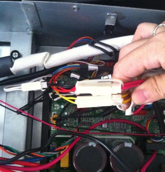
31 Indoor / outdoor units communication error Start: Power off, then Power on the A/C by the Breaker. (reconnect the power wire). Is it still displaying the error code? Check wiring on the outdoor and indoor terminal follow the wiring diagram. Is all connecting correctly? Reconnect the wiring Reconnect the wiring Turn on all indoor unit by remote controller. Is all indoor unit display Measure Vs, is it moving alternately between positive value and negative value? (Vs is the voltage between S and L2). Refer PIC 1 A: Is all the wiring between terminal and Indoor PCB connect ok? Change the Indoor PCB Turn off the all indoor units. Is IPM power LED or operating LED lamp On? Refer PIC2 change IPM Power on by remote controller, IIs it still displaying the error code after 3 minutes? Is main board lamp on? Refer PIC 3. Is the reactor connecting well? Reconnect the wiring Change Outdoor Main PCB Is indoor units number correct? Check on the outdoor check point. (2 for dual zone, 3 for tri zone, 4 for qua zone). Refer PIC 4. Trouble is solved first time second time A Change outdoor unit PCB assembly(include wiring) totally

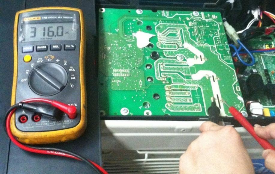
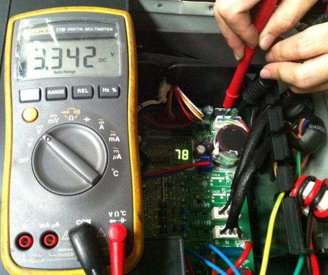
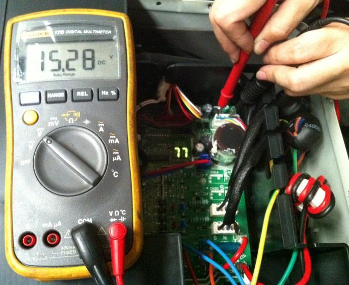
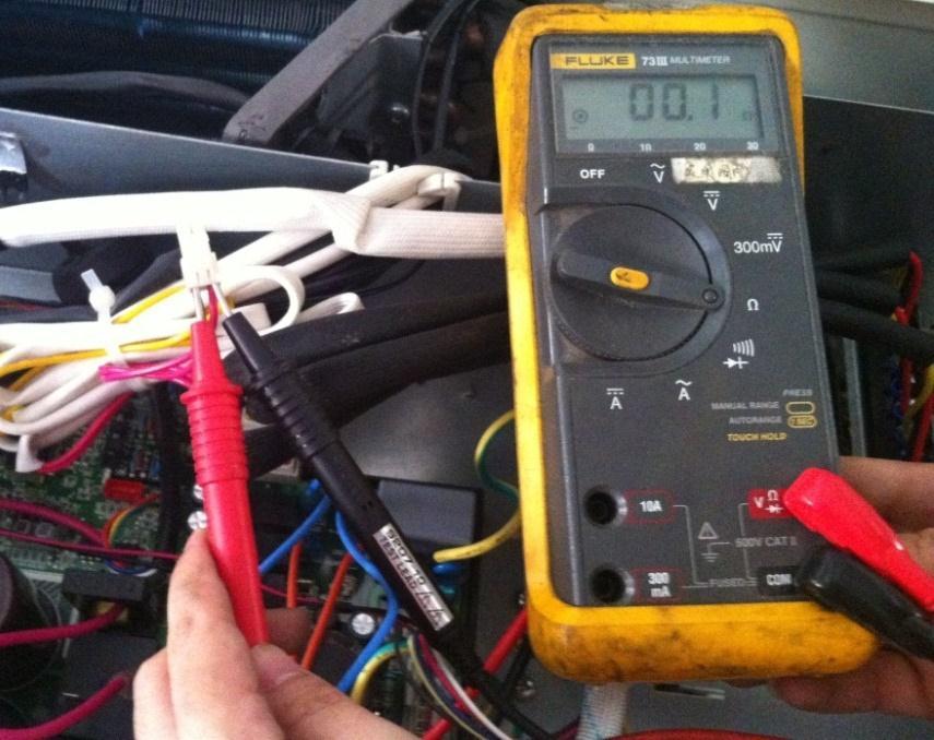
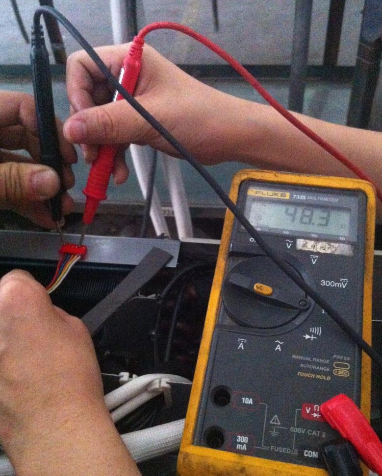
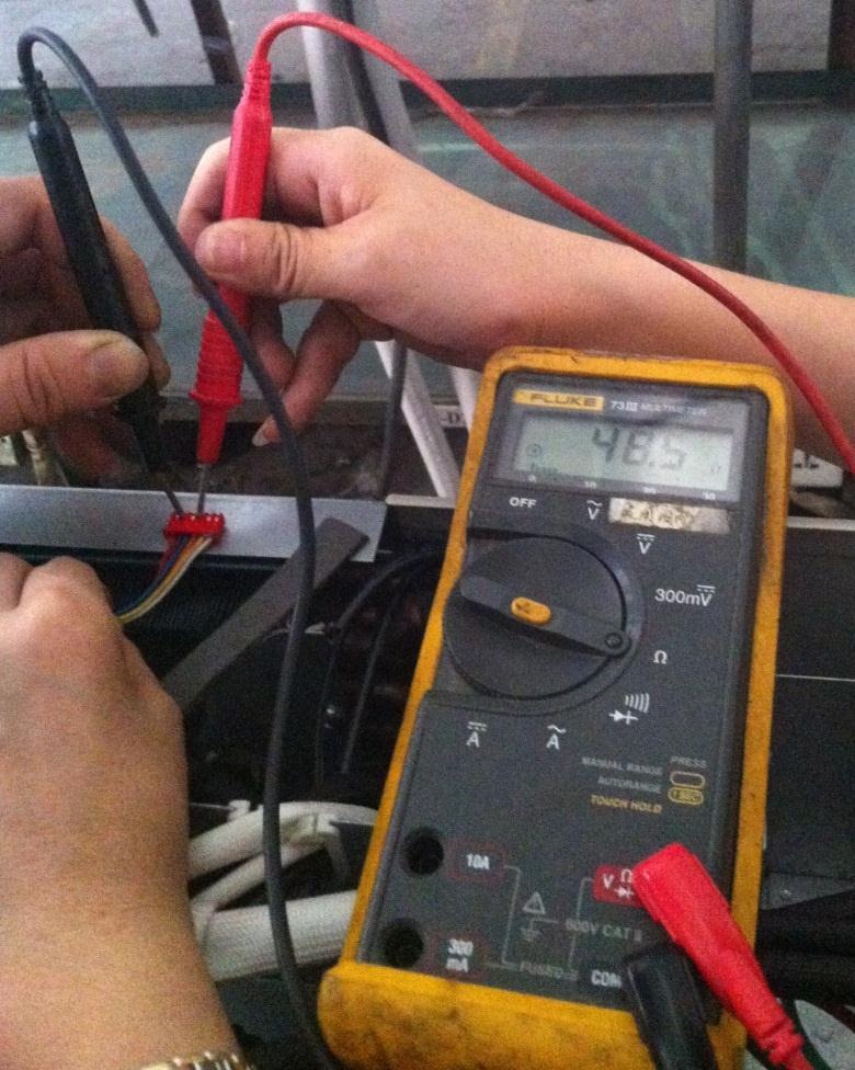
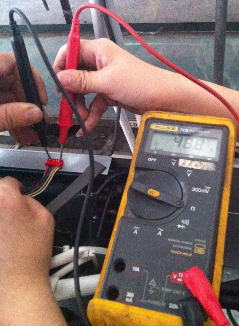
32 Pic 1: Use a multimeter to test the DC voltage between L2 port and S port of outdoor unit. The red pin of multimeter connects with L2 port while the black pin is for S port. When AC is normal running, the voltage will move alternately between positive value and negative value. Pic 2: IPM (for dual/tri/qua-zone) Power (some models) Self-Check OK Operating

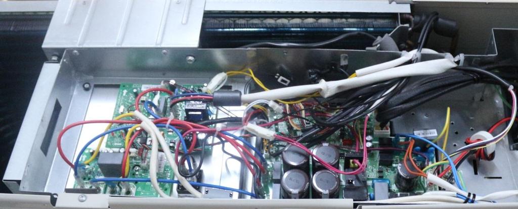
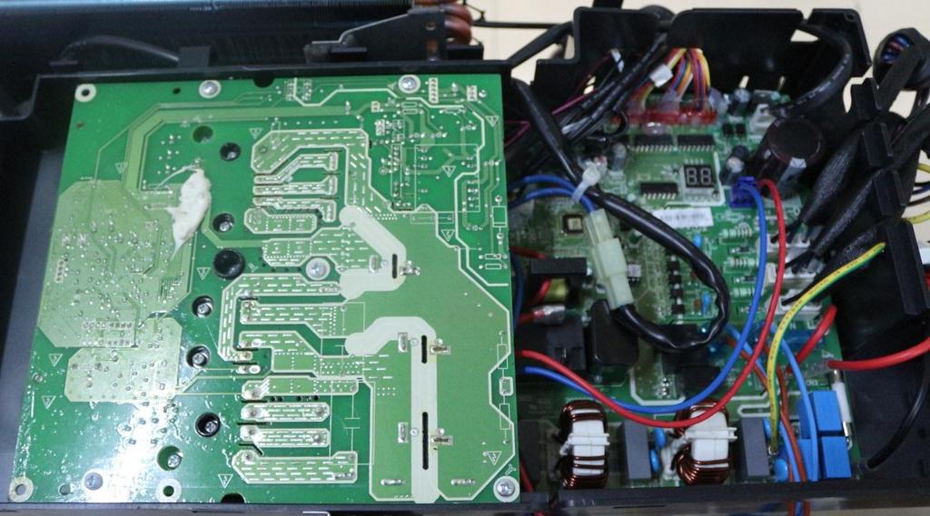
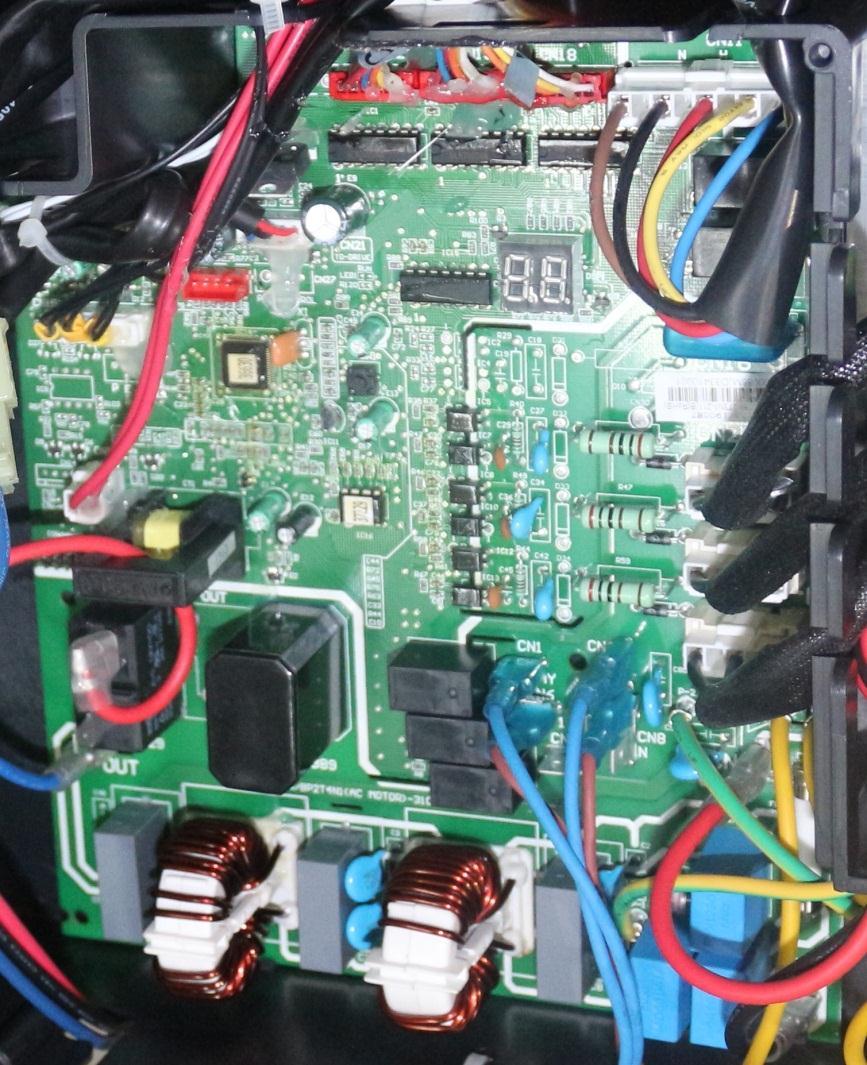
33 PIC3: Main board LED when power on and unit standby. PIC 4: Check point button, press 1 time for check how many indoor units are connected.
34 zero-crossing signal error diagnosis and solution. Malfunction decision conditions When PCB does not receive zero crossing signal feedback for 4 minutes or the zero crossing signal time interval is abnormal. Supposed causes Connection mistake PCB faulty Trouble shooting: Check if the connections and power supply is normal? Correct the connections. Turn on the unit when the power supply is good. Indoor main PCB is defective. Replace indoor main PCB.
35 Indoor fan speed has been out of control diagnosis and solution. Malfunction decision conditions When indoor fan speed keeps too low (300RPM) for certain time, the unit will stop and the LED will display the failure. Supposed causes Wiring mistake Fan ass y faulty Fan motor faulty PCB faulty Trouble shooting: Shut off the power supply and turn it on 1 minute later. Is it still displaying the error code? The unit operates normally. Shut off the power supply, rotate the fan by hand. Does it rotate properly? Find out the cause and have it solved. For example, check whether the fan is blocked or the bearing is broken? Check the wires of fan motor. Are all the connections good? Correct the connections. Check whether the fan motor is normal through index 1? Replace the fan motor If the malfunction is still existing, replace the main PCB Check whether the main PCB is normal through index 2? Replace the main PCB. The malfunction is solved?
36 Index 1: 1: Indoor AC fan motor Power on and set the unit running in fan mode at high fan speed. After running for 15 seconds, measure the voltage of pin1 and pin2. If the value of the voltage is less than 100V (208~240V power supply)or 50V(115V power supply), the PCB must have problems and need to be replaced. 2. Indoor DC fan motor (control chip is inside fan motor) Power on and when the unit is in standby, measure the voltage of pin1-pin3, pin4-pin3 in fan motor connector. If the value of the voltage is not in the range showing in below table, the PCB must have problems and need to be replaced. For other models: DC motor voltage input and output NO. Color Signal Voltage 1 Red Vs/Vm 200V~380V Black GND 0V 4 White Vcc V 5 Yellow Vsp 0~6.5V 6 Blue FG V
37 Open or short circuit of temperature sensor diagnosis and solution. Malfunction decision conditions If the sampling voltage is lower than 0.06V or higher than 4.94V, the LED will display the failure. Supposed causes Wiring mistake Sensor faulty PCB faulty Trouble shooting: Check the connections between temperature sensor and PCB. Are the connections good? Correct the connections. Check the resistance value of the sensor via Appendix 1 and Appendix 2 Is it normal? Replace indoor or outdoor PCB. Replace the sensor
38 IPM module or IGBT over-strong current protection diagnosis and solution. Malfunction decision conditions Supposed causes Trouble shooting: When the voltage signal that IPM send to compressor drive chip is abnormal, the display LED will show P6 and AC will turn off. Wiring mistake IPM malfunction Outdoor fan ass y faulty Compressor malfunction Outdoor PCB faulty
39 IPM module protection Check whether the voltage range of P-N on IPM module is normal? DC V for 18-27KBtu/h; DC V for 36KBtu/h Check whether the input power supply is correct? V, 1N, 60Hz Regulate it to correct, then check whether the system can work normally? Check whether the connecting line between main board and the IPM module is connected tightly Connect it tightly, check ok or not? Check whether the power supply line is connected correctly and tightly Connect it correctly and tightly, check ok or not? Check whether the connecting line of the compressor is connected correctly or tightly Connect it well, check ok or not? Check whether the lines in E-part box are connected tightly Connect it tightly, check ok or not? Replace the IPM module, check whether the system can work normally? Check if the outdoor fan runs properly or the outdoor unit ventilation is good. Replace the main board; check whether the system can work normally? For AC fan models, please refer to 9.4 Trouble Criterion Of Main Parts, check whether the resistance of the fan motor is normal. If not, replace the fan motor. For DC fan models, refer to the solution of fan speed has been out of control malfunction. Find out the cause and have it solved. Check whether the bridge rectifiers are normal? Use the multimeter to measure the resistance between each two terminals, check whether there is the condition that value of resistance is 0 Check whether the connecting line of every reactor s i normal? If the line is broken, the resistance of the two ports is (models except for KSIM40912-H216 (1st gen) & KSIM40912-H216 (2nd gen); Check whether the PFC module broken (for KSIM40912-H216 (1st gen) & KSIM40912-H216 (2nd gen)) Replace the bridge rectifiers Replace the connecting line or reactor or replace the PFC module (for KSIM40912-H216 (2nd gen)) Replace the compressor, check whether the system can work normally? Trouble is solved
40 Over voltage or too low voltage protection diagnosis and solution. Voltage protection Check the voltage of outdoor unit power supply, whether the voltage between L(L1) and N (L2) is about 187~253VAC Check the power supply Check whether the voltage of IPM board P and N is normal? DC V for 18-27KBtu/h; DC V for 36KBtu/h Replace bridge rectifiers, and then check whether the system can run normally(only for quazone) Replace IPM board, and then check whether the system can run normally Replace outdoor main board Trouble is solved
41 Temperature protection of compressor top diagnosis and solution. Malfunction decision conditions Supposed causes If the sampling voltage is not 5V, the LED will display the failure. Wiring mistake Over load protector faulty System block Outdoor PCB faulty Temperature protection of compressor top Whether compressor operates? Whether the connection is good? Reconnect and retest. Whether refrigerant circulation volume is normal? Whether protector is normal? If protector is normal,resistance = 0 Replace the protector. Charge refrigerant Whether abnormality is the same after gas charging? Replace the outdoor main PCB Check refrigerant system (such as clogging of capillary etc.) Inverter compressor drive error diagnosis and solution The trouble shooting is same with one of IPM module protection(p0).
42 Water-level alarm malfunction diagnosis and solution (For cassette / ducted) Malfunction decision conditions Supposed causes Power off, then restart the unit 3 minutes later. Is it still displaying the error code? If the sampling voltage is not 5V, the LED will display the failure. Wiring mistake Water-level switch faulty Water pump faulty Indoor PCB faulty If the water-level switch is inserted well? Insert the water-level switch well If the water-level switch is broken? Replace the water-level switch Replace the water pump, If malfunction is still not solved Replace the indoor main PCB
43 Mode conflict. Error Code Malfunction decision conditions Unit action P5 The indoor units cannot work cooling mode and heating at same time. Heating mode has a priority. Suppose Indoor unit A working in cooling mode or fan mode, and indoor unit B is set to heating mode, then A will change to off and B will work in heating mode. Suppose Indoor unit A working in heating mode, and indoor unit B is set to cooling mode or fan mode, then B will change to stand by and A will be no change. Cooling mode Heating Mode Fan Off Cooling mode Heating Mode Fan Off : mode conflict; : Mode conflict

44 8.4.2 Outdoor unit trouble shooting E0 (Outdoor EEPROM malfunction) error diagnosis and solution Error Code E0 Malfunction decision conditions Supposed causes Trouble shooting: PCB main chip does not receive feedback from EEPROM chip Installation mistake PCB faulty Outdoor EEPROM malfunction Power off, then restart the unit 3 minutes later Replace the outdoor main PCB EEPROM: a read-only memory whose contents can be erased and reprogrammed using a pulsed voltage. For the location of EEPROM chip, please refer to the below photos. Outdoor PCB (KSIM330-H219)
45 E2(Communication malfunction between indoor and outdoor units) error diagnosis and solution. Error Code E2 Malfunction decision conditions Supposed causes Indoor unit does not receive the feedback from outdoor unit during 120 seconds or outdoor unit does not receive the feedback from any one indoor unit during 180 seconds. Wiring mistake Indoor or outdoor PCB faulty Trouble shooting:
46 Communication malfunction between indoor and outdoor units Start: Power off, then Power on the A/C by the Breaker. (reconnect the power wire). Is it still displaying the error code? Check wiring on the outdoor and indoor terminal follow the wiring diagram. Is all connecting correctly? Reconnect the wiring Reconnect the wiring Turn on all indoor unit by remote controller. Is all indoor unit display Measure Vs, is it moving alternately between positive value and negative value? (Vs is the voltage between S and L2). Refer PIC 1 A: Is all the wiring between terminal and Indoor PCB connect ok? Change the Indoor PCB Turn off the all indoor units. Is IPM power LED or operating LED lamp On? Refer PIC2 change IPM Power on by remote controller, IIs it still displaying the error code after 3 minutes? Is main board lamp on? Refer PIC 3. Is the reactor connecting well? Reconnect the wiring Change Outdoor Main PCB Is indoor units number correct? Check on the outdoor check point. (2 for dual zone, 3 for tri zone, 4 for qua zone). Refer PIC 4. Trouble is solved first time second time A Change outdoor unit PCB assembly(include wiring) totally
47 Pic 1: Use a multimeter to test the DC voltage between L2 port and S port of outdoor unit. The red pin of multimeter connects with L2 port while the black pin is for S port. When AC is normal running, the voltage will move alternately between positive value and negative value. Pic 2: IPM (For dual/tri-zone) Operating Self-Check

48 Pic 2: IPM (For qua-zone) Power, Self-Check Operating PIC3: Main board LED when power on and unit standby. PIC 4: Check point button, press 1 time for check how many indoor units are connected.
49 E3 (Communication malfunction between IPM board and outdoor main board) error diagnosis Error Code E3 Malfunction decision conditions Supposed causes Trouble shooting: PCB main chip does not receive feedback from IPM module during 60 seconds. Wiring mistake PCB faulty Communication malfunction between IPM board and outdoor main board Is there at least one LED in the IPM board light? Check the signal wire between the IPM module and the main board, is it connected good? Reconnect and retry. Is error still display? Replace IPM board, and then check whether the system can run normally Replace outdoor main board, and then check whether the system can run normally Replace the electric control box Trouble is solved


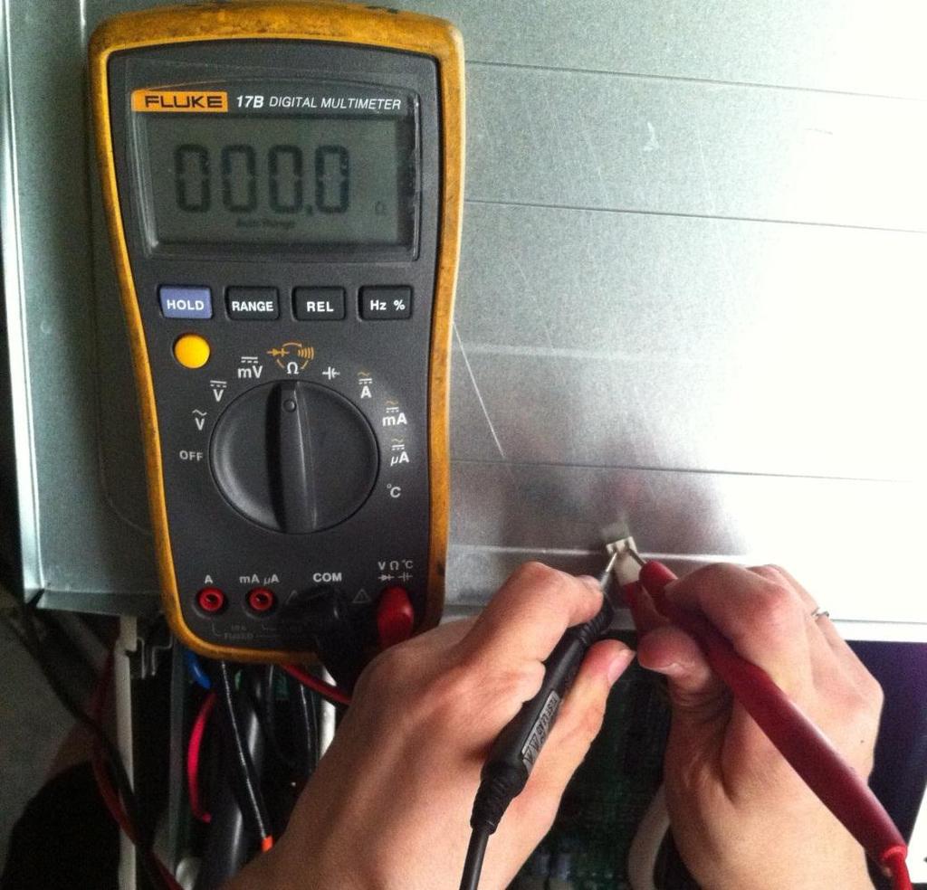
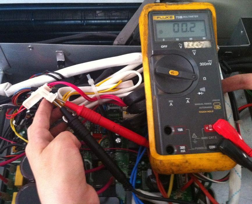
50 Remark: Use a multimeter to test the DC voltage between black pin and white pin of signal wire The normal value should be around 5V. Use a multimeter to test the DC voltage between black pin and red pin of signal wire. The normal value should be around 12V.

51 E4(open or short circuit of outdoor temperature sensor) diagnosis and solution F1/F2/F3/F4/F5 (open or short circuit of indoor coil temperature sensor) diagnosis and solution.. Error Code E4/F1/F2/F3/F4/F5 Malfunction decision conditions Supposed causes If the sampling voltage is lower than 0.06V or higher than 4.94V, the LED will display the failure. Wiring mistake Sensor faulty PCB faulty Trouble shooting: Check the connections between temperature sensor and PCB. Are the connections good? Correct the connections. Check the resistance value of the sensor via Appendix 1 and Appendix 2 Is it normal? Replace indoor or outdoor PCB. Replace the sensor
52 E5 (Voltage protection) error diagnosis and solution. Error Code Malfunction decision conditions Supposed causes Trouble shooting: E5 An abnormal voltage rise or drop is detected by checking the specified voltage detection circuit. Power supply problems. System leakage or block PCB faulty Voltage protection Check the voltage of outdoor unit power supply, whether the voltage between L(L1) and N (L2) is about 187~253VAC Check the power supply Check whether the voltage of IPM board P and N is normal? DC V for 18-27KBtu/h; DC V for 36KBtu/h Replace bridge rectifiers, and then check whether the system can run normally(only for quazone) Replace IPM board, and then check whether the system can run normally Replace outdoor main board Trouble is solved
53 IPM (for dual/trizone) IPM (for quazone) P-N (for dual/tri-zone)
")
54 P-N (for qua-zone)
 qua-zone)")
55 bridge rectifier (for dual/tri-zone) bridge rectifier (for qua-zone)

56 Remark: Measure the DC voltage between + and - port. The normal value should be 190V~250V.
57 E8 (Outdoor fan speed has been out of control) diagnosis and solution Error Code E8 Malfunction decision conditions Supposed causes Trouble shooting: When outdoor fan speed keeps too low (300RPM) or too high(2400rpm) for certain time, the unit will stop and the LED will display the failure. Wiring mistake Fan ass y faulty Fan motor faulty PCB faulty Power off, then restart the unit 3 minutes later. Is it still displaying the error code? The unit operates normally. Shut off the power supply, rotate the fan by hand. Does it rotate properly? Find out the cause and have it solved. For example, whether the fan is blocked or the screws which fix the fan are tighten. Check the wiring of fan motor. Are all the connections good? Correct the connections. Check whether the main PCB is normal through index 1? Replace the main PCB Replace the fan motor Index 1:


58 1. DC fan motor(control chip is inside fan motor) Power on and when the unit is in standby, measure the voltage of pin1-pin3, pin4-pin3 in fan motor connector. If the value of the voltage is not in the range showing in below table, the PCB must have problems and need to be replaced. DC motor voltage input and output NO. Color Signal Voltage 1 Red Vs/Vm 200~380V Black GND 0V 4 White Vcc 13.5~16.5V 5 Yellow Vsp 0~6.5V 6 Blue FG 13.5~16.5V Vs Vcc Vsp FG
59
60 P0 (Temperature protection of compressor top) error diagnosis and solution. Error Code Malfunction decision conditions Supposed causes Trouble shooting: P0 If the sampling voltage is not 5V, the LED will display the failure. Wiring mistake Over load protector faulty System block Outdoor PCB faulty Temperature protection of compressor top Check the air flow system of indoor and outdoor units Clear up the air inlet and outlet or the heat exchanger of indoor and outdoor units. Power off, then restart the unit 10 minutes later Check whether the temperature of compressor top is more than 100 Check wiring connection of the overload protector Correct the connection. Check the refrigerant volume charge Measure the resistance between the two ports of the OLP. Is it zero? Replace the OLP. Replace the outdoor main PCB. Refrigerant system is blocked, such as capillary or welded point of pipes. Recharge the correct refrigerant volume.
61
62 P1 (High pressure protection) error diagnosis and solution. Error Code Malfunction decision conditions Supposed causes Trouble shooting: P1 If the sampling voltage is not 5V, the LED will display the failure. Wiring mistake Over load protector faulty System block Outdoor PCB faulty
63 High pressure protection Whether the wiring between the high pressure switch and main control board is connected well or correctly Connect it well Whether the high pressure protector is broken Method: Disconnect the plug. Measure the resistance of the high pressure protector, if the protector is normal the value is o, Replace high pressure protector Check whether the outdoor ambient temperature is higher than 122ºF (50ºC) Stop the unit Check if the outdoor unit ventilation is good NO Make the outdoor unit ventilate well Check if the outdoor fan runs properly please refer to the solution of fan speed has been out of control malfunction. Find out the cause and have it solved. Check whether the heat exchanger is dirty Clean the heat exchanger Replace outdoor main board Check whether the refrigerant system is ok
64
65 P2 (Low pressure protection) error diagnosis and solution. Error Code Malfunction decision conditions Supposed causes Trouble shooting: P2 If the sampling voltage is not 5V, the LED will display the failure. Wiring mistake Over load protector faulty System block Outdoor PCB faulty
66 Low pressure protection Whether the wiring between the low pressure protector and main control board is connected well or correctly Connect it well Whether the low pressure protector is broken Method: Disconnect the plug. Measure the resistance of the low pressure protector. If the protector is normal the value is o Replace low pressure protector Check whether the outdoor ambient temperature is too low Stop the unit Check whether valve core of high pressure valve is opened Check if if the indoor fan runs properly in cooling mode Open fully valve core of high pressure valve please refer to the solution of fan speed has been out of control malfunction. Find out the cause and have it solved. Replace outdoor main board Refrigerant is not enough add the refrigerant Check whether the refrigerant system is ok
67
68 P3 (Current protection of compressor) error diagnosis and solution. Error Code Malfunction decision conditions Supposed causes Trouble shooting: P3 If the outdoor current exceeds the current limit value, the LED will display the failure. Wiring mistake Over load protector faulty System block Outdoor PCB faulty Current protection of compressor Judge 1: Check whether the input current of the power supply wire is more than 12.5A(18K) (For 27K, it is 17.For 30K, it is 18.5.For 36K, it is 23A) Replace outdoor main board Check whether the refrigerant system is ok Judgege 2: Check whether the outdoor ambient temperature is higher than 122ºF Stop the unit Judge 3: Check whether the outdoor unit is bad ventilation Make the outdoor unit ventilate well Judge 4: Check whether the heat exchanger is dirty Clean the heat exchanger Judge 5: The refrigerant pipe is blocked Let the refrigerant out, then use the high pressure nitrogen or refrigerant to blow pipe, vacuumize and charge the refrigerant again Replace outdoor main board,and check whether the system can run normally Replace the electric control box Trouble is solved
69
70 P4 (Temperature protection of compressor discharge) error diagnosis and solution. Error Code Malfunction decision conditions Supposed causes Trouble shooting: P4 When the compressor discharge temperature(t5) is more than 239ºF (115ºC) for 10 seconds, the compressor will stop andrestart till T5 is less than 194ºF (90ºC). Refrigerant leakage Wiring mistake The discharge temperature sensor faulty Outdoor PCB faulty Temperature protection of compressor discharge Check whether the compresor discharge temp. is more than 239ºF (115ºC)? Check whether the refrigerant is leak Stop leaking and add refrigerant Check whether the connection is right between compressor discharge temp. sensor and PCB according to wiring diagrams? Correct the wiring connection Measure the resistance value of compressor discharge temp. sensor. If the value is not normal is normal refer to the Appendix 2? Replace the compressor discharge temp. sensor Replace outdoor main PCB Replace high pressure valve assy
71 P5 (High temperature protection of condenser) error diagnosis and solution. Error Code Malfunction decision conditions Supposed causes Trouble shooting: P5 When outdoor pipe temperature is more than 149ºF (65 C), the unit will stop, and unit runs again when outdoor pipe temperature is less than 126ºF (52 C). The condenser temperature sensor faulty Heat exchanger dirty System block High temperature protection of condenser Check the connection between temperature sensor and PCB. Correct the connection Check whether the condenser temperature is Higher than 149ºF (65ºC) Check whether the resistance of condenser temp. sensor is normal refer to the Appendix 1 Replace the temperature sensor Check whether the otdoor ambient temperature is higher than 122ºF (50ºC) Stop the unit Check if the outdoor unit ventilation is good Make the outdoor unit ventilate well Check if the outdoor fan runs properly please refer to the solution of fan speed has been out of control malfunction. Find out the cause and have it solved. Check whether the heat exchanger is dirty Clean the heat exchanger Replace outdoor main board Refrigerant is not enough add the refrigerant Check whether the refrigerant system is ok
72 P6 (IPM module protection) error diagnosis and solution. Error Code Malfunction decision conditions Supposed causes Trouble shooting: P6 When the voltage signal that IPM send to compressor drive chip is abnormal, the display LED will show P6 and AC will turn off. Wiring mistake IPM malfunction Outdoor fan ass y faulty Compressor malfunction Outdoor PCB faulty
73 IPM module protection Check whether the voltage range of P-N on IPM module is normal? DC V for 18-27KBtu/h; DC V for 36KBtu/h Check whether the input power supply is correct? V, 1N, 60Hz Regulate it to correct, then check whether the system can work normally? Check whether the connecting line between main board and the IPM module is connected tightly Connect it tightly, check ok or not? Check whether the power supply line is connected correctly and tightly Connect it correctly and tightly, check ok or not? Check whether the connecting line of the compressor is connected correctly or tightly Connect it well, check ok or not? Check whether the lines in E-part box are connected tightly Connect it tightly, check ok or not? Replace the IPM module, check whether the system can work normally? Check if the outdoor fan runs properly or the outdoor unit ventilation is good. For KSIM30912-H216 (2nd gen), please refer to 8.5 Trouble Criterion Of Main Parts, check whether the resistance of the fan motor is normal. If not, replace the fan motor. For other models, refer to the solution of fan speed has been out of control malfunction. Find out the cause and have it solved. Check whether the bridge rectifiers are normal? Use the multimeter to measure the resistance between each two terminals, check whether there is the condition that value of resistance is 0 Check whether the connecting line of every reactor is normal? If the line is broken, the resistance of the two ports is (models except for KSIM H216 (2nd gen));check whether the PFC module broken (for KSIM H216 (2nd gen)) Replace the bridge rectifiers Replace the main board; check whether the system can work normally? Replace the connecting line or reactor or replace the PFC module (for KSIM40912-H216 (2nd gen)) Replace the compressor, check whether the system can work normally? Trouble is solved


74 The cooling operation or heating operation does not operate. Supposed causes 4-way valve faulty Check of 4-way, please refer to part 5 in 9.5 Trouble Criterion Of Main Parts When cooling, heat exchanger of non-operating indoor unit frosts. When heating, non-operating indoor unit get warm. Supposed causes EXV faulty Wire and tubing connected in reverse. Check of EXV, please refer to part 6 in 9.5 Trouble Criterion Of Main Parts. tice: If you replace outdoor main PCB of KSIM30912-H216 (2nd gen), you need to check whether the PCB is produced before Apr If yes, you need to short connect OLP connector., Otherwise, the outdoor LED will show P0.
75 8.5 Trouble Criterion Of Main Parts. Spec. Indoor unit Model KSIE009-H221-I KSIE012-H220-I KSIE018-H220-I KSIE024-H220-I Indoor fan motor WZDK20-38G WZDK20-38G WZDK58-38G WZDK60-38G Model KDIR09-H2 KDIR12-H2 KDIR18-H2 KDIR24-H2 Indoor fan motor WZDK55-38GS-W WZDK55-38GS-W WZDK90-38GS-W WZDK90-38GS-W Model KDIR09-H2 KDIR12-H2 KDIR18-H2 Indoor fan motor WZDK46-38G WZDK46-38G WZDK46-38G
76 1. 1.Temperature sensor checking Disconnect the temperature sensor from PCB, measure the resistance value with a tester. Temperature Sensors. Room temp.(t1) sensor, Indoor coil temp.(t2) sensor, Outdoor coil temp.(t3) sensor, Outdoor ambient temp.(t4) sensor, Compressor discharge temp.(t5) sensor. Measure the resistance value of each winding by using the multi-meter.
77 Appendix 1 Temperature Sensor Resistance Value Table (ºC-K) ºF K Ohm ºF K Ohm ºF K Ohm ºF K Ohm
78 Appendix Unit: ºF-K Discharge temp. sensor table B(25/50)=3950K R(90 )=5KΩ±3%

79 Appendix 3: Compressor check Measure the resistance value of each winding by using the tester. Position Blue - Red Resistance Value ATM150D23UFZ ATF235D22UMT ATF250D22UMT ATF310D43UMT ATQ360D1UMU ATQ420D1UMU 1.72 Ω 0.75 Ω 0.75 Ω 0.65 Ω 0.37 Ω 0.38Ω
80 3. IPM continuity check Turn off the power, let the large capacity electrolytic capacitors discharge completely, and dismount the IPM. Use a digital tester to measure the resistance between P and UVWN; UVW and N. (+)Red P Digital tester (-)Black N U V W rmal resistance value (Several MΩ) (+)Red U V W (+)Red Digital tester (-)Black N rmal resistance value (Several MΩ) 4. AC Fan Motor. Measure the resistance value of each winding by using the tester. Position Resistance Value RPG20B RPG28H Black - Red 381Ω±8% (68ºF) 342Ω±8% (68ºF) 183.6Ω±8% (68ºF) 180Ω±8% (68ºF) (Brand: Weiling) (Brand: Dayang) (Brand: Weiling) (Brand: Wolong) White - Black 267Ω±8% (68ºF) 253Ω±8% (68ºF) 206Ω±8% (68ºF) 190Ω±8% (68ºF) (Brand: Weiling) (Brand: Dayang) (Brand: Weiling) (Brand: Wolong) Measure the resistance value of each winding by using the tester.
 317Ω±8% (68 ºF - 20 ºC) 145Ω±8% (68 ºF - 20 ºC) 345Ω±8% (68 ºF - 20 ºC) 627Ω±8% (68 ºF - 20 ºC) 88.")
 (68 ºF - 20 ºC) (68 ºF - 20 ºC) (68 ºF - 20 ºC) (68 ºF - 20 ºC) (68 ºF - 20 ºC) (68 ºF - 20 ºC) 76Ω±8% 19Ω±8% 252Ω±8% 88Ω±8% 150Ω±8% 374.")
81 Position Resistance Value YDK70-6FB YDK180-8GB YSK27-4G YSK68-4B YDK45-6B YSK25-6L YDK53-6FB(B) Black - Red 56Ω±8% (68 ºF - 20 ºC) 24.5Ω±8% (68 ºF - 20 ºC) 317Ω±8% (68 ºF - 20 ºC) 145Ω±8% (68 ºF - 20 ºC) 345Ω±8% (68 ºF - 20 ºC) 627Ω±8% (68 ºF - 20 ºC) 88.5Ω±8% (68 ºF - 20 ºC) Red - Yellow Yellow - Blue 76Ω±8% 19Ω±8% 252Ω±8% 88Ω±8% 150Ω±8% 374.3Ω±8% 138Ω±8% (68 ºF - 20 ºC) (68 ºF - 20 ºC) (68 ºF - 20 ºC) (68 ºF - 20 ºC) (68 ºF - 20 ºC) (68 ºF - 20 ºC) (68 ºF - 20 ºC) 76Ω±8% 19Ω±8% 252Ω±8% 88Ω±8% 150Ω±8% 374.3Ω±8% 138Ω±8% (68 ºF - 20 ºC) (68 ºF - 20 ºC) (68 ºF - 20 ºC) (68 ºF - 20 ºC) (68 ºF - 20 ºC) (68 ºF - 20 ºC) (68 ºF - 20 ºC) 5.4-way valve 1. Power on, use a digital tester to measure the voltage, when the unit operates in cooling, it is 0V. When the unit operates in heating, it is about 230VAC. If the value of the voltage is not in the range, the PCB must have problems and need to be replaced. 2 Turn off the power, use a digital tester to measure the resistance. The value should be 1.8~2.5 KΩ.

82 6.EXV check Disconnect the connectors.


83 Resistance to EXV coil Color of lead wire rmal Value Red- Blue Red - Yellow Brown-Orange About 50Ω Brown-White

84 Red- Blue Red - Yellow
85 Brown-Orange Brown-White
Multi zone. MULTI OUTDOOR UNITsS. CONDENsSING UNITsS. Revision V1.0: Table of Contents
 MULTI OUTDOOR UNITsS sservice MANUAL Multi zone CONDENsSING UNITsS Revision V1.0: 20160616 Table of Contents 1. Indoor Unit Combination 2. Suggested Indoor Unit Model Numbers 3. Dimension Of Outdoor Unit
Multi zone Two, Three, Four and Five Zones
 MULTI SPLIT SYSTEM OUTDOOR UNITS SERVICE MANUAL Multi zone Two, Three, Four and Five Zones DC INVERTER MULTI ZONE OUTDOOR UNITS Revision A: ODMI E 1601 PDB55/2016 Model Numbers: YN020GMFI22M2D YN030GMFI22M3D
SUPER DC INVERTER MULTI TYPE INSTRUKCJA SERWISOWA
 ODMFI-B-1211 INSTRUKCJA SERWISOWA SUPER DC INVERTER MULTI TYPE K2OD-14HFN1-Q, K2OD-18HFN1-Q, K3OD-21HFN1-Q K3OD-27HFN1-Q, K4OD-28HFN1-Q, K4OA-36HFN1-Q K5OC-36HFN1-Q DC MULTI OUTDOOR UNITS CONTENTS 1. General
FROZEN SERIE SERVICE MANUAL. DC Inverter R32. Sistemi per la climatizzazione
 DC Inverter R32 Sistemi per la climatizzazione SERVICE MANUAL FROZEN SERIE CONTENTS 1. General information of Outdoor Units... 3 2. Features... 4 3. Dimensions... 5 4. Refrigeration Cycle Diagram... 6
SERVICE MANUAL Room Air Conditioner DC Inverter Multi Split Outdoor units
 SERVICE MANUAL Room Air Conditioner DC Inverter Multi Split Outdoor units FS2MIF-140AE2 FS2MIF-180AE2 FS3MIF-210AE2 FS3MIF-270AE2 FS4MIF-280AE2 FS4MIF-360AE2 FS5MIF-360AE2 NOTE: Before servicing the unit,
MULTI INVERTER SERIE H6M
 MULTI INVERTER SERIE H6M Service manual www.mundoclima.com Thank you very much for purchasing our products. Please read this manual carefully before installing and using the unit. ODMFI-B1-1606 CL20440
YN-M SERIES MULTI SPLIT SYSTEM MULTI CIRCUIT OUTDOOR UNITS (2, 3 AND 4 ZONES) SERVICE MANUAL PRE 2014 MODELS (Pre Serials) CONDENSING UNITS
 SERVICE MANUAL PRE 2014 MODELS (Pre Serials) CONDENSING UNITS") YN-M SERIES MULTI SPLIT SYSTEM MULTI CIRCUIT OUTDOOR UNITS (2, 3 AND 4 ZONES) SERVICE MANUAL PRE 2014 MODELS (Pre 50130047 Serials) CONDENSING UNITS Parker Davis HVAC International, Inc. Revision B: ODMI
YN-M SERIES MULTI SPLIT SYSTEM MULTI CIRCUIT OUTDOOR UNITS (2, 3 AND 4 ZONES) SERVICE MANUAL PRE 2014 MODELS (Pre 50130047 Serials) CONDENSING UNITS Parker Davis HVAC International, Inc. Revision B: ODMI
Service Manual AIR CONDITIONER
 Service Manual AIR CONDITIONER DC INVERTER MULTI TYPE This manual applies to models: High Wall Duct Cassette Console Universal CDU 42QHF009DS 42QHF012DS 42QHF018DS 42QSM009DS 42QSM012DS 42QSM018DS 42QTD009DS
SERVICE MANUAL 42QHF009DS* 42QHF012DS* 42QHF018DS* 42QHF022DS* 38QUS009DS* 38QUS012DS* 38QUS018DS* 38QUS022DS* Indoor unit.
 SERVICE MANUAL Indoor unit Outdoor unit 42QHF009DS* 42QHF012DS* 42QHF018DS* 42QHF022DS* 38QUS009DS* 38QUS012DS* 38QUS018DS* 38QUS022DS* INDEX PART1 GENERAL INFORMATION PART2 ELECTRICAL DIAGRAM PART3 TROUBLE
TROUBLESHOOTING TROUBLESHOOTING. Indoor unit EEPROM parameter error. Indoor / outdoor units communication error. Zero-crossing signal detection error
 www.olmo-comfort.com TROUBLESHOOTING When below list for identification of error code occurs, please turn off air conditioner and disconnect power, and then contact the qualified professionals for service.
DuctlessAire ES Series. Service Manual 2016 ABSSA-B4-1601
 DuctlessAire ES Series Service Manual 2016 ABSSA-B4-1601 CONTENTS 1. Precaution... 1 1.1 Safety Precaution... 1 1.2 Warning... 1 2. Model list... 4 3. Dimension... 5 3.1 Indoor Unit... 5 3.2 Outdoor Unit...
YC ON-OFF SERIES. Service Manual
 YC ON-OFF SERIES Service Manual CONTENTS 1. Precaution... 3 1.1 Safety Precaution... 3 1.2 Warning... 3 2. Model Lists... 6 3. Dimension... 7 3.1 Indoor Unit... 7 3.2 Outdoor Unit... 11 4. Refrigerant
Light Commercial SUPER INVERTER SERIES MULTI TYPE
 Light Commercial SUPER INVERTER SERIES MULTI TYPE Service Manual 2017 CONTENTS 1. General information of Indoor Units... 1 2. Features... 2 3. Dimensions... 12 4. Service Space (unit: mm)... 19 5. Wiring
SERVICE MANUAL K LIGHT COMMERCIAL
 SERVICE MANUAL 36 48 60K LIGHT COMMERCIAL Cassette indoor unit Under-ceiling indoor unit Ducted indoor unit 42QTD036DS* 42QTD048DS* 42QTD060DS* 42QZL036DS* 42QZL048DS* 42QZL060DS* 42QSM036DS* 42QSM048DS*
HABITAT USER MANUAL TIN310**V33 TIN414**V33 TIN520**V33 TIN625**V33 TIN1036H2V02 TIN1939H2V02 INVERTER MINI SPLIT
 HABITAT INVERTER MINI SPLIT USER MANUAL TIN310**V33 TIN414**V33 TIN520**V33 TIN625**V33 TIN1036H2V02 TIN1939H2V02 WARNING The information contained in the manual is intended for use by a qualified service
Mission 3D Inverter Series
 Mission 3D Inverter Series Service Manual 2014 MBSEU-A-1412 CONTENTS 1. Precaution... 3 1.1 Safety Precaution... 3 1.2 Warning... 3 2. Function... 6 3. Dimension... 7 3.1 Indoor Unit... 7 3.2 Outdoor Unit...
Service Manual for TAS-18EHN, TAS-24EHN
 Service Manual for TAS-18EHN, TAS-24EHN CONTENTS 1. Precaution... 3 1.1 Safety Precaution... 3 1.2 Warning... 3 2. Function... 7 3. Dimension... 8 3.1 Indoor Unit... 8 3.2 Outdoor Unit... 10 4. Refrigerant
Dream Inverter Series. Service Manual 2017
 Dream Inverter Series Service Manual 2017 CONTENTS 1. Precaution... 3 1.1 Safety Precaution... 3 1.2 Warning... 3 2. Model List... 6 3. Dimension... 7 3.1 Indoor Unit... 7 3.2 Outdoor Unit... 11 4.Refrigerant
SERVICE MANUAL. Room Air Conditioner Split Wall-Mounted Type
 SERVICE MANUAL Room Air Conditioner Split Wall-Mounted Type FSAIF-Pro-95AE2 / FSOAIF-Pro-95AE2 FSAIF-Pro-125AE2 / FSOAIF-Pro-125AE2 FSAIF-Pro-185AE2 / FSOAIF-Pro-185AE2 FSAIF-Pro-245AE2 / FSOAIF-Pro-245AE2
F SERIES ON-OFF SERIES. Service Manual 2016
 F SERIES ON-OFF SERIES Service Manual 2016 CONTENTS 1. Precaution... 3 1.1 Safety Precaution... 3 1.2 Warning... 3 2. Function... 6 3. Dimension... 7 3.1 Indoor Unit... 7 3.2 Outdoor Unit... 9 4. Refrigerant
15C Inverter Series. Service Manual
 15C Inverter Series Service Manual CONTENTS 1. Precaution... 1 1.1 Safety Precaution... 1 1.2 Warning... 1 2. Function... 4 3. Dimension... 5 3.1 Indoor Unit... 5 3.2 Outdoor Unit... 7 4. Wiring Diagram...
SERVICE MANUAL SPLIT WALL-MOUNTED TYPE MODELS MWCOHC30S/MRCOHC30AS MWCOHC36S/MRCOHC36AS
 SERVICE MANUAL SPLIT WALL-MOUNTED TYPE MODELS MWCOHC30S/MRCOHC30AS MWCOHC36S/MRCOHC36AS CONTENTS 1. Precaution... 1 1.1 Safety Precaution... 1 1.2 Warning... 1 2. Function... 6 3. Dimension... 7 3.1 Indoor
Westinghouse. Split System Inverter Series. Service Manual
 Westinghouse Split System Inverter Series Service Manual Model: WIWPK/WCHPK Range: 2.6kw 7.6kw CONTENTS 1. Precaution... 1 1.1 Safety Precaution... 1 1.2 Warning... 1 2. Function... 5 3. Dimension... 6
SERVICE MANUAL. Room Air Conditioner Split Wall-Mounted Type
 SERVICE MANUAL Room Air Conditioner Split Wall-Mounted Type FSAIF-Pro-94AE2 / FSOAIF-Pro-94AE2 FSAIF-Pro-124AE2 / FSOAIF-Pro-124AE2 FSAIF-Pro-184AE2 / FSOAIF-Pro-184AE2 FSAIF-Pro-244AE2 / FSOAIF-Pro-244AE2
Vertu Plus 3D Inverter Series
 Vertu Plus 3D Inverter Series Service Manual 2015 VPSFI -A-1511 CONTENTS 1. Precaution... 3 1.1 Safety Precaution... 3 1.2 Warning... 3 2. Function... 6 3. Dimension... 7 3.1 Indoor Unit... 7 3.2 Outdoor
Bosch Split-Type Ductless Air Conditioner / Heat Pump
 Bosch Split-Type Ductless Air Conditioner / Heat Pump Climate 5000 AA Series Service Manual 2 Bosch Climate 5000 AA Series Split Type Ductless Air Conditioner / Heat Pump Service Manual Data subject to
LUNA INVERTER SERIES. Service Manual ASI-A-1301
 LUNA INVERTER SERIES Service Manual 2013 9ASI-A-1301 CONTENTS 1. Precaution... 3 1.1 Safety Precaution... 3 1.2 Warning... 3 2. Function... 7 3. Dimension... 8 3.1 Indoor Unit... 8 3.2 Outdoor Unit...
KSIM20912-H216 KSIM30912-H216 KSIM40912-H216
 SERVICE MANUAL KLIMAIRE AIRCONDITIONER KSIM DC INVERTER MULTI TYPE KSIM20912-H216 KSIM30912-H216 KSIM40912-H216 DC MULTI OUTDOOR UNITS CONTENTS 1. General information of Outdoor Units...3 2 Features...4
INVERTER SERIE H6 Service manual
 INVERTER SERIE H6 Service manual MUPR-H6 www.mundoclima.com Thank you very much for purchasing our products. Please read this manual carefully before installing and using the unit. AESFI-A-1509 CL20015
INSTRUKCJA SERWISOWA 12F INVERTER SERIES. Service Manual FSI-A-1310
 INSTRUKCJA SERWISOWA 12F INVERTER SERIES Service Manual 2013 12FSI-A-1310 CONTENTS 1. Precaution... 3 1.1 Safety Precaution... 3 1.2 Warning... 3 2. Function... 7 3. Dimension... 8 3.1 Indoor Unit... 8
NORTH AMERICAN HVAC PRODUCTS LTD 3208 BETA AVE, BURNABY BC V5G 4K4 CSNA-1305-A SERVICE MANUAL AIR CONDITIONER SPLIT WALL-MOUNTED TYPE.
 NORTH AMERICAN HVAC PRODUCTS LTD 3208 BETA AVE, BURNABY BC V5G 4K4 CSNA-1305-A SERVICE MANUAL AIR CONDITIONER SPLIT WALL-MOUNTED TYPE Corona Series CONTENTS 1. Precaution... 1 1.1 Safety Precaution...
Service Manual CAUTION ! WARNING SAFETY CONSIDERATIONS INTRODUCTION. 38MA*R Outdoor Unit Single Zone Ductless System Sizes 09 to 36
 38MA*R Outdoor Unit Single Zone Ductless System Sizes 09 to 36 Service Manual TABLE OF CONTENTS PAGE SAFETY CONSIDERATIONS... 1 INTRODUCTION... 1 MODEL / SERIAL NUMBER NOMENCLATURES... 2 SPECIFICATIONS...
KSIN INVERTER SERIES Service Manual 2013
 KSIN INVERTER SERIES Service Manual 2013 CONTENTS 1. Precaution............ 1 1.1 Safety Precaution... 1 1.2 Warning... 1 2. Function............ 6 3. Dimension............ 8 3.1 Indoor Units... 8 3.2
Installation, Operation & Maintenance
 Installation, Operation & Maintenance Contura 5G Series R410a High Ambient & High Efficiency MS-SVX041A-EN 1 Contents 1. Precaution 1.1 Safety Precuation 03 1.2 Warning 03 2. Product Specifications 06
SERVICE MANUAL. KSIO MINI Split DC Inverter Air Conditioner. Model Numbers:
 KSIO MINI Split DC Inverter Air Conditioner SERVICE MANUAL Model Numbers: KSIO009-H124-I KSIO012-H123-I KSIO018-H221-I KSIO024-H219-I KWIO09-H2 KWIO12-H2 Table of Contents 1. Precaution 2. Part Names And
DCH DCI Series R410A HEATPUMP REFRIGERANT
 DCH DCI Series Indoor Units Outdoor Units JOSI-DCH009-N11 JSP023054 JOAU-DCY009-H11 JSP062910 JOSI-DCH012-N11 JSP023055 JOAU-DCY012-H11 JSP062911 JOSI-DCH018-N11 JSP023056 JOAU-DCY018-H11 JSP062912 JOSI-DCH024-N11
Blanc ON-OFF Series. Service Manual 2016
 Blanc ON-OFF Series Service Manual 2016 MSMA1A-07HRN1 / MOAB02-07HN1 MSMA1A-09HRN1 / MOAB02-09HN1 MSMA1B-12HRN1 / MOBA01-12HN1 MSMA1C-18HRN1 / MOBA03-18HN1 MSMA1D-24HRN1 / MOCA02-24HN1 1 Blanc On-off DM16-01.01.07en
SEER 15 DC INVERTER SERIES
 NORTH AMERICAN HVAC PRODUCTS LTD Address: 3208 Beta Ave, Burnaby BC Canada V5G 4K4 Tel: 604-4308496 Fax: 1-866-9034371 WWW.NORTHAMERICANHVAC.COM SEER 15 DC INVERTER SERIES Service Manual 2013 SINGLE ZONE
Mono 3D. SMART Inverter Air Conditioner SERVICE MANUAL. Revision A: , Content updated.
 z SMART Inverter Air Conditioner SERVICE MANUAL Mono 3D Revision A: 160003001, Content updated. Table of Contents 1. Precaution 2. Part Names And Functions 3. Dimension 4. Refrigerant Cycle Diagram 5.
HKD DCI Series REFRIGERANT R410A HEATPUMP SM HKD DCI 4-A.1 GB REFRIGERANT
 HKD DCI Series Indoor Units AWSI-HKD009-N11 AWSI-HKD012-N11 AWSI-HKD018-N11 AWSI-HKD024-N11 Outdoor Units AWAU-YKD009-H11 AWAU-YKD012-H11 AWAU-YKD018-H11 AWAU-YKD024-H11 REFRIGERANT REFRIGERANT R410A HEATPUMP
INSTALLATION INSTRUCTIONS R 410A
 R 410A Ductless Split System Air Conditioner and Heat Pump MODELS: DLC4(A/H) Outdoor, DLF4(A/H) SIZES: 9K, 12K, 18K, 24K, 30K, and 36K NOTE: Read the entire instruction manual before starting the installation.
Service Manual CAUTION ! WARNING INTRODUCTION. 619PB High Wall Ductless System Sizes 09 to 36
 619PB High Wall Ductless System Sizes 09 to 36 Service Manual TABLE OF CONTENTS PAGE SAFETY CONSIDERATIONS... 1 INTRODUCTION... 1 MODEL/SERIAL NUMBER NOMENCLATURES... 2 SPECIFICATIONS... 3 COMPATIBILITY...
CAUTION DLFEHA. SERVICE MANUAL High Wall Ductless System Sizes 09 to 24
 DLFEHA SERVICE MANUAL High Wall Ductless System Sizes 09 to 24 TABLE OF CONTENTS PAGE SAFETY CONSIDERATIONS... 1 INTRODUCTION... 1 MODEL/SERIAL NUMBER NOMENCLATURES... 2 SPECIFICATIONS COOLING ONLY...
NORTH AMERICAN HVAC PRODUCTS LTD. Tel: Fax: DC Inverter Single Zone Split Wall-Mounted Type
 NORTH AMERICAN HVAC PRODUCTS LTD Tel: 604-4308496 Fax: 1-866-9034371 www.northamericanhvac.com Service Manual DC Inverter Single Zone Split Wall-Mounted Type Model Refrigerant type Power supply MSV1-18HRDN1-MQ0
Service Manual. Room Air Conditioner Split Wall-Mounted Type. Applies to: HSG-09HRN1 HSG-12HRN1 HSG-18HRN1 HSG-24HRN1
 Service Manual Room Air Conditioner Split Wall-Mounted Type Applies to: HSG-09CRN1 HSG-12CRN1 HSG-18CRN1 HSG-24CRN1 HSG-09HRN1 HSG-12HRN1 HSG-18HRN1 HSG-24HRN1 NOTE: Please read this first before servicing
Table of Contents. Page. 1. Safety Precautions Specifications Product Features Maintenance and Disassembly...
 Table of Contents Page 1. Safety Precautions... 1 1. In case of Accidents or Emergency 2. Pre-Installation and Installation 3. Operation and Maintenance 2. Specifications... 3 1. Model Reference 2. Electrical
Content Precaution...2 Function...3 Dimension...5 Refrigerant cycle diagram...7 Operation limits...8 Wiring diagram...9 Installation details...
 Cover Content Content 1. Precaution...2 1.1 Safety Precaution...2 1.2 Warning...2 2. Function...3 3. Dimension...5 3.1 Indoor unit...5 3.2 Outdoor unit...5 4. Refrigerant cycle diagram...7 5. Operation
SERVICE MANUAL INVEST HEAT PUMP DC INVERTER SPLIT WALL-MOUNTED TYPE MSC-24/QD FP MSH-24/QD FP
 SERVICE MANUAL INVEST HEAT PUMP DC INVERTER SPLIT WALL-MOUNTED TYPE MSC-24/QD FP MSH-24/QD FP V1.0 Nov, 2009 CONTENTS 1. Precaution... 1 1.1 Safety Precaution...1 1.2 Warning... 1 2. Function... 4 3. Dimension...
CAUTION ! WARNING SAFETY CONSIDERATIONS INTRODUCTION. 38MGR Multi-zone Outdoor Unit Ductless System Sizes 18, 24, 30, 36 and 48
 38MGR Multi-zone Outdoor Unit Ductless System Sizes 18, 24, 30, 36 and 48 TABLE OF CONTENTS PAGE SAFETY CONSIDERATIONS... 1 INTRODUCTION... 1 MODEL/SERIAL NUMBER NOMENCLATURES... 2 SPECIFICATIONS OUTDOOR...
NORTH AMERICAN HVAC PRODUCTS LTD. Tel: Fax: DC Inverter Single Zone Split Wall-Mounted Type
 NORTH AMERICAN HVAC PRODUCTS LTD Tel: 604-4308496 Fax: 1-866-9034371 www.northamericanhvac.com Service Manual DC Inverter Single Zone Split Wall-Mounted Type Vertu series Model Refrigerant type Power supply
CAUTION DLFPHA. SERVICE MANUAL High Wall Ductless System Sizes 09 to 12 ! WARNING
 DLFPHA SERVICE MANUAL High Wall Ductless System Sizes 09 to 12 TABLE OF CONTENTS PAGE SAFETY CONSIDERATIONS... 1 INTRODUCTION... 1 MODEL/SERIAL NUMBER MENCLATURES... 2 SPECIFICATIONS... 3 COMPATIBILITY...
USER MANUAL NEXXOS INVERTER MINI SPLIT NIN413C2V33 NIN720C2V33 NIN728C2V33
 NEXXOS INVERTER MINI SPLIT USER MANUAL NIN413C2V33 NIN720C2V33 NIN728C2V33 WARNING The information contained in the manual is intended for use by a qualified service technician familiar with safety procedures
AIR CONDITIONING SYSTEMS wall mounted unit
 AIR CONDITIONING SYSTEMS wall mounted unit SERVICE MANUAL MODELS: AR1MVI32-09WiFiR/AR1MVO32-09 AR1MVI32-12WiFiR/AR1MVO32-12 AR1MVI32-18WiFiR/AR1MVO32-18 AR1MVI32-24WiFiR/AR1MVO32-24 english CONTENTS 1.
Service manual. MIV V4+ Mini
 DM12-01.01.05en Service manual MIV V4+ Mini DC INVERTER R410A (~220V, 50Hz, 1Ph) MVUH80A-VA1 Contents Part 1 General Information... 1 Part 2 Outdoor Units... 6 Part 3 Installation... 44 DM12-01.01.05en
Part 3 Troubleshooting
 Part Troubleshooting What is in this part? This part contains the following chapters: Chapter See page Troubleshooting 2 Error Codes: Hydro-box 7 Error Codes: Outdoor Units Error Codes: System Malfunctions
Multi Splits Series. DKH Indoor Units DBC Indoor Units DAQ Indoor Units DCD Indoor Units Outdoor Units JOSI-DKH009-N11
 Multi Splits Series DKH Indoor Units DBC Indoor Units DAQ Indoor Units DCD Indoor Units Outdoor Units JOSI-DKH009-N11 JOAU-ZCY218-H11 JOSI-DKH012-N11 JOSI-DBC012-N11 JOSI-DAQ012-N11 JOSI-DCD012-N11 JOAU-ZCY327-H11
CAUTION DLCPRA. SERVICE MANUAL Outdoor Unit Single Zone Ductless System Sizes 09 to 12 ! WARNING
 DLCPRA SERVICE MANUAL Outdoor Unit Single Zone Ductless System Sizes 09 to 12 TABLE OF CONTENTS PAGE SAFETY CONSIDERATIONS... 1 INTRODUCTION... 1 MODEL / SERIAL NUMBER MENCLATURES... 2 SPECIFICATIONS HEAT
Corona Plus varmepumper
 Corona Plus varmepumper SERVICEMANUAL MSC-09HRDN1-QD0E MSC-12HRDN1-QC6E CONTENTS 1. Precaution... 1 1.1 Safety Precaution... 1 1.2 Warning... 1 2. Function... 4 3. Dimension... 6 3.1 Indoor Unit... 6 MSC-09HRDN1-QD0(E)
DLCMRA. INSTALLATION INSTRUCTIONS Multi zone Outdoor Unit Ductless System Sizes 18, 27, 36 and 48 TABLE OF CONTENTS PAGE SAFETY CONSIDERATIONS...
 DLCMRA INSTALLATION INSTRUCTIONS Multi zone Outdoor Unit Ductless System Sizes 18, 27, 36 and 48 TABLE OF CONTENTS PAGE SAFETY CONSIDERATIONS... 2 GENERAL... 2 PARTS LIST... 3 SYSTEM REQUIREMENTS... 4
Part 5. Troubleshooting. 1. Normal Air Conditioner Phenomenon Air Conditioner Protection in Common
 Part 5 1. Normal Air Conditioner Phenomenon... 1611 2. Air Conditioner Protection in Common... 1611 3. Malfunction Code and... 162 160 1. Normal Air Conditioner Phenomenon 1.1 When outdoor unit appears
Service Manual CAUTION
 38MHR Outdoor Unit Single Zone Ductless System Sizes 09 to 24 Service Manual TABLE OF CONTENTS PAGE SAFETY CONSIDERATIONS... 1 INTRODUCTION... 1 MODEL/SERIAL NUMBER NOMENCLATURES... 2 SPECIFICATIONS...
Installation Instructions
 38MGR Multi-zone Outdoor Unit Ductless System Sizes 18, 24, 30, 36 and 48 Installation Instructions TABLE OF CONTENTS PAGE SAFETY CONSIDERATIONS... 2 GENERAL... 2 PARTS LIST... 3 SYSTEM REQUIREMENTS...
VMI-1102-A SERVICE MANUAL AIRCONDITIONER DC INVERTER MULTI TYPE MSV1I-09HRDN1-M TAS-09MVHN TAS-12MVHN INDOOR VERTU DC INVERTER MULTI SERIES
 VMI-1102-A SERVICE MANUAL AIRCONDITIONER DC INVERTER MULTI TYPE MSV1I-09HRDN1-M TAS-09MVHN TAS-12MVHN INDOOR VERTU DC INVERTER MULTI SERIES CONTENTS 1. Precaution... 1 1.1 Safety Precaution...1 1.2 Warning...1
FIXED SPEED SERIES - 50 HERTZ 2017 SERVICE MANUAL
 FIXED SPEED SERIES - 50 HERTZ 2017 SERVICE MANUAL Table of Contents Page 1. Safety Precautions... 1 1. In case of Accidents or Emergency 2. Pre-Installation and Installation 3. Operation and Maintenance
Installation Instructions
 38MGQ Multi-Zone Ductless System Sizes 18, 27, 36 and 48 Installation Instructions NOTE: Read the entire instruction manual before starting the installation. TABLE OF CONTENTS PAGE SAFETY CONSIDERATIONS...
Service Manual CAUTION. 40MBDQ Ducted Style Ductless System Sizes 18 to 48 ! WARNING
 40MBDQ Ducted Style Ductless System Sizes 18 to 48 Service Manual TABLE OF CONTENTS PAGE SAFETY CONSIDERATIONS... 1 INTRODUCTION... 1 MODEL SERIAL NUMBER NOMENCLATURES... 2 SPECIFICATIONS... 3 COMPATIBILITY...
DLCLRA. INSTALLATION INSTRUCTIONS Outdoor Unit Single Zone Ductless System Sizes 36 to 58 TABLE OF CONTENTS
 DLCLRA INSTALLATION INSTRUCTIONS Outdoor Unit Single Zone Ductless System Sizes 36 to 58 Fig. 1 - Size 36 TABLE OF CONTENTS PAGE SAFETY CONSIDERATIONS... 2 PARTS LIST... 3 SYSTEM REQUIREMENTS... 4 WIRING...
Owner s Manual Super-Slim Four-Way Cassette
 CASSETTE- TYPE AIR CONDITIONER Owner s Manual Super-Slim Four-Way Cassette IMPORTANT NOTE: Read this manual carefully before installing or operating your new air conditioning unit. Make sure to save this
High Wall SERVICE MANUAL. TLCA-TLHA 07 to 18 FSAAAR TLCA-07 / TLHA-07 TLCA-09 / TLHA-09 TLCA-12 / TLHA-12 TLCA-18 / TLHA-18 SM-TLCA-TLHA-07-18GB 06-08
 High Wall TLCA-TLHA 07 to 18 FSAAAR SERVICE MANUAL TLCA-07 / TLHA-07 TLCA-09 / TLHA-09 TLCA-12 / TLHA-12 TLCA-18 / TLHA-18 SM-TLCA-TLHA-07-18GB 06-08 1. Precaution 1.1 Safety Precaution To prevent injury
Service Manual. Multi Split Type Heat Pump Air Conditioners. Applied to: HS-9U2IM_HOS-18U2IM HS-9U11IM_HS-12U11IM_HOS-21U11IM
 Service Manual Multi Split Type Heat Pump Air Conditioners Applied to: HS-9U2IM_HOS-18U2IM HS-9U11IM_HS-12U11IM_HOS-21U11IM CONTENT 1. Product features 2. Specification 3. Dimensions 4. Refrigeration cycle
Split DC Inverter Air Conditioner SERVICE MANUAL
 SERIES Split DC Inverter Air Conditioner SERVICE MANUAL Model Numbers: KSIQ012-H118-I, KSIQ018-H216-I, KSIQ024-H216-I, KSIQ036-H216-I Table of Contents 1. Precaution 2. Part Names And Functions 3. Dimension
SERVICE MANUAL. Spilt Air Conditioner unit Ceiling & Floor Type FSPI-180AE1 / FSOIF-180AE1 FSPI-240AE1 / FSOIF-240AE1
 SERVICE MANUAL Spilt Air Conditioner unit Ceiling & Floor Type FSPI-180AE1 / FSOIF-180AE1 FSPI-240AE1 / FSOIF-240AE1 FI_SM_FSPI-180-240-AE1_20131010 1 Part 1 Indoor units 1. Features... 3 2. Dimensions...
PRODIGY 3D Inverter. Technical Manual
 PRODIGY 3D Inverter Technical Manual CONTENTS 1. Precaution... 3 1.1 Safety Precaution... 3 1.2 Warning... 3 2. Function and specifications... 5 3. Dimension... 10 3.1 Indoor Unit... 10 3.2 Outdoor Unit...
Installation Instructions
 38MPRA Outdoor Unit Single Zone Ductless System Sizes 09 to 12 Installation Instructions NOTES: Read the entire instruction manual before starting the installation. Images are for illustration purposes
SERVICE MANUAL MUZ-FH25VE MUZ-FH35VE MUZ-FH50VE OUTDOOR UNIT. No. OBH624. Models HFC. Revision A: MUZ-FH50VE- E1 has been added. Please void OBH624.
 SPLIT-TYPE AIR CONDITIONERS Revision A: MUZ-FH50VE- E1 has been added. Please void OBH624. OUTDOOR UNIT SERVICE MANUAL HFC utilized R410A. OBH624 REVISED EDITION-A Models MUZ-FH25VE MUZ-FH35VE MUZ-FH50VE
MODEL: CCT 301 INV CCT 501 INV CCT 70 INV-S CCT 100 INV-S CCT 140 INV-S CCT 170 INV-S
 MODEL: CCT 301 INV CCT 501 INV CCT 70 INV-S CCT 100 INV-S CCT 140 INV-S CCT 170 INV-S Compact Four-way Cassette Type 1. Features... 2. Specification... 3. Dimension... 4. Service Space... 5. Wiring Diagram...
WALL MOUNTED UNITS SDH W SDH W SDH W SDH W
 WALL MOUNTED UNITS Technical Dossier WALL MOUNTED UNITS SDH 14-026 W SDH 14-036 W SDH 14-051 W SDH 14-065 W 2010 1- CONTENTS 1- Contents... 2 2- Technical specifications... 3 3- Temperature by capacities...
Mono DC. VERTU MONO Split DC Inverter Air Conditioner SERVICE MANUAL MSV1-18HRDN1-MQ0W. Revision A: , Content updated.
 VERTU MONO Split DC Inverter Air Conditioner SERVICE MANUAL Mono DC Revision A: 1305080001, Content updated. Model Numbers: 0 MSV1-09HRFN1-MT0W MSV1-12HRDN1-MQ0W MSV1-24HRDN1-MQ0W MSV1-12HRFN1- MT0W MSV1-18HRDN1-MQ0W
Installation Instructions
 8GXM / 0GXM Multi---Split High---Wall Duct Free Split System 8GXM --- Size 18k, k, and 0k 0GXM --- Size 9k, 1k, and 18k Installation Instructions NOTE: Read the entire instruction manual before starting
INSTALLATION AND USER MANUAL
 INSTALLATION AND USER MANUAL Thank you for choosing our product and trusting our company. This manual is to provide you with necessary information for optimal use and maintenance, please read carefully
Installation Instructions
 38MHR Outdoor Unit Single Zone Ductless System Sizes 09 to 24 Installation Instructions NOTE: Read the entire instruction manual before starting the installation. NOTE: Images are for illustration purposes
SERVICE MANUAL MUFZ-KJ50VE - E1, E2, ER1, ER2, ET1, ET2 MUFZ-KJ35VE OUTDOOR UNIT. No. OBH667. Models HFC
 Revision D: MUFZ-KJ25VE - E2, ER2, ET2, MUFZ- KJ35VE - E2, ER2, ET2 and MUFZ- KJ50VE - E2, ER2, ET2 have been added. Please void OBH667 REVISED EDITION-C. OUTDOOR UNIT SERVICE MANUAL HFC utilized R410A.
Installation Instructions
 40MBFQ Floor Console Ductless System Sizes 09 to 12 Installation Instructions TABLE OF CONTENTS PAGE SAFETY CONSIDERATIONS... 2 PARTS LIST... 3 SYSTEM REQUIREMENTS... 4 DIMENSIONS... 5 CLEARANCES... 5
Wired Controller XK60
 Owner's Manual Commercial Air Conditioners Thank you for choosing Commercial Air Conditioners, please read this owner s manual carefully before operation and retain it for future reference. User Notice
KDIR TROUBLESHOOTING. Middle Static Pressure Duct Type SERIES
 Middle Static Pressure Duct Type KDIR SERIES Thank you very much for purchasing our air conditioner, Before using your air conditioner, please read this manual carefully and keep it for future reference.
Owner s Manual. Middle Static Pressure Duct Type MEU-18MPH2 MEU-24MPH2 MEU-36MPL2 MEU-48MPL2 MIDDLE STATIC PRESSURE DUCT TYPE AIR CONDITIONER
 MIDDLE STATIC PRESSURE DUCT TYPE AIR CONDITIONER Owner s Manual Middle Static Pressure Duct Type MEU-18MPH2 MEU-24MPH2 MEU-36MPL2 MEU-48MPL2 IMPORTANT NOTE: Read this manual carefully before installing
Installation Instructions
 40MAQ High Wall Ductless Split System Sizes 09 to 36 Installation Instructions NOTE: Read the entire instruction manual before starting the installation TABLE OF CONTENTS PAGE SAFETY CONSIDERATIONS 2 PARTS
TABLE OF CONTENTS. NOTE: Read the entire instruction manual before starting the installation. TROUBLESHOOTING... 13
 R 410A Duct Free Split System Air Conditioner and Heat Pump Product Family: DFS4(A/H) System, DFC4(A/H)3 Outdoor, DFF4(A/H)H Indoor NOTE: Read the entire instruction manual before starting the installation.
DUCTED AIR CONDITIONER. Owner s Manual. KD Series KD24. Kaden Owner s Manual 1
 DUCTED AIR CONDITIONER Owner s Manual KD Series KD24 Kaden Owner s Manual 1 Table of Contents 1. Safety Precautions 4 2. Indoor Unit Parts and Major Functions 6 3. Care and Maintenance 8 4. Troubleshooting
INVERTER SPLIT - TYPE
 INVERTER SPLIT - TYPE ISSUE No 2 DATE 04/09/08 P/No 2020323A2868 CONTENTS SAFETY PRECAUTIONS Warning 2 Operating temperature 2 BEFORE INSTALLATION Tools needed for installation 3 Items required for installing
DLCSRA. INSTALLATION INSTRUCTIONS Outdoor Unit Ductless Split System Sizes 09 to 36 TABLE OF CONTENTS
 DLCSRA INSTALLATION INSTRUCTIONS Outdoor Unit Ductless Split System Sizes 09 to 36 NOTES: Read the entire instruction manual before starting the installation. Images are for illustration purposes only.
Installation Instruction
 40GRQ / 619FB / 38GRQ / 538FR High- Wall Ductless Split System Sizes 09-18 Installation Instruction NOTE: Read the entire instruction manual before starting the installation. TABLE OF CONTENTS PAGE SAFETY
REFRIGERANT ON-VEHICLE INSPECTION AC 14
 14 REFRIGERANT ON-VEHICLE INSPECTION 1. INSPECT REFRIGERANT PRESSURE WITH MANIFOLD GAUGE SET (a) This is a method to specify trouble areas by using a manifold gauge set. Read the manifold gauge pressure
HEAT CONTROLLER, INC.
 HEAT CONTROLLER, INC. Wall Mounted Mini-Split System Single-Zone Air Conditioning/Heat Pump Service Manual(General) VMC09SB-1/VMH09SB-1 VMC12SB-1/VMH12SB-1 VMC18SB-1/VMH18SB-1 VMC24SB-1/VMH24SB-1 VMC30SB-1/VMH30SB-1
Troubleshooting & Reference
 Troubleshooting & Reference Error Code Descriptions Description of Error Codes - 9, 12 MBH code malfunction Error Display Repair Method 1 Storage slug (EEPROM) 2 Indoor PCB malfunction 3 Anti-freezing
Installation Instructions
 40MBFQ Floor Console Ductless System Sizes 09 to 58 Installation Instructions TABLE OF CONTENTS PAGE SAFETY CONSIDERATIONS... 2 PARTS LIST... 3 SYSTEM REQUIREMENTS... 4 WIRING... 4 DIMENSIONS... 5 CLEARANCES...
SERVICE MANUAL Room Air Conditioner Multi Split Type Indoor units Light Commercial Series
 SERVICE MANUAL Room Air Conditioner Multi Split Type Indoor units Light Commercial Series FSKMIF-71AE2-EU FSKMIF-91AE2-EU FSKIF-121AE2-EU FSKMI-181AE2-EU FSLMIF-71AE2 FSLMIF-91AE2 FSLIF-121AE2 FSLMI-180AE2
Installation Instructions
 40MAQ / 38MAQ 619PB / 538PR High---Wall Ductless Split System Sizes 09 to 30 Installation Instructions TABLE OF CONTENTS PAGE PARTS LIST... 2 SAFETY CONSIDERATIONS... 3 SYSTEM REQUIREMENTS... 4 DIMENSIONS...
SPLIT TYPE ROOM AIR CONDITIONER. WALL MOUNTEDtype INVERTER. Models Indoor unit Outdoor unit AOU 9RLFW1 AOU12RLFW1 ASU 9RLF1 ASU12RLF1 R410A
 SERVICE INSTRUCTION SPLIT TYPE ROOM AIR CONDITIONER WALL MOUNTEDtype INVERTER Models Indoor unit Outdoor unit ASU 9RLF ASURLF AOU 9RLFW AOURLFW R40A CONTENTS. DESCRIPTION OF EACH CONTROL OPERATION. COOLING
Ductless Split Air Conditioner
 Ductless Split Air Conditioner Installation Manual Indoor HSU09VHG(DB)-W HSU12VHG(DB)-W HSU18VHH(DB)-W HSU24VHG(DB)-W Outdoor HSU09VHG(DB)-G HSU12VHG(DB)-G HSU18VHH(DB)-G HSU24VHG(DB)-G Table of Contents