Application of the 2012 North Carolina Energy Conservation Code
|
|
|
- Archibald Atkinson
- 6 years ago
- Views:
Transcription


1 Application of the 2012 North Carolina Energy Conservation Code Commercial Mechanical Presented By: NC Code Officials Qualification Board Office of State Fire Marshal NC Department of Insurance


2 2012

3 Modules Module 1 Administration Module 2 Residential building requirements Module 3 Commercial building requirements Module 4 Residential electric requirements Module 5 Commercial electric requirements Module 6 Residential mechanical requirements Module 7 Commercial mechanical requirements Module 8 Residential plumbing requirements Module 9 Commercial plumbing requirements
4 The first module, Module 1 Administrative Provisions, reviews the code requirements for administration, definitions, climate zones, materials, systems and equipment. This module should be reviewed before proceeding with this or other modules. Click the following link to view Module 1 now: or advance to the next slide to continue with this module.
5 This module uses plan review and inspection checklists. The checklists should be printed and used as a reference during the module. Access the checklists via the Attachment button in the top right-hand corner of the screen.
6 The student will be able to: Learning Objectives Interpret plans for compliance with the 2012 North Carolina Energy Conservation Code. Recognize field conditions and construction documents that are in conflict with the North Carolina Energy Conservation Code. Defend and enforce basic energy conservation code concepts and principles. Identify and list common plan review and inspection items. Utilize checklists and other compliance tools to evaluate construction documents and field conditions for energy code compliance. This module will focus on the commercial mechanical requirements.
7 COMPLIANCE OPTIONS What are the choices for code compliance? Meet the mandatory and prescriptive requirements in Chapter 5 Include one of six additional prescriptive requirements as identified in Section 506 ASHRAE (American Society of Heating, Refrigerating and Air-Conditioning Engineers, Inc.) is referenced as a compliance path, but must include an additional 20% energy efficiency improvement North Carolina specific COMcheck Total Building Performance Section 507
8 Four components of Prescriptive building compliance in the NCECC, plus one additional requirement selected by the designer Building Envelope Building Mechanical Systems Service Water heating Electric Power and Lighting Systems Additional prescriptive compliance requirements Compliance with one of the following required Compliance option selected shall be indicated with submittal
9 More efficient mechanical provisions Reduced lighting power density Energy recovery ventilation systems Higher efficiency service water heating equipment On-site supply of renewable energy Automatic daylighting control system
10 AIR LEAKAGE CONTROL Air leakage (Mandatory)
11 Sealing of envelope Seal penetrations in the building thermal envelope with caulking materials compatible with the construction materials and location Allow for expansion and contraction The following shall be air sealed: Openings at penetrations of utility services through roofs, walls, and floors, including but not limited to electrical, plumbing, mechanical, security, and communications and other openings in the thermal envelope

12 Appendix 2.1 Air Sealing Details
13

14 Appendix 2.1 Air Sealing Details
15 Stair and elevator vents Shaft vents serving stairs and elevators Integral to the thermal envelope shall be equipped with a Class I motorized leakage rated damper Maximum leakage rate 4 cfm per square foot at 1 inch of water column when tested to AMCA 500D Exceptions Buildings without fire alarm systems Stairway vents open to the exterior

16 Motorized Damper
 and 2. Either 503.3 (Simple systems) or 503.")
17 MECHANICAL PROVISIONS Mechanical systems and equipment serving the building heating, cooling, or ventilating needs shall comply with Mandatory (provisions) and 2. Either (Simple systems) or (Complex systems) Note: Does not apply to industrial or process equipment
18 DEFINE SIMPLE SYSTEM The code text in section explains the parameters of a simple system Generally, unitary or packaged HVAC equipment, each serving one zone and controlled by a single thermostat Example of simple systems each shall serve a single zone by a single thermostat
19
20 Also applies to two pipe heating systems with no cooling This section does not apply to fan systems serving multiple zones, nonunitary or nonpackaged HVAC equipment and systems or hydronic or steam heating and hydronic cooling equipment and distribution systems that provide cooling or cooling and heating which are covered by Section Everything else is COMPLEX
21
22 Calculation of heat and cooling loads Calculations per ASHRAE / ACCA Standard 183 Adjustments for heat recovery systems ASHRAE HVAC Systems and Equipment Handbook
23 Equipment and system sizing Heating and cooling equipment and systems capacity shall not exceed design loads calculated, within available equipment options System provides heating and cooling must satisfy provision for one function with the capacity for the other function as small as possible
24 Exceptions 1. Required standby equipment and systems provided with controls and devices that allow such systems or equipment to operate automatically only when the primary equipment is not operating. 2. Multiple units of the same equipment type with combined capacities exceeding the design load and provided with controls that have the capability to sequence the operation of each unit based on load. 3. When the equipment selected is the smallest size needed to meet the load within available
25 HVAC equipment performance requirements HVAC equipment performance requirements Tables Minimum efficiency ratings and corresponding test procedure identified in Tables (1) / (2) / (3) / (4) / (5) / (6) / (7)
26 Equipment shall meet the minimum efficiencies in the Tables Tables list test procedures Verified through certification or supporting data Multiple requirements must comply with all New equipment NAECA National Appliance Energy Conservation Act Exception water cooled centrifugal water chilling packages Adjusted full load and NPLV applicable of specific ranges
27 Some types of equipment not on list can be used; no specific requirements for efficiency Absorption coolers, electric heaters, cooling towers Notes to Tables are critical
28 TABLE (1) UNITARY AIR CONDITIONERS AND CONDENSING UNITS, ELECTRICALLY OPERATED, MINIMUM EFFICIENCY REQUIREMENTS EQUIPMENT TYPE SIZE CATEGORYe SUBCATEGORY OR MINIMUM TEST PROCEDUREa RATING CONDITION EFFICIENCYb Air conditioners, < 65,000 Btu/hd (<w 5 Split system 13.0 SEER AHRI 210/240 Air cooled nominal tons) Single package 13 SEER > 65,000 Btu/h and Split system and 11.2 EERc < 135,000 Btu/h single package > 135,000 Btu/h and Split system and 11.0 EERc AHRI 340/360 < 240,000 Btu/h single package > 240,000 Btu/h and < 760,000 Btu/h Split system and single package 10.0 EERc 9.7 IPLVg > 760,000 Btu/h Split system and single package 9.7 EERc 9.4 IPLVc Through-the wall < 30,000 Btu/hd Split system 12.0 SEER AHRI 210/240 Air cooled Single package 12.0 SEER Air conditioners, Water and < 65,000 Btu/h Split system and 12.1 EER AHRI 210/240 evaporatively cooled single package > 65,000 Btu/h and Split system and 11.5 EERc < 135,000 Btu/h single package > 135,000 Btu/h Split system and 11.0 EERc AHRI 340/360 < 240,000 Btu/h single package > 240,000 Btu/h Split system and single package 11.5 EERc
29 TABLE (2) UNITARY AIR CONDITIONERS AND CONDENSING UNITS, ELECTRICALLY OPERATED, MINIMUM EFFICIENCY REQUIREMENTS EQUIPMENT TYPE SIZE CATEGORYe SUBCATEGORY OR MINIMUM TEST PROCEDUREa RATING CONDITION EFFICIENCYD Air cooled < 65,000 Btu/hd Split system 13.0 SEER AHRI 210/240 (Cooling mode) Single package 13.0 SEER > 65,000 Btu/h and Split system and 11.0 EERc < 135,000 Btu/h single package > 135,000 Btu/h and Split system and 10.6 EERc AHRI 340/360 < 240,000 Btu/h single package > 240,000 Btu/h Split system and 9.5 EERc Through-the wall (Air cooled, cooling mode) Water source (Cooling mode) Groundwater source (Cooling mode) Ground source (Cooling mode) Air cooled (Heating mode) single package 9.2 IPLVc < 30,000 Btu/hd Split system 12.0 SEER AHRI 210/240 Single package 12.0 SEER < 17,000 Btu/h 86ºF entering water 11.2 EER AHRI/ASHRAE > 17,000 Btu/h and 86ºF entering water 12.0 EER AHRI/ASHRAE < 135,000 Btu/h < 135,000 Btu/h 59ºF entering water 16.2 EER AHRI/ASHRAE < 135,000 Btu/h 77ºF entering water 13.4 EER AHRI/ASHRAE < 65,000 Btu/hd (Cooling capacity) > 65,000 Btu/h and < 135,000 Btu/h Split system 7.7 HSPF AHRI 210/240 Single package 7.7 HSPF 47ºF db/43ºf wb 3.3 COP outdoor air An air cooled unitary air conditioner, which is a split system and through the wall unit, with a capacity of < 30,000 Btu, has an efficiency of 12.0 SEER
30 TABLE (3) PACKAGED TERMINAL AIR CONDITIONERS AND PACKGED TERMINAL HEAT PUMPS EQUIPMENT TYPE PTAC (Cooling mode) New construction PTAC (Cooling mode) Replacements PTHP (Cooling mode) New construction PTHP (Cooling mode) Replacements PTHP (Heating mode) New construction PTHP (Heating mode Replacements SIZE CATEGORY (INPUT) SUBCATEGORY OR RATING CONDITION MINIMUM EFFICIENCYb All capacities 95ºF db outdoor air 12.5 ( Cap/1000) EER All capacities 95ºF db outdoor air 10.9 ( Cap/1000) EER All capacities 95ºF db outdoor air 12.3 ( Cap/1000) EER All capacities 95ºF db outdoor air 10.8 ( Cap/1000) EER All capacities 3.2 ( Cap/1000) EER All capacities 2.9 ( Cap/1000) EER TEST PROCEDUREa ARI 310/380 A replacement PTHP, with a capacity of 6,000 Btu, has a minimum efficiency of Note b applies. Note b indicates 7,000 should be used (0.213 x 7) = 9.309
31 TABLE (4) WARM AIR FURNACES AND COMBINATION WARM AIR FURNACES/AIR-CONDITIONING UNITS, WARM AIR DUCT FURNACES AND UNIT HEATERS, MINIMUM EFFICIENCY REQUIREMENTS EQUIPMENT TYPE Warm air furnaces, gas fired Warm air furnaces, oil fired Warm air duct furnaces, gas fired SIZE CATEGORY (INPUT)h SUBCATEGORY OR RATING CONDITION MINIMUM EFFICIENCY d,e TEST PROCEDUREa < 225,000 Btu/h 78% AFUE DOE 10 CFR Part 430 or or ANSI Z % Ere > 225,000 Btu/h Maximum capacityc 80% Erf ANSI Z21.47 < 225,000 Btu/h 78% AFUE DOE 10 CFR Part 430 or or UL % Er > 225,000 Btu/h Maximum capacityb 81% Erg UL 727 All capacities Maximum capacityb 80% Ec ANSI Z83.8 Warm air unit heaters, gas fired Warm air unit heaters, oil fired All capacities Maximum capacityb 80% Ec ANSI Z83.8 All capacities Maximum capacityb 80% Ec UL 731 The test standard for a warm air duct furnace, gas-fired is. ANSI Z83.8
32 TABLE (5) BOILERS, GAS- AND OIL FIRED, MINIMUM EFFICIENCY REQUIREMENTS EQUIPMENT TYPE SIZE CATEGORY SUBCATEGORY OR MINIMUM TEST PROCEDUREa (INPUT)h RATING CONDITION EFFICIENCY d,e Boilers, Gas fired < 300,000 Btu/h Hot water 80% AFUE DOE 10 CFR Steam 75% AFUE Part 430 > 300,000 Btu/h and < 2,500,000 Btu/h Minimum capacityb 75% Et and 80% Ec (See Note c, d) DOE 10 CFR Part 431 > 2,500,000 Btu/hf Hot water 80% Ec (See Note c, d) Steam 80% Ec (See Note c, d) Boilers, Oil fired < 300,000 Btu/h 80% AFUE DOE 10 CFR Part 430 Boilers, Oil fired (Residual) > 300,000 Btu/h and < 2,500,000 Btu/h Minimum capacityb 78% Et and 83% Ec (See Note c, d) > 2,500,000 Btu/hf Hot water 83% Ec (See Note c, d) Steam 83% Ec (See Note c, d) > 300,000 Btu/h and Minimum capacityb 78% Et and 83% Ec < 2,500,000 Btu/h (See Note c, d) > 2,500,000 Btu/hf Hot water 83% Ec (See Note c, d) Steam 83% Ec (See Note c, d) DOE 10 CFR Part 431 DOE 10 CFR Part 431 What is the required minimum AFUE for a 290,000 Btu/h oil-fired boiler? 80 %
33 What is the required test procedure for an electrically operated condensing unit with a size category greater than or equal to 135,000 Btu/hr? AHRI 365
34 EQUIPMENT TYPE Air-Cooled Chillers Air-Cooled without Condenser, Electrical Operated Water-Cooled Electrically Operated, Reciprocating Water Cooled Electrically Operated, Positive Displacement Water Cooled Electrically Operated, Centrifugal TABLE (7) WATER CHILLING PACKAGES, EFFICIENCY REQUIREMENTSa SIZE UNITS BEFORE 1/1/2010 AS OF 1/1/2010c TEST CATEGORY PATH A PATH B PROCEDURE FULL LOAD IPLV FULL LOAD IPLV FULL LOAD IPLV a <150 tons EER > 9,562 > 10,416 > 9,562 > 12,500 NAd NAd AHRI 550/590 >150 tons EER > 9,562 > 12,750 NAd NAd All Capacities EER > 10,586 > 11,782 Air-cooled chillers without condenses must be rated with matching condensers and comply with the air-cooled efficiency requirements All Capacities kw/ton < < Reciprocating units must comply with water cooled positive displacement efficiency requirements <75 tons kw/ton < < < < < < >75 tons and kw/ton < < < < <150 tons >150 tons and kw/ton < < < < < < <300 tons >300 tons kw/ton < < < < < < <150 tons kw/ton < < < < < < >150 tons and kw/ton < < <300 tons >300 tons and kw/ton < < < 576 < < < <600 tons >600 tons kw/ton < < < < 539 ARI 560 < 0.400

35 DEFINE Unitary equipment Self-contained, packaged equipment from a single manufacturer Split system heating and cooling with equipment in different locations Single zone One zone served by a single thermostat Multi-Zone Satisfy needs of multiple zones
36 ABBREVIATIONS PTAC Packaged terminal air conditioner PTHP Packaged terminal heat pumps AFUE Annual Fuel Utilization Equipment EER Energy efficiency ratio
37 ABBREVIATIONS (continued) SEER Seasonal energy efficiency ratio COP Coefficient of performance IPLV Integrated part-load value 1 ton cooling = 12,000 Btu/h
38 ABBREVIATIONS (continued) HSPF Heating seasonal performance factor Zone Space or group of spaces with similar load characteristics ERV Energy recovery ventilation

39 HVAC SYSTEM CONTROLS PER SECTION
40 All systems / / / Complex systems / / / Different demands, exposures or loads will require different zones, i.e., interior zones and perimeter zones
41 Thermostatic controls Supply of heating and cooling energy controlled by an individual thermostat responding to conditions in the zone Dehumidification / humidification at least one control device for each humidity control system
42 Exception: Independent perimeter systems for perimeter heat losses or gains, or both serving one or more perimeter zones also served by an interior system provided: One thermostat control zone for exterior walls facing one orientation for each exposure of 50 or more contiguous feet, and the thermostat is located within the zones served by the system
43 Perimeter systems, thermostatic control zone when more than 50 contiguous feet
44 Heat Pump Supplementary Heat Heat pumps require controls to prevent supplementary electric heat operation when the heat pump refrigeration circuit can supply load Except during defrost Section Systems less than 65,000 Btu/h cooling capacity, heat strip lockout device if required Set no lower than 35 F or higher than 40 F
45 Set point overlap restriction Single device controls both heating and cooling Dead band The temperature range at which no heating or cooling is used (the temperature range between heating and cooling set points) A minimum 5 F dead band is required with no or minimized heating and cooling Except manual changeover systems
46 Off-hour controls Required in each zone Thermostatic setback controls that are controlled by either on automatic time clock or programmable control system Except Continuous operation Max load 6,800 Btu/h and accessible manual shutoff switch Motel guestrooms or other residential units complying with section Packaged terminal air conditioners, packaged terminal heat pumps and room air conditioners
47 Thermostatic setback capabilities Controls having the capability to setback or temporarily operate the system to maintain zone temperatures down to 55 F or up to 85 F Automatic setback and shutdown capabilities Automatic time clock or programmable controls shall be capable of starting and stopping the system for seven different daily schedules per week and retaining programming and time setting during a loss of power for at least 10 hours. Additionally, the controls shall have a manual power override that allows temporary operation of the system for up to 2 hours, or a manually operated time capable to operate the system up to 2 hours, or an occupancy sensor.
48 Shutoff damper controls Outdoor air supply and exhaust ducts, fans, or openings in the building thermal envelope shall be equipped with motorized dampers that will automatically shut when the system or spaces served are not in use Except gravity dampers allowed when: 1. Less than 3 stories OR 2. Outside air intake or exhaust 300 cfm or less
49 Snow melt systems Supplied through the building energy system Automatic shut off when pavement above 50 F and no precipitation Automatic or manual control when outdoor temperature above 40 F
50 PROPERTIES On passing, 'Finish' button: On failing, 'Finish' button: Allow user to leave quiz: User may view slides after quiz: Goes to Next Slide Goes to Next Slide At any time At any time
51 Ventilation Natural or mechanical, per the North Carolina Mechanical Code Chapter 4 When mechanical, the capability to reduce outside air to the minimum required by Chapter 4 of the NC Mechanical Code
52 Demand controlled ventilation Demand control ventilation system required: 1. All buildings over 10,000 square feet 2. Building or spaces larger than 500 square feet with maximum occupant load of more than 40 occupants per 1,000 square feet (as established by Table in the NC Mechanical Code) Monitor with a CO² monitoring system Reduce outdoor ventilation to at least 50% of design
53 Demand control ventilation system required (continued): Except 1. Energy recovery systems, which provide a change of enthalpy of outdoor air supply of 50% or more of difference between outdoor air and return air at design conditions 2. Primary ventilation needs for process loads, including laboratories and hospitals 3. Individual units with less than 65,000 Btu/h cooling capacity
54 Energy recovery ventilation systems Define System that employs air-to-air heat exchangers to recover energy from exhaust air for the purpose of pre-heating, pre-cooling, humidifying or dehumidifying outdoor ventilation air prior to supplying air to the space, either directly or as part of an HVAC system These systems recover useful energy from exhaust air that would otherwise be released to the outdoor environment
55 Required in individual fan systems when: Fan design capacity of 5,000 cfm or greater and Minimum outside air supply of 70% or greater of the design supply air quantity Must provide a change in enthalpy of 50% or more of the difference between outdoor air and return air at design conditions Ability to bypass or control the energy recovery system to permit cooling with outdoor air where cooling with outdoor air is required
56 7 exceptions 1. When prohibited by the NC Mechanical Code 2. Lab fume hoods with at least one: 2.1 Variable air-volume exhaust and supply which reduce the system to 50% or less of the design values 2.2 Direct makeup air supply Equal to 75% or more of the exhaust, Heated to no more than 2 below setpoint, Cooled to no more than 3 above setpoint, No humidification, and No simultaneous heating and cooling used for dehumidification control
57 Additional ERVS Exceptions 3. Systems serving spaces that are not cooled and are heated to less than 60 F (15.5 C) 4. Where more than 60 percent of the outdoor heating energy is provided from site-recovered or site solar energy 5. Heating systems in climates with less than 3,600 HDD 6. Cooling systems in climates with a 1-percent cooling design wet-bulb temperature less than 64 F (18 C) 7. Systems requiring dehumidification that employ series-style energy recovery coils wrapped around the cooling coil
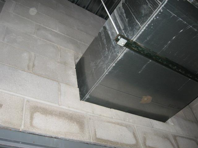
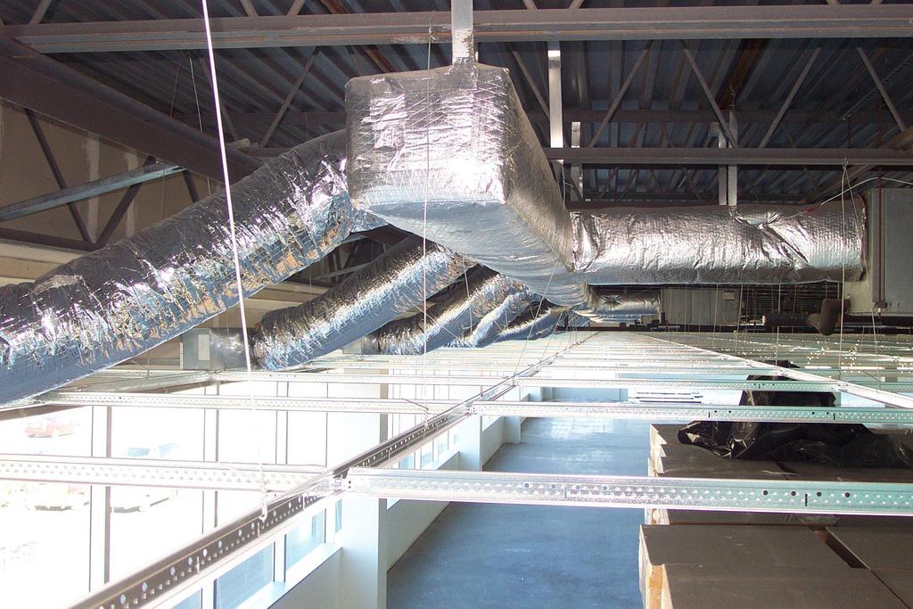
58 Duct and plenum insulation and sealing All supply and return air ducts and plenums shall be insulated with a minimum of R-5 insulation when located in unconditioned spaces and a minimum of R-8 insulation when located outside the building. When located within a building envelope assembly, the duct or plenum shall be separated from the building exterior or unconditioned or exempt spaces by a minimum of R-8 insulation. Except When located within equipment or inside the thermal envelope When less than a 15 design temperature differential between the interior and exteriorof the duct or plenum

59 Insulation for energy code or for potential condensation?
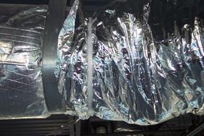
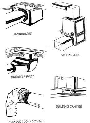
60 Duct, air handlers and filter boxes Fastened and sealed per NCMC Welds, gaskets, mastics, mastic plus embedded fabric, tapes
61 Duct Sealing Table UL 181 A Tapes and mastics ductwork UL 181 A-P Pressure sensitive UL 181 A-M Mastic UL 181 A-H Heat sensitive tape UL 181 B Tapes and mastics flexible air ducts and air connectors UL 181 B-FX Pressure sensitive tape UL 181 B-M Mastic UL 181 C Mechanical fasteners flexible nonmetallic air duct Unlisted tape (40 mile an hour tape) cannot be used No duct sealing when exposed within the space served by the duct for lowpressure duct systems
62 Duct Construction Duct construction per the NC Mechanical Code Seams and connections Longitudinal, transverse, joints and seams Sealed Low pressure ducts supply and return 2 psi Welds, gaskets, mastics, tapes Installed per the manufacturer Medium pressure ducts and plenums > 2psi and < 3 psi Sealed per section High pressure ducts > 3 psi Sealed per section Leak tested Pressure indicated on construction documents
63 High pressure ducts are leak tested to SMACNA HVAC Air Duct Leakage Test Manual Rate of leakage less than 6.0 Air leakage = F x P 0.65 F = measured leakage rate in cfm per 100 ft 2 of duct surface P = static pressure of the test Test at least 25% of duct system Documentation of the required testing shall be furnished by the designer
64 Here are some duct insulation and sealing examples...

65 Vibration Duct Joint
66
67
68

69 Duct sealing
70 Piping insulation required per Table TABLE MINIMUM PIPE INSULATION (thickness in inches) Fluid NOMINAL PIPE DIAMETER 1.5 > 1.5 Steam 1 ½ 3 Hot water 1 ½ 2 Chilled water, brine or refrigerant 1 ½ 1 ½ Note: Section requires all piping services as part of a heating and cooling system to be thermally insulated in accordance with Table
71 Piping insulation required per Table Exceptions 1. Factory-installed piping within HVAC equipment tested and rated in accordance with a test procedure referenced by this code. 2. Factory-installed piping within room fan-coils and unit ventilators tested and rated according to AHRI 440 (except that the sampling and variation provisions of Section 6.5 shall not apply) and 840, respectively. 3. Piping that conveys fluids that have a design operating temperature range between 55 F (13 C) and 105 F (41 C). 4. Piping that conveys fluids that have not been heated or cooled through the use of fossil fuels or electric power. 5. Runout piping not exceeding 4 feet (1219 mm) in length and 1 inch (25 mm) in diameter between the control valve and HVAC coil. 6. Refrigerant suction piping located in conditioned space is not required to be insulated other than as may be necessary for preventing the formation of condensation.
72 HVAC System Completion: Prior to the issuance of a certificate of occupancy, the following shall be completed: System balancing. All HVAC systems shall be balanced by contractor Air systems balancing. Each supply air outlet and zone terminal device shall be equipped with means for air balancing in accordance with the requirements of Chapter 6 of the North Carolina Mechanical Code Hydronic systems balancing. Individual hydronic heating and cooling coils shall be equipped with means for balancing and pressure test connections. Hydronic systems shall be balanced in a manner to first minimize throttling losses, then the pump impeller shall be trimmed or pump speed shall be adjusted to meet design flow conditions.
73 Manuals The manual shall include, at least, the following: 1. Equipment capacity (input and output) and required maintenance actions. 2. Equipment operation and maintenance manuals. 3. Name and address of at least one service. 4. HVAC system control maintenance and calibration information, including wiring diagrams, schematics, and control sequence descriptions. Desired or field-determined setpoints shall be permanently recorded on control drawings, at control devices or, for digital control systems, in programming comments. 5. A complete written narrative of how each system is intended to operate. 6. Name and addresses of designers of record, contractors, subcontractors and equipment suppliers.
74
75 Air system design and control Total fan system motor nameplate horsepower exceeding 5 horsepower and must be met
76 Allowable fan horsepower. Each HVAC system at fan system design conditions shall not exceed the allowable fan system motor nameplate hp (Option 1) or fan system bhp (Option 2) as shown in Table (1). This includes supply fans, return/relief fans, and fan-powered terminal units associated with systems providing heating or cooling capability. Exceptions: 1. Hospital and laboratory systems that utilize flow control devices on exhaust or return to maintain space pressure relationships necessary for occupant health and safety or environmental control shall be permitted to use variable volume fan power limitation. 2. Individual exhaust fans with motor nameplate horsepower of 1 hp or less. 3. Fans exhausting air from fume hoods. (Note: If this exception is taken, no related exhaust side credits shall be taken from Table (2) and the Fume Exhaust Exception Deduction must be taken from Table (2).
77
78 Option 1: Fan system motor nameplate hp Hp = The maximum combined motor nameplate horsepower Calculation for allowable motor hp is as follows: Constant volume = hp CFMs * Variable volume = hp CFMs * CFMs = The maximum design supply airflow rate to conditioned spaces served by the system in cubic feet per minute
79
80 Option 2: Fan system bhp Calculation for allowable fan system bhp is as follows: Constant volume = bhp CFMs * A Variable volume = bhp CFMs * A CFM S = The maximum design supply airflow rate to conditioned spaces served by the system in cubic feet per minute A = Sum of (PD x CFM D / 4131) PD = Each applicable pressure drop adjustment from Table (2) in w.c. CFM D = Design airflow through each applicable device in Table (2) Bhp = The maximum combined fan bhp
81 Motor nameplate brake horsepower (alternative to using ) Limits size of motors for fans For each fan, the fan motor shall be no larger than the first available motor size greater than the brake horsepower (bhp) Bhp shall be indicated on the design documents For example, if a motor rated at 8 bhp is required and available sizes are 7, 9 and 10 then 9 can be used
82 Motor nameplate brake horsepower exceptions 1. For fans less than 6 bhp, where the first available motor larger than the brake horsepower has a nameplate rating within 50 percent of the bhp, selection of the next larger nameplate motor size is allowed. 2. For fans 6 bhp and larger, where the first available motor larger than the bhp has a nameplate rating within 30 percent of the bhp, selection of the next larger nameplate motor size is allowed. * The fan bhp shall be indicated on the design documents to allow for compliance verification by the code official
83 Heating outside a building Outside heat shall be radiant Controlled by occupant sensors or timers De-energized when no one present
84 Simple HVAC systems and Equipment (Prescriptive) Type of equipment Unitary or packaged equipment Tables (1) through (5) One zone / One thermostat / Two pipe heating systems with no cooling serving one or more zones Does not apply to certain complex systems
85 Unitary Heat Pump One or more factory-made assemblies that include an indoor conditioning coil, compressor(s) and outdoor coil or refrigerantto-water heat exchanger, including means to provide both heating and cooling functions. When heat pump equipment is provided in more than one assembly, the separate assemblies shall be designed to be used together.
86 Unitary Heating and Cooling Equipment One or more factory-made assemblies that include an evaporator or cooling coil, a compressor and condenser combination, and that shall be permitted to include a heating function as well. When heating and cooling equipment is provided in more than one assembly, the separate assemblies shall be designed to be used together.
87 Unitary Packaged Each package is a stand alone system which provides all of the heating and cooling requirements for the area of the building that it serves
88 Economizers
89 Cooling Systems Supply air economizers shall comply with Table (1) Capable of 100% outside air with additional cooling Relieve excess outdoor air without recirculating Except: Comply with Tables (1) or (2), and exceeding the minimum efficiencies in Table (2) Air or evaporated cooled condensers with open space refrigeration Air requiring extensive filtration (polluted air)
90 Table (1) Economizer Requirements CLIMATE ZONES ECONOMIZER REQUIREMENT 1A, 1B, 2A, 7, 8 No requirement 2B, 3A, 3B, 3C, 4A, 4B 4C, 5A, 5B, 5C, 6A, 6B Economizers on all cooling systems 65,000 BTU/h a Note a: The total capacity of all systems without economizers shall not exceed 480,000 Btu/hr, or 20% of its economizer capacity, whichever is greater
91 TABLE (2) EQUIPMENT EFFICIENCY PERFORMANCE EXCEPTION FOR ECONOMIZERS CLIMATE ZONES COOLING EQUIPMENT PERFORMANCE IMPROVEMENT (EER OR IPLV) 3B 15% Efficiency Improvement 4B 20% Efficiency Improvement
92 Hydronic system controls Heat and chilled water to comfort conditioning systems At least 300,000 Btu/h design output Comply with complex system
93 COMPLEX HVAC SYSTEMS AND EQUIPMENT (Prescriptive) Systems not simple as defined in Section Typically multiple zones
94 Some types of equipment heating/cooling or both Gas - or oil-fired heaters storage greater than 140 gallons / Packaged VAV reheat / Built-up VAV reheat / Built-up single fan dual-duct VAV / Built-up or packaged dual-fan dual-duct VAV / Four pipe fan coil with central plant / Hydronic heat pump with central plant / Other multiple zone or package systems / Any combination of different simple systems such as hydronic heating and unitary packaged cooling
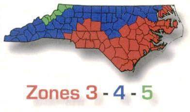
95 Economizers Comply with Table (1) Cooling systems Capable of 100% outside air with additional cooling
96 Except: 1. Systems utilizing water economizers that are capable of cooling supply air by direct or indirect evaporation or both and providing 100 percent of the expected system cooling load at outside air temperatures of 50 F (10 C) dry bulb/45 F (7 C) wet bulb and below. Exceptions 2 and 3 do not apply to North Carolina since they reference Table (2) which lists zones that don t exist in North Carolina.
97 Water Economizer A system by which the supply air of a cooling system is cooled indirectly with water that is itself cooled by heat or mass transfer to the environment, without the use of mechanical cooling
98 Variable air volume (VAV) fan control Individual fans with motors greater than 10 horsepower shall be: 1. Driven by a mechanical or electric variable speed drive Or 2. Fan motor shall have controls or devices that result in fan motor demand of No more than 30% of design wattage At 50% of air flow when static pressure setpoint equals 1/3 of total design static pressure Based on manufacturer s fan data Direct digital control

99 Hydronic system controls Heating of fluids previously mechanically cooled and the cooling of fluids previously mechanically heated shall be limited in accordance with sections through Multiple packaged boilers require sequencing controls Hydronic heating systems comprised of a single boiler and greater than 500,000 Btu/h input design capacity shall include either a multistaged or modulating burner.
100 Three pipe systems prohibited Common return line for hot or chilled water Two-pipe changeover system Common pipe for heated and chilled water Dead band of 15 F outside air temperature 4 hour operation before changeover Maximum 30 o F temperature difference at changeover
101 Hydronic (water loop) heat pump systems Shall comply with sections: : Temperature dead band : Heat rejection : Two position valve
102 Temperature dead band Hydronic heat pumps connected to a common heat pump water loop with central devices for - Heat rejection (cooling) and - Heat addition (heating) - Shall have controls capable of 20 o F dead band between initiation of heat rejection and heat addition by the central devices Except when loop temperature optimization controller is installed Heat rejection equipment Must comply with and Exception: Where heat pump system will reject heat throughout the year
103 Climate zones 3 and 4 Closed circuit cooling tower used directly in the heat pump loop automatic bypass or low leakage damper shall be provided Open-circuit cooling tower used directly in the heat pump loop automatic valve bypassing all heat pump water around the tower shall be installed Open or closed circuit cooling tower used in conjunction with separate heat exchanger to isolate cooling tower from heat pump loop, then heat loss shall be controlled by shutting down the circulation pump on the cooling tower loop
104 Climate zones 5 through 8 If open or closed circuit cooling tower is used, then separate heat exchanger to isolate cooling tower from heat pump loop and heat loss controlled By shutting down the circulation pump on cooling tower loop to provide an automatic valve to stop the flow of fluid
105 Two position valve Each hydronic heat pump on the hydronic system with total pump power exceeding 10 horsepower shall have a two-position valve
106 Part load controls Hydronic heating systems 300,000 Btu/h output design capacity supplying heated or chilled water to comfort conditioning systems shall include controls capable of: 1. Automatically reset the supply hot water temperatures using zone-return water temperature, building-return water temperature, or outside air temperature as an indicator of building heating or cooling demand. The temperature shall be capable of being reset by at least 25 percent of the design supply-to-return water temperature difference; or 2. Reduce system pump flow by at least 50 percent of design flow rate utilizing adjustable speed drive(s) on pump(s), or multiple-staged pumps where at least one-half of the total pump horsepower is capable of being automatically turned off or control valves designed to modulate or step down, and close, as a function of load, or other approved means.
107 Pump isolation Chilled water plants including more than one chiller shall have capability to reduce flow automatically through the chiller plant when a chiller is shut down Chillers piped in series for the purpose of increased temperature differential shall be considered as one chiller Boiler plants including more than one boiler shall have the capability to reduce flow automatically through the boiler plant when a boiler is shut down
108 Heat rejection equipment fan speed control Each fan powered by a motor 7.5 horsepower or greater Shall be able to operate at 2/3 of full speed or less and shall have Controls to automatically change fan speed to control leaving water temperature or condensing temperature/pressure of the heat rejection device Exception: Factory-installed heat rejection devices within HVAC equipment tested and rated in accordance with Tables (6) and (7).
109 Requirements for complex mechanical equipment serving multiple zones Multiple zones with supply air shall be VAV systems Shall include: Single duct variable air volume (VAV) systems Dual duct and mixing VAV systems Single fan dual duct and mixing VAV systems
110 During periods of occupancy VAV systems shall be capable to reduce primary air supply to a zone to one of the following before reheating, recooling or mixing takes place 1. 30% of maximum air supply to each zone cfm or less where max rate is less than 10% of total fan system supply air flow 3. Minimum ventilation requirements of Chapter 4 of the NC Mechanical Code
111 6 exceptions to VAV control requirements 1. Zones where special pressurization relationships or cross-contamination requirements are such that VAV systems are impractical. 2. Zones or supply air systems where at least 75 percent of the energy for reheating or for providing warm air in mixing systems is provided from a site-recovered or site-solar energy source. 3. Zones where special humidity levels are required to satisfy process needs. 4. Zones with a peak supply air quantity of 300 cfm (142 L/s) or less and where the flow rate is less than 10 percent of the total fan system supply airflow rate. 5. Zones where the volume of air to be reheated, recooled or mixed is no greater than the volume of outside air required to meet the minimum ventilation requirements of Chapter 4 of the International Mechanical Code. 6. Zones or supply air systems with thermostatic and humidistatic controls capable of operating in sequence the supply of heating and cooling energy to the zone(s) and which are capable of preventing reheating, recooling, mixing or simultaneous supply of air that has been previously cooled, either mechanically or through the use of economizer systems, and air that has been previously mechanically heated.
112 Single duct variable air volume (VAV) systems Shall use terminal device to reduce primary supply before reheating or recooling Dual duct and mixing VAV systems, terminal devices Systems having one warm air duct and one cool air duct shall use terminal device able to reduce flow to a minimum before mixing
113 Single fan dual duct and mixing VAV system, economizers Individual dual duct or mixing heating and cooling systems with single fan with total capacity greater than 90,000 Btu/h shall not be equipped with air economizers
114 Supply-air temperature reset controls Multiple zone HVAC controls shall include controls that automatically reset the supply temperature in response to representative building loads, or to outside air temperature The controls shall be capable of resetting the supply-air temperature at least 25% of difference between the design supply air temperature and the design room temperature Except 1. Systems that prevent reheating, recooling or mixing of heated and cooled supply air. 2. Seventy five percent of the energy for reheating is from site-recovered or site solar energy sources. 3. Zones with peak supply air quantities of 300 cfm (142 L/s) or less.
115 Heat recovery for service water heating Condenser heat recovery shall be installed for heating or reheating of service hot water given: Required when facility operates 24 hours a day and Water cooled systems exceed 6,000,000 Btu/hr of heat rejection and Water heating loads exceed 1,000,000 Btu/hr
116 The required heat recovery system shall have the capacity to provide the smaller of: 1. 60% of peak heat rejection at design conditions OR 2. The preheating required to raise the peak service hot water draw to 85 F Exceptions 1. Facilities that employ condenser heat recovery for space heating or reheat purposes with a heat recovery design exceeding 30 percent of the peak water-cooled condenser load at design conditions. 2. Facilities that provide 60 percent of their service water heating from site solar or site recovered energy or from other sources.
117 Hot gas by pass limitations Cooling systems shall not use hot gas by pass or other evaporator pressure control systems unless the system is designed with multiple steps of unloading or continuous capacity modulations Maximum bypass capacities per Table RATED CAPACITY Table MAXIMUM HOT GAS BYPASS CAPACITY 20 nominal tons (240 kbtu/h) > 20 nominal tons (240 kbtu/h) MAXIMUM HOT GAS BYPASS CAPACITY (% of total capacity) 50% 25% Exception: Unitary packaged systems with nominal cooling capacities of 7.5 tons or less (approximately 90 kbtu/h or 26.4 kw)
118 504.7 Pools and Inground Permanently Installed Spas Readily accessible on-off switch outside of heater located in plain sight Gas fired, no constant burning pilot light
119 Time switches or other control method are required to be capable of turning off heaters and pumps Heaters, motors and pumps that have built in timers are considered in compliance Except 1) Public health requires 24-hour operation 2) Required to operate solar and waste heat recovery


120 Covers Required on heated pools and permanently installed inground spas Vapor-retardant cover Except More than 70% of energy for heating from solar or heat recovery equipment computed over an operating season
121 ADDITIONAL PRESCRIPTIVE COMPLIANCE REQUIREMENTS 506 Indicate the choice on the construction documents Comply with one of the following:
122 Comply with one of the following: a More efficient mechanical equipment b Reduced lighting power density c Energy recovery ventilation systems d Higher efficiency service water heating e On-site supply of renewable energy f Automatic daylighting control systems
123 More efficient mechanical equipment The mechanical equipment would have to comply with the higher efficiency rating in the Tables This is in addition to the requirements in section 503 Tables (1), (2), (3), (4), (5), (6) and (7) These table are used similar to the Table in section 503
124 Energy recovery ventilation systems Buildings using 500 cfm or more outdoor air shall have heat or energy recovery ventilation systems for at least 80 percent of ventilation air The recovery system shall provide a change in the enthalpy of the outdoor air supply of 50 percent or more of the difference between the outdoor air and return air at design conditions Provision shall be made to bypass or control the energy recovery system to permit cooling with outdoor air where cooling with outdoor air is required
125 On-site supply of renewable energy On-site renewable energy source for 3% or more of the total building energy load On-site power generation using a non-renewable source cannot be used to satisfy this requirement The jurisdiction shall be provided with an energy analysis as described in Section 506 that documents the renewable energy contribution to the building or a calculation demonstrating that the on-site supply of renewable energy: 1) is capable of providing at least 3% of the total energy load of the building, or 2) provides on-site renewable energy generation with a nominal (peak) rating of 175 BTU's or 0.50 watts per square foot of building.
126 TOTAL BUILDING PERFORMANCE SECTION 507 The Total Building Performance method is used to determine compliance The following shall be included: Heating systems, cooling systems, service water heating, fan systems, lighting power, receptacle loads, process loads Use of this method will require a registered design professional
127 Compliance with the following sections is mandatory Air leakage Provisions to all mechanical systems Service water heating Temperature controls Heat traps Pipe insulation Hot water systems Pools and permanent in-ground spas
128 Compliance with the following sections is mandatory (continued) General Lighting controls Tandem wiring Exit signs Interior lighting power Exterior lighting Electrical energy consumption
129 Analysis procedure Determine annual energy costs for a proposed design as compared to a standard design; energy prices determined from an approved source, such as the US Department of Energy 8,760 hours per year in calculation Use local energy costs On-site non-depletable energy omitted from costs for proposed design
130 Documentation Compliance report Shows annual energy cost for proposed design is less than the standard reference design energy cost Include: - Address of building - Provide inspection checklist and details of component construction as listed in Table (1) - Name of person completing report - Name and version of software compliance tool - Annual energy cost for the proposed design and the standard reference design
131 Additional documentation The Code Official shall be permitted to require the following documents: Building component characteristics Floor plans showing thermal zones for proposed and reference designs Input and output reports showing energy totals Explanation of error warning totals Explanation of error warning messages Certificate signed by the builder showing component characteristics of the proposed design Proposed design per Table (1)
132 507.5 Calculation procedure Building specifications Show reference and proposed design - use the same method as specified by Table (1) Thermal blocks Show reference design and proposed design -use the same thermal blocks as required in Section , or Tables (1), (2), ), (4), (5) define the requirements for configuring and analyzing building models
133 HVAC zones designed Each HVAC zone shall be modeled as a separate thermal block Exceptions: Different HVAC zones shall be combined to create a single thermal block provided: 1. Space use classification the same 2. Glazing facing the same orientation or within 45 degrees of each other 3. All zones served by the same HVAC system or same type of HVAC system
134 HVAC zones not designed Thermal blocks defined on similar internal loads The following guidelines shall be used in the definition of the thermal blocks - Interior blocks more than 15 feet from exterior wall - Exterior blocks closer than 15 feet from exterior wall - Separate zone for each orientation - Separate blocks for ground floor or exposed to ambient conditions - Separate blocks with exterior ceilings or roofs from other floors
135 Multifamily residential buildings One thermal block per unit unless similar orientation Corner units and units with roof or floor loads shall only be combined with units sharing these features
136 Calculation software tools Computer generation of the standard reference design using only the input for the proposed design and not allow the user to directly modify the building component 2. Building operation for a full calendar year (8,760 hours) 3. Climate data for a full calendar year (8,760 hours) 4. Ten or more thermal zones 5. Thermal mass effects 6. Hourly variations in occupancy, illumination, receptacle loads, thermostat settings, mechanical ventilation, HVAC equipment availability, service hot water usage and any process loads 7. Part-load performance curves for mechanical equipment. 8. Capacity and efficiency correction curves for mechanical heating and cooling equipment 9. Printed code official inspection checklist listing each of the proposed design component characteristics from Table (1) determined by the analysis to provide compliance
137 Specific approval Performance analysis tools meeting the applicable sub-sections of Section 507 and tested according to ASHRAE Standard 140 shall be permitted to be approved.
138 Input Values Input values not specified from sections 502, 503, 504, and 505 shall be taken from an approved source
139 ASHRAE edition: Energy Standard for Buildings Except Low-rise Residential Buildings Designer choice Required by code: If more than 30% fenestrations Fenestration 30% or less above grade: designer choice Follow Appendix G Requires registered design professional
140 Provide additional energy conservation requirements Performance rating method Mandatory sections 5.4 Building Envelope 6.4 Heating, Ventilating, and Air Conditioning Systems 7.4 Service Water Heating 8.4 Voltage Drop 9.4 Lighting Systems 10.4 Electric Motors
141 Performance calculations Programs which can be used DOE-2, BLAST, EnergyPlus Create a proposed and baseline design Both use same weather data and energy rates Baseline calculations per Table G3.1
142 North Carolina COMcheck

143 North Carolina COMcheck
144 Mechanical Plan Review Objectives Method of Compliance HVAC Systems Ductwork Special Requirements Efficiency Ratings Documentation
145 Appendix B: 2012 Building Code Summary for All Commercial Projects

146 PROPERTIES On passing, 'Finish' button: On failing, 'Finish' button: Allow user to leave quiz: User may view slides after quiz: Goes to Next Slide Goes to Next Slide After user has completed quiz At any time
147 Questions This concludes Module 7: Commercial Mechanical All questions should be directed to the staff of the NC Department of Insurance, Engineering Division, Code Services Section. The primary contact for energy code questions is the Chief Energy Code Consultant: Mr. Dan Dittman,
2009 IECC Commercial Mechanical Requirements
 BUILDING ENERGY CODES UNIVERSITY 2009 IECC Commercial Mechanical Requirements Ken Baker PNNL-SA-66171 Learning(Objec-ves(( ( 1. Find(minimum(equipment(efficiency(requirements( and(recite(at(least(3(common(terms(for(measuring(
COMcheck Software Version Review Mechanical Compliance Certificate
 COMcheck Software Version 4.0.7.2 Review Mechanical Compliance Certificate Section 1: Project Information Energy Code: 2014 Oregon Energy Efficiency Specialty Code Project Title: Benton County Health Project
COMcheck Software Version Mechanical Compliance Certificate
 COMcheck Software Version 3.8.2 Mechanical Compliance Certificate 90.1 (2007) Standard Section 1: Project Information Project Type: New Construction Project Title : Rudy's Star Motors Construction Site:
August 15, 2013 Page 1 of 19
 Section C401 Application Compliance with C402, C403, C404 and C405 AND (either C406.2, C406.3 or C406.4) Compliance with C402, C403, C404 or C405 Section C402 Building Envelope (Climate Zone 5A) Space-Conditioning
COMcheck Software Version Mechanical Compliance Certificate
 COMcheck Software Version 4.0.3.0 Mechanical Compliance Certificate Section 1: Project Information Energy Code: 2014 Oregon Energy Efficiency Specialty Code Project Title: AHSC (Asian Heal Service Center
HVAC Mandatory Provisions Part II, Page 1
 HVAC Mandatory Provisions Part II, Page 1 Mandatory Equipment Efficiency Worksheet (6.4.1.1) System Equipment Type Size Category (Tables 6.8.1A through K) Sub-Category or Rating Condition Units of Efficiency
1. When using the COMcheck software, the compliance report submitted by the permit holder shall indicate that the applicable code is.
 2018 NC Energy Conservation Code Commercial Mechanical Module 7 CHAPTER 5 [CE] WORKSHEET 1. When using the COMcheck software, the compliance report submitted by the permit holder shall indicate that the
COMMERCIAL ENERGY EFFICIENCY
 CHAPTER 5 COMMERCIAL ENERGY EFFICIENCY This chapter has been reformatted; some deletions are not marked. SECTION 501 GENERAL 501.1 Scope. The requirements contained in this chapter are applicable to commercial
COMcheck Software Version Interior Lighting Compliance Certificate
 Section 1: Project Information Energy Code: 2009 IECC Project Type: New Construction COMcheck Software Version 4.0.2.8 Interior Lighting Compliance Certificate Construction Site: Owner/Agent: Designer/Contractor:
COMcheck Software Version Mechanical Compliance Certificate
 COMcheck Software Version 4.0.6.2 Mechanical Compliance Certificate Project Information Energy Code: Location: Climate Zone: Project Type: 90.1 (2007) Standard HALCYON Bldg. 400 Alpharetta, Georgia 3a
COMcheck Software Version Interior Lighting Compliance Certificate
 Section 1: Project Information Energy Code: 2009 IECC Project Title: Berry Farms Animal Hospital Project Type: New Construction COMcheck Software Version 4.0.3.0 Interior Lighting Compliance Certificate
COMcheck Software Version Mechanical Compliance Certificate
 COMcheck Software Version 4.0.8.1 Mechanical Compliance Certificate Project Information Energy Code: Location: Climate Zone: Project Type: 90.1 (2013) Standard Buda, Texas 2a New Construction Construction
COMMERCIAL ENERGY EFFICIENCY
 CHAPTER 5 COMMERCIAL ENERGY EFFICIENCY SECTION 501 GENERAL 501.1 Scope. The requirements contained in this chapter are applicable to commercial buildings, or portions of commercial buildings and to multiple-family
ASHRAE WILL GIVE YOU THE WORLD. This ASHRAE Distinguished Lecturer is brought to you by the Society Chapter Technology Transfer Committee
 ASHRAE WILL GIVE YOU THE WORLD This ASHRAE Distinguished Lecturer is brought to you by the Society Chapter Technology Transfer Committee Complete the Distinguished Lecturer Event Summary Critique CTTC
INDEX. ADDITIONS AND ALTERATIONS Defined Requirements ADMINISTRATION AND ENFORCEMENT... Chapter 1 AIR ECONOMIZERS
 A ADDITIONS AND ALTERATIONS Requirements........................ 101.4.3 ADMINISTRATION AND ENFORCEMENT..................... Chapter 1 AIR ECONOMIZERS Defined.................................202 Requirements........
Mechanical Compliance Certificate
 COMcheck Software Version 4.0.7.0 Mechanical Compliance Certificate Project Information Energy Code: Location: Climate Zone: Project Type: 90.1 (2013) Standard Austin, Texas 2a (weather data: TBD) New
2006 Washington State Nonresidential Energy Code Compliance Form Washington State Nonresidential Energy Code Compliance Forms Revised July 2007
 Mechanical Summary 2006 Washington State nresidential Energy Code Compliance Form MECH-SUM 2006 Washington State nresidential Energy Code Compliance Forms Revised July 2007 Project Info Project Address
High Performance Building Guide 1
 Description This Guide is intended to be used for projects with a Vermont Certified: High Performance energy efficiency goal. This High Performance goal is a whole-building efficiency approach rather than
1 - This title will copy onto other forms Date
 2015 Washington State Energy Code Compliance Forms for Commercial, R2 and R3 over 3 stories and all R1 Mechanical Summary MECH-SUM Project Title: 1 - This title will copy onto other forms Date 1/1/2015
Inspection Phase Three. Mechanical, Electrical & Plumbing Section 503
 Inspection Phase Three Mechanical, Electrical & Plumbing Section 503 COMCheck Mechanical Field Inspection Checklist Mechanical Mechanical, Electrical & Plumbing Equipment Efficiencies But a lot ore too
SESSION Michigan Energy Code (MEC) Update (3 Technical) Per SMACNA Standard (TAB, Duct Design) and ASHRAE ( ) ASHRAE Detroit Members:
 Update (3 Technical) Per SMACNA Standard (TAB, Duct Design) and ASHRAE ( ) ASHRAE Detroit Members:") SESSION 1-2015 Michigan Energy Code (MEC) Update (3 Technical) Per SMACNA Standard (TAB, Duct Design) and ASHRAE (90.1.2013) ASHRAE Detroit Members: AM Session is eligible for (X) Professional Development
SESSION 1-2015 Michigan Energy Code (MEC) Update (3 Technical) Per SMACNA Standard (TAB, Duct Design) and ASHRAE (90.1.2013) ASHRAE Detroit Members: AM Session is eligible for (X) Professional Development
INTRODUCTION TO: ASHRAE STANDARD 90.1, HVAC System Requirements for Reducing Energy Consumption in Commercial Buildings
 INTRODUCTION TO: ASHRAE STANDARD 90.1, 2013 HVAC System Requirements for Reducing Energy Consumption in Commercial Buildings Rocky Mountain ASHRAE Technical Conference, April 29, 2016 SEAN BEILMAN, P.E.,
ASHRAE/IESNA Standard
 ASHRAE/IESNA Standard 90.1-1999 An inside look at the requirements of Standard 90.1-1999 Energy Standard for Building Except Low-Rise Residential Building Mick Schwedler, PE Sr. Principal Applications
COMcheck Software Version Mechanical Compliance Certificate
 COMcheck Software Version 4.0.4. Mechanical Compliance Certificate Project Information Energy Code: Location: Climate Zone: Project Type: 205 IECC Dallas, Texas 3a New Construction Construction Site: 56
2009 Washington State Non-Residential Energy Code Scott Rushing, PE, LEED AP - Rushing Company Lisa Rosenow, CSBA, LEED AP NEEC
 2009 Washington State Non-Residential Energy Code Scott Rushing, PE, LEED AP - Rushing Company Lisa Rosenow, CSBA, LEED AP NEEC Mechanical Systems Agenda Changes in NREC Chapter 11 Changes in NREC Chapter
PRE-PRINT APPENDIX E GREEN MECHANICAL CODE SUPPLEMENT
 GREEN MECHANICAL CODE SUPPLEMENT E 101.0 General. E 101.1 Scope Applicability. The purpose of this appendix is to provide a comprehensive set of technically sound provisions that encourage sustainable
2011 Manitoba Energy Code for Buildings (MECB) PART 5, Heating, Ventilating and Air-conditioning Systems
 PART 5, Heating, Ventilating and Air-conditioning Systems") 2011 Manitoba Energy Code for Buildings (MECB) PART 5, Heating, Ventilating and Air-conditioning Systems Dieter Bartel, Manitoba Hydro September 17 th, 2014 Outline Scope and compliance Prescriptive path
2011 Manitoba Energy Code for Buildings (MECB) PART 5, Heating, Ventilating and Air-conditioning Systems Dieter Bartel, Manitoba Hydro September 17 th, 2014 Outline Scope and compliance Prescriptive path
READ ONLY. Adopting Agency BSC SFM. Adopt Entire Chapter Adopt Entire Chapter as amended (amended sections listed below)
") CALIFORNIA MECHANICAL CODE MATRIX ADOPTION TABLE APPENDIX E SUSTAINABLE PRACTICES (Matrix Adoption Tables are non-regulatory, intended only as an aid to the user. See Chapter 1 for state agency authority
CALIFORNIA MECHANICAL CODE MATRIX ADOPTION TABLE APPENDIX E SUSTAINABLE PRACTICES (Matrix Adoption Tables are non-regulatory, intended only as an aid to the user. See Chapter 1 for state agency authority
COMcheck Software Version Mechanical Compliance Certificate
 COMcheck Software Version 3.9.4 Mechanical Compliance Certificate 01 IECC Section 1: Information Type: Addition Title : Construction Site: Owner/Agent: Designer/Contractor: 3030 North Industrial Way Castle
Equipment Specifications and Required Information Quantity Rebate
 Rebate not to exceed 50% of the cost of equipment. Recycling rebates qualify for the entire rebate, regardless of the recycling cost. Equipment must be purchased or recycled in 2016. Installed equipment
COMcheck Software Version
 COMcheck Software Version 4.0.4. Mechanical Compliance Certificate Project Information Energy Code: Location: Climate Zone: Project Type: 205 IECC Salt Lake City,Utah 5b New Construction Construction Site:
Appendix 13. Categories of Cooling and Heating systems
 EcoShopping - Energy efficient & Cost competitive retrofitting solutions for Shopping buildings Co-funded by the European Commission within the 7 th Framework Programme. Grant Agreement no: 609180. 2013-09-01
ERRATA SHEET FOR ANSI/ASHRAE/IES STANDARD (I-P Edition) Energy Standard for Buildings Except Low-Rise Residential Buildings.
 Energy Standard for Buildings Except Low-Rise Residential Buildings.") ERRATA SHEET FOR ANSI/ASHRAE/IES STANDARD 90.1-2013 (I-P Edition) Energy Standard for Buildings Except Low-Rise Residential Buildings July 7, 2017 The corrections listed in this errata sheet apply to ANSI/ASHRAE/IES
ERRATA SHEET FOR ANSI/ASHRAE/IES STANDARD 90.1-2013 (I-P Edition) Energy Standard for Buildings Except Low-Rise Residential Buildings July 7, 2017 The corrections listed in this errata sheet apply to ANSI/ASHRAE/IES
Address Account # Member # Equipment Specifications Quantity Rebate. ENERGY STAR Appliances
 Rebate not to exceed cost of high efficiency equipment. Equipment must be purchased or recycled in 2015. Installed equipment must be on cooperative's lines. Submit the documentation listed below no later
Technical Development Program. COMMERCIAL HVAC PACKAGED EQUIPMENT Split Systems PRESENTED BY: Ray Chow Sigler
 Technical Development Program COMMERCIAL HVAC PACKAGED EQUIPMENT Split Systems PRESENTED BY: Ray Chow Sigler Menu Section 1 Section 2 Section 3 Section 4 Section 5 Section 6 Section 7 Introduction System
Guide Spec Summary. Option List. Date: 05/21/2001. EarthWise VAV Terminal Units Full Spec. Prepared by: Phone Number: Prepared for:
 Date: 05/21/2001 Time: 02:57:44 PM Job Name: EarthWise VAV Terminal Units Full Spec Location: AnyTown, Earth Prepared by: Phone Number: Prepared for: Guide Spec Summary Option List SINGLE & DUAL DUCT UNIT
Massachusetts Energy Code Compliance Support Commercial Energy Code Building Mechanical & Service Water Heating Provisions
 Massachusetts Energy Code Compliance Support 2015 Commercial Energy Code Building Mechanical & Service Water Heating Provisions Codes and Standards Initiative - Sponsors Your Instructor Stephen Turner
AIR-CONDITIONING SYSTEMS AND APPLICATIONS. Abdullah Nuhait Ph D. King Saud University
 AIR-CONDITIONING SYSTEMS AND APPLICATIONS Abdullah Nuhait Ph D. King Saud University AIR-CONDITIONING SYSTEMS Earliest air conditioning system used only for heating (winter) Provided heated air for comfort
AHRI Certification Program Scopes - COOLING
 Air-to-Air Energy Recovery Ventilators (AHRI Std. 1060) Automatic Commercial Ice-Cube Machines and Ice Storage Bins (AHRI Stds. 810 & 820) Central Station Air-Handling Units (AHRI Std. 430) Commercial
ONTARIO BUILDING CODE AND SUPPLEMENTARY STANDARD SB-10 PROJECT INFORMATION. Mechanical Designer Information*
 ONTARIO BUILDING CODE AND SUPPLEMENTARY STANDARD SB-10 PROJECT INFORMATION Project: Building Permit Application No.: DETAILED FORMS Location: Date: Architectural Designer Information* Mechanical Designer
Energy-Efficiency Measures List
 Guidelines for Public Agencies Energy-Efficiency Measures List 1.0 Envelope 1.1 Reduce Heat Losses-Ceiling/roof 1.11 Additional Ceiling/Roof Insulation 1.12 Exhaust Attics 1.13 Use Light-Colored Roof Surfaces
Summary Comparison of Simulation Program Features
 Summary Comparison of Simulation Program Features FEATURE DOE2.2 equest TRACE 700 HAP Public/Proprietary Public Domain Proprietary Proprietary Proprietary Simulation Method 8760 hours 8760 hours 8760 hours
UNIVERSITY OF MISSOURI Heating Ventilating and Air-Conditioning (HVAC) 2016 Q1
 2016 Q1") GENERAL: This section provides general standards for overall sizing and design of Heating, Ventilating, and Air Conditioning (HVAC) systems. Other sections contain specific standards for each system per
GENERAL: This section provides general standards for overall sizing and design of Heating, Ventilating, and Air Conditioning (HVAC) systems. Other sections contain specific standards for each system per
CHAPTER 4. HVAC DELIVERY SYSTEMS
 CHAPTER 4. HVAC DELIVERY SYSTEMS 4.1 Introduction 4.2 Centralized System versus Individual System 4.3 Heat Transfer Fluids 4.4 CAV versus VAV Systems 4.5 Common Systems for Heating and Cooling 4.6 Economizer
ATTACHMENT D #1 - HVAC (OIL) - SINGLE FAMILY DWELLINGS Category C: OIL
 - SINGLE FAMILY DWELLINGS Category C: OIL") LINE ITEM # ATTACHMENT D #1 - HVAC (OIL) - SINGLE FAMILY DWELLINGS Category C: OIL LINE ITEM DETAIL Labor Material FURNACE COMPONENTS 1 Furnish & Install Sight-Impaired Thermostat For Heating and Cooling
LINE ITEM # ATTACHMENT D #1 - HVAC (OIL) - SINGLE FAMILY DWELLINGS Category C: OIL LINE ITEM DETAIL Labor Material FURNACE COMPONENTS 1 Furnish & Install Sight-Impaired Thermostat For Heating and Cooling
COMMERCIAL HVAC PACKAGED EQUIPMENT. Split Systems
 COMMERCIAL HVAC PACKAGED EQUIPMENT Split Systems Technical Development Programs (TDP) are modules of technical training on HVAC theory, system design, equipment selection and application topics. They are
SECTION AIR-SOURCE UNITARY HEAT PUMPS
 PART 1 - GENERAL 1.1 DESCRIPTION SECTION 23 81 43 AIR-SOURCE UNITARY HEAT PUMPS SPEC WRITER NOTES: 1. Delete between // // if not applicable to project. Also delete any other item or paragraph not applicable
August 27, Section 3.2 Definitions. On page 11 delete the following definition:
 ERRATA SHEET FOR THE FIRST PRINTING OF ANSI/ASHRAE/IESNA STANDARD 90.1-2004 (SI edition) Energy Standard for Buildings Except Low-Rise Residential Buildings August 27, 2009 The corrections listed in this
Gil Rossmiller. In the construction industry for over 30 years. ICC IRC Plumbing & Mechanical Code Development Committee
 Gil Rossmiller In the construction industry for over 30 years ICC IRC Plumbing & Mechanical Code Development Committee ICC- IECC Commercial Energy Code Development Committee Building Official Parker, Colorado
Method to test HVAC equipment at part load conditions
 IPLV Method to test HVAC equipment at part load conditions For water cooled chillers: 100% load ( % hrs) + 75% ( Hrs ) + 50% ( Hrs ) + 25% ( Hrs ) = IPLV value Manufacturer can favor this number by tweaking
Union County Vocational - Technical Schools Scotch Plains, New Jersey
 SECTION 230593 - TESTING, ADJUSTING, AND BALANCING FOR HVAC PART 1 - GENERAL 1.1 SUMMARY A. Section Includes: 1. Balancing Air Systems: a. Constant-volume air systems. b. Variable-air-volume systems. 2.
SECTION SEQUENCE OF OPERATIONS FOR HVAC CONTROLS
 SECTION 23 09 93 SEQUENCE OF OPERATIONS FOR HVAC CONTROLS PART 1 - GENERAL 1.1 SUMMARY A. This Section includes control sequences for HVAC systems, subsystems, and equipment. B. See Division 23 Section
IMC Significant Changes Summary Tier I
 2009-2015 IMC Significant Changes Summary Tier I 202 Environmental Air The definition of environmental air has been expanded through the addition of parking garage exhaust. 306.1 Access More than just
B. Use UT Austin specifications and equipment schedule format for HVAC equipment where available.
 PART 1: GENERAL 1.01 General Requirements A. This standard is intended to provide useful information to the Professional Service Provider (PSP) to establish a basis of design. The responsibility of the
Topic 2. ME 414/514 HVAC Systems Overview Topic 2. Equipment. Outline
 ME 414/514 HVAC Systems Overview Equipment Outline 2-1 The Complete System 2-2 The Air-Conditioning and Distribution System 2-3 Mechanical Equipment Air-handling Equipment Heating Equipment Boilers Furnaces
Guidelines for energy efficient heating, ventilation and air conditioning (HVAC) systems
 systems") Guidelines for energy efficient heating, ventilation and air conditioning (HVAC) systems If you're a designer or a BCA, this guidance on the energy efficiency of HVAC systems in commercial buildings may
Guidelines for energy efficient heating, ventilation and air conditioning (HVAC) systems If you're a designer or a BCA, this guidance on the energy efficiency of HVAC systems in commercial buildings may
8 5.11: Finned-Tube Coils and Heat Exchangers : Humidifiers and Water Spray Systems : Access for Inspection, Cleaning, and Maintenance
 Table of Contents 3 Executive Summary 4 Building Overview 5 Mechanical Systems Overview 6 ASHRAE Standard 62.1 2013 Evaluation 6 Section 5: Systems and Equipment 6 5.1: Ventilation Air Distribution 6 5.2:
The Creative and Performing Arts High School (CAPA) Pittsburgh, PA 11/11/2002 Andrew Tech Mechanical Option Prof. S. A. Mumma
 Pittsburgh, PA 11/11/2002 Andrew Tech Mechanical Option Prof. S. A. Mumma") Objectives and Requirements For the Creative and Performing Arts High School (CAPA), the main objective of the mechanical design is to provide an energy efficient system that is easily maintainable and
Objectives and Requirements For the Creative and Performing Arts High School (CAPA), the main objective of the mechanical design is to provide an energy efficient system that is easily maintainable and
Performance Rating of Variable Refrigerant Flow (VRF) Multi-split Air-conditioning and Heat Pump Equipment
 Multi-split Air-conditioning and Heat Pump Equipment") AHRI Standard 1230 with Addendum 1 2014 Standard for Performance Rating of Variable Refrigerant Flow (VRF) Multi-split Air-conditioning and Heat Pump Equipment AHRI STANDARD 1230-2014 WITH ADDENDUM 1,
AHRI Standard 1230 with Addendum 1 2014 Standard for Performance Rating of Variable Refrigerant Flow (VRF) Multi-split Air-conditioning and Heat Pump Equipment AHRI STANDARD 1230-2014 WITH ADDENDUM 1,
COMMERCIAL ENERGY EFFICIENCY
 CHAPTER 5 COMMERCIAL ENERGY EFFICIENCY SECTION 501 GENERAL 501.1 Scope. The requirements contained in this chapter are applicable to commercial buildings, or portions of commercial buildings. These commercial
Dehumidifying with Dedicated Outdoor Air
 Dehumidifying with Dedicated Outdoor Air System Configurations Figure 71. Configurations for dedicated outdoor-air systems A dedicated outdoor-air handler separately filters, cools, dehumidifies, heats,
SECTION WATER-SOURCE UNITARY HEAT PUMPS
 SECTION 23 81 46 PART 1 - GENERAL 1.1 DESCRIPTION SPEC WRITER NOTES: 1. Use this section only for NCA projects. 2. Delete between // // if not applicable to project. Also delete any other item or paragraph
SECTION TESTING, ADJUSTING, AND BALANCING FOR HVAC
 PART 1 GENERAL 1.01 SECTION INCLUDES SECTION 23 0593 TESTING, ADJUSTING, AND A. Testing, adjustment, and balancing of air systems. B. Testing, adjustment, and balancing of hydronic, steam, and refrigerating
Direct Install Program Eligible Measures Listing:
 Direct Install Program Eligible Measures Listing: a) Lighting: - DLC qualified LED Luminaires including LED linear tube replacements - Energy Star Approved LED Screw In Lamps - T8 fixture replacements
NAHB Green Home Building Guidelines. 3.1 Prerequisites. ResCheck. Energy Efficiency
 NAHB Green Home Building Guidelines Energy Efficiency 3.1 Prerequisites 3.1.1 Home is equivalent to the IESS 2003 or local energy code. Conformance shall be based on plan analysis using software. 3.1.2
SECTION TESTING, ADJUSTING, AND BALANCING FOR HVAC
 SECTION 23 05 93 PART 1 - GENERAL 1.1 DESCRIPTION SPEC WRITER NOTES: 1. Use this section only for NCA projects. 2. Delete between // // if not applicable to project. Also delete any other item or paragraph
CHAPTER LOCAL AMENDMENTS TO THE INTERNATIONAL MECHANICAL CODE 2000 EDITION
 CHAPTER 23.20 LOCAL AMENDMENTS TO THE INTERNATIONAL MECHANICAL CODE 2000 EDITION SECTIONS 23.20.100 Local Amendments To The International Mechanical Code, 2000 Edition 23.20.202 Definitions 23.20.301.14
COMMERCIAL HVAC EQUIPMENT Indoor Self-Contained Units
 COMMERCIAL HVAC EQUIPMENT Indoor Self-Contained Units Technical Development Program Technical Development Programs (TDP) are modules of technical training on HVAC theory, system design, equipment selection
City of Duluth Festival Center 04/25
 SECTION 230593 - TESTING, ADJUSTING, AND BALANCING FOR HVAC PART 1 - GENERAL 1.1 RELATED DOCUMENTS A. Drawings and general provisions of the Contract, including General and Supplementary Conditions and
AHRI Product Section and Subsection Scopes
 Air Control and Distribution Devices Product Section Air-Cooled and Evaporative Condensers Subsection Air-Cooling and Air Heating Coils Subsection Air-to-Air Energy Recovery Ventilation Product Section
INTRODUCTION HVAC BASICS AND HVAC SYSTEM EFFICIENCY IMPROVEMENT SECTION O 4/19/2012
 HVAC BASICS AND HVAC SYSTEM EFFICIENCY IMPROVEMENT SECTION O INTRODUCTION HVAC systems or Heating, Ventilating and Air-Conditioning systems control the environment for people and equipment in our facilities.
HVAC 101. The Basics of Heating, Ventilation and Air Conditioning
 HVAC 101 The Basics of Heating, Ventilation and Air Conditioning HVAC Heating, Ventilation and Air Conditioning Provides comfort for people Allows humans to exist under adverse conditions. Comfort Comfort
KINGS COUNTY JAIL EXPANSION PHASE III COUNTY OF KINGS SECTION
 SECTION 237433, PART 1 - GENERAL 1.1 RELATED DOCUMENTS A. Drawings and general provisions of the Contract, including General and Supplementary Conditions and Division 01 Specification Sections, apply to
Chiller Plant Design. Application Guide AG McQuay International. Elevation Difference. Column Height When Pump Is Off
 Application Guide AG 31-003-1 Chiller Plant Design 51.5F Return Water To Chiller Two 400 Ton Chillers Each At 300 Tons (Balanced Load) 51.5F 480 gpm Flow Through Decoupler 44F 54F Building Load 600 Tons
2016 BUILDING ENERGY EFFICIENCY STANDARDS RESIDENTIAL HVAC ALTERATIONS
 B 2016 BUILDING ENERGY EFFICIENCY STANDARDS RESIDENTIAL HVAC ALTERATIONS COMMUNITY DEVELOPMENT DEPARTMENT 345 N. EL DORADO STREET STOCKTON, CA 95202 (209) 937-8561 www.stocktongov.com/cdd/building BUSINESS
HVAC Controls Upgrades: Requirement Details ( )
") REQUIRED CONTROLS/FEATURES To qualify the upgrade must add or substantially modify 3 or more sequences/system capabilities. Also, all sequences and items listed under the required section are needed in
REQUIRED CONTROLS/FEATURES To qualify the upgrade must add or substantially modify 3 or more sequences/system capabilities. Also, all sequences and items listed under the required section are needed in
Chapter 7: Heating and Cooling Systems
 [302.2.1] [302.1] Chapter 7: Heating and Cooling Systems Design Conditions The Washington State Energy Code sets the following conditions for heating system design and equipment sizing: Indoor Design Temperature:
BOOK 1 OVERVIEW RD2XRT INSTALLATION AND OPERATION MANUAL. Table of Contents ABOUT BOOK 1:
 4510 Helgesen Drive, Madison, WI, 53718 608.221.4499, 800.627.4499, Fax: 608.221.2824 support@renewaire.com www.renewaire.com RD2XRT INSTALLATION AND OPERATION MANUAL BOOK 1 OVERVIEW ABOUT BOOK 1: This
SECTION PACKAGED, OUTDOOR, CENTRAL-STATION AIR-HANDLING UNITS
 SECTION 237413 - PACKAGED, OUTDOOR, CENTRAL-STATION AIR-HANDLING UNITS PART 1 - GENERAL 1.1 SUMMARY A. This Section includes packaged, outdoor, central-station air-handling units (rooftop units) with the
NET ENERGY WATER LOOPS A clear path to net zero energy buildings
 Presents NET ENERGY WATER LOOPS A clear path to net zero energy buildings Alan Niles WaterFurnace International This ASHRAE Distinguished Lecturer is brought to you by the Society Chapter Technology Transfer
SECTION SEQUENCE OF OPERATIONS FOR HVAC CONTROLS
 PART 1 - GENERAL SECTION 23 09 93 SEQUENCE OF OPERATIONS FOR HVAC CONTROLS 1.1 SUMMARY A. This Section includes control sequences for HVAC systems, subsystems, and other equipment. B. See Division 23 Section
Technical Report #3 Mechanical Systems Existing Conditions Evaluation
 Mechanical Option Technical Report #3 Technical Report #3 Mechanical Systems Existing Conditions Evaluation Instructor: Dr. Bahnfleth 11.15.04 Building Sponsor: CCG Facilities Integration Table of Contents
Ventilation for New Low-Rise Residential Buildings July 20, 2015
 Ventilation for New Low-Rise Residential Buildings July 20, 2015 BSC Standard 01 2015 Building Science Corporation 3 Lan Drive, Suite 102 Westford, MA 01886 www.buildingscience.com Contents 1. PURPOSE...3
EADQUARTERS. Technical Report One. Stephanie Kunkel Mechanical Option
 EADQUARTERS 707 N. Calvert St. Technical Report One ASHRAE Standard 62.1 Ventilation ASHRAE Standard 90.1 Energy Design Stephanie Kunkel www.engr.psu.edu/ae/thesis/portfolios/2011/slk5061 Mechanical Option
Land Use and Environmental Service Agency (Code Enforcement) NC Mechanical Code. Table of Contents
 NC Mechanical Code. Table of Contents") Table of Contents Chapter 1 Administration Chapter 2 Definitions Chapter 3 General Regulations Chapter 4 Ventilation. Chapter 5 Exhaust Systems Chapter 6 Duct Systems Chapter 7 Combustion Air Chapter 8
Table of Contents Chapter 1 Administration Chapter 2 Definitions Chapter 3 General Regulations Chapter 4 Ventilation. Chapter 5 Exhaust Systems Chapter 6 Duct Systems Chapter 7 Combustion Air Chapter 8
Stanford University Facilities Design Guidelines SECTION DECENTRALIZED UNITARY HVAC EQUIPMENT
 SECTION 23 81 00 DECENTRALIZED UNITARY HVAC EQUIPMENT PART 1 - GENERAL 1.1 SUMMARY A. Section includes packaged roof top unit, unit controls, remote panel, roof mounting curb and base, maintenance service,
FAST AND ROBUST BUILDING SIMULATION SOFTWARE. Chilled Beam Performance: 1 Shelly Street, Sydney
 FAST AND ROBUST BUILDING SIMULATION SOFTWARE Chilled Beam Performance: 1 Shelly Street, Sydney 3D Model Creation 1 Shelley Street, Sydney 3D Model Creation 1 Shelley Street, Sydney Daylight Analysis 1
ENGINEERING. Edition No. 13 October 2002
 Edition No. 13 October 2002 ENGINEERING S Y S T E M S O L U T I O N S W e at McQuay are very proud of our tradition of producing industry leading water source heat pumps. Our heritage stretches back more
Snohomish County PUD #1 HEAT PUMP SYSTEM INSTALLATION STANDARDS
 Snohomish County PUD #1 HEAT PUMP SYSTEM INSTALLATION STANDARDS April 2018 Topic TABLE OF CONTENTS Pages A. INTRODUCTION 5 B. DEFINITIONS 5 1. Shall 5 2. Should 5 C. CUSTOMER ELIGIBILITY 5 1. Single Family
SECTION PACKAGED ROOFTOP AIR CONDITIONING UNITS
 SECTION 15732 - PACKAGED ROOFTOP AIR CONDITIONING UNITS PART 1 - GENERAL 1.1 SECTION INCLUDES A. Package roof top unit. B. Heat exchanger. C. Refrigeration components. D. Unit operating controls. E. Roof
PINNACLE SERIES DEDICATED OUTDOOR AIR SYSTEM ENERGY EFFICIENT DEHUMIDIFICATION
 ENERGY EFFICIENT DEHUMIDIFICATION PINNACLE SERIES DEDICATED OUTDOOR AIR SYSTEM Provides a very high degree of latent cooling using only a minimal amount of conventional cooling input Substantial energy
RE: Phase 2 Improvements DATE: July 1, 2016 New Administration Building Wernle Youth & Family Treatment Center 2000 Wernle Road Richmond, Indiana
 ADDENDUM NO. 2 RE: Phase 2 Improvements DATE: July 1, 2016 New Administration Building Wernle Youth & Family Treatment Center 2000 Wernle Road Richmond, Indiana TO: All Bidders Gentlemen: This Addendum
SECTION/SUBSECTION (scroll down to view more listings; this list is arranged alphabetically) SCOPE. AHRI Section-Subsection Scopes
 SCOPE. AHRI Section-Subsection Scopes") Air Control and Distribution Devices Product Section Ducted devices, used to deliver air into/or remove air from a space and which provide control of air volume, direction, temperature, and/or pressure.
Air Control and Distribution Devices Product Section Ducted devices, used to deliver air into/or remove air from a space and which provide control of air volume, direction, temperature, and/or pressure.
DIVISION 15 MECHANICAL
 DIVISION 15 MECHANICAL A. GENERAL DESIGN CONDITIONS 1. Design occupied spaces to maintain 72 F and a space dew point temperature not to exceed 55 F. 2. Design classroom and office space buildings with
SECTION TESTING, ADJUSTING, AND BALANCING FOR HVAC
 SECTION 230593 - TESTING, ADJUSTING, AND BALANCING FOR HVAC PART 1 - GENERAL 1.1 RELATED DOCUMENTS A. Drawings and general provisions of the Contract, including General and Supplementary Conditions and
AIR DISTRIBUTION. C. Section Building Automation and Control System Guidelines. D. Section Fire Alarm System & Detection Systems
 233100 AIR DISTRIBUTION PART 1: GENERAL 1.01 RELATED SECTIONS A. Section 230700 HVAC Insulation B. Section 237300 Air Handling C. Section 230900 Building Automation and Control System Guidelines D. Section
Performance Rating of Computer and Data Processing Room Air Conditioners
 ANSI/AHRI Standard 1360 (I-P) with Addendum 1 2013 Standard for Performance Rating of Computer and Data Processing Room Air Conditioners Approved by ANSI on November 8, 2013 WITH ADDENDUM 1, PERFORMANCE
CONTENTS. B. System Design and Performance Requirements
 15625 Water Chillers This document provides design standards only, and is not intended for use, in whole or in part, as a specification. Do not copy this information verbatim in specifications or in notes
wattsmart New Homes Contractor-Certified HVAC Quality Assurance (HVAC-QI)
") Contractor-Certified HVAC Quality Assurance (HVAC-QI) HVAC Quality Assurance (HVAC-QI) Checklists The following checklists are required, with all applicable items completed and checked, including final
Contractor-Certified HVAC Quality Assurance (HVAC-QI) HVAC Quality Assurance (HVAC-QI) Checklists The following checklists are required, with all applicable items completed and checked, including final
Job Name Control Systems Description Date
 Job Name Control Systems Description Date Project Overview The project is a describe the building and its major HVAC systems (e.g. three-story office building, served by a rooftop unit VAV system ). In