SERVICE MANUAL Cookers TERIM STEEL
|
|
|
- Ashley Hudson
- 6 years ago
- Views:
Transcription
 599 38 52-33 TERIM STEEL Fax +39 0434 394096 EN/SERVICE/FV SOI")
1 SERVICE MANUAL COOKING Cookers ELECTROLUX ITALIA S.p.a. Publication No. Corso Lino Zanussi, 30 I PORCIA /PN (ITALY) TERIM STEEL Fax EN/SERVICE/FV SOI Edition: Rev. 00 SOI FV 1/
2 SOI FV 2/
3 INDEX 1 - HOB GAS PARTS pag GAS RAMP pag GAS TABS pag GAS BURNERS pag BURNER SPARK PLUG pag THERMOCOUPLES pag GAS PIPE (FROM TAPS TO BURNERS) pag BURNER JETS pag MINIMUM LEVEL ADJUSTMENT pag OVENS AND HOBS ELECTRICAL PARTS pag OVEN - UPPER HEATING ELEMENTS pag OVEN - BOTTOM HEATING ELEMENT pag OVEN - FAN HATING ELEMENT pag HOB - BARBECUE AND FRY-TOP HEATING ELEMENT pag HOB - CERAMIC HEATING ELEMENTS pag OVEN THERMOSTAT pag COMMUTATORI FORNO pag SAFETY THERMOSTATS pag COOLING FAN pag ROTISSERIE MOTOR pag OVEN FAN pag ENERGY REGULATOR pag PROGRAMMER pag IGNITION SWITCH AND GENERATOR pag OVENS AND HOBS MECHANICAL PARTS pag BOTTOM DRAWER pag DISASSEMBLING THE COOKTOP pag OVEN DOOR WITH ENEMELLED COUNTERDOOR pag OVEN DOOR WITH THREE GLASSES pag HINGE ROLLERS AND SUPPORTS pag KNOBS AND BEZELS pag FREESTANDING OVEN ASSEMBLY STEPS pag. 50 SOI FV 3/


4 1 - HOB GAS PARTS GAS RAMP The picture shows the gas ramp and its assembly components. Tap rear side with coaxial thermocouple. Tap lateral side with coaxial thermocouple: same characteristics as above except for the clutch type for thermocouple with faston. SOI FV 4/


5 Two types of bezel supports: the right one works also as a support for the gas ramp. The picture shows the bracelets to fix the ramp to the front and rear supports: 1. first ramp support type. 2. intermediate ramp support. Here is the existing model of the rear ramp support. SOI FV 5/

6 The bezel fixing screws may change according to the type of bezel or knob in use. SOI FV 6/


7 1.2 - GAS TABS Replacing the tap. After removing the pipe tightening nut and after taking the thermocouple end off, by means of a spanner no.7 remove the blocking screw from the tap until the complete release of the clip. Then disconnect the catenary and remove the tap. To reassemble the new tap again, follow the removing instructions in reverse order. By this step a second operator might be necessary. After reassembling the tap it is highly recommended to test and verify there is no gas leakage. SOI FV 7/


8 1.3 - GAS BURNERS Replacing a burner. Remove the tightening nut of the gas pipe, take the external screws off, then lower the burner from inside the hob. Take the gasket out taking care not to damage it (in case it is damaged it must be replaced). Then remove the clip from the spark plug and draw it out. By means of a spanner no.8 remove the thermocouple by unscrewing the fixing nut. To reassemble the burner again, follow the removing instructions in reverse order. After reassembling the burner it is highly recommended to test and verify there is no gas leakage. SOI FV 8/

9 New gaskets have been recently put between hob and burners to seal the whole burner perimeter, including spark plug and thermocouple ( the picture shows the semi-rapid burner type). At the beginning gaskets type O-ring were used only on the spark plug and on the thermocouple; if their replacement is necessary we suggest their replacing with the new complete kind of gasket. SOI FV 9/
 according to their length. They are not interchangeable.")

10 1.4 - BURNER SPARK PLUG By ordering spark plugs pay attention to the needed model. On a same cooker you may find two different models of spike plugs (see picture) according to their length. They are not interchangeable. The longer one fits the triple ring or wok burner, while the short one fits all the remaining burners. Replacing the spark plug. Remove the screws from the burner, then lower it softly. Take the gasket out of the hob without damaging it and after drawing the blocking clip out, disconnect the spark plug and then remove it. To reassemble the spark plug again, follow the removing instructions in reverse order. SOI FV 10/

 Thermocouple with faston connection.")
11 1.5 - THERMOCOUPLES By ordering thermocouples make sure you are specifying the model you need. There are indeed three different kinds of thermocouples: as the picture shows, the long one fits the triple ring or wok burner only, while the short one has a model which fits the rapid burner only for the cooker 120 cm, 4 burners+barbecue+fryer (ex. S12FF-4BF/TF/TG/BC and so on.) Thermocouple with faston connection. This thermocouple is used no more in the present production and it can not be interchangeable with the coaxial junction model. SOI FV 11/


12 Thermocouple with coaxial junction. This thermocouple is now used in the present production and it can not be interchangeable with the faston model. Replacing the safety thermocouple. Remove the screws from the burner, then lower it softly. Take the gasket out of the hob without damaging it and by means of a spanner no.8 unscrew the blocking nut, remove the thermocouple and disconnect it from the tap. To reassemble the thermocouple again, follow the removing instructions in reverse order. SOI FV 12/

13 1.6 - GAS PIPE (FROM TAPS TO BURNERS) Replacing a gas pipe. Using a spanner no. 15 unscrew the tightening nuts of the pipe both on the tap and on the burner sides, then after taking out the pipe, verify that inside the burner thread seat there is no aluminium residue that could obstruct the nozzle, then after that checking, assemble the new pipe. In case you are using a torque wrench the tightening must be done by means of a 12 newton couple, in case you are using a normal spanner, then avoid screwing completely the nuts, in order to leave a margin to allow a further tightening in the event of leak. SOI FV 13/


14 1.7 - BURNER JETS To replace the nozzles we suggest using a screwdriver or a T - shaped spanner no.7. The diameter no. and other letters are shown on the nozzle to allow a clearer identification MINIMUM LEVEL ADJUSTMENT SOI FV 14/

15 In case of gas-type changing.. Provide the right injectors fitting the required gas type and then by means of a T- shaped spanner no 7, unscrew the injectors one by one and then replace with the ones suitable for the burner type; for this operation we recommend to follow strictly the instructions on the cooker manual (the gauge is printed on the injector). After replacing the injectors you need to adjust the minimum levels. Remove the knob and look after the small screw on the right of the tap body; by means of a small screwdriver turn completely clockwise and after turning on the burner and after putting on the minimum position, unscrew anticlockwise slowly until the flame becomes 1/3 of its maximum dimension. SOI FV 15/

16 2 - OVENS AND HOBS ELECTRICAL PARTS OVEN - UPPER HEATING ELEMENTS The pictures show the fixing points for the heating elements upper/grill in the ovens: big 90/60 multifunction oven and small 30 auxiliary oven. First make a note of the wiring, then unplug the cables. Disassemble the inner support and take it out, then unscrew the nuts or the external screws on theback, extract the heating element from the front. To reassemble, follow the removing instructions in reverse order. SOI FV 16/

17 2.2 - OVEN - BOTTOM HEATING ELEMENT Replacing the bottom heating element of the multifunction 90/60 oven and of the small 30 oven. First of all make a note of the wiring, then unplug the cables, disassemble the support on which the element is screwed, take the group out from the back and draw the heating element out of the support. To reassemble again, follow the removing instructions in reverse order. SOI FV 17/

18 2.3 - OVEN - FAN HATING ELEMENT To intervene on the fan heating element, first of all disassemble the inner air-conveyor by using a spanner no.10, then unscrew the self-tapping screw on the center of the element and then from the back unscrew the two screws. To reassemble again, follow the removing instructions in reverse order. We recommend to make a note of the position of the cables on the heating element. SOI FV 18/


19 2.4 - HOB - BARBECUE AND FRY-TOP HEATING ELEMENT The picture on the right shows the screws fixing the heating elements on the support in yellow, the screws fixing the support to the hob in red. First make a note of the wiring, then disconnect the cables. Pay attention to the digits on the perimeter of the element metal cage, since they are the reference to position the heating element with precision and to put this in line with the glass serigraphy. After this, remove the heating element. SOI FV 19/
 we suggest a screwdriver like the one shown in the picture. 2.5 - HOB - CERAMIC HEATING ELEMENTS In the picture no.")
20 It is possible to replace the heating element without disassembling the hob. Since you need to operate on a small area (about 150 mm in height) we suggest a screwdriver like the one shown in the picture HOB - CERAMIC HEATING ELEMENTS In the picture no. 47 a ceramic hob is shown overturned to display the system fixing the heating elements to the supports and these ones to the hob. Before operating make a note of the wiring then disconnect the cables. Pay attention to the digits on the perimeter of the element metal cage, since they are the reference to position the heating element with precision and to put this in line with the glass serigraphy. After this, remove the heating element. SOI FV 20/
 we suggest a screwdriver like the one shown in the picture. 2.")
21 It is possible to replace the heating element without disassembling the hob. Since you need to operate on a small area ( about 150 mm in height) we suggest a screwdriver like the one shown in the picture OVEN THERMOSTAT The picture shows the two thermostats in the big 90/60 multifunction oven and in the small 30 auxiliary oven. To replace the thermostats, first unplug the bulbs from support clips inside the oven and take them out from the back, then unplug the electric connections and then extract the thermostats out of their seats on the switches. To place the thermostats again, follow the removing instructions in reverse order. SOI FV 21/


22 2.7 - OVEN SWITCHS Elux. Code /3 Elux. Code /6 Elux. Code /7 Elux. Code /9 Elux. Code /2 Elux. Code /7 The pictures show all switch models. By their conjunction, you can obtain all combinations in use now. SOI FV 22/
 measuring the temperature. To replace the first type you need disconnecting and unscrewing it.")
.")
23 2.8 - SAFETY THERMOSTATS Here s above two models of thermostat: on the left a direct contact thermostat, while on the right a thermostat provided with a sensor (bulb) measuring the temperature. To replace the first type you need disconnecting and unscrewing it. To replace the second type you must pay attention to the bulb assembling phase, since it needs to be placed between two sheets to keep it in position (for the right one take care to put the protection). With the introduction of the new assembled muffle and new oven doors, the thermostats are put on a support which is the same on all ovens. SOI FV 23/


24 2.9 - COOLING FAN These two pictures show the fixing points for the cooling fan motors. The solution that is being used now is shown on the left. SOI FV 24/


25 ROTISSERIE MOTOR This picture shows two types of motor reducer for rotisserie: on the left the motor for the small 30 auxiliary oven, on the right the motor for the big 90/60 multifunction oven. A new kind of motor has been introduced now and it is the same on all the ovens. Warning! When replacing a motor make sure that during assembling the support has been positioned correctly. To do this, refer to the picture on the left showing the kind of assembling for the 60 oven. For a 90 oven, the support must be overturned and three holes must be visible on the pointed side. SOI FV 25/
. Before disconnecting the cables from the back, make a note of their position.")
26 OVEN FAN Removing the fan motor. Remove the air-conveyor inside the oven. By means of an appropriate tool (a coin) remove the fan nut clockwise (picture no. 113). Pay attention since this is a reverse screw thread fixing. Take out the three screws fixing the motor (picture no.114). Before disconnecting the cables from the back, make a note of their position. Disconnect and remove the motor (picture no. 116). The fiber gasket shown in the picture no. 115 is no more available. SOI FV 26/

27 ENERGY REGULATOR SOI FV 27/


28 PROGRAMMER The pictures show the screws fixing the display support. Timer fixed to the support. Timer with support and glass. SOI FV 28/

. SOI 12.")
29 IGNITION SWITCH AND GENERATOR The above pictures show the three kinds of ignition and the detail of the contact on the tap. In the picture here under you may see the ignitions without contact mass that replace the previous ones (same compatibility). SOI FV 29/


30 3 - OVENS AND HOBS MECHANICAL PARTS BOTTOM DRAWER SOI FV 30/


31 SOI FV 31/


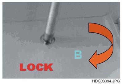
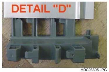
32 Clip of adjustment fastened to the running rail. To unfasten the drawer press the lever in depth. SOI FV 32/


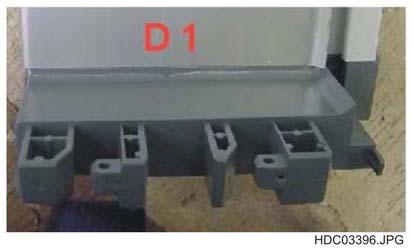
33 After pressing both levers pull the drawer. The picture shows the seating of the drawer. Insert the new drawer by placing it on the rails. SOI FV 33/


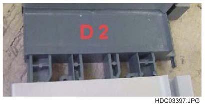
34 Push the drawer in depth. Press until the click of withholding. SOI FV 34/


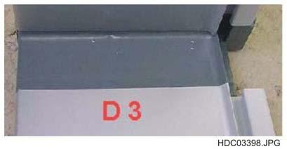
35 3.2 - DISASSEMBLING THE COOKTOP Remove the back panel and disconnect the cables from the terminal board (cookers manufactured before the year 2005) or remove the terminal board support (cookers manufactured after the year 2005). Remove the inner and external screws to unlock the hob. SOI FV 35/


36 Disconnect the hob from the base: connectors, fan power supply, ignition power supply, and so on. Unloose and remove the thermostat bulb. Push the hob forward. SOI FV 36/


37 Lift the hob of few centimetres in the back. Draw the hob out of the font studs and lift it. To reassemble again follow the above instructions in reverse order. On the reversed hob it is easy to do any kind of intervention, but this solution is to be adopted only when it is absolutely necessary. SOI FV 37/


38 3.3 - OVEN DOOR WITH ENEMELLED COUNTERDOOR The picture shows the door panel before the assembling of the counterdoor. Here is a detail of the counterdoor with the hinge in the foreground. Here is the joining of the counterdoor to the door panel: the spacer and the screw to fix the handle in the foreground, the fixing plate to fix the counterdoor to the door panel in the background. SOI FV 38/


39 3.4 - OVEN DOOR WITH THREE GLASSES Assembling a three glass oven door (any dimensions). Here is the handle fixing screw, which will be hidden by the profile carrying the inner and intermediate glass. The handle must be screwed to the front before joining to the glass group. After assembling glass and lateral profiles, the group must be coupled to the external door panel. The glass group must be inserted under the door upper frame. The glass group side carrying the set for the hinges is the lower part of the door. This need now to be lean on the lower side. SOI FV 39/


40 Insert the hinges and then join the group to the door panel. The hinges are screwed on the upper side. The profile carrying the hinges is screwed on the upper side. SOI FV 40/


41 When fixing the lower side, start from the profiles then insert the screw to fix the lower hinge. Here is the finally assembled profile. The above instructions may be useful also to replace a profile or a glass or hinges. SOI FV 41/


42 3.5 - HINGE ROLLERS AND SUPPORTS The picture shows the hinge roller that was used initially. In the sequence of pictures here below it is shown how to replace the hinge support now in use. After removing the hob, proceed as follows. Disassemble the fan motor and the conveyor. Disassemble the fan crankcase. SOI FV 42/


43 Disassemble the central back support. Unblock the front one. Unscrew the back support. SOI FV 43/


44 Unscrew the front support. Take out the lower screws that fasten the oven front side. SOI FV 44/


45 Move laterally the small oven and proceed with replacing the supports. Follow the above instructions for the other oven. By means of an appropriate tool unscrew the roller. SOI FV 45/


46 Take the roller out and replace with a new one. The above instructions may be followed also in case of rollers used till the year 2004 (see picture no.20 at the beginning of the sequence), the only difference is on the fixing being frontally and from the outside instead of laterally. To reassemble again follow the above removing instructions in reverse order KNOBS AND BEZELS Single bezel for AEG models. One piece big bezel for Electrolux models. Instructions to replace one or more bezels. The picture shows one hob. Warning! The two pointed taps must never been removed at the same time, one must always stay at its place, since behind them is located the gas ramp and in case they are removed simultaneously the alignment of the ramp may be endangered. SOI FV 46/


47 This is the inside of the hob. The two pieces in foreground are the bezels supports, the one on the right supports also the gas ramp (see previous picture), the one on the left keeps the bezels in position. Start the operation by removing all the knobs. Here are the screws fastening the bezel. SOI FV 47/


48 The picture shows the ramp support after removing the bezel. Usually this part keeps its position since the ramp supports it. Replace the bezel taking care not to force the screws and verify that the plastic pins enter the holes. Here s the support of the other bezels, when removing the screws they will tend to fall onto the tap axle, in this case, before replacing the bezel, make sure to have correctly positioned it as shown in the picture. SOI FV 48/


49 Take care to insert the screw without turning the support inside, then after one turn of the screw bring the pointed plastic pin into the hole and screw. After that insert the second screw. As an alternative, you could align the two parts with a thin screwdriver passing through the bezel hole and then trough the support hole, then insert the lower screw. SOI FV 49/


50 4 - FREESTANDING OVEN ASSEMBLY STEPS Preparing of the structure. Here is one complete structure of a 70 cm cooker. Preparing of the multifunction oven. SOI FV 50/


51 Here is the joining of the two ovens in a double oven cooker. Here is the front view of the previous picture. The picture shows the inserting of the ovens group into the structure of one double oven cooker. SOI FV 51/


52 Assembling of the air-conveyor on a double oven cooker. View of the lower part of the assembled side panel and in foreground the fastening system to the lower part of the cooker structure. The picture draws attention to the screws fastening the side panel to the hob. SOI FV 52/
. SOI 12.")
53 The picture shows an assembled side panel with its reinforcement. You may notice the rubber needed to seal the fissuring. Rear view of the cooker with the assembled hob. After the wiring, the cooker will be closed and tested (here s a double oven cooker). SOI FV 53/
Cucina genesi G10FF-4F X S Steel G20/20 230/50 EU 25/11/2007
 1037 745 132 268 684 260 745 268 260 684 132 1023 684 1667 731 623 684 1024 1061 1612 132 1014 1668 1061 1612 16 132 16 132 132 1059 CS1672. 1 Pg 1.0 260 ZS0498 Cast-iron grid for lateral cooktop 100 2
Solitaire Prof. gaselektro-fornuis Texas 120 frytop/friteuse rvs
 1038 745 132 268 745 132 268 1023 1667 1668 1024 1014 1441 490 1067 1014 1441 1612 1061 1061 1612 1050 CS1056. 1 Pg 1.0 132 BS0299 Adhesive tape 16,5 m x 19h (3M) 250 268 ZS0511 Cast-iron grid 2 burners
Cucina ascot A12FF-4BF X-C S Steel G20/20 230/50 EU 25/11/2007
 2001 2002 794 2002 731 2028 2302 1957 1957 1014 2050 1575 1441 1957 1957 1014 2053 2047 1441 1575 2480 2034 CS1682. 1 Pg 1.0 731 ZS0565 Cast-iron grid for wok 1 1014 ZS2026 Thermostat TY60 N.O. fixing
Cucina ascot A12FF-4TM X-C S Steel G20/20 230/50 EU 25/11/2007
 2001 2002 2297 794 2002 731 2028 2449 1957 1957 1014 2050 1575 1441 1957 1957 1014 2053 2047 1441 1575 2454 2034 CS1683. 1 Pg 1.0 731 ZS0565 Cast-iron grid for wok 1 1014 ZS2026 Thermostat TY60 N.O. fixing
Cucina ascot A10FF-4G X-C S Steel G20/20 230/50 EU 25/11/2007
 2000 2002 2004 2002 2004 684 2028 731 684 684 2055 2050 1957 1575 1014 1441 1957 1957 2052 2046 1575 2230 2032 CS1680. 1 Pg 1.0 N Object 684 ZS1864 Support for lateral cast-iron grid cooktop 100 4 731
Cucina ascot A10FF-6W X-C S Steel G20/20 230/50 EU 20/01/2008
 2000 2002 2004 2002 2002 2004 684 2028 731 684 684 1998 2050 1957 1575 1014 1441 1957 1957 2052 2046 1575 2082 2032 CS1434. 1 Pg 1.0 684 ZS1864 Support for lateral cast-iron grid cooktop 100 4 731 ZS0565
SERVICE MANUAL. Freestanding cooker 500 and 600 / Range Gas- gas Electric CFSGSV14 CFSGWH14 CFSESV14 CFSEWH14
 Freestanding cooker 500 and 600 / Range 2013 Gas- gas Electric CFSGSV14 CFSGWH14 CFSESV14 CFSEWH14 SERVICE MANUAL 2 Door assembly Removing the door assembly 1. Lift the lock of the left and right door
Cucina ascot A7F-4 X-C S Steel G20/20 230/50 EU 07/11/2007
 2018 2019 2019 731 2017 2028 2050 1957 1957 1014 1957 1957 2051 1575 1441 1575 2084 2044 2042 CS1402.1 Pg 1.0 731 ZS0565 Cast-iron grid for wok 1 1014 ZS2026 Thermostat TY60 N.O. fixing B 1 1441 ZS2665
Cucina genesi G10FF-6V X Steel 400/50 EU 07/11/2007
 1037 745 745 893 1023 1667 2819 1668 1024 1061 16 132 16 132 132 132 1014 1441 1061 1059 854 852 853 446 447 855 447 847 447 848 856 447 849 447 447 CS1332. 1 Pag 1.0 N Object 446 ZS1059 Heating element
Cucina genesi G7F-4V X Steel 230/50 EU 08/11/2007
 1193 745 132 745 889 132 1023 1667 890 1668 1024 1061 16 132 132 132 1441 1014 1061 446 852 16 132 1175 855 902 849 853 847 CS1554. 1 Pg 1.0 446 ZS1059 Heating element barbecue 1200/230 th.7 1 745 ZS1850
SERVICE MANUAL. Freestanding cooker 500 and 600 / Range Gas - electric Ceramic - electric Electric
 SERVICE MANUAL Freestanding cooker 500 and 600 / Range 2013 Gas - electric Ceramic - electric Electric Manual developed by: R. Stołowski E. Banach R. Bedoński 2 Address your questions to: serwis.dokumentacja@amica.com.pl
SERVICE MANUAL DISHWASHERS DIVA ACCESSIBILITY DISHWASHERS
 SERVICE MANUAL DISHWASHERS DIVA ELECTROLUX HOME PRODUCTS S.p.A. Publication no. Spares Operations Italy Corso Lino Zanussi,30 I - 33080 PORCIA /PN (ITALY) 599 38 70-09 Fax +39 0434 394096 EN DISHWASHERS
DISHWASHER - PART RECOGNITION GUIDE
 DISHWASHER - PART RECOGNITION GUIDE SPRAY ARM HOLDER UPPER SPRAY ARM FILTER ASSEMBLY LOWER SPRAY ARM ASSEMBLY SUMP DISHWASHER - PART RECOGNITION GUIDE DISPENSER DOOR SPRING DOOR HINGE INNER DOOR DOOR THERMOSTAT
Contents. 1. Instructions for safety and use 20
 Contents 1. Instructions for safety and use 20 2. Positioning in the counter top 21 2.1 Fixing to the supporting structure 21 2.2 Positioning the adhesive sponge 22 2.3 Positioning the fastening clips
Contents. 1. Instructions for safe and proper use Positioning of hob Attachment to support structure Electrical connection 22
 Contents 1. Instructions for safe and proper use 19 2. Positioning of hob 20 2.1 Attachment to support structure 20 3. Electrical connection 22 4. Gas connection 23 4.1 Connection to LPG 24 4.2 Ventilation
A NEW DIMENSION in COOKERS
 GLEM 122 The One A NEW DIMENSION in COOKERS cookers A COOKERS Matrix DESIGN with CHARACTER The new design of the Matrix series, developed in conjunction with Marcello Cutino, BCF design, represents the
GAS COOKER GAS OVEN SERIES. Owner s Manual Please read this manual carefully before operating your set. Retain it for future reference.
 GAS COOKER GAS OVEN SERIES Owner s Manual Please read this manual carefully before operating your set. Retain it for future reference. Record model number and serial number of the set. See the label attached
INSTRUCTION MANUAL BUILT-IN HOBS CIR900X
 INSTRUCTION MANUAL BUILT-IN HOBS CIR900X ENGLISH 3-19 Thank you for choosing our product. We advise you to read this manual carefully. It contains all necessary instructions for maintaining unaltered the
Commercial code: F035979
 Model type: K6G210(X)/G Commercial code: F035979 General notes Technical Documentation guidelines ----------------------------------------------------------------------------------------------------------------------------------
Installation and Operating Instructions
 Installation and Operating Instructions Models: Verso 4G Hob As part of Parmco Appliances commitment to improving and updating product ranges, we reserve the right to alter, change and update technical
USER MANUAL AKC cm 4 Burners, Stainless Steel Hob
 USER MANUAL AKC 641 60 cm 4 Burners, Stainless Steel Hob For your safety These instructions have been drawn up for your safety and that of others. You are therefore requested to read them carefully before
Cucina Enfasi E9F-6I SS Steel 230/50 EU
 4320 1957 1014 4668 1996 4211 1957 1996 5783 4266 4714 5785 5784 5753 4731 5753 129 4210 3717 5801 4751 4210 5009 3717 5765 4522 5849 4522 CS5384.1 Pg 1.0 129 601154 Timer 1 1014 ZS2026 Thermostat TY60
Contents authorised persons
 Contents 1. INSTRUCTIONS FOR SAFE AND PROPER USE 4 2. POSITIONING OF THE HOB 6 3. GAS CONNECTION 10 4. ELECTRICAL CONNECTION 11 5. ADAPTATION TO DIFFERENT TYPES OF GAS 12 6. FINAL OPERATIONS 14 7. USING
Products documentation (REVISION DATE: 03/10/2011) OMFP6010 (60cm PIROLITIC OVEN)
 OMFP6010 (60cm PIROLITIC OVEN)") Products documentation (REVISION DATE: 03/10/2011) OMFP6010 (60cm PIROLITIC OVEN) Ovens Service Manual Models OMFP6010 CONTENTS This document has been published to be used for service only. The contents
Products documentation (REVISION DATE: 03/10/2011) OMFP6010 (60cm PIROLITIC OVEN) Ovens Service Manual Models OMFP6010 CONTENTS This document has been published to be used for service only. The contents
TC MODULE (FFD) (with Gas Hob)
 (with Gas Hob)") TC MODULE (FFD) (with Gas Hob) Installation Instructions REMEMBER: when replacing a part on this appliance, use only spare parts that you can be assured conform to the safety and performance specification
TC MODULE (FFD) (with Gas Hob) Installation Instructions REMEMBER: when replacing a part on this appliance, use only spare parts that you can be assured conform to the safety and performance specification
HG 675 CX 60 HG 675 CN 60 HG 675 CW 60
 HG 675 X 60 HG 675 CX 60 HG 675 CN 60 HG 675 CW 60 1 2 1. : 93/68: 90/396: 2006/95/CE: 2004/108/CE: - 1935/2004:. 2002/95/CE: RoHS 2.,.,,,,...,. (,..)..,,.,. ( ),,, ;,,.,.....,.,,,,,,...,. (..),,.,..,.,,,,
M7S0GNA8X2AUG MAS304GASXE LP/01 - GAS COOKER - Bertazzoni Service
 M7S0GNA8XAUG MAS30GASXE LP/0 - GAS COOKER - /6 M7S0GNA8XAUG MAS30GASXE LP/0 - GAS COOKER - N Reference number Description Quantity 0 600008 WIRE T-ZERO 0 6060 CIRCUIT DIAGRAM 0 60758 CIRCUIT DIAGRAM 0
HORIZONTAL COOKING SERIES: 700 / 900 S.A.V MAINTENANCE & AFTER SALES WORK PPS-3WE711911CH
 SERIES: 700 / 900 S.A.V MAINTENANCE & AFTER SALES WORK PPS-3WE711911CH GENERAL Tools Every time you se this symbol it is vital that you have the tool indicated to ensure correct and compliant work is undertaken
M3W0GNA7X5AUG MAS365GASXE - GAS COOKER - Bertazzoni Service
 /6 N Reference number Description Quantity 0 600008 WIRE T-ZERO 0 60758 CIRCUIT DIAGRAM 0 90588 PAN SUPPORT BUMPER KIT 0 9096 BUMPER EQUIPMENT 09 3070593 BADGE 063 BURNERS FLASK 0387 BURNERS FLASK 38 30603
TECHNICAL INSTRUCTIONS
 TID-0137_0A TECHNICAL INSTRUCTIONS AM Series Boiler Heat Exchanger Maintenance & Replacement For all models of AM Series Boilers, Including: Boilers: AM 399B AM 500B AM 750B AM 1000B Water Heaters: AM
GC2-43N GC2-43P GC2-48N GC2-48P GC1-28N GC1-28P
 User Guide For GC2-43N GC2-43P GC2-48N GC2-48P GC1-28N GC1-28P Ramblewood Green WWW.RAMBLEWOODGREEN.COM 1 GENERAL INFORMATION These high efficiency cooktops are designed for domestic household use. The
V SERIES HDR GAS RANGES
 SERVICE MANUAL ONE POWERFUL PACKAGE V SERIES HDR GAS RANGES TOPS Open Top Hot Top Griddle Top Work Surface BASES Standard Oven Convection Oven Cabinet Base - NOTICE - This manual is prepared for use by
Porter & Charles OPERATION MANUAL. Freestanding Gas & Electric Cooker Slide In Freestanding FEG 90
 Porter & Charles OPERATION MANUAL Freestanding Gas & Electric Cooker Slide In Freestanding FEG 90 1. INSTALLATION PAGES 4-6 1.1.Ventilation 1.2.Discharge of fuel gases 1.3.Positioning the cooker 1.4 Dimensions
ASSEMBLY and INSTALLATION INSTRUCTIONS. Pipe wrench Ratchet 3/8 socket 9/16 socket 11/16 socket 3/16 Allen key 3/32 Allen key 9/64 Allen key
 ASSEMBLY and INSTALLATION INSTRUCTIONS Gas Conversion Kit Tube Heaters View these instructions online at www.lbwhite.com Kit Contents: DESCRIPTION QTY. Instructions 1 Burner orifi ce 1 Manifold pipe 1
FRANKE DESIGNER GAS COOKTOP 90CM
 page 1 of 7 510 880 45 480 Min 50 860 Min 600 SPECIFICATIONS Recommended use Material Colour availability Weight Dimensions Voltage Domestic Stainless Steel Stainless Steel 18.2kg 880 x 510 x 45mm 220-240V
Ceiling Fan Blade Arm Replacement
 Ceiling Fan Blade Arm Replacement Urgent Action Required The steps listed in this document are critical in ensuring safe operation of your ceiling fan. Failure to complete these steps can lead to property
INSTALLATION and SERVICE INSTRUCTIONS USE and CARE INSTRUCTIONS BUILT-IN GAS HOB. Model: DEGH90WF. distributed by. DèLonghi.
 INSTALLATION and SERVICE INSTRUCTIONS USE and CARE INSTRUCTIONS BUILT-IN GAS HOB Model: DEGH90WF distributed by DèLonghi Pty Ltd Dear Customer, Thank you for having purchased and given your preference
SERVICE MANUAL REFRIGERATION
 SERVICE MANUAL REFRIGERATION Electrolux Home Products S.p.A. Spares Operations Italy Corso lino Zanussi, 30 I - 33080 Porcia (PN) Fax +39 0434 394096 S.O.I. Edition: 10.2006 Publication no. 599 38 38-50
HHG610SS 60cm 4 burner gas hob. HHG710SS 70cm 5 burner gas hob
 User Manual for your HHG610SS 60cm 4 burner gas hob HHG710SS 70cm 5 burner gas hob NOTE: This User Instruction Manual contains important information, including safety & installation points, which will
PROF. RANGE COOKER MODEL: EPRC-9850FE/SS EPRC-9860E/SS. Owner s Manual Please read this manual carefully before operating your set.
 PROF. RANGE COOKER MODEL: EPRC-9850FE/SS EPRC-9860E/SS Owner s Manual Please read this manual carefully before operating your set. Retain it for future reference. Record model number and serial number
SERVICE MANUAL. Kleenmaid SMART oven OMFHS6010
 SERVICE MANUAL Kleenmaid SMART oven OMFHS6010 2 Contents 1. Product identification 4 2. DEMO mode (showroom operation) 5 3. Child Lock 6 4. Automatic power cut-off 7 5. Error Codes 8 6. Door assembly 9
Contents THESE INSTRUCTIONS ARE VALID ONLY FOR THE END USER COUNTRIES WHOSE IDENTIFICATION SYMBOLS APPEAR ON THE COVER OF THIS MANUAL.
 Contents 1. INSTRUCTIONS FOR SAFE AND PROPER USE 4 2. INSTALLATION OF THE APPLIANCE 6 3. ADAPTATION TO DIFFERENT TYPES OF GAS 9 4. FINAL OPERATIONS 12 5. DESCRIPTION OF CONTROLS 14 6. USE OF THE HOB 16
PROF. RANGE COOKER MODEL: EPRC-A6456GE(SS) Owner s Manual Please read this manual carefully before operating your set. Retain it for future reference.
 Owner s Manual Please read this manual carefully before operating your set. Retain it for future reference.") PROF. RANGE COOKER MODEL: EPRC-A6456GE(SS) Owner s Manual Please read this manual carefully before operating your set. Retain it for future reference. Record model number and serial number of the set.
PROF. RANGE COOKER MODEL: EPRC-A6456GE(SS) Owner s Manual Please read this manual carefully before operating your set. Retain it for future reference. Record model number and serial number of the set.
SERVICE MANUAL WASHING. Washer-dryers HEC-RIM HEC-ARCHED. Structural characteristics, electrical components, accessibility
 SERVICE MANUAL WASHING HEC-RIM HEC-ARCHED Washer-dryers ELECTROLUX HOME PRODUCTS ITALY S.p.A. Spares Operations Italy Corso Lino Zanussi,30 Publication number I - 33080 PORCIA /PN (ITALY) 599 70 40-15
Effective october 14, 2014
 COS-20G combi oven-steamer REPLACEMENT PARTS LIST Effective october 14, 2014 Superseding All Previous Parts Lists. The Company reserves the right to make substitution in the event that items specified
English, French & Spanish No Color
 INSTALLATION AND SERVICE MUST BE PERFORMED BY A QUALIFIED INSTALLER. IMPORTANT: SAVE FOR LOCAL ELECTRICAL INSPECTOR'S USE. READ AND SAVE THESE INSTRUCTIONS FOR FUTURE REFERENCE. This conversion kit must
USER MANUAL. 80 cm 2 burners, glass hob AKC 820C/BLM
 USER MANUAL 80 cm 2 burners, glass hob AKC 820C/BLM For your safety These instructions have been drawn up for your safety and that of others. You are therefore requested to read them carefully before installing
INSTRUCTION MANUAL GAS HOB. Model:GH600
 INSTRUCTION MANUAL GAS HOB Model:GH600 1 Contents Important Information Description of Hob Operation Maintenance and cleaning Troubleshooting Instruction for installer Technical data Important safety requirements
COOKTOP, BURNER AND GRATE PARTS For Model: JGRP548WP00 (Stainless)
") COOKTOP, BURNER AND GRATE PARTS 48" Stainless Commercial Style Range 8 10 Litho in U.S.A. (amd) (psw) 1 Part No. Rev. B COOKTOP, BURNER AND GRATE PARTS 1 Literature Parts Tech Sheet W10323236 English W10323237
COOKTOP, BURNER AND GRATE PARTS 48" Stainless Commercial Style Range 8 10 Litho in U.S.A. (amd) (psw) 1 Part No. Rev. B COOKTOP, BURNER AND GRATE PARTS 1 Literature Parts Tech Sheet W10323236 English W10323237
*Note: For operation at elevations above 2000 ft., appliance rating shall be reduced at the rate of 4 percent for each 1000 ft. above sea level.
 INSTALLATIONANDSERVICE MUST BE PERFORMED BY A QUALIFIED INSTALLER. IMPORTANT: SAVE FOR LOCAL ELECTRICAL INSPECTOR'S USE. READ AND SAVE THESE INSTRUCTIONS FOR FUTURE REFERENCE. This conversion kit must
INSTALLER: LEAVE THESE INSTRUCTIONS WITH THE APPLIANCE INSTALLATION MANUAL. 'Gas 30-inch Wide Free-standingRange
 INSTALLER: LEAVE THESE INSTRUCTIONS WITH THE APPLIANCE INSTALLATION MANUAL 'Gas 30-inch Wide Free-standingRange PLEASE KEEP THIS MANUAL FOR FUTURE REFERENCE THE MANUAL IS INTENDED TO ASSIST IN THE INITIAL
TECHNICAL INSTRUCTIONS
 TECHNICAL INSTRUCTIONS Benchmark 3.0LN 24-Month Maintenance Kit# 58015-04 This kit applies to units with an Ignitor and a separate gas injector. For units with an Ignitor-Injector (P/N 58023), see Kit
CONTENTS. Welcome to Think Letter page 3. General Information page 4-5. Warning and Safety Instructions page 5-6. Instructions for Use pages 7 10
 Instruction manual GAS COOKTOPS CONTENTS Welcome to Think Letter page 3 General Information page 4-5 Warning and Safety Instructions page 5-6 Instructions for Use pages 7 10 Instructions for Installation
21 20 LITER GAS FRYER FFA3200 INSTALLATION AND SERVICING.
 21 20 LITER GAS FRYER FFA3200 INSTALLATION AND SERVICING www.anvilworld.com 20 ALL ANVIL EQUIPMENT COMES WITH A ONE YEAR WARRANTY ON COMPONENTS AND DEFECTIVE WORKMANSHIP. www.anvilworld.com 19 20 LITER
NOTE: THIS APPLIANCE MUST BE INSTALLED SOLELY AND EXCLUSIVELY BY A QUALIFIED TECHNICIAN.
 Table of Contents 1. IMPORTANT SAFETY INSTRUCTIONS... 4 2. DESCRIPTION OF CONTROLS... 6 3. USING THE COOKTOP... 7 3.1 Ignition with safety device... 7 3.2 Practical advices to use the burners... 8 3.3
USER MANUAL. 60cm, 3 burners, Hob AKC 630
 USER MANUAL 60cm, 3 burners, Hob AKC 630 For your safety These instructions have been drawn up for your safety and that of others. You are therefore requested to read them carefully before installing
HVG620 & HVG720 Gas Hob Manual for Installation, Use and Maintenance
 HVG620 & HVG720 Gas Hob Manual for Installation, Use and Maintenance Customer Care Department The Group Ltd. Harby Road Langar Nottinghamshire NG13 9HY T : 01949 862 012 F : 01949 862 003 E : customer
BUILT-IN GAS HOB THE BEAUTY OF SIMPLICITY USER MANUAL BATTERY IGNITION. Model:
 BUILT-IN GAS HOB BATTERY IGNITION Model: HB FG 3060 TN VSB [ 141252-11 ] HB FG 3070 TN VSB [ 141253-11 ] HB FG 4060 TN VSB [ 141250-11 ] HB FG 4090 TN VSB [ 141251-11 ] HB FG 5070 TN VSB HB FG 5090 TN
30" GAS FREESTANDING SELF CLEAN CONVECT RANGE (Fingerprint Resistant Stainless Steel) MODELS: MGR8800FZ0 (Stainless)
 MODELS: MGR8800FZ0 (Stainless)") 30" GAS FREESTANDING SELF CLEAN CONVECT RANGE (Fingerprint Resistant Stainless Steel) MODELS: MGR8800FZ0 (Stainless) 04/24/2017 2017 Maytag Part No. W10921585 Rev. C COOKTOP PARTS 04/24/2017 2 Part No.
30" GAS FREESTANDING SELF CLEAN CONVECT RANGE (Fingerprint Resistant Stainless Steel) MODELS: MGR8800FZ0 (Stainless) 04/24/2017 2017 Maytag Part No. W10921585 Rev. C COOKTOP PARTS 04/24/2017 2 Part No.
INSTALLATION AND OPERATING INSTRUCTIONS GN2. HIGH EFFICIENCY CAST IRON BOILER FOR LIQUID and/or GAS FUELS
 INSTALLATION AND OPERATING INSTRUCTIONS HIGH EFFICIENCY CAST IRON BOILER FOR LIQUID and/or GAS FUELS INDEX 1. Technical information... page 3 2. Dimensional and technical characteristics... page 3 3. Packing
COOKTOP, BURNER AND GRATE PARTS For Model: JDRP430WP00 (Stainless)
") COOKTOP, BURNER AND GRATE PARTS 30" Commercial Style Range 8 10 Litho in U.S.A. (amd)(bay) 1 Part No. Rev. A COOKTOP, BURNER AND GRATE PARTS 1 Literature Parts Tech Sheet W10294839 English W10294843 French
COOKTOP, BURNER AND GRATE PARTS 30" Commercial Style Range 8 10 Litho in U.S.A. (amd)(bay) 1 Part No. Rev. A COOKTOP, BURNER AND GRATE PARTS 1 Literature Parts Tech Sheet W10294839 English W10294843 French
PROPANE CONVERSION INSTRUCTIONS. Applies to: Gas-Fired, Tubular Radiant, Low-Intensity Infrared Heater
 PROPANE CONVERSION INSTRUCTIONS Applies to: Gas-Fired, Tubular Radiant, Low-Intensity Infrared Heater Section 1 Section 2 Burner orifice plate replacement (all models) Flame plate attachment (all models)
AGA LEGACY 36 DF/NG BLACK (7039) AGA LEGACY 36 DF/NG GREEN (7409) AGA LEGACY 36 DF/NG CREAM (7410) AGA LEGACY 36 DF/NG CLARET (7411)
 AGA LEGACY 36 DF/NG GREEN (7409) AGA LEGACY 36 DF/NG CREAM (7410) AGA LEGACY 36 DF/NG CLARET (7411)") LIST: DSL0205 ISSUE STATUS: 02 DATED 23.06.04 POSITION OF DATA BADGE: IN BASE TRAY. AGA LEGACY 36 DF/NG BLACK (7039) AGA LEGACY 36 DF/NG GREEN (7409) AGA LEGACY 36 DF/NG CREAM (7410) AGA LEGACY 36 DF/NG
LIST: DSL0205 ISSUE STATUS: 02 DATED 23.06.04 POSITION OF DATA BADGE: IN BASE TRAY. AGA LEGACY 36 DF/NG BLACK (7039) AGA LEGACY 36 DF/NG GREEN (7409) AGA LEGACY 36 DF/NG CREAM (7410) AGA LEGACY 36 DF/NG
INSTALLATION GUIDE NZ AU E
 GAS COOKTOP CG604DX & CG905DX models INSTALLATION GUIDE NZ AU 590447E 08.17 1 SAFETY AND WARNINGS Electrical shock hazard WARNING! Before carrying out any work on the electrical section of the appliance,
Please read this manual completely before attempting to install, operate or service this equipment.
 Service Manual POWER OVEN OFF COOL DOWN COOK LIGHT OFF OVEN READY TEMPERATURE GAS CONVECTION OVEN TIME GAS SHUTOFF ON OFF MODELS 6/13 THE OVEN E SERIES Please read this manual completely before attempting
Water Distiller Service Manual
 Water Distiller Service Manual Water Distiller Service Manual L70478WT 2008 Regal Ware, Inc. Table of Contents RECOMMENDED TOOLS... 2 GENERAL INSPECTION...3 BOILING CHAMBER TROUBLESHOOTING & REPAIRS Description...
COOKTOP, BURNER AND GRATE PARTS For Model: JGRP430WP01 (Stainless)
") COOKTOP, BURNER AND GRATE PARTS 30" Commercial Style Range 7 11 Litho in U.S.A. (amd) (psw) 1 Part No. Rev. A COOKTOP, BURNER AND GRATE PARTS 1 Literature Parts Tech Sheet W10403308 English W10403309 French
COOKTOP, BURNER AND GRATE PARTS 30" Commercial Style Range 7 11 Litho in U.S.A. (amd) (psw) 1 Part No. Rev. A COOKTOP, BURNER AND GRATE PARTS 1 Literature Parts Tech Sheet W10403308 English W10403309 French
GAS GRIDDLE INSTRUCTIONS MODEL: PGF GRIDDLES GGP6.4, 6.6, 6.8, 6.10
 Page 1 of 18 GAS GRIDDLE INSTRUCTIONS MODEL: PGF GRIDDLES GGP6.4, 6.6, 6.8, 6.10 VALIDATE WARRANTY SAFETY INSTRUCTIONS INSTALLATION INSTRUCTIONS OPERATION INSTRUCTIONS MAINTENANCE INSTRUCTIONS CONVERSION
Tornado Operations & Maintenance Manual
 TORNADO INDUSTRIES 7401 W. LAWRENCE AVENUE CHICAGO, IL 60706 (708) 867-5100 FAX (708) 867-6968 www.tornadovac.com Tornado Operations & Maintenance Manual MODEL NO. 99690 BD 22/14, 99720 BD 26/14 L9722
TECHNICAL INSTRUCTIONS
 TECHNICAL INSTRUCTIONS 24-Month Maintenance Kit P/N 58015-02 For BMK2.0 (Nozzle Mix) Description of Document: This TID provides the procedures to perform recommended 24-Month maintenance on the following
Heat Exchanger Block Replacement Instructions
 Series 1-4 Gas-fired water boiler Heat Exchanger Block Replacement Instructions Ultra-80 S1-4 Heat Exchanger Block Replacement Kit, Part No. 383-500-773 Ultra-105 S1-4 Heat Exchanger Block Replacement
User Manual. 600mm, 700mm & 900mm Gas Cooktops Model No. CF6GS, CF6GW, CF7GS, CF9GS
 User Manual 600mm, 700mm & 900mm Gas Cooktops Model No. CF6GS, CF6GW, CF7GS, CF9GS For all product enquires, including warranty support, please contact our Customer Care team 1800 444 357 or email customercare@hapl.com.au
BESTLINK INTERNATIONAL. User instructions Maintenance instructions Installation & service instructions
 GMK 10023 AS 4551 BESTLINK INTERNATIONAL User instructions Maintenance instructions Installation & service instructions Cooktop models: BLGSW905CF BLGSW905C BLGSW705CF BLGSW705C BLGSW704CF BLGSW704C BLGSW60CF
MHG201 Gas Hob Manual for Installation, Use and Maintenance
 MHG201 Gas Hob Manual for Installation, Use and Maintenance 1 Customer Care Department The Group Ltd. Harby Road Langar Nottinghamshire NG13 9HY T : 01949 862 012 F : 01949 862 003 E : customer.care@cda.eu
Commercial code: F030005
 Model type: CP059MD(X)AU CP059MD(X)AUS Commercial code: F030005 General notes Technical Documentation guidelines ----------------------------------------------------------------------------------------------------------------------------------
USHO COOKER INSTALLATION INSTRUCTIONS SAFETY INSTRUCTIONS USER INSTRUCTIONS MODEL: USHO. INSTRUCTION REF: IN152 ISSUE No. 4 DATE
 Page 1 of 11 INSTALLATION INSTRUCTIONS SAFETY INSTRUCTIONS USER INSTRUCTIONS USHO COOKER MODEL: USHO Page 2 of 11 WARNING To avoid scratching the highly polished exterior surface of this equipment whilst
Installation instructions. Gas cooktops. and User guide NZ AU. CG604 models
 1 Installation instructions and User guide Gas cooktops CG604 models NZ AU Contents 1 Safety and warnings 2 Installation instructions 6 Introduction 16 Using your cooktop 18 Care and cleaning 23 Troubleshooting
User Manual. Cooker ZCG62386 ZCG62396
 EN User Manual Cooker ZCG62386 ZCG62396 EG Contents Safety information 2 Safety instructions 3 Product description 6 Before first use 8 Hob - Daily use 8 Hob - Hints and tips 9 Hob - Care and cleaning
Oil burners fuel unit with solenoid valve
 Oil burners fuel unit with solenoid valve Type VM www.deltapumps.com VM1 - VM4U flanged Certified Quality System Printed in Italy - DE112/0404 Oil burners fuel unit with solenoid valve Type VM The DELTA
Merloni Elettrodomestici. Technical Fitting Manual OVENS. Language Issue/Edition Page GB /
 GB 99-11-03/01 1-18 Index 1 WORKING AND FITTED DIMENSIONS 3 1.1 Oven size 60 cm 3 1.2 Maxioven 4 2 INSTALLING THE FITTED OVEN 5 3 FITTED GAS - INSTALLATION REQUIREMENTS 5 4 FIXING THE OVEN TO THE UNIT
Porter & Charles OPERATION MANUAL. Gas Cooktop CG60S, CG76S, CG90S, CG60W, CG90W
 Porter & Charles OPERATION MANUAL Gas Cooktop CG60S, CG76S, CG90S, CG60W, CG90W Congratulations on the purchase of your Porter & Charles appliance. We are sure it will provide many years of great cooking
USER MANUAL ART cm Deluxe Gas Hob
 USER MANUAL ART28916 60cm Deluxe Gas Hob GB IE These instructions have been drawn up for your safety and that of others. You are therefore requested to read them carefully before installing and using the
Tornado Operations & Maintenance Manual
 TORNADO INDUSTRIES 7401 W. LAWRENCE AVENUE CHICAGO, IL 60706 (708) 867-5100 FAX (708) 867-6968 www.tornadovac.com Tornado Operations & Maintenance Manual MODEL NO. 99760 BD26/30 & 99780 BD33/30 L9718AB
TK-1001, 1101, 1201, 1301, 1601
 TK-1001, 1101, 1201, 1301, 1601 Pneumatic Room Thermostats General Instructions DEVICE INFORMATION Identification Thermostats of this family may be easily identified by referring to the part number located
SOGET. Cooking equipment. Spare parts for: Suitable for:
 Spare parts for: Cooking equipment This catalogue is automatically generated. Therefore, the sequence of the items might not be always shown at best. Updates will be issued in case of additions and/or
MAINTENANCE AND SERVICE GUIDE
 c Dimensions MAINTENANCE AND SERVICE GUIDE System II 80 and 100 Central Heating Fanned Flue Boiler Sizes in mm Flue types: C 12 or 42: horizontal C 32 xx: vertical concentric C 32 xy: Twin flue Boiler
A AD Oil burners fuel unit. deltapumps.com. DE A-AD_en_0709.pdf Page 1/1
 A AD Oil burners fuel unit deltapumps.com DE116-0709 A-AD_en_0709.pdf - 16.11.09 Page 1/1 Oil burners fuel unit Type A, AD 1- Applications The DELTA aluminium fuel unit type A is an efficient and modern
Cooking Collection. Instructions for Use and Warranty Details. Gas Cooktops
 Cooking Collection Instructions for Use and Warranty Details Gas Cooktops CONTENTS General Information.. Page 3 Warning and Safety Instructions. Page 4 Instructions for Use... Page 5 7 Installation Instructions.
Contents THESE INSTRUCTIONS ARE VALID ONLY FOR THE DESTINATION COUNTRIES WHOSE IDENTIFYING SYMBOLS ARE INCLUDED ON THE COVER OF THIS MAN- UAL.
 Contents 1. INSTRUCTIONS FOR USE... 4 2. SAFETY PRECAUTIONS... 6 3. ENVIRONMENTAL RESPONSIBILITY... 8 4. USING THE HOB... 9 5. CLEANING AND MAINTENANCE... 12 6. POSITION NEAR THE COUNTER TOP... 15 7. ADAPTATION
Contents THESE INSTRUCTIONS ARE VALID ONLY FOR END USER COUNTRIES WHOSE IDENTIFICATION SYMBOLS APPEAR ON THE COVER OF THIS MANUAL.
 Contents 1. INSTRUCTIONS FOR SAFE AND PROPER USE 44. INSTALLING THE APPLIANCE 46 3. ADAPTATION TO DIFFERENT TYPES OF GAS 50 4. FINAL OPERATIONS 5 5. DESCRIPTION OF CONTROLS 54 6. USING THE COOKING HOB
Installation Instructions for P/N: Algas-SDI thermostat retrofit kit
 151 South Michigan Street, Seattle, WA 98108 U.S.A. Phone: 206-789-5410 Fax: 206-789-5414 Internet: www.algas-sdi.com Installation Instructions for P/N: 41073 Algas-SDI thermostat retrofit kit Field Kit
INSTALLATION, MAINTENANCE AND USE INSTRUCTIONS FOR FREE-STANDING COOKERS 90x60 cm (type M9V) 60x60 cm (type M6V) VEF91EG VEF61EG
 60x60 cm (type M6V) VEF91EG VEF61EG") INSTALLATION, MAINTENANCE AND USE INSTRUCTIONS FOR FREE-STANDING COOKERS 90x60 cm (type M9V) 60x60 cm (type M6V) VEF91EG VEF61EG READ THE INSTRUCTION BOOKLET BEFORE INSTALLING AND USING THE APPLIANCE.
INSTALLATION, MAINTENANCE AND USE INSTRUCTIONS FOR FREE-STANDING COOKERS 90x60 cm (type M9V) 60x60 cm (type M6V) VEF91EG VEF61EG READ THE INSTRUCTION BOOKLET BEFORE INSTALLING AND USING THE APPLIANCE.
TECHNICAL INSTRUCTIONS
 TECHNICAL INSTRUCTIONS 24-Month Maintenance Kit P/N 58025-06 For BMK2.0LN Boilers Description of Document: This TID provides the procedures to perform recommended 24-Month maintenance on the following
WFE914SB. WFE914SB - 90cm dual fuel freestanding cooker
 WFE914SB RRP AUS $3,099.00 90cm dual fuel freestanding cooker with 5 burner gas hob, 8 oven functions, touch control timer, 125L gross capacity, Twin Fan System and flame failure Product Details Features
WFE517SA. WFE517SA - 54cm Electric oven with gas hob
 WFE517SA RRP AUS $1,449.00 Stainless steel 54cm freestanding cooker with fan forced electric oven, separate electric grill, 2 hour timer and 4 burner gas hob including wok. Product Details Features Designed
DEFENDI Burning innovation
 Product catalogue DEFENDI Burning innovation Exclusive competence centre for cooking and baking with gas. DEFENDI is the leading company worldwide in the design and production of gas components for cooking
Contents THESE INSTRUCTIONS ARE VALID ONLY FOR END USER COUNTRIES WHOSE IDENTIFICATION SYMBOLS APPEAR ON THE COVER OF THIS MANUAL.
 Contents 1. INSTRUCTIONS FOR SAFE AND PROPER USE 36 2. INSTALLATION OF THE APPLIANCE 38 3. ADAPTATION TO DIFFERENT TYPES OF GAS 42 4. FINAL OPERATIONS 44 5. DESCRIPTION OF CONTROLS 45 6. USE OF THE COOKING
EGG9363NOX EN HOB USER MANUAL
 EGG9363NOX...... EN HOB USER MANUAL 2 www.electrolux.com CONTENTS 1. SAFETY INFORMATION................................................... 3 2. SAFETY INSTRUCTIONS..................................................
CB95W / CB95GX. Freestanding Cooker INSTRUCTION MANUAL :
 CB95W / CB95GX Freestanding Cooker INSTRUCTION MANUAL : WWW.CAMPOMATIC.COM 1.INSTRUCTIONS FOR USE 2-3 2.INSTRUCTIONS FOR DISPOSAL OUR ENVIRONMENTAL CARE 4 3.INSTALLING THE APPLIANCE 5 3.1 Electrical connection
VERTICAL COOKING PRECISIO/PRECIJET COMBI OVEN PRECISIO/ PRECIJET OVENS S.A.V. MAINTENANCE AND REPAIR
 VERTICAL COOKING S.A.V. PRECISIO/ PRECIJET OVENS MAINTENANCE AND REPAIR 27/03/2012 PPS-3BEFM10PC GENERAL Tools Every time this symbol appears, it is imperative to have the appropriate tool in order to