The Future In Air Distribution
|
|
|
- Branden Perkins
- 6 years ago
- Views:
Transcription
1 The Future In Air Distribution 2nd Edition


2 Drury College proved to be an excellent testing ground for Thermal Core cold air diffusers since the structure offered a variety of room configurations. At left, the 30 foot ceilings of the atrium posed no problem for the mixing efficiency of the diffusers. The cold air diffuser line is another Thermal Core exclusive. Unlike conventional systems that handle 55 degree air supply, the cold air diffuser allows 40 degree or lower air to be distributed without the use of mixing boxes. The high induction ratio ensures comfort is maintained and air quality criteria are met. Users discover the benefits of cold air systems through lower initial system installation and construction costs. This is realized by a reduction in the air handling and distribution system size and the decrease of ductwork size, fans, and other system components.

3 Thermal Core Cold-Air Diffusers Vena Contracta is formed pulling room air back into the jet nozzle and mixing it with the primary supply air stream. The induction accomplished through the nozzle and within 4 /2 inches of the diffuser outlet has a ratio of 2.35:. This means that for every CFM of supply air 2.35 CFM is introduced to the room. Induction continues throughout its throw due to the high mass and velocity of the individual circular jets. These two principles account for the very high overall induction ratio. The diagram illustrates induction of room air into the supply jets exiting a Thermal Core diffuser. Room air adjacent to the supply jets is entrained into the stream, expanding the jet and transferring heat to it. Within a few inches from the diffuser, the temperature of the supply air has increased to the extent that dumping of cold air into the living space does not occur. Thermal Core Research and Development Thermal Core technology was developed by applying the latest scientific knowledge of air jet behavior. The team responsible for its development utilized data provided by the world s leading air distribution scientists. Computerized mathematical modeling was used to develop prototype models that were then tested in the most modern laboratories available. The thermal-core diffusers were subjected to the most rigorous testing and conditions possible. Thermal-imaging was used to study the exact air distribution envelope, the interaction of the primary air stream with room ambient air, and resultant thermal gradients. An array of highly sensitive air flow and temperature sensors were installed in the laboratory to form a grid system allowing the ambient room circulation, mixing and temperature gradient to be studied. An air distribution performance index (ADPI) was thus determined for the diffusers, when applied within the suggested guideline application procedures. Deviation from guideline application procedures will degrade the performance of any diffuser, but degradation can now be predicted. Primary air temperature from 35 o F to 40 o F were introduced through the thermal core diffusers. 2

4 Room temperatures and humidity levels were varied from 35 o F to 95 o F and 25% RH to 90% RH. A cold glass curtain wall mock-up was provided in the laboratory to determine heating performance. This wall was tested down to -20 o F. Finally all thermal core diffusers were submitted to Energistics Laboratory, a division of Cerami and Associates for complete independent testing. (See end note.) The following tests were conducted: Air flow, air throw, and air drop Sound power and NC level development Air pressure drop Induction ratio determination Air distribution performance (ADPI) tests Cold curtain wall heating test Complete cataloging of performance data for each diffuser Condensation test in a warm and humid room with cold primary air (i.e. room - 95% DB, 90% RH; primary supply air - 35% DB These tests concluded that the Thermal Core high induction diffuser accomplishes a superior air diffusion performance index and provides the following benefits: Superior indoor air quality Superior heating performance from overhead air distribution, even in northern climates Complete air mixing which provides even temperature gradients throughout the space, and more importantly, the elimination of short-circuiting of the primary supply air to the returnair system. This increases the ventilation effectiveness factor and optimizes the effectiveness of outdoor ventilation air in achieving acceptable indoor air quality. The primary cold air stream will not sink (dump) into the occupied zone, even when throttled back to zero flow rate. Condensation problems often encountered during initial pulldown in humid areas, or with cold-air distribution systems, are eliminated. The thermal core line of high induction diffusers is probably the most researched, studied, and tested air distribution product of our time. End Note: Independent laboratory testing confirmed or prevailed over the initial testing which was performed in the Titus Laboratory in Richardson, TX. All performance data and performance claims are based on the final testing in Energistic s, a division of Cerami & Associates Inc., independent laboratory. 3 IMAX: Branson, Missouri chooses high tech jet induction diffusers and cold air distribution for occupant comfort.
5 Principles of Cold-Air Distribution Air Entrainment Mathematical modeling and laboratory tests have proven that the application of five scientific principles are necessary to accomplish optimum ambient air entrainment.. The injected airstream must have adequate velocity and mass to provide sufficient momentum to cause desired circulation, entrainment, and mixing of ambient air. 2. The ratio of peripheral surface area to cross-sectional area must be high to provide maximum contact between the two air masses. 3. The ratio of the longitudinal dimension to cross-sectional area of the nozzle should be 3: or greater. This establishes nonturbulant, linear flow within the nozzle, which prevents diffusion of the airjet when it exits the nozzle, thereby allowing the airjet to continue its circular form for some distance into the conditioned room. A Vena-Contracta is established setting up an induction effect back into the nozzles. 4. Adequate space must be provided around the perimeter of each air shaft to allow maximum contact of the injected airstream with the ambient air. 5. The jetstream must be projected at a specific angle away from the surface it is flowing across, creating a negative pressure region between the high velocity jet and that surface. The low pressure region created must be of sufficient depth and intensity so as to cause ambient air to flow into it, thus enhancing ambient air entrainment. Thermal Core diffusers embody all five of these principles to a higher degree than has previously been possible. Induction Due to the innovative design of Thermal Core diffusers, induction ratios are much higher than those obtained previously. Conventional diffusers offer induction ratios from 4: to 0:. Thermal Core diffusers increase the induction ratio from 200 to 400 percent. The induction ratio is cataloged for each diffuser at various air-flow rates so its performance can be easily ascertained. (See Diffuser Specifications.) Draft-Free Operation The Thermal Core diffuser is unique in that it projects air away from the ceiling, allowing a low pressure region to form for a short distance. The air stream is then attracted towards the ceiling preventing it from sinking into the conditioned room, which would cause objectionable drafts. Laboratory tests have proven that Thermal Core diffusers offer greater turndown ratios than are possible with other designs. In fact, no objectionable drafts will occur over the entire range from zero to 00 percent air flow. 4
6 Condensation Formation A successful cold-air distribution system must prevent condensation from forming on the diffusers under all possible operating conditions. The thermal-core diffuser accomplishes this due to its unique design. First, all parts of the diffuser are constructed of a self-insulating material. Second, warm ambient room air is induced in such a manner as to impinge on its surfaces. This characteristic warms the surfaces adequately to prevent condensation. A Vena-Contracta is formed inducing air back into the nozzle which increases the outlet temperature further avoiding condensation formation. Condensation formation can also occur on conventional temperature systems under certain conditions. Thermal core diffusers have solved many such conditions in the past. Heating The thermal-core diffusers are well suited to overhead heating systems in very cold climates. Walls with heat losses up to 500 BTUH per linear foot can be heated from an overhead air distribution system without cold down-drafts affecting the comfort of occupants. The higher induction rate again provides the circulation and mixing to prevent stagnation, down drafts, and other undesirable conditions from developing. Conventional diffusers simply do not have the induction capacity to provide a comfortable draft-free environment under these cold adverse conditions. A cold glass curtain wall was mocked up in a weather chamber at Energistics/Cerami Associates Inc. Laboratory to ascertain exactly how well the thermal core diffusers would perform under extreme heating situations. The chamber was 20 feet wide, 24 feet long, and 9 feet high. The glass curtain wall was 20 feet wide and 9 feet tall with a 0.56 U factor. Temperature was -20 o F on the cold side of the wall and 75 o F on the warm side. The curtain wall heat loss was 478 BTUH per linear foot. A temperature and air-flow sensor grid was set up in accordance with ADPI standards. The maximum temperature differences within the occupied zone from head-level to floor level and throughout the entire space was less than.5 o F. All the velocity readings were within the acceptable range. ADPI test standards have not been established at this date for heating systems, but if normal ADPI standards were applied, the rating would have been 00. Until now, overhead heating systems could not provide adequate comfort under such adverse conditions. Even dual distribution systems with an overhead cooling system and an underfloor heating system have a hard time equaling such performance. Now, for the first time, the HVAC engineer can confidently design a combination overhead heating and cooling air distribution system in very cold northern climates. 5
7 Cold-Air Distribution Systems and Indoor Air Quality Cold-air distribution systems provide improved humidity control enhancing the comfort that occupants perceive. The buildings are fresher and more comfortable if high induction diffusers are employed due to superior room-air mixing, greater ventilation effectiveness, and improved circulation rates. Concentrations of endotoxins (toxic substances secreted by microorganisms) are lower than in conventional systems. Condensation on cooling-coil fins is up to three times higher than conventional systems. This virtually turns the cooling-coil into an air washer carrying away many undesirable impurities, particles, and toxins and flushing them down the drain. Overall air quality is perceived to be superior. Owners who have used cold-air distribution in conjunction with thermal core high induction diffusers know that the indoor air quality and comfort are improved. Outdoor Air Introduction Rate and Ventilation Effectiveness ASHRAE Standard , Ventilation for Acceptable Indoor Air Quality, states in Section 6, Paragraph that outdoor air introduction rates must be increased if mixing provided by the building s air distribution system is less than 00% effective. Ventilation effectiveness will be less than 00% unless complete mixing occurs between the primary supply air and the room ambient air (i.e. short-circuiting to the return air and/or the exhaust air system). Conventional diffusers typically fall short of complete mixing; an E V can be as low as 60%. Properly applied thermal core diffusers will always provide complete mixing and an E V factor of one. Systems employing CO 2 sensors to control outdoor air introduction rates will use less outdoor air with thermal core diffusers than with conventional types. Example Application 6

8 Corrected Outdoor Air Volume Appendix F of the ASHRAE Standard develops the following equation to determine a correction for outdoor air volume, based on ventilation effectiveness. Corrected outdoor air volume VO c is determined equation: Where VO = outdoor air volume E V = ventilation effectiveness Ventilation effectiveness is determined by the equation: E - S v = - R * S Where S = Percent of non-mixed air R = Recirculating factor (Ratio of recirculating air volume to Supply air volume) Example As an example, consider a classroom occupied by a teacher and 29 students (30 people). Assume a requirement of outdoor air at a rate of 5 CFM/person (450 CFM total), a supply-air volume of 74 CFM, and a supply-air temperature of 40 o F DB. The recirculation factor R is 0.37 [(74 CFM CFM)/74 CFM = 0.37]. The following table gives the calculated E V and VO c for ADPI values of 00%, 90%, 80%, and 70%. Conclusions Condition - air mixing of 00% (i.e. Thermal Core high induction diffuser) requires 450 CFM of outdoor air to satisfy ASHRAE indoor air quality standard. Condition 2 - air mixing of 90% (a very good conventional diffuser) requires 484 CFM - an increase of 8%. Condition 3 - air mixing of 80% (a good conventional diffuser) requires 523 CFM - an increase of 6%. Condition 4 - air mixing of 70% (an average conventional diffuser) requires 570 CFM - an increase of 27%. 7
9 8
10 9
11 0
12

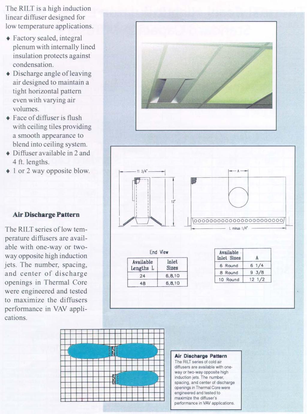
13 The HILT is a high induction linear diffuser designed for low temperature applications. Factory sealed, integral plenum with internally lined insulation protects against condensation. Discharge angle of leaving air designed to maintain a tight horizontal pattern even with varying air volumes. Molded face of diffuser has smooth curved appearance to blend into ceiling system. Diffuser available in 2 and 4 ft. lengths. or 2 way opposite blow. Air Discharge Pattern The HILT series of low temperature diffusers are available with one-way or two-way opposite high induction jets. The number, spacing, and center of discharge openings in Thermal Core were engineered and tested to maximize the diffusers performance in VAV applications. 2
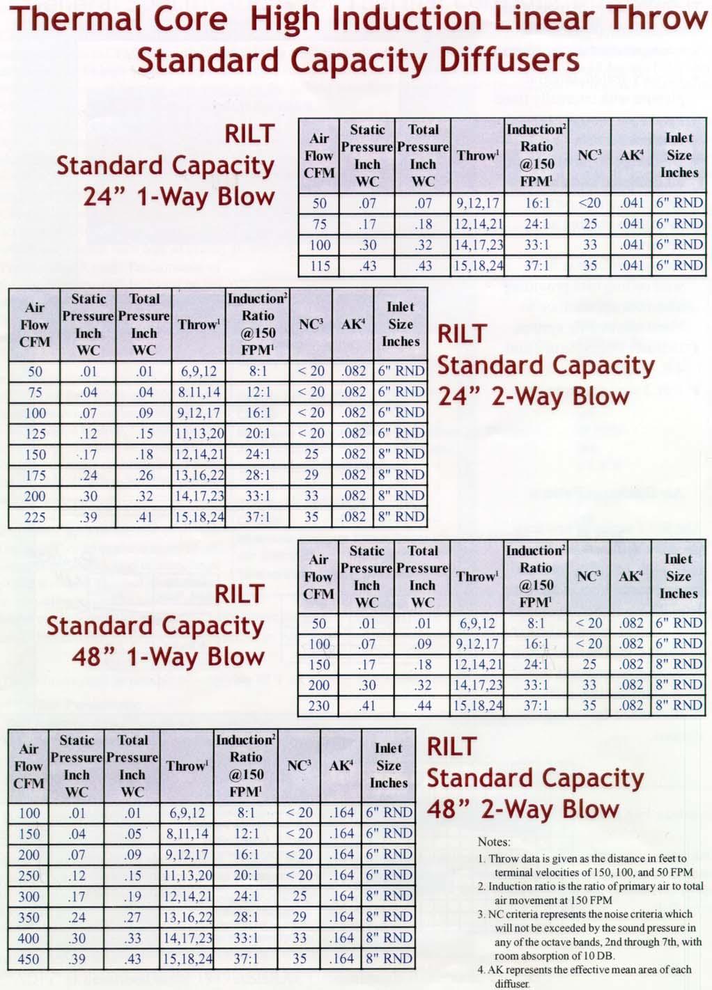
14 Thermal Core High Induction Linear Throw Standard Capacity Diffusers HILT Standard Capacity 24 -Way Blow Air Flow CFM Static Inch WC Total Inch WC Throw 2 Induction FPM NC 3 AK 4 Inle t Size Inches ,2,7 6: ,4,2 24: ,7,23 33: ,8,24 37: Air Flow CFM Static Inch WC Total Inch WC Throw 2 Induction FPM NC 3 AK 4 Inle t Size Inches ,9,2 8: ,4 2: ,2,7 6: ,3,20 20: ,4,2 24: ,6,22 28: ,7,23 33: ,8,24 37: HILT Standard Capacity 24 2-Way Blow HILT Standard Capacity 48 -Way Blow Air Flow CFM Static Inch WC Total Inch WC Throw 2 Induction FPM NC 3 AK 4 Inle t Size Inches ,9,2 8: ,2,7 6: ,4,2 24: ,7,23 33: ,8,24 37: Air Flow CFM Static Inch WC Total Inch WC Throw 2 Induction FPM NC 3 AK 4 Inle t Size Inches ,9,2 8: ,,4 2: ,2,7 6: ,3,20 20: ,4,2 24: ,6,22 28: ,7,23 33: ,8,24 37: HILT Standard Capacity 48 2-Way Blow Notes:. Throw data is given as the distance in feet to terminal velocities of 50, 00, and 50 FPM 2. Induction ratio is the ratio of primary air to total air movement at 50 FPM 3. NC criteria represents the noise criteria which will not be exceeded by the sound pressure in any of the octave bands, 2nd through 7th, with room absorption of 0 DB. 4. AK represents the effective mean area of each diffuser. 3
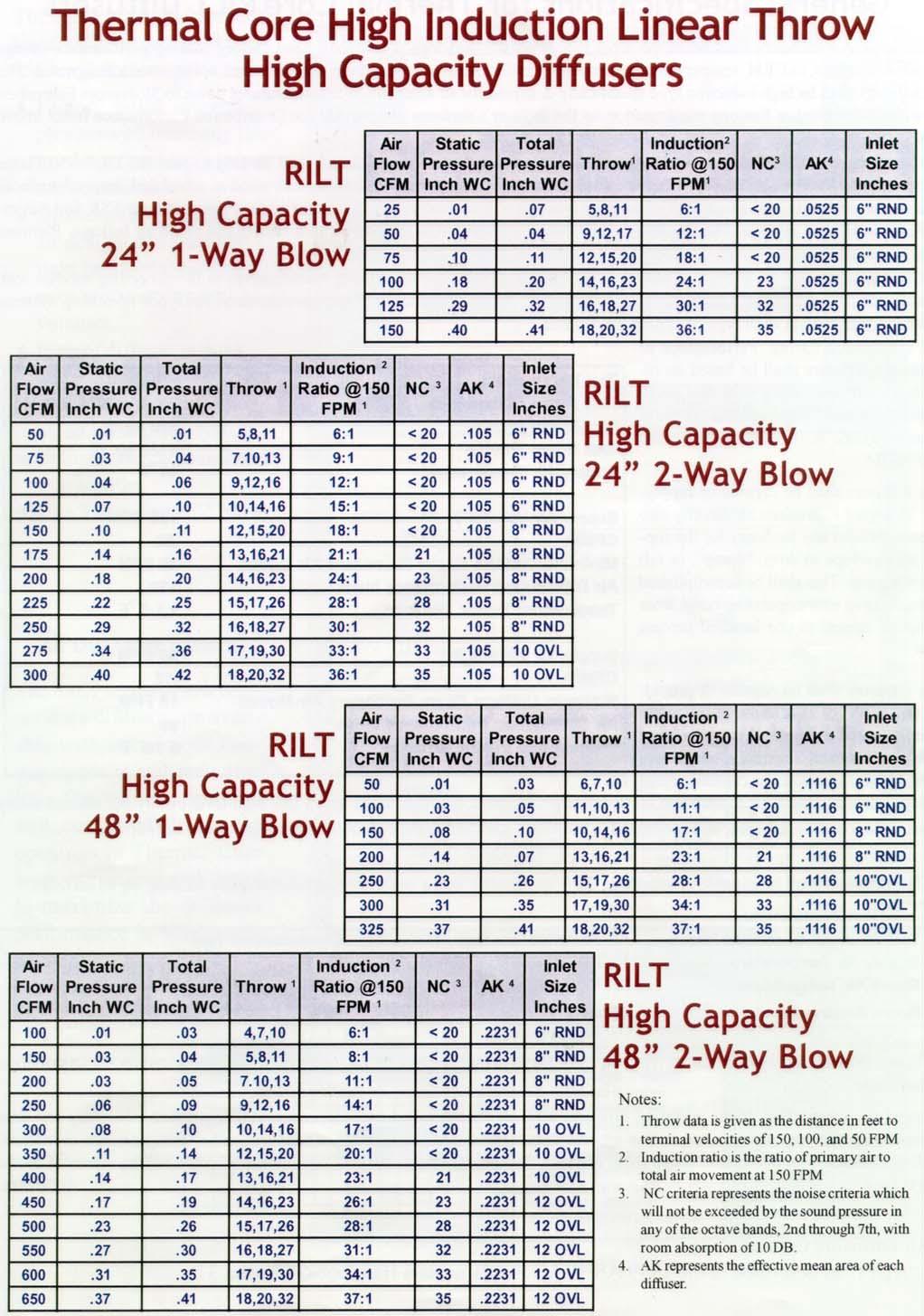
15 Thermal Core High Induction Linear Throw High Capacity Diffusers HILT High Capacity 24 -Way Blow Air Flow CFM Static Inch WC Total Inch WC Throw 2 Induction FPM NC 3 AK 4 Inlet Size Inches ,8, 6: ,2,7 2: ,5,20 8: ,6,23 24: ,8,27 30: ,20,32 36: Air Flow CFM Static Inch WC Total Inch WC Throw 2 Induction FPM Inlet NC 3 AK 4 Size Inches ,8, 6: ,3 9: ,2,6 2: ,4,6 5: ,5,20 8: ,6,2 2: ,6,23 24: ,7,26 28: ,8,27 30: ,9,30 33: OVL ,20,32 36: OVL HILT High Capacity 24 2-Way Blow Air Flow CFM HILT High Capacity 48 -Way Blow Static Inch WC Total Inch WC Throw Air Flow CFM 2 Induction FPM Static Inch WC Inlet NC 3 AK 4 Size Inches ,7,0 6: ,8, 8: ,3 : ,2,6 4: ,4,6 7: OVL ,5,20 20: OVL ,6,2 23: OVL ,6,23 26: OVL ,7,26 28: OVL ,8,27 3: OVL ,9,30 34: OVL ,20,32 37: OVL 4 Total Inch WC Throw 2 Induction FPM Inlet NC 3 AK 4 Size Inches ,7, 0 6: ,0, 7 3 : ,4,6 7: ,6,2 23: ,7,26 28: "OVL ,9,30 34: "OVL ,20,32 37: "OVL HILT High Capacity 48 2-Way Blow Notes:. Throw data is given as the distance in feet to terminal velocities of 50, 00, and 50 FPM 2. Induction ratio is the ratio of primary air to total air movement at 50 FPM 3. NC criteria represents the noise criteria which will not be exceeded by the sound pressure in any of the octave bands, 2nd through 7th, with room absorption of 0 DB. 4. AK represents the effective mean area of each diffuser.
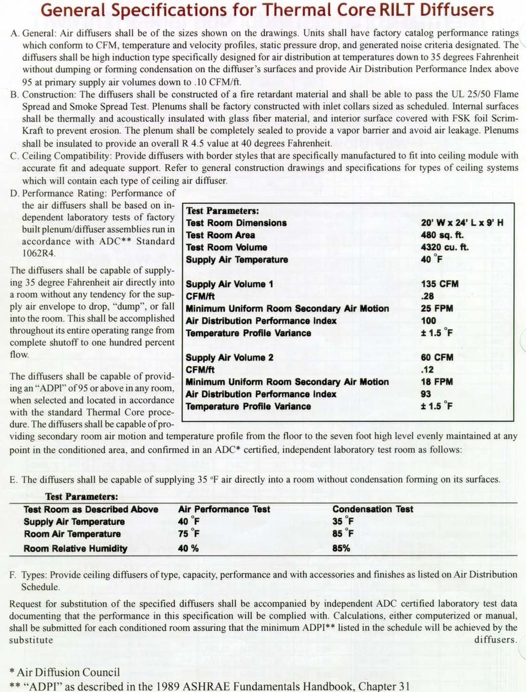
16 General Specifications for Thermal Core HILT Diffusers A. General: Air diffusers shall be of the sizes shown on the drawings. Units shall have factory catalog performance ratings which conform to CFM, temperature and velocity profiles, static pressure drop, and generated noise criteria designated. The diffusers shall be high induction type specifically designed for air distribution at temperatures down to 35 degrees Fahrenheit without dumping or forming condensation on the diffuser s surfaces and provide Air Distribution Performance Index above 95 at primary supply air volumes down to.0 CFM/ft. B. Construction: The diffusers shall be constructed of a fire retardant material and shall be able to pass the UL 25/50 Flame Spread and Smoke Spread Test. Plenums shall be factory constructed with inlet collars sized as scheduled. Internal surfaces shall be thermally and acoustically insulated with glass fiber material, and interior surface covered with FSK foil Scrim- Kraft to prevent erosion. The plenum shall be completely sealed to provide a vapor barrier and avoid air leakage. Plenums shall be insulated to provide an overall R 4.5 value at 40 degrees Fahrenheit. C. Ceiling Compatibility: Provide diffusers with border styles that are specifically manufactured to fit into ceiling module with accurate fit and adequate support. Refer to general construction drawings and specifications for types of ceiling systems which will contain each type of ceiling air diffuser. D. Performance Rating: Performance of the air diffusers shall be based on independent laboratory tests of factory Test Room Dimensions 20 W x 24 L x 9 H Test Parameters: built plenum/diffuser assemblies run Test Room Area 480 sq. ft. in accordance with ADC** Standard Test Room Volume 4320 cu. ft. 062R4. Supply Air Temperature 40 o F The diffusers shall be capable of supplying 35 degree Fahrenheit air directly into a room without any tendency for the supply air envelope to drop, dump, or fall into the room. This shall be accomplished throughout its entire operating range from complete shutoff to one hundred percent flow. The diffusers shall be capable of providing an ADPl of 95 or above in any room, when selected and located in accordance with the standard Thermal Core procedure. The diffusers shall be capable of Supply Air Volume 35 CFM CFM/ft.28 Minimum Uniform Room Secondary Air Motion 25 FPM Air Distribution Performance Index 00 Temperature Profile Variance ±.5 o F Supply Air Volume 2 60 CFM CFM/ft.2 Minimum Uniform Room Secondary Air Motion 8 FPM Air Distribution Performance Index 93 Temperature Profile Variance ±.5 o F providing secondary room air motion and temperature profile from the floor to the seven foot high level evenly maintained at any point in the conditioned area, and confirmed in an ADC* certified, independent laboratory test room as follows: E. The diffusers shall be capable of supplying 35 o F air directly into a room without condensation forming on its surfaces. Test Parameters: Test Room as Described Above Air Performance Test Condensation Test Supply Air Temperature 40 o F 35 o F Room Air Temperature 75 o F 85 o F Room Relative Humidity 40 % 85% F. Types: Provide ceiling diffusers of type, capacity, performance and with accessories and finishes as listed on Air Distribution Schedule. Request for substitution of the specified diffusers shall be accompanied by independent ADC certified laboratory test data documenting that the performance in this specification will be complied with. Calculations, either computerized or manual, shall be submitted for each conditioned room assuring that the minimum ADPI** listed in the schedule will be achieved by the substitute diffusers. * Air Diffusion Council ** ADPI as described in the 989 ASHRAE Fundamentals Handbook, Chapter 3 5

17 Model OMNI-LT High Induction Thermal Core Cold Air Diffuser Model OMNI-LT High Induction U.S. Patent No. 4,876,949 Canadian patent No. 63,76 The OMNI-LT is designed for low temperature applications. This diffuser combines a strong unobtrusive appearance with exceptional performance. The patented Thermal Core generates a high velocity jet that maximizes induction of room air. The curved, molded shape of the backpan combines with the airfoil discharge edge of the face panel to provide a tight horizontal pattern. The face panel is constructed from 8 gauge steel. The formed edges of the face assures a straight and level surface. The backpan is factory sealed with /2 thick insulation with a vapor barrier which protects against moisture forming in unconditioned plenum space. The face panel is held in place by steel rods that lock into backpan. The panel can be removed from the backpan. Material is heavy guage steel (8 guage in the face panel). Ceiling Module A Nominal Round Duct size B C D 6, 8 /4 3 3 / /8 3 7 /8 24 x 24 2 x 2 /4 3 3 /4 E
18 Thermal Core OMNI-LT High Induction Diffusers * * * Air Flow CFM Static Inch WC Total Inch WC Blow Throw Pattern 2 Induction FPM Inlet NC 3 AK 4 Size Inches ,7, 2-Way 5: ,8,2 2-Way 22: ,,5 2-Way 29: ,8,2 4-Way 8: ,8,2 4-Way 22: ,9,4 4-Way 25: ,,5 4-Way 29: ,0,4 4-Way 33: RND ,,5 4-Way 36: RND * Available in 2 x 2, in 4-way blow only. Notes:. Throw data is given as the distance in feet to terminal velocities of 50, 00, and 50 FPM 2. Induction ratio is the ratio of primary air to total air movement at 50 FPM 3. NC criteria represents the noise criteria which will not be exceeded by the sound pressure in any of the octave bands, 2nd through 7th, with room absorption of 0 DB. 4. AK represents the effective mean area of each diffuser. 7


19 Thermal Core Cold Air Perforated Diffuser Model PSS-LT High Induction U.S. Patent No. 4,876,949 Canadian patent No. 63,76 The PSS-LT is designed for cold air applications. The patented Thermal Core generates a high velocity jet that maximizes the room induction rate. Factory sealed plenum with internally lined insulation. Condensation guard on back pan protects against moisture forming in unconditioned plenum space. Backpan design to provide tight horizontal discharge pattern even in VAV applications. Four-way discharge pattern optimizes induction rate and throw to maintain maximum comfort in occupied zone. Face is removable allowing access to Thermal Core. Perforated face has 3/6 diameter holes on /4 staggered centers. Inlet collar (neck) has ample depth for easy duct connection. Ceiling Module A 24 x 24 Nominal Round Duct size B C D 6, 8 /4 3 3 / /8 3 7 /8 2 x 2 /4 3 3 /4 Material: Heavy gauge steel backpan molded Thermal Core, steel perforated face. Standard Finish: #26 white 8


20 Thermal Core High Induction PSS-LT Diffusers * * * * Available in 2 x 2, in 4-way blow only. Notes:. Throw data is given as the distance in feet to terminal velocities of 50, 00, and 50 FPM 2. Induction ratio is the ratio of primary air to total air movement at 50 FPM 3. NC criteria represents the noise criteria which will not be exceeded by the sound pressure in any of the octave bands, 2nd through 7th, with room absorption of 0 DB. 4. AK represents the effective mean area of each diffuser. Public television station control room. 9
21 General Specifications for Thermal Core OMNI-LT Diffusers A. General: Air diffusers shall be of the sizes shown on the drawings. Units shall have factory catalog performance ratings which conform to CFM, temperature and velocity profiles, static pressure drop, and generated noise criteria designated. The diffusers shall be high induction type specifically designed for air distribution at temperatures down to 35 degrees Fahrenheit without dumping or forming condensation on the diffuser s surfaces and provide Air Distribution Performance Index above 95 at primary supply air volumes down to.0 CFM/ft. B. Construction: The diffusers shall be constructed of die-formed steel with baked enamel finish. Induction core shall be constructed of a fire retardant composite material and shall be able to pass the UL 25/50 Flame Spread and Smoke Spread Test. The back-pans shall be insulated with a closed cell anti-fiber insulating material. The inlet collars shall be sized as scheduled. C. Ceiling Compatibility: Provide diffusers with border styles that are specifically manufactured to fit into ceiling module with accurate fit and adequate support. Refer to general construction drawings and specifications for types of ceiling systems which will contain each type of ceiling air diffuser. D. Performance Rating: Performance of the air diffusers shall be based on independent laboratory tests of factory Test Parameters: built plenum/diffuser assemblies run Test Room Dimensions 20 W x 24 L x 9 H in accordance with ADC** Standard Test Room Area 480 sq. ft. 062R4. Test Room Volume 4320 cu. ft. The diffusers shall be capable of supplying 35 degree Fahrenheit air directly into a room without any tendency for the supply air envelope to drop, dump, or fall into the room. This shall be accomplished throughout its entire operating range from complete shutoff to one hundred percent flow. The diffusers shall be capable of providing an ADPl of 95 or above in any room, when selected and located in accordance with the standard Thermal Core procedure. The diffusers shall be capable of providing secondary room air motion Supply Air Temperature and temperature profile from the floor to the seven foot high level evenly maintained at any point in the conditioned area, and confirmed in an ADC* certified, independent laboratory test room as follows: 40 o F Supply Air Volume 35 CFM CFM/ft.28 Minimum Uniform Room Secondary Air Motion 25 FPM Air Distribution Performance Index 00 Temperature Profile Variance ±.5 o F Supply Air Volume 2 60 CFM CFM/ft.2 Minimum Uniform Room Secondary Air Motion 8 FPM Air Distribution Performance Index 93 Temperature Profile Variance ±.5 o F E. The diffusers shall be capable of supplying 35 o F air directly into a room without condensation forming on its surfaces. Test Parameters: Test Room as Described Above Air Performance Test Condensation Test Supply Air Temperature 40 o F 35 o F Room Air Temperature 75 o F 85 o F Room Relative Humidity 40 % 85% F. Types: Provide ceiling diffusers of type, capacity, performance and with accessories and finishes as listed on Air Distribution Schedule. Request for substitution of the specified diffusers shall be accompanied by independent ADC certified laboratory test data documenting that the performance in this specification will be complied with. Calculations, either computerized or manual, shall be submitted for each conditioned room assuring that the minimum ADPI** listed in the schedule will be achieved by the substitute diffusers. * Air Diffusion Council ** ADPI as described in the 989 ASHRAE Fundamentals Handbook, Chapter 3 20


22 Thermal Imaging of Two Diffuser Types Slot Diffuser Continues to dump at 25% flow. Begins to dump at 50% flow. Diffuser performs at full flow. Thermal Core Omni-Diffuser Cold Air Flow Thermal Core Diffuser does not dump and maintains high induction down to 25% flow. 2

23 Thermal Core HCRD Downflow High Induction Diffuser Notes:. Throw data is given as the distance in feet to terminal velocities of 50, 00, and 50 FPM 2. Induction ratio is the ratio of primary air to total air movement at 50 FPM 3. NC criteria represents the noise criteria which will not be exceeded by the sound pressure in any of the octave bands, 2nd through 7th, with room absorption of 0 DB. 4. AK represents the effective mean area of each diffuser. 22
24 GENERAL SPECIFICATIONS FOR THERMAL CORE HCRD DIFFUSERS A. General: Air diffusers shall be of the sizes shown on the drawings. Units shall have factory catalog performance ratings which conform to CFM, temperature and velocity profiles, static pressure drop, and generated noise criteria designated. The diffusers shall be high induction type specifically designed for air distribution at temperatures down to 35 o F in the cooling mode and 40 o F in the heating mode without dumping or forming condensation on the diffuser s surfaces and provide Air Distribution Performance Index above 95 at primary supply air volumes down to.0 CFM/ft. B. Construction: The diffusers shall be constructed of a fire retardant material and shall be able to pass the UL 25/50 Flame Spread and Smoke Spread Test. Plenums shall be factory constructed with inlet collars sized as scheduled. Internal surfaces shall be thermally and acoustically insulated with glass fiber material, and interior surface covered with FSK foil Scrim- Kraft to prevent erosion. The plenum shall be completely sealed to provide a vapor barrier and avoid air leakage. Plenums shall be insulated to provide an overall R 4.5 value at 40 degrees Fahrenheit. C. Ceiling Compatibility: Provide diffusers with border styles that are specifically manufactured to fit into ceiling module with accurate fit and adequate support. Refer to general construction drawings and specifications for types of ceiling systems which will contain each type of ceiling air diffuser. D. Performance Rating: Performance of the air diffusers shall be based on independent laboratory tests of factory Test Parameters: Test Room Dimensions 20 W x 24 L x 9 H built plenum/diffuser assemblies run in Test Room Area 480 sq. ft. accordance with ADC** Standard Test Room Volume 4320 cu. ft. 062R4. The diffusers shall be capable of supplying 35 degree Fahrenheit air directly into a room without any tendency for the supply air envelope to drop, dump, or fall into the room. This shall be accomplished throughout its entire operating range from complete shutoff to one hundred percent flow. Supply Air Temperature The diffusers shall be capable of providing an ADPl of 95 or above in any room, when selected and located in accordance with the standard Thermal Core procedure. The diffusers shall be capable of providing secondary room air motion and temperature profile from the floor to the seven foot high level evenly maintained at any point in the conditioned area, and confirmed in an ADC* certified, independent laboratory test room as follows: 40 o F Supply Air Volume 35 CFM CFM/ft.28 Minimum Uniform Room Secondary Air Motion 25 FPM Air Distribution Performance Index 00 Temperature Profile Variance ±.5 o F Supply Air Volume 2 60 CFM CFM/ft.2 Minimum Uniform Room Secondary Air Motion 8 FPM Air Distribution Performance Index 93 Temperature Profile Variance ±.5 o F E. The diffusers shall be capable of supplying 35 o F air directly into a room without condensation forming on its surfaces. Test Parameters: Test Room as Described Above Air Performance Test Condensation Test Supply Air Temperature 40 o F 35 o F Room Air Temperature 75 o F 85 o F Room Relative Humidity 40 % 85% F. Types: Provide ceiling diffusers of type, capacity, performance and with accessories and finishes as listed on Air Distribution Schedule. Request for substitution of the specified diffusers shall be accompanied by independent ADC certified laboratory test data documenting that the performance in this specification will be complied with. Calculations, either computerized or manual, shall be submitted for each conditioned room assuring that the minimum ADPI** listed in the schedule will be achieved by the substitute diffusers. * Air Diffusion Council ** ADPI as described in the 989 ASHRAE Fundamentals Handbook, Chapter 3 23

25 HCRH High Capacity Horizontal Air Flow CFM/hole Static Inch W.C. Throw Induction 50 FPM 2 NC 3 AK ,7,0 6: ,0,3 : ,4,6 7: ,6,2 23: ,7,26 28: ,9,30 34: ,20,32 37: Notes:. Throw data is given as the distance in feet to terminal velocities of 50, 00, and 50 FPM. 2. Induction ratio is the ratio of primary air to total air movement at 50 FPM 3. NC criteria represents the noise criteria which will not be exceeded by the sound pressure in any of the octave bands, 2nd through 7th, with room absorption of 0 DB. 4. AK represents the effective mean area of each diffuser. To determine overall diffuser AK multiply.0022 x dry of holes. One hole per square inch of face area - i.e x 2 = 576 holes. Minimum height = 4 : Maximum height = 2 Minimum width = 2 : Maximum width = 48 Contact factory for larger sizes. 24
26 GENERAL SPECIFICATIONS FOR THERMAL CORE HCRH DIFFUSERS A. General: Air diffusers shall be of the sizes shown on the drawings. Units Shall have factory catalog performance ratings which conform to CFM, induction ratios, temperature and velocity profiles, static pressure drop, and generated noise criteria designated. The diffusers shall be high induction type specifically designed for air distribution at temperatures down to 35 degrees Fahrenheit in the cooling mode and 40 degrees Fahrenheit in the heating mode without dumping or forming condensation on the diffuser s surfaces and provide Air Distribution Performance Index above 95 at primary supply air volumes down to.0 CFM(ft. B. Construction: The diffusers shall be constructed of a fire retardant material and shall be able to pass the UL 25/50 Flame Spread and Smoke Spread Test.. C. Mounting Frames: Frames shall be constructed of extruded aluminum suitable for mounting in a hard-wall or directly to ducts. D. Performance Rating: Performance of the air diffusers shall be based on independent laboratory tests of factory built diffuser assemblies run in accordance with ADC** Standard 062R4. The diffusers shall be capable of supplying 35 degree Fahrenheit cooling mode or 40 degrees Fahrenheit in the heating mode air directly into a room without any tendency for the supply air envelope to enter the occupied area of the room. This shall be accomplished throughout its entire operating range from complete shutoff to one hundred percent flow. The diffusers shall be capable of providing an ADPI of 95 or above in any room, when selected and located in accordance with the standard thermal core procedure. The diffusers shall be capable of providing secondary room air motion and temperature profile from the floor to the seven foot high level evenly maintained at any point in the conditioned area. E. The diffusers shall be capable of supplying 35 o F air directly into a room without condensation forming on its surfaces. Test Parameters: Test Room as Described Above Air Performance Test Condensation Test Supply Air Temperature 40 o F 35 o F Room Air Temperature 75 o F 85 o F Room Relative Humidity 40 % 85% F. Types: Provide ceiling diffusers of type, capacity, performance and with accessories and finishes as listed on Air Distribution Schedule. Request for substitution of the specified diffusers shall be accompanied by independent ADC certified laboratory test data documenting that the performance in this specification will be complied with. Calculations, either computerized or manual, shall be submitted for each conditioned room assuring that the minimum ADPI** listed in the schedule will be achieved by the substitute diffusers. 25


27 MCI Springfield, Missouri provides high indoor air quality for its employees by choosing thermal core direct jet induction diffusers. Andy Williams Theatre, Branson, Missouri, solves a tough heating, cooling, and humidity challenge by utilizing thermal core direct jet induction diffusers and cold air distribution. Results! Excellent occupant comfort. Evangel College provides an excellent study environment by applying thermal core diffusing and cold air distribution to insure high indoor air quality. St. John s Breech Medical Center, Lebanon, Missouri chooses Thermal Core diffusers and cold air distribution to insure high indoor air quality and humidity control. 26


28 The new state of the art Bone and Joint Center at Cox Hospital Springfield, Missouri applied cold air distribution and ThermalCore Diffuser to insure an ADPI of 95%. The RILT was utilized exclusively through out the entire building. Shoji Tabuchi Theater, Branson, Missouri also utilized cold air distribution to maintain an excellent comfort level. ThermalCore diffusers were used to delivery this low temperature air directly into the theater. College of the Ozarks used cold air distribution and used TermalCore diffusers to deliver this low temperature air in their state of the art training facility. ThermalCore diffuser blended into the unique architectural ceiling. 27
29 THERMAL CORE DIFFUSER SELECTION AND LOCATION ) Select diffusers for 80 to 00 percent of their nominal air flow rating. 2) Deactivate nozzles if necessary. 3) Diffuser Location: a) Air stream from opposing diffusers should not collide at greater than 50 FPM air velocity. b) Air stream from diffusers should meet adjacent walls between 50 to 500 FPM air velocity. c) Diffusers should be placed so that the lateral distance between a diffuser and the wall is the diffuser s throw (in feet) at 50 FPM terminal velocity times 0.404, or less. The lateral distance between adjacent diffusers is the diffuser s throw at 50 FPM terminal velocity times 0.808, or less. Diffuser Throw Drawings The following sequence illustrates some of the more common errors made in air-distribution design. The first four cases show stagnation, turbulence, and over-sized diffuser selection leading to low induction ratio. Case 5 illustrates the principles behind proper placement of diffusers. All cases apply to a typical,0 ft 2 classroom with a total air flow of 450 cfm. 28
30 Case. A single HILT-48" 2-way Induction Ratio 37: ADPI = <85 due to stagnant area Case 2. Two HILT-48" -way Induction Ratio 37: ADPI = <85 due to stagnant area Case 3. Two HILT-24" 2-way (Perpendicular configuration) Induction Ratio 37: ADPI = <70 due to stagnant area and turbulent downwash Case 4. Two HILT-48" 2-way Induction Ratio 20: ADPI = <90 due to low induction ratio. (ADPI will decrease further if air-supply throttles.) Case 5. Two HILT-24" 2-way (Parallel Configuration) Induction Ratio 37: ADPI = 00 due to proper selection 29
31 30
32 3
33 Thermal Core, Inc. P.O. Box 55 Springfield, MO 6580 (47) Fax (47) (Rev. 6/05)
Displacement Ventilation
 Displacement Ventilation Displacement Ventilation Displacement Ventilation vs. Dilution Ventilation Characteristics Design Considerations Layout and Selection Product Overview Casino Case Study Dilution
80-6-ISD A Better Solution for Proper Space Air Distribution
 Air Handling Systems Engineering & Technical Bulletin 80-6-ISD A Better Solution for Proper Space Air Distribution In designing an HVAC system, an engineer has the following goals: 1. True building load
ASHRAE JOURNAL ON REHEAT
 Page: 1 of 7 ASHRAE JOURNAL ON REHEAT Dan Int-Hout Chief Engineer Page: 2 of 7 Overhead Heating: A lost art. March 2007 ASHRAE Journal Article Dan Int-Hout Chief Engineer, Krueger VAV terminals provide
AIR DISTRIBUTION. C. Section Building Automation and Control System Guidelines. D. Section Fire Alarm System & Detection Systems
 233100 AIR DISTRIBUTION PART 1: GENERAL 1.01 RELATED SECTIONS A. Section 230700 HVAC Insulation B. Section 237300 Air Handling C. Section 230900 Building Automation and Control System Guidelines D. Section
Units for suspended ceilings Type DID632
 Type with hinged induced air grille water connections Active chilled beam with two-way air discharge and horizontal heat exchanger in lengths from to 0 feet Active chilled beam for heating and cooling,
UFAD and Displacement Ventilation. Dan Int-Hout, FASHRAE Chief Engineer Krueger Richardson, Texas
 UFAD and Displacement Ventilation Dan Int-Hout, FASHRAE Chief Engineer Krueger Richardson, Texas UFAD and DV Systems, Objectives: Understand Differences between: Well Mixed, Partially Stratified and Fully
KLIMA Active Chilled Beams
 KLIMA 2 600 Active Chilled Beams Index Subject Page Index 1 Introduction 2 General description 3-4 Product features 5-6 Dimensions 7 Performance data 8-11 Section example Guide specifications 13 1 Introduction
Engineering Guide VAV Diffusers. Please refer to the Price Engineer s HVAC Handbook for more information on VAV Diffusers.
 VAV Diffusers lease refer to the rice Engineer s HVAC Handbook for more information on VAV Diffusers. Diffuser Types Ceiling Diffusers Conventional air distribution systems typically group several rooms
Inffusers. idl20 (2 WAY) ids60 (4 WAY)
 ids60 (4 WAY)") Inffusers idl20 (2 WAY) ids60 (4 WAY) built on innovation what is an inffuser? DADANCO s INFFUSERS are quite simply an induction diffuser that uses special nozzles located in the underside of the air plenum
Inffusers idl20 (2 WAY) ids60 (4 WAY) built on innovation what is an inffuser? DADANCO s INFFUSERS are quite simply an induction diffuser that uses special nozzles located in the underside of the air plenum
IDL20e (2 way discharge) IDS60e (4 way discharge) Inffusers. UDI (vertical discharge) Frequently Asked Questions
 IDS60e (4 way discharge) Inffusers. UDI (vertical discharge) Frequently Asked Questions") IDL20e (2 way discharge) IDS60e ( way discharge) Frequently Asked Questions UDI (vertical discharge) Inffusers INFFUSER FREQUENTLY ASKED QUESTIONS The following are frequently asked questions (FAQ s) on
IDL20e (2 way discharge) IDS60e ( way discharge) Frequently Asked Questions UDI (vertical discharge) Inffusers INFFUSER FREQUENTLY ASKED QUESTIONS The following are frequently asked questions (FAQ s) on
THERMA FUSER SIDEWALL LINEAR VAV DIFFUSER
 THE ELW INTEROPERABLE THERMA FUSER SIDEWALL LINEAR VAV DIFFUSER FORM 56.1 REV 0707 SPECIFICALLY DESIGNED FOR INTEROPERABILITY The ELW provides more information about what s happening in the space than
Space Air Diffusion II
 MEBS6008 Environmental Services II http://me.hku.hk/bse/mebs6008/ Space Air Diffusion II Ir. Dr. Sam C. M. Hui Visiting Assistant Professor Department of Mechanical Engineering The University of Hong Kong
Modular Active. Chilled. Beams
 Modular Active Chilled Beams How Twa MAC Beams Work Primary air (100% outside air) is dehumidified to between 50-57 F dew point and is used to: control the latent requirements of the space, provide fresh
Chilled Water DOAS Fan Powered Terminal Units
 Chilled Water DOAS Fan Powered Terminal Units CHILLED WATER DOAS FAN POWERED TERMINAL UNITS DOAS TERMINAL UNITS FEATURES AND BENEFITS MINIMUM VENTILATION CONTROL The DOAS unit provides the Designer, Owner
Active Chilled Beams
 T 2.4/12/US/7 Active Chilled Beams DID61 and DID62 series TROX USA, Inc. 405 Settingdown Circle www.troxusa.com Cumming, GA 0028 e-mail trox@troxusa.com Telephone 770.569.14 Facsimile 770.569.14 Contents
DFE T ECHNOLOGY. At Conceptronic, the design and management process for reflow soldering systems is called Dynamic Flow Engineering, or DFE.
 DFE T ECHNOLOGY As components become smaller, component mixes become more diverse, and board densities continue to increase, the processes of packaging, interconnection, and assembly are challenging the
FAN TERMINAL UNITS Constant Volume (Series Flow), Standard Design
, Standard Design") FAN TERMINAL UNITS Constant Volume (Series Flow), Standard Design Fan motor (PSC or ECM). UL Listed 1 insulation conforms to UL Test 181 and NFPA 90A. Plenum air filter rack. (Filter Optional) Casing has
FAN TERMINAL UNITS Constant Volume (Series Flow), Standard Design Fan motor (PSC or ECM). UL Listed 1 insulation conforms to UL Test 181 and NFPA 90A. Plenum air filter rack. (Filter Optional) Casing has
SINGLE DUCT TERMINAL UNITS
 Performance Data AHRI Certification and Performance Notes Model Series 3000 asic Unit AHRI Certification Rating Points VAV: Fiberglass Inlet Size Airflow cfm l/s Min. Inlet Ps w.g. Pa Discharge Sound Power
A. Air Handling Units shall be designed to the specific requirements of the application: Recirculation or 100% Makeup.
 SECTION 23 70 00- CENTRAL HVAC EQUIPMENT PART 1: GENERAL 1.1 PURPOSE: A. This standard is intended to provide useful information to the Professional Service Provider (PSP) to establish a basis of design.
Don t Turn Active Beams Into Expensive Diffusers
 This article was published in ASHRAE Journal, April 2012. Copyright 2012 American Society of Heating, Refrigerating and Air-Conditioning Engineers, Inc. Posted at www.ashrae.org. This article may not be
Rosemex Products 96 VENTILATION CLIMATAIR COMPARTMENT AIR HANDLING UNITS
 10 Rosemex Products 96 VENTILATION CLIMATAIR COMPARTMENT AIR HANDLING UNITS 2 INDEX Page Description - Introduction -Application - Data... 2 Typical Installation... 3 Sound performance... 3-6 Dimensional
Technical Selection. elevent ceiling diffusers. Swirl, Jet, Louvred and Curved ceiling diffusers
 elevent ceiling diffusers Technical Selection Swirl, Jet, Louvred and Curved ceiling diffusers Paltech elevent Ceiling Diffusers are protected by: Australian Patent 0179430 + other patents pending Australian
Chilled Beam/Induction Unit
 For the energy efficient buildings of today and tomorrow Chilled Beam/Induction Unit All Way Blow Chilled Beam Technical Specifications American Owned and Operated Chilled Beam/Induction Unit A Chilled
ARE BETTER THAN VAV BOXES Lowest energy VAV terminal Easily adapts to office layout change Lowest cost per zone of control
 S FORM 2.1/402 HRMA-FUSR VAV MODULS AR BR HAN VAV BOXS Lowest energy VAV terminal asily adapts to office layout change Lowest cost per zone of control Superior air distribution Low to no maintenance ystems
TLW Therma-Fuser Linear Sidewall Thermally Powered VAV Diffuser
 TLW Therma-Fuser Linear Sidewall Thermally Powered VAV Diffuser Therma-Fuser Systems Models: TLW-C VAV cooling only TLW-CW VAV cooling with constant volume warm up TLW-D Manually adjustable blades TLW-RAD
DESCRIPTION OF TECHNOLOGY
 March 2009 Underfloor Air Distribution INTRODUCTION Copyright 2009 Glumac. All rights reserved. While this Green Paper discusses primarily the use of raised access floors for air distribution, HVAC integration
Underfloor Air Distribution:
 Underfloor Air Distribution: An underfloor air distribution system utilizes a plenum space between the structural slab and the underside of a raised floor to distribute the conditioned air to the room.
Linear Floor Heaters
 Linear Floor Heaters The Price Linear Floor Heater family provides ultimate flexibility in terms of style, performance, and ease of installation. Using room-side heat virtually eliminates the requirement
CUMULUS CUMULUS. Key figures. Construction. Function Integrated chilled beams
 Integrated chilled beams Key figures Connections: 1x mm, 2x mm Airflow: 5-60 l/s Pressure range: 40 - Pa Size: 293 x 200 mm (WxH) Length: 1192 or 1792 mm Total effect: up to 1200W Cumulus is available
PRODUCTS TAO TAO PRODUCT: ADVANCING THE SCIENCE OF AIR DISTRIBUTION. temperature ambient optimizer. Redefine your comfort zone.
 A I R D I S T R I B U T I O N PRODUCTS PRODUCT: TAO TAO temperature ambient optimizer F O C U S 04 ADVANCING THE SCIENCE OF AIR DISTRIBUTION Redefine your comfort zone. www.titus-hvac.com Rethink what
Jim Aswegan Chief Engineer
 Displacement Ventilation Jim Aswegan Chief Engineer Displacement Ventilation Systems Comfort & Contaminate Control DV Concepts & System Benefits Outlet Types and Air Patterns Example l Space Layouts Displacement
HAP e-help. Modeling Induction Beams in HAP v4.8 QB TIP 001
 This HAP e-help provides a high-level overview of induction beams, how they work and how to model them in HAP 4.8 (and later versions). The first half of the article explains how induction beams work.
Energy Conservation with PARAG Energy Efficient Axial Flow FRP Fans
 PARAG FANS & COOLING SYSTEMS LTD. Energy Conservation with PARAG Energy Efficient Axial Flow FRP Fans Registered Office & Works Plot No.1/2B & 1B/3A, Industrial Area No.1 A.B.Road, Dewas 455001 (M.P.)
HVAC Optimization with Cold Air Distribution
 PDHonline Course M186 (2 PDH) HVAC Optimization with Cold Air Distribution Instructor: A. Bhatia, B.E. 2012 PDH Online PDH Center 5272 Meadow Estates Drive Fairfax, VA 22030-6658 Phone & Fax: 703-988-0088
Brown University Revised August 3, 2012 Facilities Design & Construction Standards SECTION AIR HANDLING UNITS
 SECTION 23 70 00 AIR HANDLING UNITS PART 1. GENERAL 1.1 Section includes air-handling units to 15,000 cfm and accessories. 1.2 Related Sections 1 : A. Division 01 - Brown University Standard for Narragansett
Grilles & Diffusers - Metal
 Therma-Fuser Product Code Face Size Metric Inlet Designation Imperial 16040 595 x 595 6 16041 595 x 595 8 16042 595 x 595 10 16043 595 x 595 12 Grilles are white. Therma-Fuser is thermal vav diffuser with
ENGINEERING BULLETIN. Overview of Chilled Beam Technology. Purpose. Summary. Theory
 Overview of Chilled Beam Technology Purpose Chilled beam technology is new to the United States but has been used in Europe since the 1950 s. Chilled beams can reduce energy costs, improve indoor air quality,
SECTION AIR DUCT ACCESSORIES
 SECTION 23 33 00 AIR DUCT ACCESSORIES PART 1 - GENERAL 1.1 SUMMARY A. Section includes back-draft dampers, combination fire-and-smoke dampers, duct access doors, fire dampers, smoke dampers, volume control
Therma-Fuser Square Thermally Powered VAV Diffuser
 ST Therma-Fuser Square Thermally Powered VAV Diffuser Therma-Fuser Systems Models: ST-HC Separate set points for VAV heating and VAV cooling ST-C One set point for VAV cooling only ST: Product Overview
VCD,VRD,VSD 4/5 GREEN TEMPERATURE OFFSET FOR WINTER HEATING AND COOLING CHANGEOVER MECHANICAL THERMAL MECHANISM
 THERMAL VARIABLE VOLUME CEILING DIFFUSER 6 VCD,VRD,VSD 4/5 GREEN TEMPERATURE OFFSET FOR WINTER HEATING AND COOLING CHANGEOVER EXCELLENT THROW & FLOW MECHANICAL THERMAL MECHANISM LOW NOISE HIGH INDUCTION
Air Management and Energy Savings with
 Air Management and Energy Savings with High Efficiency HVAC Diffusers & Tubes Manufactured in Canada Developed in Germany with advancements of North America by 40 years expertise, our product architectural
SECTION DUCTWORK
 SECTION 15890 DUCTWORK PART 1 GENERAL 1.01 SUMMARY A. Related Sections: 1. 07270 - Firestopping and Fire and Smoke Barrier Caulking. 2. 15260 - Vibration Isolation. 3. 15280 - Thermal Insulation (HVAC).
UNDERFLOOR PRODUCTS E3
 UNDERFLOOR PRODUCTS E3 Introduction Introduction Changes in office space usage, sustainable design, and indoor air quality issues have sparked considerable interest in the application of supplying conditioned
Better Air Dispersion for. Underfloor. Plenums
 Better Air Dispersion for Underfloor Plenums Uniform Air Mixing for UFAD Plenums Inlet Connection Zippered inlet collar secures to metal using DuctBelt and Anchor UFAD Technology UnderFloorSox (UFSoxTM)
Gas-Fired Unit Heaters Commercial & Industrial
 6-107.10 February, 2005 Gas-Fired Unit Heaters Commercial & Industrial GRAVITY VENTED PD, BD POWER VENTED PDP, BDP, HD SEPARATED COMBUSTION PSH, BSH, HDS GAS-FIRED, GRAVITY-VENTED UNIT HEATERS Low Initial
Low Profile Layout Guidelines
 Low Profile Layout Guidelines Open circuit cooling towers, closed circuit cooling towers, and evaporative condensers all depend upon an adequate supply of fresh, ambient air to provide design capacity.
A REASONABLE ALTERNATIVE TO CHILLED BEAMS Dan Int-Hout Chief Engineer
 Page: 1 of 6 A REASONABLE ALTERNATIVE TO CHILLED BEAMS Dan Int-Hout Chief Engineer The DOAS Fan Powered Terminal Unit Page: 2 of 6 ASHRAE is advocating that energy use in buildings be reduced 30% below
CB18/CBS18 Bulletin # September 1994 Supersedes August 1986
 ENGINEERING DATA CB18 SERIES UP-FLOW CBS18 SERIES HORIZONTAL 2 To 5 Ton (7 To 18 kw) Nominal Cooling Capacity 7200 To 102 400 Btuh (2.1 To 30.0 kw) Optional Electrical Heat ENGINEERING DATA COILS MATCHED
Active Chilled Beams. Technical Data Bulkhead-Mounted Concealed Model With Horizontal Coil and Auxiliary Drain Pan
 Active Chilled Beams ACB10 Bulkhead-Mounted Concealed (Horizontal discharge) Technical Data Bulkhead-Mounted Concealed Model With Horizontal and Auxiliary Drain Pan APPLICATION CONSIDERATIONS The general
Unico Training. Class for R E Michel Salesmen
 Class for R E Michel Salesmen Outlet (UPC-56B) Sound Attenuator (UPC-26C) Elbow Plenum Supply Tubing (UPC-25) Blower Modules (2430,3642, 4860) Heating Module (MH2430, MH3660) Cooling Modules (MC2430, MC3642,
ADRIATIC VF. Active chilled beam with cooling, heating and ventilation QUICK FACTS
 Active chilled beam with cooling, heating and ventilation QUICK FACTS The ADRIATIC VF is a chilled beam with integrated recirculated air opening in the face plate. Air is discharged into the room along
Polaris-I-60. active chilled beam. the future of space conditioning
 the future of space conditioning Polaris-I-60 active chilled beam Function Cooling and supply air with two-way air distribution Available with heating and integrated controls Application Offices, hotels,
AIR HANDLERS. Central Station (CS3) Roof Mounted (RT) (Modular AL Frame AHU)
 Roof Mounted (RT) (Modular AL Frame AHU)") AIR HANDLERS Central Station (CS3) (Modular AL Frame AHU) Roof Mounted (RT) CONTENTS 1. CS3 Modular Aluminium Frame AHU : Unit Types 2. Casing Structure 3. Blowers and Drives 4. Coils 5. Options and Accessory
AIR HANDLERS Central Station (CS3) (Modular AL Frame AHU) Roof Mounted (RT) CONTENTS 1. CS3 Modular Aluminium Frame AHU : Unit Types 2. Casing Structure 3. Blowers and Drives 4. Coils 5. Options and Accessory
Chilled beam technology overview John Woollett 1, Jonas Åkesson 2 Swegon AB 1,2
 Chilled beam technology overview John Woollett 1, Jonas Åkesson 2 Swegon AB 1,2 john.woollett@swegon.se, jonas.akesson@swegon.se SUMMARY The main focus of the paper will be on active beam technology regarding
SECTION TESTING, ADJUSTING, AND BALANCING FOR HVAC INTRODUCTORY INFORMATION
 SECTION 15990 TESTING, ADJUSTING, AND BALANCING FOR HVAC INTRODUCTORY INFORMATION The purpose of this guide specification is to assist the Specifier in correctly specifying Mechanical System Testing Adjusting
45 Commerce Ave., Unit #2 South Burlington, VT tel: fax:
 SMAT ZONE TM VAV Electronic Diffusers SMAT ZONETM www.smartdiffuser.com SMAT ZONE SE-HC/M, Type LT, Lay-in, T-Bar, VAV Fully Modulating Diffuser Specifications APPLICATION: The Model SE-HC/M VAV Smart
DADANCO Technical Paper
 DADANCO Technical Paper 260 North Elm Street Westfield, MA 01085 Phone: (413) 564-5657 Fax: (413) 568-2969 March 2013 CLASSROOM SOLUTION USING ACTIVE CHILLED BEAMS (Note: This technical paper assumes the
AcoustiFlo Fans: Retrofit Solutions and Beyond
 AcoustiFlo Fans: Retrofit Solutions and Beyond The Most Energy Efficient Plenum Fan in the World! The AcoustiFLO Modular Fan RETROFITS Ideal for fan replacement inside any air handling unit Module is 35
COMcheck Software Version Mechanical Compliance Certificate
 COMcheck Software Version 3.8.2 Mechanical Compliance Certificate 90.1 (2007) Standard Section 1: Project Information Project Type: New Construction Project Title : Rudy's Star Motors Construction Site:
Square Ceiling Diffusers : All extruded aluminum constructions. Opposed blade damper is adjustable from face of diffuser. Available in square and
 Square Ceiling Diffusers : All extruded aluminum constructions. Opposed blade damper is adjustable from face of diffuser. Available in square and rectangular type with one, two, three or four way patterns.
Adv. 8.4 Guidelines for Biosafety Cabinets Rev
 UNIVERSITY OF CINCINNATI Environmental University Health Services 556-4968 Health and Safety ADVISORY NO. 8.4: GUIDELINES FOR THE SELECTION, INSTALLATION AND USE OF BIOSAFETY CABINETS (INCLUDING ISSUES
CHAPTER IV AIR DISTRIBUTION AND BALANCE
 CHAPTER IV AIR DISTRIBUTION AND BALANCE 4.1. INTRODUCTION When projecting an air-conditioning system, the following steps should be followed: 1) Determine the heat gain or loss 2) Establish the air requirements
Rittling Induction Units Catalog
 Rittling Induction Units Catalog Heating Cooling Fresh Air Clean Air Zehnder everything you need to create a comfortable, healthy and energy-efficient indoor climate Heating, cooling, fresh and clean air:
B. Use UT Austin specifications and equipment schedule format for HVAC equipment where available.
 PART 1: GENERAL 1.01 General Requirements A. This standard is intended to provide useful information to the Professional Service Provider (PSP) to establish a basis of design. The responsibility of the
Series V Layout Guidelines
 VT0, VT1, VF1,VF0,VC1 & VCA Open circuit cooling towers, closed circuit cooling towers, and evaporative condensers all depend upon an adequate supply of fresh, ambient air to provide design capacity. Other
The Current (2017) State of the Art for Air Leakage in Ductwork
 State of the Art for Air Leakage in Ductwork") The Current (2017) State of the Art for Air Leakage in Ductwork Over the last ten years there has been a major shift in the way ASHRAE has approached air leakage in ductwork. This is reflected in the latest
The Current (2017) State of the Art for Air Leakage in Ductwork Over the last ten years there has been a major shift in the way ASHRAE has approached air leakage in ductwork. This is reflected in the latest
Temperature Control and Zoning of UFAD Systems
 Temperature Control and Zoning of UFAD Systems Presented by TROX USA Raised access flooring systems have become a very popular conduit for the delivery of power, voice and data services, as their accessibility
Performance Rating of Active Chilled Beams
 AHRI Standard 1241 (SI) 2016 Standard for Performance Rating of Active Chilled Beams IMPORTANT SAFETY RECOMMENDATIONS AHRI does not set safety standards and does not certify or guarantee the safety of
Supplying Clean Air to Industry
 Next Generation MistBuster : 500, 500 Media, 850, 2000, Infinity Supplying Clean Air to Industry The MistBuster family of self-contained mist removal systems is designed to capture mist and smoke from
City of Duluth Festival Center 04/25
 SECTION 230593 - TESTING, ADJUSTING, AND BALANCING FOR HVAC PART 1 - GENERAL 1.1 RELATED DOCUMENTS A. Drawings and general provisions of the Contract, including General and Supplementary Conditions and
SECTION (15820) - AIR DUCT ACCESSORIES
 - AIR DUCT ACCESSORIES") PART 1 GENERAL 1.01 SUMMARY A. Section includes: SECTION 23 33 00 (15820) - AIR DUCT ACCESSORIES 1. Manual-Volume Dampers 2. Fire Dampers 3. Turning Vanes 4. Duct-Mounted Access Doors 5. Flexible Connectors
PART 1 GENERAL 1.01 SUMMARY A. Section includes: SECTION 23 33 00 (15820) - AIR DUCT ACCESSORIES 1. Manual-Volume Dampers 2. Fire Dampers 3. Turning Vanes 4. Duct-Mounted Access Doors 5. Flexible Connectors
Layout. Guidelines11. Chapter 11: Layout Introduction
 Guidelines11 Chapter 11: Layout 37 Layout 1. Introduction Open circuit cooling towers, closed circuit cooling towers and evaporative condensers all depend upon an adequate supply of fresh, ambient air
Chilled Beams. Getting a Warmer Reception
 Chilled Beams Getting a Warmer Reception Gain an understanding of how chilled-beam technology works, the difference between active/passive chilled beams and potential applications for its use. B y G r
SECTION AIR HANDLING UNIT
 SECTION 15800 - AIR HANDLING UNIT PART 1 - GENERAL 1.01 RELATED DOCUMENTS A. Basic Requirements: Provisions of Section 15010, BASIC MECHANICAL REQUIREMENTS, and Section 15030, ELECTRICAL REQUIREMENTS FOR
Vertical Air Handler Unit
 Bulletin 20-019 (September 2016) Vertical Air Handler Unit For cooling, the unit is designed for R-410A refrigerant (both A/C and Heat Pump) or a chilled water coil. For heating, the unit offers an optional
PDH & Professional Training
 510 N. Crosslane Rd. Monroe, Georgia 30656 (770) 266-6915 fax (678) 643-1758 PDH & Professional Training PDH Storm, by Engineers Edge, LLC CONTENTS 1. INTRODUCTION 1.1 GENERAL CRITERIA 1.2 DESIGN PROCEDURE
Basic Hood Considerations The design process for a successful kitchen ventilation system starts when the engineering design HVAC team receives
 Design Considerations for Commercial Kitchen Ventilation By John A. Clark, P.E., Member ASHRAE Commercial kitchen ventilation (CKV) design must consider everything needed to be coordinated to form a system
Topic 2. ME 414/514 HVAC Systems Overview Topic 2. Equipment. Outline
 ME 414/514 HVAC Systems Overview Equipment Outline 2-1 The Complete System 2-2 The Air-Conditioning and Distribution System 2-3 Mechanical Equipment Air-handling Equipment Heating Equipment Boilers Furnaces
Swegon PACIFIC. Integrated chilled beam PACIFIC CHILLED BEAM KEY FIGURES
 Swegon PACIFIC Integrated chilled beam PACIFIC CHILLED BEAM The PACIFIC is a high performance chilled beam for installation in false ceilings. Built-in flexibility, designed to meet the needs of today
Fan Laws. Keith Miller. Samuel Tepp Associates. Paul Cenci, P. E.-Principal Brian England-Principal. Samuel Tepp Associates 1/6/10
 Fan Laws Keith Miller Samuel Tepp Associates Paul Cenci, P. E.-Principal Brian England-Principal Basic Terms CFM - Cubic Feet per Minute, volume (amount) of air being moved SP - Static Pressure, resistance
CBC - Active Chilled Beam. Halton CBC. Active Chilled Beam
 Halton CBC Active Chilled Beam Combined cooling, heating, and supply air unit for flush installation within a suspended ceiling Well suited for spaces with high cooling loads and low humidity load Ideal
Active Chilled Beams. Technical Data Concealed Ceiling Mounted Model With Vertical Coil and Integral Drain Pan
 ACB35 Concealed Ceiling-Mounted With Vertical and Integral Drain Pan (Vertical down discharge) Technical Data Concealed Ceiling Mounted Model With Vertical and Integral Drain Pan Active Chilled Beams APPLICATION
Union County Vocational - Technical Schools Scotch Plains, New Jersey
 SECTION 230593 - TESTING, ADJUSTING, AND BALANCING FOR HVAC PART 1 - GENERAL 1.1 SUMMARY A. Section Includes: 1. Balancing Air Systems: a. Constant-volume air systems. b. Variable-air-volume systems. 2.
DESIGNING MODULAR VAV SYSTEMS
 FORM 5.2 REV 0905 THERMA-FUSER THERMALLY POWERED VAV DIFFUSER DESIGNING MODULAR VAV SYSTEMS MODULAR VAV SYSTEMS The Therma-Fuser diffuser is a simple stand alone device that provides VAV control when supplied
1.1 This section applies to air handling units for HVAC Systems.
 AIR HANDLING UNITS GENERAL INFORMATION 1.1 This section applies to air handling units for HVAC Systems. DESIGN REQUIREMENTS 2.1 Design Criteria a. The decision to use modular central station air handling
INSTRUMENTATION AND CONTROL DEVICES FOR HVAC
 PART 1 GENERAL 1.01 RELATED REQUIREMENTS SECTION 23 0913 INSTRUMENTATION AND CONTROL DEVICES FOR HVAC A. Section 26 2717 - Equipment Wiring: Electrical characteristics and wiring connections. 1.02 ADMINISTRATIVE
GUIDE SPECIFICATION ADVANCED RADIANT SYSTEMS SL/SLV SIRIUS LINEAR RANGE HIGH EFFICIENCY CONTINUOUS INFRARED SYSTEMS
 GUIDE SPECIFICATION ADVANCED RADIANT SYSTEMS SL/SLV SIRIUS LINEAR RANGE HIGH EFFICIENCY CONTINUOUS INFRARED SYSTEMS SECTION 15540 FUEL- FIRED HEATERS (Alternate - SECTION 235523 - GAS-FIRED RADIANT HEATERS)
CLN 3 ATTRACTIVE JOINABLE LINEAR PROFILE UP TO 8 SLOT TRACKS AVAILABLE HEATING AND COOLING TERMINAL REHEAT AVAILABLE
 CONSTANT VOLUME LINEAR CEILING DIFFUSER 12 CLN 3 ATTRACTIVE JOINABLE LINEAR PROFILE UP TO 8 SLOT TRACKS AVAILABLE HEATING AND COOLING TERMINAL REHEAT AVAILABLE CONTROL THE PERIMETER EFFECTIVELY HORIZONTAL/VERTICAL
Operating Room Diffuser System with Integrated LED Lighting
 Operating Room Diffuser System with Integrated LED Lighting Ultrasuite is a customizable air distribution and lighting solution specifically engineered for hospital operating rooms. High-output LED lighting
GreenJet Transfer Fans
 GreenJet Transfer Fans Model GJX High Performance Axial Transfer Fan April 2018 GreenJet As cars park in an underground parking structure, carbon monoxide (CO) and other noxious fumes are emitted into
VH Series B ENVIRO-STAC Vertical Hi-Rise Fan Coil Unit with Enhanced Humidity Control
 VH Series B ENVIRO-STAC Vertical Hi-Rise Fan Unit with Enhanced Humidity Control Motorized Bypass Damper Temperature and Humidity Controller Reheat Control Elastomeric Foam Insulation High Efficiency,
SECTION AIR COILS
 PART 1 - GENERAL 1.1 RELATED DOCUMENTS A. Drawings and general provisions of the Contract, including General and Supplementary Conditions and Specification Sections, apply to this Section. B. Related Sections:
INSTALLATION & OPERATIONS MANUAL
 FORM 051.201 REV1208 THERMA-FUSER SYSTEMS SQUARE 1 x 1 / 300mm - THERMALLY POWERED VAV DIFFUSER INSTALLATION & OPERATIONS MANUAL Models: TK-C TK-D TK-RA VAV cooling and VAV heating VAV cooling only Manually
Chapter 17, Initiating Devices
 Chapter 17, Initiating Devices Summary. Chapter 17 was Chapter 5 in NFPA 72-2007. The term authority having jurisdiction is replaced in some sections by the term other governing laws, codes, or standards.
Open Cooling Tower. Equipment Layout Guide
 Open Cooling Tower Forced Draft and Induced Draft Equipment Layout Guide COMPRESSED SYSTEM COMPONENTS INGERSOLL- TABLE OF CONTENTS Introduction.2 Forced Draft Unit Layout Single Units...3-5 Multiple Units
EXHAUST FAN SCHEDULE
 DUCTWORK SCHEDULE CONCEALED SUPPLY AIR RECTANGULAR, RTU CONCEALED SUPPLY AIR RECTANGULAR, ERV CONCEALED SUPPLY AIR ROUND, RTU CONCEALED SUPPLY AIR ROUND, ERV EXPOSED SUPPLY AIR ROUND RUNOUTS RETURN AIR
Line Pressure ( w.c.) Gas Supply Min. Max. Pressure ( w.c.) Natural Gas Propane Gas
 Gas Supply Min. Max. Pressure ( w.c.) Natural Gas Propane Gas") HVAC Guideline Specifications WHISPER-JET: SET SERIES Two Stage Positive Pressure Gas-Fired Infrared Radiant Tube Type Heater Commercial/Industrial Applications Technical Summary Input Range: 80,000/60,000
HVAC Guideline Specifications WHISPER-JET: SET SERIES Two Stage Positive Pressure Gas-Fired Infrared Radiant Tube Type Heater Commercial/Industrial Applications Technical Summary Input Range: 80,000/60,000
SECTION AIR OUTLETS AND INLETS
 SECTION 23 37 00 AIR OUTLETS AND INLETS PART 1 - GENERAL 1.1 SUMMARY A. Section includes diffusers, light troffer diffusers, registers/grilles, door grilles, louvers, louvered penthouses, roof hoods, goosenecks.
MERIT Series R-410A - Upflow / Horizontal
 PRODUCT SPECIFICATIONS AIR HANDLERS CBX5UH (-0) MERIT Series R-0A - Upflow / Horizontal Bulletin No. 0770 January 07 Supersedes August 06 Nominal Capacity -.5 to 5 Tons Optional Electric Heat -.5 to 0
Kitchen Exhaust Air Cleaning Systems
 Kitchen Exhaust Air Cleaning Systems Air Quality Engineering, founded in 1973, is proud to offer a continued, superior level of experience in manufacturing complete air filtration systems that provide