DOMESTIC GAS WATER HEATERS INSTALLATION, USE AND MAINTENANCE
|
|
|
- Cathleen Elaine Campbell
- 6 years ago
- Views:
Transcription

1 LIPARI TN 11i - 14i IST 03 C DOMESTIC GAS WATER HEATERS INSTALLATION, USE AND MAINTENANCE EN Translation of the original instructions (in Italian)
2
3 The device is well built in accordance with the current legislation. The CE sign positioned on the product indicates that it conforms to the following European Directives: Gas appliance directive 2009/142/EC Directive 2009/125/EC Ecodesign requirements for energy-related products Directive 2010/30/EU Indication of the consumption of energy by labelling Delegated regulation (EU) no. 812/2013 Delegated regulation (EU) no. 814/2013 The appliance complies with the European Directive 2010/30/EU ErP Energy Labelling. The energy label carries the information regarding the product's energy efficiency characteristics. In this way the end consumer can identify and compare similar products and can make informed choices regarding high efficiency appliances. Below is a description of the label fixed to the shell of the appliance and the product sheet with the information required by the Directive. 1 I II Name of supplier or brand 3 A B C D E F G A 6 2 Water heating function: load profile 3 Energy efficiency class 4 Indoor sound power level 5 Model 6 Water heating energy efficiency class 4 YZ db WXYZ kwh/annum YZ GJ/annum 7 7 Annual energy consumption /2013 PRODUCT DATASHEET Fondital Lipari Tn 11i Lipari Tn 14i 2 Declared load profile M L 4 Indoor sound power level db(a) Water heating energy efficiency class A A Water heating energy efficiency class % 73,8 76,9 7 Annual energy consumption GJ 6 12 Annual energy consumption kwh 0 0 Nitrogen oxide emissions mg/kwh
4 WARNING This booklet contains information relevant to the user as well as the installer. The user must read the following chapters: General safety, Flue gas device and Operation. INDEX GENERAL SAFETY pag. 5 1 TECHNICAL CHARACTERISTICS pag a Dimensions pag b Main components pag c Technical Data pag. 7 2 INSTALLATION pag a Regulations pag b Mounting to wall pag c Room ventilation pag d Electrical connection to battery pag e Gas Connection pag f Water connection pag g Disposal of waste product pag h Gas transformation pag OPERATION pag a Function pag b Usage pag MAINTENANCE pag a Removing the casing pag b Troubleshooting: Problems and solutions pag GENERAL TERMS OF WARRANTY pag. 15 In parts of the manual the following symbols are used: WARNING = for actions that require caution and adequate preparation PROHIBITED = for actions that MUST NOT be performed The water heater package contains: 2 Two knobs to attach to the control panel after installation 1 Water filter to insert in the water valve pipe fitting. 4
5 GENERAL SAFETY WARNINGS The Operation Manual is an integral part of the product and so must be carefully preserved in order to accompany the product; if it is lost or damaged another copy can be requested from the Technical Assistance Centre. The installation of the device and any other repairs or maintenance must be performed by qualified personnel according to the law in force, in compliance with the installing regulations including any revisions. It is recommended that trained personnel install the device. The device must be used according to the manufacturer specifications. The manufacturer cannot be held contractually or otherwise responsible for damage caused to persons, animals or objects as a result of incorrect installation, repair or maintenance or improper usage. The product s safety or automatic regulation devices must not be modified unless performed by the manufacturer. This device is intended for heating water and therefore must be connected to a water distribution network who s load and settings are compatible with the product. If water spills, turn off the water supply and advise the qualified personnel at the Technical Assistance Centre. If the machine is not used for prolonged periods turn off the gas supply. If there is a risk of the water freezing, empty the water heater. If the machine breaks down or does not function properly, deactivate it, do not attempt to perform any repairs. The machine s maintenance must be performed at least once a year: Book a maintenance session with the Technical Assistance Centre ahead of time to save wasting time and money afterwards. When the product has reached the end of its serviceable life, it shall be disposed of in an environmentally friendly way; ensuring that the majority of the product is fully recycled. When using the device the following safety rules must be applied: Do not use the machine for purposes other than those intended by the manufacturer. Do not block the intake and dissipation grills or the ventilation openings in the area where the device is installed with rags, paper or any other materials. If a gas leak is detected, do not switch on any electrical devices, telephones or any other objects that could produce a spark. Ventilate the area by opening the doors and windows and switch off the gas supply. Do not place objects on top of the device. Do not leave flammable containers or substances in the area where the device is installed. Do not attempt to repair the machine if it breaks down and/or works incorrectly. Children or inexperienced persons are prohibited from using the device. It is prohibited to open sealed elements. To maintain the proper functioning of the device: - Periodically clean the devices exterior with soapy water, this improves its appearance as well as preserving it from corrosion in the long term. - Do not use solvents, powders or abrasive sponges. - Do not clean the device and/or its parts with flammable materials (e.g. petrol, alcohol, diesel etc.). 1. TECHNICAL CHARACTERISTICS 1.a Dimensions Misure in mm B C Tn 11i Tn 14i A B (Ø) C D E F G H I A G H 116 F 118 E I 4 1 D Fig. 1 5
6 1.b Main components Fig Flue gas release safety device 2 Release hood 3 Heat exchanger 4 Ignition electrode 5 Burner 6 Hydraulic valve 7 Temperature regulator 8 Water input 9 Gas valve 10 Gas input 11 Gas adjustment screws 12 Electronic devices 13 Battery box 14 Economiser 15 Water outlet 16 Gas pressure intake 17 Pilot burner 6
7 1.c Technical Data Lipari Tn 11i Tn 14i kw - kcal/h kw - kcal/h Nominal power usage (Pn) 19, , Nominal Thermal range (Qn) 21, , Minimal power usage (Pm) 7, , Minimal Thermal range (Qm) 9, , GAS TYPE METHANE GAS BUTANE PROPANE METHANE GAS BUTANE PROPANE G20 G30 G31 G20 G30 G31 P.C.I. (15 C 1013 mbar) MJ/m 3 34,02 116, ,02 116,09 88 WI (15 C 1013 mbar) MJ/m 3 45,67 80,58 70,69 45,67 80,58 70,69 Nominal feed pressure mbar Consumption m 3 /h 2, , kg/h - 1,72 1,69-2,14 2,11 Burner Pressure mbar 12,20 27,50 35,10 13,00 27,00 34,30 Ø pilot flame nozzle mm 0,35 0,25 0,35 0,25 Ø main burner nozzle mm 1,18 0,71 1,18 0,72 nozzles N Ø gas connection 1/2 1/2 Maximum flue gas load g/s 13,20 12,40 13,00 18,40 17,70 19,00 flue gas temperature C Category II2H3+ II2H3+ Input range WATER Tn 11i Tn 14i l/min Water temperature elevation C select. min. from 2,5 to 5 approximately 50 select. max from 5 to 10,8 approximately 25 select. min. from 2,5 to 6,7 approximately 50 Minimum pressure bar 0,2 0,2 Nominal pressure bar 2 2 Maximum pressure bar Ø Water connections 1/2 1/2 Ø flue gas release tube mm select. max from 6,7 to 13,6 approximately 25 DIMENSIONS AND WEIGHTS DEVICE PACKAGE DEVICE PACKAGE Height mm Length mm Depth mm Weight Kg 11,10 12,30 12,60 14,00 Nota: temperatura acqua fredda di riferimento di 15 C. 7
8 2. INSTALLATION 2.a Regulations The use of gas devices is controlled by precise regulations. It is essential to observe regulations in force. Installation of liquid petroleum gas (L.P.G) must comply with all the distributor s requirements and those of the regulations. 2.b Wall mounting Warning Do not install this device in an area that contains dust, greasy vapour and/or corrosive elements. - The device must be installed on a suitable wall surface in proximity to a fume disposal flue - It is vital to leave the minimal distances around the device as shown in Fig.3 to allow for maintenance operations to take place. Location The water heater must not be tightly placed in an enclosure or slot, it should have an adequate flow of air around it - The water heater must not be placed above a kitchen or other cooking devices that might deposit grease vapour on its exterior leading to corrosion - Surfaces that sensitive to heat (e.g. wood) must be protected using appropriate insulation. - Fig. 4 displays the dimensions necessary for wall mounting c Room ventilation The installation of the water heater must comply with regulations in force including any updates. See paragraph 2.a Warning: This device can only be installed in venues that are permanently ventilated according to regulation in force. Air circulation It is vital that areas where gas devices are installed (type B) have access to the amount of air necessary for the regular combustion of gas as well as the ventilation of the venue. - It is prohibited to use an extractor fan, fireplaces and other similar devices at the same time as the water heater - The area where the water heater is installed must have a regular flow of air for ventilation. Air flow The flow of air must occur by the following means: - Permanent openings in the wall that lead outdoors - Single or collective ventilation ducts. The air used for ventilation must be taken directly from an outside location, that is far from sources of pollution. Indirect ventilation from adjacent areas are permitted with the following limitations: - The adjacent area is equipped with direct ventilation - The devices within the area to ventilate are connected to a waste duct - The adjacent area does not contain a bedroom and is not a common area; - The adjacent area is not a fire hazard such as a storage area for flammable materials, garage etc. - The adjacent area is not lower than the area to ventilate as this might lead to an opposing draught (this can be caused by other devices that operate on the basis of combustion, a fireplace or any suction device that have not been given an adequate air supply) - The air flow from the adjacent area occurs freely through permanent openings. Fig d Electrical connection to battery The device is powered by a 1.5 V battery, alkaline long lasting model LR20, thus it is not necessary to connect the device to a power socket. nero black verde green arancione orange marrone brown rosso red D A C Tn 11i Tn 14i A B C D Fig. 4 B CARD CONNECTION GN3 Earth SV2 Burner solenoid valve SV1 Pilot solenoid valve SW Micro water contact NC Not utilized V+ Positive feed GN2 Negative feed GN1 Micro water contact T.L. Water limit thermostat T.F. Flue gas thermostat M.S. Micro water B Battery box Fig. 5 8
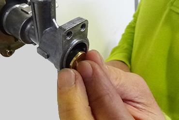
9 2.e Gas Connection See paragraph 2.a Determine the pipe diameter according to current regulations. Before installing the device blow in the gas pipe to eliminate any residue from its manufacturing. Connect the water heater to the internal system s gas pipes and place a tap above the device for the halting and release of gas. The water heaters that are powered by tanks of L.P.G. gas with regulation and interception devices, must be connected correctly so to guarantee the safety of persons and the surrounding area. Follow all related regulations. When initially installing the device qualified persons must perform the following tests: - Check that the internal and external parts of the gas supplying device are sealed; - check that the gas quantity supplied is equal to that required by the device; - check that the device receives the type of gas it is manufactured to process; - check that the gas supply pressure does not go beyond the maximum pressure values displayed on the information plate; - check that the gas supply system supplies the necessary amount of gas to the device and that it is equipped with all the necessary safety devices prescribed by current regulations. If the user is absent for a lengthy period, turn off the main gas supply tap. Do not obstruct the area s ventilation openings where the device is installed to avoid dangers such as the build up of toxic and explosive substances. Do not utilize gas tubes to earth electrical devices. 2.f Water connection Connect the water heater to the water supply and insert a tap to intercept the water above the device. From the front, the cold water input is on the right and the hot water output is on the left. Insert the filter into the water valve input fitting. Remove the plastic nut from the hot water output fittin before connecting it to the water supply. Ensure that the tubes of you water system are not used to earth your electrical system or telephone, they are absolutely inappropriate for performing this task. In a short amount of time this can damage tubes and the device. 2.g Disposal of waste product This B11BS water heater is supplied with a device for releasing flue gas. For output of combustion by-products refer to the regulations in force including any updates. See paragraph 2.a The gas devices with an attachment for a waste gas flue must be connected directly to properly working chimney or flue pipe; only if these devices are not present is it then permitted to release gases directly outside. The fitting of devices to a chimney or flue pipe must occur via a smoke channel. Smoke channels must be connected to a chimney or a smoke channel in the same or adjacent area to where the device is installed and must be made of materials resistant to mechanical strain, heat and the effects of combustion by-products and their condensation. The flue gas temperature must always be above condensation temperature in all points of the smoke channel regardless of external conditions. FLUE GAS RELEASE SAFETY DEVICE The product is equipped with a series of flue gas release safety devices. The device ensures the correct release of combustion byproducts; the flow of combustible gas to the release conduit and the smoke channel. The safety device contains a thermostat, it can stop the flow of gas to the main burner and the pilot flame. The safety device can be triggered by the partial or total obstruction of the release conduit or the smoke channel. To reset the device it is necessary to press the flue gas thermostat key (Fig. 7) close use a screwdriver and reopening the hot water tap. If the device or its electrical connections breaks down, the product can not be put ON, it ensures a safe condition If the device or its electrical connections breaks down, the machine operation is blocked. If the machine is A constantly blocked as a result of the flue gas safety device, it is necessa- Fig Release hood 11 Pressure intake 2 Flue gas safety device 12 Temperature selector Water limit thermostat 4 Heat exchanger 5 Burner 13 Venturi 14 Hydraulic valve 15 Water filter 6 Sensor electrode 16 Membrane Pilot burner 8 Ignition electrode 17 Cold water input 18 Economiser Injector 10 Hot water output 19 Gas valve 20 Safety device Gas Gas filter 22 Battery 23 Electrical card 24 Microswitch Fig. 6 H 2 O 23 H 2 O 9


 - Remove the screws that hold the diffuser in place (Fig. 12) - Turn on the left the pilot group (Fig. 13) - Remove the 4 screws of the gas valve (Fig.")
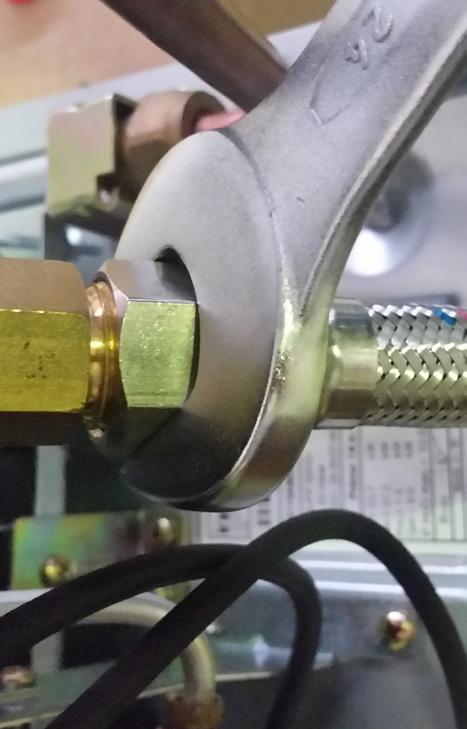
 and turn on the right the water valve and the diffuser as indicated in Fig. 18 - Disconnect the water valve and the diffuser from the water inlet pipe by the nut (see part. 2 in Fig.")
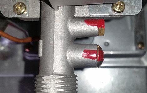
 - Unscrew the injectors and substitute them with those found in the transformation kit (Fig.")
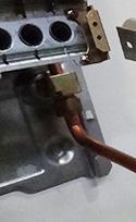
10 ry to request the assistance of a qualified technician according to law in force, to check the correct release of flue gas through the release conduit and/or the smoke channel, according to the installation regulation. It is highly prohibited to attempt to modify or remove the flue gas safety device; this risks the safety of the user and persons in the area. Only a qualified technician who is authorised by the manufacturer can meddle with the safety device in order to check it s functionality or to substitute it if necessary. If it is necessary to replace the device it is vital to only use original parts supplied by the manufacturer since it has been designed, studied and regulated to be fitted with the water heater. 2.h Gas transformation Transforming the product so it may receive a different type of gas can be easily performed even while it is mounted. The instructions for transforming and regulating the product to receive various types of gas are below. This operation must be performed by qualified personnel according to law in force. TRANSFORMATION FROM METHANE TO LPG Transforming the product so it may receive a different type of gas can be easily performed even while it is mounted. Before any operation ensure that the gas and water supply are switched off. I SUBSTITUTION OF THE PILOT INJECTOR - Disconnect the pilot flame tube (Fig. 8-9) - Remove the pilot injector - Insert the seal contained in the transformation kit (Fig. 10) II SUBSTITUTION OF THE BURNER INJECTORS - Remove the screws that hold the pilot flame in position (Fig. 11) - Remove the screws that hold the diffuser in place (Fig. 12) - Turn on the left the pilot group (Fig. 13) - Remove the 4 screws of the gas valve (Fig. 14) - Disconnect the water valve from the water supply removing the inlet connection (Fig. 15) - Disconnect the microswitch s cables (Fig. 16) - Remove the connection (see part. 1 - Fig. 17) and turn on the right the water valve and the diffuser as indicated in Fig Disconnect the water valve and the diffuser from the water inlet pipe by the nut (see part. 2 in Fig. 19 and 17) and at the same time extract the large spring and the small spring/modulation valve set (Fig. 20) - Unscrew the injectors and substitute them with those found in the transformation kit (Fig. 21) III SUBSTITUTION OF THE MODULATION VALVE After the operations of the points I and II - Substitute the modulation valve with the one in the kit - Insert the valve and the large spring, taking care with the direction of the insertion (Fig a) and making sure that the drilled spring guide disc is in its correct position (Fig. 23) IV DISABLING THE GAS ADJUSTER - Remove the protective cap (Fig. 24) - Regulate the supply calibration screws so that the maximum amount of gas can pass (disk completely horizontal), referred to technica data tab. It is necessary to use a pressure regulator that operates at 30 mbar for Butane Gas and at 37 mbar for Propane Gas. The above values must be measured using a barometer connected to the devices pressure entrance. TRANSFORMATION FROM LPG TO METHANE GAS Execute operations I, II and III described above IV ENABLING THE GAS ADJUSTER - Remove the protective cap - Regulate the pressure screws so that the burner reaches the pressure levels indicated on the technical data Ensure that the gas pressure is at 20 mbar. After the gas transformation: Check that all the disassembled parts are perfectly sealed once the device is operational using a soapy solution. Write on adhesive paper Converted to, including the date of the operation, the name and signature of the person who performed the transformation and attach it to the device near the older information plate. WARNING IMPORTANT Fig. 8 Fig. 9 Fig. 10 Fig. 11 Fig. 12 Fig


11 Fig. 14 Fig. 15 Fig Fig. 17 Fig. 18 Fig. 19 Fig. 20 Fig. 21 Fig. 22 Fig. 23 Fig
12 3. OPERATION A = Gas economizer on/off A off position minimum gas level B maximum gas level B = Water temperature selector Fig a Function The water heater is used for the production of instant hot water. The removal of hot water can be preformed by multiple taps. By turning on the relative tap, the main burner switches on heating the water that passes. These devices with a modifiable flame are particularly suited for usage with mechanical mixers and thermostats. This water heater, in contrast with other water heaters with a fixed flame, has a modulation valve to optimise the water heaters operation. It allows for the water to be heated using less water pressure and gas by modulating the flame according to the amount of water used, maintaining the water extracted at a constant temperature. The water heater uses automatic variation that is PROPORTIO- NAL, able to change the gas consumption (modulating the flame) to respond to the amount of water extracted. This device is equipped with an electronic tool that is powered by a 1.5 V battery that automatically switches on the pilot flame and then the burner every time that hot water is extracted. The flame is switched on using a card that ionizes the flame Lipari Tn 11i: for the extraction of 2,5 to 5 l/min the temperature of the water supplied remains at 60 C, (in this case the has valve supplies the burner with the necessary quantity of gas proportional to the water supplied), above 5 l/min to 11 l/min the water temperature varies from 60 C to 40 C. Lipari Tn 14i: for the extraction of 2,5 to 7 l/min the temperature of the water supplied remains at 60 C, (in this case the has valve supplies the burner with the necessary quantity of gas proportional to the water supplied), above 7 l/min to 14 l/min the water temperature varies from 60 C to 40 C If the main burner accidentally switches off, the device will attempt to turn it on again. If within 60 seconds the device does not function it is blocked. The device is built to function with normal water pressure; in addition a temperature selector B is also supplied. Rotate the knob completely to the left to obtain the maximum water output or completely to the right for the minimum water output. The machine is switched off by rotating knob A to the ( OFF) position. When the water heater is not used for long periods close the gas supply tap or the LPG gas valve on the tank. For the best operational results it is recommended to have a qualified technician service the machine at least once a year. Gas economizer The device is equipped with a gas economizing device which is used to choose the temperature of the water so it may be supplied at the temperature necessary while saving gas. The economizing device is activated by turning the knob A until it reaches the picture of the small flame (MIN ). Using the economizer limits the amount of heating when the hot water usage is modest (water supplied is already warm or there is a reduced usage, for example in summer). DANGER OF FREEZING If there is a possibility that the area where the device is stalled could reach below 0 C, the device must be emptied of all water contained. 3.b Usage Ensure that the gas tap and all water taps are switched off - Turn on the Main gas supply tap or that of the gas tank if using Liquefied Petroleum Gas (L.P.G.) - Open the gas tap, not supplied with the device, placed immediately before the water heater on the gas input pipe - Rotate knob A towards the large flame (ON ), during rotation, when the small flame is reached it is necessary to press lightly while turning until it reaches its destination. - When hot water is requested, the device automatically turns on the pilot flame, this lights the main burner. - When the hot water request has terminated (turning the water tap off) the burner automatically switches off, the device then awaits another heating request. If after 60 seconds it does not switch on, the flame detector interrupts the flow of gas and blocks the device. To reuse the device after it has been blocked, close the hot water extraction tap and then reopen it to restart the sequence. 12
13 4. MAINTENANCE To maintain the machine at maximum efficiency, have qualified personnel perform a maintenance check at least once a year. Before cleaning or performing maintenance, opening or disassembling the panels, switch off the device and turn off the gas supply. Check the main burner and the pilot flame, the ignition electrode, the safety valve and that there is no leakage. Check that there is nothing obstructing the passages within the exchanger smoke channel. To clean the outside of the panels utilize a cloth with soap and water. Do not use solvents, powders or abrasive sponges. Do not clean the device and/or its parts with flammable materials (e.g. petrol, alcohol, diesel etc.). 4.a Removing the casing To remove the outer casing follow the steps below: - Remove the selector Knobs (A and B) - Remove the screws (C) - Shift the casing upwards to free it from the upper and lateral hooks - Shift the casing forwards - To reinsert the casing, follow the above steps in reverse order Fig. 26 A B C 13
14 4.b Troubleshooting: problems and solutions For the best functioning of the water heater, to prolong its lifetime and ensure that it is always safe, ensure that it is inspected at least once a year by a trained professional. The trained professional is to perform the following maintenance operations: - Remove any rust from the burner - Remove any deposit on the glow plug by the electrode - Clean the combustion tank - Check the ignition, switching off and general functionality of the device - Check that the gas and water tubes and connections are sealed Warning: the flowing repair instructions are only to be performed by qualified and authorized technicians. PROBLEM CAUSE SOLUTIONS There is no spark - Exhausted battery - Substitute The pilot does not switch on when there is a spark The burner does not switch off when the water turns off The exchanger blade becomes dirty in a small amount of time - Electrical cable of device is disconnected - Insert - Electrical card is broken - Test, substitute - There isn t sufficient water pressure - Repair the device to guarantee pressure, rotate the selector knob all the way to the right - The membrane is broken - Substitute - The electrode is damaged - Substitute - Safety device broken - Substitute - No gas supply - Open the gas tap - Air in the gas tubes - Release gas - Grime on the gas shutter - Test, clean - Valve piston or stem is locked in open position - Micro lever is locked in open position - Test - Disassemble, clean and eventually substitute - If an LPG supply, check the gas pressure - Regulate and if necessary substitute the tank pressure regulator - Poor draught or dusty surroundings - Check the smoke channel efficiency - Yellow flame - Check the gas type and clean the burner - Excess gas consumption - Check and regulate There is a smell of gas - Due to the loss of gas in the tubes, check the tubes and find the leak There is a smell of gas - It can be caused by obstruction in the flue gas circuit - Do not activate electric switches or any object that produces sparks in local area - Check the efficiency of the smoke channel and the flue gas conduit - Excess gas consumption - Check and regulate 14
15 5. GENERAL TERMS OF WARRANTY The Warranty is the one provided by the regulations and laws governing the sale of consumer goods in the country of purchase. For further information contact the dealer/importer. Warranty exclusions The warranty is excluded with respect to damage, malfunctions and defects that may be detected on Fondital gas water heaters and caused by: a) Transport by third parties. b) Negligence in the storage and handling of the product. c) Inability to use the product and accessories, and failure to follow instructions and warnings outlined in the use and maintenance manual supplied. d) Insufficient flow rate and defective gas, water and power supplies. e) Tampering or work by personnel not authorised by the manufacturer. f) Installation of the product in an unsuitable place (internal or external) and problems arising from incorrect or improper installation. g) Inadequacy of flues and/or the flue gas venting pipe and combustion air intake, as well as use of components, flue pipes or heat transfer fluids that are not suitable for the type of products that are installed or are not Fondital original parts. h) Storage in unprotected areas of construction sites. i) Failure to empty the system or premature installation. j) Corrosion of the system and formation of limescale build-up or other deposits arising from the supply water. k) Failure to clean the system with suitable products whether it be new or old. l) Force majeure due to particular weather events (e.g., earthquakes, floods, lightning, storms, excessive precipitation, etc.), as well as fires, vandalism, theft; stray currents and/or harmful effects due to atmospheric elements. m) Use of inadequate fuel and/or in any case for reasons not depending on the manufacturer. n) Forced or prolonged suspension of product operation. Furthermore, the warranty is considered void in the following cases: a) If the end user is not current with payments. b) If the system is not installed in full compliance with regulations and laws, as well as the instructions and warnings published in the installation, use and maintenance manual supplied with the product. c) In case of skipped or inadequate periodic maintenance. d) In case of use of non-original spare parts. Furthermore, these operations are not covered by the warranty: plumbing, electrical, gas supply and flue connections, combustion analysis, as well as activities and operations to access the product, like disassembling furnishings or covers, preparation of scaffolding, use of platforms, cranes etc. Moreover, the customer will bear all the expenses if service is required to rectify erroneous technical work, tampering, or, in any case, damage to the product not attributable to manufacturing defects. 15
16 Fondital S.p.A VOBARNO (Brescia) Italy - Via Cerreto, 40 Tel / Fax / info@fondital.it The manufacturer reserves the right to modify his/her products as deemed necessary, without altering the basic characteristics of the products themselves. Uff. Pubblicità Fondital IST 03 C Aprile 2017 (04/2017) 16
Primo 6 Primo 11. Instantaneous gas water heater. Installation, operation and maintenance manual WATER HEATERS BOILERS RADIATORS
 Primo 6 Primo 11 Instantaneous gas water heater WATER HEATERS BOILERS RADIATORS Installation, operation and maintenance manual The device is well built in accordance with the current legislation. The CE
GAS WATER HEATER INSTALLATION, USE AND MAINTENANCE
 LIPARI TF 11i - 14i IST 03 C 1084-01 GAS WATER HEATER INSTALLATION, USE AND MAINTENANCE EN Translation of the original instructions (in Italian) QUICK-START GUIDE POWER ON Press the power on button. WATER
Gas Instantaneous Water Heater
 6 720 607 823 GB (06.06) SM Installation and Operating Instructions Gas Instantaneous Water Heater WR10..B... WR11..B... With electronic ignition and triple safety system consisting of ionisation detector,
User and maintenance manual
 GB User and maintenance manual IMPORTANT SAFETY INSTRUCTIONS These instructions shall also be available on website: docs.whirlpool.eu. YOUR SAFETY AND THAT OF OTHERS IS HIGHLY IMPORTANT. This manual and
GB User and maintenance manual
 GB User and maintenance manual IMPORTANT SAFETY INSTRUCTIONS These instructions shall also be available on website: docs.whirlpool.eu. YOUR SAFETY AND THAT OF OTHERS IS VERY IMPORTANT This manual and
Instructions for use
 Instructions for use These instructions are also available on the website: www.kitchenaid.eu Important instructions for safety 4 Installation 6 Safeguarding the environment 6 Troubleshooting guide 7 After-sales
HG 675 CX 60 HG 675 CN 60 HG 675 CW 60
 HG 675 X 60 HG 675 CX 60 HG 675 CN 60 HG 675 CW 60 1 2 1. : 93/68: 90/396: 2006/95/CE: 2004/108/CE: - 1935/2004:. 2002/95/CE: RoHS 2.,.,,,,...,. (,..)..,,.,. ( ),,, ;,,.,.....,.,,,,,,...,. (..),,.,..,.,,,,
3gb53231b.fm5 Page 12 Friday, April 11, :21 PM
 3gb53231b.fm5 Page 12 Friday, April 11, 2003 12:21 PM INSTRUCTIONS FOR USE BEFORE USING THE COOKTOP SUGGESTIONS FOR ENVIRONMENT PROTECTION PRECAUTIONS AND GENERAL ADVICE ENERGY SAVING TIPS CARE AND MAINTENANCE
WHE 2.24 / WHE 2.24 FF
 EN Wall-hung gas boilers WHE 2.24 WHE 2.24 FF User Guide 300011777-001-C . Contents 1 Introduction.............................................................................3 1.1 Symbols used...........................................................................................3
Merloni Elettrodomestici. Technical Fitting Manual OVENS. Language Issue/Edition Page GB /
 GB 99-11-03/01 1-18 Index 1 WORKING AND FITTED DIMENSIONS 3 1.1 Oven size 60 cm 3 1.2 Maxioven 4 2 INSTALLING THE FITTED OVEN 5 3 FITTED GAS - INSTALLATION REQUIREMENTS 5 4 FIXING THE OVEN TO THE UNIT
Proline GAS HOB Model TCG40IX Instruction Book
 Proline GAS HOB Model TCG40IX Instruction Book GB Operating and Installation Instructions Index Technical data and specifications...... 3 Installation...................... 3-6 Ventilation........................
Conversion Instructions Logano G234X. Gas boiler. Please read carefully before installing and servicing. Gas boiler
 Gas boiler UPON COMPLETION OF THE INSTALLATION THE INSTALLER MUST INSTRUCT THE OWNER AND OPERATOR ON THE FUNCTIONALITY AND THE PROPER OPERATION OF THE BOILER AND THE HEATING SYSTEM. INSTALLER MUST REVIEW
SAFETY INSTRUCTIONS IMPORTANT TO BE READ
 SAFETY INSTRUCTIONS EN IMPORTANT TO BE READ AND OBSERVED Before using the appliance read these safety instructions. Keep them nearby for future reference. These instructions are valid if the country symbol
IDE 20 / IDE 30 / IDE 50 IDE 60 / IDE 80
 IDE 20 / IDE 30 / IDE 50 IDE 60 / IDE 80 EN OPERATING MANUAL OIL HEATER TRT-BA-IDE20-30-50-60-80-TC-001-EN Table of contents Information on the use of this manual... 1 Scope of delivery... 1 General safety...
Light oil / kerosene burner
 Installation, use and maintenance instructions Light oil / kerosene burner One stage operation CODE MODEL TYPE 374445 G5 444T50 290238 (5) - 05/20 TECHNICAL DATA Thermal power output 28 60 kw 2.3 5 kg/h
INSTALLATION AND MANINTENANCE INSTRUCTIONS
 INSTALLATION AND MANINTENANCE INSTRUCTIONS Appr. Nr. A 9503 T - 0085 AQ 0765 PEGASUS F2 T HIGH EFFICIENCY GAS-FIRED CAST-IRON BOILERS Models 51-68 - 85-102 2 Contents 1. General technical data 2. Dimensional
DH-Direct Fired Poultry Farm Diesel Heater
 DH-Direct Fired Poultry Farm Diesel Heater Comparison of Diesel Heater to Gas Heater Diesel LPG Gas LPG Gas KW 43 70 120 Fuel consumption/hr 3 5.1 8.8 Heat output 37000 60000 100000 Cost of fuel/lit or
Read this manual through carefully before installing/using the cleaner, paying special attention to the SAFETY INSTRUCTIONS
 PW1370TD 2 EN Read this manual through carefully before installing/using the cleaner, paying special attention to the SAFETY INSTRUCTIONS 3 E3 E1 C3 A1-A2-A3-A4 B4 B1 B5 B2 C1 B3 D 1 4 1 2 3 4 5 6 7 Ø13
IMPORTANT SAFETY INSTRUCTIONS DANGER: WARNING:
 IMPORTANT SAFETY INSTRUCTIONS YOUR SAFETY AND THAT OF OTHERS IS PARAMOUNT This manual and the appliance itself provide important safety warnings, to be read and observed at all times. This is the attention
OSC... INSTRUCTION MANUAL - KITCHEN EXTRACTOR HOOD
 OSC... INSTRUCTION MANUAL - KITCHEN EXTRACTOR HOOD EN min 450mm Electrical cookers min 650mm Gas cookers min 650mm Gas cookers 1a 1b 1c 2a 2b ELECTRICAL / GAS - 650mm 3a 3b 2 2 x 8 3c 3d 3e 3 0 1 2 3 L
User s Information Manual
 User s Information Manual Model NPE-24AWE NPE-24SWE NPE-32AWE NPE-32SWE Condensing Water Heater These appliances are for use with natural gas or LPG. (An LPG conversion kit is included with the water heater.)
INSTALLATION AND MAINTENANCE MANUAL. Alcor FA
 INSTALLATION AND MAINTENANCE MANUAL IST 03 F 048-01 Alcor FA Aluminium electric radiators with heat transfer fluid EN Dear customer, Thank you for choosing our product. Read this manual carefully before
USER MANUAL. 80 cm 2 burners, glass hob AKC 820C/BLM
 USER MANUAL 80 cm 2 burners, glass hob AKC 820C/BLM For your safety These instructions have been drawn up for your safety and that of others. You are therefore requested to read them carefully before installing
Table Top Patio Heater
 Table Top Patio Heater INSTRUCTION MANUAL MODEL: HPS-B Certified by international recognized standards. The infra-red with heat wave outdoor heater. Variable control gas valve with electric push igniter.
Instructions for use
 Instructions for use These instruction shall be available on website docs.kitchenaid.eu Important instructions for safety 4 Installation 6 Safeguarding the environment 6 Troubleshooting guide 7 After-Sales
IN 900 BIC UK INSTRUCTION MANUAL - KITCHEN EXTRACTOR HOOD
 IN 900 BIC UK INSTRUCTION MANUAL - KITCHEN EXTRACTOR HOOD EN Before using the appliance, please carefully read this manual! 2 3 min 450mm Electrical cookers min 650mm Gas cookers min 650mm Gas cookers
Fully-automatic Gas tankless Water Heater USER'S MANUAL FOR MODEL EZ-101 ISO9001 certified
 Fully-automatic Gas tankless Water Heater USER'S MANUAL FOR MODEL EZ-101 ISO9001 certified Thank you for purchasing our fully-automatic gas-fired tankless water heater. Please completely read this Manual
INSTALLATION AND MAINTENANCE MANUAL BLITZ FD_
 INSTALLATION AND MAINTENANCE MANUAL IST 03 F 017-01 BLITZ FD_ Aluminium electric radiators with heat transfer fluid GB Dear customer, Thank you for choosing our product. Read this manual carefully before
PC 640 GB. Built-in cooking tables 60 Instructions for installation and use
 PC 640 GB Built-in cooking tables 60 Instructions for installation and use Congratualtions on choosing an Ariston appliance, which you will find is dependable and easy to use. We recommend that you read
Instruction manual for downdraft hood
 Instruction manual for downdraft hood Model code: BODY / DD600BK - BODY / DD900BK BODY / DD600SS - BODY / DD900SS Contact Caple on 0844 800 3830 or for spare parts www.4caple.co.uk The symbol on the product
Installation and Operating Instructions
 Installation and Operating Instructions Models: Verso 4G Hob As part of Parmco Appliances commitment to improving and updating product ranges, we reserve the right to alter, change and update technical
Divacondens D Plus Atmospheric condensation wall-mounted boilers, with instant domestic hot water production
 Divacondens D Plus Atmospheric condensation wall-mounted boilers, with instant domestic hot water production THE SIMPLEST SOLUTION FOR A CONDENSING BOILER DIVACONDENS D PLUS is the generator of condensation
Light oil burners. One stage operation
 Installation, use and maintenance instructions Light oil burners One stage operation CODE MODEL TYPE 3505 RDB CF 38 50 T3 350050 RDBR CF 6 50 TR 35050 RDBR CF 33 50 TR 35050 RDBR CF 38 50 T3R 350650 RDBR
User Manual FLOWMAX-90. for model. Condensing water heater 85,000 BTU. Installation, operating, commissioning and maintenance instructions.
 User Manual for model FLOWMAX-90 Condensing water heater 85,000 BTU WARNING If the information in these instructions is not followed exactly, a fire or explosion may result, causing property damage, personal
User Manual RBS 24. for model CE series ENERGY. Wall mounted instantaneous combi boiler room sealed chamber
 User Manual for model RBS 24 series ENERGY Wall mounted instantaneous combi boiler room sealed chamber CE 0694 RBS 24 - SERIE ENERGY - RAD - ING - MAN.UT - 1407.1 - DIGITECH TR - MIAH6 - E04 Technical
EN Instruction on mounting and use
 EN Instruction on mounting and use EN - Instruction on mounting and use Closely follow the instructions set out in this manual. All responsibility, for any eventual inconveniences, damages or fires
USERS MANUAL FOR GAS BOILERS
 USERS MANUAL FOR GAS BOILERS PLEASE READ THE MANUAL CAREFULLY: IT CONTAINS IMPORTANT INFORMATION REGARDING SAFETY, INSTALLATION, USE AND MAINTENANCE OF THE APPLIANCE MODELS: NOVADENS 24 NOVADENS 24C NOVADENS
VICTRIX 90 VICTRIX 115 Wall-hung condensing boilers for high power
 VICTRIX 90 VICTRIX 115 Wall-hung condensing boilers for high power VICTRIX 90 is the new wall-hung condensing boiler for room heating only, set-up for independent functioning and for that in cascade mode
IST 03 C ELBA DUAL INSTALLATION, USE AND MAINTENANCE
 IST 03 C 202-01 ELBA DUAL INSTALLATION, USE AND MAINTENANCE GB Thank you for choosing our boilers. Please read these installation and maintenance instructions with care. Please note that the boiler must
Operating instructions
 6304 0307 04/2005 US For the installer Operating instructions Sealed combustion boiler Logano GA24 SC and atmospheric boiler Logano G24X II/SP If these instructions are not followed exactly, a fire or
ZEST HOOD. Instructions Manual.
 ZEST HOOD Instructions Manual www.rangemaster.co.uk INDEX EN RECOMMENDATIONS AND SUGGESTIONS... 3 CHARACTERISTICS... 4 INSTALLATION... 6 USE... 14 MAINTENANCE... 16 2 RECOMMENDATIONS AND SUGGESTIONS The
The guarantee on this appliance is valid for 12 months from the first day of installation.
 Users Manual Dear Customer, Thank you for choosing an ARISTON boiler. We guarantee that your boiler is a reliable and technically sound product. This Users Manual provides detailed instructions and recommendations
E-COMBI EVO E-SYSTEM EVO
 E-COMBI EVO E-SYSTEM EVO User s manual CONDENSING WALL-HUNG GAS BOILER G.C.N.:47-116-68 (24 kw) G.C.N.:47-116-69 (30 kw) G.C.N.:47-116-70 (38 kw) G.C.N.:41-116-39 (24 kw) G.C.N.:41-116-40 (30 kw) Country
TAHITI CONDENSING KR 55 - KR 85
 IST 03 C 351-01 TAHITI CONDENSING KR 55 - KR 85 GB INSTALLATION USE AND MAINTENANCE Dear Customer, Thank you for choosing and buying one of our boilers. Please read these instructions carefully. They will
Operating instructions
 6 720 804 891 2012/10 EN-US For the installer Operating instructions Sealed combustion boiler Logano GA124 SC If these instructions are not followed exactly, a fire or explosion may be caused with serious
Condensing, pre-mixed, wall-hung gas boilers with water tank
 C 271-01 made in Italy Nias condensing Condensing, pre-mixed, wall-hung gas boilers with water tank Life-enhancing heat GB Condensing, pre-mixed, wall-hung boilers with water tank Nias CONDENSING HIGH
Porter & Charles OPERATION MANUAL. Gas Cooktop CG60S, CG76S, CG90S, CG60W, CG90W
 Porter & Charles OPERATION MANUAL Gas Cooktop CG60S, CG76S, CG90S, CG60W, CG90W Congratulations on the purchase of your Porter & Charles appliance. We are sure it will provide many years of great cooking
USER MANUAL. 60cm, 3 burners, Hob AKC 630
 USER MANUAL 60cm, 3 burners, Hob AKC 630 For your safety These instructions have been drawn up for your safety and that of others. You are therefore requested to read them carefully before installing
Installation and Operating Instructions. Models: T4-12LOW-9IS
 Installation and Operating Instructions Models: T4-12LOW-9IS Dear Valued Customer, Thank you and congratulations on purchasing your new Parmco appliance. All Parmco products are made to the highest quality
Cooker Hood Instruction Manual
 Cooker Hood Instruction Manual Model number(s): RHSCH601SS/B & RHSCH901SS/B IMPORTANT: RETAIN FOR FUTURE REFERENCE Contents Safety Instructions. 3-6 Product Overview. 7 Positioning. 8 Operational modes.
1 VICTRIX ZEUS Superior kw I features
 Wall-hung condensing VICTRIX ZEUS Superior kw I is the new range of wall-hung condensing boilers with 54 litre stainless steel storage tank available in two versions with nominal heat output of 26 kw and
Operating instructions
 The energy you need Operating instructions Betacom 3 24c -A (H-GB) 30c -A (H-GB) GB, IE Contents Contents 1 Safety... 3 1.1 Action-related warnings... 3 1.2 Intended use... 3 1.3 General safety information...
Gas Fire Patio Heater Q9
 Gas Fire Patio Heater Q9 Instruction Manual Please read the manual BEFORE you unpack or install the fire TABLE OF CONTENTS Warning 3 Getting Started 4 What s Included 5 Assembly Procedures 6 Product Drawing
Cooker Hood LA-72-CAN.
 Cooker Hood LA-72-CAN EN www.luxairhoods.com WARNINGS Safety This equipment can be used by children aged 8 or more, people with physical, mental and sensory disabilities or inexperienced users it they
INSTALLATION AND USER S MANUAL COOKER HOOD RS-600/A-S
 INSTALLATION AND USER S MANUAL COOKER HOOD RS-600/A-S RS-600 (CHS60SS)-GB-05.indd 1 6/8/2010 9:30:59 AM TABLE OF CONTENTS 1. Introduction 2 2. Safety precaution 2 3. Intended use 3 4. Parts supplied 3
PDG PDG4.1...A PDG5.0...A INSTRUCTION MANUAL IO 00450/2 ( )
") PDG4.0... PDG4.1...A PDG5.0...A INSTRUCTION MANUAL IO 00450/2 (11.2010) DEAR CUSTOMER, Outstanding user-friendliness and excellent efficiency make cooktops a perfect choice. Please read this manual thoroughly
PDG4.0... PDG4.1...A PDG5.0...A INSTRUCTION MANUAL IO 00450/2 (11.2010) DEAR CUSTOMER, Outstanding user-friendliness and excellent efficiency make cooktops a perfect choice. Please read this manual thoroughly
Servicing manual. Wall-mounted condensing gas boiler 600 Series - 11S / 19S / 24S / 24C /2002 GB(EN) For trade use
 For trade use") GB122 7210 1300-12/2002 GB(EN) For trade use Servicing manual Wall-mounted condensing gas boiler 600 Series - 11S / 19S / 24S / 24C Please read thoroughly before attempting to diagnose fault List of contents
GB122 7210 1300-12/2002 GB(EN) For trade use Servicing manual Wall-mounted condensing gas boiler 600 Series - 11S / 19S / 24S / 24C Please read thoroughly before attempting to diagnose fault List of contents
Operating instructions
 Operating instructions Capriz 2 24c 28c GB, IE Contents Contents 1 Safety... 3 1.1 Action-related warnings... 3 1.2 Intended use... 3 1.3 General safety information... 4 2 Notes on the documentation...
Servicing manual. 600 Series - 11S / 19S / 24S / 24C. Wall-mounted condensing gas boiler. For trade use
 GB122 Servicing manual Wall-mounted condensing gas boiler 600 Series - 11S / 19S / 24S / 24C For trade use Please read thoroughly before attemting to diagnose fault 7217 4900 (03/2010) GB/IE List of contents
Operating instructions
 Operating instructions Gas-fired condensing boiler Logano plus GB312 For the user Please read carefully before use 7 747 009 296-01/2007 EN Contents 1 For your safety..............................................
Operating Instructions HOB
 PHN 942 T/IX/A English Operating Instructions HOB Operating Instructions,1 Warnings,2 Assistance,3 Description of the appliance,4 Installation,5 Start-up and use,9 Precautions and tips,9 Maintenance and
60cm Integrated Turbo Extractor
 60cm Integrated Turbo Extractor LAM2201 User & Installation Guide Dear Customer, Congratulations on your choice of domestic appliance which has been designed to give you excellent service. The user manual
W - WR - WD. Technical information W- WR - WD. Gas-fired convection heaters with fan
 Gas-fired convection heaters with fan W - WR - WD Technical information A2B srl - Via d Ancona, 37-60027 Osimo (An) Tel. 071.723991 - Fax 071.7133153 - Web Site: www.accorroni.it - E-mail: a2b@a-2-b.it
ATMOSPHERIC GAS BOILER INSTALLATION, OPERATING AND MAINTENANCE MANUAL
 STREBEL GENEVA CE ATMOSPHERIC GAS BOILER INSTALLATION, OPERATING AND MAINTENANCE MANUAL INDEX TABLE 1 TECHNICAL DATA SECTION 1 SECTION 2 SECTION 3 SECTION 4 SECTION 5 SECTION 6 SECTION 7 SECTION 8 SECTION
VICTRIX Superior kw Export VICTRIX Superior kw X Export
 Wall-hung condensing VICTRIX Superior kw is the instantaneous sealed chamber wallhung boiler with power of 32 kw which, thanks to condensation technology, is characterised for its high efficiency and guarantees
T UNI 7000 F. Operating instructions For the user (2006/05) AU/GB
 AU/GB") 6 720 648 662-00.1T UNI 7000 F Operating instructions For the user AU/G 2 Contents Contents Contents 2 1 Safety information and explanation of symbols 3 1.1 For your safety 3 1.2 Explanation of symbols
6 720 648 662-00.1T UNI 7000 F Operating instructions For the user AU/G 2 Contents Contents Contents 2 1 Safety information and explanation of symbols 3 1.1 For your safety 3 1.2 Explanation of symbols
Mod. ANBR9..G. CR DOC. NO. GAS-HEATED TILTING BRATT PAN. INSTRUCTIONS FOR INSTALLATION, ADJUSTMENT, USE AND MAINTENANCE...
 -HEATED TILTING BRATT PAN Mod. ANBR9..G. INSTRUCTIONS FOR INSTALLATION, ADJUSTMENT, USE AND MAINTENANCE...page 2-5 APPENDIX....pagina 6-7 Read the manual thoroughly and keep it in a safe place throughout
USER GUIDE. DRENA 2 - User Manual ELECTRICAL PANEL FOR 2 MOTORS - WASTE WATER -
 USER GUIDE DRENA 2 - User Manual ELECTRICAL PANEL FOR 2 MOTORS - WASTE WATER - II CONTENTS 1. SYMBOLS AND WARNINGS... 5 2. GENERAL INFORMATION... 6 3. WARNINGS... 7 4. GENERAL DESCRIPTION... 8 5. INSTALLATION...
LIBRA DUAL INSTALLATION USE AND MAINTENANCE. Italian product. High quality IST 04 C
 LIBRA DUAL High quality Italian product GB INSTALLATION USE AND MAINTENANCE IST 04 C 220-02 Dear Customer, Thank you for choosing and buying one of our boilers. Please read these instructions carefully
INSTALLATION AND OPERATING INSTRUCTIONS BIOCLASS HM
 INSTALLATION AND OPERATING INSTRUCTIONS BIOCLASS HM Thank you for choosing a DOMUSA TEKNIK heating boiler. Within the product range offered by DOMUSA TEKNIK you have chosen BioClass HM model. With a suitable
Read installation manual prior to installation of this unit! Read user manual before putting this unit in operation!
 Gas Instantaneous Water Heater WR 11/14/18.G... Installation Manual and Operating Instructions ZA Read installation manual prior to installation of this unit! Read user manual before putting this unit
User Manual. 110 Cup (55 Cup Raw) Gas Rice Cooker. Model: 177GRCLP, 177GRCNAT 12/2018. Please read and keep these instructions. Indoor use only.
 Gas Rice Cooker. Model: 177GRCLP, 177GRCNAT 12/2018. Please read and keep these instructions. Indoor use only.") 110 Cup (55 Cup Raw) Gas Rice Cooker Intertek 5010781 Conforms to ANSI STD Z83.11-2016 Model: 177GRCLP, 177GRCNAT 12/2018 FOR YOUR SAFETY Do not store or use gasoline or other flammable vapors or liquids
110 Cup (55 Cup Raw) Gas Rice Cooker Intertek 5010781 Conforms to ANSI STD Z83.11-2016 Model: 177GRCLP, 177GRCNAT 12/2018 FOR YOUR SAFETY Do not store or use gasoline or other flammable vapors or liquids
User Manual. 600mm, 700mm & 900mm Gas Cooktops Model No. CF6GS, CF6GW, CF7GS, CF9GS
 User Manual 600mm, 700mm & 900mm Gas Cooktops Model No. CF6GS, CF6GW, CF7GS, CF9GS For all product enquires, including warranty support, please contact our Customer Care team 1800 444 357 or email customercare@hapl.com.au
FLAME HEATER PYRAMID CLFH-10SS OPERATION INSTRUCTIONS
 FLAME HEATER PYRAMID CLFH-10SS OPERATION INSTRUCTIONS www.colorato.net For outdoors use only Uses propane, butane or LPG only Reflector: 47x47 mm Total Height: 2250 mm Regulator s external pressure: 28-30
PHCZ6511 / KMG13169C / PHCG4.1ZpZtC
 PHCZ6511 / KMG13169C / PHCG4.1ZpZtC INSTRUCTION MANUAL EN DEAR CUSTOMER, Outstanding user-friendliness and excellent efficiency make cooktops a perfect choice. Please read this manual thoroughly before
Bosch 80% AFUE Gas Furnace BGS80 Model
 Bosch 80% AFUE Gas Furnace BGS80 Model 4-Way Multipoise Category I Fan-Assisted Furnace User's Information Manual 3124627 2 Bosch 80% AFUE Gas Furnace User's Information Manual Data subject to change 06.2018
BUILT-IN GLASS HOB MODEL: EGH-G8592G(BK) EGH-G8593G(BK) Owner s Manual Please read this manual carefully before operating your set.
 EGH-G8593G(BK) Owner s Manual Please read this manual carefully before operating your set.") BUILT-IN GLASS HOB MODEL: EGH-G8592G(BK) EGH-G8593G(BK) Owner s Manual Please read this manual carefully before operating your set. Retain it for future reference. Record model number and serial number
BUILT-IN GLASS HOB MODEL: EGH-G8592G(BK) EGH-G8593G(BK) Owner s Manual Please read this manual carefully before operating your set. Retain it for future reference. Record model number and serial number
Operating instructions
 Operating instructions For the operator Operating instructions HOME SYSTEM GB, IE Publisher/manufacturer Vaillant GmbH Berghauser Str. 40 D-42859 Remscheid Tel. +49 21 91 18 0 Fax +49 21 91 18 28 10 info@vaillant.de
User s Information Manual
 Condensing Combi Boiler User s Information Manual These appliances are for use with natural gas or LPG. (An LPG conversion kit is included with the boiler.) Type: B23-B33-B53-C13-C33-C43-C53-C63-C83 Gas
Instructions for use
 Instructions for use These instructions are also available on the website: www.kitchenaid.eu Important instructions for safety 4 Installation 6 Safeguarding the environment 6 Troubleshooting guide 7 After-sales
Heating, Air Conditioning, Ventilation. Отопление-Кондиционеры-Вентиляция. MTM 8-30 kw UNIVERSAL OIL HEATER OPERATING MANUAL
 Heating, Air Conditioning, Ventilation Отопление-Кондиционеры-Вентиляция MTM 8-30 kw UNIVERSAL OIL HEATER OPERATING MANUAL 1. Usage MTM 8-30 universal oil heater is designed for heating commercial rooms
INDEX RECOMMENDATIONS AND SUGGESTIONS... 4 CHARACTERISTICS... 5 INSTALLATION... 6 USE... 9 MAINTENANCE... 11
 INDEX EN RECOMMENDATIONS AND SUGGESTIONS... 4 CHARACTERISTICS... 5 INSTALLATION... 6 USE... 9 MAINTENANCE... 11 2 RECOMMENDATIONS AND SUGGESTIONS The Instructions for Use apply to several versions of this
HOW TO USE YOUR 2500 RANGE L.P.G. COOKER OR HOB UNIT
 HOW TO USE YOUR 2500 RANGE L.P.G. COOKER OR HOB UNIT CAUTION These instructions must be read and understood before proceeding with the installation and to avoid any possibility of accident it is essential
Operating Instructions HOB Contents
 PAA 642 /I(WH) PAA 642 /I(BK) UK English Operating Instructions HOB Contents Operating Instructions,1 Warnings,2 Assistance,3 Description of the appliance,4 Installation,5 Start-up and use,9 Precautions
Hamlet 60 & 80 Wall Hood
 Hamlet 60 & 80 Wall Hood Installation & User Instructions Please read these instructions carefully before installing and operating this appliance 1 Contents 1. Introduction 3 2. Health and Safety 3-4 3.
HVG620 & HVG720 Gas Hob Manual for Installation, Use and Maintenance
 HVG620 & HVG720 Gas Hob Manual for Installation, Use and Maintenance Customer Care Department The Group Ltd. Harby Road Langar Nottinghamshire NG13 9HY T : 01949 862 012 F : 01949 862 003 E : customer
User Manual for model RK 18 RK 25 RK 34 CE 0694 RK 18_25_34 - RAD - ING - MAN.UT A - DIGITECH 2 - REGNO UNITO - EXTRAHEAT - CBD
 User Manual for model RK 18 RK 25 RK 34 Premix condensing boiler User instruction CE 0694 RK 18_25_34 - RAD - ING - MAN.UT - 1104A - DIGITECH 2 - REGNO UNITO - EXTRAHEAT - CBD Technical specification by
Remeha. Fuel oil/gas boilers P 520. Installation and Service Manual A
 Remeha Fuel oil/gas boilers EN Installation and Service Manual 300016859-001-A 63115 Declaration of conformity The appliance complies with the standard model described in declaration of compliance. It
JUMBO INDIRECT FIRED DIESEL HEATER OPERATING INSTRUCTIONS
 JUMBO INDIRECT FIRED DIESEL HEATER OPERATING INSTRUCTIONS Before using the heater, read and understand all instructions and follow them carefully. The manufacturer is not responsible for damages to goods
VELA COMPACT INSTALLATION USE AND MAINTENANCE
 VELA COMPACT GB INSTALLATION USE AND MAINTENANCE IST 04 C 167-04 Dear Customer, Thank you for choosing and buying one of our boilers. Please read these instructions carefully in order to install, operate,
User Manual for model
 User Manual for model RKA 24 /20 Wall mounted storage combi boiler premix condensing boiler CE 0694 Technical specification RADIANT BRUCIATORI S.p.A. Montelabbate RKA 24.20 - RAD - ING - MAN.UT - 1309.1
VIESMANN. Operating instructions VITODENS 050-W. for the system user. With constant temperature or weather-compensated control unit
 Operating instructions for the system user VIESMANN With constant temperature or weather-compensated control unit VITODENS 050-W 9/2014 Please keep safe. Safety instructions For your safety Please follow
SAFETY AND OPERATING MANUAL
 SAFETY AND OPERATING MANUAL HOT WATER ELECTRIC WATER BLASTERS Read Safety & Operating Instructions Before Commencing Operation THESE INSTRUCTIONS MUST BE READ AND ADHERED TO BEFORE OPERATING THIS MACHINE.
USHO COOKER INSTALLATION INSTRUCTIONS SAFETY INSTRUCTIONS USER INSTRUCTIONS MODEL: USHO. INSTRUCTION REF: IN152 ISSUE No. 4 DATE
 Page 1 of 11 INSTALLATION INSTRUCTIONS SAFETY INSTRUCTIONS USER INSTRUCTIONS USHO COOKER MODEL: USHO Page 2 of 11 WARNING To avoid scratching the highly polished exterior surface of this equipment whilst
51AKS I S O OWNER S MANUAL
 LLOYD'S REGISTER QUALITY ASSURANCE 51AKS I S O 9 00 1 OWNER S MANUAL This manual applies to the following models Stand-alone Split 51AKS 085--- 51AKS 010--- 51AKS 185--- 51AKS 013--- 51AKS 113--- 51AKS
GUH90 90 cm Canopy Hood
 User Manual for your GUH90 90 cm Canopy Hood NOTE: This User Instruction Manual contains important information, including safety & installation points, which will enable you to get the most out of your
Built-in Gas Hob. Important - Please read these instructions fully before using. Operating Instructions -Please keep for future reference
 Built-in Gas Hob Operating Instructions -Please keep for future reference A70GCIS Important - Please read these instructions fully before using These instructions contain important information which will
Operating Instructions HOB Contents
 THP 641 W/IX/I English Operating Instructions HOB Contents Operating Instructions,1 Warnings,2 Assistance,2 Description of the appliance,3 Installation,4 Start-up and use,7 Precautions and tips,7 Maintenance
MICATHERMIC PANEL HEATER
 EN MICATHERMIC PANEL HEATER OPERATING INSTRUCTIONS Read the instructions carefully before operating the panel or carrying out maintenance operations. Observe all the safety instructions; failure to observe
Gas Fire Patio Heater Lhotse-817
 Gas Fire Patio Heater Lhotse-817 Instruction Manual Please read the manual BEFORE you unpack or install the fire TABLE OF CONTENTS Warning 3 Getting Started 4 What s Included 5 Assembly Procedures 6 Product