MINI CHILLER INVERTER H4 Service manual MUENR-H4 (5, 7, 10, 12, 14, 16 kw)
|
|
|
- Domenic Nichols
- 6 years ago
- Views:
Transcription
1 MINI CHILLER INVERTER H4 Service manual MUENR-H4 (5, 7, 10, 12, 14, 16 kw) CL25610 to CL25615 English
2 Content 1. Outdoor units lineup Nomenclature Features Description of main components Specifications Dimensions Piping Diagram Wiring Diagram Electric Characteristics Tables Operation Limits Water Pressure Drop Sound Level Exploded View Installation Checking and Starting Up the Unit Running and Maintenance Controller Troubleshooting Optional Accessories Mundoclima reserves the right to discontinue, or change at any time, specifications or designs without notices and without incurring obligations. 2
3 1. Outdoor units lineup Model Supply (V/Ph/Hz) Compressor type DC Inverter Heat exchanger A/C mode Hydraulic module Refrigerant MUENR-05-H / 1N / 50 5,0 kw Plate type Heat pump Built-in R410A MUENR-07-H / 1N / 50 7,0 kw DC Inverter Plate type Heat pump Built-in R410A Model MUENR-10-H4 Supply (V/Ph/Hz) / 1N / 50 10,0 kw Compressor type DC Inverter Heat exchanger Plate type A/C mode Heat pump Hydraulic module Built-in Refrigerant R410A MUENR-12-H4 MUENR-14-H / 3N / 50 11,2 kw DC Inverter / 3N / kw DC Inverter Plate type Plate type Heat pump Heat pump Built-in Built-in R410A R410A MUENR-16-H / 3N / kw DC Inverter Plate type Heat pump Built-in R410A 3

4 3.Features 3.1 High efficient DC inverter compressor Full DC inverter mini chiller adopts highly intelligent inverter-driven compressor. This advanced technology enables the output of the outdoor unit to be modulated by the real heat load demands.. This advanced system ensures precise temperature regulation and highly efficient energy usage, making a significant contribution to limiting the impact on the environment. Highly Efficient DC Motor: - Creative motor core design - High density neodymium magnet - Concentrated type stator -Wider operating frequency range Better balance and Extremely Low Vibration: - Twin eccentric cams - 2 balance weights Compressor (Twin Rotary) structure Highly Stable Moving Parts: - Optimal material matching rollers and vanes -Optimize compressor drive technology - Highly robust bearings -Compact structure 3.2 High performance heat exchanger The new designed window fins enlarge the heat-exchanging area, which decrease the air resistance, save more power and enhance heat exchange performance. Hydrophilic film fins and inner-threaded copper pipes optimize heat exchange efficiency. New design Original design High efficiency inner-thread pipe, enhance heat transfer. 3.3 Low-operating sound design Optimally design fan shape and new designed discharge air grille and air deflector, making higher air volume and lower operation sound. Air deflector New grille New fan 4

5 3.4 High efficiency EER kW 7kW 10kW 12kW 14kW 16kW COP kW 7kW 10kW 12kW 14kW 16kW 3.5 More Safety Adopts new standard fan guard. The new grille is more compact. It is more safe for children. 3.6 Wide operation temperature range Stable and safe running at wide ambient temperature range, cooling performance from -5 C to 46 C, heating from -15 C to 27 C. -5 C COOLING MODE 46 C HEATING MODE -15 C 27 C C(D.B.) Outdoor temp. 5

 or SW3_1(12-16kW) on the PCB to ON to enable the following remote control")


 Note: When connecting wired controller, outdoor unit control panel is mainly used for display which can")

6 3.7 Energy saving and high reliability By adopting high efficiency plate heat exchanger, the energy consumption can be reduced. a. Metallic protective cabinet with rustproof polyester paint; b. Built-in with voltage protection, current protection, anti-freezing protection, water flow protection and etc., effectively guarantee the system to work safely. 3.8 User friendly remote control Switch SW4_1(10kW) or SW3_1(12-16kW) on the PCB to ON to enable the following remote control functions. The setting is not default at factory. Remote shut down Remote cooling and heating Note: When all controller controls together, the unit will work according to the last order. 5/7kW will be available soon. 3.9 Flexible and convenient control Built-in electronic controller at factory. Compact devices with advanced function and friendly user interface. The chiller can be controlled by wired controller (KJR-120F1/BMK-E) also which is optional chosen. KJR-120F1/BMK-E (CL92340) Note: When connecting wired controller, outdoor unit control panel is mainly used for display which can check parameters and inquiry, and can t be used to set mode and temperature. Built-in water pressure gauge. Inspect the water pressure all the time Integrated and compact design Fully integrated and built-in hydraulic module, such as expansion tank, plate type of heat exchanger, water circulating pump, etc. It saves installation space and cost EXV control flow more precisely Patented liquid distribution components to maximize performance and minimize defrost impact. 6


7 Stable and accurate gas flow control. EXV achieves 500 pulses to adjust flow precisely. Ensure the temperature-control precisely and steadily to provide a comfortable environment. Fast respond resulting in higher efficiency and improved reliability. 100% 95% 90% 85% 80% 75% 70% 65% 60% 55% 50% 45% 40% 35% 30% 25% 20% 15% 10% 3.12 Water pump starts/stops compulsory function Press Check button for 3 seconds to start the water pump operating when the unit is standby. Press Check button for 3 seconds again to stop the water pump. 7

8 4. Description of main components Structure Panels and base are made from galvanized steel plate painted with epoxy power to ensure total resistance to atmospheric pollution, condensate collection pan as standard. Condenser coils: The coils are made from high performance and seamless copper tuber and high surface area aluminum fins to ensure optimum heat exchange capability. Condenser coil protection grill is standard. Fan motor: To achieve high efficiency heat exchange, the unit is equipment with the high performance axial-flow fans. The fan is driven directly by weather proof motor to ensure reliable operation, the fan motor is six-pole electric motor with built-in thermal cut-out. Evaporator: The heat exchanger is made of AISI 316 stainless steel to ensure high heat exchange efficiency, complete with electric heater and differential pressure switch. The complete heat exchanger is insulated with thermal insulation closed cell rubber foam to give optimum thermal insulation. Hydraulic module: It is fully integrated and equipped with key hydraulic components such as expansion tank, plate type of heat-exchanger, water circulating pump. The water pressure difference switch is provided in the units to protect against damage to the water pump. and control electrical panel and control electrical panel constructed in accordance with IEC 204-1/EN , complete with compressor contactor, control via control panel Electrical panel 2 Display panel 3 Plate heat exchanger 4 4-way valve 5 High pressure switch 6 Low pressure switch 7 Water Pump 8 Accumulator 9 Water flow switch 10 Compressor 11 Condenser 12 Expansion tank 13 Axial-flow fan 5/7KW 8
9 ~16KW 1 Operation panel 2 Water manometer 3 Automatic discharge valve 4 Axial-flow fan 5 Differential pressure switch 6 Condenser 7 Accumulater 8 Security discharge 9 Electric expansive valve 10 Plate heat exchanger 11 Electrical panel 12 High pressure switch 13 4-ways valve 14 Expansion tank 15 Pump 16 Low pressure switch 17 Storage tank 18 Compressor 19 Water supply valve 9
10 5. Specifications Model supply V-Ph-Hz MUENR-05-H , 1, 50 MUENR-07-H , 1, 50 Cooling*(1) kw Input kw Cooling*(2) kw Input kw Heating*(3) kw Input kw Heating*(4) kw Input kw EER*(1) kw/kw EER*(2) kw/kw Max. input consumption kw Max. input current A Model SNB172FJGMC SNB172FJGMC Type ROTARY ROTARY Brand Mitsubishi Electric Mitsubishi Electric kw Compressor Input kw Rated load current A Locked rotor Amp A Thermal protector Inner Inner Refrigerant oil ml FV50S,400 FV50S,400 Model WZDK170-38G-1 WZDK170-38G-1 Type DC Motor DC Motor Outdoor fan motor Brand NIDEC SHIBAURA NIDEC SHIBAURA Input W Speed r/min Number of rows 2 2 Tube pitch(a) row pitch(b) mm Fin spacing mm Fin type Hydrophilic aluminum foil Hydrophilic aluminum foil Outdoor coil Tube outside dia. and type mm φ7.94 φ7.94 Inner grooved copper tube Inner grooved copper tube Coil length height mm Number of circuits 6 6 Type RS15/6-3-WILO RS15/6-3-WILO Water pump Input (H/M/L) W 93/67/46 93/67/46 Pumping head m Outdoor air flow m 3 /h Throttle EXV+capillary EXV+capillary Outdoor noise level (sound pressure)*(3) db(a) Water flow m 3 /h The plate heat-exchanger water pressure drop kpa The Max. and Min. water inlet pressure kpa 500/ /150 Net dimension (W H D) mm Outdoor unit Packing dimension (W H D) mm Net/ Gross weight kg 81/91 81/91 Refrigerant Type R410A R410A Charged volume kg Connection wiring wire mm Signal wire mm Pipe diameter Water inlet/outlet inch 1 1 Control Wired controller Wired controller Ambient temperature Cooling: -5 ~46 ; Heating: (Antifreeze must be added below 5 ) Water outlet temperature range Cooling: 4~20 ; Heating: 30~55 Note: Specifications are based on the following conditions: 1. Cooling: (*1) chilled water inlet/outlet temperature: 12/7 C,outdoor ambient temperature 35 C DB. (*2) chilled water inlet/outlet temperature: 23/18 C,outdoor ambient temperature 35 C DB. 10
11 2. Heating: (*3) warm water inlet/outlet temperature: 40/45 C,outdoor ambient temperature 7 C DB/6 C WB. (*4) warm water inlet/outlet temperature: 30/35 C,outdoor ambient temperature 7 C DB/6 C WB. 3. It is tested 1m away in front of the unit in a semi-anechoic room(sound pressure). 4. The above data may be changed without notice for future improvement on quality and performance. Model MUENR-10-H4 MUENR-12-H4 supply V-Ph-Hz , 1, , 3, 50 Cooling*(1) kw 10.0(2.9~10.5) 11.2(3.1~12.0) Input kw Cooling*(2) kw Input kw Heating*(3) kw 11.0(3.2~12.0) 12.3(3.3~13.2) Input kw Heating*(4) kw Input kw EER(*1) kw/kw EER(*2) kw/kw Max. input consumption kw Max. input current A Model ATQ420D1UMU ATQ420D2UMU Type Rotary Rotary Brand GMCC GMCC kw Compressor Input kw Rated load current A Locked rotor Amp A Thermal protector Inner Inner Refrigerant oil ml VG74,1400 VG74,1400 Model WZDK100-38G WZDK100-38G Type DC Motor DC Motor Outdoor fan motor Brand Panasonic Panasonic Input W Speed r/min Outdoor coil Number of rows 2 2 Tube pitch(a) row pitch(b) mm Fin spacing mm Fin type Hydrophilic aluminum foil Tube outside dia. and type mm φ7.94 φ7.94 Inner grooved copper tube Coil length height mm Number of circuits 7 7 Type RL25/8.5 RL25/8.5 Water pump Input (H/M/L) W 210/175/ /175/120 Pumping head m 8 8 Outdoor air flow m 3 /h Throttle EXV EXV Outdoor noise level (sound pressure)*(3) db(a) Water flow m 3 /h The plate heat-exchanger water pressure drop kpa The Max. and Min. water inlet pressure kpa 500/ /150 Outdoor unit Refrigerant Connection wiring Pipe diameter Net dimension (W H D) mm Packing dimension (W H D) mm Net/ Gross weight kg 110/ /121 Type R410A R410A Charged volume kg wire mm Signal wire mm Water inlet/outlet inch 1-1/4 1-1/4 Control Wired controller Wired controller Ambient temperature Cooling: -5 ~46 ; Heating: (Antifreeze must be added below 5 ) Water outlet temperature range Cooling: 4~20 ; Heating: 30~55 11
12 1. Cooling: (*1) chilled water inlet/outlet temperature: 12/7 C,outdoor ambient temperature 35 C DB. (*2) chilled water inlet/outlet temperature: 23/18 C,outdoor ambient temperature 35 C DB. 2. Heating: (*3) warm water inlet/outlet temperature: 40/45 C,outdoor ambient temperature 7 C DB/6 C WB. (*4) warm water inlet/outlet temperature: 30/35 C,outdoor ambient temperature 7 C DB/6 C WB. 3. It is tested 1m away in front of the unit in a semi-anechoic room(sound pressure). 4. The above data may be changed without notice for future improvement on quality and performance. Model MUENR-14-H4 MUENR-156-H4 supply V-Ph-Hz , 3, , 3, 50 Cooling*(1) kw 12.5(3.3~14.0) 14.5(3.5~15.5) Input kw Cooling*(2) kw Input kw Heating*(3) kw 13.8(3.5~15.4) 16.0(3.7~17.0) Input kw Heating*(4) kw Input kw EER(*1) kw/kw EER(*2) kw/kw Max. input consumption kw Max. input current A Model ATQ420D2UMU ATQ420D2UMU Type Rotary Rotary Brand GMCC GMCC kw Compressor Input kw Rated load current A Locked rotor Amp. A Thermal protector Inner Inner Refrigerant oil ml VG74,1400 VG74,1400 Model WZDK100-38G WZDK100-38G Type DC Motor DC Motor Outdoor fan motor Brand Panasonic Panasonic Input W Speed r/min Outdoor coil Number of rows 2 2 Tube pitch(a) row pitch(b) mm Fin spacing mm Fin type Hydrophilic aluminum foil Tube outside dia. and type mm φ7.94 φ7.94 Inner grooved copper tube Coil length height mm Number of circuits 7 7 Type RL25/8.5 RL25/8.5 Water pump Input (H/M/L) W 210/175/ /175/120 Pumping head m 8 8 Outdoor air flow m 3 /h Throttle EXV EXV Outdoor noise level (sound pressure)*(3) db(a) Water flow m 3 /h The plate heat-exchanger water pressure drop kpa The Max. and Min. water inlet pressure kpa 500/ /150 Outdoor unit Refrigerant Connection wiring Net dimension (W H D) mm Packing dimension (W H D) mm Net/ Gross weight kg 111/ /122 Type R410A R410A Charged volume kg wire mm Signal wire mm Pipe diameter Water inlet/outlet inch 1-1/4 1-1/4 Control Wired controller Wired controller Ambient temperature Cooling: -5 ~46 ; Heating: (Antifreeze must be added below 5 ) Water outlet temperature range Cooling: 4~20 ; Heating: 30~55 12
13 Note: Specifications are based on the following conditions: 1. Cooling: (*1) chilled water inlet/outlet temperature: 12/7 C,outdoor ambient temperature 35 C DB. (*2) chilled water inlet/outlet temperature: 23/18 C,outdoor ambient temperature 35 C DB. 2.Heating: (*3) warm water inlet/outlet temperature: 40/45 C,outdoor ambient temperature 7 C DB/6 C WB. (*4) warm water inlet/outlet temperature: 30/35 C,outdoor ambient temperature 7 C DB/6 C WB. 3. It is tested 1m away in front of the unit in a semi-anechoic room(sound pressure). 4. The above data may be changed without notice for future improvement on quality and performance. 13
14 6. Dimensions Units 5 ~ 7KW: Units 10 ~ 16KW: (Unit : mm) 14
15 7. Piping Diagram Units 5 ~ 7KW: HEAT PUMP 1 compressor 2 high pressure switch 3 4-way value(only HEAP PUMP) 4 condenser 5 filter 6 electronic expansive valve 7 liquid receiver 8 plate heat exchanger 9 frost heater 10 water temperature sensor 11 accumulator 12 low pressure switch 13 crankcase heater Units 10 ~ 16KW: A HP LP Cooling Heating 1 Compressor 2 4-Way Valve 3 Accumulatior 4 Air Side Heat Exchanger 5 Electronic Expansion Valve 6 Storage Tank 7 Strainer 8 Water Side Heat Exchanger (Plate Heat Exchange) 9 Differential Pressure Switch 10 High Pressure Switch 11 Low Pressure Switch 12 Discharge Gas thermistor 13 thermistor For Outdoor Temperature 14 Thermistor For Evaporation In Heating (Thermistor For Condenser In Cooling) 15 Thermistor For Plate Heat Exchange 1 16 Thermistor For Plate Heat Exchange 2 17 Thermistor For Water Outlet 18 Thermistor For Water Inlet 19 Automatic Discharge Valve 20 Expansion Tank 21 Circulating Pump 22 Pressure Gauge 23 Safety Valve 24 Auto-watet replenishing 15

16 8. Wiring Diagram MUENR-05-H4; MUENR-07-H4 16
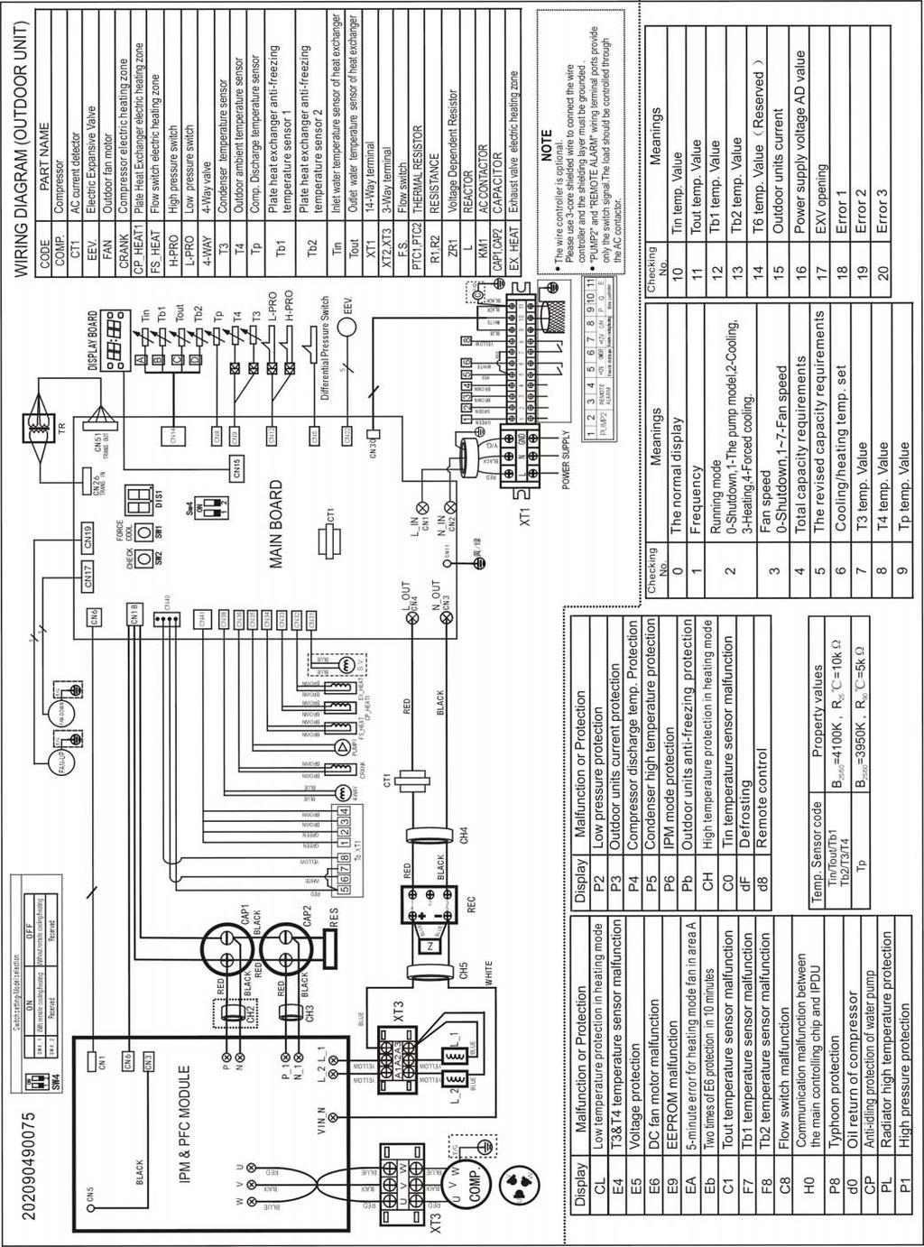
17 MUENR-10-H4 17

18 MUENR-12-H4 MUENR-14-H4 MUENR-16-H4 18
19 9. Electric Characteristics Model MUENR-05-H4 MUENR-07-H4 Outdoor Unit Supply Compressor OFM Hz Voltage Phase Min. Max. MCA TOCA MFA MSC RLA kw FLA 50 Hz V 1N 198 V 254 V 10,1 14, ,5 8,1 0,195 1,65 50 Hz V 1N 198 V 254 V 10,1 15, ,5 8,1 0,195 1,65 MUENR-10-H4 50 Hz V 1N 198V 264V MUENR-12-H4 50Hz 380~415V 3N 342V 456V MUENR-14-H4 MUENR-16-H4 50Hz 380~415V 3N 50Hz 380~415V 3N 342V 456V V 456V Remark: MCA: Min. Current Amps. (A) TOCA: Total Over-current Amps. (A) MFA: Max. Fuse Amps. (A) MSC: Max. Starting Amps. (A) RLA: Rated Current Amps. (A) OFM: Outdoor Fan Motor FLA: Full Load Amps. (A) kw: Rated Motor Output (kw) 19
20 10. Tables MUENR-05-H4 Cooling Ambient temp.( ) Chilled water outlet temp EER EER EER EER EER EER ( ) kw kw W/W kw kw W/ W kw kw W/W kw kw W/W kw kw W/W kw kw W/W Note: The inlet/outlet water temperature difference is 5 C. Heating Ambient temp.( ) Hot water outlet temp COP COP COP COP COP COP COP ( ) kw kw W/W kw kw W/W kw kw W/W kw kw W/W kw kw W/W kw kw W/W kw kw W/W Note: The inlet/outlet water temperature difference is 5 C. 20
21 Chilled water outlet temp. MUENR-07-H4 Cooling Ambient temp.( ) EER EER EER EER EER EER ( ) kw kw W/W kw kw W/ W kw kw W/W kw kw W/W kw kw W/W kw kw W/W Note: The inlet/outlet water temperature difference is 5 C. Heating Ambient temp.( ) Hot water outlet temp COP COP COP COP COP COP COP ( ) kw kw W/W kw kw W/W kw kw W/W kw kw W/W kw kw W/W kw kw W/W kw kw W/W Note: The inlet/outlet water temperature difference is 5 C. 21
22 MUENR-10-H4 Cooling Ambient temp.( ) Chilled water outlet temp EER EER EER EER EER EER ( ) kw kw W/W kw kw W/ W kw kw W/W kw kw W/W kw kw W/W kw kw W/W Note: The inlet/outlet water temperature difference is 5 C. Heating Ambient temp.( ) Hot water outlet temp COP COP COP COP COP COP COP ( ) kw kw W/W kw kw W/W kw kw W/W kw kw W/W kw kw W/W kw kw W/W kw kw W/W Note: The inlet/outlet water temperature difference is 5 C. 22
23 Chilled water outlet temp. MUENR-12-H4 Cooling Ambient temp.( ) EER EER EER EER EER EER ( ) kw kw W/W kw kw W/ W kw kw W/W kw kw W/W kw kw W/W kw kw W/W Note: The inlet/outlet water temperature difference is 5 C. Heating Ambient temp.( ) Hot water outlet temp COP COP COP COP COP COP COP ( ) kw kw W/W kw kw W/W kw kw W/W kw kw W/W kw kw W/W kw kw W/W kw kw W/W Note: The inlet/outlet water temperature difference is 5 C. 23
24 MUENR-14-H4 Cooling Ambient temp.( ) Chilled water outlet temp EER EER EER EER EER EER ( ) kw kw W/W kw kw W/ W kw kw W/W kw kw W/W kw kw W/W kw kw W/W Note: The inlet/outlet water temperature difference is 5 C. Heating Ambient temp.( ) Hot water outlet temp COP COP COP COP COP COP COP ( ) kw kw W/W kw kw W/W kw kw W/W kw kw W/W kw kw W/W kw kw W/W kw kw W/W Note: The inlet/outlet water temperature difference is 5 C. 24
25 Chilled water outlet temp. MUENR-16-H4 Cooling Ambient temp.( ) EER EER EER EER EER EER ( ) kw kw W/W kw kw W/ W kw kw W/W kw kw W/W kw kw W/W kw kw W/W Note: The inlet/outlet water temperature difference is 5 C. Heating Ambient temp.( ) Hot water outlet temp COP COP COP COP COP COP COP ( ) kw kw W/W kw kw W/W kw kw W/W kw kw W/W kw kw W/W kw kw W/W kw kw W/W Note: The inlet/outlet water temperature difference is 5 C. 25
26 11. Operation Limits C COOLING 46 O UTSID EAIR TEMPERATURE C DELIVERY WATER TEMPERATURE HEATING C 27 O UTSID EAIR TEMPERATURE DELIVERY WATER TEMPERATURE C a) Ethylene Glycol Solutions Water and ethylene glycol solutions used as a thermal vector in the place of water reduce the performance of the unit. Multiply the performance figures by the values given in the following table. Freezing point ( C) Percentage of ethylene glycol in weight 0 12% 20% 28% 35% 40% cpf cq cdp cpf: correction factor of heating/cooling capacity cq: correction factor of flow rate cdp: correction factor of pressure drop 26
27 Note: 1. During winter leaving the unit unused, please drain water out completely from unit if no anti-freeze were charged into pipeline, or keep power on (at standby or off status) and ensure that water is contained inside of unit. 2. When ambient temperature lower 5, running cooling mode must be charged antifreeze. Refers to upper parameters for the charged volume. b) Fouling Factors The performance data given refer to conditions with clean evaporator plates (fouling factor=1). For different fouling factors, multiply the figures in the performance tables by the coefficient given in the following table. Fouling factors Evaporator (m 2 C/W) f1 fk1 fx f1 correction factor of capacity fk1 power input correction factor of compressor fx1 correction factor of total power input 27
28 12. Water Pressure Drop MUENR-05-H4 MUENR-07-H4 MUENR-10-H4 28
29 MUENR-12-H4 MUENR-14-H4 29
30 MUENR-16-H4 30
31 13. Sound Level Outdoor Unit Micro 1.4m 1.0m Model MUENR-05-H4 MUENR-07-H4 MUENR-10-H4 MUENR-12-H4 MUENR-14-H4 Noise level (db(a)) MUENR-16-H4 60 Note: 1).High/low air flow of outdoor fan motor. 2). It is tested 1 meter away from the machine in a semi-anechoic room (sound pressure). 31


32 14. Exploded View Exploded view units 5 and 7 kw MUENR-05-H4 MUENR-07-H
33 14.2. Spare parts list unit 5 kw MUENR-05-H4 No. Description Qty. Supplier code Code 1 Welded parts of fixed plate Welded part of support Bearing base Fixed plate of inlet pipe Support bar of check valve Partition ass'y Compressor (Mitsubishi Electric SNB172FJGMC) CL Compressor electric heater Support ass'y of compressor Base plate parts Drain pipe adapter Hydraulic meter Water intlet temp.sensor ass'y (Tin) Water outlet temp.sensor ass'y (Tout) CL92484 Plate heat exchanger temp.sensor ass'y (Tb) Outlet water pipe ass'y Water charge valve Valve electric heater Safety valve Water flow switch (Interruptor de caudal) CL Inlet water pipe ass'y Exhaust valve Plate heat exchanger ass'y (Intercambiador de placas) Heat-exchanger electric heater EXV ass'y Liquid accumulator can Electronic expansion valve (Válvula de expansión electrónica) CL92365 / CL way valve ass'y way valve suite way valve Solenoid Pressure controller Meter connector Discharge temp sensor ass'y (Tp) CL Liquid receiver ass'y Accumulator cylinder Pressure controller Drain-pipe ass'y of plate heat exchanger Expansion vessel Clamp Shieled pump ass'y (Bomba de agua RS15/6-3-WILO) DC motor (Motor ventilador WZDK170-35G-1) CL Display cover ass'y Display box ass'y (Panel de control) CL Outdoor unit electric box ass'y PFC inductance IPM module ass'y (Placa inverter) CL Outdoor main control board ass'y (Placa principal) CL Transformer CL Wire joint Wire joint,6p supply board ass'y (Placa de potencia) CL Top cover parts Axial fan assy (Aspas ventilador) CL Front panel Outlet grille ass'y Condenser parts Room temp sensor ass'y (T4) CL92377 / CL Pipe temp.sensor ass'y (T3) CL92375 / CL Front clapboard ass'y Left supporting board Motor bracket Rear net frame Baffle ass'y
34 14.3. Spare parts list unit 7 kw MUENR-07-H4 No. Description Qty. Supplier code Code 1 Welded parts of fixed plate Welded part of support Bearing base Fixed plate of inlet pipe Support bar of check valve Partition ass'y Compressor (Mitsubishi Electric SNB172FJGMC) CL Compressor electric heater Support ass'y of compressor Base plate parts Drain pipe adapter Hydraulic meter Water intlet temp.sensor ass'y (Tin) Water outlet temp.sensor ass'y (Tout) CL92484 Plate heat exchanger temp.sensor ass'y (Tb) Outlet water pipe ass'y Water charge valve Valve electric heater Safety valve Water flow switch (Interruptor de caudal) CL Inlet water pipe ass'y Exhaust valve Plate heat exchanger ass'y (Intercambiador de placas) Heat-exchanger electric heater EXV ass'y Liquid accumulator can Electronic expansion valve (Válvula de expansión electrónica) CL92365 / CL way valve ass'y way valve suite way valve Solenoid Pressure controller Meter connector Discharge temp sensor ass'y (Tp) CL Liquid receiver ass'y Accumulator cylinder Pressure controller Drain-pipe ass'y of plate heat exchanger Expansion vessel Clamp Shieled pump ass'y (Bomba de agua RS15/6-3-WILO) DC motor (Motor ventilador WZDK170-35G-1) CL Display cover ass'y Display box ass'y (Panel de control) CL Outdoor unit electric box ass'y PFC inductance IPM module ass'y (Placa inverter) CL Outdoor main control board ass'y (Placa principal) CL Transformer CL Wire joint Wire joint,6p supply board ass'y (Placa de potencia) CL Top cover parts Axial fan assy (Aspas ventilador) CL Front panel Outlet grille ass'y Condenser parts Room temp sensor ass'y (T4) CL92377 / CL Pipe temp.sensor ass'y (T3) CL92375 / CL Front clapboard ass'y Left supporting board Motor bracket Rear net frame Baffle ass'y

35 14.4. Exploded view unit 10 kw MUENR-10-H
36 14.5. Spare parts list unit 10 kw MUENR-10-H4 No. Description Qty. Supplier code Code 1 Right-front plate ass'y Four-way valve parts Four-way valve ass'y Pressure switch Welded parts of base Suction pipe ass'y Pressure controller Liquid tank ass'y Fixed plate ass'y of compressor Compressor (GMCC ATQ420D1UMU) CL EXV ass'y Electronic expansion valve (Cuerpo válvula de expansión) CL92366 / CL Expansion valve wire (CAM-MD12GRSZ-5) Air release valve ass'y Exhaust valve Connection pipe ass'y Base Fixed plate of inlet/outlet pipe Connection pipe parts of water pump Water charge valve Safety valve Drain pipe adapter Water pump (Bomba de agua RL25/8,5) Coaming I Plate heat exchanger ass'y (Intercambiador de placas) Electrical heater of plate heat exchanger Plate heat exchanger Rubber gasket Coaming II Connection pipe ass'y of differential pressure valve Electrical heater of differential pressure valve Gas-liquid separator Differential pressure switch (Presostato diferencial de presión) Hydraulic meter Display box ass'y (Panel de control) CL Outdoor electrical control box ass'y Module board ass'y (Placa inverter) CL Radiator Terminal block, 3P Radiator Three phase bridge (Puente de diodos) CL Transformer CL Electrolytic capacitor Wire joints,12p Outdoor control board ass'y (Placa principal) CL Right back plate Inductance Box Ass'y PFC Inductor Condenser ass'y Coaming ass'y Bracket ass'y, net Installation plate of expansion tank Top cover ass'y Expansion vessel Rear-left supporting board Motor bracket assembly DC Motor (Motor ventilador WZDK100-38G) CL Axial fan assy (Aspas ventilador) CL Front Panel Net Handle Water intlet temp.sensor ass'y (Tin) Water outlet temp.sensor ass'y (Tout) Plate heat exchanger temp.sensor 1 ass'y (Tb1) CL92488 Plate heat exchanger temp.sensor 2 ass'y (Tb2) Room temp sensor ass'y (T4) CL92378 / CL94671 Pipe temp.sensor ass'y (T3) CL92375 / CL94639 Discharge temp sensor ass'y (Tp) CL
37 14.6. Exploded view units 12, 14 and 16 kw MUENR-12-H4 MUENR-14-H4 MUENR-16-H
38 14.7. Spare parts list unit 12 kw MUENR-12-H4 No. Description Qty. Supplier code Code 1 Right-front plate ass'y Four-way valve parts Four-way valve ass'y Pressure switch Welded parts of base Suction pipe ass'y Pressure controller Liquid tank ass'y Fixed plate ass'y of compressor Compressor (GMCC ATQ420D2UMU) CL EXV ass'y Electronic expansion valve (Cuerpo válvula de expansión) CL Expansion valve wire (CAM-MD12GRSZ-5) Air release valve ass'y Exhaust valve Connection pipe ass'y Base Fixed plate of inlet/outlet pipe Connection pipe parts of water pump Water charge valve Safety valve Drain pipe adapter Water pump (Bomba de agua RL25/8,5) Coaming I Plate heat exchanger ass'y (Intercambiador de placas) Plate heat exchanger Electrical heater of plate heat exchanger Rubber gasket Coaming II Connection pipe ass'y of differential pressure valve Electrical heater of differential pressure valve Gas-liquid separator Differential pressure switch (Presostato diferencial de presión) Hydraulic meter Display box ass'y (Panel de control) CL Outdoor electrical control box ass'y Module board ass'y (Placa inverter) CL Radiator Three phase bridge (Puente de diodos) CL Capacitor supply board (Placa de potencia) CL Resistance AC contactor wire joint Outdoor control board ass'y (Placa principal) CL Wire joint, 2p Terminal block, 3P Right back plate Inductance parts ass'y Reactance Condenser ass'y Coaming ass'y Bracket ass'y, net Installation plate of expansion tank Top cover ass'y Expansion vessel Left supporting board, rear Motor bracket assembly DC Motor (Motor ventilador WZDK100-38G) CL Axial fan assy (Aspas ventilador) CL Front Panel Grille Handle Water intlet temp.sensor ass'y (Tin) Water outlet temp.sensor ass'y (Tout) Plate heat exchanger temp.sensor 1 ass'y (Tb1) CL92488 Plate heat exchanger temp.sensor 2 ass'y (Tb2) Room temp sensor ass'y (T4) CL92378 / CL94671 Pipe temp.sensor ass'y (T3) CL92376 / CL94670 Discharge temp sensor ass'y (Tp) CL92483 / CL
39 14.8. Spare parts list unit 14 kw MUENR-14-H4 No. Description Qty. Supplier code Code 1 Right-front plate ass'y Four-way valve parts Four-way valve ass'y Pressure switch Welded parts of base Suction pipe ass'y Pressure controller Liquid tank ass'y Fixed plate ass'y of compressor Compressor (GMCC ATQ420D2UMU) CL EXV ass'y Electronic expansion valve (Cuerpo válvula de expansión) CL Expansion valve wire (CAM-MD12GRSZ-5) Air release valve ass'y Exhaust valve Connection pipe ass'y Base Fixed plate of inlet/outlet pipe Connection pipe parts of water pump Water charge valve Safety valve Drain pipe adapter Water pump (Bomba de agua RL25/8,5) Coaming I Plate heat exchanger ass'y (Intercambiador de placas) Electrical heater of plate heat exchanger Plate heat exchanger Rubber gasket Coaming II Connection pipe ass'y of differential pressure valve Electrical heater of differential pressure valve Gas-liquid separator Differential pressure switch (Presostato diferencial de presión) Hydraulic meter Display box ass'y (Panel de control) CL Outdoor electrical control box ass'y Module board ass'y (Placa inverter) CL Radiator Three phase bridge (Puente de diodos) CL Capacitor supply board (Placa de potencia) CL Resistance AC contactor wire joint Outdoor control board ass'y (Placa principal) CL Wire joint, 2p Terminal block, 3P Right back plate Inductance parts ass'y Reactance Condenser ass'y Coaming ass'y Bracket ass'y, net Installation plate of expansion tank Top cover ass'y Expansion vessel Left supporting board, rear Motor bracket assembly DC Motor (Motor ventilador WZDK100-38G) CL Axial fan assy (Aspas ventilador) CL Front Panel Grille Handle Water intlet temp.sensor ass'y (Tin) Water outlet temp.sensor ass'y (Tout) Plate heat exchanger temp.sensor 1 ass'y (Tb1) CL92488 Plate heat exchanger temp.sensor 2 ass'y (Tb2) Room temp sensor ass'y (T4) CL92378 / CL94671 Pipe temp.sensor ass'y (T3) CL92376 / CL94670 Discharge temp sensor ass'y (Tp) CL92483 / CL
40 14.9. Spare parts list unit 16 kw MUENR-16-H4 No. Description Qty. Supplier code Code 1 Right-front plate ass'y Four-way valve parts Four-way valve ass'y Pressure switch Welded parts of base Suction pipe ass'y Pressure controller Liquid tank ass'y Fixed plate ass'y of compressor Compressor (GMCC ATQ420D2UMU) CL EXV ass'y Electronic expansion valve (Cuerpo válvula de expansión) CL Expansion valve wire (CAM-MD12GRSZ-5) Air release valve ass'y Exhaust valve Connection pipe ass'y Base Fixed plate of inlet/outlet pipe Connection pipe parts of water pump Water charge valve Safety valve Drain pipe adapter Water pump (Bomba de agua RL25/8,5) Coaming I Plate heat exchanger ass'y (Intercambiador de placas) Electrical heater of plate heat exchanger Plate heat exchanger Rubber gasket Coaming II Connection pipe ass'y of differential pressure valve Electrical heater of differential pressure valve Gas-liquid separator Differential pressure switch (Presostato diferencial de presión) Hydraulic meter Display box ass'y (Panel de control) CL Outdoor electrical control box ass'y Module board ass'y (Placa inverter) CL Radiator Three phase bridge (Puente de diodos) CL Capacitor supply board (Placa de potencia) CL Resistance AC contactor wire joint Outdoor control board ass'y (Placa principal) CL Wire joint, 2p Terminal block, 3P Right back plate Inductance parts ass'y Reactance Condenser ass'y Coaming ass'y Bracket ass'y, net Installation plate of expansion tank Top cover ass'y Expansion vessel Left supporting board, rear Motor bracket assembly DC Motor (Motor ventilador WZDK100-38G) CL Axial fan assy (Aspas ventilador) CL Front Panel Grille Handle Water intlet temp.sensor ass'y (Tin) Water outlet temp.sensor ass'y (Tout) Plate heat exchanger temp.sensor 1 ass'y (Tb1) CL92488 Plate heat exchanger temp.sensor 2 ass'y (Tb2) Room temp sensor ass'y (T4) CL92378 / CL94671 Pipe temp.sensor ass'y (T3) CL92376 / CL94670 Discharge temp sensor ass'y (Tp) CL92483 / CL
41 15. Installation a) Installation of general information General warning 1. These units have been designed to chilled and hot water and must be used in applications compatible with their performance characteristics; these appliances are designed for residential or similar applications. 2. Incorrect installation, regulation and maintenance or improper use absolves the manufacturer from all liability, whether contractual or otherwise, for damage to people, animals or things. Only those applications specifically indicated in this list are permitted. 3. Read this manual carefully. All work must be carried out by qualified personnel in conformity with legislation in force in the country concerned. 4. The guarantee is invalidated if the above instructions are not respected and if the unit is started up for the first time without the presence of personnel authorized by the Company (where specified in the supply contract) who should draw up a start-up report. 5. The documentation supplied with the unit must be consigned to the owner who should keep it carefully for future consultation in the event of maintenance or service. 6. All repair or maintenance work must be carried out by the Company s Technical Service or qualified personnel following the instructions in this manual. The air-conditioner must under no circumstances be modified or tampered with as this may create situations of risk. Failure to observe this condition absolves the manufacturer of all liability for resulting damage. Fundamental safety rules When operating equipment involving the use of electricity and water, a number of fundamental safety rules must be observed, namely: Prohibition 1. This appliance is not intended for use by persons (including children) with reduced physical, sensory or mental capabilities, or lack of experience and knowledge, unless they have been given supervision or instruction concerning use of the appliance by a person responsible for their safety. 2. Do not touch the unit with bare feet or with wet or damp parts of the body. 3. Do not carry out cleaning operations without first disconnecting the system from the electricity supply. 4. Do not modify safety or regulation devices without authorization and instructions from the manufacturer. 5. Do not pull, detach or twist the electrical cables coming from the unit, even when disconnected from the mains electricity supply. 6. Do not open doors or panels providing access to the internal parts of the unit without first ensuring that the mains switch is in the off position. 7. Do not introduce pointed objects through the air intake and outlet grills. 8. Do not dispose of, abandon or leave within reach of children packaging materials (cardboard, staples, plastic bags, etc.) as they may represent a hazard. Important 1. The chiller appliances are supplied without the main switch. The power supply to the unit must be disconnected using a suitable main switch that must be supplied and installed by the installer. 2. Respect safety distances between the unit and other equipment or structures. Guarantee adequate space for access to the unit for maintenance and/or service operations. supply: the cross section of the electrical cables must be adequate for the power of the unit and the power supply voltage must correspond with the value indicated on the respective units. All units must be earthed in conformity with legislation in force in the country concerned. 3. Hydraulic connections should be carried out as indicated in the instructions to guarantee correct operation of the unit. Empty the water circuit or add glycol if the unit is not used during the winter. Handle the unit with the utmost care to avoid damage. 41
42 b) Installation of outdoor unit Choice of installation site Before installing the unit, agree with the customer the site where it will be installed, taking the following points into consideration: - check that the fixing points are adequate to support the weight of the unit. - pay scrupulous respect to safety distances between the unit and other equipment or structures to ensure that air entering the unit and discharged by the fans is free to circulate. Positioning Before handling the unit, check the capacity of the lifting equipment used, respecting the instructions on the packaging. To move the unit in the horizontal, make appropriate use of a lift truck or similar, bearing in mind the weight distribution of the unit. To lift the unit, insert tubes long enough to allow positioning of the lifting slings and safety pins in the feet on the unit. To avoid the slings damaging the unit, place protection between the slings and the unit. Position the unit in the site indicated by the customer. Place either a layer of rubber (min. thickness 10 mm) or vibration damper feet (optional) between the base and support surface. Fix the unit, making sure it is level and that there is easy access to hydraulic and electrical components. If the site of installation is exposed to strong winds, fix the unit adequately to the support surface using tie rods if necessary. If a heat pump unit is being installed, make sure the condensate is drained using the drain hose supplied as standard. Prevent leaves, branches or snow from accumulating around the unit. These could reduce the efficiency of the unit. 42
43 >2000 >60cm Mini Chiller DC Inverter MUENR-H4 c) Installation space (units: mm) Since the gravity center of the unit is not at its physical center, so please be careful when lifting it with a sling. Never hold the inlet of the outdoor unit to prevent it from deforming. Do not touch the fan with hands or other objects. Do not lean it more than 45, and do not lay it sidelong. Make concrete foundation according to the specifications of the outdoor units. Fasten the feet of this unit with bolts firmly to prevent it from collapsing in case of earthquake or strong wind. Fix with bolt Single unit installation (Wall or obstacle) Air inlet >300 Air inlet >300 Maintain channel >600 Air outlet Parallel connect two units or above >300 >600 >2000 Parallel connect the front with rear sides >2000 >500 >3000 >3000 >300 All the pictures in this manual are for explanation purpose only. They may be slightly different from the air conditioner you purchased (depend on model).the actual shape shall prevail. 43
44 d) Hydraulic connection The choice and installation of components is the responsibility of the installer who should follow good working practice and current legislation. Before connecting the pipes, make sure they do not contain stones, sand, rust, or others which might damage the unit. Construction of a bypass is recommended to enable the pipes to be washed through without having to disconnect the unit (see drain valves). The connection piping should be supported in such a way as to avoid it weighing on the unit. It is recommended that the following devices are installed in the water circuit of the evaporator. A hydraulic safety valve shall be mounted in water system, which should open constantly. 1). Connecting drawing of pipeline system Units 5 and 7 kw: Factory connections F Installer connections 6 T 6 4 T WATER INLET WATER OUTLET 1 Pressure gauge 2 Vibration damper joint 3 Gate valve 4 Calibrating valve 5 Water flow switch 6 Thermometer 7 Pump 8 Safety valve 9 Air vent 10 Expansion tank 11 Mesh filter 12 Auto-water replenishing 13 Temperature sensor 14 Drain/chemical washing valve 15 Plate heat exchanger 16 Additional pump Units 10 to 16 kw: Factory Connections 3 Site Connections 4 A WATER INLET F WATER OUTLET Plate Heat Exchange 2 Differential Pressure Switch 3 Automatic Discharge Valve 4 Expansion Tank 5 Auto-watet replenishing 6 Circulating Pump 7 Pressure Gauge 8 Safety Valve 9 Drain/ChemicalWashing Valve 10 Flexible Joint 11 Thermometer 12 Calibrating Valve 13 Y-shaped Filter 14 Water Flow Switch 44
45 If the installation requires a useful head higher than that obtained by installing a pump assembly and storage tank, it is recommended that an additional pump is installed on the unit. Provided the additional pump installed inside of unit, the pump must connected close to plate heat exchanger. Provided the pump installed outside of unit, the pump shall be connected at water pipe s outlet. The pump can be easily installed on the unit by removing the pump connection pipe. Connect to terminal PL,PN on the electric panel. Important 1) The chillers must be provided with a filling/top-up system connected to the return line and a drain cock in the lowest part of the installation. Installations containing anti-freeze or covered by specific legislation must be fitted with hydraulic disconnections. 2) The manufacturer is not liable for obstruction, breakage or noise resulting from the failure to install filters or vibration dampers. Particular types of water used for filling or topping up must be treated with appropriate treatment systems. For reference values, see the table. e).design of the store tank in the system kw is the unit for cooling capacity, L is the unit for (G) minimum water flow volume in the formula. Comfortable type air conditioner G= cooling capacity 2.6L Process type cooling G= cooling capacity 7.4L In certain occasion (especially in manufacture cooling process), for conforming the system water content requirement, it s necessary to mount a tank equipping with a cut-off baffle at the system to avoid water short-circuit, Please see the following schemes: Error Recommendation Error Recommendation f).chilled water flow Minimum chilled water flow The minimum chilled water flow is shown in the below table. If the system flow is less than the minimum unit flow rate, the evaporator flow can be recalculated, as shown in the diagram. 45
46 For minimum chilled water flow rate Evaporator For maximum chilled water flow rate Evaporator Recirculation Recirculation Maximum chilled water flow The maximum chilled water flow is limited by the permitted pressure drop in the evaporator. It is provided in the below table. If the system flow is more than the maximum unit flow rate, bypass the evaporator as shown in the diagram to obtain a lower evaporator flow rate. Minimum and maximum water flow rates Item Water flow rate(m 3 /h) Model Minimum Maximum MUENR-05-H MUENR-07-H MUENR-10-H MUENR-12-H MUENR-14-H MUENR-16-H g). Design of expansion tank If a closed expansion tank with its filled volume of air is too small, the system pressure will easily exceed the maximum allowable pressure and cause water to discharge from the pressure relief valve, thus wasting water. If the closed tank is too large, when the water temperature drops, the system pressure may decrease to a level below the minimum allowable value and cause trouble in the air vent. Therefore, accurate sizing of a closed expansion tank is essential. For diaphragm expansion tanks, the minimum volume of the water tank, Vt, gal(m3),can be calculated by the following formula, recommended by ASHRAE Handbook 1996, HVAC Systems and Equipment: T 1 =lower temperature, o F ( ) T 2 =higher temperature, o F ( ) V t =V s v 2 /v 1-1-3α(T 2 -T 1 ) 1-p 1 /p 2 V s =volume of water in system, gal(m 3 ) p 1 =absolute pressure at lower temperature,psia(kpa abs.) p 2 =absolute pressure at higher temperature,paia(kpa abs.) v 1,v 2 =specific volume of water at lower and higher temperature, respectively, ft 3 /lb(m 3 /kg) α=linear coefficient of thermal expansion; for steel, α=6.5x10⁻⁶ in./in of(1.2x10⁻⁵ per ); for copper, α=9.5x10⁻⁶ in./in of(1.7x10⁻⁵ per ) In a chilled water system, the higher temperature T2 is the highest anticipated ambient temperature when 46
47 the chilled water system shuts down during summer. The lower temperature in a heating system is often the ambient temperature at fill conditions(for example, 50 o F or 10 ). h). Water quality control When industrial water is used as chilled water, little furring may occur; however, well water or river water, used as chilled water, may cause much sediment, such as furring, sand, and so on. Therefore, well water or river water must be filtered and softened in softening water equipment before flowing into chilled water system. If sand and clay settle in the evaporator, circulation of chilled water may be blocked, and thus leading to freezing accidents; if hardness of chilled water is too high, furring may occur easily, and the devices may be corroded. Therefore, the quality of chilled water should be analyzed before being used, such as PH value, conductivity, concentration of chloride ion, concentration of sulfide ion, and so on. PH 6-8 Total hardness Electrical conductivity Sulfide ion Chlorine ions Ammonia ions Sulfate ion Silicon Total iron Sodium ion Calcium ion less than 50 ppm less than 200 mv/cm (25 C) none less than 50 ppm none less than 50 ppm less than 30 ppm less than 0.3 ppm No requirement less than 50 ppm Filling the installation - Before filling, check that the installation drain cock is closed. - Open all installation and terminal air vents. - Open the gate valves. - Begin filling, slowly opening the water filling cock outside the unit. - When water begins to leak out of the terminal air vent valves, close them and continue filling until the pressure gauge indicates a pressure of 1.5 bars. Emptying the installation - Before emptying, place the mains switch in the off position. - Make sure the installation fill/top-up water cock is closed. - Open the drain cock outside the unit and all the installation and terminal air vent valves. 47
48 Size and position of connections Units 5 and 7 kw: water inlet auto-water replenishing orifice security discharge water outlet C F B G D Water outlet of plate heat exchanger Units 10 to 16 kw: A E H Model A (mm) B (mm) C (mm) D (mm) E (mm) F (mm) G (mm) H (mm) Water inlet/outlet (Ø) Auto-water replenishing (Ø) Security discharge (Ø) MUENR-05-H4 MUENR-07-H R1 G1/2 G1/ R1 G1/2 G1/2 auto-water replenishing orifice water outlet water inlet security discharge A B C D E F Model MUENR-10-H4 MUENR-12-H4 MUENR-14-H4 MUENR-16-H4 A (mm) B (mm) C (mm) D (mm) E (mm) F (mm) Water inlet/outlet (Ø) Auto-water replenishing (Ø) Security discharge (Ø) R5/4 G1/2 G1/2 Important a) The installation must be filled to a pressure of between 1 and 2 bars. b) It is recommended that this operation be repeated after the unit has been operating for a number of hours. The pressure of the installation should be checked regularly and if it drops below 1 bar, the water content should be topped-up. c) Check the hydraulic tightness of joints. d) An all-pole disconnection device which has at least 3mm separation distance in all pole and a residual current device (RCD) with the rating of above 10mA shall be incorporated in the fixed wiring according to the national rule the appliance shall be installed in accordance with national wiring regulations. e) If the fluid in the circuit contains anti-freeze, it should not be allowed to drain freely as it is pollutant. It should be collected for possible reuse. When draining after heat pump operation, take care as the water may be hot (up to 50 ). 48
49 i). Electrical connection The unitary mini chillers leave the factory already wired, and require the installation of an omni polar thermal overload switch, a lockable mains disconnecting switch for the connection to the mains power supply, and the connection of the flow switch to the corresponding terminals. All the above operations must be carried out by qualified personnel in compliance with the legislation in force. For all electrical work, refer to the electrical wiring diagrams in this manual. You are also recommended to check that the characteristics of the mains electricity supply are adequate for the absorptions indicated in the electrical characteristics table below, also bearing in mind the possible use of other equipment at the same time. Important to the unit must be turned on only after installation work (hydraulic and electrical) has been completed. All electrical connections must be carried out by qualified personnel in accordance with legislation in force in the country concerned. Respect instructions for connecting phase, neutral and earth conductors. The power line should be fitted upstream with a suitable device to protect against short-circuits and leakage to earth, isolating the installation from other equipment. Voltage must be within a tolerance of ±10% of the rated power supply voltage for the unit (for three phase units, the unbalance between the phases must not exceed 3%).If these parameters are not respected, contact the electricity supply company. For electrical connections, use double insulation cable in conformity with current legislation in the country concerned. An omnipolar thermal overload switch and a lockable mains disconnecting switch, in compliance with the CEI-EN standards (contact opening of at least 3mm), with adequate switching and residual current protection capacity based on the electrical data table shown below, must be installed as near as possible to the appliance. The devices on the unit must be lockable. An efficient earth connection is obligatory. Failure to earth the appliance absolves the manufacturer of all liability for damage. Do not use water pipes to earth the unit. Electrical Panel The electrical panel is located inside the unit at the top of the technical compartment where the various components of the refrigerant circuit are also to be found. To access the electrical panel, remove the front panel of the unit by undoing the screws. 5/7kW 10~16kW 49
50 j) Electrical Connection Units 5 and 7 kw : Cable Supply Outdoor units L N GND Residual Current CIrcuit-breaker For the functional connection of the unit, bring the power supply cable to the electrical panel inside the unit and connect it to terminals L-N and respecting the (L) phase, (N) neutral and earth in the case of single phase units ( V~50Hz). Unit 10 kw : N GND L PUMP2 Remote alarm Remote shutdownremote cooling/heating wire controller L N GND Residual Current Circuit-breaker L N GND AC V 50Hz TE: The outdoor units must be installed with an Residual Current Circuit-breaker near the power supply and must be effectively earthed. 50
51 Units 12 to 16 kw : A B N GND C PUMP2 Remote alarm Remote shutdown Remote cooling/heating wire controller A B C N GND Residual Current Circuit-breaker A B C N GND AC V 50Hz Auxiliary Connection 1) Units 5 and 7 kw : L 1 PUMP2 BOIL ON/OFF L N L N 220~240 V 220~240 V AC CANTACTOR Addtitiona l pump Reserved Switch 1. PUMP2 wiring terminal supplies ON/OFF signals only. Standby water pump must be controlled by the AC contactor. 2. ON/OFF wiring terminal L supplies 220V voltage. The unit must be powered off when connecting the remote control switch. When the remote control switch is closed, the unit is forced to shut down. 51
52 2) Units 10 to 16 kw : a. Additional pump Main control board 1 2 L N L N V V A1 AC contactor A2 Additional pump PUMP2 terminal only provides passive switching signal. Additional water pump must be controlled by the AC contactor. b. Remote alarm Main control board 3 4 Remote alarm terminal only provides passive switching signal. Current passing through the terminal interface should less than 1.5A, otherwise please use AC contactor to control load indirectly. c. Remote shutdown 5 6 SWITCH If switch is closed, the unit will be stopped forcibly. Under this circumstance, anti-frozen protection and other protection functions are still effective. If switch breaks, unit can run normally according settings. 52
53 d. Remote cooling/heating 7 8 SWITCH 2 If switch 2 is closed, the unit will shift to heating mode forcibly; If switch 2 breaks, the unit will shift to cooling mode forcibly. Note: Remote shutdown and Remote cooling/heating is optional function. Choose this function by DIP switch SW4_1(SW3_1 for 12/14/16kW) on PCB board. Factory default has no remote cooling/heating. When the remote control and wired controller used at the same time, the unit will carry out the last command of arbitrary terminal. Remote shutdown has the highest priority. In the status of remote shutdown, other controllers can t start the unit. e. Remote controller P Q E The wired controller is optional. Please use 3-core shielded wire to connect the wired controller and the shielding layer must be grounded. When connecting wired controller, outdoor unit control panel is mainly used for display which can check parameters and inquiry, can t be used to set mode and temperature.. The Specification of : Model MUENR-05-H4 MUENR-07-H4 MUENR-10-H4 MUENR-12-H4 MUENR-14-H4 MUENR-16-H4 (V/Ph/Hz)) 220~240/1/50 220~240/1/50 220~240/1/50 380~415/3/50 380~415/3/50 380~415/3/50 Circuit breaker/fuse (A) 25/20 30/25 40/35 30/25 30/25 30/25 wire (mm 2 ) Ground wire (mm 2 ) Important The power cord type designation is H07RN-F. Connecting cable between indoor unit and outdoor unit shall be approved poly-chloroprene sheathed flexible cord, type designation H07RN-F or heavier cord. The means for disconnection from a power supply shall be incorporated in the fixed wiring and have an air gap. 53
54 16. Checking and Starting Up the Unit Preparing for first start up Restarting after shutting down for long periods The chiller must be started up for the first time by the Technical Service. Before starting up the chillers, make sure that: - All safety conditions have been respected. - The chiller is adequately fixed to the surface it rests on. - Functional distances have been respected. - Hydraulic connections have been carried out as indicated in the manual. - The water circuit is filled and vented. When draining after heat pump operation, take care as the water may be hot. - The water circuit valves are open. - Electrical connections have been carried out correctly. - Voltage is within a tolerance of 10% of the rated voltage for the unit. - The unit is correctly earthed. - All electrical and hydraulic connections are tight and have been completed correctly. - Use grommet A for the electrical power cable and grommet B for the other external wires. A B To complete the electrical connections: - Remove the inspection panel by unscrewing the five screws. For example, MGC-V5W/D2N1 model. 54
55 3 1 2 set 3 To access the control panel, open the door: -remove the screw 1 and screw 2; -lift the door 3. 55
56 17. Running and Maintenance a) Operating characteristics Set point in cooling mode (factory set) = 12 C, Hysteresis = 3 C. The compressor starts with water temperatures above 12 C. The compressor shuts down with water temperatures of less than 9 C. Set point in heating mode (factory set) = 40 C, Hysteresis = 4 C. The compressor starts with water temperatures below 38 C. The compressor shuts down with water temperatures above 42 C. In the event of a temporary power failure, when power returns, the mode set previously will be retained in the memory. Compressor start up delay Two functions prevent the compressor from starting up too frequently - Minimum time since last start-up 300 seconds. Pump The electronic board includes a pump control output. The pump starts when the assembly is powered up and at least 285 seconds before the compressor starts up and stops 120 seconds after the assembly shuts down. After the first 120 seconds of pump operation when the water flow is at full speed, the water flow alarm functions are activated (differential pressure switch and flow switch). With a pump connected to terminals PL and PN on the installer terminal board. Fan speed control For correct operation of the unit with different outside temperatures, the microprocessor controls the fan speed based on the pressure reading from the pressure probe, thus enabling heat exchange to be increased and/or decreased, maintaining the condensing or evaporation temperature practically constant. The fan functions independently of the compressor. Frost prevention alarm To prevent the water freezing and damaging the plate heat exchanger, the microprocessor shuts down the compressor if the temperature measured by the heat exchanger outlet temperature sensor is less than 3 C. The frost prevention temperature set point can be modified by an authorized service center only and only after verifying that the water circuit contains antifreeze. Tripping of this alarm shuts down the compressor but not the pump, which remains active. To reset normal functions, the outlet water temperature must rise to more than +15 C. Reset is manual. Water flow alarm The microprocessor provides for management of a water flow alarm controlled by a differential pressure switch fitted as standard on the appliance to be installed on the water delivery piping. This safety device may trip after the first 120 seconds of pump operation when the water flow is up to speed. Tripping of this alarm shuts down the compressor but not the pump, which remains active. To reset normal functions, the alarm contact must be deactivated for at least 15 seconds. When electrical current exceeds to setting value and condenser temperature over than 62 C, system will shut down, but not returns to normal operation until the condenser temperature decreased less than 52 C. 56
57 b) Routine maintenance Never perform any cleaning operations before having disconnected the unit from the mains power supply. If the supply cord is damaged, it must be replaced by the manufacturer or its service agent or a similarly qualified manufacturer or its service agent or a similarly qualified. Regular maintenance is fundamental to maintain the efficiency of the unit both in terms of operation and energy consumption. The Technical Assistance Service maintenance plan must be observed, with an annual service which includes the following operations and checks: - Filling of the water circuit. - Presence of air bubbles in the water circuit. - Efficiency of safety devices. - supply voltage. - input. - Tightness of electrical and hydraulic connections. - Condition of the compressor contactor. - Efficiency of the plate heat exchanger heater. - Checking of operating pressure, superheating and sub cooling. - Efficiency of compressor heater. - Cleaning of finned coil (*). - Cleaning of fan grills. - Cleaning of condensate drain pan (if installed). (*) For Heat pump appliances, the checks are to be performed quarterly. For units installed near the sea, the intervals between maintenance should be halved. c) Extraordinary maintenance Never perform any cleaning operations before having disconnected the unit from the mains power supply. Chemical washing You are recommended to chemically wash the plate heat exchanger after every 3 years of operation. Refrigerant gas content The chillers are filled with R410a refrigerant gas and tested in the factory. In normal conditions, there should be no need for the Technical Assistance Service to intervene to check the refrigerant gas. However, over time, small leaks may develop at the joints leading to loss of refrigerant and draining of the circuit, causing the unit to function poorly. In this case, the leaks of refrigerant must be identified and repaired and the refrigerant circuit refilled. Proceed as follows: - Empty and dry the entire refrigerant circuit using a vacuum pump connected to the low and high pressure tap until the vacuum meter reads about 10Pa. Wait a couple of minutes and check that this value does not rise to more than 200Pa. - Connect the refrigerant gas cylinder or a filling cylinder to the low pressure line pressure gauge connection. - Fill with the quantity of refrigerant gas indicated on the rating plate of the unit. - Always check the superheating and sub cooling values. In the nominal operating conditions for the appliance, these should be between 5 and 10 C and between 4 and 8 C respectively. - After a couple of hours of operation, check that the liquid indicator indicates circuit dry (dry-green). Important In the event of partial leaks, the circuit must be completely emptied before being refilled The R410a refrigerant must only be filled in the liquid state. Operating conditions other than nominal conditions may produce considerably different values. Seal testing or identification of leaks must only be carried out using R410a refrigerant gas, checking with a suitable leak detector. 57
58 Prohibition 1. The refrigerant circuit must not be filled with a refrigerant other than that indicated of specification. 2. The use of a different refrigerant may cause serious damage to the compressor. 3. Oxygen, acetylene or other inflammable or poisonous gases must never be used in the refrigerant circuit as they may cause explosion or poisoning. 4. Oils other than those indicated on manual before must not be used. The use of different oils may cause serious damage to the compressor. d) Shutting down for long periods If it is previewed not to use the machine for long periods After deactivating the chiller: -Make sure the model is in the power off model " ", or alternatively disconnect the unit from the power supply. -Make sure the remote control switch is closed (if present). -Close the water valves. Important If there is a possibility that the outside temperature may drop below zero, there is the risk of freezing. The water circuit MUST BE EMPTIED AND SHUT OFF POWER (when draining after heat pump operation take care as the water may be hot) or antifreeze must be added in the proportion recommended by the manufacturer. 58
59 18. Controller 18.1 Standard controller It is built-in with the chiller at the factory. The front panel of the device functions as the user interface and is used to perform all operations relating to the device Icon Description 1 Outside heat source running icon(reserved) 2 Cooling mode icon This icon will be constantly light when customers choose cooling mode. 3 Heating mode icon This icon will be constantly light when customers choose heating mode. 4 Water pump mode icon This icon will be constantly light when customers choose water pump mode. 5 Force cooling icon This icon will be constantly light when customers choose force cooling mode. 6 off icon This icon will be constantly light when customers choose off mode. 7.1 Clock icon, : flash once every 1s. It will display time when customers set the timer. The last 2 digits of the nixie tube icon. If is constantly light, it will display the current inlet water temperature. Its unit is.when customers do the water temperature setting, icon will 7.2 display the setting water temperature. When checking, will display the result of checking. When water heating is broken down or in protection, display the error code and protection code. Clock icon 8 It will display when finish setting the clock and be extinguished when the clock setting work is done. Timing on function icon 9 will flash when setting timing on. The icon will be constantly light when finish setting. Timing off function icon 10 will flash when setting timing off. The icon will be constantly light when finish setting. Breakdown light icon 11 When the unit is broken down or under protection, this icon will flash and will be off when malfunction and protection are eliminated. Compressor booting indicator icon 12 When booting the compressor, this icon will be constantly light. It will be off when the compressor is shut down E-heater booting indicator icon(reserved) 13 When booting the external E-heater, this icon will be constantly light. It will be off when the external E-heater is shut down. Fan booting indicator icon 14 When booting the fan, this icon will be constantly light. It will be off when the fan is shut down. Water pump booting indicator icon 15 When booting the water pump, this icon will be constantly light. It will be off when the water pump is shut down. 16 Key freezing icon 59
60 When freezing the keys, this icon will be constantly light. It will be off when unfreezing keys. Temperature unit icon When the control panel displays temperature, this icon will be constantly light. Current unit icon When the control panel displays current, this icon will be constantly light. Time format icon The unit is 12-hour format. will be constantly light when it is forenoon. will be constantly light when it is afternoon Frequency unit icon It will be constantly light when the control panel displays frequency of the compressor. ON/OFF and OK button 1.Long press for 3S will power on or off the controller. 2.Press to confirm the former operation when finishing the setting work. Mode choice function/function choice/back function button 1.Mode choice function. Choose operation mode. 2.Function choice. Long press it for 3s to enter function setting in the main interface.(clock setting, Timing on and timing off setting) 3.Back to the previous menu. Long press it for 3s to back to previous menu in the function setting interface. Top menu is the main interface. Up 1.(Value increase) 2.Forward to the previous interface. Down 1.(Value decrease) 2.Backward to the next interface Control panel operation description 1) ON/OFF The first time to powered on the unit, operation panel displays OFF. Long press for 3s, to unlock OFF status and enter into standby status. on: In the standby status, press to enter mode choice function. Press circularly to choose one kind of power on mode, the mode icon will flicker at the moment. Press to confirm the power on mode. The unit will run as the chosen mode when the mode icon will be constantly light. off: Press in the main interface to enter mode choice function and the icon which indicate the current mode will flicker. Press circularly to choose power off mode, will flicker at this moment. Press button to confirm the power off mode. By this time, will be constantly light and the unit stops. 2) Mode choice and temperature settings Press in the main interface to enter mode choice function. The Mode icon will flicker. Click circularly to choose a mode. The circulating order is Cooling mode Heating mode Water pump mode off mode Cooling mode. The chosen mode will flicker. Press or to increase/decrease the temperature in the chosen mode. Press to confirm power off mode and the set temperature. Mode icon will be constantly light and the unit will run as the chosen mode. Press or in the main interface to increase/decrease the temperature in the chosen mode. 3) Clock setting Long press for 3s to enter function interface. clock icon will flicker. Press to enter clock setting function. icon will be constantly light and the first 2 digits on nixie tube will flicker. Press or to set minute. Press when finish setting and will be extinguished. 4) Timing setting a. Timing on setting 1 Long press for 3s to enter function interface. clock icon will flicker. Press again to enter timing on function. will flicker and press to enter timing on setting. 60
61 2 At this moment, last 2 digits of the nixie tube display 01 which means the first group setting begins. Press to the next step. 3 By this time, mode icon will flicker and press to choose timing on mode. Press to confirm your choice and go to the next step. 4 By this time, the last 2 digits of the nixie tube will flicker and press or to adjust temperature and set the temperature of the inlet water. Press to confirm and move to the next step. 5 By this time, the first 2 digits of the nixie tube will flicker and press or to adjust time of timing on. Press to confirm and switch to minute setting automatically. The last 2 digits of the nixie tube will flicker and press or to adjust minute setting of timing on.(minimal unit of minute adjustment: 15 minutes). 6 Press to confirm. The first group setting is finished and will be constantly light. When processing the second timing setting, repeat the 1-2 operation above. When the nixie tube displays 01 and flicker, press or to choose the timing on group. When the nixie tube displays 02 which means setting timing on function of the second group. Refers the timing on setting operation of group 1 to set that of group 2. Long press for 3s to return to the previous interface to reset the parameter during setting clock timing. b. Timing off setting 1 Long press for 3s in the main interface to enter function interface. Press circularly to enter timing off function. will flicker and press to enter timing off setting. 2 At this moment, the last 2 digits of the nixie tube display 01 which means the first group setting begins. Press to the next step. 3 By this time, the first 2 digits of the nixie tube will flicker and press or to adjust time of timing off. Press to confirm and switch to minute setting automatically. The last 2 digits of the nixie tube will flicker and press or to adjust minute setting of timing off. Press to confirm. The first group setting is finished and will be constantly light. 4 When processing timing setting of group 2, repeat the 1-2 operation above. When the nixie tube displays 01 and flicker, press or to choose the timing off group. When the nixie tube displays 02 which means setting timing off function of the second group. Refers the timing off setting operation of group 1 to set that of group 2. c. Cancel all timing on/off settings Long press for 3s to enter function interface. clock icon will flicker and press to choose the timing function. and flicker simultaneously means choosing to cancel all timing functions. Press to cancel timing settings. and both will be extinguished Functions of combination key Force cooling function Press and simultaneously for 3s in the main interface to enter into force cooling mode. The force cooling mode icon will be constantly light. Press button and button simultaneously for 3s to quit force cooling mode. The unit will enter power off mode automatically when quitting force cooling mode. 61
62 Auto-lock(unlock) function If don t operate the controller in 60s, the keyboard will lock automatically. Press and simultaneously for 3s to unlock Factory Reset In main interface, long press Display panel will display OFF. for 3s, the unit will close and recovers to factory default mode. 62
 8.Clock 9.Water temp. 10.ON/OFF Key 11.Left Right Key 12.")

63 18.2 Optional wired controller (KJR-120F/BMK-E, KJR-120F1/BMK-E) (CL92340) Overview MODE FUNCTIONS (Press for 3sec to cancel timer) (Press for 3sec to unlock) Operation icon 2.Code area 3.Setting temperature 4.Timing On/Off 5.Function Icon 6.Unit number 7.Water Level Indication(reserved) 8.Clock 9.Water temp. 10.ON/OFF Key 11.Left Right Key 12.Confirm Key 13.Function key 14.Add and Reduce key 15.Cancel key 16.Mode key 1. Operation icon : Indicate unit ON and OFF status; the icon displays when the unit is on and does not display when the unit is off; 2. Mode area: Indicate the main unit operating mode; details refer to its manual; 3. Setting temperature: 2 status can be displayed: ; 4. Timing ON/OFF indication : Indicate the timing information; details refers to page 10 of the manual; 5. Function icon 63
64 1) : Displays when the unit controlled by remote switch; 2) : The conflict icon. 3) : Displays when the unit is needed. Press and hold MODE key for 3 seconds to cancel the icon and timing will restart until next maintenance; 4) : The reserved icon. ; 5) : The reserved icon. ; 6) : Displays when check function is on; details refers to the manual; 7) : Displays when ambient temperature is low which means the main unit need anti-freezing action; 8) : Displays when no key operation for 2 minutes and all keys are locked. Press and hold OK key for 3 seconds to unlock; 9) : Displays when error or protection occurs and means the unit need maintenance by professionals. 6The unit number: The user can set the number, details refer to page 16 of the manual; 7. Water level indication: The reserved icon; 8. Clock: Under normal status displays clock; Under timing setting displays the setting timing, details refer to page 15 of the manual; 9. Water temperature: Under normal status display water temperature; Under water temperature setting status displays the setting value; Under check status displays check parameter, details refer to Page 9, 18 of the manual; 10. ON/OFF key: Turn on and turn off functions, details refer to page 7 of the manual. 11. Right and Left key: Press these keys to check setting water temperature; Press right key to shift to the next step setting under timing setting status; Press these keys to turn over the unit parameter information under check status; 12. OK key: Press this key to confirm settings. Press and hold this key for 3 seconds to unlock under locking status; 13. Function key: Setting water temperature, timing and clock etc, details refer to Page 9-17; Press and hold this key for 3 seconds to enter check status, details refer to page 18 of the manual; 14. Add and Reduce key: Move up or move down values of temperature, timing etc; 15. Cancel key: Press this key to cancel parameter setting under setting status; Press and hold this key for 3 seconds to cancel timing when timing is valid; 16. Mode key: on the cooling function, heating function or water pump function, details refer to Page 8 of the manual. 64
65 Operation instructions a. Turn On and Turn Off the main unit 1) Press the On/Off key to control On and Off status of the main unit. 2) Under Off status, press the On/Off key to run the main unit, at that time the LCD of wired controller will display the operation icon. The main unit will running as the current setting of the wired controller. 3) Under On status, press the On/Off key to turn off the main unit and the operation icon on the LCD will disappear. RUN ONLINE QUANTIT Y WATER TEM P. TIMER MODE Press one time FUNCTIONS (Press for 3sec to cancel timer) (Press for 3sec to unlock) b. Setting operating mode and function parameters 1) Setting operating mode and water temperature Setting operating mode: Press MODE key to choose operation mode. The setting mode will change as the following order each time the key is pressed: Cooling Heating Water pump Press OK key or wait for 7 seconds to confirm. During the setting process pressing the CANCEL key to exit without saving. RUN WATER TEMP. TIMER MODE FUNCTIONS (Press for 3sec to cancel timer) (Press for 3sec to unlock) 65
66 2) Setting water temperature: Method 1:Press the or to adjust the water temperature after the controller is powered on. Press OK key or wait for 7 seconds to confirm. Method 2:Setting water temperature in parameters function. Press FUNCTIONS key under main interface once to enter water temperature setting interface. Press the or to adjust the water temperature.press OK key or wait for 7 seconds to confirm. RUN WATER TEMP. TIMER ON MODE Press once FUNCTIONS (Press for 3sec to cancel timer) (Press for 3sec to unlock) Water temperature setting check: To check the water temperature setting value, press the or under the main page(the page displayed after the controller is powered on). key c. Setting function parameters Press FUNCTIONS key to choose operation parameters. The setting function parameters will change as the following order each time the key is pressed: Water temperature Timing Clock Unit. Water pump forced 1) Timing setting: 3 timing periods can be set on the wired controller: Timer 1, Timer 2, Timer 3. These 3 timers can control the main unit to be turned ON and OFF 3 times at most during a day. 2) Setting method: press FUNCTIONS key under main page twice to enter timing setting. Then the LCD will display as the following: TIMER1 ON 66
67 RUN WATER TEMP. TIMER ON MODE Press twice FUNCTIONS (Press for 3sec to cancel timer) (Press for 3sec to unlock) At this time the hour of the clock will flash, which means the current setting is the hour of Timer 1 On, press the or to adjust, press key when finished, and then the minute of the clock will flash, which means the current setting is the minute of Timer 1 On, press the or to adjust, press key when finished, the LCD will display as the following: TIMER1 OFF At this time the hour of the clock will flash, which means the current setting is the hour of Timer 1 Off, press the or to adjust, press key when finished, and then the minute of the clock will flash, which means the current setting is the minute of Timing 1 Off, press the or to adjust, press key when finished, the LCD will display as the following: TIMER ON At this time the hour of the clock will flash, it means the current setting is the hour of the Timer 2 On. And the follow setting method will be the same as the Timer 1. Similarly, the setting of Timing 3 is the same as this method. After setting is finished, press OK key or wait for 7 seconds to confirm the setting, and the LCD will display the effective timing information, as the following display: TIMER 67
68 Example of Timing setting Main page Press FUNCTIONS key twice to enter hour setting interface of Timer 1 On Press the or key to set the hour number of Timing 1 On to be 07 Press key to enter minute setting interface of Timer 1 On, adjust the minute number to be 10 Press key to enter hour setting interface of Timer 1 Off, adjust the hour number of Timer 1 Off to be 12 Press key to enter minute setting interface of Timer 1 Off, adjust the minute number to be 30 Timer 1 setting failed, after 7 seconds, the page shift to the main page. No Whether press OK key Whether press key No Yes Successfully set the On time of Timer 1 to be 07:10 and Off time of Timer 1 Off to be 12:30, then back to the main page. Yes Finish setting the On time of Timer 1 to be 07:10 and Off time to be 12:30, then enter the setting of Timer 2. The setting steps of Timer 2 and Timer 3 are the same as Timer 1, after setting all the settings then press OK key, the 3 timing periods will be effective. During any period of timing setting to press OK key, the timing periods which have been set will be effective (only if the On and Off of one timing period have been set, the setting is effective). Check timing information: to check the timing which has been set, press or key under main page, the On and Off time of Timer1, Timer 2 and Timer3 will be displayed in turns. Cancel timing: press and hold CANCEL key for 3 seconds, then all the effective timing periods will be cancelled. Note: Correct: To avoid timing error, each period of timing should not be crossed. E.g.: Correct: TIMER 1 TIMER 2 TIMER 3 5:00 8:00 10:00 12:00 18:00 22:00 Wrong: TIMER 1 TIMER 2 5:00 7:00 8:00 12:00 68
69 d. Setting clock RUN WATER TEMP. TIMER ON MODE Press 3 times FUNCTIONS (Press for 3sec to cancel timer) (Press for 3sec to unlock) Press the FUNCTION key 3 times to enter clock setting. The hour of the clock will flash, which means the current setting is the hour of the clock, press the or to adjust, press key when finished, and then the minute of the clock will flash, it means the current setting is the minute of the clock, press the or to adjust, press OK key when finished or wait for 7 seconds to confirm. During the setting process pressing the CANCEL key to exit without saving. TE: To get the correct timing On and timing Off time, please correctly set the clock! e. Setting unit number RUN WATER TEMP. TIMER ON MODE FUNCTIONS Press 4 times (Press for 3sec to cancel timer) (Press for 3sec to unlock) Press the FUNCTIONS key 4 times to enter the unit number setting. Press or to adjust the unit number. press OK key when finished or wait for 7 seconds to confirm. During the setting process pressing the CANCEL key to exit without saving. The setting value is
70 f. Force opening water pump WATER TEMP. TIMER ON MODE Press 5 times FUNCTIONS (Press for 3sec to cancel timer) (Press for 3sec to unlock) Press the FUNCTIONS key 5 times to force open the water pump. The water pump icon will flash. Press OK key to confirm. During the setting process pressing the CANCEL key to exit without saving. Note: a. Forcing water pump function is only limited to stand-by mode, others modes not response. b. Under forcing water pump function, other settings will not responsible, except stopping c. When communication disconnects, it will show E2 error in 2 minutes, the wired controller will automatically cancel the forcing water pump function; while connected, the wired controller keeps synchronizing with the unit( If forcing water pump function is still on-going, the controller keeping showing its status). d. The outdoor unit does not response after activating the forcing water pump function, (eg: forcing water pump function cannot be activated under forcing heating in stand-by mode),the function will be automatically stopped if it is not activated within 5 minutes Checking function 1) Check function allows the user to check all the operating parameters, error and protection information of the unit. 2) Entering method: press and hold FUNCTIONS key for 3 seconds to enter check interface, as the figure display: check icon CHECK check parameter RUN Unit number check sequence number MODE Press 3 seconds FUNCTIONS (Press for 3sec to cancel timer) (Press for 3sec to unlock) 3) Press or to check all the status information of the unit. 70
71 Check content when wired controller setting is 1: (The checking content is the same as the PCB s checking.) Order Contents 1 Running mode: 0-shutdown,1-Pump mode,2-cooling,3-heating,4-forced cooling, 5-Forced heating. 2 Fan speed:0-shutdown,1~7-fan speed. 3 Total capacity requirements. 4 The revised capacity requirements. 5 Cooling/heating temp. setting. 6 T3 temperature value 7 T4 temperature value 8 Tp temperature Value 9 Tin temp. Value (Inlet water temperature) 10 Tout temp. Value (Outlet water temperature) 11 Tb1 temp. Value (Temperature 1 of heat plate) 12 Tb2 temp. Value (Temperature 2 of heat plate) 13 T6 temp. Value(Reserved ) 14 Outdoor unit current 15 supply voltage AD value 16 Electronic expansion valve opening steps 17 The unit model:10-10kw,12-12kw,14-14kw,16-16kw 18 The program version number 19 The last error cord 20 The second error cord 21 The first error cord
72 19.Troubleshooting 19.1 PCB parts instructions 1) Units 5 and 7 kw : PFC&IPM panel Input rectifier bridge port 1 2. Input rectifier bridge port 2 3. PFC inductance port 1 4. P-OUT 5. PFC inductance por 2 6. N-OUT 7. PFC control port V port 9. IPDU communication port 10. IPM power port N 11. Compressor connection port U/V/W 12. IPM power port P 10 72
73 Main control panel L 2. N 3. Preliminary charging relay (rectifier bridge input port 1) 4. Input rectifier bridge line (rectifier bridge input port 2) 5. 5A fuse 6. To IPDU 7. To PFC 8. Solenoid valve (Reserve) 9. Electric heater of plate heat exchanger 10. Electric heater of compressor 11. Pump 12. Electric heater of water flow switch way valve 14. Additional pump/boil (Reserve) 15. Transformer input 16. Electronic expansion valve 17. Remote control 18. DC fan power supply port 19. DC fan port 20. Tin/Tout/Tb1 temperature sensor 21. Radiator temperature sensor (Reserve) 22. Discharge temperature sensor (Tp) 23. Outlet of outdoor heat exchanger temperature sensor(t3) 24. Ambient temperature sensor(t4) 25. Low pressure switch 26. High pressure switch 27. Operation and display panel port 28. Water flow switch 29. Transformer output 1 73
74 DC filter panel IPM supply N 2. IPM supply P 3. PFC output power P 4. PFC output power N 5. DC 380V (DC fan power supply port) 74
75 2) Unit 10 kw : Main control panel Transformer output port 2. Tin/Tb1/Tout/Tb2 temperature sensor port Note: Tin: water inlet temperature Tout: water outlet temperature Tb1: Temperature 1 of plate heat exchanger Tb2: Temperature 2 of plate heat exchanger 3. Radiator temperature sensor port(reserved) (T6) 4. Discharge temperature sensor port 5.1 Outlet of outdoor heat exchanger temperature sensor port(t3) 5.2 Ambient temperature sensor port (T4) 6. Operation and display panel port 7.1 Low pressure switch 7.2 High pressure switch 8. Differential pressure valve port 9. Factory debug port 10. Wired controller port 11. Electric expansion valve port 12. supply input port L 13. supply input port N 14. Ground wire 75
76 15. Rectifier bridge input port N 16. Rectifier bridge input port L 17. 8A fuse tube 18. Solenoid valve port(reserved) 19. Exhaust valve electric heater port 21. Plate heat exchanger electric heater 22. Differential pressure valve electric heater port 23. Built-in water pump port 24. Compressor electric heater way valve port 26. External pump/remote alarm port 27. Transformer input port 38. P/N/+15V port 29. Communication port between IPDU and main PCB 30. Down DC fan port 31. Check touch switch 32. Up DC fan port 33. Force-cooling touch switch PFC Module
77 1. +18V output port 2. Input Port P for IPM 3. supply port U of the compressor 4. supply port V of the compressor 5. supply port W of the compressor 6. PFC output N 7. PFC output P 8. PFC inductance port L_1 9. PFC inductance port L_2 10. PFC input N 11. IPM input N 12. Communication port to main control board 3) Units 12 to 16 kw : Main control panel
78 1. Input port for switching power supply 2. Debugging port 3. Connection port for operation and display panel 4. Tin/Tb1/Tout/Tb2 temperature sensor port Note: Tin: water inlet temperature Tout: water outlet temperature Tb1: Temperature 1 of plate heat exchanger Tb2: Temperature 2 of plate heat exchanger 5. Discharged temperature sensor port (Tp) 6.1 T3 temperature sensor port 6.2 T4 ambient temperature sensor port 7.1. Low pressure switch 7.2 High pressure switch 8. Checking touch switch 9. Force-cooling touch switch 10. Differential pressure valve port 11. Factory debugging port 12. Wired controller port 13. AC Current transformer 14. Remote on/off and remote cooling/heating port 15. Electronic expansion valve port 16. AC 220V power supply port 17. Solenoid valve port(reserved) 18. Exhaust valve electric heater port 19. Electric heater port of Plate heat exchanger 20. Electric heater port of differential pressure valve 21. Built-in water pump port 22. Electric heater of the compressor 23. Precharge AC contactor port way valve port 25. External water pump/remote alarm port 26. Up DC fan port 27. Down DC fan port 28. supply port for switching power supply of PFC board 29. Drive module port 30. P/N/+15V port 78


79 IPM module V output port 2. communication port to main control board 3. IPM input port N 4. Compressor connection port W 5. Compressor connection port V 6. Compressor connection port U 7. IPM input P 8. supply port for switching power supply 79

80 Filter board supply port L3 2. supply port L2 3. input port L1 4. input port N 5. Ground wire 6. Loaded power supply port for main control board 7. supply port for main control board 8. output port L1 after filtering 9. output port L2 after filtering 10. output port L3 after filtering 11. Ground wire Function setting dial switches instructions For 5/7kW For 10kW 80

81 For 12-16kW Query function for the built-in controller a. To enter parameter checking function Press and simultaneously for 3s to enter into the interface of parameter checking function. At this moment, first 2 digits of the digital tube will display sequence number and the last 2 digits is specific parameters. Press or to query the relative parameters. b.quit parameter query function If there s no operation in 20s when enter the parameter query, it will quit automatically and return to the main interface. Press and simultaneously to quit parameter query manually. Query content table 5/7kW No. Content Note 1 Frequency Show inlet water temperature when the unit is in standby mode and water pump mode. Display operating frequency when the unit is in cooling mode and heating mode. When defrosting displays df. Pb displays when anti-freezing mode running. 2 Operating mode 0- off,1-water pump,2-cooling,3-heating,4-force cooling 3 Operating fan speed level 0 off (1-7) 4 The total required capacity before revised Actual value (Force cooling displays 5) 5 requirements after revised Actual value (Force cooling displays 5) 6 Temperature set Actual setting temperature under cooling or heating mode 7 T3 Actual value(outlet temperature of outdoor heat exchanger) 8 T4 Actual value(outdoor ambient temperature) 9 Tp Actual value(compressor discharged temperature) 10 Tin Actual value(water inlet temperature of plate heat exchanger) 11 Tout Actual value(water outlet temperature of plate heat exchangers) 12 Tb1 Actual value (Temperature 1 of plate heat exchangers) 13 Tb2 Actual value (Temperature 2 of plate heat exchangers(equals to Tb1 ) 14 T6 Reserved (Cooling fin surface temperature(reserved) 15 Operation current Actual value 16 supply voltage Actual AD value 17 EXV Opening degrees Actual value 8 18 Model 5kW:5; 7kW:7 19 Version number Err 1 The last one malfunction code 21 Err 2 The last second malfunction code 22 Err 3 The last third malfunction code 81
Aqua Mini Full DC Inverter Unitary Chiller 50Hz. Content
 MCAC-ATSM-2014-09 Content 1. Outdoor units lineup... 2 2. Nomenclature... 3 3.Features... 4 4. Description of main components... 8 5. Specifications... 10 6. Dimensions... 14 7. Piping Diagram... 15 8.
Contents. Part 1 General Information...2 Part 2 Outdoor units...7 Part 3 Installation...63 Part 4 Controller...79
 MCAC-TSM-2008-02 Contents Part 1 General Information...2 Part 2 Outdoor units...7 Part 3 Installation...63 Part 4 Controller...79 Contents i MCAC-TSM-2008-02 Introduction Introduction Midea Mini Unitary
1. Outdoor units lineup
 Content 1. OUTDOOR UNITS LINEUP... 2 2. NOMENCLATURE... 3 3. FEATURES... 4 4. DESCRIPTION OF MAIN COMPONENTS... 7 5. SPECIFICATIONS... 9 6. DIMENSIONS... 13 7. PIPING DIAGRAM... 14 8. WIRING DIAGRAM...
inverter mini chiller
 inverter mini chiller TRUST AIR CONDITIONING EQUIPMENT CO. Prepared By: Engineering & R & D Department. Shiraz- May 2017 Content 1. OUTDOOR UNITS LINEUP... 2 2. FEATURES... 3 3. DESCRIPTION OF MAIN COMPONENTS...
COMMERCIAL AIR CONDITIONERS. Aqua Mini Chiller 50/60Hz
 COMMERCIAL AIR CONDITIONERS Aqua Mini Chiller 50/0Hz Midea CAC (MCAC) As a key subsidiary of Midea Group, the Midea Central Air Conditioner (MCAC) business unit has emerged as a leading supplier of commercial
Mini unitary chiller. Mini unitary chiller
 Mini unitary chiller Mini unitary chiller Product description Features and benefits Description of main components Specification Operation limits Hydraulic performance Dimension Service space Piping diagram
Part 1 General Information... 1 Part 2 Outdoor Unit... 4 Part 3 Installation... 45
 Contents Part 1 General Information... 1 Part 2 Outdoor Unit... 4 Part 3 Installation... 45 The specifications, designs, and information in this book are subject to change without notice for product improvement.
Content. The specifications, designs, and information in this book are subject to change without notice for product improvement.
 MCAC-ATSM-2014-01 Content R410A Mini Split Chiller 50Hz 1. Model Names of Outdoor Units... 2 2. External Appearance... 2 3. menclature... 3 4. Features... 4 5. Descriptions of Standard Unit... 6 6. Specifications...
Midea R410A Tropical ClimaCreator Series Rooftop Package 220V 3Ph 60Hz Technical Manual
 Midea R410A Tropical ClimaCreator Series Rooftop Package 220V 3Ph 60Hz Technical Manual Midea reserves the right to discontinue, or change specification or designs at any time without notices and without
UCV CONDENSING UNITS SPECIFICATIONS 1. Specifications
 UCV CONDENSING UNITS SPECIFICATIONS 1. Specifications Model UCV-76C UCV-96C Code 220075900040 220075900020 Power supply V- Ph-Hz 380-415~3~50 Capacity Btu/h 76000 96000 Cooling Input W 8100 10000 Rated
Air Cooled Scroll Chiller
 Air Cooled Scroll Chiller Midea chillers use H shape heat at air side and single unit s capacity from kw to 0kW. Super chillers are divided to SS,SS-LA, SP-LA and SP-HMLA series according to their water
Product Data. Features/Benefits. 30RQ Air-cooled Modular Chiller R22 & R410A & R407C
 Product Data 30RQ Air-cooled Modular Chiller R22 & R410A & R407C Introduction Air-cooled modular chiller is a kind of central airconditioning unit which adopts air as the cooling (or heating) source and
R22 air-cooled modular chiller 50Hz unit. Content
 Content 1.Nomenclature... 2 2.Product Schedule... 2. External Appearance... 4.Features... 4 5.Specification... 6 6.Dimension... 10 7.Refrigeration System Sketch Drawing... 14 8.Wiring Diagrams... 16 9.Electric
Technical Support Division GD CHIGO HEATING & VENTILATION EQUIPMENT CO., LTD.
 Technical Support Division 2017-4-25 New CMV System - Floor ceiling Indoor Unit 1 1. External appearance 2. Nomenclature 3. Specifications 4. Dimensions 5. Service space 6. Piping diagram 7. Wiring diagram
Part 1 General Information... 1 Part 2 Indoor Units... 7 Part 3 Outdoor Units Part 4 Installation Part 5 Control...
 MCAC-UTSM-2008-11 Contents Part 1 General Information... 1 Part 2 Indoor Units... 7 Part 3 Outdoor Units... 88 Part 4 Installation... 127 Part 5 Control... 136 The specifications, designs, and information
Mini Spilt Chiller &Mini Unitary Chiller 50Hz 2012
 MCAC Mini Spilt Chiller &Mini Unitary Chiller Hz Coercial Air Conditioner Business Units Midea Air Conditioning and Refrigeration Sector Add: est region of Midea coercial air conditioner department, Industry
[U] Serie MOV. Manual de Ingeniería
![[U] Serie MOV. Manual de Ingeniería](/thumbs/82/86228730.jpg "[U] Serie MOV. Manual de Ingeniería") [U] Serie MOV Uniidades Condensadoras (Fllujjo Verttiicall) 6..3,, 8 y 12..5 Ton Manual de Ingeniería - 112- Outdoor Units_MOV 1. Specifications.... 2. Dimension... 3. Service Space. 4. Piping Diagrams
[U] Serie MOV Uniidades Condensadoras (Fllujjo Verttiicall) 6..3,, 8 y 12..5 Ton Manual de Ingeniería - 112- Outdoor Units_MOV 1. Specifications.... 2. Dimension... 3. Service Space. 4. Piping Diagrams
DC Inverter Multi-split System Technical Manual - 50Hz/R410a
 DC Inverter Multi-split System Technical Manual - 50Hz/R410a A/1/LCAC/2/TM/1.0/201111 Content Contents Part 1. General Information... 1 1. Features... 1 2. Nomenclature... 3 3. Products Line-up... 5 4.
MANUAL DE INGENIERIA. Part 1 General Information... 1 Part 2 Indoor Units... 6 Part 3 Outdoor Units... 30
 MANUAL DE INGENIERIA Evaporadora Sopladora 'MVA' con Condensadora 'MOV' - Blue Star Part 1 General Information... 1 Part 2 Indoor Units... 6 Part 3 Outdoor Units... 30 Part 1 General Information 1. Model
Technical Manual. R410A 50Hz Universal Outdoor Series Inverter type. R410A50Hz Universal Outdoor Series Technical Manual LCAC/2016.
 Outdoor Unit R410A 50Hz Universal Outdoor Series Inverter type Technical Manual LCAC/2016.1 I GD Chigo Heating & Ventilation Equipment Co., Ltd. Content Part 1. General Information... 1 1. Nomenclature...
Content. Part 1 General Information Part 2 Indoor Units Part 3 Outdoor Units Part 4 Installation Part 5 Control...
 R410A Tropical Split Type AC Technical Manual Content Content Part 1 General Information... 2 Part 2 Indoor Units... 6 Part 3 Outdoor Units... 88 Part 4 Installation... 120 Part 5 Control... 154 Indoor
SLS 1202 to With or without total heat recovery. u Air Cooled Screw Chillers. 262 to 916 kw. Engineering Data Manual
 u Air Cooled Screw Chillers SLS 1202 to 4004 With or without total heat recovery 262 to 916 kw Engineering Data Manual EDM SLS407-A.4GB Date : December 2008 Supersedes : TM SLS407-A.3GB/11.06 Specifications
ELFOEnergy SHEEN. Technical Bulletin. Air source inverter heat pump for outdoor installation. WSAN-XSi RANGE HIGH SEASONAL EFFICIENCY
 Technical Bulletin BT17I022GB-00 ELFOEnergy SHEEN Air source inverter heat pump for outdoor installation WSAN-XSi 10.1 22.2 RANGE Nominal heating capacity (A7/W45) from 23,3 to 61 kw Nominal cooling capacity
Zeta Rev LN HP Prochill Bluebox Print Date: 07/17/2017
 Zeta Rev LN HP 10.2 Configured unit accessories 1PS - One user-side pump with tank LN - Low noise RG - Condensation control with fan speed regulator CSP - Set point compensation depending on external air
2017 HYDRONIC SYSTEMS MINI CHILLER FULL DC INVERTER. AIR-TO-WATER HEAT PUMP cooling - heating
 2017 HYDRONIC SYSTEMS MINI CHILLER FULL DC INVERTER AIR-TO-WATER HEAT PUMP cooling - heating MINI CHILLER Highly efficient heat pump for summer and winter air conditioning. Ideal for residential and commercial
Air-to-water Heat Pump Monobloc Versati
 Change for life Air-to-water Heat Pump Monobloc Versati Engineering Data GREE ELECTRIC APPLIANCES, INC.OF ZHUHAI CONTENTS 1 Product Data... 1 1.1 Lineup... 1 1.2 Nomenclature... 1 1.3 Product Features...
Epsilon Echos kw. General information Air-Water unit with scroll compressors driven by DC inverter. Unique selling points
 Epsilon Echos+ 5 38 kw General information Air-Water unit with scroll compressors driven by DC inverter Configuration /LN: Low noise unit /HP: Reversible heat pump /LE /HP: Reversible condensing unit Unique
SMART. 4,9 49,5 kw. Air cooled liquid chillers and heat pumps equipped with scroll compressor and axial fans T_SMT_0609_GB
 T_SMT_0609_GB 4,9 49,5 kw Air cooled liquid chillers and heat pumps equipped with scroll compressor and axial fans INDEX SERIES IDENTIFICATION... 3 MODEL IDENTIFICATION... 3 CE CONFORMITY... 3 WORKING
COMMERCIAL AIR CONDITIONERS. R410A All DC Inverter VRF V5 X Series 50/60Hz
 COMMERCIAL AIR CONDITIONERS R40A All DC Inverter VRF V5 X Series 50/60Hz Midea CAC (MCAC) As a key subsidiary of Midea Group, the Midea Central Air Conditioner (MCAC) business unit has emerged as a leading
Amendment Sheet. Nomenclature M 5 AC V 100 C R - F X AA. Code : M5ACV Date : Superceded : M5ACV
 Amendment Sheet Code : M5ACV-2005-0002 Date : 08-05-2006 Superceded : M5ACV-2005-0001 Nomenclature Production spec variation Type of ref. connection X : Not applicable Electrical A : 220-240V/1Ph/50Hz
DC Inverter Smart VRF Products(R410A)
") DC Inverter Smart VRF Products(R410A) General Description What is DC Inverter Smart? Inverter Smart system is YDS system: 1. With DC inverter compressor; 2. Condensing unit and heat pump type; 3. It is
DC Inverter Smart VRF Products(R410A) General Description What is DC Inverter Smart? Inverter Smart system is YDS system: 1. With DC inverter compressor; 2. Condensing unit and heat pump type; 3. It is
VRF D4 PLUS System. Highlights. Digital Scroll Series. Dealer information. Commercial Air Conditioner Business Units Midea Group
 VRF D4 PLUS System Digital Scroll Series GD Midea Heating & Ventilating Equipment Co., Ltd. Is certified under the ISO 9001 International standard for quality assurance. NO.01 100 019209 GD Midea Heating
RAH Ka AIR COOLED WATER CHILLERS WITH SCREW COMPRESSORS AND AXIAL FANS. COOLING CAPACITY FROM 387 TO 1207 kw 1 AND 2 COOLING CIRCUITS
 AIR COOLED WATER CHILLERS WITH SCREW COMPRESSORS AND AXIAL FANS COOLING CAPACITY FROM 387 TO 1207 kw 1 AND 2 COOLING CIRCUITS RAH 602 Ka + CF + GP 62 Above picture is only indicative and is not binding.
FALCON Rooftop Units ACPSE 50/60Hz Cooling Capacity : 36 to 1388 MBH (11 to 407 kw) Heating Capacity : 40 to 1298 MBH (12 to 380 kw)
 Heating Capacity : 40 to 1298 MBH (12 to 380 kw)") FALCON Rooftop Units ACPSE 50/60Hz Cooling : 36 to 1388 MBH (11 to 407 ) Heating : 40 to 1298 MBH (12 to 380 ) R Products that perform...by people who care NOMENCLATURE 6 AC P S E 435 P - HP G Q 6-60 Hz
FALCON Rooftop Units ACPSE 50/60Hz Cooling : 36 to 1388 MBH (11 to 407 ) Heating : 40 to 1298 MBH (12 to 380 ) R Products that perform...by people who care NOMENCLATURE 6 AC P S E 435 P - HP G Q 6-60 Hz
.2 Section Waste Management and Disposal.
 Issued 2005/06/01 Section 15624 Packaged Rotary Screw Water Chillers Page 1 of 5 PART 1 General 1.1 RELATED SECTIONS.1 Section 01330 Submittal Procedures..2 Section 01355 Waste Management and Disposal..3
R410A50Hz Universal Outdoor Series Technical Manual
 Outdoor Unit R410A 50Hz Universal Outdoor Series Technical Manual 2013 Version LCAC/2.0/201308 I GD Chigo Heating & Ventilation Equipment Co., Ltd. Content Content PART 1.General Information... 1 1.Nomenclature...
MODULAR CHILLER. R410a R22
 Ra R 3 Ra/-0 R/-0 New ppearance New Y-shape design, more fashion IR-COOLED SERIES (Ra) Compressor ir cooling side heat exchanger Best scroll compressor, low sound power level, By using calculation model
AIR-COOLED LIQUID CHILLER FOR OUTSIDE INSTALLATION FROM 4,3 TO 35,1 kw
 COMFORT CHILLERS AIR-COOLED LIQUID CHILLER FOR OUTSIDE INSTALLATION FROM 4,3 TO 35,1 kw climaveneta.com COMFORT CHILLERS PERFECT COMFORT AND MAXIMUM EFFICIENCY Air-cooled liquid chiller for outside installation
SUBMITTAL DATA - OUTDOOR UNIT VEP075N432G VRF HEAT PUMP
 VEP075N432G Job Name: Location: Schedule No.: System Designation: Engineer: Architect: Date: For: Reference Approval Review Construction FEATURES Two-pipe heat pump Access to electrical box for ease of
BRT C/H Series PACKAGED AIR TO AIR UNITS COOLING / HEATING APPLICATIONS OUTDOOR INSTALLATION. Ver. 1.01
 b cool manufacturers of air-conditioning equipment ltd BRT C/H Series PACKAGED AIR TO AIR UNITS COOLING / HEATING APPLICATIONS OUTDOOR INSTALLATION Ver. 1.01 Ver. 3.02 01_18 BCool# 1 brt c/h r407c / r410a
CHGV AIR COOLED WATER CHILLER WITH HYDRAULIC EQUIPMENT AIR / WATER 47 to 78 kw
 TECHNICAL INSTRUCTIONS CHGV AIR COOLED WATER CHILLER WITH HYDRAULIC EQUIPMENT AIR / WATER 47 to 78 kw CHGV CHGV 64 CHGV 72 CHGV 80 PHRV heat pump model also available May 2006 10 12 167 - GB - 00 MARKING
CMA TECHNICAL MANUAL CONDENSING UNITS FOR OUTDOOR INSTALLATION O L S A F RA N
 E S A RE F R E IG RA N T G TECHNICAL MANUAL -FRIEND Y CONDENSING UNITS FOR OUTDOOR INSTALLATION O L CMA C 2 The manufacturer declines all the responsabilities regarding inaccuracies contained in this manual,
Dunham Bush Air Cooled Screw Chiller AFVX B 6SR Series
 Dunham Bush Air Cooled Screw Chiller AFVX B 6SR Series Type of Compressors Compressor Rotary Scroll Reciprocating Screw Centrifugal Air Cooled Chiller 77 ~ 329TR (270 ~ 1156 kw) ACDX Series 100 ~ 520TR
AIR COOLED CHILLERS WITH SCROLL COMPRESSORS AND CENTRIFUGAL FANS
 RAE 201 C K RAE 482 C K AIR R-407C Series RAE... C K from 19 to 83 kw - 1 and 2 circuits The air cooled chillers of RAE... C K series, with centrifugal fans, are designed for indoor installation and are
High Ambient / High Efficiency Series. R - 410a. 50Hz. Ducted Split Air Conditioners (5.0 kw kw)
") High Ambient / High Efficiency Series R - 410a 50Hz Ducted Split Air Conditioners (5.0 kw - 17.5 kw) ISO 9001 : 2008 ISO 14001 : 2004 ISO 18001 : 2007 R - 410a 50Hz Introduction: Established in the year
High Ambient / High Efficiency Series R - 410a 50Hz Ducted Split Air Conditioners (5.0 kw - 17.5 kw) ISO 9001 : 2008 ISO 14001 : 2004 ISO 18001 : 2007 R - 410a 50Hz Introduction: Established in the year
Product Line Introduction. Karl Zhang Technical support engineer
 Product Line Introduction Karl Zhang Technical support engineer Air Conditioning Solutions Heating & Hot Water Solutions Control Solutions Air Conditioning Solutions Residential Application Commercial
SERVICE MANUAL CONDENSING UNIT ASE-18AH, ASE-24AH, ASE-36AH, ASE-48AH, ASE-60AH
 SERVICE MANUAL CONDENSING UNIT ASE-18AH, ASE-24AH, ASE-36AH, ASE-48AH, ASE-60AH Outdoor Units - appearance 18,000Btu/h 30,000~36,000Btu/h 24,000Btu/h 48,000Btu/h-60,000Btu/h Model Names of Outdoor Units
AIR COOLED FREE-COOLING CHILLERS WITH SCROLL COMPRESSORS AND AXIAL FANS
 RAE 1352 F.K + MV AIR R-407C FC Series RAE... F.K Cooling capacity from 77 to 289 kw - 2 circuits The air cooled chillers of RAE... F.K series, are designed for outdoor installation and are particularly
LSA LSA A + Air cooled water chillers with axial fans VERSIONS ACCESSORIES
 LS ir cooled water chillers with axial fans + LS The LS water chiller range has been designed for small and medium residential and commercial applications. They are suitable for generating chilled water
Service manual. MIV V4+ Mini
 DM12-01.01.05en Service manual MIV V4+ Mini DC INVERTER R410A (~220V, 50Hz, 1Ph) MVUH80A-VA1 Contents Part 1 General Information... 1 Part 2 Outdoor Units... 6 Part 3 Installation... 44 DM12-01.01.05en
AIR COOLED CHILLER FOR OUTDOOR INSTALLATION FROM 4,3 TO 35,1 kw
 PROCESS CHILLERS AIR COOLED CHILLER FOR OUTDOOR INSTALLATION FROM 4,3 TO 35,1 kw climaveneta.com PROCESS CHILLERS MAXIMUM EFFICIENCY IN EVERY TYPE OF PROCESS APPLICATION Air cooled liquid chiller for outdoor
MODELS LIST. Nominal Capacity RT
 1. MODELS LIST. NOMENCLATURE 3. FEATURES 4. PRODUCT DATA 5. PERFORMANCE CORRECTION 6. ANTIFREEZE 7. INSTALLATION 8. ELECTRICAL DATA 9. SCHEMATIC WIRING DIAGRAM 10.MICROPROCESSOR CONTROLLER 11.APPLICATION
EASY_R R407C. Air cooled liquid chillers and heat pumps equipped with scroll compressor and axial fans. 5,2 41,5 kw T_ESY_R_0508_GB
 R407C EASY_R Air cooled liquid chillers and heat pumps equipped with scroll compressor and axial fans 5,2 41,5 kw T_ESY_R_0508_GB EASY_R R407C INDEX WORKING LIMITS... 3 SERIES IDENTIFICATION... 4 MODEL
Submittal Sheet AIR-CON MULTI-SPLIT II. High-Wall Cassette Duct Floor and Ceiling AMTCM4H4R18
 Submittal Sheet Submitted for: Approval Record Job Name: Contractor: Engineer: Date: Location: Tag: AIR-CON MULTI-SPLIT II Indoor Units Outdoor Unit High-Wall Cassette Duct Floor and Ceiling AMTCM4H4R18
AIR COOLED HEAT PUMP FOR OUTDOOR INSTALLATION FROM 4,2 TO 35,1 kw
 COMFORT HEAT PUMPS AIR COOLED HEAT PUMP FOR OUTDOOR INSTALLATION FROM 4,2 TO 35,1 kw climaveneta.com COMFORT HEAT PUMPS PERFECT COMFORT AND MAXIMUM EFFICIENCY Air to water heat pump for outdoor installation,
AQH 40 to 130. u Air-to-Water Reverse Cycle Heat Pumps. 40 to 131 kw. 45 to 141 kw. Engineering Data Manual
 u Air-to-Water Reverse Cycle Heat Pumps AQH 40 to 130 40 to 131 kw 45 to 141 kw Engineering Data Manual EDM AQH-W.3GB Date : November 2007 Supersedes : TM AQH-W.2GB/03.04 Specifications The Aqu@Logic air-to-water
Wired controller KJR-08B/BE. Run. Fault. TB Tot. Out. Query. Heat. Net-On. Turn-On Mode
 R0A (kw-0kw) 0Hz KJR-0B/BE is a human-machine interaction(hmi) used for the communication between chiller operator and main board on the chiller itself. The setting and operation order can be send to the
Technical Catalogue. Air-Cooled Liquid Chillers with screw compressors Nominal cooling capacity: kw 50 Hz
 EN Technical Catalogue Air-Cooled Liquid Chillers with screw compressors Nominal cooling capacity: 321-1308 kw 50 Hz EKV/BS business Air cooled water chillers for outdoor installation. Flexibility in the
EHS. EHS (Mono, LT, 50Hz)
") EHS EHS (Mono, LT, 50Hz) I. Products 1. Nomenclature.... 5 2. Line-up....... 7 1. Specification...... 9 2. Capacity Tables..... 13 3. Dimensional Drawings............. 19 4. Piping Diagrams..... 23 5.
EHS EHS (Mono, LT, 50Hz) I. Products 1. Nomenclature.... 5 2. Line-up....... 7 1. Specification...... 9 2. Capacity Tables..... 13 3. Dimensional Drawings............. 19 4. Piping Diagrams..... 23 5.
30GH Air-Cooled Liquid Chillers 30GH Nominal cooling capacity kw
 Air-Cooled Liquid Chillers Nominal cooling capacity 21-94 kw Carrier is participating in the Eurovent Certification Programme. Products are as listed in the Eurovent Directory of Certified Products. The
Midea R410A Domestic Pools & Spas Heat Pump Water Heater 50Hz A1 Series Technical Manual
 Midea R410A Domestic Pools & Spas HPWH 50Hz Technical Manual MCAC-HTSM-201409 Midea R410A Domestic Pools & Spas Heat Pump Water Heater 50Hz A1 Series Technical Manual Applicable Model: (New CE safety directive)
Air-Cooled Condensing Units with Compact Screw Compressors
 LK-SCUTB March 2015 Air-Cooled Condensing Units with Compact Screw s Technical Bulletin Models SSV DSV Table of Contents Nomenclature Chart... 2 Introduction... 3 Bitzer TM s... 4 Magnum TM Microprocessor...
Neosys Product catalogue
 00/0 Neosys Product catalogue Providing indoor climate comfort NEOSYS 00 0 kw Air cooled chiller/heat pump YEAR WARRANTY* Quality makes the difference* Introduction to the range NEOSYS is providing chilled
GLIDER EVO FREE GLIDER EVO FREE GLYCOL FREECOOLING. rcgroupairconditioning
 : Packaged air cooled liquid chillers with free-cooling system for outdoor installation, equipped with screw compressors and axial fans Cooling Capacity: 314 1343 Free-Cooling Capacity: 308 938 GLYCOL
MULTIPLO PF Multifunction chillers for indoor installation. Cooling Capacity: kw Heating Capacity: kw
 Multifunction chillers for indoor installation. Cooling Capacity: 22 222 Heating Capacity: 25 236 Scroll compressors EC Plug Fans Plate type heat exchangers EER up to 3,12 COP up to 3,84 ESEER up to 4,01
1. Product Lineup. 2. External Appearance. 3. Nomenclature M R C 36 H W N1 - R. Power supply R: 380~415V 3Ph~ 50Hz. Refrigerant type N1: R410A
 Contents 1. Product Lineup... 1 2. External Appearance... 1 3. Nomenclature... 1 4. Features... 2 5. List of Functions... 3 6. Specifications... 6 7. Dimensional Drawings... 8 8. Wiring Diagrams... 9 9.
AQUASNAP JUNIOR 30RHV
 High-Efficiency Air-To-Water Heat Pumps Carrier is participating in the Eurovent Certification Programme. Products are as listed in the Eurovent Directory of Certified Products. AQUASNAP JUNIOR 3RHV 6-11
Blue Box Epsilon Echos +
 Blue Box Epsilon Echos + 5 38 kw General information Air-Water unit with scroll compressors driven by DC inverter Packaged version in 5 sizes Nominal cooling capacity (A35;W7): 6 26 kw Nominal heating
BLUEWAY DC INVERTER AIR TO WATER HEAT PUMP
 BLUEWAY DC INVERTER AIR TO WATER HEAT PUMP 1 Enjoy comfortable life with BLUEWAY DC Inverter Air to Water Heat Pump is an innovative system of house heating, domestic hot water and even space cooling,
Technical Guide. Split Air-Conditioners Equipment Residential COS Series
 Technical Guide Split Air-Conditioners Equipment Residential COS Series TECHNICAL GUIDE SPLIT AIR-CONDITIONERS EQUIPMENT Thank you for choosing our products Note: Technical information contained in this
Call us today! (800)
") PA-ACCTR-200 Call us today! (800)341-4297 The 200-Ton portable chiller package features a Trane RTAC chiller unit. Trane leads the industry in providing some of the most reliable, efficient and quiet chiller
PA-ACCTR-200 Call us today! (800)341-4297 The 200-Ton portable chiller package features a Trane RTAC chiller unit. Trane leads the industry in providing some of the most reliable, efficient and quiet chiller
PRODUCT GUIDE
 PRODUCT GUIDE 01.2017 Cooling Heating CHAPTER 1 AIRCOOLED LIQUID CHILLERS AND HEAT PUMPS FOR RESIDENTIAL & LIGHT COMMERCIAL APPLICATION Power (kw) Page IACAK/II/WP 101.5 106 0 58 115 A CLASS energy efficiency
MACH N-407 Heat Pump Air-Cooled Chiller
 MACH060-01-N-407 Heat Pump Air-Cooled Chiller Heat Pump Air-Cooled Chillers for Global Residential and Light Commercial Microclimates MACH NOMENCLATURE BREAKDOWN MACH-060-01 - N - 407 Refrigerant Type
Call us today! (800)
") 500 TON AIR-COOLED CHILLER PA-ACCTR-500 Call us today! (800)341-4297 The 500-Ton portable chiller package features a Trane RTAC chiller unit. Trane leads the industry in providing some of the most reliable,
500 TON AIR-COOLED CHILLER PA-ACCTR-500 Call us today! (800)341-4297 The 500-Ton portable chiller package features a Trane RTAC chiller unit. Trane leads the industry in providing some of the most reliable,
GPE Kc UNITS FOR 4-PIPE SYSTEMS WITH SCROLL COMPRESSORS. COOLING CAPACITY FROM 77 TO 426 kw - 2 COOLING CIRCUITS. GPE 802 Kc + CF + GP + MV + P1
 UNITS FOR 4-PIPE SYSTEMS WITH SCROLL COMPRESSORS COOLING CAPACITY FROM 77 TO 426 kw - 2 COOLING CIRCUITS GPE 802 Kc + CF + GP + MV + P1 130 Above picture is only indicative and is not binding. AIR R-410A
Air cooled industrial chillers
 Air cooled industrial chillers Main features R410A refrigerant Cooling capacity 5 175 kw Air cooled industrial chillers Models Versions HE High Efficiency Finned coil evaporators submerged in the storage
Product Data INDUSTRY LEADING FEATURES / BENEFITS
 8MGR Multi-zone Outdoor Unit Ductless System Sizes 18, 24, 0, 6 and 48 Fig. 1 18K Fig. 2 24K and 0K Product Data INDUSTRY LEADING FEATURES / BENEFITS A competitively priced and creative solution to design
AHU Plus. DX Air Handling Units
 AHU Plus DX Air Handling Units AHU Plus DX DX Air Handling Units AHUPlusDX-TH: DX Air Hadling Unit with 100% Fresh Air AHUPlusDX -IGK: DX Air Hadling Unit with 100% Fresh Air and Heat Recovery AHUPlusDX-KH:
HERO SERIES-DC INVERTER HEAT PUMPS
 HERO SERIES-DC INVERTER HEAT PUMPS PHNIX DC inverter heat pump can work efficiently with floor heating, water fan coils or radiators for heatingcooling. WATER FAN COILS DC INVERTER HEAT PUMP FLOOR HEATING
AIR COOLED CHILLERS FOR OUTDOOR INSTALLATION WITH INTEGRATED FREE COOLING MULTISCROLL SERIES
 AIR COOLED CHILLERS FOR OUTDOOR INSTALLATION WITH INTEGRATED FREE COOLING MULTISCROLL SERIES COOLING CAPACITY FROM 76 TO 612 Kw 1 AND 2 COOLING CIRCUITS RAE 1702 F Kc + P2 28 Above picture is only indicative
30RB Air-Cooled Liquid Chillers. Nominal cooling capacity 8-14 kw. Features. Quiet operation
 Air-Cooled Liquid Chillers www.eurovent-certification.com www.certiflash.com Quality Management Systems 0RB 008-05 Nominal cooling capacity 8- The new generation of Aquasnap liquid chillers was designed
Call us today! (800)
") 150 TON AIR-COOLED CHILLER PA-ACCTR-150 Call us today! (800)341-4297 The 150-Ton portable chiller package features a Trane RTAC chiller unit. Trane leads the industry in providing some of the most reliable,
150 TON AIR-COOLED CHILLER PA-ACCTR-150 Call us today! (800)341-4297 The 150-Ton portable chiller package features a Trane RTAC chiller unit. Trane leads the industry in providing some of the most reliable,
MAC N-407 Air-Cooled Chiller
 MAC036-01-N-407 Air-Cooled Chiller Air-Cooled Chillers for Global Residential and Light Commercial MicroClimates MAC036 NOMENCLATURE BREAKDOWN MAC036-01 - N - 407 Refrigerant Type Air-Cooled Chiller 036=
Technical Manual. R410A 50Hz Universal Outdoor Series Inverter type Version. R410A50Hz Universal Outdoor Series Technical Manual LCAC/1.
 Outdoor Unit R410A 50Hz Universal Outdoor Series Inverter type Technical Manual 2014 Version LCAC/1.0/201401 I GD Chigo Heating & Ventilation Equipment Co., Ltd. Content PART 1.General Information... 1
MRVIII-S. 007 Features & Benefits 017 MRVIII-S Outdoor
 1 7 Features & Benefits 17 Outdoor 5 6 (SIDE DISCHARGE) OUTDOOR STRUCTURE (/1/12HP SIDE DISCHARGE) More Bigger Outdoor Capacity, More Flexible Application High efficiency DC fan motor Vector inverter control
CHGV AIR COOLED WATER CHILLER WITH HYDRAULIC EQUIPMENT AIR / WATER 21 to 39 kw
 TECHNICAL INSTRUCTIONS CHGV AIR COOLED WATER CHILLER WITH HYDRAULIC EQUIPMENT AIR / WATER 21 to 39 kw CHGV 22 CHGV 2 CHGV 32 CHGV 40 PHRV heat pump model also available September 2007 10 12 11 - GB - 02
Product Data INDUSTRY LEADING FEATURES / BENEFITS
 8MGR Multi-zone Outdoor Unit Ductless System Sizes 18, 24, 0, 6 and 48 Fig. 1 18K Fig. 2 24K and 0K Product Data INDUSTRY LEADING FEATURES / BENEFITS A competitively priced and creative solution to design
Floor-Standing Type(E Series)
") Floor-Standing Type(E Series) Model: MFE-60CE, MFE-60AE Part 1. Product Features With a spiral shape, the computer-aided simulation designed air passage system can efficiently reduce noise. The Soft touch
Floor-Standing Type(E Series) Model: MFE-60CE, MFE-60AE Part 1. Product Features With a spiral shape, the computer-aided simulation designed air passage system can efficiently reduce noise. The Soft touch
DC Inverter Multi-split System Technical Manual - 50Hz/R410a
 DC Inverter Multi-split System Technical Manual - 50Hz/R410a A/1/LCAC/2/TM/2.0 General Information Contents Part 1. General Information... 4 1. Features... 4 2. Nomenclature... 6 3. Products Line-up...
BRAN Residential chillers and heat pumps. Reversible unit, air source for outdoor installation 4,81-27,2 kw <<< BACK INDEX.

CASSETTE, FLOOR&CEILING, DUCT UNITS OUTDOOR UNITS
 SERVICE MANUAL MULTI COMBI OUTDOOR AND INDOOR UNITS CASSETTE, FLOOR&CEILING, DUCT UNITS OUTDOOR UNITS (36k,42k) COMBINATION TABLE (unit: kw) MC-E18AI MC-E24AI MC-E28AI MC-E36AI 1 model 2 models 2 models
DOLPHIN RADIATOR & COOLING SYSTEMS P.O.Box: 1424,Ph#: , Fax#: ,
 DOLPHIN RADIATOR & COOLING SYSTEMS P.O.Box: 1424,Ph#: +971-6-5432526, Fax#: +971-6-5432415, Email: dolcool@emirates.net.ae, web site: www.dolphinheattransfer.com NOMENCLATURE: INTRODUCTION DOLCOOL branded
AIR COOLED CHILLERS WITH SCROLL COMPRESSORS AND CENTRIFUGAL FANS
 RAE 1402 C O K AIR R-407C Series RAE... C K Cooling capacity from 81 to 250 kw - 2 circuits The air cooled chillers of RAE C K series, with centrifugal fans, are designed for indoor installation and are
ELECTRICAL QUANTITY WEIGHT (LB)
") VRF SYSTEM INDOOR UNIT ENTERING AIR TEMPERATURES ( F) CAPACITIES (kbtuh) Max SOUND ELECTRICAL WEIGHT TOSHIBA-CARRIER COOLING HEATING Airflow PRESSURE, MARK NO. TYPE ROOM TOTAL SENSIBLE HEATING V / Ø /
VRF SYSTEM INDOOR UNIT ENTERING AIR TEMPERATURES ( F) CAPACITIES (kbtuh) Max SOUND ELECTRICAL WEIGHT TOSHIBA-CARRIER COOLING HEATING Airflow PRESSURE, MARK NO. TYPE ROOM TOTAL SENSIBLE HEATING V / Ø /
Aquaflair TRAC-TRAF-TRAH
 Aquaflair TRAC-TRAF-TRAH 110 400 kw Air-cooled chillers, free-cooling chillers and heat pumps for mission critical applications Air-cooled chillers, free-cooling chillers and heat pumps with scroll compressors
Ultimate energy saving technology
 Ultimate energy saving technology CWT Chiller Series CWt purestream series water chillers The new CWT Purestream chiller range is specifically designed to meet the stringent cooling requirements of today
Chiller units and air-water heat pumps RANGE OPERATING LIMITS
 Chiller units and air-water heat pumps Cooling capacity: Heating capacity: 6, to 6,6 kw 8, to 69,4 kw ENVIRONMENTALLY FRIENDLY HFC R407C PROTECTION DE L'ENVIRONNEMENT Silent and compact design Air-conditioning
Service Manual. Multi Split Type Heat Pump Air Conditioners. Applied to: HS-9U2IM_HOS-18U2IM HS-9U11IM_HS-12U11IM_HOS-21U11IM
 Service Manual Multi Split Type Heat Pump Air Conditioners Applied to: HS-9U2IM_HOS-18U2IM HS-9U11IM_HS-12U11IM_HOS-21U11IM CONTENT 1. Product features 2. Specification 3. Dimensions 4. Refrigeration cycle
Advance Split
 Engineering Data Manual Aqu@Scop Advance Split Air-to-Water DC Inverter Split Heat Pumps Models 005, 008, 012 & 014 2 to 16 kw Strength Points Most efficient heating technology with variable speed compressor.
Submittal Data: LIVS09HP230V1B. Job Name Location Date. Submitted To. Cool Quiet Comfort & more 9,000 BTU/H (208/230V) Wall Mounted Heat Pump System
 Wall Mounted Heat Pump System") Submittal Data: Cool Quiet Comfort & more 9,000 BTU/H (208/230V) Wall Mounted Heat Pump System Job Name Location Date Purchaser Engineer Submitted To For Unit Designation Schedule No. GENERAL FEATURES
Submittal Data: Cool Quiet Comfort & more 9,000 BTU/H (208/230V) Wall Mounted Heat Pump System Job Name Location Date Purchaser Engineer Submitted To For Unit Designation Schedule No. GENERAL FEATURES