Series 6, Vertical Floor-Mount Units
|
|
|
- Jade Daniel
- 6 years ago
- Views:
Transcription

1 MISSION CRITICAL Air Conditioning Systems Series 6, Vertical Floor-Mount Units Installation Manual ClimateWorx International Inc. 14 Chelsea Lane, Brampton, Ontario, Canada L6T 3Y4
2 2
3 Table of Contents Table of Contents... 3 Site Preparation... 4 Location Consideration... 5 Positioning of Indoor units... 5 Positioning of Outdoor Heat Rejection Devices... 5 Dimensional Details... 6 Electrical Installation... 7 Power Feeding... 7 Interconnecting Wiring... 7 Refrigerant Pipework Installation... 8 Recommended Pipe Size for Remote Condenser... 9 Evacuation... 9 Fan Speed Control System Charging Head Pressure Control System Charging Chilled-water / Water / Glycol Pipework Installation Piping Connection Size: Appendix A: Dimensional Drawings Appendix B: Piping Schematic Diagrams Appendix C: Electrical Schematic Diagrams
4 Site Preparation In order to maximize operating efficiency and performance, the following areas should be observed at the site-planning stage: - The room should be surrounded with a vapor seal to eliminate moisture migration through the building structure. Windows should be sealed and at least double-glazed to prevent sweating. All door jams should fit tightly and should not have any grilles in them. Polyethylene film type ceiling, vinyl wallpaper or plastic based paint on the walls and slabs are recommended to minimize absorption and transmission of moisture into the room. - Owing to a generally small population, a typical room should have fresh air kept at only about 5% of the re-circulated air. This provides enough ventilation for personnel and pressurizes the room to prevent dust from entering through leaks. The incoming fresh air must be filtered very closely, and preferably pretreated. Otherwise heating, cooling, humidifying and dehumidifying loads of the incoming fresh air should be taken into account in determining total loading requirements. - All cables and piping should be carefully routed to lower resistance to the distribution of conditioned air and to avoid the blockage of air-paths to any portion of the room. As a good practice, all cables and piping running under the raised floor should be mounted horizontally and whenever possible, routed to run in parallel with the air-path. - In order to obtain the most effective air distribution, units should not be located too close together. Attention should be taken to avoid locating the units in an alcove or an extreme end of a long narrow room. 4
5 Location Consideration Positioning of Indoor units The Series 6 units are designed to be free standing on an accessible raised flooring system provided with sufficient pedestal supports underneath. A minimum raised floor height of 12 (300mm) is required. However, it is highly recommended to use a separate floor stand as a support, which is independent of the raised floor system. This allows the unit to be installed prior to erecting the raised flooring system thus providing much easier access to piping and electrical connections. The floor stand or unit should be isolated using a suitable isolation method. ClimateWorx OEM floor stands use a two-nut system for the floor stand feet. Use both nuts, the top nut for leveling and the bottom nut to lock the leveling nut in place. The room layout should provide 27-1/2 (700mm) service clearance in the front of the unit for the routine service and maintenance. Right-side access increases serviceability. Note: Packaged air cooled units must be positioned with back of unit facing the outside wall with opening in the outside wall to match the opening in the unit. This opening should be covered on the outside with a grille to meet local safety and building codes but must not restrict discharge or intake air flow. Positioning of Outdoor Heat Rejection Devices The outdoor heat rejection devices such as air-cooled condensers and glycol coolers should be located as close to the indoor unit as possible. From a security and environment standpoint, the outdoor heat rejection devices should be installed away from public access and occupied spaces where low ambient sound level is required. In order to avoid short circuiting and inter unit re-circulation, outdoor heat rejection devices should be located at least 1.2m (4 ft.) away from any walls or obstructions or 2.4m (8ft), from adjacent units. To ensure maintenance-free operation, outdoor heat rejection devices should be located away from the areas that are continuously exposed to loose dirt and foreign materials that may clog the coil. The outdoor heat rejection devices should be firmly secured on steel supports or concrete plinths. 5
6 Dimensional Details The following tables summarize the dimensional detail drawing number for Series 6 units with standard options. Please refer to Appendix A for the dimensional detail drawings. For units with a special option or configuration, please consult factory for details. - Upflow/ Downflow Systems Model AU S6DD101 S6DD101 S6DD101 S6DD101 6AD S6DD102 S6DD102 S6DD102 S6DD102 6CU S6DD101 S6DD101 S6DD101 S6DD101 6CD S6DD102 S6DD102 S6DD102 S6DD102 6WU S6DD101 S6DD101 S6DD101 S6DD101 6WD S6DD102 S6DD102 S6DD102 S6DD102 6GU S6DD101 S6DD101 S6DD101 S6DD101 6GD S6DD102 S6DD102 S6DD102 S6DD102 - Air Cooled Packaged Systems Model AD/U S6DAXP500 S6DAXP500 S6DAXP500 S6DAXP500 - Ducted Return Air Systems Model AU S6DD103 S6DD103 S6DD103 S6DD103 6AD S6DD104 S6DD104 S6DD104 S6DD104 6CU S6DD103 S6DD103 S6DD103 S6DD103 6CD S6DD104 S6DD104 S6DD104 S6DD104 6WU S6DD103 S6DD103 S6DD103 S6DD103 6WD S6DD104 S6DD104 S6DD104 S6DD104 6GU S6DD103 S6DD103 S6DD103 S6DD103 6GD S6DD104 S6DD104 S6DD104 S6DD104 6
7 Electrical Installation Power Feeding All models are fitted with a 3-pole main isolator, neutral and earth terminal, which are located at the lower right corner of the power panel. The isolator and terminals will accept cables up to AWG #2 (35mm²) gauge. The power cables should be sized in accordance with local and national codes. Refer to the "Electrical Data" section in the Technical Data Manual for current requirements. Interconnecting Wiring Internal wiring for all Series 6 is completed and tested prior to delivery. Numbered terminal blocks for field installed control wiring are provided next to the main power isolator at the lower right corner of the power panel. The numbered terminal blocks will accept control wiring up to #12 AWG (4mm²) gauge. The terminal assignments are listed as follows: Terminal Function Requirement Standby enable Normally open output Common alarm (General) Normally open output Common alarm (Critical) Normally open output Remote on / off Normally open dry contact input Standby start Normally open dry contact input Fire alarm Normally closed dry contact input 23 thru 28 Condenser/Pump interlock Normally open dry contact output Compressor disable (optional) Normally open dry contact input Remote on/off Interrupt (optional) Normally open dry contact input Unit Status (optional) Normally open dry contact output Custom Fault1/2 (optional) Normally closed dry contact input Liquid High Limit (optional) Normally closed dry contact input Hum/ Reheat disable (optional) Normally open dry contact input Damper Motor Interlock (optional)normally open dry contact output Damper End Switch (optional) Normally open dry contact input 7
8 Refrigerant Pipework Installation Good practice should always be followed when connecting refrigerant piping in direct expansion systems. As many of the operational problems encountered in a refrigeration system can be traced back to improper design and installation of refrigerant piping, it is essential that the following guidelines be observed: - Use clean and dehydrated refrigeration quality tubing with both ends sealed. - Cut and form tubes carefully to avoid getting dirt or metal particles into the refrigeration lines. Never use a hacksaw to cut the tubing. - Once the system is open, complete the work as quickly as possible to minimize ingress of moisture and dirt into the system. Always put caps on ends of tubes and parts not being worked on. - To prevent scaling and oxidation inside the tubing, pass an inert gas such as nitrogen through the line while carrying out brazing, silver soldering or any other welding processes. - It is recommended that quality refrigeration solder (95% tin, 5% silver) be used for its excellent capillary action. - Use minimum amount of solder flux to prevent internal contamination of the piping. Use flux with care as it is usually acidic in nature. - Install a trap at the bottom of the vertical riser of a hot gas line and a trap for every 20 ft. (6m) in elevation to collect refrigerant and lubrication oil during off cycle. A discharge line trap is an important function both during the compressor on and during the compressor off cycle. During the on cycle, the trap collects oil droplets and carries them efficiently up the elevated discharge line. During the off cycle, the traps captures and retains oil residing on the pipe walls that would otherwise drain back to the compressor head, causing damage on startup. - Install inverted trap whenever a condenser is located above the compressor. An inverted trap or check valve should be installed at the condenser inlet and outlet to prevent liquid refrigerant from flowing backwards into the compressor during off cycles. - Insulate the suction line and insulate liquid lines that may be subjected to high heat gains. Insulate low level discharge lines to avoid burning due to accidental contact. - Design and arrange refrigerant piping for the remote condenser in such a way so that adequate velocity of refrigerant can be maintained to prevent oil trapping. Under sizing discharge lines will reduce compressor capacity and increase compressor load. Over sizing discharge lines increases the initial cost of the project and can reduce the refrigerant gas velocity to a level where oil is not returned to the compressor.recommended pipe sizes are tabulated as follows: 8
9 Recommended Pipe Size for Remote Condenser Evacuation Hot Gas Line Model - 6AD / 6AU ft. equivalent pipe length in. 7 / 8 7 / 8 7 / 8 7 / ft. equivalent pipe length in. 7 / 8 7 / 8 7 / 8 7 / ft. equivalent pipe length in. 7 / 8 7 / 8 7 / 8 7 / ft. equivalent pipe length in. 7 / 8 7 / 8 7 / 8 7 / 8 Liquid Line Model - 6AD / 6AU ft. equivalent pipe length in. 1 / 2 1 / 2 1 / 2 1 / ft. equivalent pipe length in. 1 / 2 1 / 2 1 / 2 1 / ft. equivalent pipe length in. 1 / 2 1 / 2 1 / 2 1 / ft. equivalent pipe length in. 1 / 2 1 / 2 1 / 2 1 / 2 The procedure for leakage testing and evacuation of the system is as follows: 1. Disconnect all line voltage fuses except the fuses for control transformers. Using the test mode, energize fan and all solenoid valves. (See M52 User s Guide) Open liquid line hand valve. 2. Connect a gauge manifold to the compressor suction and discharge rotalock valve. 3. Close the compressor discharge and suction ports and open all service valves. 4. Charge the system with dry nitrogen to approximately 150 psig (not to exceed 350 psig). 5. Leave pressure in system for at least 12 hours. If pressure holds, continue with next step. If the pressure drops detect and seal leak before continuing. 6. Release all pressure. Connect a vacuum pump to the compressor suction and discharge rotalock valves with refrigerant or high vacuum hoses. Provide an isolating valve and a pressure gauge for pressure checking. 7. Evacuate the system to an absolute pressure not exceeding 1500 microns. Break the vacuum to 2psig with dry nitrogen. Repeat the evacuation process and then re-break the vacuum with dry nitrogen. 8. Open the compressor discharge and suction ports. Evacuate to an absolute pressure not exceeding 500 microns. Let the vacuum pump run without interruption for minimum two hours. 9
10 Fan Speed Control System The fan speed control system maintains not only a constant condensing pressure over a wide range of climatic conditions but also high sensible cooling for the evaporator so that re-humidification is rarely required throughout the year. A pressure-sensitive fan speed controller is employed in the fan speed control system. It regulates the condenser head pressure at low ambient temperatures by varying the airflow volume through the condenser. Upon engaging the interlock contact in the indoor unit, the fan speed controller will directly sense the changes in the refrigerant head pressure and vary the output voltage from 15% to 97% of the applied voltage. Charging Calculate the total charge required using this formula: Indoor Unit Charge + Liquid Line Charge + Condenser Charge + Hot gas Line Charge = Total Charge Proper performance of the system depends largely on proper charging. Adhere to the following guidelines for charging: 1. Open the main isolator and insert the fuses for the fans, control transformers and the compressor. 2. Close the main isolator and allow the compressor crankcase heater to operate for at least one hour. 3. Connect the gauge manifold to both discharge and suction rotalock valves, with a common connection to the refrigerant cylinder. Purge the lines by opening the refrigerant cylinder vapor valve. 4. Connect the refrigerant cylinder to recovery unit and charge system with 90% of calculated amount. 5. Start the unit using the test mode to energize the main fan and compressor. Please make sure outdoor condenser (if any) is powered. 6. Add additional refrigerant to the system until the sight glass is clear of bubbles and subcooling is measured between 10-15psi. 7. Run system to maintain a hot gas (discharge) pressure based on refrigerant used and R22 then re-check subcooling, Add refrigerant if subcooling has dropped below 10psi. 10
11 8. The system is now correctly charged for operating under fan speed control. It is a good practice to weigh the amount of additional refrigerant that was added and keep a record of the total charge in the system. Note: Packaged Air cooled systems come completely factory charged (except when a factory split is ordered). Fan speed control is provided by a discharge pressure transducer which signals a Variable Frequency Drive (VFD) to maintain a constant head pressure. This is factory set to perform at peak performance and does not need to be set or adjusted on site. 11
12 Head Pressure Control System For condensers possibly subjected to extremely low ambient temperature, it is recommended that a head pressure control system be installed. This avoids starving the evaporator coil, with the consequence of oil clogging; short cycling on low pressure control, reduction of the system capacity and erratic expansion valve operation. A drop in the condensing pressure often occurs in air-cooled systems as a result of low ambient conditions encountered during fall-winter-spring operation. Head pressure control renders part of the condenser surface inactive. The reduction of active condensing surface results in a rise in condensing pressure and hence provides a sufficient liquid line pressure for normal system operation. The head pressure control system allows operation at extremely low ambient temperature down to -40 F. ClimateWorx uses a two-valve head pressure control with receiver, for factory ordered condensers. The ORI is located in the liquid drain line between the condenser and the receiver, and the ORD is located in a hot gas line bypassing the condenser. During periods of low ambient temperature, the condensing pressure falls until it approaches the setting of the ORI valve. The ORI then throttles, restricting the flow of liquid from the condenser. This causes refrigerant to back up in the condenser thus reducing the active condenser surface. This raises the condensing pressure. Since it is really the receiver pressure that needs to be maintained, the bypass line with the ORD is required. The ORD opens after the ORI has offered enough restriction to cause the differential between condensing pressure and receiver pressure to exceed 20psi. The hot gas flowing through the ORD serves to heat up the cold liquid being passed by the ORI. Thus the liquid reaches the receiver warm and with sufficient pressure to assure proper expansion valve operation. As long as sufficient refrigerant charge is in the system, the two valves modulate the flow automatically to maintain proper receiver pressure regardless of outside ambient. Charging Calculate the total charge required using this formula: Indoor Unit Charge + Liquid Line Charge + Condenser Charge + Hot gas Line Charge + 20% of Receiver volume = Total Charge When head pressure control is utilized, there must be enough refrigerant to flood the condenser at the lowest expected ambient and still have enough charge in the system for proper operation. After completing the evacuation procedures as in the fan speed control system, follow the following guidelines for charging: 12
13 1. Open the main isolator and insert the fuses for the fans, control transformers and the compressor. 2. Close the main power and allow the compressor crankcase heater to operate for at least one hour. 3. Connect the gauge manifold to both discharge and suction rotalock valves, with a common connection to the refrigerant cylinder. Purge the lines by opening the refrigerant cylinder vapor valve. 4. Connect the refrigerant cylinder to recovery unit and charge system with 90% of calculated amount. 5. Start the unit using the test mode to energize the main fan and compressor. Please make sure outdoor condenser (if any) is powered. 6. Add additional refrigerant to the system until the sight glass is clear of bubbles. 7. Run system to maintain a hot gas (discharge) pressure based on refrigerant used and R22 by adjusting ORI valve(s) then re-check subcooling, Add refrigerant if subcooling has dropped below 10psi. 8. The system is now correctly charged for operating under head pressure control at the ambient temperature charging is being carried out. It is a good practice to weigh the amount of additional refrigerant that was added and keep a record of the total charge in the system. 9. If the system is designed to operate at ambient below the ambient that exists during charging, additional charge will have to be added now. Method to Determine Additional Refrigerant Charge to Operate to an Expected Minimum Ambient Temperature Example for KS Ambient Temp at Time of Charging = 60 F to Operate to -30 F Step 1. At the ambient temperature at the time of charging the system (e.g 60 F) Read from the table % of Condenser to be Flooded (e.g - 10 %) Step 2. At the expected minimum ambient Temperature (e.g F ) Read from the table - % of the Condenser to be Flooded (e.g - 77 %) Step 3. Calculate the difference of the above two values ( 77 % - 10 % = 67 % ) Step 4. From the Air Cooled Condenser Guide read Winter Flooded ( -40 F ) Refrigerant Charge ( 6.4 lbs ) Step 5. Multiply the value found in Step 4 by the difference in % s calculated in Step 3. Additional Required Charge = 6.4 lb * ( 67 % ) = 4.30 lb / Condenser ( If Two (2) Circuit Condenser 2.15 lb / Ref Circuit 13
14 Chilled-water / Water / Glycol Pipework Installation The Chilled-water / Water / Glycol pipework should be installed in accordance with the following recommendations: - A manual shut-off valve should be installed at the supply and return pipes of each indoor unit for routine service and emergency isolation of the unit. - Joints installed inside the room must be kept to a minimum. The system drain discharge point should be installed outside the room. - Piping inside the building should be insulated to eliminate the possibility of condensation under low ambient conditions. - Always use the reverse return system when two or more indoor units are served by the same source. - For condensing water supplied from a cooling tower, adequate filtration and an inhibitor should be added in correct quantities to prevent the formation of scale and corrosion. - Only ethylene glycol containing a corrosion inhibitor should be used. Automotive anti-freeze is unacceptable and must not be used in the Glycol system. - Concentration of glycol required depends on the minimum ambient temperature. The following glycol concentration is recommended: Piping Connection Size: % of ethylene glycol by weight Minimum operating temperature C ( F) 10 0 (32) 20-5 (23) (11) (-4) (-26) Model no. suffix Liquid line -odm 1/2 1/2 1/2 1/2 Hot gas line -odm 5/8 5/8 5/8 7/8 Humidifier drain -odm 3/4 3/4 3/4 3/4 Humidifier water in -odm 1/4 1/4 1/4 1/4 Cooling coil condensate -odm 3/4 3/4 3/4 3/4 Chilled water (when req d) -odm 1-1/8 1-1/8 1-1/8 1-1/8 Condenser water (when req d) -odm 1-1/8 1-1/8 1-1/8 1-1/8 Glycol solution (when req d) -odm 1-5/8 1-5/8 1-5/8 1-5/8 Odm Outside diameter of copper pipe in inches for soldering 14
15 Appendix A: Dimensional Drawings Drawing Title SERIES 6 - Upflow Dimensional Detail SERIES 6 - Downflow Dimensional Detail SERIES 6 Upflow System with Ducted Return Plenum Dimensional Detail SERIES 6 - Downflow System with Ducted Return Plenum Dimensional Detail SERIES 6 - Upflow or Downflow System with Packaged Air cooled condenser Drawing No. S6DD101 S6DD102 S6DD103 S6DD104 S6DXAP500 15
16 16
17 17
18 18
19 19
20 20
21 Appendix B: Piping Schematic Diagrams Drawing Title SERIES 6 Chilled Water System Schematic SERIES 6 Air Cooled System Schematic SERIES 6 Air Cooled System Schematic with Hot Gas Bypass SERIES 6 Water Cooled System Schematic SERIES 6 Water Cooled System Schematic with Hot Gas Bypass SERIES 6 Glycol Cooled System Schematic SERIES 6 Glycol Cooled System Schematic with Hot Gas Bypass SERIES 6 Air Cooled Packaged System Schematic Drawing No. S6DS401 S6DS101 S6DS102 S6DS201 S6DS202 S6DS301 S6DS302 S6DS103 21
22 22
23 23
24 24
25 25
26 26
27 27
28 28
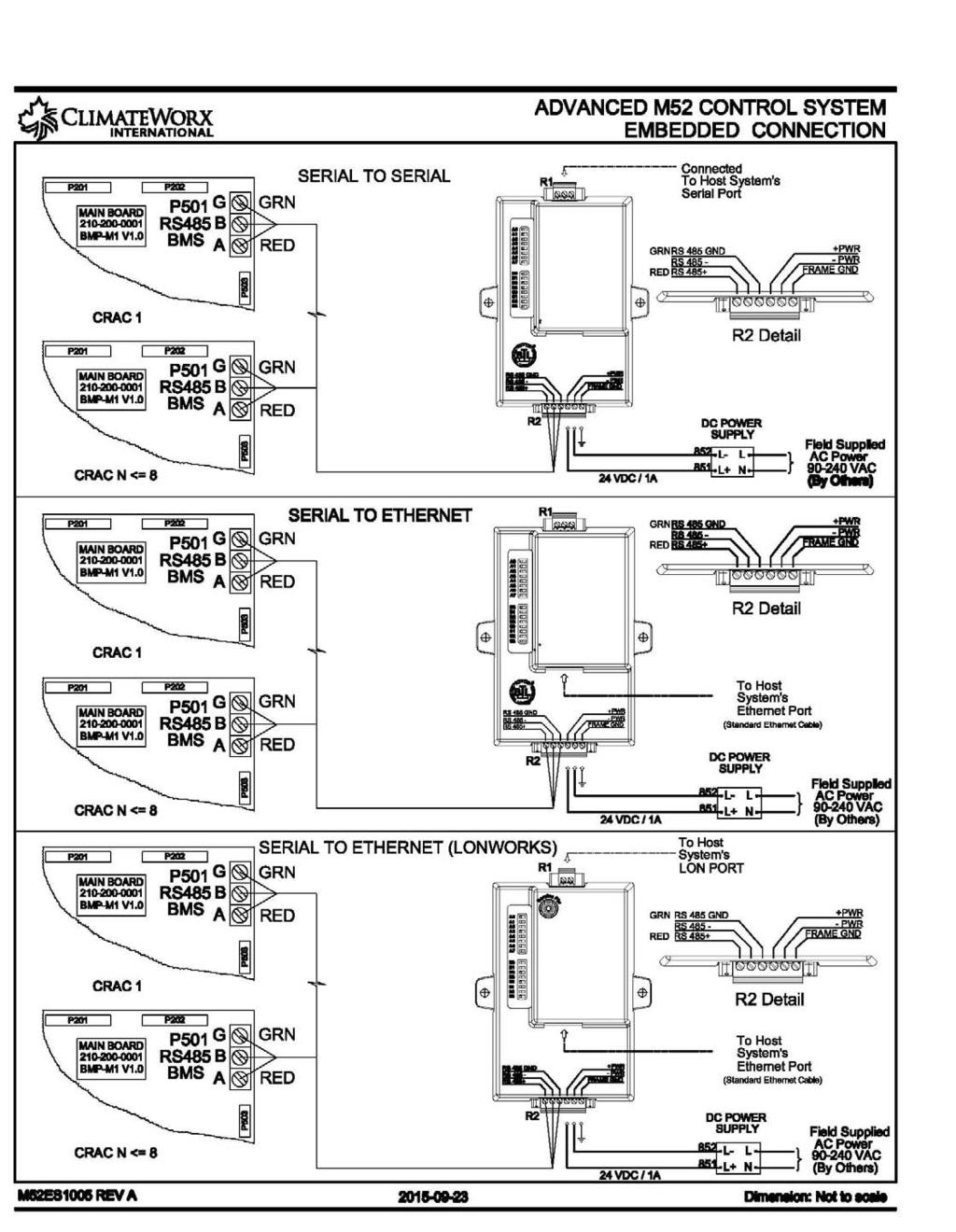
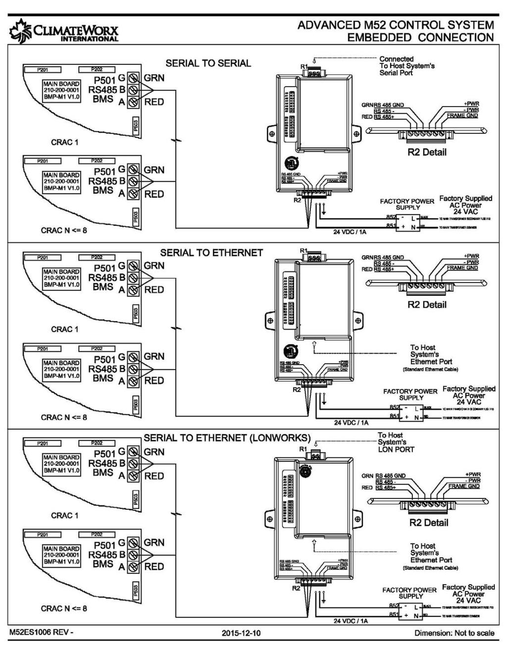
29 Appendix C: Electrical Schematic Diagrams Drawing Title Electric Schematic Packaged Air-Cooled General, Electric Schematic Air-Cooled General, Electric Schematic Water/ Glycol-Cooled General, Electric Schematic Chilled Water General, Electric Schematic Dual Cooling Air General, Electric Schematic Dual Cooling Water or Glycol General, Electric Schematic Free Cooling General, Electric Schematic Field Wiring Standby Start/ Standby Enable, For automatic change over Electric Schematic Co-Work I2C Interconnection Link Electric Schematic RS485 ModBus RTU Connection, Serial Communication Link Electric Schematic Embedded Connection, Serial to Serial or Ethernet Communication Link remote power Electric Schematic Embedded Connection, Serial to Serial or Ethernet Communication Link factory power Drawing No. ES9005 ES9030 ES9065 ES9050 ES9030 ES9040 ES9070 M52ES05 M52ES1003 M52ES1004 M52ES1005 M52ES
30 30
31 31
32 32
33 33
34 34
35 35
36 36
37 37
38 38
39 39
40 40
41 41
42 42
Series 6, Vertical Floor-Mount Units
 MISSION CRITICAL Air Conditioning Systems Series 6, Vertical Floor-Mount Units Installation Manual ClimateWorx International Inc. 14 Chelsea Lane, Brampton, Ontario, Canada L6T 3Y4 2 Table of Contents
12 In Row. Installation Manual. MISSION CRITICAL Air Conditioning Systems. ClimateWorx International Inc.
 MISSION CRITICAL Air Conditioning Systems 12 In Row Installation Manual ClimateWorx International Inc. 14 Chelsea Lane, Brampton, Ontario, Canada L6T 3Y4 2 Table of Contents Table of Contents... 3 Site
P-Series, Vertical Floor-Mount Units
 MISSION CRITICAL Air Conditioning Systems P-Series, Vertical Floor-Mount Units Installation Manual ClimateWorx International Inc. 14 Chelsea Lane, Brampton, Ontario, Canada L6T 3Y4 - 2 - SP-IM2018 Table
Series 11, Ceiling Units
 MISSION CRITICAL Air Conditioning Systems Series 11, Ceiling Units Installation Manual ClimateWorx International Inc. 14 Chelsea Lane, Brampton, Ontario, Canada L6T 3Y4 Table of Contents Table of Contents...
Series 11, Ceiling Units
 MISSION CRITICAL Air Conditioning Systems Series 11, Ceiling Units Installation Manual ClimateWorx International Inc. 14 Chelsea Lane, Brampton, Ontario, Canada L6T 3Y4 Table of Contents Table of Contents...
Condensing Unit Installation and Operating Instructions
 Bulletin WCU_O&I 01 June 2003 Condensing Unit Installation and Operating Instructions WCU Air Cooled Condensing Unit Table of Contents Section 1. Section 2. Section 3. Section 4. Section 5. Section 6.
CS/CD/CP AIR COOLED CONDENSING UNITS (P/N E207120C R2)
") CS*/CD*/CP* Series Air Cooled Condensing Units Operating and Installation Manual CS/CD/CP AIR COOLED CONDENSING UNITS (P/N E207120C R2) TABLE OF CONTENTS I. Receipt of Equipment 2 II. Piping...4 III. System
CS*/CD*/CP* Series Air Cooled Condensing Units Operating and Installation Manual CS/CD/CP AIR COOLED CONDENSING UNITS (P/N E207120C R2) TABLE OF CONTENTS I. Receipt of Equipment 2 II. Piping...4 III. System
Condensing Unit Installation and Operating Instructions
 Bulletin ACU_O&I 02 August 2016 Condensing Unit Installation and Operating Instructions ACU Air Cooled Condensers Table of Contents Section 1. General Information... 2 Section 2. Refrigeration Piping...
Service Step by Step Trouble-Shooting Check-List
 WARNING: Only Data Aire trained technician or experience technicians should be working on Data Aire Equipment. Protect yourself at all times and work safe. Date: Dates at the job site: From: to Job#: Serial#:
Series 9. Commissioning Checklist. MISSION CRITICAL Air Conditioning Systems. ClimateWorx International Inc.
 MISSION CRITICAL Air Conditioning Systems Series 9 Commissioning Checklist S9-CL2017.doc ClimateWorx International Inc. 14 Chelsea Lane, Brampton, Ontario, Canada L6T 3Y4 2 S9-CL2017.doc Commissioning
PARALLEL RACK SYSTEM INSTALLATION & OPERATIONS MANUAL With Master Rack Compressor Sequencer
 PARALLEL RACK SYSTEM INSTALLATION & OPERATIONS MANUAL With Master Rack Compressor Sequencer 5/16 Rev. A 57-02509 2 Contents INTRODUCTION... 4 WARNING LABELS AND SAFETY INSTRUCTIONS... 5 PS SERIES PARALLEL
APPLICATION DATA SHEET
 APPLICATION DATA SHEET General Piping Recommendations and Refrigerant Line Length for Split-System Air Conditioners and Heat Pumps GENERAL GUIDELINES This Split-System (Air Conditioning Condensing/Heat
TECHNICAL MANUAL CX(E) SPLIT SYSTEMS. Tel: Fax:
 SPLIT SYSTEMS. Tel: Fax:") TECHNICAL MANUAL CX(E) SPLIT SYSTEMS CONTENTS INDEX PART NUMBERS, OPTIONS, UNIT COMBINATIONS, DIMENSIONS & WEIGHTS 3 PERFORMANCE DATA & AIR FLOW 4 SOUND POWER AND SOUND PRESSURE LEVELS 5 ELECTRICAL DATA
TECHNICAL MANUAL CX(E) SPLIT SYSTEMS CONTENTS INDEX PART NUMBERS, OPTIONS, UNIT COMBINATIONS, DIMENSIONS & WEIGHTS 3 PERFORMANCE DATA & AIR FLOW 4 SOUND POWER AND SOUND PRESSURE LEVELS 5 ELECTRICAL DATA
Air Cooled Condenser Installation and Operating Instructions
 Bulletin CAC_O&I 02 August 2016 Air Cooled Condenser Installation and Operating Instructions CAC Air Cooled Condensers Table of Contents Section 1. General Information... 2 Section 2. Refrigeration Piping...
WKS 2200 SERIES (USA only) --INSTALLATION INSTRUCTIONS--
 --INSTALLATION INSTRUCTIONS--") 8610 Production Avenue San Diego, California 92121 (858) 566-7465 Fax (858) 566-1943 WWW.BREEZAIRE.COM WKS 2200 SERIES (USA only) --INSTALLATION INSTRUCTIONS-- Thank you for choosing a BREEZAIRE cooling
8610 Production Avenue San Diego, California 92121 (858) 566-7465 Fax (858) 566-1943 WWW.BREEZAIRE.COM WKS 2200 SERIES (USA only) --INSTALLATION INSTRUCTIONS-- Thank you for choosing a BREEZAIRE cooling
Series 6. Guide Specification 60 Hz. MISSION CRITICAL Air Conditioning Systems. ClimateWorx International Inc.
 MISSION CRITICAL Air Conditioning Systems Series 6 Guide Specification 60 Hz S6-GS-602017.doc ClimateWorx International Inc. 14 Chelsea Lane, Brampton, Ontario, Canada L6T 3Y4 Series 6 Guide Specification-60
Installation, Operation, and Maintenance Information
 Installation, Operation, and Maintenance Information Air Cooled Condensers 8-2016 Rev 0 Table of Contents General Safety Information 2 Inspection 2 Installation 2 6 Rigging and Assembly 2 Unit Location
Series 8. Guide Specification 60 Hz. MISSION CRITICAL Air Conditioning Systems. ClimateWorx International Inc.
 MISSION CRITICAL Air Conditioning Systems Series 8 Guide Specification 60 Hz S8-GS-602017.doc 2014 ClimateWorx International Inc. 14 Chelsea Lane, Brampton, Ontario, Canada L6T 3Y4 Series 8 Guide Specification-60
YCIV Hz & Hz
 YCIV 0590-1500 50Hz & 0157-0397 60Hz Start-up Checklist SERVICE POLICY & PROCEDURES Supersedes: Nothing Form 201.23-CL1 (309) Commissioning PREPARATION Commissioning of this unit should only be carried
Installation Instructions
 Installation Instructions B-Series VT40, VT60, VT100 Important Safety Notice. This information is intended for use by individuals possessing adequate backgrounds of electrical, refrigeration and mechanical
Contour TM Screw Compressors
 Contour TM Screw Compressors Semi-Hermetic Compact Operating Instruction SCH1 High Temp Compressors Form No. 99-77 1. Introduction This series of semi-hermetic compact screw compressors is designed for
June 2001 / BULLETIN Way Valves. The right solenoid valve for any job.
 June 01 / BULLETIN - 3-Way Valves The right solenoid valve for any job. Page 2 / Bulletin - Advantages Sporlan 3-Way Valves 3-Way Pilot eliminates costly high- to low-side leaks. "B" reduces total installed
Some of these procedures need to be performed to conform to requirements of the Clean Air Act.
 Leak Detection, Recovery, Evacuation and Charging Four basic service procedures used to repair and maintain a mechanical refrigeration system are leak detection, evacuation, recovery, and refrigerant charging.
Operation & Maintenance Manual
 Operation & Maintenance Manual VUD, VUF, VDF & HCD Series Unit Ventilator IMPORTANT: Read and save this manual for future reference. This manual is to be left with the equipment owner 2006 TEMSPEC INCORPORATED
Mission Critical. Series 6, 8 & 9. vertical floor mount Ton Units. Air Conditioning Systems
 Mission Critical Air Conditioning Systems vertical floor mount Series 6, 8 & 9 2-30 Ton Units Single Circuit for Superior Economy and Dual Circuit for Ultimate Protection Series 6 2-5 tons Compact Footprint
PDF Created with deskpdf PDF Writer - Trial ::
 Instruction Manual Index Introduction Uncrating and Checking for Damage Locating Your Unit Installation Fill Tank Process Connections Pre Startup Startup Sequence Trouble Shooting Chart Operating Lights
Table of Contents. Service Procedures. Service Procedures. Measuring Superheat (4) Measuring Subcooling (5) Airflow Calculation (6-8)
 Measuring Subcooling (5) Airflow Calculation (6-8)") Table of Contents Refrigeration Cycle Service Procedures Measuring Superheat (4) Measuring Subcooling (5) Airflow Calculation (6-8) Solving Problems Identifying Low System Charge (9-11) Identifying High
Table of Contents Refrigeration Cycle Service Procedures Measuring Superheat (4) Measuring Subcooling (5) Airflow Calculation (6-8) Solving Problems Identifying Low System Charge (9-11) Identifying High
AIR CONDITIONING. Carrier Corporation 2002 Cat. No
 AIR CONDITIONING Carrier Corporation 2002 Cat. No. 020-016 1. This refresher course covers topics contained in the AIR CONDITIONING specialty section of the North American Technician Excellence (NATE)
AMERICAN EQUIPMENT SYSTEMS A Division Of Trevor-Martin Corporation th Terrace North Clearwater, Florida 33762
 AMERICAN EQUIPMENT SYSTEMS A Division Of Trevor-Martin Corporation 4151 112 th Terrace North Clearwater, Florida 33762 COMMERCIAL REFRIGERANT DESUPERHEATER WASTE HEAT RECOVERY INSTALLATION/OPERATION/MAINTENANCE
DLCLRA. INSTALLATION INSTRUCTIONS Outdoor Unit Single Zone Ductless System Sizes 36 to 58 TABLE OF CONTENTS
 DLCLRA INSTALLATION INSTRUCTIONS Outdoor Unit Single Zone Ductless System Sizes 36 to 58 Fig. 1 - Size 36 TABLE OF CONTENTS PAGE SAFETY CONSIDERATIONS... 2 PARTS LIST... 3 SYSTEM REQUIREMENTS... 4 WIRING...
Ocean Breeze Split System. General Installation Manual. Ocean Breeze 2951 SE Dominica Terrace Stuart, Florida Tel:
 Ocean Breeze Split System General Installation Manual Ocean Breeze 2951 SE Dominica Terrace Stuart, Florida 34997 Tel: 772 220 0038 Warning: The Air Conditioning Unit is a pressurized system; potential
Air-Cooled Condenser. Installation Instructions. Revision Date: 12/21/98
 Air-Cooled Condenser Installation Instructions Revision Date: 12/21/98 ! WARNING! These installation guidelines must be followed to obtain reliable operation from air-cooled ice machines. If these guidelines
WineZone Ceiling Mount Ductless Split 15
 WineZone Ceiling Mount Ductless Split 15 Requires an HVAC technician to install and charge with R-22 refrigerant. Easy to install. Unit plugs into wall outlet. Industrial grade unit for longer life. Indoor
Installation Instructions
 8GXM / 0GXM Multi---Split High---Wall Duct Free Split System 8GXM --- Size 18k, k, and 0k 0GXM --- Size 9k, 1k, and 18k Installation Instructions NOTE: Read the entire instruction manual before starting
Series PS6, Vertical Floor-Mount Units
 Series PS6, Vertical Floor-Mount Units Technical Data 60 Hz sps6em6ea.doc Dec-12 ClimateWorx International Inc. 14 Chelsea Lane, Brampton, Ontario, Canada L6T 3Y4 Table of Contents Table of Contents...
TECHNICAL GUIDE DESCRIPTION SPLIT-SYSTEM AIR-COOLED CONDENSING UNITS. HA300, HB360, HB480 & HB thru 50 NOMINAL TONS (50 Hz)
") DESCRIPTION These units are completely assembled, piped and wired at the factory to provide one-piece shipment and rigging. Each unit is pressurized with a holding charge of refrigerant-22 for storage
DESCRIPTION These units are completely assembled, piped and wired at the factory to provide one-piece shipment and rigging. Each unit is pressurized with a holding charge of refrigerant-22 for storage
WKS 4000 SERIES (USA only) --INSTALLATION INSTRUCTIONS--
 --INSTALLATION INSTRUCTIONS--") 8610 Production Avenue San Diego, California 92121 (858) 566-7465 Fax (858) 566-1943 WKS 4000 SERIES (USA only) --INSTALLATION INSTRUCTIONS-- Thank you for choosing a BREEZAIRE cooling unit. We believe
8610 Production Avenue San Diego, California 92121 (858) 566-7465 Fax (858) 566-1943 WKS 4000 SERIES (USA only) --INSTALLATION INSTRUCTIONS-- Thank you for choosing a BREEZAIRE cooling unit. We believe
Liebert CSU3000 Chiller
 CSI 15620 - Packaged Water Chillers Liebert CSU3000 Chiller Guide Specifications for 7.5-37 Ton CS/CD/CT Models 1.0 GENERAL 1.1 CS/CD MODELS The main-frame coolant supply unit shall be a Liebert Model,
Installation Instructions
 PREFERREDT SERIES AIR CONDITIONER WITH PURONR REFRIGERANT 1-1/2 TO 5 NOMINAL TONS Installation Instructions Fig. 1 --- 538A NOTE: Read the entire instruction manual before starting the installation. TABLE
TABLE OF CONTENTS. NOTE: Read the entire instruction manual before starting the installation. TROUBLESHOOTING... 13
 R 410A Duct Free Split System Air Conditioner and Heat Pump Product Family: DFS4(A/H) System, DFC4(A/H)3 Outdoor, DFF4(A/H)H Indoor NOTE: Read the entire instruction manual before starting the installation.
Installation Instructions
 24AHA4 Performance Series Air Conditioner with Puron Refrigerant 1-1/2 to 5 Nominal Tons Installation Instructions Fig. 1-24AHA4 A07532 SAFETY CONSIDERATIONS Improper installation, adjustment, alteration,
Instructors: Contact information. Don Reynolds Doug McGee Factory Tech Support
 Contact information Instructors: Don Reynolds 616-560-9903 Doug McGee 517-294-3932 Factory Tech Support 888-593-9988 Product Improvements for 2017 Todays Objectives Job Site Information Sheets Low Ambient
Daikin Direct Expansion (DX) Cooling Coils
 Cooling Coils") Installation and Maintenance Manual IM 902 Daikin Direct Expansion (DX) Cooling Coils Group: Applied Air Part Number: IM 902 Date: February 2008 Types EN, EF, ER, EJ, EK 2008 Daikin Applied Contents Introduction...
Installation and Maintenance Manual IM 902 Daikin Direct Expansion (DX) Cooling Coils Group: Applied Air Part Number: IM 902 Date: February 2008 Types EN, EF, ER, EJ, EK 2008 Daikin Applied Contents Introduction...
TRI-PLATE B INSTALLATION, OPERATION, AND MAINTENANCE INSTRUCTIONS PART NO EFFECTIVE MARCH 1, 1983 REPRINT APRIL 16, 1999
 TRI-PLATE B INSTALLATION, OPERATION, AND MAINTENANCE INSTRUCTIONS PART NO. 8801469 EFFECTIVE MARCH 1, 1983 REPRINT APRIL 16, 1999 THE MILK COOLING SYSTEMS SPECIALISTS TM FRE-HEATER Part No. 8801469 Table
RCM Refrigerant Module
 Small Duct High Velocity Heating, Cooling and Home Comfort Systems RCM Refrigerant Module Installation Manual Manufactured By Module-RCM-Refrigerant-Module-Installation-0666 Refrigerant Modules (RCM) Fig.
Assessment Schedule - TS8
 The Assessor shall determine the business s commitment and support to good and safe working practices; also that it has a positive culture in all aspects of its work. In particular, the assessor shall
Chapter-8 Capacity Control of Refrigeration Systems
 Chapter-8 Capacity Control of Refrigeration Systems Chapter-8 Capacity Control of Refrigeration Systems ၈.၁ Compressor Control Chiller Control and Chilled Water Plant Control Refrigeration system control
Calhoon MEBA Engineering School. Study Guide for Proficiency Testing Refrigeration
 Calhoon MEBA Engineering School Study Guide for Proficiency Testing Refrigeration 1. To prevent an injury when working with refrigerants, what safety precautions are necessary? 2. When halogens are in
R Series Cooling Modules
 TM Small Duct High Velocity Heating, Cooling and Indoor Air Quality Systems R Series Cooling Modules Models RCM-50 RCM-70 RM-100 Manufactured By Module-RCM/RM-Series-Installation-Manual-120113 Refrigerant
INSTALLATION INSTRUCTIONS
 INSTALLATION INSTRUCTIONS SPLIT AIR CONDITIONER OUTDOOR SECTION Models: HAC481-B HAC602-B For Use With: Matching Indoor Blower Coil Units and Matching Add On Coil Units Only Bard Manufacturing Company,
EQUIPMENT PRE-STARTUP AND STARTUP CHECKLIST TEL NO: ORDER NO: CONTRACT NO:
 Supersedes: (316) Form QTC4-CL2 (617) MODEL QTC4 EQUIPMENT PRE-STARTUP AND STARTUP CHECKLIST CUSTOMER: ADDRESS: PHONE: JOB NAME: LOCATION: CUSTOMER ORDER NO: TEL NO: ORDER NO: CONTRACT NO: CHILLER MODEL
Microchannel REMOTE AIR COOLED CONDENSER. Technical Bulletin: MXCC_004_ Products that provide lasting solutions.
 Microchannel REMOTE AIR COOLED CONDENSER Technical Bulletin: MXCC_004_030817 Products that provide lasting solutions. Krack s new Microchannel Remote Air Cooled Condenser incorporates a new patented modular
SECTION 5 COMMERCIAL REFRIGERATION UNIT 22 CONDENSERS UNIT OBJECTIVES UNIT OBJECTIVES 3/22/2012
 SECTION 5 COMMERCIAL REFRIGERATION UNIT 22 CONDENSERS UNIT OBJECTIVES After studying this unit, the reader should be able to explain the purpose of the condenser in a refrigeration system. describe differences
R Series Cooling Modules
 R Series Cooling Modules Models RCM/RPM 50 RCM 70 RM 100 RM 140 Manufactured By Energy Saving Products Ltd. Standard ESP 105.03 Refrigerant Modules (RCM/RM) Fig. 02 - Mounting brackets The cooling coil
Installation, Start-Up and Service Instructions
 38AH044-134 Air-Cooled Condensing Units 50/60 Hz Installation, Start-Up and Service Instructions CONTENTS Page SAFETY CONSIDERATIONS...................... 1 INSTALLATION................................
Split Floor-Mounted Cooling System Operation Care Installation Manual
 Split Floor-Mounted Cooling System Operation Care Installation Manual CT14TSA CT13TSA CT12TSA CT34TSA CT1TSA CT14TSA-LA CT13TSA-LA CT12TSA-LA CT34TSA-LA CT1TSA-LA www.apexwinecellars.com Apex 17631 S Susana
WMHP Series R410a Heat Pump INSTALLATION INSTRUCTIONS
 WMHP Series R410a Heat Pump INSTALLATION INSTRUCTIONS **WARNING TO INSTALLER, SERVICE PERSONNEL AND OWNER** Altering the product or replacing parts with non authorized factory parts voids all warranty
.2 Section Waste Management and Disposal.
 Issued 2005/06/01 Section 15624 Packaged Rotary Screw Water Chillers Page 1 of 5 PART 1 General 1.1 RELATED SECTIONS.1 Section 01330 Submittal Procedures..2 Section 01355 Waste Management and Disposal..3
MODEL YVAA EQUIPMENT PRE-STARTUP AND STARTUP CHECKLIST CUSTOMER: LOCATION: ADDRESS: CUSTOMER ORDER NO: PHONE: JCI CONTRACT NO: JOB NAME:
 Supersedes: 201.28-CL2 (817) Form 201.28-CL2 (1017) MODEL YVAA EQUIPMENT PRE-STARTUP AND STARTUP CHECKLIST CUSTOMER: LOCATION: ADDRESS: PHONE: JOB NAME: CUSTOMER ORDER NO: JCI CONTRACT NO: CHILLER MODEL
Read and save these instructions
 Split Water-Cooled Central-Ducted Cooling System Operation Care Installation Manual CT14TSHWC CT13TSHWC CT12TSHWC CT34TSHWC CT1TSHWC www.apexwinecellars.com 17631 S Susana Road Rancho Dominguez, CA 90221
INSTALLATION AND OPERATING INSTRUCTIONS
 INSTALLATION AND OPERATING INSTRUCTIONS HIGH-EFFICIENCY CONDENSING UNITS RAWD- 6 1 2 & 7 1 2 TON RAWE - 6 1 2 & 7 1 2 TON! RECOGNIZE THIS SYMBOL AS AN INDICATION OF IMPORTANT SAFETY INFORMATION!! WARNING
Installation Instructions
 38MHR Outdoor Unit Single Zone Ductless System Sizes 09 to 24 Installation Instructions NOTE: Read the entire instruction manual before starting the installation. NOTE: Images are for illustration purposes
Installation Manual BCS2000/3000
 Installation Manual BCS2000/3000 Supplies Needed for Installation 1. 3/8 and 5/8 copper tubing. 2. 1/4 copper water supply 3. 1/4 condensate vinyl drain tube/tube clamps 4. Provide 120v 15A circuit for
PACKAGED AIR COOLED Product Data Catalog
 PACKAGED AIR COOLED Product Data Catalog MODELS ASP-10A ASP-15A ASP-20A ASP-00P ASP-00F ASP-00G A MEMBER OF MARDUK HOLDING COMPANY, LLC The Leader in Modular Chillers ETL and CSA Approved CHILLER MODULES
Eclipse Technical Training CME686 CME810 CP686 CP886 CP1086
 Eclipse Technical Training CME686 CME810 CP686 CP886 CP1086 In This Presentation What Eclipse is Components and their functions Installation Operation Maintenance Service Diagnosis The Eclipse System The
Installation Instructions. Revision Date: 05/16/12
 Air-Cooled Condenser Installation Instructions Revision Date: 05/16/12 ! WARNING! These installation guidelines must be followed to obtain reliable operation from air-cooled ice machines. If these guidelines
Accumulators - Suction Line
 ACCUMULATORS Accumulators - Suction Line kw Cap at Evap. Temp. -6 C Size Connection R22 R404A / R507C F0804 1/2" ODS Vertical 4.6 4.8 F0805 5/8" ODS Vertical 6.9 7.2 F0806 3/4" ODS Vertical 9.2 9.6 F0807
Residential Piping and Long Line Guideline
 AC / HP R-410A Refrigerant Systems Single-Stage, Two-Stage and Variable Speed Models Residential Piping and Long Line Guideline TABLE OF CONTENTS Safety Considerations... 2 Definitions... 2 Introduction...
SECTION REFRIGERATION EQUIPMENT. A. Section Includes: Refrigeration equipment for insulated cold storage rooms including necessary accessories.
 SECTION 15650 REFRIGERATION EQUIPMENT PART 1 GENERAL 1.01 SUMMARY A. Section Includes: Refrigeration equipment for insulated cold storage rooms including necessary accessories. B. Related Section: 1. 11400
SECTION AIR COILS
 PART 1 - GENERAL 1.1 RELATED DOCUMENTS A. Drawings and general provisions of the Contract, including General and Supplementary Conditions and Specification Sections, apply to this Section. B. Related Sections:
Air Conditioning Clinic. Refrigerant Piping One of the Fundamental Series TRG-TRC006-EN
 Air Conditioning Clinic Refrigerant Piping One of the Fundamental Series TRG-TRC006-EN NO POSTAGE NECESSARY IF MAILED IN THE UNITED STATES BUSINESS REPLY MAIL FIRST-CLASS MAIL PERMIT NO. 11 LA CROSSE,
Single Package Vertical Unit (SPVU) Installation, Operation and Maintenance Manual Effective August 2018
 Installation, Operation and Maintenance Manual Effective August 2018") VertiCool CLASSIC Single Package Vertical Unit (SPVU) Installation, Operation and Maintenance Manual Effective August 2018 Air-Cooled, Water-Cooled, Chilled Water and Water Source Heat Pump Contents Installation,
VertiCool CLASSIC Single Package Vertical Unit (SPVU) Installation, Operation and Maintenance Manual Effective August 2018 Air-Cooled, Water-Cooled, Chilled Water and Water Source Heat Pump Contents Installation,
DUNHAM-BUSH. Request for start-up and commissioning of Dunham-Bush chillers (Water Cooled or Air Cooled) and Condensing Units.
 and Condensing Units.") DUNHAM-BUSH Request for start-up and commissioning of Dunham-Bush chillers (Water Cooled or Air Cooled) and Condensing Units. Job Name Unit Model Address & Location Unit Serial Number of Units Kindly complete,
DUNHAM-BUSH Request for start-up and commissioning of Dunham-Bush chillers (Water Cooled or Air Cooled) and Condensing Units. Job Name Unit Model Address & Location Unit Serial Number of Units Kindly complete,
Installation 50% Service 20% Components 20% Applied Knowledge 10%
 LIGHT COMMERCIAL REFRIGERATION INSTALLATION CERTIFICATION Certification Information Scope - Tests a candidate's knowledge of the installation, service, maintenance, and repair of Light Commercial Refrigeration
MAC-120HE-03 Air-Cooled Chiller
 MAC-120HE-03 Air-Cooled Chiller 10 Ton / 120,000 BTUH Air-Cooled Chiller 380/415/460-3-50/60 1 HVAC Guide Specifications Air-Cooled Liquid Chiller Nominal Size: 10 Tons Multiaqua Model Number: MAC-120HE-03
Energy Use in Refrigeration Systems
 2012 Rocky Mountain ASHRAE Technical Conference Energy Use in Refrigeration Systems PRESENTED BY: Scott Martin, PE, LEED AP BD+C Objectives Understand mechanical refrigeration terms Describe how heat is
CNC Series Refrigerated Air Dryer CFM
 CNC Series Refrigerated Air Dryer 10 3000 CFM NEW Engineered to Save CNC Value CompAir leads the way in providing value to our customers We looked beyond the typical refrigerated air dryer and designed
Thomas J Kelly. Fundamentals of Refrigeration. Sr. Engineering Instructor Carrier Corporation. August 20, Page number: 1.
 Thomas J Kelly Sr. Engineering Instructor Carrier Corporation August 20, 2003 1 SESSION OBJECTIVES At the conclusion of this session you should be able to: 1. Describe the basics principles of refrigeration
FULLY SELF-CONTAINED AIR CONDITIONING WITH INDUSTRIAL DURABILITY
 C A P A C I T Y R U G G E D, I N D O O R/ R E A D Y T O T O T A L L O C A L M A T C H E D O U T D O O R D E S I G N I N S T A L L S U P P O R T E N V I R O N M E N T A L C O N T R O L Liebert Industrial
NOTE: Special care should be given to those areas where these symbols appear.
 CONGRATULATIONS ON THE SELECTION OF A DATA AIRE PRECISION ENVIRONMENTAL CONTROL SYSTEM. PROPER INSTALLATION, OPERATION AND MAINTENANCE OF THIS EQUIPMENT WILL ENSURE YEARS OF OPTIMAL PERFORMANCE. There
RSES Technical Institute Training Manual 2 72 hours, 72 NATE CEHs, 7.2 CEUs
 Lesson 1 - Trade Tools Explain the importance of using proper tools and test instruments. List the various types of wrenches and describe their use. Describe the proper procedures for bending, flaring,
REFRIGERANT PIPING
 SECTION 232300 - REFRIGERANT PIPING PART 1 - GENERAL 1.1 RELATED DOCUMENTS A. Drawings and general provisions of the Contract, including General and Supplementary Conditions and Division 01 Specification
Mortex INSTALLATION INSTRUCTIONS AIR CONDITIONING & HEAT PUMP INDOOR COILS
 Mortex INSTALLATION INSTRUCTIONS AIR CONDITIONING & HEAT PUMP INDOOR COILS INTRODUCTION Please note that HUD Manufactured Home Construction and Safety Standard Section 3280.714, paragraph (a) and subparagraph
B. Unit construction shall comply with ASHRAE 15 Safety Code, NEC, and ASME applicable codes (U.S.A. codes).
.") Guide Specifications PART 1 GENERAL 1.01 SYSTEM DESCRIPTION Microprocessor controlled, air-cooled liquid chiller utilizing scroll compressors, low sound fans, hydronic pump system and optional fluid storage
Guide Specifications PART 1 GENERAL 1.01 SYSTEM DESCRIPTION Microprocessor controlled, air-cooled liquid chiller utilizing scroll compressors, low sound fans, hydronic pump system and optional fluid storage
DESIGN STANDARDS SECTION 15600
 PART 1 - GENERAL 1.1 Work included: A. Piping, tubing and fittings. B. Piping specialties. C. Special duty valves. D. Refrigerants. E. Chillers. F. Refrigerant monitors. 1.2 General requirements: A. Reciprocating
COMPU KOOL III -INSTALLATION AND OPERATION MANUAL-
 COMPU KOOL III -INSTALLATION AND OPERATION MANUAL- 8167 Byron Road Whittier, CA 90606 Phone: (562) 945-8971 Fax: (562) 696-0724 www.compu-aire.com 1 AIR COOLED (CKA) WATER COOLED (CKW) GLYCOL COOLED (CKG)
REFRIGERATION AND AIR CONDITIONING RÉFRIGÉRATION ET CLIMATISATION POST-SECONDARY NIVEAU POSTSECONDAIRE
 INSTRUCTIONS AND COMPETITION DETAILS INSTRUCTIONS ET DÉTAILS DU CONCOURS REFRIGERATION AND AIR CONDITIONING RÉFRIGÉRATION ET CLIMATISATION POST-SECONDARY NIVEAU POSTSECONDAIRE 1. Test Project Details This
EarthLinked SW Series Compressor Unit R-410A Quik-Start Instructions
 EarthLinked SW Series Compressor Unit R-410A Quik-Start Instructions CONTENTS PAGE Pre-Installation 3 Placement & Mechanical Information 4 System Application Options 10 Antifreeze Protection 14 Electrical
TECHNICAL GUIDE DESCRIPTION SPLIT-SYSTEM AIR-COOLED CONDENSING UNITS MODELS: HF-07 FEATURES B-0703
 TECHNICAL GUIDE SPLIT-SYSTEM AIR-COOLED CONDENSING UNITS MODELS: HF-07 DESCRIPTION These Sunline 2000 units are completely assembled, piped and wired at the factory to provide one-piece shipment and rigging.
KITS COMMON TO HEATING AND COOLING EQUIPMENT 504,652M 03/04. Supersedes 503,249M
 2004 Lennox Industries Inc. Dallas, Texas KITS COMMON TO HEATING AND COOLING EQUIPMENT 504,652M 03/04 Supersedes 503,249M Litho U.S.A. COMPRESSOR REPLACEMENT KIT INSTALLATION INSTRUCTIONS FOR COMPRESSOR
INSTRUCTIONS! DO NOT DISCARD!
 INSTRUCTIONS! DO NOT DISCARD! CAUTION! Do NOT install where injury might occur due to Moving parts, Sharp corners, Hot surfaces or electrical components d N0417 Page 1 of 10 INSTALLATION INSTRUCTIONS CAUTION
INSTALLATION INSTRUCTIONS HOT GAS BYPASS SYSTEM DESIGN MANUAL
 INSTALLATION INSTRUCTIONS HOT GAS BYPASS SYSTEM DESIGN MANUAL MODELS: WA242H WA36H NOTE: Electrical data presented in this manualsupersedes any other data for the above listed models. Bard Manufacturing
TECHNICAL GUIDE. Description SPLIT-SYSTEM AIR-COOLED CONDENSING UNITS YD360, 480 & THRU 50 NOMINAL TONS YTG-B-0811
 Description These units are completely assembled, piped and wired at the factory to provide one-piece shipment and rigging. Each unit is pressurized with a holding charge of Refrigerant R-410A for storage
INSTALLATION MANUAL SPLIT-SYSTEM CONDENSING UNITS (AIR COOLED) HB Ton HB Ton HB Ton NOTES, CAUTIONS AND WARNINGS
 HB Ton HB Ton HB Ton NOTES, CAUTIONS AND WARNINGS") INSTALLATION MANUAL SPLIT-SYSTEM CONDENSING UNITS (AIR COOLED) CONTENTS GENERAL................................... 5 SAFETY CONSIDERATIONS.................... 5 AGENCY APPROVALS.........................
INSTALLATION MANUAL SPLIT-SYSTEM CONDENSING UNITS (AIR COOLED) CONTENTS GENERAL................................... 5 SAFETY CONSIDERATIONS.................... 5 AGENCY APPROVALS.........................
Best Practices for DX Piping. Greg Drensky Jacco & Associates
 Best Practices for DX Piping Greg Drensky Jacco & Associates Who is Jacco Established 1968 Hudson, Ohio Columbus, Ohio Toledo, Ohio Focused on the Engineered Environment Systems Knowledgeable HVAC Systems
Greenheck Coils A Complete Line of Custom Coils to Meet Your Needs. 3/8, 1/2 and 5/8 inch OD Tubing
 Greenheck Coils A Complete Line of Custom Coils to Meet Your Needs 3/8, 1/2 and 5/8 inch OD Tubing April 2012 Custom Coils Custom Coils Configured to Meet Your Needs Greenheck is proud to offer a complete
MAC N-407 Air-Cooled Chiller
 MAC036-01-N-407 Air-Cooled Chiller Air-Cooled Chillers for Global Residential and Light Commercial MicroClimates MAC036 NOMENCLATURE BREAKDOWN MAC036-01 - N - 407 Refrigerant Type Air-Cooled Chiller 036=
Guide Specifications for InRow Direct Expansion
 Guide Specifications Guide Specifications for InRow Direct Expansion THIS GUIDE SPECIFICATION IS WRITTEN IN ACCORDANCE WITH THE CONSTRUCTION SPECIFICATIONS INSTITUTE (CSI) MASTERFORMAT. THIS SECTION MUST
R Series Cooling Manual
 Mini Duct Heating and Air Conditioning Indoor Air Quality Systems R Series Cooling Manual Includes: RPM-E-50 Cooling Module RPM-E-0 Cooling Module RPM-E-00 Cooling Module Manufactured By Energy Saving
This chapter is devided into two sections:
 This chapter is devided into two sections: Page Installation requirements........................................................................ 127 The installation process..........................................................................