Tornado Operations & Maintenance Manual
|
|
|
- Allen Rogers
- 6 years ago
- Views:
Transcription
 867-5100 FAX (708)")

1 TORNADO INDUSTRIES 7401 W. LAWRENCE AVENUE CHICAGO, IL (708) FAX (708) Tornado Operations & Maintenance Manual MODEL NO BD26/30 & BD33/30 L9718AB 2014 Tornado Industries All rights reserved.
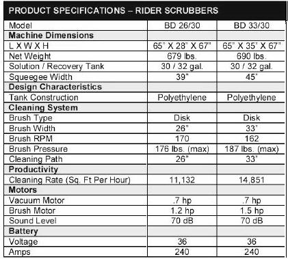
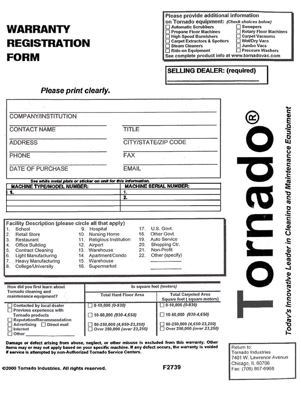
2 TABLE OF CONTENTS WARRANTY 2 PRODUCT SPECIFICATION 3 LEGEND: PANEL OF CONTROLS 4 LEGEND: MACHINE 4 INTRODUCTORY COMMENT 5 GENERAL RULES 5 SYMBOLS 5 BEFORE USE 6 Handling the packed machine 6 Unpacking the machine 6 Access to the battery compartment 6 Battery installation and setting the battery type 6 Assembling the rollbar 6 Battery recharger 6 Battery recharging 6 Battery disposal 7 Connection battery connector and switching on the machine 7 Battery charge level indicator 7 Hour meter 7 Squeegee assembly 7 Squeegee adjustment 7 Splash guard assembly 7 Brush assembly 8 FLOOR CLEANING 8 Recovery tank 8 Detergent solution tank 8 STARTING THE MACHINE 8 Horn 9 Brake 9 Emergency and parking brake 9 Automatic squeegee lift when going backwards 9 Working in automatic mode 9 Working in manual mode 9 Working adjustments 10 Flow adjustment of detergent solution 10 Brush pressure adjustment 10 Electric protection 10 Overflow device 10 STOPPING THE MACHINE AFTER CLEANING OPERATION 10 DAILY MAINTENANCE 10 Recovery tank emptying and cleaning 10 Suction filter cleaning 111 Brush cleaning 111 Brush disassembly 111 Squeegee cleaning 111 WEEKLY MAINTENANCE 111 Rear squeegee rubber check 11 Squeegee hose cleaning 111 Cleaning the solution tank and the outer filter 111 TWO-MONTH MAINTENANCE 111 Front squeegee rubber check 11 SIX-MONTH MAINTENANCE 111 Splash guard rubber check 111 Cleaning the inner filter solution tank 111 Checking the brake 111 TROUBLESHOOTING GUIDE 122 The vacuum motor does not work 122 The brush motor does not work 122 The traction motor does not work 122 The water does not come down onto the brush or is insufficient 122 The machine does not clean properly 122 The squeegee does not dry properly 122 Excessive foam production 122 PROGRAMMED MAINTENANCE 133 1
3 2
4 3
 10. PUSH BUTTON: VISUALIZATION BRUSH PRESSURE SET (DISPLAY) 11.")
 17. SIGNAL LAMP: STARTING BRUSH ROTATION 18. KEY SWITCH 19. PUSH BUTTON HORN 20. KNOB FOR SOLUTION VALVE LEGEND: MACHINE 1. RECOVERY TANK 2. SOLUTION TANK 3.")
5 LEGEND: PANEL OF CONTROLS 1. DISPLAY 2. SIGNAL LAMP: PARKING BRAKE 3. SELECTOR: AUTOMATIC/MANUAL 4. PUSH BUTTON: UP/DOWN SQUEEGEE 5. VACUUM MOTOR SWITCH 6. SIGNAL LAMP: UP/DOWN SQUEEGEE 7. SIGNAL LAMP: VACUUM MOTOR ON 8. BRUSH PRESSURE ADJUSTMENT KNOB 9. PUSH BUTTON: VISUALIZATION HOUR METER (DISPLAY) 10. PUSH BUTTON: VISUALIZATION BRUSH PRESSURE SET (DISPLAY) 11. SELECTOR: FORWARDS/BACKWARDS 12. SELECTOR: SPEED 13. PUSH BUTTON: UP/DOWN BRUSH 14. WATER OPENING SWITCH (SOLENOID VALVE) 15. SIGNAL LAMP: UP/DOWN BRUSH 16. SIGNAL LAMP: WATER OPEN (SOLENOID VALVE) 17. SIGNAL LAMP: STARTING BRUSH ROTATION 18. KEY SWITCH 19. PUSH BUTTON HORN 20. KNOB FOR SOLUTION VALVE LEGEND: MACHINE 1. RECOVERY TANK 2. SOLUTION TANK 3. SEAT 4. DRIVE WHEEL 5. SCREW CAP FOR INLET DETERGENT SOLUTION 6. BLINKING LIGHT 7. ROLLBAR 8. SUCTION HOSE 9. SUCTION COVER 10. SQUEEGEE HOSE 11. SUCTION COVER BLOCKING LEVERS 12. RECOVERY TANK EXHAUST HOSE PLUG 13. RECOVERY TANK EXHAUST HOSE 14. SQUEEGEE ASSEMBLY 15. PANEL CONTROLS 16. BLOCK/RELEASE PARKING BRAKE LEVER 17. ELECTRICAL LAYOUT COVER 18. BRAKE PEDAL 19. BUMPER 20. PEDAL ACCELERATOR 21. OUTER FILTER DETERGENT SOLUTION 22. STEERING WHEEL 23. BOTTOM PLATE 24. BRUSH BASE GROUP 25. TRACTION WHEELS 4


6 LEGEND PANEL OF CONTROLS 21. DISPLAY 22. SIGNAL LAMP MANUAL MODE ON 23. PUSH BUTTON CONNECTION MANUAL MODE 24. SIGNAL LAMP MODE BREAK WASHING ON 25. PUSH BUTTON CONNECTION MODE BREAK WASHING 26. PUSH BUTTON CONNECTION MODE AUTOMATIC 27. SIGNAL LAMP AUTOMATIC MODE ON 28. SIGNAL LAMP SUCTION MOTOR ON 29. SWITCH SUCTION MOTOR 30. ADJUSTMENT KNOB BRUSHES PRESSURE 31. PUSH BUTTON UP/DOWN SQUEEGEE 32. SIGNAL LAMP UP/DOWN SQUEEGEE 33. PUSH BUTTON VISUALIZATION HOUR METER (DISPLAY) 34. PUSH BUTTON VISUALIZATION BRUSHES PRESSURE SET (DIS- PLAY) 35. SIGNAL LAMP PARKING BRAKE ON 36. SIGNAL LAMP UP/DOWN BRUSHES 37. PUSH BUTTON UP/DOWN BRUSHES 38. SIGNAL LAMP STARTING BRUSHES ROTATION 39. PUSH BUTTON WATER OPENING (SOLENOID VALVE) or PUSH BUTTON ADJUSTMENT DETERGENT DOSAGE 3SD system (OP- TIONAL) 40. SIGNAL LAMP WATER OPEN (SOLENOID VALVE) 41. PUSH BUTTON FOR SPEED SELECTION 42. SIGNAL LAMP SELECTION MAXIMUM SPEED 43. SIGNAL LAMP SELECTION SLOW SPEED 44. KEY SWITCH MACHINE ON 45. SWITCH FOR FRONT LIGHT (OPTIONAL) 46. PUSH BUTTON HORN 47. KNOB FOR SOLUTION VALVE 48. SELECTOR DIRECTION OF DRIVE LEGEND MACHINE 26. RECOVERY TANK 27. SOLUTION TANK 28. SEAT 29. DRIVE WHEEL 30. SCREW CAP FOR INLET DETERGENT SOLUTION 31. BLINKING LIGHT 32. ROLLBAR 33. SUCTION HOSE 34. SUCTION COVER 35. SQUEEGEE HOSE 36. BLOCKING LEVERS SUCTION COVER 37. PLUG EXHAUST HOSE RECOVERY TANK 38. EXHAUST HOSE RECOVERY TANK 39. SQUEEGEE ASSEMBLY 40. PANEL CONTROLS 41. LEVER BLOCK/RELEASE PARKING BRAKE 42. COVER ELECTRICAL LAYOUT 43. BRAKE PEDAL 44. BUMPER 45. PEDAL ACCELERATOR 46. OUTER FILTER DETERGENT SOLUTION 47. STEERING WHEEL 48. BOTTOM PLATE 49. BRUSHES BASE GROUP 50. TRACTION WHEELS 5

7 INTRODUCTORY COMMENT Thank you for choosing our machine. This floor-cleaning machine is used for industrial and commercial cleaning and is able to clean any type of floor. During its forward movement, the action of the brush and detergent solution removes the dirt, which is picked up by the suction system, resulting in a dry surface. The machine must be used only for this purpose. It gives the best performance if it is used correctly and properly. Therefore, we ask you to read this instruction booklet carefully whenever difficulties arise in the course of the machine s use. If needed, please contact our service department for advice and/or service. GENERAL RULES The rules below have to be followed carefully in order to avoid damage to the machine and injuries to the operator. - Read the labels carefully on the machine. Do not cover them for any reason and replace them immediately if damaged. - The machine must be used exclusively by authorized staff that has been instructed for its use. - When using the machine, pay attention to other people, especially children. - In case of danger, immediately use the emergency brake. - To park the machine, take off the key and put on the parking brake. - Do not mix different detergents to avoid harmful odors. - Do not place any liquid containers onto the machine. - The storage temperature has to be between - 13 F and +131 F. - The operating temperature should be between 32 F and 104 F. - The humidity should be between 30 and 95%. - Do not use the machine in an explosive atmosphere. - Do not use the machine as a means of transportation. - Do not use acidic solutions, which could damage the machine and/or injure people. - Do not use the machine on surfaces covered with inflammable liquids or dusts (for example hydrocarbons, ashes or soot). - In case of fire, use a powder fire-extinguisher. Do not use water. - Watch out for shelves and/or scaffoldings, when operating the machine. - Use the appropriate speed based on floor conditions (type of floor, dirtiness, etc). - Do not use the machine on areas that have a higher gradient than the one stated on the number plate. - The machine has to carry out simultaneously the operations of washing and drying. Different operations must be carried out in restricted areas prohibited to non-authorized personnel. - Signal the areas of moist floors with suitable signs. - If the machine does not work properly, check by conducting simple maintenance procedures. Otherwise, contact an authorized technical assistant for advice. - Where parts are required, ask for ORIGINAL spare parts to the distributor or an authorized dealer. - Use only ORIGINAL brushes. - When cleaning and performing maintenance operations, disconnect the power supply plug from the machine. - Do not wash the machine with corrosive material, direct water jets or high water pressure. - Every 200 working hours, have the machine checked by an authorized service center. - In order to avoid scales on the solution tank filter, do not fill the detergent solution hours before it is used. - Before using the machine, check that all panels and coverings are in position as indicated in this use and maintenance catalog. - Be sure the recovery tank is empty before lifting it. - Restore all electrical connections after any maintenance operation. - When your machine has to stop activity, provide the appropriate waste disposal for its materials, especially oils, battery and electronic components. Consider that the machine itself has been constructed by recyclable materials. SYMBOLS Symbol denoting the switch for the water opening and the signal lamp that the water is open. Symbol denoting the function of the solution valve adjusting the flow of the detergent solution. Indication of the maximum temperature of the detergent solution. It is placed near the charging hole of the solution tank. Symbol denoting the selection switch of the operation mode manual/automatic. Symbol denoting the push button and the signal lamp up/down brush. Symbol denoting the signal lamp starting the brush rotation. Symbol denoting the push button to visualize on the display the brush pressure set. Symbol denoting the functioning of the adjustment knob of brush pressure. Symbol denoting the push button and the signal lamp up/down of the squeegee. 5 Symbol denoting the switch of the vacuum motor. Symbol denoting the charge level of the battery. Symbol denoting the push button to visualize the hour meter on the display. Symbol denoting the drive selector forwards/backwards. Symbol denoting the selection switch of the operation speed. Symbol denoting the signal lamp of the parking brake switched on. Symbol denoting the lever position for the connection of the parking brake. Symbol denoting the open book. Indicates that the operator has to read the manual before the use of the machine. Warning symbol. Read carefully the sections marked with this symbol, for the security of both the operator and the machine.
 that secure the machine to the pallet. 3. Move the machine backwards, as indicated in the figure, avoiding heavy contacts to mechanical parts.")
. 4.")

. The battery must be in accordance with CEI 21-5 Norms.")

8 BEFORE USE backwards. HANDLING THE PACKED MACHINE The machine is supplied with suitable packing for forklift truck handling. The total weight is 756 lbs. Packing dimensions: Base: 70 in x 37 in Height: 54 in UNPACKING THE MACHINE 1. Remove the external packing. 2. Unscrew the brackets (1+2) that secure the machine to the pallet. 3. Move the machine backwards, as indicated in the figure, avoiding heavy contacts to mechanical parts. 4. Keep the pallet and the brackets for future transport. ACCESS TO THE BATTERY COMPARTMENT 1. Bring the machine on a leveled surface. 2. Pull the seat platform forward up to the blocking of the support. 3. Make sure that the recovery tank is empty; otherwise proceed to its emptying (see RECOVERY TANK EMPTYING AND CLEANING ). 4. Pull the recovery tank. 5. To close the battery compartment, reposition the recovery tank. Then, release the support of the seat platform and carefully pull the seat back into its proper place. BATTERY INSTALLATION AND SETTING THE BATTERY TYPE The machine is equipped either with a battery in serial connection or elements of DIN-type assembled together and connected in series for a total of 36 Volts, placed in its appropriate compartment under the seat platform. It must be handled using suitable lifting equipment (due to weight, considering the type of battery chosen, and coupling system). The battery must be in accordance with CEI 21-5 Norms. CHECK THE SETTING OF THE CHECK CARD (see "BATTERY CHARGE LEVEL INDICATOR"). In case of WET battery installation, it is necessary to set the battery check card. Please contact an authorized technical assistant. Strictly follow manufacturer/distributor indications for the maintenance and recharge of the battery. All installation and maintenance operations must be executed by specialized staff, using suitable protection accessories. For battery installation it is necessary to reach the battery compartment as indicated under the paragraph ACCESS TO THE BATTERY COMPARTMENT. 1. Place the battery in its compartment. 2. Connect the terminals, respecting the polarities, avoiding contact with other parts that could create a short circuit. ASSEMBLING THE ROLLBAR For packing reasons, the support of the blinking light is supplied disassembled. In each seat on the solution tank there are two screws. On the lower screw the safety cable (1) is fixed to prevent the overturn of the recovery tank when this is being opened. Proceed as follows: 1. Take off the two screws (2) from the seats on the tank. 2. Place the roll bar in its position so that the side, where the cable of the blinking light comes out, corresponds to the side of the machine where the cable on the tank is present. 3. Fasten the screws through the holes of the roll bar. 4. Complete the assembly connecting the connectors (3) to supply the blinking light. To remove the battery from the machine, take off only the upper screws (where the cable is not fixed) from their seats and rotate the roll bar 6 BATTERY RECHARGER Make sure that the battery recharger is suitable for the installed battery both for their capacities and for type (WET and equivalent). In the plastic bag containing the use and maintenance you will find the coupling connector for the recharger. It must be assembled onto the cables of your recharger, following the instructions given by the manufacturer. This operation must be carried out by qualified staff. A wrong or faulty cable connection can cause serious damage. BATTERY RECHARGING 1. Plug the connector (3) of the battery recharger into the battery connector (1) fixed on the steering column. 2. Proceed to recharging. Never charge a WET battery with a nonsuitable recharger. Strictly follow the instructions supplied by the battery and recharger manufacturer. In order not to cause permanent damage to the battery, it is necessary to avoid their complete discharge, providing for the recharging within a few minutes after that the battery discharge signal starts blinking. NOTE: Never leave the battery completely discharged even if the machine is not used. In case of traditional battery, please check the electrolyte level every 20 recharging cycles and eventually top them up with distilled water. Never leave the battery discharged for more than two weeks.

. 2.")
9 For the recharging of the battery it is necessary to follow strictly all the indications given by the manufacturer/distributor. All the installation and maintenance operations must be carried out by qualified staff. Danger: gas exhalations and emission of corrosive liquids. Do not approach in case of fire. BATTERY DISPOSAL Hand over exhausted battery, classified as dangerous waste, to an authorized institution according to the current laws. CONNECTING BATTERY CONNECTOR AND SWITCHING ON THE MACHINE Once the battery recharging has been completed: 1. Disconnect the connector of the battery recharger from the battery connector (1). 2. Connect instead the machine connector (2). To start any function of the machine, rotate the key switch clock-wise. Rotating it counterclockwise will turn off all functions (see LEGEND PANEL OF CONTROLS ). BATTERY CHARGE LEVEL INDICATOR WHEN THE MACHINE IS SWITCHED ON, THE SCREEN (1) DISPLAYS THE FOLLOWING INFORMATION: 1. the version (for example A003) of software installed on the machine. 2. the setting of the battery check card, which can be: GE 36: check card set for WET battery. or 3. The battery charge level indicator is digital and remains fixed on the display. The battery charge level starts from 100, which indicates the 100% of the total charge and decreases from 10 to 10. When the charge level reaches 20%, the display starts blinking. A few seconds after the 10% indication, the blinking of four lines will appear. All the functions stop automatically. With the remaining charge, it is possible to finish the drying operation before proceeding to the recharge. HOUR METER The machine is equipped with an hour meter located on the same display (1) of the battery charge level indicator. Hold the button (9) to show the working hours on the screen. Hold the button a few more seconds for the working minutes to appear. SQUEEGEE ASSEMBLY 1. Keep the squeegee support (1) slightly lifted from the floor. 2. Insert the two stud bolts (3) placed on the upper part of the squeegee (2) inside the slots on the support. 3. Block the squeegee by rotating the lever (4) clockwise. 4. Insert the squeegee hose (5) into its coupling, respecting its position as indicated in the figure. SQUEEGEE ADJUSTMENT In order to have better drying result with the squeegee, the rear rubber must have its lower bending uniformly adjusted in all its length. For the adjustment, the vacuum motor has to be switched on and the brushes have to function together with the detergent solution. Adjusting the bend: lower part of the rubber Adjust the pressure by rotating the wind nut (6). To increase: rotate clock-wise. To decrease, rotate the lever counter-clockwise. The bending is not uniform Adjust the squeegee inclination by rotating counter-clockwise the wing nut (7) to increase the bend in the central part, and clockwise to increase the bend on the extremities. Height adjustment Once the pressure and inclination of the squeegee have been adjusted, make sure that the wheels slightly touch the floor. Rotate the registers (8) counter-clockwise to lower the wheels or clockwise to raise them. Both wheels must be adjusted in the same measure. Every type of floor requires a specific adjustment. For example, concrete floors (where friction results to be high) need little pressure, while smooth floors (ceramics) need higher pressure. If the cleaning operations are always made on the same type of floor, adjust according to rubber wear. SPLASH GUARD ASSEMBLY (BD 26/30) The two splashguards have to be assembled onto the brush base group as indicated in the following figures. Insert the metal strips inside the slots present on the rubber. Place the round hole at the flat extremity of the strip onto the pin (1) placed in the front part of the brush base group. Secure the strips through the nut by blocking it. Block the coupling lever (2) in the rear part of the brush base group to the ring placed at the extremity of the metal strip. Please act as above for both splashguard rubbers. With the brush assembled, the splashguard must slightly touch the floor. For above disassembly, it is necessary to follow the directions in reverse order. (BD 33/30) The two splashguards have to be assembled onto the brush base group. Insert the metal strips inside the slots present on the rubber. Place the round hole at the flat extremity of the strip onto the pins placed in the rear part of the brush base group. Secure the strips through the nuts blocking them. Block the coupling lever (2) in the front part of the brush base group to the ring placed at the extremity of the metal strips. Please act as above for both splashguard rubbers. With the brush assembled, the splashguard must slightly touch the floor. For above disassembly, it is necessary to follow the directions in reverse order. 7


 are correctly inserted into their seats and that the exhaust hose plug (6) is placed in the lower rear part of the machine.")

10 in the same position. Avoid having different inclinations of the bristles, which cause excessive motor overload or troublesome vibrations. Always use low foam detergent. To avoid foam presence, pour into the recovery tank a minimum quantity of anti-foam product. Never use pure acid. BRUSH ASSEMBLY To assemble the brush it is necessary that the brush base is in the lifted position. If it is not lifted, proceed as follows: Without the operator seated, turn the key switch clockwise. The display comes on and after 3 seconds all working groups come off automatically and are lifted from the floor. Switch off the machine by turning the key counter-clockwise. Carrying out brush assembly operations with the electric supply on may cause damages. With the brush base group in the lifted position, insert the brush into their plate seat underneath the brush base. Turn them until the three metal buttons are properly seated in their slots; rotate the brush to push the button towards the coupling spring until they get blocked. The figure shows the rotating direction for the brush coupling. Use only brushes supplied with the machine. The use of other brushes may damage the machine. FLOOR CLEANING RECOVERY TANK Rotate the levers (2). Check that the cover of the suction filter (1) is correctly secured, and that the vacuum motor hose (3) is correctly connected to it. Verify also that the squeegee hose couplings (4/5) are correctly inserted into their seats and that the exhaust hose plug (6) is placed in the lower rear part of the machine. DETERGENT SOLUTION TANK The capacity of the detergent solution tank is indicated in the technical data. Open the screw plug placed in the left part of the machine and fill the detergent solution tank with clean water at a maximum temperature of 122 F. Add the liquid detergent in the percentage and conditions shown by the manufacturer. To avoid excessive foam presence, use the minimum percentage of detergent. Screw down the plug to close the tank. STARTING THE MACHINE A safety device prevents the machine from moving when the operator is not seated correctly. To switch on the machine: 1. Sit on the guiding place. 2. Turn the key switch clock-wise to switch on the machine. 3. Check the charge level of the battery on the display (1). 4. Click the switch (3) upwards to choose automatic operation (AUTO) and downwards to use the manual function (MAN). A. If the selector (3) is in AUTO, the machine activates and deactivates all the working functions in an automatic mode (see under paragraph WORKING IN AUTOMATIC MODE ). B. If the selector (3) is in MAN, you may choose to: I. carry out the only transfer of the machine without activating or deactivating the working functions. II. activate separately only the controls relative to the washing function with the brush (see under paragraph WORKING IN MANUAL MODE ). III. activate separately only the controls relative to the drying function with the squeegee (see under paragraph WORKING IN MANUAL MODE ). In manual mode every function of the machine has to be activated or deactivated manually. This function of the machine can only be carried out in manual mode. To activate the movement of the machine, proceed as follows: 5. Check through the signal lamp (2) that the parking brake is not in place. (see EMERGENCY-PARKING BRAKE to release parking brake). 6. Select whether to go forward or backwards using the switch (11). 7. Press onto the accelerator pedal placed on the right side to start the machine. 8. Pressing the speed selector (12). For a faster speed, press upwards. For a slower speed, press downwards. When in reverse, an intermittent warning device is activated. For longer brush life, invert them daily. If brushes seem to be deformed, reassemble them 8


 and simultaneously move downwards the lever (3) placed on the left side of the steering column.")
 and simultaneously lift the lever (3) upwards.")
11 Washing and drying functions that are not carried out simultaneously represent an improper use of the machine ( GENERAL RULES ). If they are carried out separately, forbid the working areas to the passage of non-authorized personnel. Signal the areas of moist floors with suitable signs. HORN The machine is equipped with a horn, press push button (1) to use it. BRAKE To stop the machine during normal working situations, release the accelerator pedal. The machine has an electronic brake system. To restart, press the accelerator pedal. EMERGENCY AND PARKING BRAKE In case of an emergency press the pedal of the emergency and parking brake (1) placed on the left side. To insert the parking brake press the brake pedal (1) and simultaneously move downwards the lever (3) placed on the left side of the steering column. On the instrument board the signal lamp (2) comes on which signals that the parking brake is inserted. To release the parking brake press the brake pedal (1) and simultaneously lift the lever (3) upwards. AUTOMATIC SQUEEGEE LIFT WHEN GOING BACKWARDS By selecting the backward movement, the squeegee is lifted up automatically. It will lower itself during forward movement. This feature is both for automatic and manual modes. WORKING IN AUTOMATIC MODE The automatic operation is useful to simplify the operator s work. 1. Activate the machine by pressing the selector (3) upward to choose the automatic function (AUTO), (see STARTING THE MACHINE ). 2. Adjust the movement speed in forward with the selector (12) (see STARTING THE MACHINE ). Use the selector (11) to go forward and press the accelerator pedal. The machine starts to move and all working functions are activated automatically. During backward movement, the squeegee lifts automatically and will then return to lower itself during the next forward movement. If the accelerator pedal is released for more than 3 seconds, all functions are switched off and both the brush base and squeegee are lifted. To reactivate the machine, just press the pedal and proceed with the operation. This function can only be carried out only in manual mode (see under paragraph STARTING THE MACHINE ). To activate the machine in manual mode (MAN), press the selector (3) downward. (see under paragraph STARTING THE MACHINE ). TO CARRY OUT THE WASHING FUNCTION: 1. Press the push button (13) of the brush base to lower the brush. Once it is lowered, the brushes begin to turn. The signal lamp (15) indicates that the brush base is lowering or lifting, while the signal lamp (17) signals that the brushes are turning. 2. Press the switch (14) to open the solenoid valve, allowing the detergent solution to flow onto the brush. The signal lamp (16) will indicate that the solenoid valve is open. TO CARRY OUT THE DRYING FUNCTION: 1. Press the push button (4) to lower the squeegee. The signal lamp (6) will indicate the lowering or lifting of the squeegee. 2. Press the switch (5) of the vacuum motor to start the suction system. The signal lamp (7) indicates that the machine is drying. Adjust the movement speed using the selector (12) (see STARTING THE MACHINE ). When the selector (11) is turned on and the accelerator pedal is pressed, the machine begins to move forward. It works according to the set functions. In manual mode every function of the machine has to be activated or deactivated manually. WORKING IN MANUAL MODE The manual mode is useful when the operator wants to carry out separately the washing and drying of the floor. 9
. 3.")
 placed on the right of the steering column.")
 shows the pressure in lbs., which was previously set by pressing the push button (10).")
12 WORKING ADJUSTMENTS Check whether the following is working properly: 1. The squeegee adjustment results in a dry floor (see ADJUSTMENT OF THE SQUEEGEE ). 2. The adjustment of the detergent solution flow is sufficient to wet the floor uniformly avoiding the leakage of detergent from the splashguards (see FLOW ADJUSTMENT OF THE DETERGENT SOLUTION ). 3. The brush pressure permits an efficient washing action. (see BRUSH PRESSURE ADJUSTMENT ). FLOW ADJUSTMENT OF DETERGENT SOLUTION To adjust the detergent solution quantity that flows down onto the brush, turn the solution valve knob (1) placed on the right of the steering column. Rotate counter-clockwise to increase the flow, clock-wise to reduce the flow. BRUSH PRESSURE ADJUSTMENT Turn the knob (8) to adjust the brush pressure onto the floor in three pre-set pressure levels. The display (1) shows the pressure in lbs., which was previously set by pressing the push button (10). To avoid overload of the brush motor, reduce the brush pressure when going from smooth floors to rough ones (ex. concrete). ELECTRIC PROTECTION The machine is equipped with an electronic system of protection for all components that carry out functions of power or control. This device blocks the defective component and indicates on the display (1) the corresponding alarm from AL01 to AL20. To restore the function of the component, turn off the machine and restart it using the key switch. If the problem persists, please contact an authorized technical assistant. OVERFLOW DEVICE In order to avoid serious damage to the vacuum motor, the machine is equipped with a float that intervenes when the recovery tank is full, closing the suction, switching off the signal lamp (7) and consequently the drying stops. When this happens, empty the recovery tank (see RECOVERY TANK EMPTYING AND CLEANING ). STOPPING THE MACHINE AFTER CLEANING OPERATION IN AUTOMATIC WORKING MODE: If the selector (3) is in position (AUTO): 1. Release the foot from the accelerator pedal for more than 3 seconds. 2. Turn the switch key counter-clockwise to switch off the machine. 3. Insert the parking brake (see under paragraph EMERGENCY-PARKING BRAKE ). This function can only be carried out in manual mode. IN MANUAL WORKING MODE: If the selector (3) is in position (MAN): TO SWITCH OFF THE WASHING FUNCTION 1. Press upwards the switch (14) to close the solenoid valve. The signal lamp (16) has to come off. 2. Press the push button (13) up/down of the brush base to lift the brushes in rest position. The signal lamp (15) indicates that the brush base is lifting, while the signal lamp (17) turns off and the brushes stop turning. TO SWITCH OFF THE DRYING FUNCTION 1. Press the push button (4) up/down squeegee to lift the squeegee in rest position. The signal lamp (6) indicates that the squeegee is lifting. 2. Wait for a few seconds and then press the switch (5) of the vacuum motor to switch off the suction system. The signal lamp (7) turns off. When all the functions are switched off: 1. Carry out any possible transfer of the machine. 2. Turn the key switch counter-clockwise to switch off the machine. 3. Insert the parking brake (see EMERGENCY-PARKING BRAKE ). 10 DAILY MAINTENANCE For protection against dangerous solutions, all the following maintenance and cleaning operations that refer to the following components must be carried out using gloves: Solution and recovery tanks Solution and recovery filters Squeegee with their rubbers and hoses Brushes RECOVERY TANK EMPTYING AND CLEANING 1. Hold the exhaust hose (1) placed in the rear lower part of the machine after having taken it off from its fixing support. 2. Take off the plug (2) from the exhaust hose by pulling its lever (3). Empty the recovery tank into appropriate containers. Comply rules concerning liquid disposal. 3. Take off the suction cover (4) after rotating the blocking levers (5). 4. Take off the filter and filter protection (6). 5. Rinse the inside of the tank with a water jet through the tank opening and clean the float screen. 6. Reassemble all parts.

, so")

 from the coupling. 2.")
13 SUCTION FILTER CLEANING 1. Take off suction cover (4) after rotating the blocking levers (5). 2. Take off the filter (8) and its filter protection (6). 3. Clean all parts with a water jet, especially the inside surfaces and the filter bottom. 4. Carry out cleaning operations carefully. 5. Reassemble all parts. SOLUTION ), so that the detergent solution flows down into appropriate containers. 5. Rinse with a water jet the solution tank and the components of the filter. 6. Reassemble all parts. NOTE: if needed it is possible to wash only the components of the outer solution filter as abovementioned by closing the solution valve adjustment (see FLOW ADJUSTMENT OF THE DETERGENT SOLUTION ), so that the detergent solution remains in the solution tank. BRUSH CLEANING Disassemble the brush and clean them with a water jet (see BRUSH DISASSEMBLY ). BRUSH DISASSEMBLY With the brush base in the lifted position, rotate the brush until it becomes free from the coupling spring. Wash them with a water jet. The figure shows the direction to rotate the brush. Carrying out brush disassembly operations with the electric supply on may cause injury. SQUEEGEE CLEANING Keep the squeegee clean for the best drying results. For cleaning it is necessary to: 1. Take off the squeegee hose (5) from the coupling. 2. Disassemble the squeegee (2) from its support (1) by rotating the lever (4) counterclockwise, making slide the stud bolts (3) in the slots up to their release. 3. Clean with care the internal part of the squeegee inlet eliminating dirt residuals. 4. Clean with care the squeegee rubbers. 5. Reassemble all parts. WEEKLY MAINTENANCE REAR SQUEEGEE RUBBER CHECK Check the wear of the squeegee rubber. For the replacement, it is necessary to: 1. Lift the squeegee (see STOP OF MACHINE AFTER CLEANING OPERATION ). 2. Release the hook (1) of the rubber holder blade and take off the rubber. 3. Turn the rubber to a new side or replace it. To reassemble the squeegees follow the directions above in reverse, inserting the rubber on the guides and blocking it with the rubber holder blade. SQUEEGEE HOSE CLEANING Weekly or in case of insufficient suction, check that the squeegee hose is not obstructed. To clean it, proceed as follows: 1. Take off the hose (1) from the squeegee coupling. 2. Wash the inside of the hose with a water jet. 3. To reassemble the hose follow the directions above in reverse. CLEANING THE SOLUTION TANK AND THE OUTER FILTER 1. Bring the machine to an appropriate place to drain the detergent solution 2. Unscrew the solution tank cap (1). 3. Unscrew the cap of the exhaust filter (2) and take off the filter. Be careful not to lose the gasket of the cap. 4. Open the solution valve (see FLOW ADJUSTMENT OF DETERGENT 11 TWO-MONTH MAINTENANCE FRONT SQUEEGEE RUBBER CHECK Check the wear of the squeegee rubber. For replacement it is necessary to: 1. Take off the squeegee (see SQUEEGEE CLEANING ). 2. Unscrew the wing nuts in the front part of the squeegee. 3. Take off the rubber holder blade. 4. Replace the front rubber. 5. Reassemble all parts. SIX-MONTH MAINTENANCE SPLASH GUARD RUBBER CHECK With the brush assembled, the splashguards must slightly touch the floor. If they are worn, they have to be replaced. It is necessary to release the springs from the slots placed at free extremities of the metal strips to take off the rubbers and to reinsert the new ones. The springs are placed in the rear part of the brush base group for model BD 26/30 and in the front part for the model BD 33/30. (see SPLASH GUARD ASSEMBLY ). CLEANING THE INNER FILTER SOLUTION TANK Empty the solution tank; remove the fitting of the water outlet by taking off the two screws that fix it to the tank in the front part of the machine. Clean the inside filtrating part of the fitting from dirt. Pour some water into the tank to clean it. Reassemble the fitting onto the solution tank. CHECKING THE BRAKE Check the braking efficiency of both rear wheels. Should the braking be insufficient, please contact an authorized technical assistant.
. If the problem persists, please contact an authorized technical assistant. THE VACUUM MOTOR DOES NOT WORK 1. Verify that the machine is on.")
. 4. Check that the recovery tank is not full. 5.")
14 TROUBLESHOOTING GUIDE If the machine is on, and the display and/or other functions are not activated, check the battery connection of the machine (see CONNECTING BATTERY' AND SWITCHING ON THE MACHINE ). If the problem persists, please contact an authorized technical assistant. THE VACUUM MOTOR DOES NOT WORK 1. Verify that the machine is on. If alarm signals appear, turn off the machine and restart it. 2. Check the charge level of the battery on the display (1). 3. Verify that the drying function is activated correctly (see STARTING THE MACHINE ). 4. Check that the recovery tank is not full. 5. Check that the float switch (2) in the recovery tank is assembled correctly. 6. For both in mode (MAN) as (AUTO), if the signal lamp (7) is on but the suction system does not work, it is necessary to rotate the recovery tank (see ACCESS TO THE BATTERY COMPARTMENT ). Check the connection of the vacuum motor plug at the bottom of the tank. If the problems persist, please contact an authorized technical assistant. THE BRUSH MOTOR DOES NOT WORK 1. Verify that the machine is on. If alarm signals appear, turn off the machine and restart it. 2. Check the charge level of the battery on the display (1). 3. Verify that the function of washing with the brush is activated (see STARTING THE MACHINE ). 4. If the signal lamp (17) is on but the brush does not turn, please contact an authorized technical assistant. If problems persist, please contact an authorized technical assistant. THE TRACTION MOTOR DOES NOT WORK 1. Sit on the guiding place. 2. Verify that the machine is on. If alarm signals appear, turn off the machine and restart it. 3. Check the charge level of the battery on the display (1). 4. Check through the signal lamp (2) that the parking brake is not inserted. (see EMERGENCY-PARKING BRAKE ). 5. Press the accelerator pedal placed on the right side to start the machine. If problems persist, please contact an authorized technical assistant. THE WATER DOES NOT COME DOWN ONTO THE BRUSH OR IS INSUFFICIENT 1. Verify that machine is on. 2. Check the charge level of the battery on the display (1). 3. Verify that the function of washing with the brush is activated correctly (see STARTING THE MACHINE ). 4. Check that the solution valve is open (see FLOW ADJUSTMENT OF DETERGENT SOLUTION ). 5. If the signal lamp (16) is on but the detergent solution does not come down onto the brush, do the following: a. check the level of the liquid in the tank. b. check that the solution filter is clean (see CLEANING THE SOLUTION TANK AND OF THE OUTER FILTER ). c. check that the inner filter of the solution tank is clean (see under paragraph CLEANING THE INNER FILTER SOLUTION TANK ). If the problem persists, please contact an authorized technical assistant. THE MACHINE DOES NOT CLEAN PROPERLY 1. The brushes do not have suitable bristle dimension, contact an authorized technical assistant. 2. The brushes have worn bristles. Check the brush wear condition. If needed, replace them (the brushes have to be replaced when the bristles have reached a height of.60 in). To replace the brushes, see instructions under BRUSH DISASSEMBLY and BRUSH ASSEMBLY. 3. The detergent solution is insufficient: open more the solution valve (see FLOW ADJUSTMENT OF DETERGENT SOLUTION ). 4. Check that the liquid detergent is in the recommended percentage. 5. Increase the brush base pressure (see " BRUSH PRESSURE ADJUSTMENT"). Contact authorized technical assistance for advice. THE SQUEEGEE DOES NOT DRY PROPERLY 1. Check that the suction function is on and that the recovery tank is not full. 2. Check that the squeegee rubbers are clean (see SQUEEGEE CLEANING ). 3. Check the height and the inclination of the squeegee (see ADJUSTMENT OF THE SQUEEGEE ). 4. Check that the suction and the squeegee hoses are correctly inserted in their proper seats on the recovery tank. 5. Clean the suction filter (see SUCTION FILTER CLEANING ). 6. Clean the squeegee hose ( SQUEEGEE HOSE CLEANING ). 7. Replace the rubbers if worn out. EXCESSIVE FOAM PRODUCTION Check that low foam detergent has been used. Add small quantities of anti foam liquid into the recovery tank. Please be aware that a bigger quantity of foam is produced when the floor is not very dirty. In this case please dilute detergent solution. 12
15 PROGRAMMED MAINTENANCE INTERVENTION DAILY 20 HOURS * 200 HOURS * 1000 HOURS * RECOVERY TANK CLEANING SUCTION FILTER CLEANING SOLUTION TANK FILTER CLEANING BRUSH CLEANING BRUSH DISASSEMBLY AND CLEANING SQUEEGEE CLEANING FRONT SQUEEGEE RUBBER REPLACEMENT REAR SQUEEGEE RUBBER REPLACEMENT SPLASH GUARD RUBBER REPLACEMENT CHECK SQUEEGEE ADJUSTMENT SQUEEGEE HOSE CLEANING SOLUTION TANK CLEANING CHECK BATTERY ELECTROLYTE CHECK THE BRAKE TRACTION MOTOR CHECK BRUSH MOTOR CHECK VACUUM MOTOR CHECK CHECK BRUSH BASE GROUP SCREW TIGHTENING * The hours refer to the ones indicated on the display (see under paragraph HOUR METER ). 13
16
Tornado Operations & Maintenance Manual
 TORNADO INDUSTRIES 7401 W. LAWRENCE AVENUE CHICAGO, IL 60706 (708) 867-5100 FAX (708) 867-6968 www.tornadovac.com Tornado Operations & Maintenance Manual MODEL NO. 99690 BD 22/14, 99720 BD 26/14 L9722
Tornado Operations & Maintenance Manual
 Tornado Industries, LLC 333 Charles Court West Chicago, IL 60185 www.tornadovac.com Tornado Operations & Maintenance Manual MODEL NO. 99414 Form No. L9740AB Tornado Industries, LLC. All rights reserved
coral 65 coral 65 II coral 85
 coral 65 coral 65 II coral 85 01 2016 Use and maintenance Attention! Please read the instructions before use. TECHNICAL DESCRIPTION U/M coral 65 coral 65 II coral 85 Cleaning width Squeegee width Working
jade 50 jade 55 jade 66
 jade 50 jade 55 jade 66 01 2015 Use and maintenance Attention! Please read the instructions before use. COD. 65302007 TECHNICAL DESCRIPTION U/M jade 50 jade 55 jade 66 Cleaning width Squeegee width Working
ruby 45t ruby 50t ruby 50bh ruby 55t
 ruby 45t ruby 50t ruby 50bh ruby 55t 01 2015 Use and maintenance Attention! Please read the instructions before use. COD. 65301008 TECHNICAL DESCRIPTION U/M ruby 45t ruby 50t ruby 50bh ruby 55t Cleaning
opal 66 opal 80 COD Use and maintenance Attention! Please read the instructions before use.
 opal 66 opal 80 09 2014 Use and maintenance Attention! Please read the instructions before use. COD. 65314001 TECHNICAL DESCRIPTION U/M opal 66 opal 80 Cleaning width Squeegee width Working capacity, up
To Order Parts Call
 5 SUMMARY ON CONSIGNMENT OF THE MACHINE...6 INTRODUCTORY COMMENT...6 TECHNICAL DATA...6 SYMBOLOGY USED ON THE MACHINE...7 SYMBOLOGY USED IN THE MANUAL...9 MACHINE PREPARATION...30. HANDLING OF THE PACKED
SYMBOLOGY USED ON THE MACHINE
 SUMMARY ON CONSIGNMENT OF THE MACHINE...34 INTRODUCTORY COMMENT...34 TECHNICAL DATA...34 SYMBOLOGY USED ON THE MACHINE...35 MACHINE PREPARATION...38 1. HANDLING OF THE PACKED MACHINE...38 2. HOW TO UNPACK
BR 33/30 RIDE ON SCRUBBER MODEL NO: 99785
 TORNADO INDUSTRIES, LLC 3101 WICHITA COURT FORT WORTH, TX 76140 PHONE 800-VACUUMS FAX 817-551-0719 WWW.TORNADOVAC.COM Operations & Maintenance Manual For Commercial Use Only BR 33/30 RIDE ON SCRUBBER MODEL
ScrubMaster 30R OPERATING & MAINTENANCE
 ScrubMaster 30R INTRODUCTION OPERATING & MAINTENANCE INSTRUCTIONS READ THIS BOOK This operator s book has important information for the use and safe operation of this machine. Read this book carefully
BR 28/27 RIDE ON COMPACT SCRUBBER MODEL NO: 99775
 TORNADO INDUSTRIES, LLC 3101 WICHITA COURT FORT WORTH, TX 76140 PHONE 800-VACUUMS FAX 817-551-0719 WWW.TORNADOVAC.COM Operations & Maintenance Manual For Commercial Use Only BR 28/27 RIDE ON COMPACT SCRUBBER
ScrubMaster 26C OPERATING & MAINTENANCE
 ScrubMaster 26C INTRODUCTION OPERATING & MAINTENANCE INSTRUCTIONS READ THIS BOOK This operator s book has important information for the use and safe operation of this machine. Read this book carefully
BD 17/6 17 AUTOMATIC SCRUBBER MODEL NO: 99617
 TORNADO INDUSTRIES, LLC 333 CHARLES COURT WEST CHICAGO, IL 60185 (630)-818-1300 FAX (630)-818-1301 WWW.TORNADOVAC.COM Operations & Maintenance Manual For Commercial Use Only BD 17/6 17 AUTOMATIC SCRUBBER
OWNERS MANUAL ST900 SERIES
 OWNERS MANUAL ST900 SERIES 1205 Britannia Road East, Mississauga, ON L4W 1C7 Phone: 1-800-387-3210 Fax: 1-800-709-2896 ON CONSIGNMENT OF THE MACHINE When the machine is consigned to the customer, an immediate
Scrubbing machine. Use and Maintenance manual
 Scrubbing machine Use and Maintenance manual ORIGINAL INSTRUCTIONS DOC. 10074280 - Ver. AA - 10-2017 The descriptions contained in this document are not binding. The company therefore reserves the right
DRS21BT STEALTH. 21 MicroRider Automatic Scrubber. Operator Manual E E E
 E29961-00 E29962-00 E29963-00 STEALTH DRS21BT 21 MicroRider Automatic Scrubber Operator Manual 1001 Brown Avenue Toledo, Ohio 43607-0127 Customer Service: 888-GO-BETCO Fax: 800-445-5056 Technical Service:
INNOVA B 70 S
 USE AND MAINTENANCE MANUAL INNOVA 2011 60-65-75-85 B 70 S ED. 06-2012 EN ORIGINAL INSTRUCTIONS Doc. 10029401 Ver. AB The descriptions contained in this document are not binding. The company therefore reserves
MANUAL USE AND MAINTENANCE FLEXY 75B-85B ED Doc Ver. AB
 MANUAL USE AND MAINTENANCE FLEXY 75B-85B ED. 03-2009 EN Doc. 10015846 Ver. AB The contained descriptions in the present publication are not binding. The company therefore reserves itself the right to bring
OWNERS MANUAL ST50BT
 OWNERS MANUAL ST50BT NaceCare Solutions 1205 Britannia Road East, Mississauga, ON L4W 1C7 Phone: 1-800-387-3210 Fax: 1-800-709-2896 SUMMARY SUMMARY...2 ON CONSIGNMENT OF MACHINE...3 INTRODUCTION...3 MACHINE
Scrubbing machine. Use and Maintenance manual
 Scrubbing machine Use and Maintenance manual ORIGINAL INSTRUCTIONS DOC. 10073891 - Ver. AA - 10-2017 The descriptions contained in this document are not binding. The company therefore reserves the right
Scrubbing machine. Use and Maintenance manual
 Scrubbing machine Use and Maintenance manual Original istruction - DOC. 0075453 Ver. AA - 0-07 The descriptions contained in this document are not binding. The company therefore reserves the right to
AS20B CREWMAN. 20 Automatic Scrubber with Brush Assist. Operator Manual E E E
 E83025-00 E29936-00 E29937-00 CREWMAN AS20B 20 Automatic Scrubber with Brush Assist Operator Manual 400 Van Camp Road Bowling Green, Ohio 43402 Customer Service: 888-GO-BETCO Fax: 800-445-5056 Technical
CAUTION: Read the Operator's Manual before using the appliance.
 Division of Operator's Manual READ THIS BOOK CAUTION: Read the Operator's Manual before using the appliance. This book has important information for the use and safe operation of this machine. Failure
Scrubbing machine. Use and Maintenance manual
 Scrubbing machine Use and Maintenance manual Original istruction - DOC. 0077- Ver. AA - 09-07 CONTENTS CONTENTS... SYMBOLS USED IN THE MANUAL...5 PURPOSE AND CONTENT OF THE MANUAL...5 TARGET GROUP...5
Scrubber User Manual
 Scrubber User Manual AS430C VIPER NORTH AMERICA [866] 418-4737 [866] 41-VIPER VF90031-US Rev.01 TABLE OF CONTENTS USER MANUAL INTRODUCTION... 2 CONTENTS............................. 2 PURPOSE.............................
User Manual. Floor Scrubber Traction Drive
 User Manual Floor Scrubber Traction Drive This manual is furnished with each new Floor Scrubber. This provides the necessary operating and preventive maintenance instructions. Operators must read and understand
Mopit 4 Operator s / Service Manual
 Mopit 4 Operator s / Service Manual FOR PARTS AND SERVICE 1-800-290-2833 To view Mopit 4 instructional videos scan this qr code with your smart phone. You can also find Mopit 4 instructional videos on
USE AND MAINTENANCE MANUAL CS50 B-BT CS50 H-HT ED ORIGINAL INSTRUCTIONS Doc AB Version
 USE AND MAINTENANCE MANUAL CS50 B-BT CS50 H-HT ED. 10-2010 EN ORIGINAL INSTRUCTIONS Doc. 10010179 AB Version The descriptions contained in this document are not binding. The company therefore reserves
Tornado Operations & Maintenance Manual
 TORNADO INDUSTRIES, LLC 7401 W. Lawrence Avenue Chicago, IL 60706 Ph (708) 867-5100 Fax (708) 867-6968 www.tornadovac.com Tornado Operations & Maintenance Manual MODEL NO. 99410 BR 13/1MW L9735Rev_C Tornado
User Manual. Floor Scrubber Disc Brush Drive
 User Manual Floor Scrubber Disc Brush Drive This manual is furnished with each new Floor Scrubber. This provides the necessary operating and preventive maintenance instructions. Operators must read and
Electronic Service Manuals
 Electronic Service Manuals This electronic document is provided as a service to our customers. We do not create the contents of the information contained in this document. Should you have detailed questions
OPERATION MANUAL ALPHA ALS WET / DRY IMPORTANT SAFETY INSTRUCTIONS. Read all instructions before using or servicing machine.
 . OPERATION MANUAL ALPHA ALS WET / DRY IMPORTANT SAFETY INSTRUCTIONS Read all instructions before using or servicing machine. WARNING: Shock or electrocution hazard. ALWAYS unplug machine before performing
Specifications. Machine Dimensions Model Number in x 21 in x 24 in 793 mm x 518 mm x 603 mm
 BD 17/6 1 Specifications Machine Dimensions Model Number 99617 L x W x H 31 in x 21 in x 24 in 793 mm x 518 mm x 603 mm Net Weight (w/o batteries) 125 lbs. / 57 kg. Shipping weight 279 lbs. / 126 kg. Solution
20 Automatic Scrubber with Brush Assist
 E87030-00 E88062-00 STEALTH ASD20B 20 Automatic Scrubber with Brush Assist Operator and Parts Manual 1001 Brown Avenue Toledo, Ohio 43607-0127 Customer Service: 888-GO-BETCO Fax: 800-445-5056 Technical
SCRUBBER. Operating Instructions (ENG) MODELS: SG28 SG32 SG36 ENDING WITH SN: IPX4. Read these instructions before using the machine
 MODELS: SG28 SG32 SG36 ENDING WITH SN: IPX4. Read these instructions before using the machine") SCRUBBER Operating Instructions (ENG) MODELS: SG28 SG32 SG36 ENDING WITH SN: 1000136404 IPX4 Read these instructions before using the machine AV 98950 12/11/04 MACHINE DATA LOG/OVERVIEW MODEL DATE OF PURCHASE
SCRUBBER Operating Instructions (ENG) MODELS: SG28 SG32 SG36 ENDING WITH SN: 1000136404 IPX4 Read these instructions before using the machine AV 98950 12/11/04 MACHINE DATA LOG/OVERVIEW MODEL DATE OF PURCHASE
FiberPRO 2.5 H. Heated Spot Extractor. Operator and Parts Manual E
 E29976-00 FiberPRO 2.5 H Heated Spot Extractor Operator and Parts Manual 1001 Brown Avenue Toledo, Ohio 43607-0127 Customer Service: 888-GO-BETCO Fax: 800-445-5056 Technical Service: 877-856-5954 www.betco.com
MULTIWASH XL OPERATOR S MANUAL & PARTS LIST PFMW18. Save These Instructions
 OPERATOR S MANUAL & PARTS LIST MULTIWASH XL PFMW18 WARNING: OPERATOR MUST READ AND UNDERSTAND THIS MANUAL COMPLETELY BEFORE OPERATING THIS EQUIPMENT. Tacony, Inc., All rights reserved Save These Instructions
Parts and Service Manual
 Section II Parts and Service Manual (70241A) CLARKE TECHNOLOGY Operator's Manual - MINI MAX Page -29- Frame and Front Cover Assembly Drawing 2/01 Page -30- CLARKE TECHNOLOGY Operator's Manual -MINI MAX
ASD20B STEALTH. 20 Automatic Scrubber with Brush Assist. Operator and Parts Manual E E E
 E87030-00 E88062-00 E29935-00 STEALTH ASD20B 20 Automatic Scrubber with Brush Assist Scan this QR code to view equipment page Operator and Parts Manual 400 Van Camp Road Bowling Green, Ohio 43402 Customer
OPERATOR'S MANUAL. IMPORTANT: READ OPERATOR'S MANUAL CAREFULLY Please fill out & return your warranty card! DP80405
 CARBON SPOT 30 EXTRACTOR OPERATOR'S MANUAL IMPORTANT: READ OPERATOR'S MANUAL CAREFULLY Please fill out & return your warranty card! DP80405 Diamond Products www.diamondproductsus.com Printed in the U.S.A.
Fig. 2. Fig. 1. Fig. 3. Fig. 4. Fig. 5. Fig. 7 Fig. 6. Fig. 9. Fig. 8. Fig. 10 MAX H2O
 R 1 2 23 3 5 6 7 10 9 8 4 13 19 23 18 12 17 21 16 11 22 14 15 20 Fig. 1 Fig. 2 2 1 Fig. 3 Fig. 4 MAX H2O 1 Fig. 5 2 Fig. 7 Fig. 6 Fig. 9 Fig. 8 Fig. 10 E N G L I S H KEY 1) Carrying handle 2) Mains ON/OFF
INSTRUCTION MANUAL W-400
 USE and MAINTENANCE INSTRUCTION MANUAL Bellaria WBX WB GRAVITY SPRAY GUN Series LPH-400 WB en it fr es pt de se TECHNICAL DATA Classic Plus Series LPH-400 (LVLP) Classic Plus Nozzle_Needle set Combination
ULTRA 85B ULTRA 100B
 MANUAL USE AND MAINTENANCE ULTRA 85B ULTRA 00B ED. 0-2009 EN Doc. 0004922 Ver. AB The contained descriptions in the present publication are not binding. The company therefore reserves itself the right
Owners Manual for the AV18AX
 Owners Manual for the AV18AX PRIOR TO USING THIS MACHINE, MAKE SURE THAT YOU HAVE READ, AND UNDERSTAND THE SAFETY AND OPERATING INSTRUCTIONS FOR THIS MACHINE. NaceCare Solutions 1205 Britannia Road East
OPERATING & MAINTENANCE MANUAL
 OPERATING & MAINTENANCE MANUAL ELITE-SILENT CARPET EXTRACTOR Read Safety & Operating Instructions Before Commencing Operation THESE INSTRUCTIONS MUST BE READ AND ADHERED TO BEFORE OPERATING THIS MACHINE.
MERCURY HD-22 AUTOSCRUBBER Safe Operations
 Safe Operations PROPER OPERATING PROCEDURES By following proper operating procedures, the Mercury DS- 26 Autoscubber can provide you with productive, easy to operate, safe and clean floors. This machine
IMPORTANT SAFETY INSTRUCTIONS DANGER: WARNING:
 IMPORTANT SAFETY INSTRUCTIONS YOUR SAFETY AND THAT OF OTHERS IS PARAMOUNT This manual and the appliance itself provide important safety warnings, to be read and observed at all times. This is the attention
5700XPS. *mm402* Operator Manual. MM402 Rev.15
 5700XPS Operator Manual MM402 Rev.15 *mm402* This manual is furnished with each new TENNANT Model 5700XPS. It provides necessary operating and preventive maintenance instructions. Read this manual completely
OWNER S MANUAL. R 410A Ductless Split System Air Conditioner and Heat Pump
 R 410A Ductless Split System Air Conditioner and Heat Pump Models DLC4(A/H) Outdoor Unit, DLF4(A/H) Indoor Unit Sizes 9K, 12K, 18K, 24K, 30K and 36K Please read the operating instructions and safety precautions
Nilfisk Inc Winnetka Avenue North Minneapolis, MN REV.03( ) VF80189
 VF80189") Nilfisk Inc. 9435 Winnetka Avenue North Minneapolis, MN 55445 www.usviper.com REV.03(05-) VF8089 SAFETY PRECAUTIONS This machine is intended for commercial use. It is constructed for use in an indoor
Nilfisk Inc. 9435 Winnetka Avenue North Minneapolis, MN 55445 www.usviper.com REV.03(05-) VF8089 SAFETY PRECAUTIONS This machine is intended for commercial use. It is constructed for use in an indoor
Scrubbing machine. Use and Maintenance manual
 Scrubbing machine Use and Maintenance manual Original instructions - DOC. 007505 - Ver. AA - -07 5 7 8 9 0 5 6 6 7 8 9 5 0 6 7 8 9 0 The machine's main components are the following:. Front working lights..
SERVICE MANUAL. For the ERide 21 Micro Rider. For: Training Troubleshooting
 SERVICE MANUAL For the ERide 21 Micro Rider For: Training Troubleshooting Adjustments t Rev 06/2016 TABLE OF CONTENTS CHAPTER 1 GENERAL INFORMATION 1.1 OPERATORS POSTION 1.2 LIFTING THE MACHINE 1.3 TRANSPORTING
GCG-9. Instruction Manual. G-Series Cooler. Manual is for the following models: GCG-9-N13EB G-9-N13EB GCG-9-B13EB UPRIGHT COOLER
 G-Series Cooler UPRIGHT COOLER Manual is for the following models: -N13EB G-9-N13EB -B13EB Instruction Manual FOR YOUR FUTURE REFERENCE This easy-to-use manual will guide you in getting the best use of
BD 14/4 AUTOMATIC SCRUBBER MODEL NO: 99414
 TORNADO INDUSTRIES, LLC 3101 WICHITA COURT FORT WORTH, TX 76140 PHONE 800-VACUUMS FAX 817-551-0719 WWW.TORNADOVAC.COM Operations & Maintenance Manual For Commercial Use Only BD 14/4 AUTOMATIC SCRUBBER
EZ RidertHP *330780* Operator Manual. The safe scrubbing alternativer Rev. 03 ( )
") R The safe scrubbing alternativer EZ RidertHP Operator Manual 330780 Rev. 03 (02-2006) *330780* This manual is furnished with each new Nobles Model EZ RidertHP. It provides necessary operating and preventive
R The safe scrubbing alternativer EZ RidertHP Operator Manual 330780 Rev. 03 (02-2006) *330780* This manual is furnished with each new Nobles Model EZ RidertHP. It provides necessary operating and preventive
Electronic Service Manuals
 Electronic Service Manuals This electronic document is provided as a service to our customers. We do not create the contents of the information contained in this document. Should you have detailed questions
6 Assembling the Blades
 6 Assembling the Blades Hunter fans use several styles of fan blade irons (brackets that hold the blade to the fan). 6-1. Your fan may include blade grommets. If your fan has grommets, insert them by hand
Electronic Service Manuals
 Electronic Service Manuals This electronic document is provided as a service to our customers. We do not create the contents of the information contained in this document. Should you have detailed questions
WARNING: OPERATOR MUST READ AND UNDERSTAND THIS MANUAL COMPLETELY BEFORE OPERATING THIS EQUIPMENT.
 OPERATOR S MANUAL & PARTS LIST Automatic Scrubber PAS14G WARNING: OPERATOR MUST READ AND UNDERSTAND THIS MANUAL COMPLETELY BEFORE OPERATING THIS EQUIPMENT. Tacony Corporation, All rights reserved Save
User Manual GV25 GV35 GV702. Company information: Original instructions GV12066 (1)
") User Manual Original instructions GV25 GV35 GV702 Company information: www.vipercleaning.eu info-eu@vipercleaning.com GV12066 (1) 2012-04-10 USER MANUAL ENGLISH TABLE OF CONTENTS Introduction... 4 Manual
User Manual Original instructions GV25 GV35 GV702 Company information: www.vipercleaning.eu info-eu@vipercleaning.com GV12066 (1) 2012-04-10 USER MANUAL ENGLISH TABLE OF CONTENTS Introduction... 4 Manual
π H-2268 SANITAIRE UPRIGHT VACUUM SAFETY uline.com
 π H-2268 SANITAIRE UPRIGHT VACUUM 1-800-295-5510 uline.com SAFETY PAGE 1 OF 7 NOTE: When using an electrical appliance, basic precautions should always be followed, including the following: READ ALL INSTRUCTIONS
Full Size Canister Service Manual Riccar Models 1700 / 1800 Power Nozzles RPB-100 / RPB-220 / RPB-224 / RPB-250
 Full Size Canister Service Manual Riccar Models 1700 / 1800 Power Nozzles RPB-100 / RPB-220 / RPB-224 / RPB-250 Table of Contents I. General Full Size Canister Issues...2 A. Full Bag Indicator...2 1. General
WET/DRY VACUUM Models PF51, PF53, PF55, PF57
 WET/DRY VACUUM Models PF51, PF53, PF55, PF57 OPERATING INSTRUCTIONS COMMERCIAL WET/DRY VACUUM Equipment must be operated, serviced and maintained in accordance with the manufacturer s instructions. Save
BLAST-IT-ALL BUMPER BLASTER
 LARRY HESS AND ASSOCIATES, INC 185 PIPER LANE / SALISBURY, NC 28147 PHONE: 1-800-535-2612 / FAX: 1-704-638-9311 WWW.BLAST-IT-ALL.COM BLAST-IT-ALL BUMPER BLASTER SUCTION BLAST CABINET NOTE: It is the responsibility
Technical Data. Name: ERIKA Automat fully automatic machine to divide and to round dough pieces of the same size
 AUTOMAT MANUAL 1 Technical Data Name: ERIKA Automat fully automatic machine to divide and to round dough pieces of the same size Type Divisions Dough Portions (in ounces) Plate Nos. 3 30 1.0 3.5 #35 4/40A
RC411 Operator Manual
 RC411 Operator Manual Page 1 of 14 FOREWORD 1. Read the instructions contained in the enclosed booklet carefully, because it contains important information on installation, operation and maintenance safety.
NR17/NR20 OWNERS MANUAL
 NR17/NR20 OWNERS MANUAL ATTENTION! DO NOT USE THE MACHINE WITHOUT HAVING READ THE INSTRUCTIONS NaceCare Solutions 1205 Britannia rd E. Mississauga, ON, Canada L4W 1C7 Tel: 1 800 387 3210 Fax: 1 800 709
INSTRUCTIONS FOR SAFE USE INSTRUCTIONS FOR SAFE USE
 USER MANUAL INSTRUCTIONS FOR SAFE USE This appliance should only be used for domestic cleaning, as described in this user guide. Please ensure that this guide is fully understood before operating the appliance.
OWNER S MANUAL. IMPORTANT: READ OWNER S MANUAL CAREFULLY Please fill out and return your warranty card MODEL &
 OWNER S MANUAL IMPORTANT: READ OWNER S MANUAL CAREFULLY Please fill out and return your warranty card MODEL 261123 & 261124 032911 TABLE OF CONTENTS CONGRATULATIONS on your purchase of a Global product.
OPERATOR S MANUAL. Phantom Automatic Scrubber Model: PFS20 and PFS24
 OPERATOR S MANUAL Phantom Automatic Scrubber Model: PFS20 and PFS24 Tacony Corporation, All rights reserved WARNING: OPERATOR MUST READ AND UNDERSTAND THIS MANUAL COMPLETELY BEFORE OPERATING THIS EQUIPMENT.
OWNER S MANUAL DLFCAB / DLFCHB / DLFDAB / DLFDHB High Wall Ductless System Sizes 09 36
 OWNER S MANUAL DLFCAB / DLFCHB / DLFDAB / DLFDHB High Wall Ductless System Sizes 09 36 TABLE OF CONTENTS PAGE SAFETY PRECAUTIONS... 2 GENERAL... 2 INDOOR UNIT PART NAMES... 3 REMOTE CONTROL PART NAMES...
SAFETY PRECAUTIONS. 2) Before operating machine: - Make sure all safety devices are in place and operate properly.
 Before operating machine: - Make sure all safety devices are in place and operate properly.") TABLE OF CONTENTS Machine Components Safety Precautions Machine Set Up Machine Operation Machine Maintenance & Storage Troubleshooting Technical Specifications Parts Lists Wiring Diagram 1 2 3 3-4 5 6
TABLE OF CONTENTS Machine Components Safety Precautions Machine Set Up Machine Operation Machine Maintenance & Storage Troubleshooting Technical Specifications Parts Lists Wiring Diagram 1 2 3 3-4 5 6
USE and MAINTENANCE INSTRUCTION MANUAL GRAVITY. WS-400 EVO LS-400 Entech. SPRAY GUN Series. en it fr es pt de se
 USE and MAINTANCE INSTRUCTION MANUAL WS-400 EVO LS-400 Entech GRAVITY SPRAY GUN Series en it fr es pt de se TECHNICAL DATA WS-400 WS-400 EVO WS-400 Clear WS-400 Base WS-400-1301 EVO 1.3 170 365 260 WS-400-1401
T15 *331550* (Electric) Rider Scrubber Operator Manual. North America / International Rev. 04 ( ) The Safe Scrubbing Alternative R
 Rider Scrubber Operator Manual. North America / International Rev. 04 ( ) The Safe Scrubbing Alternative R") T15 (Electric) Rider Scrubber Operator Manual The Safe Scrubbing Alternative R R ES Extended Scrub System North America / International www.tennantco.com 331550 Rev. 04 (03-2010) *331550* This manual is
T15 (Electric) Rider Scrubber Operator Manual The Safe Scrubbing Alternative R R ES Extended Scrub System North America / International www.tennantco.com 331550 Rev. 04 (03-2010) *331550* This manual is
INSTALLATION & OPERATION Rev 1.00A DISTRIBUTED EXCLUSIVELY BY CMA DISHMACHINES KNOTT AVENUE GARDEN GROVE, CALIFORNIA 92841
 MODEL UC 60e INSTALLATION & OPERATION Rev 1.00A DISTRIBUTED EXCLUSIVELY BY CMA DISHMACHINES 12700 KNOTT AVENUE GARDEN GROVE, CALIFORNIA 92841 800-854- 6417 FAX 714-895-2141 www.cmadishmachines.com TABLE
D14 & D18 Upright Vacuum
 Operator's Manual D14 & D18 Upright Vacuum READ THIS BOOK This book has important information for the use and safe operation of this machine. Failure to read this book prior to operating or attempting
Owner's Manual. Please read this document carefully before installing and/or using your vacuum cleaning system.
 Owner's Manual for household use only Please read this document carefully before installing and/or using your vacuum cleaning system. Model : Serial No : Important Safety Instructions When using an electrical
User Manual. E17/E20 Walk-Behind Scrubber Disc Brush Drive
 User Manual E17/E20 Walk-Behind Scrubber Disc Brush Drive This manual is furnished with each new MINUTEMAN E17/E20. This provides the necessary operating and preventive maintenance instructions. Operators
User Manual. Phoenix 20 Floor Scrubber Disc Brush Drive
 User Manual Phoenix 20 Floor Scrubber Disc Brush Drive This manual is furnished with each new PowerBoss Phoenix 20. This provides the necessary operating and preventive maintenance instructions. Operators
SERVICE MANUAL DISHWASHERS DIVA ACCESSIBILITY DISHWASHERS
 SERVICE MANUAL DISHWASHERS DIVA ELECTROLUX HOME PRODUCTS S.p.A. Publication no. Spares Operations Italy Corso Lino Zanussi,30 I - 33080 PORCIA /PN (ITALY) 599 38 70-09 Fax +39 0434 394096 EN DISHWASHERS
Predator Automatic Scrubber 20
 Predator Automatic Scrubber 20 OPERATORS MANUAL AND PARTS LIST Model PAS20 WARNING: OPERATOR MUST READ AND UNDERSTAND THIS MANUAL COMPLETELY BEFORE OPERATING THIS EQUIPMENT. PAS201 TECHNICAL CHARACTERISTICS
G-10s. Instruction Manual. G-Series Cooler UPRIGHT COOLER. Part No.11IPA
 G-Series Cooler UPRIGHT COOLER Part No.11IPA-062800 Instruction Manual FOR YOUR FUTURE REFERENCE Thank you for using our product. This manual will guide you in getting the best use of your cooler. Remember
ASC20BT STEALTH. 20" Cylindrical Scrubber with Traction Drive. Operator and Parts Manual E E E
 E29941-00 E29942-00 E29943-00 STEALTH ASC20BT 20" Cylindrical Scrubber with Traction Drive Operator and Parts Manual 400 Van Camp Bowling Green, Ohio 43402 Customer Service: 888-GO-BETCO Fax: 800-445-5056
As part of the V.I.P. family, you are entitled to the best protection by one of the most comprehensive warranties in the industry.
 CONGRATULATIONS on your purchase of a Viper product, and welcome to the V.I.P. family. We appreciate your business and will do everything in our power to keep you happy with your purchase for many years
MODULAR AUTOMATIC GRANULAR ICE FLAKER
 MODULAR AUTOMATIC GRANULAR ICE FLAKER INSTRUCTIONS AND WARNINGS 24479 rev. 03 It is strictly forbidden to reproduce this instruction manual or any part thereof. Dear Customer, Congratulations on having
AA Z** V2** W** U1* V** U2** USER MANUAL U* E D L U3* M N S ** T* O Q P P3 P2 P1 R** AD* PRINTED IN P.R.C /01
 AA Z** V2** H F Y* G AB X* I J AC W** U1* C B A K V** U2** USER MANUAL U* E D L U3* M N S ** T* O PRINTED IN P.R.C. 48022156/01 Q P P3 P2 P1 R** AD* *Certain models only **May vary according to the model
iscrub IPX4 Operating instructions (ENG) MODELS: CSX CSX24X CSXE CS26SP CS26SPX
 MODELS: CSX CSX24X CSXE CS26SP CS26SPX") iscrub Operating instructions (ENG) MODELS: CSX24 10061090 CSX24X 10061100 CSXE24 10061120 CS26SP 10061160 CS26SPX 10061170 Read these instructions before using the machine. 86317500-AT 08/2012 IPX4 Machine
iscrub Operating instructions (ENG) MODELS: CSX24 10061090 CSX24X 10061100 CSXE24 10061120 CS26SP 10061160 CS26SPX 10061170 Read these instructions before using the machine. 86317500-AT 08/2012 IPX4 Machine
14 Upright Vacuum with HEPA Filter & Dual Power
 E29990-00 14 Upright Vacuum with HEPA Filter & Dual Power Operator and Parts Manual 1001 Brown Avenue Toledo, Ohio 43607-0127 Customer Service: 888-GO-BETCO Fax: 800-445-5056 Technical Service: 877-856-5954
English Table of contents Features/Accessories
 2 Front Back 1 22 3 23 4 5 5 2 12 13 14 11 20 19 17 21 18 6 15 7 16 8 9 10 Content 3 English Thank you for choosing an AEG Ergorapido vacuum cleaner. Ergorapido is a rechargeable handheld stick vacuum
User Manual. E17/E20 Electric Walk-Behind Scrubber Disc Brush Drive
 User Manual E17/E20 Electric Walk-Behind Scrubber Disc Brush Drive This manual is furnished with each new MINUTEMAN E17/E20. This provides the necessary operating and preventive maintenance instructions.
Room Air Conditioner Service and Parts Manual
 Cool Dry Temp Mode Room Air Conditioner Service and Parts Manual F Fan Speed hr Timer 0n 0ff Money Saver Fan Only Auto Swing Power CP06 CP08 93011401_01 CONTENTS 1. PREFACE 1.1 SAFETY PRECAUTIONS...2 1.2
FiberPRO. 15 Series. High Pressure Carpet Extractors. Operator and Parts Manual E E E
 E29977-00 E29979-00 E29978-00 FiberPRO 15 Series High Pressure Carpet Extractors Operator and Parts Manual 1001 Brown Avenue Toledo, Ohio 43607-0127 Customer Service: 888-GO-BETCO Fax: 800-445-5056 Technical
User Manual FANG 18 C. Company information: Original instructions 80188EU (1)
") User Manual Original instructions FANG 18 C Company information: www.vipercleaning.eu info-eu@vipercleaning.com 80188EU (1) 2012-04-10 USER MANUAL ENGLISH TABLE OF CONTENTS Introduction... 4 Manual purpose
User Manual Original instructions FANG 18 C Company information: www.vipercleaning.eu info-eu@vipercleaning.com 80188EU (1) 2012-04-10 USER MANUAL ENGLISH TABLE OF CONTENTS Introduction... 4 Manual purpose
7400D *MM426* Operator Manual. MM426 Rev. 13 ( ) The safe scrubbing alternative. R R
 The safe scrubbing alternative. R R") 7400D Operator Manual The safe scrubbing alternative R R www.tennantco.com MM426 Rev. 13 (12-2005) *MM426* This manual is furnished with each new model. It provides necessary operation and maintenance
7400D Operator Manual The safe scrubbing alternative R R www.tennantco.com MM426 Rev. 13 (12-2005) *MM426* This manual is furnished with each new model. It provides necessary operation and maintenance
Rider Scrubber. English. Operator Manual Rev. 08 ( ) *330699*
 *330699*") 7100 Rider Scrubber English EN Operator Manual www.tennantco.com 330699 Rev. 08 (08-2011) *330699* This manual is furnished with each new model. It provides necessary operation and maintenance instructions.
7100 Rider Scrubber English EN Operator Manual www.tennantco.com 330699 Rev. 08 (08-2011) *330699* This manual is furnished with each new model. It provides necessary operation and maintenance instructions.
Installation and Operation Manual For Hunter Ceiling Fans /16/2004
 Installation and Operation Manual For Hunter Ceiling Fans 1 2 CONGRATULATIONS! Your new Hunter ceiling fan is an addition to your home or office that will provide comfort and performance for many years.
WINDOW TYPE ROOM AIR CONDITIONER OPERATION AND INSTALLATION MANUAL
 MODEL RA-0LDF RA-3LDF WINDOW TYPE ROOM AIR CONDITIONER OPERATION AND INSTALLATION MANUAL AIR DEFLECTORS VERTICAL DEFLECTORS Vertical de ectors at both sides of outlets can be set to either auto-swing or
- 2 - IMPORTANT SAFETY REMINDERS IT IS IMPORTANT THAT YOU:
 USER MANUAL IMPORTANT SAFETY REMINDERS This cleaner should only be used for domestic cleaning, as described in this user guide. Please ensure that this guide is fully understood before operating the appliance.
Specifications. Vacuum motor power consumption(w/hp) 1200 / 1.6. Exhaust water pump power consumption(w/hp 800 / 1.1
 1200 / 1.6. Exhaust water pump power consumption(w/hp 800 / 1.1") Specifications Rated voltage (V) AC 110-120V or 220-240V / 50-60Hz Vacuum motor power consumption(w/hp) 1200 / 1.6 Exhaust water pump power consumption(w/hp 800 / 1.1 Exhaust water pump flow (GPH/LPH)
Specifications Rated voltage (V) AC 110-120V or 220-240V / 50-60Hz Vacuum motor power consumption(w/hp) 1200 / 1.6 Exhaust water pump power consumption(w/hp 800 / 1.1 Exhaust water pump flow (GPH/LPH)
PS-2/ES Automated pack & tag machine with IndES fastening system
 English Manual PS-2/ES Automated pack & tag machine with IndES fastening system Contents 1. Introduction 2. Important Safety Instructions 3. PS-2/ES 4. Unpacking the machine 5. Setting up the machine 6