Operation & Installation Manual
|
|
|
- Frank Boyd
- 6 years ago
- Views:
Transcription
1 Luxury Operation & Installation Manual Signature Series (HP15-, HP24- and HP48-inch models) Beer Dispenser Models Only HP15TS HP24TS HP48RT Form No. Z2259 Rev. 06/07/2012
2
3 Table of Contents Introduction... 3 Warranty Registration... 3 General Precautions... 4 Installation Specifications... 4 Overall Dimensions and Drawings... 5 Preparing the Space... 8 Preparing the Electrical Connections... 8 Unpacking and Moving... 8 Anti-tip Brackets... 9 Installation Shelving Toe Plate Wood Overlay Drawings Shelf and Drawer Removal Door Options and Wood Overlay Installation Operation General Temperature Controller Unit Temperatures/Product Temperature Cleaning and Maintenance Installing Tapping Equipment Mounting Hole Template for Draft Arms CO2 Connections Tapping a Keg Cleaning the Beer System Pouring the Perfect Glass of Beer Troubleshooting Warranty INTRODUCTION Congratulations on your purchase of a Perlick residential refrigeration product. Perlick has taken its expertise and experience into creating the highest quality and most innovative residential products on the market. Perlick s product offering gives you the opportunity to enjoy the functionality and user friendliness in just about any room of your home, including kitchens, bedrooms, entertainment rooms, basements and even bathrooms. All Perlick products are built with commercial-grade stainless steel providing you with the beauty and durability for a lifetime of use. This Installation and Operation Manual will answer your questions about the features, operation and maintenance of your Refrigerated Cabinet model. If you have questions that are not addressed here, call IMPORTANT : PLEASE READ all instructions completely before attempting to install or operate the unit. First, as you follow these Installation and Operation instructions, take particular note of the DANGER!, CAUTION! and WARNING! symbols when they appear. This information is important for the safe and efficient installation, operation and care of your Perlick unit. DANGER Indicates a hazard that will result in serious injury or death if precautions are not followed. WARNING Indicates a hazard may cause serious injury or death if precautions are not followed. CAUTION Indicates a hazard where minor injury or product damage may occur if you do not follow instructions. Once the unit is completely installed, we suggest you keep this manual and purchasing documentation in a safe place for future reference. Should problems occur: refer to the troubleshooting section of this manual. The information will help you quickly identify a problem and get it remedied. In the event you require assistance, please contact the dealer where you purchased your unit. WARRANTY REGISTRATION CARD To request information or service, the model number and serial number must be provided. This information is located on the inside ceiling of the unit and on the warranty registration card included with information packet shipped with the unit. IMPORTANT : Read through the included warranty statement then complete and mail the Warranty Registration Card as soon as possible to validate the registration date. Warranty registration can also be done online at If warranty registration is not completed, Perlick will use the date of sale as the first date of warranty for the unit. Please record the purchase date of the unit and the dealer s name, address and telephone number below. MODEL NUMBER: SERIAL NUMBER: PURCHASE DATE: DEALER NAME & ADDRESS: DEALER PHONE: 3
4 GENERAL PRECAUTIONS DANGER Risk of child entrapment, before you throw away your old refrigerator or freezer, take off the doors and leave shelves in place so that children may not easily climb inside. DANGER Altering, cutting of the power cord, or removal of the power cord, removal of power plug, or direct wiring can cause serious injury, fire and/or loss of property and/or life and will void the warranty. WARNING Never attempt to repair or perform maintenance on the unit until the electricity has been disconnected. The anti-tip kit must be installed on this unit before it is used. Never use the drawers, shelves or door as steps or to support more than they were designed to support. CAUTION Do not lift unit by drawer or door handles. Failure to clean the condenser every three (3) months can cause the unit to malfunction. This could void the warranty. Never install the unit behind closed doors. Be sure front louvered toe plate is free of obstruction. Obstructing the airflow can cause unit to malfunction, and may void the warranty. CAUTION Use only genuine Perlick replacement parts. Imitation parts can damage the unit, and may void the warranty. INSTALLATION INSTRUCTIONS GENERAL All electrical instructions assume that outlet is located 4 to 10 inches from floor. Floor must be level in area of installation. Leg levelers are used for fine-tune adjustment only and should not be used to compensate for floor differences exceeding 1/2-inch. When moving unit into position, take care to protect floor surface with cardboard, rugs, etc. Never attempt to move unit without the aid of at least one other person. Always secure door shut prior to moving the unit. FINISHED OPENING REQUIREMENTS 15 Signature Series Height Depth Width 34-3/8 minimum, 35-1/2 maximum 24 Signature Series Height Depth Width 34-3/8 minimum, 35-1/2 maximum Signature Series Height Depth Width 34-3/8 minimum, 35-1/2 maximum

5 HP15TS Model (Figure 1) 50" Area in which electrical outlet must be located " " " Power cord 6 5/8" off floor.* Signature Series HP15 Models Tapping * Leg leveler can add 3/4" to these dimensions when fully extended " Min. clearance for door swing " Values may change due to custom pull with a wood overlay door. (with 24" 1/16" toleramce) " " 11" " " " " * " " " " Typical sixth barrel " " " *3 7/8" \95004.slddrw PERLICK CORPORATION MILWAUKEE, WI PROPERTY OF THE PERLICK CORP. NOT TO BE COPIED OR USED DETRIMENTAL TO OUR INTERESTS " 61 4 " " PRINTED 4/12/2012 SCALE: 1:10 DR.: DAS DATE: 9/30/ SHEET 2 OF 3 4/12/2012 1: 5
6 HP24TS Model (Figure 2) " " 50" Area in which electrical outlet must be located " Power cord 6 5/8" off floor. * Signature Series HP24 Models Tapping " Min. clearance from a corner to acheive 90 door swing. * Leg levelers can add 3/4" to these dimensions when fully extended " Min. clearance for door swing " Value may change due to custom pull with a wood overlay door. (with 24" 1/16" tolerance) " " 20" " " " " *34 1 4" " " 14" " Typical quarter barrel " " 5005.slddrw PERLICK CORPORATION MILWAUKEE, WI PROPERTY OF THE PERLICK CORP. NOT TO BE COPIED OR USED DETRIMENTAL TO OUR INTERESTS *3 7 8 " Shelf included with dispensing cabinets. Also fits two sixth barrels when shelf is removed " " 61 4 " " PRINTED 4/12/2012 SCALE: 1:10 DR.: DAS DATE: 9/30/ SHEET 2 OF 3 4/12/2012 1:39 PM 6
7 HP48RT Models Door (Figure 3)/Drawer Models (Figure 4) 50" Area in which electrical outlet must be located. 12 1/4" Power cord 8 1/4" off floor.* Signature Series HP48 Models 11 15/16" 8 7/16" 25 7/16" Values may change due to custom pull with a wood overlay door. 24" (with 1/16" tolerance) 1 1/4" Min. clearance from a corner to acheive 90 door swing. 90 Swing required for pull out shelf clearance /16" Min. clearance for door swing. * Leg leveler can add 3/4" to these dimensions when fully extended. 25 7/16" Values may change due to custom pull with a wood overlay door. 24" (with 1/16" tolerance) 19 7/8" 12 3/4" 47 7/8" 12 3/4" 19 5/8" 26 9/16" 19 5/8" 19 7/8" 26 9/16" *34 5/16" 26 9/16" 24 7/8" 5 1/4" 5 1/4" 6 3/8" 11 3/4" 18 1/8" Shelf included with dispensing cabinets. *4" 20 11/16" SCALE: 1:12 J:\Dwg\95000\95006.slddrw PERLICK CORPORATION MILWAUKEE, WI PROPERTY OF THE PERLICK CORP. NOT TO BE COPIED OR USED DETRIMENTAL TO OUR INTERESTS 50" Area in which electrical outlet must be located. PRINTED DR.: JMP DATE: 4/24/ /29/2012 SHEET 3 OF 4 Signature Series HP48 Models 12 1/4" Power cord 8 1/4" off floor.* 11 15/16" 8 7/16" 1 1/4" Min. clearance from a corner to acheive 90 door swing. 25 7/16" Values may change due to custom pull with a wood overlay door. 24" (with 1/16" tolerance) 17 13/16" 17 11/16" Inside Drawer (Top & Bottom) /8" 24 15/16" Min. clearance for door swing. 25 7/16" Values may change due to custom pull with a wood overlay door. 24" (with 1/16" tolerance) 12 3/4" * Leg leveler can add 3/4" to these dimensions when fully extended. 12 3/4" 9 3/16"" Max. 17 1/4" 6 3/16" product ht. 5 6/16" Max. product ht. 3 3/16" 6 3/4" 10 1/2" 10 13/16" Max. 8 3/8" product ht. 19 7/8" 26 9/16" *34 5/16" 26 9/16" 24 7/8" 47 7/8" *4" 20 11/16" SCALE: 1:12 J:\Dwg\95000\95006.slddrw PERLICK CORPORATION MILWAUKEE, WI PROPERTY OF THE PERLICK CORP. NOT TO BE COPIED OR USED DETRIMENTAL TO OUR INTERESTS PRINTED 5/29/2012 DR.: JMP DATE: 5/29/ SHEET 4 OF 4
8 PREPARING THE SPACE Make sure that the space that the opening where the Perlick cabinet(s) is/are to be installed is properly prepared. Refer to Figure 1 (page 5), Figure 2 (page 6) and Figure 3 (page 7) to ensure proper space dimensions and electrical service are correct for the model to be installed. CAUTION If cabinet is being installed under a countertop it is recommended that the countertop be supported by structure other than the refrigerated cabinet to prevent damage to the counter top. IMPORTANT NOTE: For a cabinet door to operate properly, the door must open a minimum of 90. Use a minimum 3-inch filler in corner installations to assure a 90 door opening. For HP15 models, allow 16 clearance in front of the unit. For HP24 and HP48 units, allow 24 clearance in front of the unit for full door swing, shelf pullout or drawer pull-out. IMPORTANT NOTE: Make sure the floor under the unit is level with the surrounding finished floor. Protect a finished floor with plywood, cardboard or some other suitable material before moving the unit into place. Failure to do this may result in damage to the floor. PREPARING ELECTRICAL CONNECTIONS A 115 volt, 60Hz, 15 amp circuit breaker and electrical supply are required. A separate circuit is required for each Perlick unit installed. Follow the National Electrical Code and local codes and ordinances when installing the receptacle. All Perlick units come equipped with a NEMA 5-15P 90 plug with a minimum of 5-feet of cord extending beyond the rear of the cabinet. The electrical outlet must be flush with or recessed into the back wall. Where a two-prong wall receptacle is encountered or a longer power cord is required, contact a qualified electrician to have it replaced in accordance with applicable electrical cords. DANGER Failure to comply with the above electrical guidelines may result in possible injury, death, fire or loss of property. UNPACKING AND MOVING CAUTION Do not cut cardboard sleeve covering the unit. Cutting may result in damage to the exterior of the cabinet. 1. Uncrate the unit outside on a flat surface. Remove the cardboard sleeve by removing the banding holding the sleeve to the shipping base. Carefully lift the cardboard sleeve up over the top of the unit. 2. Carefully lift unit off base and onto a hand truck or dolly (this should be done with a minimum of two people; larger units may require additional helpers!). Make sure the unit is balanced on transporting device using soft, flexible strapping. Protect unit surfaces with cloth material where strapping contacts unit. 3. Before moving unit, secure door to unit with tape to the door closed. 4. Carefully move unit to installation site and place in front of opening. WARNING A minimum of two people should lift the cabinet off the base to prevent possible personal injury. IMPORTANT NOTE: Never use an extension cord to extend the power cord to the electrical receptacle. DANGER ELECTROCUTION HAZARD Electrical grounding is required. This appliance is equipped with a three prong (grounding) polarized plug for your protection against possible shock hazards. Never remove the round grounding prong from the plug. Never use a two-prong grounding adapter. Never use extension cords to connect power to the unit. 8
9 ANTI-TIP BRACKETS Figure 5-24 Anti-Tip Kit Drawing 3 8 " WARNING Unit may tip forward if loaded racks/shelves are all pulled out at the same time. To prevent tipping and provide a stable installation, the unit must be secured in place with the anti-tip brackets provided with the unit. A set of metal anti-tip brackets and necessary hardware is supplied with the unit. The anti-tip brackets, when properly installed, should secure the rear legs and prevent the unit from tipping forward. Some installation sites may require modification to provide a secure surface for attaching brackets. Refer to Figures 5 and 6 (right) and Figure 7 (below) for mounting bracket locations for 15, 24 and 48 Signature Series models. IMPORTANT NOTE: If installing on a concrete floor, concrete fasteners are required and are not included in the Anti-Tip Kit. Figure 6-24 Anti-Tip Kit Drawing " 3 16 " " FRONT OF UNIT ANTI-TIP BRACKET PART #63740 Figure 7-48 Anti-Tip Kit Drawing 9
10 INSTALLATION Figure 8 - Leveling CAUTION Finished flooring should be protected with the appropriate material to avoid damage from moving the unit. If unit has been laid on its back or sides, place unit upright and allow minimum of 24 hours before connecting power. 1. Plug in the unit into the 15 amp grounded outlet located in the installation opening. With power applied to the unit, check that the lighting and cooling function operate properly, then turn off power to the wall outlet at the circuit breaker. WARNING Shut off power to the wall outlet before installing unit into the opening. 2. Check that the following are level and square: front face and interior opening installation opening and floor surface countertop bottom front edge IMPORTANT NOTE: The floor under the unit must be at the same level as the surrounding finished floor. 3. If all surfaces are level, refer to Figure 8 (right) and perform the following: a. Measure from the floor to the bottom of the front edge of the countertop. b. Mesure the rear of the unit cabinet from floor to top of cabinet, at back corners. c. Adjust rear legs so B measurement equals A measurement. Usingt an adjustable wrench of pliers, turn legs counterclockwise to raise the unit or clockwise to lower the unit. IMPORTANT NOTE: Leveling legs should not extend more than 3/4 from bottom of the unit. 4. Slide cabinet into position. Make sure the rear levelling legs slide under the anti-tip brackets. Push the unit into the opening until the bottom front edge of the unit is flush with the surrounding cabinetry, or until the rear legs are tight against the anti-tip brackets. 5. Shim the front of the unit so the front face is flush with the surrounding cabinetry. Adjust the front legs to support the countertop at the shimmed height. Using an adjustable wrench or pliers, turn the legs counterclockwise to raise the unit or clockwise to lower the unit. Countertop should be resting on top of the unit. IMPORTANT NOTE: If countertop is not resting entirely on unit top, shim the countertop to prevent damage to the countertop. CAUTION To prevent damage to the countertop and unit underneath, do not place heavy objects on countertop directly above the unit. 6. Check interior door openings inside the cabinet to ensure the cabinet is level. Reinstall all shelving and sliding drawers squarely into slide brackets and proper slide bracket grooves. When sliding shelving and drawers are installed properly a click should be heard from both slide bracket retaining clips and should slide smoothly in the tracks. When sliding shelving or drawers are pulled out to full extension a stop is activated to prevent additional pull-out. CAUTION Improper shelving or drawer installation may not actuate slide top mechanism. 10
11 TOE PLATE INSTALLATION When the unit is secured in place, install the louvered toe plate. Secure louvered toe plate by snapping the latch into the latch catch on the unit. Refer to Figure 9 (below) for Toe Plate Installation Illustration and Figures 10 (page 12) and 11 (page 13) for Toe Plate Wood Overlay template. CAUTION The louvered toe plate must be removed to service the unit. The floor cannot interfere with removal. The louvered sections must not be covered or obstructed to prevent proper air circulation. IMPORTANT NOTE: To achieve maximum performance, interior louver openings and fan guard openings should never be obstructed. SHELVING HP15TS Single Door Beer Dispenser Shelving not available HP24TS Single Door Beer Dispenser Shelving not available HP48RT Two Door Refrigerator/Beer Dispenser The two door refrigerator/beer dispenser (HP48RT) comes standard with two full-extension black vinyl-coated pullout shelves on the refrigerator side. Shelving not available on beer dispenser side. HP48RT Drawer/Door Refrigerator/Beer Dispenser Shelving not available Figure 9- Toe Plate Installation 11
12 Figure 10- Toe Plate Wood Overlay Template for HP15TS D 7/8" 1" 3/4" 7 1/16" FRONT VIEW 11/16" R1/4" REAR VIEW 1/2" 1/4" 3/32" 1/8" 7/64" 7/64" 9/32" 9/32" 1/32" THICK (20GA) GALVANIZED OR STAINLESS STEEL RECOMMENDED 1/4" TYPICAL 3" TYPICAL 1" 4 1/8" 29/32" 3/16" TYPICAL C 3/8" DETAIL C SCALE 1 : 2 5/16" TYPICAL B 17/64" 3/8" 29/64" 3/8" 1/32" 1 29/32" 43/64" 1" B 9/32" SECTION B-B SCALE 1 : 2 5/32" 7/64" DETAIL D SCALE 1 : 1 11/16" 3/32" NOTE: ALL INTERNAL RADII ARE 1/8IN UNLESS OTHERWISE SPECIFIED METAL CLIP REQUIRED FOR SNAP IN RETAINER THAT ASSEMBLES GRILL TO THE UNIT. THIS CLIP MUST BE SCREWED TO THE GRILL USING THE FEATURES SHOWN IN DETAIL VIEW "D" UNLESS OTHERWISE SPECIFIED: DIMENSIONS ARE IN INCHES TOLERANCES:.X=,.XX =,.XXX =, ANGULAR: ±1.0, FRACTIONS: ±1/16 BREAK SHARP EDGES X 45. RADIUS SHARP FILLETS TO.031 MATERIAL: WOOD SIGNATURES DATE DESIGNED NAH 4/23/2008 DRAWN CHECKED NAH 4/23/2008 4/23/2008 QTY.: FINISH: TITLE: REFERENCE: PURCHASE REC.: Perl PART NO. WOOD GRILL, M THIS DOCUMENT / PUBLICATION / SOFTWARE / DRAWING CONTAINS PROPRIETARY INFORMATION WHICH IS THE PROPERTY OF THE PERLICK CORPORATION. IT MAY NOT BE 12
13 Figure 11- Toe Plate Wood Overlay Template for HP24TS and HP48RT 11 9/16" 3/4" 1" 1" 3" TYPICAL 1" 3/8" TYPICAL 3 27/64" 7/32" DETAIL C SCALE 1 : 2 R1/4" 3/16" TYPICAL 23 7/8" 3/8" 5/16" TYPICAL C FRONT VIEW 17/64" 3/8" B 11/16" 29/64" D 1/32" 43/64" 3/8" 1" 1 13/64" 1 13/64" 9/32" 3/32" 5/32" B REAR VIEW 11/16" DETAIL D SCALE 1 : 1 SECTION B-B SCALE 1 : 2 NOTE: GRILL SHOWN ON THIS PAGE IS FOR EITHER A SINGLE STAND ALONE UNIT OR THE BOTTOM UNIT OF A STACKED CONFIGURATION 1/2" NOTE: ALL INTERNAL RADII ARE 1/8IN UNLESS OTHERWISE SPECIFIED 3/32" 1/4" Perlick Corpora Milwaukee, Wiscon SIGNATURES DATE DESIGNED NAH 4/23/2008 TITLE: DRAWN METAL CLIP REQUIRED FOR SNAP IN RETAINER THAT ASSEMBLES GRILL TO THE UNIT. THIS CLIP MUST BE SCREWED TO THE GRILL USING THE FEATURES SHOWN IN DETAIL VIEW "D" 7/8" GRILL, WOOD STAND ALONE NAH 4/23/2008 4/23/2008 QTY.: CHECKED UNLESS OTHERWISE SPECIFIED: DIMENSIONS ARE IN INCHES TOLERANCES:.X=,.XX =,.XXX =, ANGULAR: ±1.0, FRACTIONS: ±1/16 BREAK SHARP EDGES X 45. RADIUS SHARP FILLETS TO.031 1/32" THICK (20GA) GALVANIZED OR STAINLESS STEEL RECOMMENDED 9/32" REFERENCE: PART NO. DWG NO. FINISH: MATERIAL: WOOD 1/8" 7/64" 7/64" WOO WOOD GRILL, STACKING SCALE = PURCHASE REC.: 9/32" 1 THIS DOCUMENT / PUBLICATION / SOFTWARE / DRAWING CONTAINS PROPRIETARY INFORMATION WHICH IS THE PROPERTY OF THE PERLICK CORPORATION. IT MAY NOT BE REPRODUCED OR TRANSMITTED IN ANY FORM 13
14 Adjusting Full-extension Shelving (HP48RT only) 1. Pull the shelf out to its farthest position. Locate the tabs in the middle of both extenders (Figure 12). Lift one tab up while pushing the opposite tab down and pull shelf out. Figure 12- Tab location 2. Reposition each bracket separately. Grasp the middle of the bracket, pull the front end up and out, then forward to remove (Figure 13). 3. Place bracket at the desired position. Push the rear hook into the rear key slot. Set front of the bracket on the wall hook. 4. Repeat for other bracket(s). 5. Push extenders completely into the unit. Align the shelf grooves with the extenders and slide completely into the unit. Lift one tab up while pushing the opposite tab down and pull shelf out Drawers Drawer units (available on HP48RT model only) come standard with two drawers. Like shelving, drawers are full-extension. To remove drawers: 1. Pull the drawer out to its farthest point. 2. Locate the tabs in the middle on both sides of the extenders. Press left tab up and right tab down; pull shelf out. 3. Move each extender separately. Hold the middle of one extender, pull the front up then move extender 1/2-inch to the inside of unit. Pull up, then out. 4. Place extender at desired height, place rear standoff screw into rear pilaster, slide back. Place front stand-off screw into front pilaster, slide down. 5. To return drawer, first push both extenders completely in then line up the shelf grooves and slide easily into the unit. Figure 13 - Bracket and extender location To remove brackets, remove shelf, lift front of bracket to disengage the front key slot, and pull forward to disengage the rear key slot. CAUTION Completely empty the drawer before removing. 14
15 DOOR OPTIONS Perlick residential units offer a variety of door panel design alternatives; solid stainless steel, solid wood overlay, glass with stainless steel trim and glass with wood overlay trim. Solid stainless steel and stainless steel glass doors are shipped from the factory with decorative stainless steel panels and handles in place on the appliance. Solid wood overlay and glass wood overlay doors are designed to accept a decorative front panel to match surrounding cabinetry and door handles. The panel and door handles are supplied by the customer. All Perlick units accept any of the above door configurations and are fully interchangable. IMPORTANT NOTE: Units with a beer dispenser only can utilize a solid stainless steel door or solid wood overlay door. IMPORTANT NOTE: Glass with stainless trim and glass with wood trim may sweat in conditions with relative humidity over 75%. Panel drawings: Refer to Figure 15 for 15 solid wood overlay panel (page 16). Refer to Figure 17 for 24 solid wood overlay panel (page 18). Refer to Figure 18 for 24 for glass wood overlay panel (page 19). Refer to Figure 19 for 24 drawer wood overlay panel (page 20). Door Lock Installation (optional) When installing to wood overlay, perform lock installation before mounting wood overlay to door. 1. See Figure 14 (below), attaching mounting bracket to wood overlay. 2. Insert lock body and attach with nut. Lock installation drawings: Refer to Figure 16 for Lock Installation on 15 solid wood overlay panel (page 17). Refer to Figure 20 for Lock Installation on 24 solid wood overlay panel (page 21). Refer to Figure 21 for Lock Installation on 24 glass wood overlay panel (page 22). Refer to Figure 22 for Lock Installation on 24 drawer wood overlay panel (page 23). WOOD OVERLAY INSTALLATION Before beginning installation, check all components for proper fit and finish. WARNING All overlay doors require a trim panel of at least 3/4 thick. The solid wood overlay panel should not weight more than 20 pounds. The glass wood overlay panel should not weight more than 10 pounds. The following instructions cover installing a solid wood overlay or glass wood overlay panel and handle to a door or drawer. IMPORTANT NOTE: Contact the factory or visit www. bringperlickhome.com for full size wood overlay panel layouts. Once on the site, select Service and Support from the top menu bar and click on Wood Overlay Templates. Take care in chosing the correct template for your specific model. IMPORTANT NOTE: You must install optional lock and handle PRIOR to mounting the wood overlay onto the door frame. Figure 14 - Lock installation Lock body Mounting bracket Nut Lock strike Lockwasher Screw Lock bracket 15
16 Figure 15 - Solid wood overlay panel template for HP15TS 16
17 Figure 16 - Lock installation, solid wood overlay door panel for HP15TS 17
18 Figure 17 - Solid wood overlay panel template for HP24TS and HP48RT 18
19 Figure 18 - Glass wood overlay panel template for HP24TS and HP48RT 19
20 Figure 19 - Wood overlay drawer panel template for HP24TS and HP48RT 20
21 Figure 20- Lock installation, solid wood overlay door panel for HP24TS and HP48RT 21
22 Figure 21 - Lock installation, wood overlay glass door panel for HP24TS and HP48RT 22
23 Figure 22 - Lock installation, wood overlay drawer panel for HP24TS and HP48RT 23

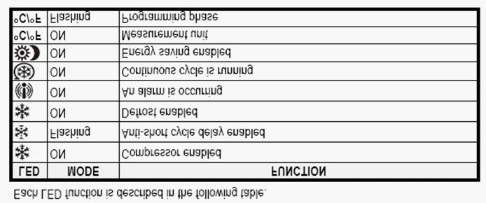
24 Handle Installation CAUTION Handle mounting on wood overlay door should be mounted on overlay panel only (not the door) to avoid damage to the factory door. 1. Handle must be attached to overlay before mounting overlay onto door. Mark rear of wood overlay planel with handle fastening locations. 2. Drill through wood overlay panel at marked locations taking care not to damage the wood overlay panel. 3. Countersink screw heads so screw heads are flush with backside of panel. Attach handle to overlay panel. CAUTION Proper wood working materials and equipment should be used to avoid damage or errors in workmanship. Wood Overlay Panel Installation Scan the QR code to the right with your smart phone to watch a How-To video on how to install Wood Overlay panels onto Perlick doors, otherwise, follow the instructions below. OPERATION General The unit is equipped with a state-of-the-art refrigeration system. The variable speed compressor automatically changes speed based on system conditions and load. The cabinet is equipped with an adjustable digital temperature controller and LED display. Freezer units are frost-free models, meaning the evaporator coil automatically defrosts on demand at predetermined intervals. The controller also has a manual defrost soft button on the front panel signified by a melting snowflake. If depressed it will automatically put the system into a defrost cycle. Interior Light The unit is equipped with an interior light that illuminates when the door is open. The cabinet also comes standard with a manual light switch located next to the light for displaying your products through a glass door. Always ensure that the manual switch is in the off position before closing a solid wood or stainless door. If manual light switch is left on for an extended period of time it may increase the cabinet temperature, especially at the top and cause the refrigeration system to run longer. Loading Product 1. With the unit secured in position, open the door and make sure panel s pre-drilled holes align with door frame holes. 2. Loosely attach four corners of the overlay panel to the door using #10 x 1 wood screws, installed through the door frame from the rear. 3. Check for overall wood overlay panel fit, position and function. Make minor adjustments as necessary. When panel is properly aligned, tighten mounting screws securely. Install the rest of the mounting screws and tighten securely. CAUTION Do not over-tighten wood overlay attachment screws as this may damage the factory supplied door frame. IMPORTANT NOTE: Before storing perishables, allow unit to run for a minimum of 24 hours to allow temperature stabilization after start-up. When loading items into the unit, do not block internal louvers and fan guard openings or performance will be decreased. LIGHT BULB REPLACEMENT To replace a defective or burnt out light bulb, unscrew the bulb counterclockwise and replace with an identical 15-watt bulb or smaller (Perlick replacement bulb number 67026). 24

25 TEMPERATURE CONTROLLER 25
26 IMPORTANT NOTE: Dependent on the mode and configuration, the controllers have been programmed to only allow a temperature adjustment within a specified range. See chart below for the specified range allowed for your cabinet: Single Door Units Description Model No. Set Point Range 15 Beer Dispenser HP15TS 38 F 30 F to 42 F 24 Beer Dispenser HP24TS 38 F 30 F to 42 F Two Door Units Description Model No. Set Point Range 48 Refrigerator/Beer Dispenser HP48RT 38 F 30 F to 42 F IMPORTANT NOTE: All mutli-zone units must have a minimum of 8 F difference between zones. CHECKING PRODUCT TEMPERATURE To accurately check the temperature of product stored in the refrigerated compartment insert an accurate thermometer into a plastic (non-breakable) bottle, partially filled with water. Tighten the bottle cap securely. Place the bottle in the desired area for 24 hours. Refrain from opening the unit during testing period. After 24 hours, check the temperature of the water. Adjust the control settings if necessary. You Perlick unit is pre-set in order to achieve the recommended temperature range when installed in a 70 F ambient room temperature. Factors which affect the internal temperatures of the refrigerated cabinet include: Temperature setting Room temperature where installed Number of times the door is opened and closed Length of times the door is left open Style of door installed Door gasket sealing and condition Amount of time the internal light is illuminated Installaion in direct sunlight or near a heart source CLEANING AND OTHER MAINTENANCE CAUTION Shut off electricity to the unit before cleaning the condenser and other routine maintenance. To clean stainless steel exterior or interior surfaces, use a soft, nonabrasive stainless steel cleaner to wipe down the surfaces. If you have difficulty finding a good cleaner, try Signature Polish from Signature Limited Laboratory, P.O. Box 13436, Dayton, OH ; or call toll-free at (877) Glass panels can be cleaned using any standard glass cleaner available on the market today. To clean interior and exterior non-metallic surfaces and removable parts, wash with a mild solution of soap and lukewarm water with a little baking soda. Rinse and dry thoroughly. Avoid getting water on lights, controllers, fan motors and unfinished wood wine rack faces. CAUTION Do not use abrasive cleaners or cloths on any of the interior or exterior surfaces or removable parts. Cleaning the Condenser The condenser should be cleaned every three (3) months. The condenser is located behind the toe plate (Figure 6). Remove the toe plate and use a soft bristle brush and vacuum to remove the dust and lint. Avoid damaging or crushing the condenser fins or tubing. Upon completion, reinstall the toe-plate. CAUTION Failure to clean the condenser could result in temperature loss or mechanical failure. Clean this area every three months. 26
27 INSTALLING DISPENSING EQUIPMENT Open tapping kit box and become familiar with its components. If the dispensing head is going to be mounted on a counter top directly above the refrigerated cabinet, have the countertop predrilled using the supplied template or the template provided on page 30. Make sure that the access hole in the refrigerated cabinet is in line with the counter top holes. Remove any obstructions from the access hole of the refrigerator. Follow instructions on pages 28 and 29 to properly install the tapping equipment on your Perlick unit. Dispensing head Apply silicone to bottom perimeter Faucet lead Drainer Air distributor Flange sleeve All hose connections use worm-drive hose clamps (view enlarged to verify) Beer connection Keg Keg coupler NOTE: Image does not accurately reflect positions of the different elements within the unit. Positions and hose lengths showns are to clearly illustrate proper connection methods only. Distributor is only on multiple keg units, each keg is connected to a valve on the air distributor. Single keg is connected directly to the regulator. 27
, and hose clamp(s).")

 through the hole in the counter top.")


28 BEFORE YOU BEGIN... Wash tapping devices thoroughly. Flush beer and faucet lines and tapping device (keg coupler) with fresh water. 1. Locate the dispensing head, black beer line(s), and hose clamp(s). Slide one end of each beer line onto the stainless steel tubes which protrude out the bottom of the dispensing head and clamp tight. 4. If installing a two or three faucet system, a CO2 manifold will need to be installed. Locate the plastic manifold holding bracket and a #10 x ½ sheet metal screw. On the left rear side wall of the beer compartment there is a double row of screws which run vertically. Remove one of the two top screws and discard. Insert the sheet metal screw through the bracket and into the hole vacated previously. 2. Insert the beer line(s) through the hole in the counter top. Position the head in place and apply silicone around the base of the dispensing head. Fasten using the 4 chrome screws included with the dispensing head. Wipe off excess silicone to complete the seal. 5. Locate the red CO2 lines, manifold and clamps. Slide one end of each hose onto the barbed fittings on the manifold and clamp. Insert the manifold into the bracket and secure by squeezing the two sides together. 3. Using the 3/8 thick foam pad included in the tapping kit, roll into a cylinder. From inside the cabinet, insert the foam tube up through the hole in the ceiling of the cabinet, through the hole in the counter top until it is firmly against the insulation in the dispensing head. Cut away any excess pad. Cut away any excess foam that extends into the cabinet that extends into refrigerator. 6. On a single beer system, locate the red CO2 hose. Slide one end onto the barbed fitting of the regulator assembly and clamp. On systems with two or three beers, locate the CO2 line that comes off the back side of the manifold assembly. This is the hose not connected to a valve assembly. Slide the hose end onto the barbed fitting of the regulator assembly and clamp. For detailed information on connecting the regulator to the CO2 cylinder, see page


29 7. Locate the keg coupler(s). Slide one of the red CO2 lines onto the larger barbed fitting of coupler and clamp. Locate one of the black beer lines and slide onto the smaller barbed fitting of the coupler and clamp. Repeat for additional couplers. 10. Locate beer faucet(s) and install onto the dispensing head shanks. Tighten with supplied spanner wrench. Install black handle(s) onto faucet(s). 8. On the right rear sidewall there is a double column of screws. Remove the center rear screw. Locate the safety chain and a #10 x ½ sheet metal screw from the parts bag. Insert the screw through the closed end link of the chain and tighten in the vacant screw hole. The chain can now be used to secure the tank, preventing damage to the regulator. 11. Before tapping, make sure the beer faucet is closed. To tap a keg, insert the coupler into the fitting on top of the barrel. Turn the coupler clockwise until it stops (about 1/8 turn). Then push down on the top of the coupler and again turn clockwise until it stops. Your barrel is now tapped. Open the CO2 valve on the regulator as well as the valve on the manifold if used. Using Soap and water solution, check all CO2 connections for leaks indicated by bubbles. Tighten as needed. 9. CO2 tanks are shipped empty and must be filled prior to uses. Turn the adjusting screw on the regulator counterclockwise one turn. Make sure that the valve at the bottom of the regulator where the red hose is connected is in the off position as shown. Open the tank valve. Watching the secondary pressure gauge, turn the regulator adjusting screw clockwise until the pressure is at 10 psig. Adjustments can later be made based on flow rates. 29
30 30
31 CONNECTING THE REGULATOR TO THE CO2 CYLINDER REPLACING THE CO2 GAS CYLINDER 1. Turn CO2 hand valve clockwise until seated and close shutoff valve on regulator. 2. Unscrew regulator from cylinder fitting. 3. Replace carbonic washer (Part No. 157F2P), if needed, and reattach regulator to filled cylinder. 4. Turn CO2 hand valve counterclockwise until fully open. Turn regulator shut-ff valve to open position. 5. Adjust CO2 gas flow as required, turning clockwise for higher pressure. CAUTION Do not use keg coupler as a handle to lift keg. 1. Remove the blue plug from the regulator fitting. NOTE: Do not remove the carbonic washer. 2. Screw regulator onto gas cylinder valve. Tighten with wrench until vertically straight. Be sure that shut-off valve on regulator is in the OFF (horizontal) position. 3. Place screw clamp over the end of red line and push onto regulator tailpiece. Tighten clamp with a screwdriver. 4. Turn regulator adjusting screw counterclockwise until it turns freely. 5. Turn hand valve counterclockwise on the CO2 cylinder to the fully open position. 6. Turn regulator adjusting screw clockwise until desired pressure is reached (approximately lbs.) Tighten stop nut on adjusting screw. 7. Open shut-out valve on bottom of regulator. CO2 LEAK TEST Dilute a small amount of liquid dishwashing soap and rub the soapy mixture around each connection. If bubbles appear, tighten connection. PROPER CO2 HANDLING ALWAYS... Connect a regulator (reducing valve) to CO2 cylinder. Secure cylinder in upright position whether in storage or in use. Keep cylinder away from heat. Rupture disc vents at 122 F maximum. Ventilate room after gas leakage. Check the last DOT test date on cylinder neck before filling. If more than five years old, the cylinder must be retested to DOT specifications. Be sure CO2 cylinder outlet fitting is free of dust or dirt before attaching regulator. Store CO2 cylinder and regulator assembly upright. Allow only properly trained and experienced personnel to handle high pressure gas. NEVER... Connect cylinder directly to a keg without a regulator (reducing valve) Drop or throw regulator or CO2 cylinder. Transport CO2 cylinder in a closed vehicle. Apply oil to a regulator. Shut off CO2 cylinder when not in use. You will not save gas by doing so! Allow untrained, inexperienced personnel to handle high pressure gas. CAUTION Be sure to close the gas shut-off valve when untapping the keg. 31

32 TAPPING A SINGLE VALVE KEG (Sankey) TAPPING A SINGLE VALVE KEG ( Low Profile Coupler) BEER OUT GAS IN Single Valve Coupler Step 1 BOTTOM ADAPTER LUG OPENINGS KEG LUGS KEG NECK Step 2 Step 3 Be sure beer faucet is in closed position. Align keg lug openings on bottom of coupler. Turn clockwise 1/4 turn. Pull handle out and down. Keg is now tapped. Open shut-off valve on air divider located inside of the cabinet. IMPORTANT Be sure to close the gas shut-off valve when untapping a keg. To tap, place bottom adapter in extended position, align lug openings and insert into keg, turning clockwise to stop. To open beer valve, push down and turn clockwise to second stop. IMPORTANT Be sure to close the gas shut-off valve when untapping a keg. TEMPERATURE One of the most common causes of dispensing problems is improper temperature. Draft beer should be stored at a temperature between 32 F and 38 F. At warmer temperatures, beer will foam. At temperatures lower than 30 F, beer will freeze. When beer freezes, the alcohol in the beer may separate and cause beer to be cloudy with an off taste. HOW TEMPERATURE DRAFT AFFECTS BEER Freezes Ideal Foams
33 CLEANING THE BEER SYSTEM The entire beer system, to include the faucet, flexible beer line and tapping devices must be cleaned at regular intervals. We recommend flushing the entire system with fresh water immediately after a keg has been emptied. Once each month the system should be cleaned chemically. It is recommended that you purchase Perlick s Pump Type Sterilizer, as shown below. It is equipped with an adapter that attaches directly to the faucet shank in lieu of the faucet. Part No. Description Beer line cleaning kit BLC4 BLC32 4 oz. Cleaner 32 oz. Cleaner Cleaning the draft beer system will help to eliminate the buildup of the following: Bacteria Beer is an excellent food for bacteria (none of which is harmful). Proper conditions may begin the growth of bacteria in the draft beer and on the beer faucet. By regular cleaning, we prevent this bacteria buildup and maintain the quality of the draft beer. Greenish or yellowish colored material on the faucet may indicate bacterial growth. Yeast All domestic draft beers contain a small amount of yeast which remains in the beer from the fermentation process. When the temperature of the draft beer exceeds 50 F, a process of secondary fermentation may take place. The beer faucet may exhibit a white colored substance (yeast buildup) if not cleaned on a regular basis. Beer Stone All beer contains calcium which is present from the grains used in the brewing process. It is an important natural material in draft systems in that as it oxidizes, it s coats the internal parts of the beer line and equipment. This thin coat of beer stone helps prevent the beer from picking up a strong metallic or plastic flavor as it flows through the system. The beer stone will continue to build if the system is not cleaned properly or regularly and can cause drawing problems if it begins to flake off. Beer stone is present if one can see a brownish color on the faucet or inner wall of the beer line, or tobacco-like flakes in the beer. BEER SERVICE PROBLEMS Wild Beer Problem: Dispensed beer either has too much foam or is all foam. Causes: Beer has been dispensed improperly- Solution: See pouring instructions on page 33 Regulator pressure is set too high Warm keg temperature- Solution: Keg must be colder than 40 F. Target temperature is between 36 and 38 F Cabinet door is opened and closed frequently and the temperature is warmer than 38 F- Solution: Adjust temperature to between 36 and 38 F. Kinks, dents or obstructions in the line Using oddly shaped glasses. Frosted, waxed or styrofoam containers also may cause foaming. Dispenser has been turned off for a long period of time. Faucet is bad, dirty or in a worn condition. Regulator malfunction Flat Beer Problem: Foamy head disappears quickly; beer lacks brewery fresh flavor. Causes: Dirty glassware CO2 pressure is too low due to leak or pressure setting. CO2 is turned off at night Cooler is too cold CO2 leak or defective (sticking) check valve Sluggish CO2 regulator Cloudy Beer Problem: Beer in glass appears hazy, not clear. Causes: Dirty glassware Dirty faucet or beer line Frozen or nearly frozen beer Old beer Beer has not been refrigerated for a long period of time. BEER AND CO2 FACTS Beer foam is 25% liquid beer and 75% CO2 gas. Don t waste it all! Most people prefer beer stored at 38 F. Beer lines and faucets require regular cleaning (see cleaning instructions on page ###). A fully-charged 4.2 lb. CO2 cylinder will dispense approximately 5-1/2 or 6-1/2 barrels. CO2gas gives beer its sparkling effervescence. It also gives beer its creamy head of foam. 33
34 POURING THE PERFECT GLASS OF BEER STEP ONE Start with a clean glass. Place the glass at a 45 angle, one inch below faucet. Do not let the glass touch the faucet. Open the faucet all the way. STEP TWO Start with a clean glass. Place the glass at a 45 angle, one inch below faucet. Do not let the glass touch the faucet. Open the faucet all the way. STEP THREE Let the remaining beer run straight down the middle of the glass. This ensures proper release of CO2 by producing a 3/4 to 1 foam head. STEP FOUR Close the faucet quickly and completely. 34
35 TROUBLESHOOTING BEFORE CALLING FOR SERVICE: If the unit appears to be malfunctioning, read through NORMAL OPERATION first. If the problem persists, check the TROUBLESHOOTING GUIDE. Locate the problem in the guide and refer to the cause and its remedy before calling for service. The problem could be something which can be solved without a service call. DANGER NEVER ATTEMPT TO REPAIR OR PERFORM MAINTENANCE ON THE UNIT UNTIL THE MAIN ELECTRICAL POWER HAS BEEN DISCONNECTED! Problem: No interior light Is the bulb loose? Is the bulb burnt out? Problem: Light stays on when door is closed Manual ON/OFF light switch is turned ON Is the door switch making contact with the door? Problem: Noise during operation Certain sounds are normal. Soft sounds from the compressor, fan motor and valves will be heard During freezer defrost crackling is normal Problem: Controller display is flashing P1 There is a thermostat probe failure Problem: Controller display is flashing P2 There is an evaporator probe failure Problem: Controller display is flashing HA The internal compartment temperature has exceeded the high temperature alarm preset value for over 30 minutes. Check to ensure door is closed Check door gasket seal Has warm product been placed in the cabinet? Is the condenser clean? In the louvered toe plate obstructed? Has the surrounding ambient temperature changed dramatically? Is the interior light ON? Problem: Controller display is flashing LA The internal compartment temperature has exceeded the low temperature alarm preset value for over 30 minutes Check to ensure door is closed Check for gasket seal Has the surrounding ambiant temperature changed dramatically? Problem: Controller display is flashing EE The controller has a data or memory failure Problem: The refrigerated cabinet isn t running Is there electrical power to the unit? Is your home circuit breaker or fuse on? Is your ON/OFF key pad on? Is your condenser area clean? 35
36 Problem: The refrigerated compartment is warmer than usual Is your control set properly? Is the light staying on? Is your condenser area clean and free of obstructions? Has the door been open for a long time or more frequent door openings occured? Are the internal louvers and fan guard openings obstructed? Has warm product been placed in the cabinet? Problem: The refrigeration system runs for long periods of time Is the condenser area clean and free of obstructions? Have the doors been open for a long time or more frequent door openings occured? Has warm product been placed in the cabinet? On hot days and in warm room temperatures the system will run long Problem: Condensation forms inside the refrigerated compartments This is normal during high humidity and frequent door openings Are the doors closing and sealing properly? Problem: Condensation forms on the outside of the unit During periods of high humidity some condensation might appear on outside surfaces. The condensation will disappear when the humidity drops. Meanwhile, be sure doors are closing and sealing properly. If condensation persists, contact your Perlick Factory Authorized Service Center. You need product information: Contact your selling dealer Inquire via the web at Call (800) for factory assistance on planning, installation or product information. Write to: Perlick Corporation, Customer Service Department, 8300 West Good Hope Road, Milwaukee, WI us at warrantyserv@perlick.com You need product service: Check the model and serial number of your unit located on the label attached to the inside top of the cabinet. Then call your Perlick FactoryAuthorized Service Center. For the location of the Service Center in your area, contact your dealer, inquire via the web at call (800) for factory assistance on planning, installation or product information, write to: Perlick Corporation, Customer Service Department, 8300 West Good Hope Road, Milwaukee, WI 53223, us at warrantyserv@perlick.com. You need replacement parts or accessories: Use only genuine Perlick replacement parts and accessories. Genuine Perlick parts and accessories are designed to work correctly with Perlick products and offer superior service life. The use of non-perlick parts can damage the unit and may void the warranty Check the model and serial number of your unit located on the label attached to the inside top of the cabinet. Then call your Perlick Factory Authorized Service Center. For the location of the Service Center in your area, contact your dealer, inquire via the WEB at or write to: Perlick Corporation, Customer Service Department, 8300 W. Good Hope Rd, Milwaukee, WI 53223, call 800/ or us at warrantyserv@perlick.com 36
37 RESIDENTIAL PRODUCTS WARRANTY 1A. PERLICK RESIDENTIAL REFRIGERATION PRODUCTS LIMITED WARRANTY (excludes H50IM Clear Ice Makers; see warranty on page 31) ENTIRE PRODUCT - Full Three Year Warranty*: For three (3) years from date of original purchase, Perlick Corporation s warranty covers all parts and labor to repair or replace any part of the product, which proves to be defective in material and workmanship. ADDITIONAL - Fourth through Sixth Year Limited Parts Only Warranty: During the three (3) years following expiration of the Three Year Warranty*, Perlick will supply replacement parts only for the hermetically sealed refrigeration system with consists of the compressor, condenser, drier, connecting tubing, evaporator and hot gas bypass valve. *You must register your product within 90 days of purchase to receive the Full Three Year Warranty. Without registration, you will receive the standard Full Two Year Warranty with the additional Third through Sixth Year Limited Parts Only Warranty. TERMS: The Perlick Warranty applies to products installed in the fifty United States, the District of Columbia or the ten provinces of Canada. All service provided by Perlick Corporation under the above warranty must be performed by authorized Perlick service representatives, unless otherwise specified by Perlick. Service will be provided in the home during normal business hours. This warranty applies only to products installed for normal residential use, it does not include adjusting the controls, door reversal, light bulb or cleaning the condenser. This warranty is extended only to the original purchaser of the Perlick product. The above warranty does not apply if: Failure of product was due to transportation Product was: improperly installed, misused, abused, operating with low voltage, wiring not conforming to electrical codes, improperly maintained or modified. The original Bill of Sale, delivery date or serial number cannot be verified. Defective parts are not returned for inspection if so required by the Perlick Corporation. To receive parts and or service and the name of the nearest Perlick authorized service representative, contact your Perlick dealer, distributor or Perlick Corporation s Customer Service Department; 8300 West Good Hope Road, Milwaukee Wisconsin, 53223; call , us at warrantyserv@perlick.com, or visit our web: This limited warranty is in lieu of any other warranty, expressed or implied, including, but not limited to any implied warranty of merchantability or fitness for a particular purpose; provided however, that to the extent required by law, implied warranties are included but do not extend beyond the duration of the express warranty first set above. Perlick s sole liability and your exclusive remedy under this warranty are set forth in the initial paragraph above. Perlick Corporation shall have no liability whatsoever for any incidental, consequential or special damages arising from the sale, use or installation of the product or from any other causes whatsoever, whether based on warranty(expressed or implied) or otherwise based on contract, tort or any other theory of liability. Some states do not allow limitations on how long an implied warranty lasts or the exclusion or limitation of incidental or consequential damages, so the above limitations may not apply to you. This warranty gives you specific legal rights, and you may also have other rights, which vary, from state to state. 37
 year from date of original purchase, Perlick Corporation s warranty covers all parts and labor to repair or replace any part of the product,")

38 ENTIRE PRODUCT - Full One Year Warranty: 1B. PERLICK H50IM CLEAR ICE MAKER LIMITED WARRANTY For one (1) year from date of original purchase, Perlick Corporation s warranty covers all parts and labor to repair or replace any part of the product, which proves to be defective in material and workmanship. TERMS: The Perlick Warranty applies to products installed in the fifty United States, the District of Columbia or the ten provinces of Canada. All service provided by Perlick Corporation under the above warranty must be performed by authorized Perlick service representatives, unless otherwise specified by Perlick. Service will be provided in the home during normal business hours. This warranty applies only to products installed for normal residential use, it does not include adjusting the controls, door reversal, light bulb or cleaning the condenser. This warranty is extended only to the original purchaser of the Perlick product. The above warranty does not apply if: Failure of product was due to transportation Product was: improperly installed, misused, abused, operating with low voltage, wiring not conforming electrical codes, improperly maintained or modified. The original Bill of Sale, delivery date or serial number cannot be verified. Defective parts are not returned for inspection if so required by the Perlick Corporation. To receive parts and or service and the name of the nearest Perlick authorized service representative, contact your Perlick dealer, distributor or Perlick Corporation s Customer Service Department; 8300 West Good Hope Road, Milwaukee Wisconsin, 53223; call , us at warrantyserv@perlick.com, or visit our web: This limited warranty is in lieu of any other warranty, expressed or implied, including, but not limited to any implied warranty of merchantability or fitness for a particular purpose; provided however, that to the extent required by law, implied warranties are included but do not extend beyond the duration of the express warranty first set above. Perlick s sole liability and your exclusive remedy under this warranty are set forth in the initial paragraph above. Perlick Corporation shall have no liability whatsoever for any incidental, consequential or special damages arising from the sale, use or installation of the product or from any other causes whatsoever, whether based on warranty (expressed or implied) or otherwise based on contract, tort or any other theory of liability. Some states do not allow limitations on how long an implied warranty lasts or the exclusion or limitation of incidental or consequential damages, so the above limitations may not apply to you. This warranty gives you specific legal rights, and you may also have other rights, which vary, from state to state. Form No. Z2259 Rev. 06/07/ West Good Hope Road Milwaukee, WI Toll Free Fax
Installation & Operation Manual. 24" C-Series Refrigerator Wine Reserve Beverage Center
 Installation & Operation Manual 24" C-Series Refrigerator Wine Reserve Beverage Center TABLE OF CONTENTS Introduction..............................................1 Warranty Registration......................................1
User Manual / Installation Instructions
 User Manual / Installation Instructions Outdoor Refrigerator Drawers MODEL: L24DWR Lynx Professional Grills 5895 Rickenbacker Rd., Commerce, CA 90040 Service: (888) 289-5969 Tel: (323) 838-1770 Fax: (323)
Operation & Installation Manual
 Luxury Operation & Installation Manual Signature Series (HP24- and HP48-inch models) Excludes Beer Dispenser Models HP24FS HP24RS HP24BS HP24WS HP48RR HP48RB HP48WO HP48WW Form No. Z2340 Rev. 06/04/2012
Installation & Operation Manual
 Installation & Operation Manual 24, 48 & 72 Signature Series Freezer Freezer Drawers Refrigerator Refrigerated Drawers Beer Dispenser Beverage Center Wine Reserve INTRODUCTION Congratulations on your
INSTALLATION and OPERATION INSTRUCTIONS
 INSTALLATION and OPERATION INSTRUCTIONS MODEL NOS. DC90ACLT IMPORTANT INFORMATION To register your product, visit our web site at (www.perlick.com). Click on Commercial, then Service. You will see the
Installation Manual HP15 HP24 HP48 HH24 HC24 HA24
 Installation Manual HP15 HP24 HP48 HH24 HC24 HA24 15 SIGNATURE SERIES 24 SIGNATURE SERIES 48 SIGNATURE SERIES SIGNATURE SERIES SOTTILE C-SERIES ADA-COMPLIANT SERIES Form No. Z2348-F Rev. 11.01.2017 TABLE
Installation Guide. 15 W./24 W. Undercounter Refrigeration
 Installation Guide 15 W./24 W. Undercounter Refrigeration Table of Contents Warnings & Important Information 3 Proper Disposal 4 Dimensions (15 W. Professional) 5 Dimensions (24 W. Professional) 6 Dimensions
Installation Guide. 15 W./24 W. Undercounter Refrigeration U L. Viking Range Corporation. 111 Front Street. Greenwood, Mississippi USA
 Installation Guide Viking Range Corporation 111 Front Street Greenwood, Mississippi 38930 USA (662) 455-1200 For product information, call 1-888-845-4641 U L C U L 15 W./24 W. Undercounter Refrigeration
INTRODUCTION. 1
 INTRODUCTION Congratulations on your purchase of a Perlick residential refrigeration product. A pioneer in the commercial refrigeration field for nearly 60 years, Perlick has decided to bring the ultimate
Preparing the Cabinet
 Preparing the Cabinet Uncrating and Inspection Remove all crating material before operating. Carefully inspect cabinet for hidden damage. If damage is discovered, file your claim immediately with the transport
INSTALLATION AND OPERATION INSTRUCTIONS CONCESSIONAIRE PORTABLE DISPENSERS MODEL NOS.
 INSTALLATION AND OPERATION INSTRUCTIONS CONCESSIONAIRE PORTABLE DISPENSERS MODEL NOS. DC Series IMPORTANT INFORMATION Complete the enclosed warranty card and mail to the Perlick Corporation to register
Installation. 15 W. / 24 W. Undercounter Refrigeration
 Installation 15 W. / 24 W. Undercounter Refrigeration VRCI5240G / CVRCI5240G / VRCO5240D / CVRCO5240D VRDI5240D / CVRDI5240D / VRDO5240D / CVRDO5240D VBCI5150G / CVBCI5150G / VBCI5240G / CVBCI5240G VWCI5150G
Viking Use & Care Manual
 Viking Use & Care Manual Viking Range Corporation 111 Front Street Greenwood, Mississippi 38930 USA (662) 455-1200 For product information call 1-888-VIKING1 (845-4641), or visit the Viking Web site at
INSTALLATION and OPERATION INSTRUCTIONS
 INSTALLATION and OPERATION INSTRUCTIONS 24" SINGLE DOOR Custom Series MODEL NOS. HC24RS HC24FS HC24WS * HC24RS ONLY * HC24RS HC24WS IMPORTANT INFORMATION This manual has been prepared to assist you in
Installation and User's Manual for Refrigerator Model SCR33
 Installation and for Refrigerator Model SCR33 Introduction Congratulations on your purchase of a Scotsman refrigeration product. For future reference, keep this guide in a safe, accessible location. If
L24TWS. Beverage Tower Kit Components. L24TWD Lynx Beverage Kits Model L24TWS Single Tower and L24TWD Double Tower
 Installation, Care and Use of Your Lynx Beverage Tower Kits MOM FRIENDLY. DAD READY. L24TWS Beverage Tower Kit Components L24TWD Lynx Beverage Kits Model L24TWS Single Tower and L24TWD Double Tower Introduction:
Installation Operation and Maintenance Instructions
 MARVEL Installation Operation and Maintenance Instructions Keg Dispenser 61HK 6OHK TABLE OF CONTENTS Unpacking your refrigerator...2 Removing the packaging...2 Warranty Registration...2 Installing your
Use and Care Manual. For Beverage Cooler RU
 Use and Care Manual For Beverage Cooler RU 500 7081 619-01 Congratulations on your purchase. Choosing this appliance means you want all the benefits of state-of-the-art refrigeration technology, guaranteeing
4.9 CU.FT. BEER KEG COOLER INSTRUCTION MANUAL. Model No.: MCKC490S
 4.9 CU.FT. BEER KEG COOLER INSTRUCTION MANUAL Model No.: MCKC490S To ensure proper use of this appliance and your safety, please read the following instructions completely before operating this appliance.
Table of Contents. Specifications... page 2. Installation... page 3. Customizing... page 4. Reversing door swing... page 5
 Introduction The Scotsman Compact Refrigerator is a unique product, capable of being built into a cabinet because of its front vented, forced-air cooling system. It s also designed to be a companion to
INSTALLATION and OPERATION INSTRUCTIONS
 INSTALLATION and OPERATION INSTRUCTIONS SINGLE DOOR freezer MODEL NOS. FN FS Finished Stainless Steel Top Non-Finished Top FS FN IMPORTANT INFORMATION This manual has been prepared to assist you in the
CHEST FREEZER INSTRUCTION MANUAL. Model No.: EWCF5WBX EWCF7WBX
 CHEST FREEZER INSTRUCTION MANUAL Model No.: EWCF5WBX EWCF7WBX To ensure proper use of this appliance and your safety, please read the following instructions completely before operating this appliance.
Ui REFRIGERATOR SPEC SHEET
 Ui REFRIGERATOR SPEC SHEET ISOMETRIC VIEW 19 7/8 20 1/2 32 3/4 FRONT VIEW NOTES: 1. CUTOUT DIMENSIONS: 20 1/2"W X 33"L X 20 3/4"D 2. CUTOUT DIMENSIONS ARE FOR REFRIGERATOR ONLY. REFER TO STAINLESS STEEL
READ ALL INSTRUCTIONS CAREFULLY BEFORE STARTING INSTALLATION OR OPERATION.
 ICE MAKER INSTALLATION INSTRUCTIONS & OWNER S MANUAL INSTALLER: Leave these instructions with consumer. CONSUMER: Retain for future reference. Model # 3592 IMPORTANT: READ ALL INSTRUCTIONS CAREFULLY BEFORE
BEFORE USE, PLEASE READ AND FOLLOW ALL SAFETY RULES AND OPERATING INSTRUCTIONS.
 INSTRUCTION MANUAL Model Number: BLZ-SSRF130 BEFORE USE, PLEASE READ AND FOLLOW ALL SAFETY RULES AND OPERATING INSTRUCTIONS. 1 TABLE OF CONTENTS REFRIGERATOR SAFETY 3 IMPORTANT SAFEGUIDES 4 PARTS AND FEATURES
USE/INSTALLATION INSTRUCTIONS VRBD/VUBD 24 W. BEVERAGE DISPENSER
 USE/INSTALLATION INSTRUCTIONS VRBD/VUBD 24 W. BEVERAGE DISPENSER Retain for Future Reference VIKING RANGE CORPORATION 111 Front Street Greenwood, Mississippi 38930 USA (662) 455-1200 IMPORTANT - PLEASE
BEFORE USE, PLEASE READ AND FOLLOW ALL SAFETY RULES AND OPERATING INSTRUCTIONS
 WINE CELLAR Model SWC1840 Owner s Manual BEFORE USE, PLEASE READ AND FOLLOW ALL SAFETY RULES AND OPERATING INSTRUCTIONS Write the Serial Number here Felix Storch, Inc. Summit Appliance Division An ISO
Undercounter Refrigeration
 INSTALLATION GUIDE Undercounter Refrigeration Contents Undercounter Refrigeration..................... 3 Undercounter Specifications.................... 4 Site Preparation..............................
Viking Use/Installation Guide
 Viking Use/Installation Guide Viking Range Corporation 111 Front Street Greenwood, Mississippi 38930 USA (662) 455-1200 For product information, call 1-888-VIKING1 (845-4641) or visit the Viking Web site
INSTALLATION & OPERATING INSTRUCTIONS MODEL #17900 KEGERATOR MANUAL
 INSTALLATION & OPERATING INSTRUCTIONS MODEL #17900 KEGERATOR MANUAL TABLE OF CONTENTS PAGE # SAFETY INSTRUCTIONS......... 2 INSTALLATION INSTRUCTIONS................... 3 CABINET LOCATION GUIDELINES...
Use and Care Manual. Flammable Material Storage Refrigerator LRBFS06W1HC
 Use and Care Manual Flammable Material Storage Refrigerator LRBFS06W1HC 7085 471-00 Table of Contents Table of Contents Page Please Read and Follow these Instructions... 2 California Proposition 65...
Use & Care Manual. 15 W./24 W. Undercounter Refrigeration
 Use & Care Manual 15 W./24 W. Undercounter Refrigeration Congratulations We hope you will enjoy and appreciate the care and attention we have put into every detail of your new, state-of-the-art refrigerator.
STRUCTURE ILLUSTRATION...3 IMPORTANT SAFETY INSTRUCTIONS 4 INSTALLATION INSTRUCTION..4 OPERATING YOUR REFRIGERATOR...5-6
 TABLE OF CONTENTS STRUCTURE ILLUSTRATION....3 IMPORTANT SAFETY INSTRUCTIONS 4 INSTALLATION INSTRUCTION..4 OPERATING YOUR REFRIGERATOR...5-6 FREEZER COMPARTMENT OPERATION 6 CARE & MAINTENANCE..7 CHANGING
INSTRUCTION MANUAL (UNIT APPEARANCE MAY VARY FROM IMAGE) BEFORE USE, PLEASE READ AND FOLLOW ALL SAFETY RULES AND OPERATING INSTRUCTIONS.
 BEFORE USE, PLEASE READ AND FOLLOW ALL SAFETY RULES AND OPERATING INSTRUCTIONS.") INSTRUCTION MANUAL Model Number: FR551 REFRIGERATOR-FREEZER (UNIT APPEARANCE MAY VARY FROM IMAGE) BEFORE USE, PLEASE READ AND FOLLOW ALL SAFETY RULES AND OPERATING INSTRUCTIONS. Igloo has a policy of continuous
INSTRUCTION MANUAL Model Number: FR551 REFRIGERATOR-FREEZER (UNIT APPEARANCE MAY VARY FROM IMAGE) BEFORE USE, PLEASE READ AND FOLLOW ALL SAFETY RULES AND OPERATING INSTRUCTIONS. Igloo has a policy of continuous
Ice Maker. Model BIM25. Instruction Manual. Write Serial Number of unit here:
 Ice Maker Model BIM25 Instruction Manual Write Serial Number of unit here: Felix Storch, Inc. Summit Appliance Division An ISO 9001:2008 registered company 770 Garrison Avenue Bronx, New York 10474 www.summitappliance.com
1.7 CU.FT. REFRIGERATOR INSTRUCTION MANUAL MCBR170BMD
 1.7 CU.FT. REFRIGERATOR INSTRUCTION MANUAL Model No.: MCBR170WMD MCBR170BMD To ensure proper use of this appliance and your safety, please read the following instructions completely before operating this
Installation. Built-in Full Height Wine Cellar VCWB301
 Installation Built-in Full Height Wine Cellar VCWB301 Table of Contents Warnings & Important Information _ 3 Dimensions _ 5 Specifications _ 6 Cutout Dimensions 7 Cabinet Information _ 8 Cabinet Information
Installation & Operation Manual
 Installation & Operation Manual Glass Frosters FR Series FR48 SS shown C US Form No. Z2296 Rev. 01.16.2015 Glass Frosters Installation & Operation Manual JOB AREA ITEM NO. MODEL NO. FR24 SERIES FR36 SERIES
Compact Refrigerator. User Manual Model 3590A
 By Compact Refrigerator User Manual Model 3590A DANGER Risk of child entrapment. Before you throw away your old refrigerator or freezer, take off the doors. Leave the shelves in place so that children
Instruction Manual MODEL: GDUF Cu. Ft. Capacity 120V~, 60Hz, 115W
 Stock up on your family favorites! Upright Freezer Montgomery Ward Customer Service 3650 Milwaukee Street, Madison, WI 53714 8:00 am to Midnight, Monday through Friday Wards.com 1 888 557 3848 Instruction
INSTALLATION and OPERATION INSTRUCTIONS
 INSTALLATION and OPERATION INSTRUCTIONS Single Door cooler series MODEL NOS. CS32SB CS32SG CS32SS CS32ST IMPORTANT INFORMATION To register your product, visit our web site at (www.perlick.com). Click on
Use & Care Manual. 15 W./24 W. Undercounter Refrigeration. Viking Range, LLC 111 Front Street Greenwood, Mississippi USA (662)
") Use & Care Manual Viking Range, LLC 111 Front Street Greenwood, Mississippi 38930 USA (662) 455-1200 For product information call 1-888-845-4641, or visit online in the US at www.vikingrange.com and in
Use & Care Manual Viking Range, LLC 111 Front Street Greenwood, Mississippi 38930 USA (662) 455-1200 For product information call 1-888-845-4641, or visit online in the US at www.vikingrange.com and in
Viking Installation Guide
 Viking Installation Guide Viking Range, LLC 111 Front Street Greenwood, Mississippi 38930 USA (662) 455-1200 For product information, call 1-888-(845-4641) or visit the Viking Web site at vikingrange.com
 Installation Guide BI-98 Ice Maker www.u-lineservice.com Phone (414) 354-0300 FAX (414) 354-7905 Service & Parts Tech Lines Phone (800) 779-2547 FAX (414) 354-5696 OnlineService@U-Line.com 2005 U-Line
4.5 CU.FT. REFRIGERATOR INSTRUCTION MANUAL
 4.5 CU.FT. REFRIGERATOR INSTRUCTION MANUAL Model No.: MCBR465S To ensure proper use of this appliance and your safety, please read the following instructions completely before operating this appliance.
Installation Operation and Maintenance Instructions
 MARVEL Installation Operation and Maintenance Instructions Ice Machines 15iM 25iM TABLE OF CONTENTS Unpacking your ice machine...2 Removing the packaging...2 Warranty Registration...2 Installing your ice
Installation & Operation Manual
 Installation & Operation Manual Flat Top Bottle Cooler BC Series BC72 shown C US Form No. Z2295 Rev. 04.05.2018 JOB AREA ITEM NO. MODEL NO. BC24 SERIES BC36 SERIES BC48 SERIES BC24 shown BC72 shown BC48LT
MEDICAL FREEZER. Model FS24L INSTRUCTION MANUAL. Write Serial Number (on back of unit) here:
 here:") MEDICAL FREEZER Model FS24L INSTRUCTION MANUAL - Write Serial Number (on back of unit) here: FELIX STORCH, INC. 770 Garrison Avenue Bronx, New York 10474 www.medicalrefrigerators.com TABLE OF CONTENTS
MEDICAL FREEZER Model FS24L INSTRUCTION MANUAL - Write Serial Number (on back of unit) here: FELIX STORCH, INC. 770 Garrison Avenue Bronx, New York 10474 www.medicalrefrigerators.com TABLE OF CONTENTS
WA A Aqua Sub Bottom-load Water Cooler
 WA1-02-21A Aqua Sub Bottom-load Water Cooler 4002638 Thank you for choosing a Soleus Air Water Cooler. This owner s manual will provide you with valuable information necessary for the proper care and maintenance
INSTALLATION and OPERATION INSTRUCTIONS
 INSTALLATION and OPERATION INSTRUCTIONS Utility Coolers MODEL NOS. US4KP US10KP IMPORTANT INFORMATION This manual has been prepared to assist you in the installation of your Utility Cooler and to acquaint
2.4 Cu. Ft. Compact Refrigerator
 2.4 Cu. Ft. Compact Refrigerator User s Manual PLEASE READ THIS MANUAL CAREFULLY BEFORE USING YOUR REFRIGERATOR AND KEEP IT FOR FUTURE REFERENCE. Model MCBR240B Product Registration Thank you for purchasing
Outdoor Refrigerator USER S MANUAL
 Outdoor Refrigerator USER S MANUAL MODEL Number:BLZ-SSRF-40DH IMPORTANT:READ THIS USER S MANUAL PRIOR TO CONNECTING POWER AND USE Before the refrigerator is used, it must be PROPERLY POSITIONED, LEVELED
BEFORE USE, PLEASE READ AND FOLLOW ALL SAFETY RULES AND OPERATING INSTRUCTIONS
 FROST-FREE FREEZER Model: SCFF1842 Owner s Manual BEFORE USE, PLEASE READ AND FOLLOW ALL SAFETY RULES AND OPERATING INSTRUCTIONS Write the Serial Number here: Felix Storch, Inc. Summit Appliance Division
Installation. Leveling
 Your refrigerator was packed carefully for shipment. Remove and discard shelf packaging and tape. Do not remove the serial plate. Location Do not install refrigerator near oven, radiator or other heat
Use and Care Guide. Ice Maker Models: BI95, BI98, SP18 BI95 BI98 SP18
 Use and Care Guide Ice Maker Models: BI95, BI98, SP18 BI95 BI98 SP18 1 Introduction Congratulations on your purchase of a U-Line refrigeration product. A pioneer in the field for more than 40 years, U-Line
REFRIGERATOR SAFETY. Your safety and the safety of others are very important.
 REFRIGERATOR SAFETY Your safety and the safety of others are very important. We have provided many important safety messages in this manual for your appliance. Always read and obey all safety messages.
Wine Cellar. Instruction Booklet. Model: WC-2038
 Wine Cellar Instruction Booklet Model: WC-2038 IMPORTANT SAFEGUARDS Before the appliance is used, it must be properly positioned and installed as per the instruction in the Installation section. To reduce
MODULAR REFRIGERATOR. Français p. 16 Español p. 31 ITEM # MODEL #BG179B
 ITEM #0103339 Master Forge & M Design is a registered trademark of LF, LLC. All rights reserved. IMPORTANT READ THIS USER'S MANUAL PRIOR TO CONNECTING POWER AND USE. MODULAR REFRIGERATOR MODEL #BG179B
CR24 INSTALLATION INSTRUCTIONS
 CR24 INSTALLATION INSTRUCTIONS PERLICK COLLECTION 24 COLUMN REFRIGERATION To prevent appliance damage and injury, read these instructions thoroughly prior to installation. FORM NO. Z2496 REV. A-11/29/2017
FROST FREE REFRIGERATOR INSTRUCTION MANUAL
 FROST FREE REFRIGERATOR INSTRUCTION MANUAL Model No.: MCBR1010W MCBR1010S To ensure proper use of this appliance and your safety, please read the following instructions completely before operating this
INSTALLATION INSTRUCTIONS
 INSTALLATION INSTRUCTIONS BUILT-IN BOTTOM MOUNT REFRIGERATOR/FREEZER DBRTGK72SS-GRILLE KIT (FOR designer SERIES ONLY) VIKING RANGE CORPORATION 111 Front Street Greenwood, Mississippi (MS) 38930 USA (662)
English. Your Model Number is: HD1500 IMPORTANT
 Your Model Number is: HD1500 IMPORTANT Attention Valued Customer: The serial number of your machine and date of purchase is necessary information to facilitate warranty claims and the ordering of replacement
Outdoor/Commercial Refrigerator USER S MANUAL
 Outdoor/Commercial Refrigerator USER S MANUAL MODEL Number:BLZ-SSRF40D IMPORTANT:READ THIS USER S MANUAL PRIOR TO CONNECTING POWER AND USE Before the refrigerator is used, it must be PROPERLY POSITIONED,
52 BERKSHIRE CEILING FAN
 52 BERKSHIRE CEILING FAN Owner s Manual Models #20223, 20224 If a problem cannot be remedied or you are experiencing difficulty in installation, please contact the Service Department: 1-877-459-3267, 9
52 CEILING FAN. Owner s Manual Models #50336, 50337
 52 CEILING FAN Owner s Manual Models #50336, 50337 If a problem cannot be remedied or you are experiencing difficulty in installation, please contact the Service Department: 1-877-706-3267, 9 a.m.- 5 p.m.
Use and Care Manual. Beverage Cooler RU
 Use and Care Manual Beverage Cooler RU 500 7081 205-00 Congratulations on your purchase. Choosing this appliance means you want all the benefits of state-of-the-art refrigeration technology, guaranteeing
InstructIon Manual KrEs EQuIPMEnt stands
 Instruction Manual Instruction Manual SELF-CONTAINED AND REMOTE Kairak KRES model refrigerated equipment stand units are available in many lengths from 36 to 120 inches long. These units are available
OUTDOOR ICE MAKER Model BIM24OS
 OUTDOOR ICE MAKER Model BIM24OS Write Serial Number of Unit Here: SUMMIT APPLIANCE DIVISION FELIX STORCH, INC. 770 Garrison Avenue Bronx, NY 10474 USA TEL 718-893-3900 FAX 718-842-3093 www.summitappliance.com
User Manual. Wine Cellar
 User Manual Wine Cellar MODEL: WWT060MB WWT080MB WWT100MB WWT120MB 1. READ these instructions carefully before installing and operating the Wine Cellar. Keep them for further reference. 2. Record in the
SS1095 Ice Maker.
 Installation Guide SS1095 Ice Maker www.u-lineservice.com Phone (414) 354-0300 FAX (414) 354-7905 Service & Parts Tech Lines Phone (800) 779-2547 FAX (414) 354-5696 OnlineService@U-Line.com 2008 U-Line
TABLE OF CONTENTS. Safety Information...3. Installation Instructions...4. Reverse Refrigerator Door...5. Care and Maintenance... 9
 AB13582 TABLE OF CONTENTS Safety Information..........3 Installation Instructions.........4 Reverse Refrigerator Door.........5 Care and Maintenance.... 9 Troubleshooting.....11 Technical Data and Wiring
Owner s Manual 33-bottle Under-Counter Wine Cooler Model: WC-3302US
 Owner s Manual 33-bottle Under-Counter Wine Cooler Model: WC-3302US Please read this manual carefully before use and keep in a safe place for future reference. IMPORTANT SAFETY INSTRUCTIONS WARNING To
ST. KITTS CEILING FAN
 ITEM #0845047 ST. KITTS CEILING FAN MODEL #40829 Questions, problems or missing parts? Before returning this item to your retailer, call our customer service department at 1-800-643-0067, Monday - Thursday,
(rev. 07/01/14)
") All products are trademarks of Nostalgia Products Group, LLC. Worldwide design & utility patented or patents pending. 2014 2012 Nostalgia Products Group, LLC. www.nostalgiaelectrics.com (rev. 07/01/14)
All products are trademarks of Nostalgia Products Group, LLC. Worldwide design & utility patented or patents pending. 2014 2012 Nostalgia Products Group, LLC. www.nostalgiaelectrics.com (rev. 07/01/14)
Installation Operation and Maintenance Instructions
 MARVEL OUTDOOR REFRIGERATED DRAWERS Installation Operation and Maintenance Instructions Outdoor 24 Refrigerated Drawers 6ORDE UNPACKING YOUR OUTDOOR REFRIGERATED DRAWERS Remove Packaging Your outdoor refrigerated
SAFETY PRECAUTIONS Read all of the instructions before using this appliance. When using this appliance, always exercise basic safely precautions,
 SAFETY PRECAUTIONS Read all of the instructions before using this appliance. When using this appliance, always exercise basic safely precautions, including the following: This appliance is designed for
USER MANUAL. Bottled Water Dispenser SAVE FOR FUTURE USE. Model #
 Model # 900161: Page 1 USER MANUAL Bottled Water Dispenser Model # 900161 TO REDUCE THE RISK OF INJURY AND PROPERTY DAMAGE, USER MUST READ THIS MANUAL BEFORE ASSEMBLING, INSTALLING & OPERATING DISPENSER.
52 STRATHMERE CEILING FAN
 52 STRATHMERE CEILING FAN Owner s Manual Models #20341 If a problem cannot be remedied or you are experiencing difficulty with installation, please contact the Service Department: 1-877-459-3267, 9 a.m.-
User Manual / Installation Instructions
 User Manual / Installation Instructions Outdoor Refrigerator MODEL: L24REF Lynx Professional Grills 5895 Rickenbacker Rd., Commerce, CA 90040 Service: (888) 289-5969 Tel: (323) 838-1770 Fax: (323) 838-1778
INSTRUCTION MANUAL. UNDERCOUNTER WINE & BEVERAGE COOLER (32 bottles capacity) MODEL:WC-30U
 MODEL:WC-30U") INSTRUCTION MANUAL UNDERCOUNTER WINE & BEVERAGE COOLER (32 bottles capacity) MODEL:WC-30U To ensure proper use of this appliance and your safety, please read the following instructions completely before
INSTRUCTION MANUAL UNDERCOUNTER WINE & BEVERAGE COOLER (32 bottles capacity) MODEL:WC-30U To ensure proper use of this appliance and your safety, please read the following instructions completely before
GCG-10. Instruction Manual. G-Series Cooler. Manual is for the following models: GCG-10-N33EB G-10-N33EB UPRIGHT COOLER
 G-Series Cooler GCG-10 UPRIGHT COOLER Manual is for the following models: GCG-10-N33EB G-10-N33EB Instruction Manual Manual is for the following models: GCG-10-N33EB G-10-N33EB Instruction Manual GCG-10
Wine Cooler. Model No. MCWC16MCG MCWC30MCG. CAUTION: Read and follow all safety rules and operating instructions before first use of this product.
 Wine Cooler Model No. MCWC16MCG MCWC30MCG Wine Cooler. Before Putting Into Use.................. Important......................... Placing and Installation.................. Description of the Appliance................
Table of Contents Welcome and Thank You Note:
 TWR210EBL/TWR215ESS TWR320EBL/TWR325ESS Thermoelectric Wine Cooler Owner s Manual This owner s manual provides instructions on safe installation, use, and maintenance. Please read it carefully and save
9.9 CU.FT. TOP MOUNT REFRIGERATOR INSTRUCTION MANUAL. Model No.: HVDR1040W HVDR1040B HVDR1040S
 9.9 CU.FT. TOP MOUNT REFRIGERATOR INSTRUCTION MANUAL Model No.: HVDR1040W HVDR1040B HVDR1040S To ensure proper use of this appliance and your safety, please read the following instructions completely before
Camarillo 52 Ceiling Fan
 Owner s Manual Camarillo 52 Ceiling Fan Part # 269263, 269259, 269287 Model # 32091, 32092, 32087 Exclusively Distributed by: HD Supply Facilities Maintenance, Ltd. Atlanta, GA 30339 2017 Made in China
Compact Refrigerator. User's Manual PLEASE READ THIS MANUAL CAREFULLY BEFORE USING YOUR REFRIGERATOR AND KEEP IT FOR FUTURE REFERENCE.
 Compact Refrigerator User's Manual Model MCBR445B2 / MCBR445S2 PLEASE READ THIS MANUAL CAREFULLY BEFORE USING YOUR REFRIGERATOR AND KEEP IT FOR FUTURE REFERENCE. Product Registration Thank you for purchasing
Dual Zone Wine Cellar
 Dual Zone Wine Cellar Instruction Booklet Model: WC-2012 IMPORTANT SAFEGUARDS Before the appliance is used, it must be properly positioned and installed as described in this manual. To reduce the risk
Installation Instructions
 Instructions For Fully Integrated NoFrost Combined Refrigerator-Freezers HC 1540/1541 7084 433-00 Important Please read and follow these instructions These instructions contain Danger, Warning and Caution
Instruction Manual. Nacho Cheese Dispenser and Warmer
 Instruction Manual Nacho Cheese Dispenser and Warmer 10700 Medallion Drive, Cincinnati, Ohio 45241-4807 USA 2013 Gold Medal Products Co. Part No. 36060 SAFETY PRECAUTIONS Page 2 INSTALLATION INSTRUCTIONS
MAYFIELD CEILING FAN LISTED E ITEM # MODEL #BTH44ABZC5C BTH44BNK5C Español p. 20 ATTACH YOUR RECEIPT HERE.
 Harbor Breeze is a registered trademark of LF, LLC. All Rights Reserved. ITEM #0331094 0331096 MAYFIELD CEILING FAN MODEL #BTH44ABZC5C BTH44BNK5C Español p. 20 ATTACH YOUR RECEIPT HERE Serial Number Purchase
SLIDER CASEMENT AIR CONDITIONER
 OWNER S GUIDE READ AND SAVE THESE INSTRUCTIONS SLIDER CASEMENT AIR CONDITIONER ROTARY CONTROL P/N 309000854 (11/03) ROOM AIR CONDITIONER WARRANTY Your product is protected by this warranty Your appliance
HT-MOSEL-51D PLEASE READ THIS MANUAL CAREFULLY BEFORE USING THE WINE CHILLER
 HT-MOSEL-51D PLEASE READ THIS MANUAL CAREFULLY BEFORE USING THE WINE CHILLER This appliance is intended to be used exclusively for the storage of wine PRODUCT RANGE PRODUCT TYPE PRODUCT SERIAL NUMBER :
INSTALLATION. Glass Panel Doors (select models) CAUTION
 CAUTION") Location Do not install refrigerator near oven, radiator or other heat source. If not possible, shield refrigerator with cabinet material. Do not install where temperature falls below 55 F (13 C) or rises
Location Do not install refrigerator near oven, radiator or other heat source. If not possible, shield refrigerator with cabinet material. Do not install where temperature falls below 55 F (13 C) or rises
DUAL VOLTAGE REFRIGERATORS 220/240 VOLTS AC AND 12/24 VOLTS DC INSTALLATION AND OWNER S MANUAL
 DUAL VOLTAGE REFRIGERATORS 220/240 VOLTS AC AND 12/24 VOLTS DC INSTALLATION AND OWNER S MANUAL Service Information If service or parts are required, contact the nearest Norcold Service Center. To find
Installation Operation and Maintenance Instructions
 MARVEL DUAL ZONE WINE CELLAR Installation Operation and Maintenance Instructions Dual Zone Wine Cellar 6SDZE UNPACKING YOUR DUAL ZONE WINE CELLAR Remove Packaging Your dual zone wine cellar has been packed
DIRECT DRAW BEER COOLERS Installation, Operation and Maintenance Instructions
 DIRECT DRAW BEER COOLERS Installation, Operation and Maintenance Instructions INSPECTION When the equipment is received, all items should be carefully checked against the Bill of Lading to ensure all crates
 PROBLEM POSSIBLE CAUSES SOLUTIONS The motor seems to run too much The lights do not work High efficiency compressor and fans The room or outdoor temperature is hot A large amount of warm food has been
Torrena 42 Ceiling Fan
 Torrena 42 Ceiling Fan Owner s Manual Part # 269268, 269269 Model # 32096, 32097 Exclusively Distributed by: HD Supply Facilities Maintenance, Ltd. Atlanta, GA 30339 2017 Made in China If you are experiencing
HOUSEHOLD FREEZER 048-GM-48303/048-GM-48304/048-GM-48305
 HOUSEHOLD FREEZER 048-GM-48303/048-GM-48304/048-GM-48305 TABLE OF CONTENTS NAMES OF THE PARTS 2 IMPORTANT SAFETY INSTRUCTIONS 3 INSTALLATION INSTRUCTIONS BEFORE USING YOUR FREEZER. 3 INSTALLING YOUR FREEZER
UNDERCOUNTER REFRIGERATORS AND FREEZERS Installation, Operation and Maintenance Instructions
 UNDERCOUNTER REFRIGERATORS AND FREEZERS Installation, Operation and Maintenance Instructions Please read this manual completely prior to installing and operating this equipment. This manual describes how