CAUTION. FCC Compliance Statement
|
|
|
- Geoffrey Knight
- 6 years ago
- Views:
Transcription
1
2 CAUTION Follow the Installation Instructions before proceeding. Set the thermostat mode to OFF prior to changing settings in setup or restoring Factory Defaults. FCC Compliance Statement This equipment has been tested and found to comply with the limits for an intentional radiator, pursuant to Part 15, subpart C of the FCC rules. These limits are designed to provide reasonable protection against harmful interference in a residential installation. This equipment generates, uses and can radiate radio frequency energy and, if not installed and used in accordance with the instructions, may cause harmful interference in radio communications. However, there is no guarantee that the interference will not occur in a particular installation. If this equipment does cause harmful interference to radio or television reception, which can be determined by turning the equipment off and on, the user is encouraged to try to correct the interference by one or more of the following measures: Reorient or relocate the receiving antenna. Increase the separation between the equipment and receiver. Connect the equipment into an outlet on a circuit different from that of the receiver. Consult the dealer or an experienced radio or TV technician for help. Notice: Only peripherals complying with FCC limits may be attached to this equipment. Operation with noncompliant peripherals or peripherals not recommended by Venstar, is likely to result in interference to radio and TV reception. Changes or modifications to the product, not expressly approved by Venstar could void the user s authority to operate the equipment. FCC - INDOOR Mobile Radio Information: To comply with FCC/IC RF exposure limits for general population / uncontrolled exposure, the antenna(s) used for this transmitter must be installed to provide a separation distance of at least 20 cm from all persons and must not be co-located or operating in conjunction with any other antenna or transmitter. This Device complies with Industry Canada License-exempt RSS standard(s). Operation is subject to the following two conditions: 1) this device may not cause interference, and 2) this device must accept any interference, including interference that may cause undesired operation of the device. i
3 Under Industry Canada regulations, this radio transmitter may only operate using an antenna of a type and maximum (or lesser) gain approved for the transmitter by Industry Canada. To reduce potential radio interference to other users, the antenna type and its gain should be so chosen that the equivalent isotropically radiated power (e.i.r.p.) is not more than that necessary for successful communication. Cet appareil est conforme avec Industrie Canada, exempts de licence standard RSS(s). Son fonctionnement est soumis aux deux conditions suivantes: 1) ce dispositif ne doit pas causer d interférences, et 2) ce dispositif doit accepter toute interférence, y compris les interférences qui peuvent causer un mauvais fonctionnement de l appareil. En vertu des règlements d Industrie Canada, cet émetteur de radio ne peut fonctionner en utilisant une antenne d un type et maximale (ou moins) Gain approuvé pour l émetteur par Industrie Canada. Pour réduire les interférences radio potentielles aux autres utilisateurs, le type d antenne et son gain doivent être choisis afin que la puissance isotrope rayonnée équivalente (PIRE) ne est pas plus de ce qui est nécessaire pour une communication réussie. We, Venstar, declare under our sole responsibility that the device to which this declaration relates: Complies with Part 15 of the FCC Rules. Operation is subject to the following two conditions: (1) this device may not cause harmful interference, and (2) this device must accept any interference received, including interference that may cause undesired operation. FCC ID: MUH-SKYPORT3 IC: 12547A-SKYPORT3 These numbers can be located on the inside of the thermostat backplate, in the upper right corner. This Voyager thermostat has the ability to receive updates to its firmware. Periodically firmware updates are released by the manufacturer to add features and/or performance enhancements. This manual was produced reflecting the most current firmware/feature set at the time of publication, firmware rev Firmware releases after rev. 1.0 may not be adequately depicted in this manual. Please refer to the appropriate website or contact your place of purchase to learn about changes to the thermostat after firmware release 1.0. MUH-SKYPORT3 ii
4 Glossary of Terms Auto-Changeover: A mode in which the thermostat will turn on the heating or cooling based on room temperature demand. Cool Setpoint: The warmest temperature that the space should rise to before cooling is turned on (without regard to deadband). Deadband: The number of degrees the thermostat will wait, once a setpoint has been reached, before energizing heating or cooling. Differential: The forced temperature difference between the heat setpoint and the cool setpoint. Heat Setpoint: The coolest temperature that the space should drop to before heating is turned on (without regard to deadband). Icon: The word or symbol that appears on the thermostat display. Mode: The current operating condition of the thermostat (i.e. Off, Heat, Cool, Auto). Non-Programmable Thermostat: A thermostat that does not have the capability of running Time Period Programming. Override: During programmed unoccupied periods, pressing the Override button will force the thermostat into occupied settings. During programmed occupied periods, pressing the Override button will force the thermostat into unoccpied settings. Programmable Thermostat: A thermostat that has the capability of running Time Period Programming. Temperature Swing: Same as Deadband. Time Period Programming: A program that allows the thermostat to automatically adjust the heat setpoint and/or the cool setpoint based on the time of the day. iii
5 Table of Contents GET TO KNOW YOUR THERMOSTAT Get to Know Your Thermostat... 1 Quick Start... 6 INSTALLATION INSTRUCTIONS Installation Instructions... 9 Sample Wiring Diagrams Test Operation USER SETUP Backlight Operation Scrolling Display Options Holiday Emergency Heat Wireless Modules Service Filter Runtimes Time Period Programming INSTALLER SETUP Setpoint Limits Timers and Deadbands Programming Fan Operation Dry Contact Operation Factory Defaults TECHNICIAN SETUP Sensor Calibration Equipment Testing Advanced Setup Table Troubleshooting INDEX iv


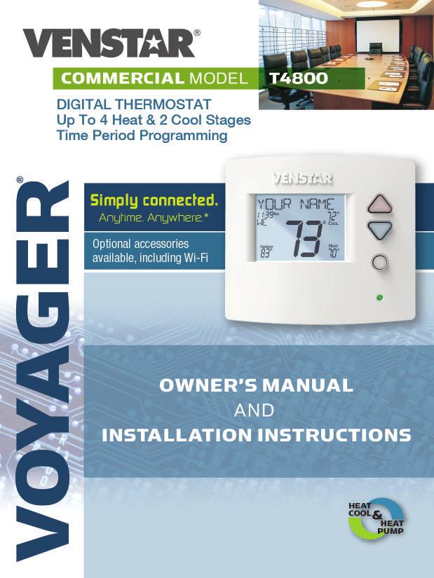
6 Get To Know Your Thermostat Optional Wireless Module Backlit, Scrolling Display Backlit Cooler & Warmer Buttons Backlit LCD Display Override Button Heat or Cool Demand Indicator Red = Heat, Green = Cool Setup Buttons Behind Door 1


7 Get To Know Your Thermostat Setup Buttons 2
8 Get To Know Your Thermostat Display Features nd3rd Program ONOFF Unoccupied Stage HI Setup 188 Step Fan On Override Outdoor AUXHEAT Lo Am 18:88Pm 1 The scrolling display will be used to help you easily navigate the setup screens in the thermostat. 2 Clock with Day of the Week Indicates the current time and day. This clock is also used to program the time period schedules. 3 Mode Indicators Selects the operational mode of the equipment. HEAT - Indicates the heating mode. COOL - Indicates the air conditioning mode. HEAT & COOL - Indicates the system will automatically change-over between heat and cool modes as the temperature varies. OFF - Indicates heating and cooling is turned off. 4 Program icon Indicates that Time Period Programming is running or is enabled to be set. 5 Room Temperature Display Indicates the current room temperature and displays the outdoor temperature when selected. 6 Outdoor icon Indicates the temperature displayed is from the optional outdoor sensor
9 Get To Know Your Thermostat Display Features nd3rd Program ONOFF Unoccupied Stage HI Setup 188 Step Fan On Override Outdoor AUXHEAT Lo Am 18:88Pm Desired Set Temperature Indicates desired room temperature(s). Also displays the highest and lowest temperatures for the day. 8 Occupied & Unoccupied icons Indicates the program number: Occupied 1, 2, 3 or Unoccupied 9 Wi-Fi icons One dot indicates the thermostat recognizes the wireless module. The pull icon indicates the thermostat is currently connected to the Local access point, via the optional Wi-Fi Module. 10 Setup Step icon Indicates the step number when the thermostat is in the setup mode. 11 2nd and 3rd Stage icons Indicates what stage of cooling or heating is currently energized. 12 icon Indicates the keypad has been locked. 4
10 Get To Know Your Thermostat Display Features 16 2nd3rd Program ONOFF Unoccupied Stage HI Setup 188 Step Fan On Override Outdoor AUXHEAT Lo Am 18:88Pm AuxHeat icon Indicates 2nd stage electric strip heat is being used when the thermostat is programmed for Heat Pump operation. Only the Aux icon will appear during Cool to Dehumidify to indicate Reheat operation. 14 Lo icon Indicates the lowest recorded outdoor temperature for the day.* 15 Hi icon Indicates the highest recorded outdoor temperature for the day.* 16 Fan On icon Indicates constant, continuous fan operation. When Fan On is not lit - indicates the fan will only operate when necessary to heat or to cool. * Hi and Lo Temperatures for the day, reset at midnight
11 Quick Start During Setup and Programming: Press the WARMER or COOLER buttons to modify the selection. Press the MODE button to advance and confirm through the setup steps. Setting the Clock and Day Not available when connected to a Skyport Account Press the SET CLOCK button. Adjust the clock using the WARMER or COOLER buttons. Press MODE to advance to the day setting. Adjust the day using the WARMER or COOLER buttons. Press the SET CLOCK button to confirm settings. TIP: To adjust the time by hours press and hold the FAN button while pressing the WARMER or COOLER buttons. WARMER Set Clock COOLER MODE Selecting the Heat or Cool Mode Select mode by pressing the MODE button. MODE Heating Only - Only the heating operation will be controlled by the thermostat in this mode. Cooling Only - Only the cooling operation will be controlled by the thermostat in this mode. Heating or Cooling (Auto-Changeover) - AUTO will automatically select heat or cool based on room temperature demand. OFF - OFF indicates both heating and air conditioning systems are turned off. 6
12 Quick Start Selecting your desired temperature AUTO-CHANGEOVER MODE - Pressing the WARMER or COOLER buttons in Auto mode will adjust both the heat and cool setpoints simultaneously. To adjust heat and cool setpoints individually, choose HEAT mode to adjust the heat setpoint and COOL mode to adjust the cool setpoint, then return to AUTO mode. HEAT OR COOL MODE - Pressing the WARMER or COOLER buttons in Heat or Cool mode will adjust only the heat or cool setpoints individually displayed. Using the Fan Button Fan On indicates constant fan operation. Fan On is not allowed when the thermostat is in the OFF mode. Pressing the FAN button toggles this feature on or off. Fan auto will allow the fan to run only when there is a heat or cool demand. FAN ON AUTO Using the Override Button NOTE: Override may only be used when the thermostat is UNOCCUPIED OPERATION - OVERRIDE set to PROGRAM ON. During programmed, unoccupied periods, pressing the OVERRIDE button will force the thermostat into Occupied 1 settings for 30 minutes. Each press of the OVERRIDE button will add another 30 minutes of time for up to 4 hours. If the maximum time has been set, the next press of the OVERRIDE button will reset the timer and return the thermostat to the correct time period program for the day Occupied Operation - During programmed, occupied periods, pressing the OVERRIDE button will force the thermostat into an unoccupied period for the rest of the day. During this forced unoccupied period the OVERRIDE button will operate as described above. Current Override Hours (setup step 7) This counter keeps track of the number of hours that the thermostat is overridden into Occupied settings. Press FAN to reset. 7
13 Quick Start Viewing the Temperature Sensors OUTDOOR TEMP - Press the OUTDOOR button to view the current outdoor temperature. The high and low temperatures for the day will also be displayed. The high and low temperatures reset at 12:00 am. If connected to a Skyport account, pressing outdoor button will show the temperatures for your location if you don t have a wired sensor connected. Note: If no outdoor sensor is connected, and there isn t outdoor temperature via Wi-Fi, then 2 dashes [- -] will appear with the first button press. OUTDOOR REMOTE/SUPPLY TEMP - Press the Accessory Status button to view linked wireless and wired sensors and other accessories. Press the Accessory Status button to return to the main screen. ACCESSORY STATUS 8
14 Installation Instructions Remove and Replace the old thermostat To install the thermostat properly, please follow these step by step instructions. If you are unsure about any of these steps, call a qualified technician for assistance. Assemble tools: Flat blade screwdriver, wire cutters and wire strippers. Make sure your Heater/Air Conditioner is working properly before beginning installation of the thermostat. Carefully unpack the thermostat. Save the screws, any brackets, and instructions. Turn off the power to the Heating/Air Conditioning system at the main fuse panel. Most residential systems have a separate breaker for disconnecting power to the furnace. Remove the cover of the old thermostat. If it does not come off easily, check for screws. Loosen the screws holding the thermostat base or subbase to the wall and lift away. If you have a smart phone handy, take a photo of the wiring for future reference. Disconnect the wires from the old thermostat. Tape the ends of the wires as you disconnect them, and mark them with the letter of the terminal for easy reconnection to the new thermostat. Keep the old thermostat for reference purposes, until your new thermostat is functioning properly. 9
15 Installation Instructions Wire Connections If the terminal designations on your old thermostat do not match those on the new thermostat, refer to the chart below or the wiring diagrams that follow. Wire from the Install on the old thermostat Function new thermostat terminal marked connector marked G or F Fan G Y1, Y Cooling Y1 W1, W Heating W1/0/B Rh, R, M, Vr, A Power R C Common C O/B Rev. Valve W1/O/B* W2 2nd Stage Heat W2 Y2 2nd Stage Cooling Y2 W3 3rd Stage Heat W3 Ck1 Dry Contact Switch DRY CONTACT CKGND Dry Contact Switch DRY CONTACT * O/B is used if your system is a Heat Pump. 10
16 Installation Instructions The Voyager Thermostat Backplate R G W1/O/B W2 Y1 Y2 W3 C OUTDOOR SENSOR REMOTE SENSOR DRY CONTACT To remove the thermostat backplate: Gently separate the display from the base by pulling first from one side, then the other until the two pieces unsnap. A small screwdriver may be used, very carefully, to start seperating the two pieces. R G W1/O/B W2 Y1 Y2 W3 24 VAC return Fan relay 1st stage heat circuit 2nd stage heat circuit 1st stage compressor relay 2nd stage compressor relay 3rd stage heat circuit C OUTDOOR SENSOR REMOTE SENSOR DRY CONTACT 24 VAC common Outdoor sensor connections Remote sensor connections Dry Contact connections IMPORTANT: This thermostat requires both R (24 VAC Return) and C (24 VAC Common) be connected to the backplate terminals. 11
17 GAS O GAS/EL 1 ON ELEC B HP Installation Instructions Check Dip Switch Ensure which switch is correct for your system. Dip switches are located on the back of the thermostat. GAS O GAS/EL ON ELEC B HP 2 3 GAS O B O B OR GAS/EL ELEC ON ON ON HP OR OR GAS ELEC ON ON ON GAS/EL HP 1. When GAS/EL or HP is set for GAS/EL: This switch (GAS or ELEC) controls how the thermostat will control the Fan (G) terminal in heating mode. When GAS is chosen, the thermostat will not energize the Fan (G) terminal in heating. When ELEC is chosen the thermostat will energize the fan in heating. 2. When GAS/EL or HP is set for HP: This switch (GAS or ELEC) defines the Aux Heat type. When GAS is chosen, the auxiliary heat will not be allowed to run during heat pump operation. When using a Dual Fuel system, set this switch for GAS. When ELEC is chosen, up to two stages of auxiliary strip heat will be allowed to run. For Heat Pump Only When the GAS/EL or HP dip switch is configured for HP, this dip switch (O or B) must be set to control the appropriate reversing valve. If O is chosen, the W1/O/B terminal will energize in cooling. If B is chosen, the W1/O/B terminal will energize in heating. This dip switch configures the thermostat to control a conventional gas/electric system or a heat pump. If your system is anything other than a heat pump, leave this switch set for GAS/EL. 12
18 Installation Instructions Sample Wiring Diagrams Conventional Heating and Cooling Systems 3 Wire, Heat Only Residential & Commercial 1 Stage Heating with no Fan. R C W1/O/B GAS O GAS/EL 24VAC Power 24VAC Common 1st Stage Heat 2 3 ON ELEC B HP 4 Wire, Cool Only Residential & Commercial 1 Stage Cooling. R C Y1 G GAS O GAS/EL 24VAC Power 24VAC Common 1st Stage Cool Fan 2 3 ON ELEC B HP 5 Wire, 1 Stage Cooling, 1 Stage Heat Residential & Commercial 1 Stage Cooling, with 1 stage Gas Heat. R C W1/O/B Y1 G GAS O GAS/EL 24VAC Power 24VAC Common 1st Stage Heat 1st Stage Cool Fan 2 3 ON ELEC B HP 5 Wire, 1 Stage Cooling, 1 Stage Heat Residential & Commercial 1 Stage Cooling, with 1 stage Electric Heat. R C W1/O/B Y1 G GAS O GAS/EL 24VAC Power 24VAC Common 1st Stage Heat 1st Stage Cool Fan 2 3 ON ELEC B HP 8 Wire, 2 Stage Cooling, 3 Stage Heat Residential & Commercial 2 Stage Cooling, with 3 stage Gas Heat. R C W1/O/B W2 W3 Y1 Y2 G GAS O GAS/EL 24VAC Power 24VAC Common 1st Stage Heat 2nd Stage Heat 3rd Stage Heat 1st Stage Cool 2nd Stage Cool Fan 2 3 ON ELEC B HP 13
19 1 1 1 Installation Instructions Sample Wiring Diagrams Heat Pump Systems 5 Wire, 1 Stage Cooling, 1 Stage Heat Residential & Commercial Heat Pump with O Reversing Valve R 24VAC Power C 24VAC Common W1/O/B Reversing Valve Y1 1st Stage Compressor (Cool or Heat) G Fan GAS O GAS/EL ON ELEC B HP 7 Wire, 2 Stage Cooling, 3 Stage Heat Residential & Commercial Heat Pump with O Reversing Valve. R 24VAC Power C 24VAC Common W1/O/B Reversing Valve W2 3rd Stage Heat Y1 1st Stage Compressor (Cool or Heat) Y2 2nd Stage Compressor (Cool or Heat) G Fan Setup Step 24 is set to 2 (Number of Compressor Stages) GAS O GAS/EL 2 3 ON ELEC B HP 6 Wire, 1 Stage Cooling, 2 Stage Heat Residential & Commercial Heat Pump with O Reversing Valve R 24VAC Power C 24VAC Common W1/O/B Reversing Valve Y1 1st Stage Compressor (Cool or Heat) W2 Aux Heat G Fan GAS O GAS/EL 8 Wire, 2 Stage Cooling, 4 Stage Heat Residential & Commercial Heat Pump with O Reversing Valve. R 24VAC Power C 24VAC Common W1/O/B Reversing Valve W2 3rd Stage Heat W3 4th Stage Heat Y1 1st Stage Compressor (Cool or Heat) Y2 2nd Stage Compressor (Cool or Heat) G Fan Setup Step 24 is set to 2 (Number of Compressor Stages) GAS O GAS/EL ON ON ELEC B HP ELEC B HP 14
20 Installation Instructions Sample Wiring Diagrams Dry Contact R G W1/O/B W2 Y1 Y2 W3 C OUTDOOR SENSOR REMOTE SENSOR DRY CONTACT Accessory such as a Time Clock or door switch 15
21 Installation Instructions: Test Operation The Voyager thermostat has a diagnostic feature that enables testing of all outputs. This feature is contained in Technician Setup. To enter Technician Setup, press and hold the SETUP button for 10 seconds until all the icons appear. Follow the next steps to view settings and test equipment. 1. Press MODE to view the version numbers of the thermostat. 2. Press MODE again to view the jumper settings and current state of the Dry Contact terminal. 3. Press MODE again and the scrolling display will read TURN ON EQUIPMENT? Press WARMER for Yes or COOLER for No. If Yes is chosen, press WARMER to turn on heat or COOLER to turn on Cooling. The scrolling display will read NOTHING ON. Next: Press WARMER to turn on and cycle up through the heating stages. Press COOLER to turn the heating stages off. Press MODE to exit. Press COOLER to turn on and cycle down through the cooling stages. Press WARMER to turn the cooling stages off. Press MODE to exit. 4. Press MODE until CALIBRATE SENSORS? appears on the scrolling display. Press WARMER for Yes or COOLER for No. Press MODE to select which sensor to calibrate. Use WARMER or COOLER to modify your selection. To exit Technician Setup at any time, press the SETUP button. Technician Setup will automatically exit after 10 minutes if no buttons are pressed. 16
22 User Setup - Backlight Operation How to Change Settings in the Setup Screens To enter Advanced Setup, press the SETUP button, then press MODE. Use the WARMER or COOLER buttons to adjust the value of your selection. Press MODE to advance to the next setup step. Press SETUP again to leave the setup screens. WARMER Setup MODE Backlight (setup step 3-8) Backlight (setup step 3) COOLER Off - Backlight turns on with any button press and turns off after 8 seconds. On - Backlight is on continuously. Backlight Intensity Level (setup step 4) The backlight can be adjusted between Off and seven levels of brightness. Night Dimmer (setup step 5) - Selecting On allows for automatic dimming of the display at night. Night Dimmer Brightness (setup step 6) Off through seven levels of brightness Night Dimmer Start Time (setup step 7) - 12:00 am to 12:00 am Night Dimmer Stop Time (setup step 8) - 12:00 am to 12:00 am Language (setup step 16) Setup step instructions on the scrolling display can be set for English, Spanish, or French. Press the SETUP button, then press MODE repeatedly until the Language setup step appears. Use the WARMER or COOLER buttons to make selection. Press MODE to advance to the next step. Press SETUP to leave the setup screens. 17
23 User Setup - Scrolling Screen & Display Options Scrolling Display Method (Setup Step 17) This option allows the user to choose how the scrolling text is displayed. Options are: Scrolling Scroll Letters Slow Scroll Letters Fast Scroll Words Slow Scroll Words Fast Example of Whole Words Centered : Non-Scrolling Whole Words Slow Whole Words Fast Words Centered Slow Words Centered Fast Press the SETUP button, then press MODE repeatedly until the Scrolling Method setup step appears. Use the WARMER or COOLER buttons to make selection. Press MODE to advance to the next step. Press SETUP to leave the setup screens. SETUP MODE COOLER WARMER 1 A B Am Am 12:00 12:00 COOL SET Outdoor HEAT SET 68 Outdoor COOL SET HEAT SET 68 18
24 User Setup Holiday The Holiday feature allows the thermostat to use temporary, energy saving settings without having to change regular HOLIDAY programming. Holiday setup/programming at the local thermostat is limited to the number of days employing Holiday settings. When the optional Wi-Fi module is detected in the thermostat, local Holiday programming at the thermostat of the Holiday setup is not allowed. In this case Holiday setup and programming is accomplished with the Skyport Web App. Skyport gives the user extensive control over Holiday settings. Press the HOLIDAY button to enter Holiday programming. (no Wi-Fi Module detected). If there is not a Holiday period active: Use the WARMER and COOLER buttons to choose the number of days desired to run the Holiday feature. To confirm your setting press the HOLIDAY button again. When the thermostat is programmed for Holiday operation, and the thermostat is in the Program On mode (running an Occupied/Unoccupied time period schedule), Holiday settings will take effect at 12:00AM of the next day. The thermostat will use the unoccupied mode and setpoints (see page 26) during the holidays. If the Holiday button is pressed during an active Holiday period: The active Holiday period may be cancelled by pressing the Mode button. Emergency Heat The Emergency Heat function is only available if your thermostat is set to control a Heat Pump. EMERGENCY HEAT To initiate the Emergency Heat feature, Press the EMERGENCY button. During Emergency Heat operation the thermostat will turn on the fan and auxiliary stages of heat when there is a demand for heat. The 1st stage of heating and all stages of cooling will be unavailable. To exit Emergency Heat, press the EMERGENCY button. 19
25 User Setup Wireless Module Wireless Module ACCESSORY STATUS ACCESSORY SETUP The Accessory Status button allows the user to view the status of wired and wireless accessories. For many of the wireless devices this status includes: Battery Level, Signal Strength & Last Time Updated. If there is an optional wireless module installed, the Accessory Setup button allows the user to link or connect wireless devices to the thermostat, or the thermostat to the network. Voyager theremostats may use 1 of 4 different types of modules. They are: 1. Wi-Fi Module 2. Z-Wave Module 3. ZigBee Module 4. Venstar RF Module VENSTAR RF Module Please follow the instructions included with the wireless accessory to start the linking process. The general instructions are below. Press the Accessory Setup button to enter the linking/un-linking mode. Press the Mode button to initiate the linking or un-linking process. At any time press the Accessory Setup button to return to the main screen. NOTE: A wired outdoor sensor is updated every 1 minute, a wireless outdoor sensor is updated every 5 minutes to conserve battery life. 20
26 User Setup Wi-Fi Module Wi-Fi Module Please follow the instructions included with the Wi-Fi module to connect to an Access Point or view status. The general instructions are below. Wi-Fi Module ACCESSORY STATUS ACCESSORY SETUP If the is present on the display then the thermosat is connected to the Wi-Fi Access Point. If just the dot of this icon appears, then just the Wi-Fi module is recognized. Press the Accessory Status button, then press either the Cooler button to view connected Wi-Fi sensors, OR press the Warmer button to view the Wi-Fi status and settings. Press the Mode button to step through the connected sensors or the Wi-Fi status screens listed below. a. Wi-Fi status (connecting, connected with duration of connection, etc.) b. Signal strength c. Access point name d. IP address e. MAC address f. Skyport status (connecting, connected with duration of connection, etc.) g. Local API status (Enabled, Disabled) h. Module version At any time press the Accessory Status button to leave the status screens. Press the Accessory Setup button to enter Wi-Fi or Skyport setup: Press the Cooler button to configure Wi-Fi settings. Press the Warmer button to join this thermostat to a Skyport account. If the theremostat is connected to Wi-Fi and the Internet, a Device ID will appear on the scrolling display of the thermostat. You will enter this code to add this thermostat to your Skyport account via a browser or the Skyport mobile app. Note: To connect to Skyport Cloud Services, Setup Step #39 must be set to on. 21

27 User Setup Z-Wave Module Z-Wave Module ACCESSORY STATUS ACCESSORY SETUP Please follow the instructions included with the Z-Wave module to join the Network or view status. The general instructions are below. Z-Wave Module Press the Accessory Status button to view the status of the thermostat s connection to the Network. Press the Accessory Setup button to enter the Z-Wave Network setup: Press the Cooler button to join the Z-Wave Network and start the connection process on the Z-Wave controller. Press the Warmer button to remove this thermostat from the Z-Wave network. When prompted, press the Mode button to remove the thermostat from a connected controller. If the controller is not present, press the Fan button to remove the thermostat forcefully from the network. Please use this procedure only in the event that the network primary controller is missing or otherwise inoperable. Notes regarding Voyager s Z-Wave plus module: The Voyager Z-Wave thermostat supports association group 1. This group supports up to 5 devices and is used for reporting setpoint changes performed by the user on the thermostat, and for reporting when the thermostat was reset locally by the user. The Z-Wave command set allows for the implementation of the thermostat s Home/Away and Vacation settings as described on page 19. Products from different manufactures and product categories can be part of the same network and non-battery powered nodes may act as repeaters, regardless of manufacturers. 22
28 User Setup ZigBee Module ZigBee Module ACCESSORY STATUS ACCESSORY SETUP Please follow the instructions included with the ZigBee module to join the Network or view status. The general instructions are below. ZigBee Module Press the Accessory Status button to view the status of the thermostat s connection to the Network. Press the Accessory Setup button to enter the ZigBee Network setup: Press the Cooler button to join the ZigBee Network and start the connection process on the Z-Wave controller. Press the Warmer button to remove this thermostat from the Network. When prompted, press the Warmer button again to confirm thermostat removal from the ZigBee network. Note for WiFi, Z WAVE and Zigbee: In order for 3rd party devices (such as home automation systems) to communicate with your thermostat through its local API, Setup Step #40 must be set to ON. If desired both Skyport access and API access may be both set to on, allowing 3rd party device access as well as Skyport access. 23
29 User Setup - Service Filter These setup steps allow the user to monitor equipment runtimes and program service alerts. Service alerts are displayed in the scrolling marquee. Runtime hours or days appear in the clock display. 30 Setup Step FAN ON AUTO Press and hold FAN to clear service alert messages from the scrolling marquee. Service Filter Runtime (setup steps 9-10, 13-14) Current Service Filter Runtime Hours (Setup Step 9) - This counter keeps track of the number of hours of fan runtime in the Heating mode, Cooling mode, and in stand alone Fan operation. Press FAN to reset. Current Service Filter Calendar Days (Setup Step 10) - This counter displays the total number of calendar days that have elapsed since the counter was reset to help the user track Fan runtime. Press FAN to reset. Set Service Filter Runtime Hours (Setup Step 13) - This timer allows the user to specify the number of hours the fan will run before the Replace Filter alert will be displayed. Press COOLER continuously until 0 is displayed to disable this alert. Set Service Filter Calendar Days (Setup Step 14) - This timer allows the user to specify the number of calendar days that will elapse before the Replace Filter alert will be displayed. Press COOLER continuously until 0 is displayed to disable this feature. Press the SETUP button, then press MODE repeatedly until the desired setup step appears. Use the WARMER or COOLER buttons to make selection. Press MODE to advance to the next step. Press SETUP to leave the setup screens. WARMER SETUP MODE COOLER 24
30 User Setup - System Runtimes To view, set, or reset System Runtimes, press the SETUP button, then press MODE. Press MODE to advance to the desired setup step. Use the WARMER or COOLER buttons to adjust the value of your selection. Press SETUP again to leave the setup screens. UV Lamp Runtime (setup steps 12, 15) Current UV Lamp Calendar Days (setup step 12) - This counter displays the total number of calendar days that have elapsed since last reset to help the user track UV lamp runtime. Press FAN to reset. Set UV Lamp Calendar Days (setup step 15) - This timer allows the user to specify the number of calendar days the UV Lamp will operate before the Replace UV Lamp alert will be displayed. Press COOLER continuously until 0 appears to disable this alert. 25
31 User Setup - Time Period Programming Selecting Your Time Period Schedule (setup step 1) This thermostat may be configured to be programmable or non programmable. 7 Day Program - Allows all seven days to be programmed independently. Non Program - No advanced time period programming available. 1 Day Program - Allows one 24 hour day to be programmed. This same schedule will be repeated every day the program is set to run. 5/1/1 Day Program - Allows weekdays, Saturday, and Sunday to be programmed independently. Selecting Your Available Modes (setup step 2) Auto-Changeover - Allows the thermostat to turn on heating or cooling based on room temperature demand. Also allows the manual selection of HEAT only or COOL only and OFF. Heat and Cool - Allows the thermostat to turn on heating or cooling depending on which one has been manually selected. Auto-Changeover is not available when this is selected. Heat Only - Allows the thermostat to only turn on HEAT or OFF modes. Cool Only - Allows the thermostat to only turn on COOL or OFF modes. Programming a Daily Time Period Schedule To enable (RUN) or turn ON the Time Period Schedule press the Program button momentarily. To turn Off the Time Period Schedule stored program press this button again. To alter the Time Period Schedule settings; press & hold this button for 5 seconds until the Set Program prompt appears. Modify the settings with the Warmer and Cooler buttons. Use the Mode button to advance through the steps. Press the Program button again to leave the setup screens. Program Button OFF RUN HOLD TO SET ADJUST WARMER NEXT COOLER MODE 26 (continued next page)
32 User Setup - Time Period Programming Programming a Daily Schedule (continued) Once the Set Program prompt appears the Mode button will step you through the settings as follows: Set the Unoccupied Mode Press the Warmer or Cooler buttons to choose the mode for the Unoccupied period. The thermostat is in Unoccupied when the Time Period Schedule is running and there is not an active Occupied period. The choices are: Off, Heat only, Cool only and AUTO changeover. Adjust the Unoccupied Cool Setpoint Press the Warmer or Cooler buttons to adjust the Cooling setpoint for times when the thermostat is in Unoccupied. Adjust the Unoccupied Heat Setpoint Press the Warmer or Cooler buttons to adjust the Heating setpoint for times when the thermostat is in Unoccupied. Select the number of Occupied time periods Press the Warmer or Cooler buttons to choose the maximum number (up to 3 maximum) of Occupied time periods in a day. Select the Mode for the Occupied period Press the Warmer or Cooler buttons to choose the mode for the occupied period. The choices are: Off, Heat only, Cool only and AUTO changeover. Adjust the Occupied Cool Setpoint Press the Warmer or Cooler buttons to adjust the Cooling setpoint for comfort. Adjust the Occupied Heat Setpoint Press the Warmer or Cooler buttons to adjust the Heating setpoint for comfort. The following steps determine when the Occupied period(s) will be active. Enable Occupied 1 Press the Warmer or Cooler buttons to enable (On) or to disable (Off) Occupied 1 on Monday. Adjust the Start Time for Occupied 1 Press the Warmer or Cooler buttons to adjust the start time for Occupied 1 on Monday. Adjust the Stop Time for Occupied 1 Press the Warmer or Cooler buttons to adjust the stop time for Occupied 1 on Monday. Upon pressing Mode after the above step; you will be prompted to Save and Exit or Copy this Occupied schedule to another day. To save and exit Press the Program button. To Copy Monday s settings/schedule to Tuesday Press Up and then Mode. Press Mode again to copy the Monday Settings/schedule to subsequent days. To Program Another Day Press Down and then press the Mode button to select the day to program. Repeat the above steps for each day you would like to program. 27
33 Installer Setup Setpoint Limits (setup step 18) When this feature is at any setting other than no setpoint limits, the heat and cool setpoints can be restricted to preset levels, set in steps 19 and 20. This feature allows the user to set 3 different levels of security: (0-3). No Setpoint Limits (0) - When this level is selected, no restrictions are activated. Use Setpoint Limits (1) - When this level is selected, the heat and cool setpoints can be restricted to preset levels, set in setup steps 19 and 20. Maximum Heat Setpoint (setup step 19) - (35-99 ). Minimum Cool Setpoint (setup step 20) - (35-99 ). Force Program Mode (2) - When this level is selected, the heat and cool setpoints can be restricted to preset levels, set in setup steps 19 and 20 and the thermostat is locked into the current mode and time period program setting and the FAN button is locked out. Setpoints Frozen (3) - When this level is selected, the heat and cool setpoints, the current mode, the FAN button and time period program settings are locked. Cycles Per Hour (setup step 21) The Cycles Per Hour setting may limit the number of times per hour your HVAC unit may energize. For example, at a setting of 6 cycles per hour the HVAC unit will only be allowed to energize once every 10 minutes. The Cycles Per Hour limit may be overridden and reset by pressing the WARMER or COOLER buttons on the thermostat. Settings are No Limit, 2, 3, 4, 5, or 6. Compressor Minimum Off Minutes (setup step 22) This feature allows the user to set a minimum off time for the compressor. Settings are 5 mins., 3 mins., or 0 mins. Minimum Heat/Cool Setpoint Difference (setup step 23) This feature allows the user to set the minimum gap between Heat and Cool setpoints in AUTO mode. Select from 0 to 6. If setup step 2 is not set for AUTO-CHANGEOVER, this step will not appear. Number of Heat Stages (setup step 24) This setting assures proper stage callouts on the thermostat display for non-heat pump applications. Number of Cool Stages (setup step 25) This setting assures proper stage callouts on the thermostat display for non-heat pump applications. Number of Compressor Stages (setup step 26) This feature is for heat pump application only. This feature allows the thermostat to control 1 or 2 compressor stages when configured for heat pump. Number of Aux Stages (setup step 27) This feature is for heat pump application only. This feature allows for proper Aux Heat Staging. (0-2 stages) 28
34 Installer Setup Deadband Settings (setup steps 28-37) The Deadband is the number of degrees or minutes that the thermostat waits before it initiates the stages of heating or cooling. 1st Stage Deadband (setup step 28) - Specifies the minimum temperature difference between the room temperature and the desired setpoint before the first stage of heating or cooling is allowed to turn on. (1-6 degrees) For example, if the heat setpoint is 68 and the 1st Stage deadband is set to 2 degrees, the room temperature will need to reach 66 before the heat turns on. 2nd Stage Deadband (setup step 29) - Specifies the additional minimum temperature difference after the first stage turns on before the second stage is activated. (0-10 ) 3rd Stage Deadband (setup step 30) - Specifies the additional minimum temperature difference after the second stage turns on before the third stage is activated. (0-10 ) 4th Stage Deadband (setup step 31) - (Two Stage heat pump only) - Specifies the additional minimum temperature difference after the third stage turns on before the final stage of strip heat is activated. (0-10 ) Minutes Between 1st and 2nd Stage (setup step 32) - Specifies the minimum time (in minutes) after the first stage turns on before the second stage can turn on. (0-60) Minutes Between 2nd and 3rd Stage (setup step 33) - Specifies the minimum time (in minutes) after the second stage turns on before the third stage can turn on. (0-60) Minutes Between 3rd and 4th Stage (setup step 34) - Specifies the minimum time (in minutes) after the third stage turns on before the final stage can turn on. (0-60) Second Stage Turnoff Point (setup step 35) - Specifies whether second stage will turn off at first stage deadband or remain on until the room temperature demand is satisfied. Choose between Deadband or Setpoint. Third Stage Turnoff Point (Setup Step 36) - Specifies whether third stage will turn off at second stage deadband or remain on until the room temperature demand is satisfied. Choose between Deadband or Setpoint. Fourth Stage Turnoff Point (Setup Step 37) - Specifies whether fourth stage will turn off at third stage deadband or remain on until the room temperature demand is satisfied. Choose between Deadband or Setpoint. 29
35 Installer Setup Fan Off Delay in Seconds (setup step 38) This feature allows the user to increase the cooling or electric strip heating efficiency of the system. The thermostat may be programmed to continue running the fan after a call for cooling or electric strip heating has been satisfied. This delay can be set for 0, 30, 60, 90, or 120 seconds. If set to 0, the fan will not run after a call for cooling or electric strip heating has been satisfied. Comfort Recovery (setup step 40) With Comfort Recovery on, the thermostat will attempt to reach the Occupied 1 setpoint temperature at the exact time programmed into the thermostat. Comfort Recovery, only works when the thermostat enters the Occupied mode from the Unoccupied mode. For example, if the Occupied program is set for 6am at 72 F heating and 75 F cooling, the thermostat will turn the system on before 6am in an effort to bring the temperature to its correct setting at exactly 6am. The thermostat learns from experience, so please allow 4-8 days after a program change or after initial installation to give Comfort Recovery time to adjust. If used with a heat pump, electric strip heat will be disabled while Comfort Recovery is active. 30
36 Installer Setup Dry Contact Operation (setup step 41-42) Dry Contact Polarity (setup step 41) Open (Normally Open) - The dry contact is open until the connected device closes the circuit. Dry Contact Use (setup step 42) CONDENSATE - If CONDENSATE is selected when the dry contact is active, the thermostat will lockout the compressor terminal(s) and CONDENSATE PAN OVERFLOW will appear on the display. OCCUPIED - If OCCUPIED is selected, when the dry contact is active, the thermostat will be forced into the programmed occupied mode / setpoints and the occupied icon will blink. This setting is useful for allowing a twist timer to force occupied settings. FDD - If FDD is selected when the dry contact is active, EQUIPMENT FAULT will appear on the display. Holiday - If HOLIDAY is selected, when the dry contact is active, the thermostat will be forced into the programmed unoccupied mode / setpoints and the unoccupied icon will blink. Wired Sensor Type - Specifies the use of the connected, wired sensor. The choices are: Remote or Supply. The remote option allows control to the sensor, the supply does not. Fahrenheit or Celsius (setup step 39) This feature allows the thermostat to display temperature in Fahrenheit or Celsius. Press Fan To Clear All Messages (setup step 45) This feature allows the user to clear all current error messages from the display. 31
37 Installer Setup Locking/Unlocking the Keypad To prevent unauthorized use of the thermostat, the front panel buttons may be disabled. To disable, or lock the keypad, press and hold the MODE button. While holding the MODE button, press the WARMER and COOLER buttons together. The icon will appear on the display, then release the buttons. Press all three buttons in the order outlined above for keypad lockout WARMER MODE COOLER To unlock the keypad, press and hold the MODE button. While holding the MODE button, press the WARMER and COOLER buttons together. The icon will disappear from the display, then release the buttons. 32
38 Installer Setup Resetting the Thermostat to the Factory Default Settings (for default values see page 35-36) If, for any reason, you desire to return all the stored settings back to the factory default settings, follow the instructions below. WARNING: This will reset all Time Period and Advanced Programming to the default settings. Any information entered prior to this reset may be permanently lost. Additionally, if a Z-Wave module is installed, resetting the thermostat will not reset the Z-Wave module. To reset the Z-Wave module, please follow the instructions on Page Press and hold SETUP for 10 seconds. All icons will appear on the display. Keep pressing the SETUP button until you see this screen. SETUP 2nd3rd Program ONOFF Unoccupied Stage HI COOL Setup 188 Step Fan On Override Outdoor AUXHEAT 88 Lo Am 18:88Pm After all the icons appear, release SETUP. Press and hold FAN for 5 seconds. DEFAULTS will appear on the display. Keep pressing the FAN button until you see this screen. FAN ON AUTO 3 After DEFAULTS appears, release FAN. Press SETUP to return to normal operation. SETUP 33
39 Technician Setup To enter Technician Setup, press and hold the SETUP button for 5 seconds. After all the icons appear, press MODE. The version number of the thermostat will appear in the scrolling text. Press MODE to advance to the next step. Use the WARMER or COOLER buttons to adjust the value of your selection. To leave Technician Setup, press SETUP. Hold for 5 seconds All icons appear Press MODE to advance through the setup steps SETUP 2nd3rd Program ONOFF Stage Unoccupied HI COOL Setup Step Fan On Override Outdoor AUXHEAT 88 Lo Am 18:88Pm 188 MODE Press WARMER or COOLER to adjust the selection WARMER COOLER Technician Setup is for diagnostic and testing purposes and is intended for use by a qualified technician. See page 14 for more detailed instructions. Technician Setup contains the following options: View the version number of the thermostat. View the Dip Switch equipment type settings. View the state of the Dry Contact. Turn on equipment outputs for testing. Calibrate thermostat and remote sensors. 34
40 Advanced Setup Table Default = Factory Default Setting Step# Description Pg# Range Default 1 Prog Mode 26 Non, 1, 5/1/1, 7 Day 7 2 Available Modes 26 Heat/Cool/Auto/Off, Heat/Cool/ Heat/Cool/Off, Heat/Off, Auto/Off Cool/Off 3 Backlight 17 On, Off, 6pm-6am Off 4 Backlight Level 17 Off thru 7 levels of brightness Level 5 5 Night Dimmer 17 On/Off Off 6 Night Dimmer Brightness 17 Off thru 7 levels of brightness 2 (20%) 7 Night Dimmer Start Time 17 12A-12A 8:00P 8 Night Dimmer Stop Time 17 12A-12A 6:00A 9 Current Service Filter Runtime Hours Hours 0 10 Current Service Filter Calendar Days Days 0 11 Current Override Hours Hours 0 12 Current UV Lamp Calendar Days Days 0 13 Set Service Filter Runtime Hours hours 0 14 Set Service Filter Calendar Days Days 0 15 Set UV Lamp Calendar Days Days 0 16 Language 17 English, Espanol, Francais English 17 Scrolling Method 18 L-R Slow, L-R Fast, Word Whole Word L-R Slow, Word L-R Fast, Ctr, Fast Whole Word L Slow, Whole Word R Slow, Whole Word Ctr. Fast, Whole Word Ctr. Slow 18 Setpoint Limits 28 0, 1, 2, Max Heat Setpoint Degrees Min Cool Setpoint Degrees Cycles Per Hour 28 No Limit, 2, 3, 4, 5, Compressor Minimum Off Minutes 28 0, 3, 5 Minutes 5 23 Min. Heat/Cool Setpoint Difference Degrees 2 24 Number of Heat Stages Number of Cool Stages Number Of Compressor Stages 28 1, Number of Aux Stages 28 0, 1, st Stage Deadband Degrees nd Stage Deadband Degrees rd Stage Deadband Degrees th Stage Deadband Degrees 2 32 Minutes Between 1st and 2nd Stage Minutes 2 33 Minutes Between 2nd and 3rd Stage Minutes 2 35 cont. next page
41 Advanced Setup Table Default = Factory Default Setting Step# Description Pg# Range Default 34 Minutes Between 3rd and 4th Stage Minutes nd StageTurnoff Point 29 Deadband, Setpoint Deadband 36 3rd StageTurnoff Point 29 Deadband, Setpoint Deadband 37 4th Stage Turnoff Point 29 Deadband, Setpoint Deadband 38 Fan Off Delay Seconds 0 39 F/C 31 Fahrenheit (F), Celsius (C) F 40 Comfort Recovery 30 On, Off Off 41 Dry Contact Polarity 31 Open, Closed Open 42 Dry Contact Use 31 Condensate Pan, Occupied, FDD, Holiday 43 Skyport 21 On, Off On 44 Local API 23 On, Off Off 45 Press Fan To Clear All Messages 31 36
42 Troubleshooting SYMPTOM: The air conditioning does not attempt to turn on. CAUSE: The compressor timer lockout may prevent the air conditioner from turning on for a period of time. REMEDY: Consult the Owner s Manual in the Installer Setup section to defeat the Cycles Per Hour (page 22). SYMPTOM: The display is blank. CAUSE: Lack of proper power. REMEDY: Make sure the power is on to the furnace and that you have 24vac between R & C. SYMPTOM: The air conditioning does not attempt to turn on. CAUSE: The cooling setpoint is set too high. REMEDY: Lower the cooling setpoint or lower the cooling set-point limit. See Setpoint Limits (page 22). SYMPTOM: The heating does not attempt to turn on. CAUSE: The heating setpoint is set too low. REMEDY: Raise the heating setpoint or raise the heating set-point limit. See Setpoint Limits (page 22). SYMPTOM: When controlling a residential heat pump, and asking for cooling, the heat comes on. CAUSE: The thermostat reversing valve jumper is set for B. REMEDY: Set the reversing valve jumper for O. SYMPTOM: When calling for cooling, both the heat and cool come on. CAUSE: The thermostat equipment jumper is configured for HP and the HVAC unit is a Gas/Electric. REMEDY: Set the equipment jumper for Gas. SYMPTOM: When the Program button is pressed, the display reads DISABLED. CAUSE: Program mode is set to NON PROGRAM. REMEDY: Set Program Mode (Setup 1) to 1, 5/2, or 7 Day. See Selecting Your Program Mode (page 21). 37
43 Index A Alerts see Runtime Auto adjust temperature, 6 changeover, 7 fan, 5, 7 mode, 3, 7 Aux Icon, 5 AuxHeat icon, 5 B b reversing valve, 10, 11, 12, 14 Backplate, 11 Buttons accessory, 2, 20, 21, 22, 23 cooler (down) 1, 7 emergency heat, 2, 19 front panel, 1 mode, 1, 6 outdoor, 1, 8 override 1, 7 program 1, 26 set clock, 1, 6 setup, 1, 17 up (warmer), 1, 7 C C, 27 Calibration, 32 Celsius, 27 Clock display, 2 setting, 5 Comfort Recovery, 24 Cool 1st stage deadband, see Deadband dehum, 25 minutes of runtime, 23 2nd stage deadband, see Deadband dehum, 25 min. of runtime, 23 turn off temp., 23 droop, see Deadband electric/heat pump, 10 icon, 2 indicator, 1 mode, 2, 5 overcool, see Overcool program, see Program runtime, see Runtime setpoint, 3, 6, 20 Condensate Drain Pan, 26 Copy Function see Program Cycles Per Hour, D Deadband balance point, 23 1st stage, 23 2nd stage, 23 3rd stage, 23 Delay fan-off, see Fan time between stages, see Time Delay Differential heat and cool, 22 Dip Switch, 12 ELEC, 10 electric heat, 10 gas electric, 10 heat pump, 10 reversing valve,10 viewing, 24 Disabled Keypad see Keypad Lockout Drain Pan Overflow Alarm, see Dry Contact Dry Contact operation, 26 polarity, 26 service pan, 26 holiday, 32
CAUTION. FCC Compliance Statement
 CAUTION Follow the Installation Instructions before proceeding. Set the thermostat mode to OFF prior to changing settings in setup or restoring Factory Defaults. FCC Compliance Statement This equipment
CAUTION. FCC Compliance Statement
 CAUTION Follow the Installation Instructions before proceeding. Set the thermostat mode to OFF prior to changing settings in setup or restoring Factory Defaults. FCC Compliance Statement This equipment
COMMERCIAL MODEL DIGITAL THERMOSTAT Up To 4 Heat & 2 Cool Stages with Humidity Control Perfect for the classroom T4900SCH
 COMMERCIAL MODEL DIGITAL THERMOSTAT Up To 4 Heat & 2 Cool Stages with Humidity Control Perfect for the classroom T4900SCH CAUTION Follow the Installation Instructions before proceeding. Set the thermostat
CAUTION. FCC Compliance Statement
 SM CAUTION Follow the Installation Instructions before proceeding. Set the thermostat mode to OFF prior to changing settings in setup or restoring Factory Defaults. FCC Compliance Statement This equipment
DIGITAL THERMOSTAT Up To 2 Heat & 2 Cool Stages with Humidity Control
 DIGITAL THERMOSTAT Up To 2 Heat & 2 Cool Stages with Humidity Control CAUTION Follow the Installation Instructions before proceeding. Set the thermostat mode to OFF prior to changing settings in setup
Digital Thermostat. Owner s Manual and Installation Instructions. Optional accessories available, including Wi-Fi
 Digital Thermostat Optional accessories available, including Wi-Fi D4272C COMMERCIAL with Humidity Control Owner s Manual and Installation Instructions CAUTION Follow the Installation Instructions before
Auto-Changeover: A mode in which the thermostat will turn on the heating or cooling based on room temperature demand.
 CAUTION Follow the Installation Instructions before proceeding. Set the thermostat mode to OFF prior to changing settings in setup or restoring Factory Defaults. This device complies with Part 15 of the
Auto-Changeover: Cool Setpoint: Deadband: Dehumidify: Differential: Heat Setpoint: Humidify: Icon: Mode: Non-Programmable Thermostat:
 SM CAUTION Follow the Installation Instructions before proceeding. Set the thermostat mode to OFF prior to changing settings in setup or restoring Factory Defaults. This Explorer thermostat has the ability
Digital Thermostat. Owner s Manual and Installation Instructions. Optional accessories available, including Wi-Fi
 Digital Thermostat Optional accessories available, including Wi-Fi D4273 RESIDENTIAL with Humidity Control Owner s Manual and Installation Instructions CAUTION Follow the Installation Instructions before
CAUTION. FCC Compliance Statement
 SM CAUTION Follow the Installation Instructions before proceeding. Set the thermostat mode to OFF prior to changing settings in setup or restoring Factory Defaults. FCC Compliance Statement This equipment
COMMERCIAL. model SFTHCP742WFC. Premier Series Digital Thermostat. Programmable. Owner s Manual. and Installation Instructions
 COMMERCIAL model SFTHCP742WFC Premier Series Digital Thermostat Programmable Owner s Manual and Installation Instructions CAUTION Follow the Installation Instructions before proceeding. Set the thermostat
D4272 RESIDENTIAL. Digital Thermostat. Optional accessories available, including Wi-Fi. Owner s Manual and Installation Instructions
 D4272 RESIDENTIAL Digital Thermostat Optional accessories available, including Wi-Fi Owner s Manual and Installation Instructions CAUTION Follow the Installation Instructions before proceeding. Set the
Auto-Changeover: Cool Setpoint: Deadband: Differential: Heat Setpoint: Icon: Mode: Non-Programmable Thermostat: Programmable Thermostat:
 SM CAUTION Follow the Installation Instructions before proceeding. Set the thermostat mode to OFF prior to changing settings in setup or restoring Factory Defaults. This Explorer thermostat has the ability
7 Day Programmable Up to 2-heat & 2-cool. with. Wi-Fi. and local API. Owner s Manual & Installation Instructions
 7 Day Programmable Up to 2-heat & 2-cool with Wi-Fi and local API Owner s Manual & Installation Instructions CAUTION Follow the Installation Instructions before proceeding. Set the thermostat mode to OFF
Owner s Manual. Premier Series Digital Thermostat. and Installation Instructions. Non-Programmable with Humidity Control COMMERCIAL
 COMMERCIAL model SFTHCPH022WFC Premier Series Digital Thermostat Non-Programmable with Humidity Control Owner s Manual and Installation Instructions CAUTION Follow the Installation Instructions before
Compatibility. Contents. Necessary Tools
 Thank You Congratulations and thank you for purchasing your new Venstar VOYAGER thermostat. This guide is intended to help you install and setup the basic features of the VOYAGER Thermostat. For a full
Quick Start & Setup Guide
 Quick Start & Setup Guide Thank You Congratulations and thank you for purchasing your new Venstar ColorTouch Wi-Fi thermostat. This guide is intended to help you install and setup the basic features of
with Wi-Fi and local API Quick start and setup guide
 with Wi-Fi and local API Quick start and setup guide Thank You Congratulations and thank you for purchasing your new Venstar EXPLORER Mini thermostat. This guide is intended to help you install and setup
OWNER S MANUAL Venstar Inc. 08/07
 Digital Thermostat commercial SCHOOL THERMOSTAT T2900SCH MABLE up to 3-heat & 2-cool HEAT COOL HEAT PUMP Energy Saving Operation Morning Warm-up Period Programmable Override Unoccupied until button press
HEAT COOL. Meets Commercial California Title 24
 Digital Thermostat commercial THERMOSTAT T2900 7-DAY MABLE up to 3-heat & 2-cool HEAT COOL HEAT PUMP Control up to 3 Heat & 2 Cool Stages 3 Configurable Outputs Adjustable 2nd & 3rd Stage Timers & Deadbands
HEAT HEAT HEAT COOL COOL
 OWNER S MANUAL AUTO 74 COOL 7 2 HEAT T O T A L I N E HEAT COOL COMMERCIAL THERMOSTAT P/N P374-2700 HEAT PUMP NON-PROGRAMMABLE DIGITAL THERMOSTAT 3 Configurable Outputs Control up to 2 Heat & 2 Cool Stages
OWNER S MANUAL Venstar Inc. 08/07
 Digital Thermostat residential THERMOSTAT T1 900 7-DAY MABLE up to 3-heat & 2-cool HEAT COOL HEAT PUMP with HUMIDITY CONTROL Control up to 3 Heat & 2 Cool Stages 3 Configurable Outputs Adjustable 2nd &
COMMERCIAL MODEL T8800. Owner s Manual & Installation Guide
 COMMERCIAL MODEL T8800 Owner s Manual & Installation Guide CAUTION Follow the Installation Instructions before proceeding. Set the thermostat mode to OFF prior to changing settings in setup or restoring
HEAT HEAT HEAT COOL COOL PUMP OWNER S MANUAL 7-DAY TOTALINE
 OWNER S MANUAL COMMERCIAL THERMOSTAT P/N P374-2800 I 2 : 0 0 Su AUTO Pm 74 COOL 7 2 HEAT T O T A L I N E HEAT COOL 7-DAY HEAT PUMP PROGRAMMABLE DIGITAL THERMOSTAT 3 Configurable Outputs Control up to 2
OWNER S MANUAL Venstar Inc. 08/07
 Digital Thermostat residential THERMOSTAT T1 800 7-DAY PROGRAMMABLE up to 3-heat & 2-cool HEAT COOL HEAT PUMP Control up to 3 Heat & 2 Cool Stages 3 Configurable Outputs Adjustable 2nd & 3rd Stage Timers
Small Digital Thermostat Controller Temperature Control
 www.klimaireintl.com Small Digital Thermostat Controller Temperature Control Small-Fiac IOM Manual KLIMAIRE International +1.647. 477. 3333 +1.646. 808. 0240 klimaireintl@klimaireintl.com Digital Thermostat
COMMERCIAL MODEL T8850. Owner s Manual & Installation Guide
 COMMERCIAL MODEL T8850 Owner s Manual & Installation Guide CAUTION Follow the Installation Instructions before proceeding. Set the thermostat mode to OFF prior to changing settings in setup or restoring
RESIDENTIAL MODEL T7900. with Humidity Control. Owner s Manual & Installation Guide
 RESIDENTIAL MODEL T7900 with Humidity Control Owner s Manual & Installation Guide CAUTION Follow the Installation Instructions before proceeding. Set the thermostat mode to OFF prior to changing settings
Nest x Yale Lock Programming/Troubleshooting Guide
 Nest x Yale Lock Programming/Troubleshooting Guide Touch Yale logo to wake lock. You will be guided to set up the Master Passcode by following the audio instructions on the lock. Once installation is complete,
COMMERCIAL MODEL T8900. with Humidity Control. Owner s Manual & Installation Guide
 COMMERCIAL MODEL T8900 with Humidity Control Owner s Manual & Installation Guide CAUTION Follow the Installation Instructions before proceeding. Set the thermostat mode to OFF prior to changing settings
ADC-T2000. Smart Thermostat v1.5
 ADC-T2000 ADC-T2000 Smart Thermostat User Product Guide Manual 170308 v1.5 Smart Thermostat Product Manual 1 Before installing or servicing the thermostat, turn off power to the system at the circuit breaker.
Installation Instructions
 Installation Instructions DIGITAL THERMOSTAT 53DFS250-SL Cooling Only, Heat Cool, and Heat Pump B. Assemble tools: o AUTO COOL HEAT o MULTI-STAGE SEVEN DAY PROGRAMMABLE Table of Contents STEP #1 PREPARATION
Home Comfort Control with Wi-Fi Model 8910W READ AND SAVE THESE INSTRUCTIONS. Owner s Manual. Includes Operating Instructions and Warranty Information
 Home Comfort Control with Wi-Fi Model 8910W READ AND SAVE THESE INSTRUCTIONS Owner s Manual Includes Operating Instructions and Warranty Information Table of contents About your new home comfort control
Yale Real Living Key Free Push Button Deadbolt B1 with Installation and Programming Instructions
 Yale Real Living Key Free Push Button Deadbolt B1 with Installation and Programming Instructions L WAVE x3 #8-32 x 5/16" Machine screws x4 #7 wood & #8-32 machine x 20mm Combination screws x2 M6x47mm Long
RESIDENTIAL model GT4273. Owner s Manual & Installation Guide
 RESIDENTIAL model GT4273 Owner s Manual & Installation Guide CAUTION Follow the Installation Instructions before proceeding. Set the thermostat mode to OFF prior to changing settings in setup or restoring
INSTALLATION INSTRUCTIONS
 HIGH RESOLUTION Digital Thermostat RESIDENTIAL THERMOSTAT T5800 FULL COLOR TOUCH SCREEN DISPLAY HEAT COOL HEAT PUMP OWNER S MANUAL AND INSTALLATION INSTRUCTIONS CAUTION Follow the Installation Instructions
EcoView Thermostat. Product Description. Installation. Product Number. Caution Notations. Required Tools. Expected Installation Time.
 Document No. 129-566 EcoView Thermostat Product Description This document covers the installation and commissioning of the EcoView thermostat and sensors components the EcoView system. See the following
CTS Series. Owner s Manual. Full Color Touch Screen Display. and Installation Instructions. High Resolution Digital Thermostat
 Model S1-THPU32P7S RESIDENTIAL High Resolution Digital Thermostat HEAT COOL CTS Series HEAT PUMP Full Color Touch Screen Display Up to 4 Heat & 2 Cool Stages Gas Electric or Heat Pump Control Dual Fuel
Installation Instructions
 OWNER'S MANUAL P/N P374-2200 Installation Instructions 70 AUTO TOTALINE 72 COOL o HEAT o 69 Meets California Title 24 Use with most Air Conditioning & Heating Systems including: 1 or 2 Stage * Electric
EL-TSTAT Owner s Manual
 EL-TSTAT-8810 Owner s Manual TABLE OF CONTENTS TABLE OF CONTENTS EL-TSTAT-8810 ABOUT YOUR NEW THERMOSTAT Thermostat features 3 Controls & display overview 4 WI-FI SETUP 5-6 OPERATION & PROGRAMMING Select
Installation Guide. Model TBZ48A Battery Powered Z-Wave Thermostat. This thermostat is compatible with most HVAC systems, including the following:
 Installation Guide Model TBZ48A Battery Powered Z-Wave Thermostat This thermostat is compatible with most HVAC systems, including the following: 24VAC systems Note: requires both the R and C wires unless
5+2 Day. up to HEAT COOL
 Digital Thermostat residential THEMOSTAT T1050 5+2 Day POGAMMABLE up to 2-heat & 2-cool HEAT COOL HEAT PUMP Control up to 2 heat & 2 Cool Stages 4 Settings Per Day Self-prompting programming Auto changeover
Wireless Outdoor Air Reset Adaptor PN:
 Wireless Outdoor Air Reset Adaptor PN: 105767-01 Instruction Sheet APPLICATION The Wireless Outdoor Air Reset Adaptor, when connected to the Concert Boiler Control enables efficiency control functionality
Owner s Manual. Digital Thermostat. Heat/Cool & Heat Pump 7-Day Programmable S1-THEM22P7S COMMERCIAL. Model HVAC SERVICE PARTS
 Owner s Manual Model COMMERCIAL TM BACKLIT DISPLAY HVAC SERVICE PARTS Heat/Cool & Heat Pump 7-Day Programmable Digital Thermostat Use with most Heat Pump Systems: 2-Heat, 2-Cool Stages: 2-Heat, 2-Cool
Programmable Thermostat
 Programmable Thermostat Auto Changeover 7-Day, 5-2-Day, or 5-1-1- Day Programmable Configurable for Multiple Systems Large Display with Backlight Selectable Fahrenheit or Celsius Icon Indicator Lights
INTRODUCTION. Industry Canada: Canadian ID: 6982A-YRHCPZW0 (Z-Wave); 6982A-YRHCPZB0 (Zigbee)
; 6982A-YRHCPZB0 (Zigbee)") Industry Canada: Canadian ID: 6982A-YRHCPZW0 (Z-Wave); 6982A-YRHCPZB0 (Zigbee) This Class B digital apparatus meets all requirements of the Canadian Interference Causing Equipment Regulations. Operation
Industry Canada: Canadian ID: 6982A-YRHCPZW0 (Z-Wave); 6982A-YRHCPZB0 (Zigbee) This Class B digital apparatus meets all requirements of the Canadian Interference Causing Equipment Regulations. Operation
EL-TSTAT-8820 Owner s Manual
 EL-TSTAT-8820 Owner s Manual TABLE OF CONTENTS EL-TSTAT-8820 TABLE OF CONTENTS ABOUT YOUR NEW THERMOSTAT Thermostat features 3 Controls & display overview 4-5 WI-FI SETUP Wi-Fi set-up 6-7 OPERATION Select
Smart Hub THERMOSTAT. Installation Manual
 Smart Hub THERMOSTAT Installation Manual Thank you for inviting KONOz into your home. The setup process is easy. All you need to do is follow these simple steps and you ll be on your way to saving energy
2 x screws. 2 x wall plugs
 INSIDE THE BOX 2 x screws Main display 2 x wall plugs Wall mount RH RH Y1 Y1 RC O/B AUX RC Y2 O/B G AUX W1 Y2 G W1 C C W2 W2 Wire labels Adapter plate 4 x AA Batteries GETTING STARTED The ZEN thermostat
Yale Real Living Assure Lock Push Button Deadbolt Installation and Programming Instructions (YRD216)
") Yale Real Living Assure Lock Push Button Deadbolt Installation and Programming Instructions (YRD216) Optional Network Module x3 #8-32 x 5/16" Machine screws x4 #7 wood & #8-32 machine x 20mm Combination
Yale Real Living Assure Lock Push Button Deadbolt Installation and Programming Instructions (YRD216) Optional Network Module x3 #8-32 x 5/16" Machine screws x4 #7 wood & #8-32 machine x 20mm Combination
1 For All Programmable Digital Thermostat
 OWNER'S MANUAL P/N P374-2300FM 1 For All Programmable Digital Thermostat Am OFF OVERRIDE Meets California Title 24 unts flush to the wall 7 Day Programmable 3 Occupied, 1 Unoccupied Auto-Changeover Large,
ColorTouch ANUA AND INSTALLATION ALLAT INSTRUCTIONS T6900 COMMERCIAL. High Resolution Color Touchscreen Digital Thermostat with Humidity Control
 COMMERCIAL High Resolution Color Touchscreen Digital Thermostat with Humidity Control T6900 ColorTouch Compatible with Wi-Fi Accessories HEAT COOL OWNER S MANUAL ANUA AND INSTALLATION ALLAT INSTRUCTIONS
Installation, Start-Up, and Operating Instructions
 Installation, Start-Up, and Operating Instructions CONTENTS Page SAFETY CONSIDERATIONS...1 GENERAL...1 INSTALLATION...1-5 Install Batteries...1 Select Transmitter Location (Optional)...1 Mount Transmitter
Owner s Manual. Digital Thermostat
 Model Air Conditioning & Heating Heat Pump 5+2 Day Programmable Digital Thermostat Control up to 2-Heat & 1-Cool Battery or System Powered Backlit Digital Display Auxiliary Heat Indicator Fahrenheit or
Installation Instructions HEAT COOL FAN POWER
 DIGITAL THERMOSTAT Installation Instructions P/N P474-2300RE MULTI-STAGE & PUMP WIRELESS REEIVER Use with most Air onditioning & Heating Systems including: 1 or 2 Stage Electric ooling & Gas Heating, Heat
ColorTouch OWNER S MANUAL AND INSTALLATION INSTRUCTIONS T6800 COMMERCIAL. High Resolution Color Touchscreen Digital Thermostat
 High Resolution Color Touchscreen Digital Thermostat COMMERCIAL T6800 ColorTouch Compatible with Wi-Fi Accessories OWNER S MANUAL AND INSTALLATION INSTRUCTIONS HEAT COOL HEAT PUMP CAUTION Follow the Installation
2018 thesimple, Inc.
 TM User Guide 2018 thesimple, Inc. Introduction The Simple thermostat supports supports 2 heating stages and 2 cooling stages for conventional systems, and 2 heating/cooling stages for heat pumps, with
2 - Wire Programmable Digital Thermostat
 OWNER'S MANUAL P/N P474-1020 2 - Wire Programmable Digital Thermostat TOTALINE I2:34 72 HEAT 72 Heat only, or Cool only 2 - Wire Operation No Batteries Required Simple, Single Setpoint 7 Day Programmable
Touchscreen Comfort Control
 12-5058-04 Touchscreen Comfort Control Model ACONT624AS42DA User Guide Nexia Home Intelligence Customer Service: (877) 288-7707 For HVAC related issues, contact your servicing dealer ÎÎ NOTE: A 24 Volt
7-Day. Digital Thermostat. residential. & 2-cool
 Digital Thermostat residential THERMOSTAT T1100FS 7-Day PROGRAMMABLE up to 2-heat & 2-cool PUMP Control up to 2 Heat & 2 Cool Stages 7-Day Programmable 4 Settings/Day Auto Changeover 5 minute Built-In
Programmable Thermostat
 Programmable Thermostat Auto Changeover with Humidity Control 7-Day, 5-2-Day, or 5-1-1- Day Programmable Configurable for Multiple Systems Large Display with Backlight Selectable Fahrenheit or Celsius
Wireless Thermostat (WTS10) Keypad Operation Guide
 Keypad Operation Guide") Keypad Operation Guide This Guide is intended to provide basic instructions for operating the thermostat from its on-board user interface prior to it being commissioned into the wireless ControlScope network.
Keypad Operation Guide This Guide is intended to provide basic instructions for operating the thermostat from its on-board user interface prior to it being commissioned into the wireless ControlScope network.
Safety & Installation Instructions
 Model 8800 Universal Communicating Thermostat Safety & Installation Instructions READ AND SAVE THESE INSTRUCTIONS Table of contents Installation Installation location recommendations... 2 Thermostat mounting...
EL-TSTAT-8820 Safety & Installation Instructions
 EL-TSTAT-8820 Safety & Installation Instructions TABLE OF CONTENTS WI-FI SETUP Wi-Fi Setup 2 INSTALLATION Installation location recommendations 3 Outdoor temperature sensor (included) 3 Remote temperature
Smart THERMOSTAT. Installation Manual
 Smart THERMOSTAT Installation Manual Thanks for inviting KONO TM into your home. The setup process is easy. All you need to do is follow these simple steps and you ll be on your way to saving energy and
VENSTAR T1075 FAN COIL THERMOSTAT 7 DAY PROGRAMMABLE 2 OR 4 PIPE SYSTEMS OWNER S MANUAL AND INSTALLATION INSTRUCTIONS
 VENSTAR FAN COIL THERMOSTAT FAN COIL THERMOSTAT T1075 7 DAY PROGRAMMABLE 2 OR 4 PIPE SYSTEMS 3 Occupied, 1 Unoccupied Override capable 3 speed fan control Auto 2-pipe changeover when used with accessory
Owner s Manual and Installation Instructions
 SFTHRTS742WFI Residential High Resolution Digital Thermostat Full Color Touch Screen Display Owner s Manual and Installation Instructions CAUTION Follow the Installation Instructions before proceeding.
5+2 Day. up to HEAT COOL
 Digital Thermostat residential THERMOSTAT T1050 5+2 Day PROGRAMMABLE up to 2-heat & 2-cool PUMP Control up to 2 heat & 2 Cool Stages 4 Settings Per Day Self-prompting programming Auto changeover Separate
Atomic Digital Office Clock
 Atomic Digital Office Clock MONTH DATE For online video support: http://bit.ly/laxtechtalk Instructional Manual Model: 513-1419BL-WA DC:112516 Protected under U.S. Patents: 5,978,738 6,076,044 RE43903
HEAT COOL 5+2 DAY PROGRAMMABLE 1-STAGE HEAT, 1-STAGE COOL. Installation Instructions TSTATCCPQ501 TSTATBBPQ501 P Digital Thermostat I2:00
 Installation Instructions TSTATCCPQ501 TSTATBBPQ501 P474-1035 Digital Thermostat NOTE: Read the entire instruciton manual before starting the installation. Tu AM SET I2:00 HEAT & COOL 5+2 DAY PROGRAMMABLE
Owner, s Manual. High Resolution Touch Screen. and Installation Instructions. Digital Thermostat. with Humidity Control. model T9100 Commercial
 model T9100 Commercial Digital Thermostat with Humidity Control High Resolution Touch Screen Code No. LIT-12012271 Issued August 26, 2016 Owner, s Manual and Installation Instructions IMPORTANT Follow
T-32-TS Touchscreen Thermostat. Installation Manual
 T-32-TS Touchscreen Thermostat Installation Manual TABLE OF CONTENTS Introduction...4 Getting Started...5 Installing the Thermostat...6, 8 Disassembly...6 Thermostat Location...6 Mounting the Subbase...6,
5+2 DAY. Digital Thermostat. residential. & 1-cool. up to 2-heat PROGRAMMABLE THERMOSTAT. Venstar Inc. 05/08
 Digital Thermostat residential THERMOSTAT 5+2 DAY PROGRAMMABLE up to 2-heat & 1-cool HEAT PUMP Stages: 2-Heat, 1-Cool Battery or System Powered Auxiliary Heat Indicator Back-Lit Digital Display Fahrenheit
EFFICIENT, AT A TOUCH OF A BUTTON
 TSTPHA01, CÔRR 5 TSTWHA01 CÔRR 5C RESIDENTIAL THERMOSTATS Owner s Manual ENERGY EFFICIENT, AT A TOUCH OF A BUTTON Designed to be as smart and smart looking as any of the other electronics in your home,
2017 EcoFactor, Inc.
 User Guide 2017 EcoFactor, Inc. Introduction The thermostat supports up to 2 stages of heating and 2 stages of cooling for conventional systems, and 2 stages of heating/ cooling for heat pumps, with and
TP WEM01 A Carrierr Côr Thermostat AC/HP Wi-Fir Thermostat Performance Series. Installation Guide
 TP WEM01 A Carrierr Côr Thermostat AC/HP Wi-Fir Thermostat Performance Series Installation Guide INTRODUCTION Welcome and from all of us at Carrier, thank you for purchasing your new Côr thermostat: the
Optima ZigBee Thermostat
 Optima ZigBee Thermostat Quick Start Guide For other language versions, please visit: www.salusinc.com LET S GET STARTED Make sure you have the following items: Thermostat with Mounting Plate Trim Plate
User s Manual
 997-060180-4e User s Manual 8403-060 Menu Driven Display 1120-445 I. CONTROLLER OPERATION ADJUSTING TEMPERATURE (Temporary Override when in Programmable mode) 1. Before you can adjust the temperature,
Owner s Manual. Digital. Heat Pump. 5+2 Day Programmable. Model S1-THEH21P5S HVAC SERVICE PARTS TM
 Owner s Manual Model S1-THEH21P5S HVAC SERVICE PARTS TM Heat Pump 5+2 Programmable Digital T h e rm ostats t a t BACKLIT DISPLAY Use with most Heat Pump systems: 1-Heat, 1-Cool 2-Heat, 1-Cool Control up
VENSTAR T1070 FAN COIL THERMOSTAT PROGRAMMABLE 2 OR 4 PIPE SYSTEMS OWNER S MANUAL AND INSTALLATION INSTRUCTIONS
 VENSTAR FAN COIL THERMOSTAT FAN COIL THERMOSTAT T1070 NON- PROGRAMMABLE 2 OR 4 PIPE SYSTEMS Remote sensor ready 3 speed fan control Self-prompting adjustment Auto 2-pipe changeover when used with ACC-SENFC
Owner's Manual. High Resolution Touch Screen. and Installation Instructions. Digital Thermostat. Multi Stage 4+2. model T8580 Residential
 model T8580 Residential Digital Thermostat Multi Stage 4+2 High Resolution Touch Screen Compatible with Wi-Fi accessories Code No. LIT-12011966 Issued July 2, 2014 Owner's Manual and Installation Instructions
Installation Instructions / User s Manual TSTAT0406 and TSTAT0408
 997-060180-5 Installation Instructions / User s Manual TSTAT0406 and TSTAT0408 4 HEAT 2 COOL DUAL FUEL TSTAT0406 & TSTAT0408-4 WIRE CAPABLE THERMOSTAT (NAXA00201DB Daughter Board sold separately) LEFT
XFlat Blade. Installation Instructions DIGITAL THERMOSTAT 53DFS250-SL. CoolingOnly,Heat Cool,and Heat Pump MULTI-STAGE SEVEN DAY PROGRAMMABLE
 Installation Instructions DIGITAL THERMOSTAT 53DFS250-SL CoolingOnly,Heat Cool,and Heat Pump B. Assemble tools: o MULTI-STAGE SEVEN DAY PROGRAMMABLE XFlat Blade Screwdriver Wire Cutter and Stripper C.
OWNER'S MANUAL T0140. Contents Page #
 Digital Thermostat residential THERMOSTAT T0140 NON- PROGRAMMABLE up to 2-heat & 1-cool PUMP Stages: 2-Heat, 1-Cool Battery or System Powered Auxiliary Heat Indicator Fahrenheit or Celsius Bi-Color LED
QUICK START GUIDE. Lono, LLC 686 East 110 South, Suite 102 American Fork, UT 84003
 QUICK START GUIDE Lono, LLC 686 East 110 South, Suite 102 American Fork, UT 84003 Welcome. This guide will help you install your Lono controller. For additional information, check out our installation
RS332N BUTTON OPERATION INTRODUCTION. Installation and Operation Instructions for REMOVING THE THERMOSTAT FROM THE BACKPLATE
 Installation and Operation Instructions for RS332N 3-Heat / 2-Cool Non-Programmable Setback Thermostat with the Industry s Most Advanced Remote Sensor Bus for Gas, Electric, & Heat Pump Systems www.robertshawclimate.com
INSTALLATION MANUAL. * If using remote sensors the thermostat must be hardwired. Need Help?
 INSTALLATION MANUAL This manual covers the following models: T955W Master Thermostat Base Module Thermostat Applications Guide Description Gas or Oil Heat Electric Furnace Heat Pump (No Aux. or Emergency
Owner s Manual Use with most Heat Pump systems: 1-Heat, 1-Cool 2-Heat, 1-Cool
 Owner s Manual Model S1-THEH21NS HVAC SERVICE PARTS TM Heat Pump Non- Programmable Digital T h e rm ostats t a t Use with most Heat Pump systems: 1-Heat, 1-Cool 2-Heat, 1-Cool Control up to 2-Heat & 1-Cool
WIRELESS TEMPERATURE & HUMIDITY STATION INSTRUCTION MANUAL
 WIRELESS TEMPERATURE & HUMIDITY STATION INSTRUCTION MANUAL MODEL: S82967 DC: 071118 FIND MANUALS, FAQS, AND MORE UNDER THE SUPPORT TAB HERE: www.lacrossetechnology.com/s82967 TABLE OF CONTENTS 3. Power
Universal Wireless Thermostat Kit. * Wireless Humidity Control requires accessory model 7330.
 Installer Guide Universal Wireless Thermostat Kit 7500 Up to 3 Heat / 2 Cool Heat Pump Up to 2 Heat / 2 Cool Conventional with wireless Humidity Control* * Wireless Humidity Control requires accessory
NON- INSTALLATION INSTRUCTIONS Venstar Inc. 08/07. Digital Thermostat T2700. commercial. & 2-cool. up to 2-heat PROGRAMMABLE
 Digital Thermostat commercial THEMOSTAT T2700 NON- POAMMABLE up to 2-heat & 2-cool PUMP ontrol up to 3 Heat & 2 ool Stages 3 onfigurable Outputs Backlit Display & Button Legends Aux Heat Indicator Dry
ADT. Pulse 2017ADT LLC
 ADT Pulse Interactive Solutions DBC835 Wirelesss HD Doorbell Cameraa Quick Installation Guide Property of ADT, LLC. Information accurate as of published date and is provided as is without warranty of any
Universal Programmable Smart Wi-Fi Thermostat Up to 3 Heat / 2 Cool Heat Pump Up to 2 Heat / 2 Cool Conventional with wireless Humidity Control*
 Installer Guide TM Universal Programmable Smart Wi-Fi Thermostat 7320 Up to 3 Heat / 2 Cool Heat Pump Up to 2 Heat / 2 Cool Conventional with wireless Humidity Control* Model number is located on back
VisionPRO Series with RedLINK. User Guide
 TM VisionPRO Series with RedLINK User Guide Welcome Congratulations on your purchase of a Honeywell touch screen programmable thermostat. When used with the optional RedLINK Internet Gateway, you can remotely
Owner s Manual. Digital Thermostat. Non-Programmable
 Model Air Conditioning & Heating Non-Programmable Digital Thermostat 1-Heat & 1-Cool Gas/Electric Heat Pump Battery or System Powered Fahrenheit or Celsius Fully Electronic Owner s Manual Thank goodness
Owner s Manual. Part Number 33CS250-RC
 CONTENTS Page GENERAL... 1 CONFIGURATION... 1-4 Transmitter Display... 1 Transmitter Indicator... 1 Transmitter Front Panel Buttons... 1 Set Clock... 2 Programming Thermostat Schedules... 3 OPERATION...5
OWNER S MANUAL. Part Number P RF
 OWNER S MANUAL CPE230RF Commercial Programmable Thermostat Wireless Transmitter Part Number P474-2300RF CONTENTS Page GENERAL... 2 CONFIGURATION... 3-12 Transmitter Display... 3 Transmitter Indicator...
Draft - develop and review
 MST Personnel Proximity Detection System Overview v. #.# Draft - develop and review System Overview 2.0 - Proximity Detection System.docx 1 January 2014 Page 1 of 18 The MST Proximity Solution The MST
Peak Partners Web-Programmable Thermostat Homeowner s Manual. Look inside for a complete guide to the setup and operation of your new thermostat.
 Peak Partners Web-Programmable Thermostat Homeowner s Manual Look inside for a complete guide to the setup and operation of your new thermostat. Table of Contents Step 1: Getting Started...4-6 A. Thermostat
SZ-PIR04N ZigBee Motion Detector Installation Guide
 SZ-PIR04N ZigBee Motion Detector Installation Guide SZ-PIR04N is a PIR (Passive Infrared) sensor, which can detect levels of infrared radiation from objects in its range of view. This Motion Detector is