TC90S TC90B. TC90 Series. InterMetro Industries Corporation Wilkes-Barre, PA
|
|
|
- Ursula Kelley
- 5 years ago
- Views:
Transcription

1 TC90S TC90B User Manual for the Metro TC90 Series Insulated Transport Cabinet InterMetro Industries Corporation Wilkes-Barre, PA


2 Table of Contents Section Page I. Introduction A. Identifying Your Cabinet...1 B. Features...2 II. Operating Instructions A. Slide Racks...2 B. Cabinet Start-Up...2 III. Replacement Parts and Procedures A. Cabinet A. Door B. Control Panel IV. Wiring Schematic...10 V. Cleaning Instructions...11 VI. Maintenance...11 VII. Service Notes...15, 16 VIII. Warranty and Warranty Card...12 Location OF Model Number Operating Instructions label I. INTRODUCTION A. IDENTIFYING YOUR CABINET Your cabinet has been shipped to you in one carton. The carton contains the cabinet with the slide racks already in place inside the cabinet. There are two component numbers you should record for future reference: the cabinet model number and serial number. Refer to the photos at right to locate these numbers. It is recommended that these numbers be recorded in an appropriate place such as the inside of this manual for easy future reference. Also, please record the cabinet model number and serial number on the Warranty Card found on the back of this manual. Be sure to complete the remainder of the Warranty Card and return it to Metro within fifteen (15) days of delivery of the cabinet. Once you have located and recorded these numbers, refer to the sample numbers given below to identify the components of your TC9OS or TC9OB cabinet. Location OF serial Number Sample: Cabinet Series TC90S or B Bun Pans Steam Pans Model No. Serial No. NOTE: Please read this manual thoroughly before using your cabinet. If you should have questions, please contact Metro customer service department. 1

3 B. FEATURES BOTH MODELS In order to utilize your cabinet to its full potential, take a minute to identify the following features which have been provided for your convenience. Cabinet is shipped in one carton. Temperature range is 120 F to 180 F. Analog type thermometer to allow temperature monitoring when unit is disconnected from power source. 15 amp service watt heating elements. Totally insulated with high temp rigid board fiberglass insulation. Kick latch for hands-off opening. Magnetic door latch. Adjustable hinges and strike. Removable slide racks. Stainless steel internal liner. Closed loop thermal break to reduce heat transfer. Outside shell brushed aluminum. Non-marking 5" neoprene casters (two with brakes). Side mounted lift handles. Adjustable door mounted vent. II. OPERATING INSTRUCTIONS A. SLIDE RACKS The slide racks provided with your cabinet are nickel chrome-plated to insure years of corrosion-free service. The racks are already in place when the cabinet is shipped to you. They can be removed for cleaning by first lifting up on the rack and then swinging the bottom towards the center of the cabinet. The slide spacing is 2 5 /8" to accommodate lip loaded pans for TC90S; bottom loaded pans for TC90B. The following pans may be used: 9 pans 12" x 20" x 2 1 /4" (TC90S) 9 pans 12" x 20" x 2 5 /8" (TC90S) 9 pans 18" x 26" x 1" (TC90B) B. CABINET START-UP 1. A nine-foot, three-wire grounded lead cord is supplied fixed to the cabinet. The cord cannot be separated from the cabinet. NOTE: Before operating your cabinet be sure to unwrap the lead cord completely from bracket. CAUTION: With the POWER switch OFF, plug the lead cord into a standard grounded 15-amp, 125-VAC receptacle. 2. Set the thermostat dial to setting 10 = HIGH. 3. Snap the POWER switch to ON. The red POWER light will now glow as will the yellow indicator light indicating that power is on and that the heating elements are activated and heating up. 4. Allow the cabinet to PREHEAT FOR APPROXIMATELY 45 MINUTES. After that time, the thermostat can be lowered to a setting of 6 or 7. In a room of average temperature (72 F), this should provide 150 F to 170 F. Adjustments to the temperature may be made as necessary. NOTE: The POWER (red) light will glow as soon as the POWER switch is switched ON and will continue to glow until switched OFF. The yellow indicator light will go on and off as the thermostat cycles. If the yellow light is not illuminated, this indicates that the cabinet has achieved the preset TEMPERATURE level, NOT that the unit has been switched OFF. It is not necessary at the end of the operating day to disrupt the temperature setting in order to turn the unit OFF. By switching the POWER switch to OFF, the unit is no longer operating. By switching the POWER switch to ON when resuming operations, the cabinet will attain the preset level. 2
4 III. REPLACEMENT PARTS AND PROCEDURES A. Cabinet 1. Refer to TC90S/TC90B Series Cabinet Replacement Parts Diagram to identify the part(s) to be replaced. 2. Refer to TC90S/TC90B Cabinet Replacement Procedure Chart on pages 5 and 6 for replacement instructions. TC90S/ TC90B Series Cabinet Replacement Parts Diagram Replacement Parts List 1. Heating Element #RPC Caster Without Brake #B5DN 3. Caster With Brake #B5DNB 4. Thermometer Bulb Clamp #RPC Thermostat Bulb Clamp #RPC Vertical Thermal Break #RPC Hoz. Thermal Break TC90S #RPC Hoz. Thermal Break TC90B #RPC06-324A 7. Slide Rack TC90S #RPTC90S-RACK 7. Slide Rack TC90B #RPTC90B-RACK 8. Star Bushing #RPC Cabinet Hinge #RPHINGE A. Door Hinge Pin #RPF07-050A 3
5 TC90S/ TC90B Series Cabinet Replacement Parts Diagram Replacement Parts List 10. Complete Door Assembly TC90S #RPCT90S-300G TC90B #RPCT90B-300G 11. Door Gasket TC90S #RPC TC90B #RPC06-325A 12. Strike Plate #RPTC90S Door Vent Assembly #RPC Door Hinge #RPHINGE
6 TC90S/TC90B SERIES CABINET REPLACEMENT PROCEDURE CHART caution: Before any repair/replacement pf parts, be certain to disconnect cord from power source. PARTS TO BE REPLACED REPLACEMENT PROCEDURE 1. Heat Element 1. Remove door and slide racks. (Refer to Complete Door) 2. Remove control panel. (Refer to Complete Control Panel) 3. Remove thermostat and thermometer bulb clamp located on the inside top front surface. Remove bushing and then push both bulbs (long thermostat bulb first) through the hole located on the upper left corner of the cabinet. Be careful not to bend sharply or kink the capillary tubes. 4. Disconnect the RED & WHITE wires from the terminal block of the control panel. (NOTE: Record the location of the wires so as to reconnect correctly.) 5. Remove the outer wrapper fasteners located at the perimeter of the cabinet and retain. NOTE: If replacing one or both of the side elements only, it is not necessary to remove the fasteners at the bottom of the door opening nor the fasteners located at the underside of the rear of the cabinet. Remove them only if the bottom element is to be replaced. 6. Remove the fasteners holding the outer wrapper to the chassis and retain. 7. Carefully lift the outer wrapper vertically off of the chassis being careful to feed the RED & WHITE wires through the bushing in the wrapper. Note that the black thermal break strips located around the perimeter of the cabinet opening are free to fall out of position, should this happen, reposition them when reinstalling the outer wrapper. 8. Before removing the fasteners retaining the element covers, note the position of the RED & WHITE wires of the element. Remove the element cover and damaged element. To replace the element with part number RPC13-112, first tape or wire tie the new element wires to the existing element wires, then tie a wire or string to the banded wire ends and while placing the outer wrapper over the inner liner, slowly draw the wires through the lower starburst bushing located on the outer wrapper side. Be certain not to pinch any wires during assembly of the cabinet. Once the outer shell is in place, PARTS TO BE REPLACED REPLACEMENT PROCEDURE 1. Heat Element cut the new wire to the same 1. (continued) length as the existing wires and then strip the ends of the wires and attach a UL recognized spade terminal or part number RPC to each end. 9. Attach the element wires to the terminal block of the control panel at the prenoted locations and reattach the control panel and door to the cabinet. 2. Caster without 1. Lay cabinet over onto its back 1. Brake and remove mounting hardware. 2. Replace with part number B5DN. 3. Caster with 1. Lay cabinet over onto its back 1. Brake and remove mounting hardware. 2. Replace with part number B5DNB. 4. Thermometer 1. Remove clamp and replace with 1. Bulb Clamp part number RPC Thermostat 1. Remove clamp and spacer and 1. Bulb Clamp replace with part number RPC (Clamp), RPC (Spacer). 6. Thermal Breaks 1. Refer to Heat Element for procedure. Replace with part number RPC for vertical thermal break. For horizontal thermal break replace with part number RPC for TC90S RPC06-324A for TC90B. 7. Slide Racks 1. Lift straight up until bottom of rack clears lower bracket and swing bottom out. Drop straight down to clear top brackets. 2. Replace with part number RPTC9OS-RACK (TC9OS) RPTC9OB-RACK (TC9OB) 8. Star Bushing 1. Remove thermometer and thermostat bulb clamps and carefully push the bulbs out through the grommet being certain not to bend or kink the capillary tubes. 2. Pry out the bushing and replace with part number RPC Hinges 1. Remove damaged hinge and replace with part number RPHINGE See Complete Door for adjustment. 9A. Hinge Pin 1. Replace with part number RPF07-050A. 10. Complete Door 1. Open door and swing open to 180 to clear cabinet hinge pins. Lift door off hinges. 2. Replace with part number RPTC9OS-300G (TC90S) RPTC9OB-300G (TC90B) NOTE: Be certain to check door gasket seal is equal all around door before tightening the hinge screws. When door is properly adjusted, it will close properly when simply swung closed. (No hand pressure) 5
7 PARTS TO BE REPLACED REPLACEMENT PROCEDURE 11. Door Gasket 1. Remove door. (Refer to Complete Door page 5, step 10) 2. Lay complete door on flat surface (place cardboard or equivalent down first so as not to scratch or mark door surface). Remove fasteners retaining inner door panel and vent and retain. Lift inner panel off and remove damaged door gasket. Carefully replace gasket with part number RPC for TSC9OS; RPC06-325A for TSC9OB. Place inner panel over new gasket and fasten. Do not overtighten. See Complete Door for adjustment. 12. Strike Plate 1. Remove damaged strike plate and replace with part number RPTC9OS Door Vent 1. Remove fasteners retaining 13. Assembly vent. 2. Remove the wing nut and vent components. 3. Replace damaged vent with part number RPC Hinge 1. Remove door. (Refer to Complete Door page 5, step 10) 2. Remove damaged hinge and replace with part number RPHINGE Replace door. 6


8 1. TC90S/ TC90B Control Panel Replacement Parts Diagram Replacement Parts List 1. Complete Control Panel #RPTC Power Switch #RPC Indicator Lights Red #RPC Yellow #RPC Termostat Knob #RPC Terminal Block #RPC Thermometer #RPC Thermostat #RPC Power Cord #RPC Strain Relief #RPC Transport Latch #RPC Kick Latch #RPC Magnetic Door Latch #RPC Kick Latch Spring #RPC Cotter Pin #RPF Clevis Pin #RPF
9 TC90S/TC90B CONTROL PANEL REPLACEMENT PROCEDURE CHART caution: Before any repair/replacement pf parts, be certain to disconnect cord from power source. PARTS TO BE REPLACED REPLACEMENT PROCEDURE 1. Complete 1. Open door and remove rack on 1. Control Panel control panel side. (Refer to Heat Element Replacement page 5, step 7) 2. Place a cardboard sheet down and lay the cabinet on its back. Remove the screws holding the control panel to the chassis. (On underside of chassis) 3. Stand cabinet up and remove the two screws holding the control panel to the cabinet (at the top of the cabinet). 4. Remove the two clamps holding the thermostat and the thermometer to the underside of the cabinet top and retain. Uncoil power cord. 5. Carefully lift the control panel vertically off the outer wrapper brackets. After the initial movement, note the notch in the control panel and the bracket mounted to the cabinet. 6. With the panel clear of the brackets, remove the grommet in the inner wall and push the two bulbs through the hole at the cabinet side wall. (Thermostat bulb first Longer Bulb.) 7. Note and mark RED & WHITE wire locations and remove the wires from the terminal block. 8. Disconnect the GREEN ground wire from the cabinet. 9. It is not necessary to remove any wires from the new control panel. 10. Replace the complete control panel with part number RPTC Power Switch Refer to Complete Control Panel. 1. Note the location of each wire connected to the power switch, marking if necessary. Also note the orientation of the switch body of each terminal. 2. Remove wires from switch. 3. Depress tabs on switch body and push it out through the control panel. 4. Install new switch part number RPC Reconnect wires to correct terminals. PARTS TO BE REPLACED REPLACEMENT PROCEDURE 3. Indicator Lights Refer to Complete Control Panel. 3. (Red or Yellow) 1. Note the location of each wire connected to the pilot lights. Mark them if necessary. 2. Disconnect the pilot wires from the terminal block. 3. Using a small screwdriver, pry loose the retaining clip from the light body. Pull the light and wires through the control panel. 4. Install new spade terminals part number RPC to the wire ends. 5. Install new pilot light (Red part number RPC13-064, Yellow part number RPC and retaining clip part number RPF ) 4. Thermostat 1. Pull knob from shaft of 4. Knob thermostat and repiace with part number RPC Terminal Block Refer to Complete Control Panel. 1. Note the location of each wire connected to the terminal block and the terminal block orientation. Mark the wires if necessary. Disconnect all wires from the block. 2. Remove damaged block by removing retaining screws located at rear of control panel and retain. 3. Install new speed nuts part number RPF into terminal block and replace block with part number RPC Thermometer Refer to Complete Control Panel. 1. Remove the screw retaining the bulb to the inner liner. 2. With control panel disconnected, remove the grommet on the upper left inside corner of the cabinet. Push the thermostat bulb first, then the thermometer bulb through the hole in the cabinet side and out through the bushing in the outer wrapper. Replace thermometer with part number RPC Carefully uncoil new tubing and bulb and feed through the bushing in the cabinet side. CAUTION: DO NOT make sharp bends or kinks in the capillary tubing. 3. Seal the hole around the capillary tubing in the inside of the cabinet with a FDA grade silicone sealant or part number M05-028A.* If inner grommet is damaged, replace with part number RPC
10 PARTS TO BE REPLACED REPLACEMENT PROCEDURE 7. Theromstat Refer to Complete Control Panel. 1. Remove the screw retaining the bulb to the inner liner. 2. With control panel disconnected, remove the grommet in the cabinet inner liner and carefully push the thermostat bulb through the hole in the cabinet side. Replace grommet with part number RPC and thermostat with part number RPC Attach wires to correct terminals. 3. Carefully uncoil new tubing and bulb and feed through the bushing in the cabinet side. CAUTION: DO NOT make sharp bends or kinks in the capillary tubing. 4. Replace control panel being careful not to pinch the capillary. Also, coil the unused portion of the capillary tube near the top of the control panel BEING CAREFUL TO KEEP THE TUBE CLEAR OF ANY ELECTRICAL TERMINALS. 5. Seal the hole around the capillary tubing in the inside of the cabinet with a FDA grade silicone sealant or part number M05-028A.* 8. Power Cord 1. Uncoil cord and remove complete control panel. Refer to Complete Control Panel. 2. Remove strain relief. 3. Note and record wire locations on terminal block and grounding stud. 4. Remove damaged cord and replace with part number RPC Strain Relief 1. Using pliers, squeeze the strain relief from the inside and push it out through the mounting hole. Replace with part number RPC Install new relief onto the cord, squeeze and insert into mounting hole. Be certain that the flats on the relief match the flats on the hole. PARTS TO BE REPLACED REPLACEMENT PROCEDURE 10. Travel Latch 1. Remove control panel. See Complete Control Panel page Remove hardware retaining latch and replace with part number RPC Kick Latch 1. Remove control panel. Refer to Complete Control Panel page Remove cotter pin and clevis pin. Replace kick latch with part number RPC Magnetic 1. Remove control panel. Refer to 13. Door Latch Complete Control Panel page Remove old latch by pinching the top and bottom of the magnet housing from the inside of the control panel. Push the part out through the front. 3. Replace with part number RPC by inserting from front of control panel. 4. Replace control panel. 13. Kick Latch 1. Remove cotter pin. 14. Spring 2. Remove clevis pin. 3. Replace spring with part number RPC Cotter Pin 1. Replace with part number RPF Clevis Pin 1. Replace with part number RPF

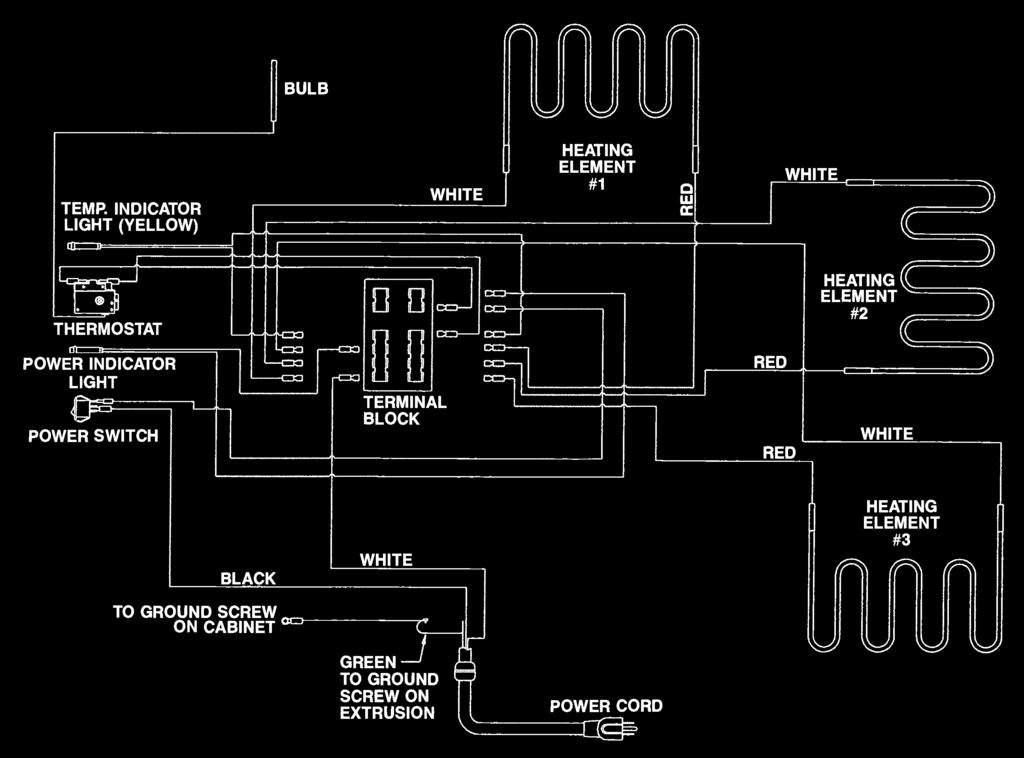
11 IV. Wiring Schematics 10
12 V. CLEANING INSTRUCTIONS ALL MODELS Your TC90 series cabinet has been listed by the National Sanitation Foundation (NSF) which means that it has been designed and constructed in a way that promotes a sanitary condition, i.e. sanitary materials and easy cleanability. To maintain a sanitary condition and obtain the best cabinet performance, Metro strongly suggests that the cabinet be thoroughly cleaned on an adequate regular basis daily if necessary. A. REMOVAL OF INTERIOR COMPONENTS FOR CLEANING All interior components are removable, without tools, for thorough, unobstructed cleaning. 1. CAUTION AT NO TIME SHOULD THE CABINET BE WASHED OR FLOODED WITH WATER OR LIQUID SOLUTION. NEVER STEAM CLEAN. SEVERE DAMAGE OR ELECTRICAL HAZARD COULD RESULT. 1. Turn off master switch. 2. Disconnect the unit from its power source. 2. WARNING ALLOW THE UNIT TO COOL BEFORE CLEANING, AS THE INTERIOR OF THE CABINET MAY BE HOT ENOUGH TO BURN. 3. If necessary, the door may be removed by simply lifting it from its cabinet-mounted hinges. Do not place the door against an object that may scratch the door or damage the gasket. 4. The slide racks may be removed by lifting them from their respective brackets. 5. After cleaning, simply reverse the above steps to reassemble the cabinet. B. SPECIFIC CLEANING INSTRUCTIONS 1. Do not immerse the cabinet when cleaning. Instead, use a damp cloth and a drying towel. BE SURE TO THOROUGHLY DRY THE UNIT BEFORE RETURNING IT TO USE. C. GENERAL CLEANING INSTRUCTIONS 1. LIGHT SOIL If routine (daily) cleaning is practiced, a mild soap and warm water should be sufficient to keep the unit clean. 2. HEAVIER SOIL If cleaning has been postponed, solvent or emulsion type cleaners that can be applied with bare hands will give excellent results. Such cleaners are available under various brand names and detergent suppliers can recommend materials appropriate for use on natural and epoxycoated aluminum and stainless steel interior liner. NOTE: For every cleaning method, best results are always obtained when the cleaner and technique are matched to the soil conditions involved. To ensure using the proper cleaner for natural and epoxy- coated aluminum and stainless steel, contact your detergent representative. VI. Maintenance A. CABINET MAINTENANCE ALL MODELS Your TC90 series cabinet has been designed to require very little maintenance. With normal use, cleaning is the only form of maintenance that need be done on a regular basis. Keeping the casters free of dirt build-up will go a long way in prolonging their life. If your cabinet is rolled over rough surfaces or transported over-the-road, the various threaded fasteners, i.e., screws and nuts, should be periodically inspected and tightened if necessary, particularly the transport latch, hinge and caster fasteners. B. CONTROL PANEL MAINTENANCE The control panel of your cabinet has also been designed to require very little maintenance. With normal use, cleaning is the only form of maintenance that need be done on a regular basis. No maintenance is required on the electrical components. 11
13 InterMetro Industries Corporation (hereinafter referred to as Seller ) warrants to the 12
14 Thank you for purchasing a Metro Mobile Heated Cabinet. We are certain you will be more than satisfied with its quality and performance. Please fill in the warranty information space below so we may register your warranty. Also, so that we may learn more about our customers and hopefully be of continued service in the future, please take a moment to fill in the customer information space below. Thank You Cut along dotted line CUSTOMER INFORMATION 1. Which one of the following best describes your establishment? a. Full Service Restaurant b. Fast Food Restaurant c. Hotel/Motel d. Hospital/Nursing Home e. College/University f. School g. Employee Feeding h. Other WARRANTY INFORMATION: Cabinet Model No. Module Serial No. Slide Rack Model No. Date Purchased Customer Name Address Phone No. For warranty coverage, this card must be returned to Metro. Cut along dotted line 2. Please indicate the two product benefits that were of major interest to you. a. Accessibility to controls without opening door. b. All components within cabinet removable for cleaning. c. Better control of conditions in cabinet. d. Aesthetic quality (styling). g. Other (in addition to above two) Fold Here Do not detach 3. Main factor that led to your decision to purchase this product? a. Product operating and functional features b. Overall quality c. Price d. Availability e. Other 4. Three sources that led to the purchase of this product in the order of their impact (1 - being most impact; 3 - being least impact). a. Trade Journal Ad b Trade Show c. Sales Call d. Direct Mail e. Previous Purchase f. Other 13
15 Fold Here Do not detach No postage necessary if mailed in the United States Business Reply Mail First-ClaSTAINLESS STEEL Permit No. 121 wilkes-barre, PA Postage Will Be Paid By INTERMETRO INDUSTRIES CORPORATION Attn: Customer Service P O Box A WILKES-Barre PA Staple Here Staple Here Staple Here
16 VII. SERVICE NOTES 15
17 VII. SERVICE NOTES 16
18 InterMetro Industries Corporation North Washington Street, Wilkes-Barre, PA For Product Information Call: Visit Our Web Site: L Rev. G 1/07 Information and specifications are subject to change without notice. Please confirm at time of order.
C5 4 SERIES INSULATION ARMOUR PLUS HOT FOOD HOLDING CABINETS
 INSTRUCTIONS FOR USE C5 4 SERIES INSULATION ARMOUR PLUS HOT FOOD HOLDING CABINETS TABLE OF CONTENTS Safety Information...2 Safety Symbols...2 Identify your Cabinet...2 Product Details...3 Installation
Metro Heated Banquet Cabinets
 Metro Heated Banquet Cabinets INSTRUCTIONS FOR USE This manual covers cabinets with electrical ratings of: 120V 1650W & 220V 1650W When ordering electrical parts, always confirm the rating listed on data
Metro Heated Banquet Cabinets
 Metro Heated Banquet Cabinets User Manual This manual covers cabinets with electrical ratings of: 120V 1650W & 220V 1650W. When ordering electrical parts, always confirm the rating listed on data plate
C5 4 SERIES INSULATION ARMOUR PLUS HOT OR COLD FOOD TRANSPORT CABINETS
 INSTRUCTIONS FOR USE C5 4 SERIES INSULATION ARMOUR PLUS HOT OR COLD FOOD TRANSPORT CABINETS TABLE OF CONTENTS Safety Information...2 Identify Your Cabinet...2 Product Details...3 Installation and Setup...3
C175 Series USER MANUAL FOR THE METRO C175 SERIES UNINSULATED HEATED CABINET. Recommended Food Holding Guidelines Listed on page 7. Rev.
 C175 Series Rev. 3/99 USER MANUAL FOR THE METRO C175 SERIES UNINSULATED HEATED CABINET Recommended Food Holding Guidelines Listed on page 7. InterMetro Industries Corporation Wilkes-Barre, PA 18705 570-825-2741
8 Series Controlled Temperature Heated Holding Cabinets
 8 Series Controlled Temperature Heated Holding Cabinets User Manual TM This manual covers cabinets with electrical ratings of: 120V 2000W, 120V 1440W & 220-240V 1681-2000W. When ordering electrical parts,
8 Series Controlled Temperature Heated Holding Cabinets
 8 Series Controlled Temperature Heated Holding Cabinets INSTRUCTIONS FOR USE TM This manual covers cabinets with electrical ratings of: 120V 2000W, 120V 1440W & 220-240V 1681-2000W. When ordering electrical
T-SERIES HOT FOOD HOLDING CABINETS INSTRUCTIONS FOR USE
 T-SERIES HOT FOOD HOLDING CABINETS INSTRUCTIONS FOR USE THIS MANUAL COVERS CABINETS WITH ELECTRICAL RATINGS OF: 120V 1400W & 220-240V 1176-1400W When ordering electrical parts, always confi rm the rating
CC-2222C-PL, CC-2222C-PRL, CC-2222C-PR-2, CC-2222C-PL-2,
 Rev. 14 (10/08) Page 1 of 16 INSTALLATION, OPERATION and MAINTENANCE MANUAL for Cres Cor Models: CC-2222C-PR, CC-2222C-PL, CC-2222C-PRL, CC-2222C-PR-2, CC-2222C-PL-2, and CC-2222C-PRL-2 Rev. 14 (10/08)
9 Series Controlled Humidity Heated Holding & Proofing Cabinets
 9 Series Controlled Humidity Heated Holding & Proofing Cabinets INSTRUCTIONS FOR USE This manual covers cabinets with electrical ratings of: 120V 2000W, 120V 1440W & 220-240V 1681-2000W. When ordering
OPERATING and MAINTENANCE INSTRUCTIONS Models: H138NPSCLCMCQRL Merchandising Hot Cabinets
 Rev. (/) Page of 0 OPERATING and MAINTENANCE INSTRUCTIONS Models: H8NPSCLCMCQRL Merchandising Hot Cabinets Cabinet model number: Cabinet serial number: Authorized Service Agency: Ph: Fax: Keep this manual
3 Series 1 Series Heated Cabinets
 Series 1 Series Heated Cabinets INSTRUCTIONS FOR USE TM Differences on voltage, amps or wattage are listed with bold text in replacement part descriptions. This manual covers both 120V and 220-240V cabinets,
Summer Breeze Heater Service Manual
 Summer Breeze Heater Service Manual RSBH RSBH-SB RSBHP Revision: 1.0 Issued: 12-18-2012 Table of Contents I. Basic Assembly and Operation A. Safety Instructions... 2 B. Grounding Instructions... 3 C.
OPERATING and MAINTENANCE INSTRUCTIONS Models: H138NPS36CLCMQRL i7 Hot Cabinet
 Rev. 0 (/) Page of 9 OPERATING and MAINTENANCE INSTRUCTIONS Models: HNPS6CLCMQRL i7 Hot Cabinet Cabinet model number: Cabinet serial number: Authorized Service Agency: Ph: Fax: Keep this manual for future
Wax Base Heater & Dispenser
 Wax Base Heater & Dispenser Service Manual Models: IDWB2/0900, IDWB2/0775, IDWB3/0900, IDWB3/0775, IDWB4/0900, IDWB4/0775 Introduction............................................................................
3 Series 1 Series Heated Cabinets
 Series Series Heated Cabinets INSTRUCTIONS FOR USE TM Differences on voltage, amps or wattage are listed with bold text in replacement part descriptions. This manual covers both 20V and 220-240V cabinets,
INSTALLATION and OPERATION INSTRUCTIONS
 INSTALLATION and OPERATION INSTRUCTIONS SINGLE DOOR freezer MODEL NOS. FN FS Finished Stainless Steel Top Non-Finished Top FS FN IMPORTANT INFORMATION This manual has been prepared to assist you in the
HOT FOOD HUMIDITY CABINET MODEL HFD-3
 Star Manufacturing International Inc. 10 Sunnen Drive St. Louis, MO 63143 Phone: (314) 781-2777 FAX: (314) 781-3636 Installation and Operating Instructions 2M-Y9774 Rev. E 2/12/97 HOT FOOD HUMIDITY CABINET
INSTALLATION INSTRUCTIONS ELECTRIC DRYER
 INSTALLATION INSTRUCTIONS ELECTRIC DRYER Table of Contents... 2 IMPORTANT: Save for local electrical inspector s use. 3397627C DRYER SAFETY... 2 INSTALLATION INSTRUCTIONS... 4 Tools and Parts... 4 Location
Viking Installation Guide
 Viking Installation Guide Viking Range Corporation 111 Front Street Greenwood, Mississippi 38930 USA (662) 455-1200 For product information, call 1-888-VIKING1 (845-4641) or visit the Viking Web site at
OPERATIONS MAINTENANCE MANUAL
 OPERATIONS MAINTENANCE MANUAL COOK & HOLD OVEN SYSTEMS WITTCO MODEL NUMBERS 1300-AD-SS 1300-AD-SS-SPLIT LIMITED WARRANTY Wittco warrants the Products that it manufactures to be free from defects in materials
MANUAL FOOD HOLDING & TRANSPORT CABINETS WITTCO MODEL NUMBERS
 O P E R A T I O N S M A I N T E N A N C E MANUAL FOOD HOLDING & TRANSPORT CABINETS WITTCO MODEL NUMBERS 1826-4 1826-7-BC-IS 1826-7 1826-13-BC-IS 1826-7-BC 1826-15-BC-IS 1826-13-BC 1826-15-BC 1826-40-BC
DAVIS PACKAGING. TD-362 Dual Roll Console Reference Guide.
 DAVIS PACKAGING www.davispackaging.net E-mail: contact@davispackaging.net TD-362 Dual Roll Console Reference Guide SPECIFICATIONS Overall Dimensions: Working Height: Power Requirement: Wattage: Unit Weight:
Installation Instructions
 Installation Instructions Before you begin... 2 Location... 2 Recommended grounding instructions... 2 Electrical requirements... 2 Exhaust requirements... 3 Water supply and drain requirements... 3 Please
Service Manual 26 Self Trimming Fireplace with 3 Stage Remote
 Service Manual 26 Self Trimming Fireplace with 3 Stage Remote Model Number: DF2690 MOD: 0 Dimplex North America Limited 1367 Industrial Road Cambridge ON Canada N1R 7G8 1-800-668-6663 www.dimplex.com REV
WARMING AND MERCHANDISING CABINET
 WARMING AND MERCHANDISING CABINET Above red graphics now replace green graphics shown in photo. MODEL 695 (Single door unit shown) MODEL 695-S (Single door unit shown) Snack foods have to be hot and moist
Questions on Installation? Call: 800.GE.CARES (US) WARNING RISK OF FIRE 4" DIA. METAL DUCT (RECOMMENDED) 4" DUCT CLAMPS (2) OR 4" SPRING CLAMPS (2)
 WARNING RISK OF FIRE 4 DIA. METAL DUCT (RECOMMENDED) 4 DUCT CLAMPS (2) OR 4 SPRING CLAMPS (2)") Installation Instructions Electric Dryer 01 Questions on Installation? Call: 800.GE.CARES (US) www.geappliances.com (US) PEDESTALS FOR DRYERS (comes with individual installation instructions) Three models
Installation Instructions Electric Dryer 01 Questions on Installation? Call: 800.GE.CARES (US) www.geappliances.com (US) PEDESTALS FOR DRYERS (comes with individual installation instructions) Three models
Installation Instructions. For the 18 Built-In Dishwasher and Front Color Panels
 Installation Instructions For the 18 Built-In Dishwasher and Front Color Panels Printed in USA 154232102 Before You Begin DO NOT INSTALL DISHWASHER UNTIL YOU HAVE READ ALL INSTRUCTIONS. FOR YOUR SAFETY,
INSTALLATION INSTRUCTIONS FOR 6532 SERIES PACKAGE HEAT PUMP
 INSTALLATION INSTRUCTIONS FOR 6532 SERIES PACKAGE HEAT PUMP RV Products A Division of Airxcel, Inc. P.O. Box 4020 Wichita, KS 67204 1976-360 (1-02) PP TABLE OF CONTENTS 1. Warnings......................................................
Service Manual. Model Number: DWOP20R. UL Part Number
 Service Manual Model Number: DWOP20R UL Part Number 6909030100 IMPORTANT SAFETY INFORMATION: Always read this manual first before attempting to service this fireplace. For your safety, always comply with
INSTALLATION and OPERATION INSTRUCTIONS
 INSTALLATION and OPERATION INSTRUCTIONS Single Door cooler series MODEL NOS. CS32SB CS32SG CS32SS CS32ST IMPORTANT INFORMATION To register your product, visit our web site at (www.perlick.com). Click on
Installation. 324 Series Built-In Dishwashers U L. Viking Range, LLC 111 Front Street Greenwood, Mississippi USA (662)
") Installation Viking Range, LLC Front Street Greenwood, Mississippi 890 USA (66) 455-00 For product information, call -888-845-464 or visit the Viking Website at vikingrange.com U L C U L 4 Series Built-In
Installation Viking Range, LLC Front Street Greenwood, Mississippi 890 USA (66) 455-00 For product information, call -888-845-464 or visit the Viking Website at vikingrange.com U L C U L 4 Series Built-In
RV Products Division INSTALLATION INSTRUCTIONS FOR SERIES HEAT PUMP INSTRUCTIONS D INSTALLATION DE LA POMPE À CHALEUR SÉRIE 47000
 RV Products Division INSTALLATION INSTRUCTIONS FOR 47000 SERIES HEAT PUMP INSTRUCTIONS D INSTALLATION DE LA POMPE À CHALEUR SÉRIE 47000 TABLE OF CONTENTS I. General Information..............................................
User s Manual and Operating Instructions
 User s Manual and Operating Instructions Model Numbers: PT-18W-DDF-A, PT-20F-DDF-A, PT-20S-DDF, PT-24O-DDF, PT-24-DDF, PT-24-DDF-F, PT-30-DDF, PT-30P-DDF-A, PT-30P-DDF-AF READ AND SAVE THESE INSTRUCTIONS
OPERATOR S MANUAL. BASIC PROJECT CENTERS Some instructions and drawings may not apply to your specific unit. SAFETY SERVICE PARTS CAPACITIES
 OPERATOR S MANUAL BASIC PROJECT CENTERS Some instructions and drawings may not apply to your specific unit. SERVICE PARTS LOCATING MODEL # INFORMATION Model number and other information required for service
INSTALLATION INSTRUCTIONS UNDERCOUNTER DISHWASHERS
 INSTALLATION INSTRUCTIONS UNDERCOUNTER DISHWASHERS VIKING 111 Front Street Greenwood, Mississippi 38930 USA (662) 455-1200 IMPORTANT - PLEASE READ AND FOLLOW Before beginning - please read these instructions
WARNING: ELECTRICAL GROUNDING INSTRUCTIONS
 BK AND BKT BLOWER ACCESSORY INSTALLATION INSTRUCTIONS Model BK Manually led Blower Model BKT Thermostatically led Blower WARNING: ELECTRICAL GROUNDING INSTRUCTIONS This appliance is equipped with a three-prong
29 IN. (73.7 CM) ELECTRIC DRYER INSTALLATION INSTRUCTIONS DRYER SAFETY
 ELECTRIC DRYER INSTALLATION INSTRUCTIONS DRYER SAFETY") 9 IN. (7.7 CM) ELECTRIC DRYER INSTALLATION INSTRUCTIONS DRYER SAFETY... INSTALLATION INSTRUCTIONS... Tools and Parts... Location Requirements... Electrical Requirements... Electrical Connection...4 Venting
9 IN. (7.7 CM) ELECTRIC DRYER INSTALLATION INSTRUCTIONS DRYER SAFETY... INSTALLATION INSTRUCTIONS... Tools and Parts... Location Requirements... Electrical Requirements... Electrical Connection...4 Venting
User Manual. Heater/Proofer Cabinets. Models: 177HEAT1836, 177HPI1812, 177HPI1836, 177HPU1812, 177HPU1836
 Heater/Proofer Cabinets Models: 177HEAT1836, 177HPI1812, 177HPI1836, 177HPU1812, 177HPU1836 Please read and keep these instructions. Indoor use only. 05/2017 www.avantcoequipment.com 1 Index General Information...4
V SERIES HDR GAS RANGES
 SERVICE MANUAL ONE POWERFUL PACKAGE V SERIES HDR GAS RANGES TOPS Open Top Hot Top Griddle Top Work Surface BASES Standard Oven Convection Oven Cabinet Base - NOTICE - This manual is prepared for use by
BK AND BKT BLOWER ACCESSORY INSTALLATION INSTRUCTIONS
 BK AND BKT BLOWER ACCESSORY INSTALLATION INSTRUCTIONS MODEL BK MANUALLY CONTROLLED BLOWER MODEL BKT THERMOSTATICALLY CONTROLLED BLOWER WARNING: ELECTRICAL GROUNDING INSTRUCTIONS This appliance is equipped
G-10s. Instruction Manual. G-Series Cooler UPRIGHT COOLER. Part No.11IPA
 G-Series Cooler UPRIGHT COOLER Part No.11IPA-062800 Instruction Manual FOR YOUR FUTURE REFERENCE Thank you for using our product. This manual will guide you in getting the best use of your cooler. Remember
SpeedClave Steam Sterilizers
 SpeedClave Steam Sterilizers Model Numbers: M7-020 thru -022 Serial Number Prefixes: V Service and Parts Manual "NO LONGER IN PRODUCTION" Some service parts may not be available for this product. FOR USE
IMPORTANT INFORMATION. Revised Dishwasher Installation Instructions
 IMPORTANT INFORMATION Revised Dishwasher Installation Instructions To obtain a revised copy of the entire Dishwasher User s Manual, go to www.eurotechappliances.com. SPECIAL EDITION 11-20-02 SAVE THESE
ELECTRIC DRYER INSTALLATION INSTRUCTIONS
 ELECTRIC DRYER INSTALLATION INSTRUCTIONS Table of Contents DRYER SAFETY... 2 INSTALLATION REQUIREMENTS... 3 Tools and Parts... 3 LOCATION REQUIREMENTS... 4 ELECTRICAL REQUIREMENTS... 6 INSTALL LEVELING
Operator s Manual CAYENNE HEAT N SERVE 4/3 RECTANGULAR RETHERMALIZER ENGLISH
 CAYENNE HEAT N SERVE 4/ RECTANGULAR RETHERMALIZER Item Description Voltage Watts Amps Plug 2050 T4R Countertop without Drain 120 1600 1. 5-15P 2051 TD4R Countertop with Drain 120 1600 1. 5-15P 2 T4R Countertop
Installation and User's Manual for Refrigerator Model SCR33
 Installation and for Refrigerator Model SCR33 Introduction Congratulations on your purchase of a Scotsman refrigeration product. For future reference, keep this guide in a safe, accessible location. If
WARMING AND MERCHANDISING CABINET
 WARMING AND MERCHANDISING CABINET MODEL 695 MODEL 695-S (Two door unit shown) (Single door unit shown) Snack foods have to be hot and moist to be appealing. Cold won t do... Dry won t do. Wisco s model
SS1095 Ice Maker.
 Installation Guide SS1095 Ice Maker www.u-lineservice.com Phone (414) 354-0300 FAX (414) 354-7905 Service & Parts Tech Lines Phone (800) 779-2547 FAX (414) 354-5696 OnlineService@U-Line.com 2008 U-Line
Concepts Serving Systems
 Concepts Serving Systems Installation Manual Please read this manual completely before attempting to install or operate this equipment! Notify carrier of damage! Inspect all components immediately. February
Water Distiller Service Manual
 Water Distiller Service Manual Water Distiller Service Manual L70478WT 2008 Regal Ware, Inc. Table of Contents RECOMMENDED TOOLS... 2 GENERAL INSPECTION...3 BOILING CHAMBER TROUBLESHOOTING & REPAIRS Description...
Service Manual 26 Self Trimming Export Fireplace with 3 Stage On/Off Remote
 Service Manual 26 Self Trimming Export Fireplace with 3 Stage On/Off Remote Model Numbers: DF2608-EU - MOD / to A DF2608-AU - MOD / Dimplex North America Limited 1367 Industrial Road Cambridge ON Canada
E32 CONVECTION OVEN SERVICE MANUAL -1- Revision 1/F3508
 E32 CONVECTION OVEN SERVICE MANUAL -1- WARNING: ALL INSTALLATION AND SERVICE REPAIR WORK MUST BE CARRIED OUT BY QUALIFIED PERSONS ONLY. -2- CONTENTS This manual is designed to take a more in depth look
WAILEA OWNER S MANUAL
 WAILEA OWNER S MANUAL The blades in each pack are matched for equal weight to assure smooth fan operation. If more than one fan is being installed, be careful not to mix blades from different cartons.
User s Manual and Operating Instructions
 User s Manual and Operating Instructions Model Numbers: CL-30P-DDF, CL-20F-DDF, CL-24O-DDF, CL-30-DDF READ AND SAVE THESE INSTRUCTIONS IMPORTANT: Read and understand all of the directions in this manual
UNIVERSAL 750 PRE-MIX DISPENSER
 Anoka, MN. 0 - Telephone -00--00 Facsimile -00--0 MODEL NO. xxx xxx Universal 0 of Control Code A Manual Part No. 00 -- Revised: -- ªIMI Cornelius Co., - Anoka, MN. 0 - Telephone -00--00 Facsimile -00--0
Installation Electric Dryers Instructions 01
 Installation Electric Dryers Instructions 01 Questions? Call 800.GE.CARES (800.432.2737) or visit our Web site at: GEAppliances.com This is the safety alert symbol. This symbol alerts you to potential
INSTALLATION INSTRUCTIONS FOR 6636 SERIES PACKAGE AIR CONDITIONER
 INSTALLATION INSTRUCTIONS FOR 6636 SERIES PACKAGE AIR CONDITIONER TABLE OF CONTENTS 1. Warnings...................................................... 3 2. Component Match-Up...........................................
concessionstands.com
 WARNING!! The attached Gold Medal Manual is for reference only and is not intended for any other purpose. The information contained in these on line manuals is subject to change at any time. Improvements
INSTALLATION, OPERATION and MAINTENANCE MANUAL for Cres Cor AQUATEMP TM HUMIDITY CONVECTION and RETHERM OVENS with MICROPROCESSOR CONTROLS
 9 Heisley Road Mentor, OH 0- Rev. (6/0) Page of INSTALLATION, OPERATION and MAINTENANCE MANUAL for Cres Cor AQUATEMP TM HUMIDITY CONVECTION and RETHERM OVENS with MICROPROCESSOR CONTROLS ROFWB-Q COFWUAB-Q
ELECTRIC DRYER INSTALLATION INSTRUCTIONS
 ELECTRIC DRYER INSTALLATION INSTRUCTIONS Table of Contents DRYER SAFETY... 2 INSTALLATION REQUIREMENTS... 3 Tools and Parts... 3 LOCATION REQUIREMENTS... 4 ELECTRICAL REQUIREMENTS... 5 INSTALL LEVELING
INSTALLATION INSTRUCTIONS FOR SERIES TWO TON HIGH EFFICIENCY PACKAGED HEAT PUMP
 RV Products Division INSTALLATION INSTRUCTIONS FOR 46515 SERIES TWO TON HIGH EFFICIENCY PACKAGED HEAT PUMP TABLE OF CONTENTS 1. Warnings.................................................. 2 2. Component
WARNING. Tighten strain relief screws to secure cable. Make sure screw heads are facing up when tightening conduit nut.
 WARNING Electrical Shock Hazard Electrically ground dishwasher. Connect ground wire to green ground connector in terminal box. Do not use an extension cord. Failure to follow these instructions can result
G-7s. Instruction Manual. G-Series Cooler COUNTERTOP COOLER. Part No.11IPA
 G-Series Cooler COUNTERTOP COOLER Part No.11IPA-061000 Instruction Manual FOR YOUR FUTURE REFERENCE This easy-to-use manual will guide you in getting the best use of your cooler. Remember to record the
Installing the Cisco ONS FAP-4 Fuse Alarm Panel
 Installing the Cisco ONS 15454-FAP-4 Fuse Alarm Panel Product Number: 15454-FAP-4= This document explains how to install, test, operate, and maintain the Cisco ONS 15454-FAP-4 fuse alarm panel. This document
OPERATIONS FOOD HOLDING & TRANSPORT CABINETS. wîttco foodservice. equipment
 OPERATIONS MAINTENANCE MANUAL FOOD HOLDING & TRANSPORT CABINETS WITTCO MODEL NUMBERS 1220-105-2-BC 1220-105-3-BC 1220-105-4-BC A A wîttco foodservice equipment F-41009 LIMITED WARRANTY Wittco warrants
Built-In Dishwasher. Installation Instructions. BEFORE YOU BEGIN Read these instructions completely and carefully. IMPORTANT The dishwasher MUST be
 Installation Instructions Built-In Dishwasher If you have questions, call 800.GE.CARES (800.432.2737) or visit our website at: www.ge.com BEFORE YOU BEGIN Read these instructions completely and carefully.
Instruction Manual. Dogeroo, Super Dogeroo, and Mini Dogeroo
 Instruction Manual Dogeroo, Super Dogeroo, and Mini Dogeroo Model No. 8102, 8103, 8108 10700 Medallion Drive, Cincinnati, Ohio 45241-4807 USA Part No. 87793 SAFETY PRECAUTIONS Page 2 INSTALLATION INSTRUCTIONS
Installation Instructions
 4 3 Installation Instructions Self Cleaning Free-Standing Electric Range EER2000, EER3000, EER3001, EER3002, JBP10, JBP24, JBP26, JBP30, JBP35, JBP48, JBP64, JBP66, JBP68, JBP69, JBP71, JBP78, JBP80, JBP82,
Manual Examination Table
 Manual Examination Table 204 204 604 Model Numbers: -001 thru -007-011 thru -014-001 thru -006 Service and Parts Manual 604 shown FOR USE BY MIDMARK TRAINED TECHNICIANS ONLY SF-1864 Part No. 004-0483-00
6 Oz. Twin Pop. Popcorn Machine Instruction Manual Model #2666EX. Cincinnati, OH USA. Part No EX Revised June 1996
 Popcorn Machine Instruction Manual Model #2666EX Part No. 16169EX Revised June 1996 Cincinnati, OH 45214-2089 USA SAFETY PRECAUTIONS This equipment is designed and sold for commercial use only. This equipment
 Installation Guide BI-98 Ice Maker www.u-lineservice.com Phone (414) 354-0300 FAX (414) 354-7905 Service & Parts Tech Lines Phone (800) 779-2547 FAX (414) 354-5696 OnlineService@U-Line.com 2005 U-Line
PARTS AND SERVICE MANUAL FOR THE 23 COMPACT FIREPLACE
 PARTS AND SERVICE MANUAL FOR THE 23 COMPACT FIREPLACE TABLE OF CONTENTS OPERATION PAGE 1 PARTS DRAWING PAGE 3 PARTS LIST PAGE 4 LIGHT BULB REPLACEMENT PAGE 5 HEATER ON/OFF SWITCH REPLACEMENT PAGE 6 THERMOSTAT
MODEL 925W FEATURES: ELECTRICAL DATA: DIMENSIONS: SHIPPING INFORMATION: FOOD WARMING/ MERCHANDISING CABINET
 FOOD WARMING/ MERCHANDISING CABINET MODEL 925W This warmer/merchandiser provides heated circulating air to keep foods fresh and evenly warmed. It is constructed of stainless steel and tempered glass for
E32 CONVECTION OVEN SERVICE MANUAL
 E32 CONVECTION OVEN SERVICE MANUAL Applies to units from S/N 40256-1- WARNING: ALL INSTALLATION AND SERVICE REPAIR WORK MUST BE CARRIED OUT BY QUALIFIED PERSONS ONLY. -2- CONTENTS This manual is designed
OPERATING and MAINTENANCE INSTRUCTIONS Taco Bell Hot Cabinet Full Size Model: H137S27D1TB & H137S27D1LTB Half Size Model: H137S273D1TB & H137S273D1LTB
 Rev. 1 (6/15) Page 1 of 5 Taco Bell Full Size Model: & H137S27D1LTB Half Size Model: & H137S273D1LTB H137S27D1LTB H137S273D1LTB Cabinet model number: Cabinet serial number: Authorized Service Agency: Ph:
CABINET PARTS. For Models: GD2SHAXNQ00, GD2SHAXNT00, GD2SHAXNB00, GD2SHAXNS00, GD2SHAXNL00 (White) (Biscuit) (Black) (Stainless Steel) (Stainless VCM)
 (Biscuit) (Black) (Stainless Steel) (Stainless VCM)") CABINET PARTS REFRIGERATOR 5 04 Litho In U.S.A. (kdj) 1 Part No. Rev. A CABINET PARTS 1 Literature Parts 2261717 Use & Care Guide 2255955 Service & Wiring Sheet 2305881 Energy Guide 2220407 Modular Icemaker
CABINET PARTS REFRIGERATOR 5 04 Litho In U.S.A. (kdj) 1 Part No. Rev. A CABINET PARTS 1 Literature Parts 2261717 Use & Care Guide 2255955 Service & Wiring Sheet 2305881 Energy Guide 2220407 Modular Icemaker
INSTALLATION, OPERATION and MAINTENANCE MANUAL for Cres Cor RADIANT OVENS
 FL--D 595 Heisley Road Mentor, OH 440-8 Rev. 0 (5/) Page of INSTALLATION, OPERATION and MAINTENANCE MANUAL for Cres Cor RADIANT OVENS 000-CH-SS-D 000-CH-AL-D 000-CH-SS-SPLIT-D 000-CH-AL-SPLIT-D 000-CH-SS-SPLIT-D0
RCM-77. Instruction Manual. G-Series Cooler. U.S. Patent No. 8,215,125 RECHARGE COLD MERCHANDISER
 G-Series Cooler RECHARGE COLD MERCHANDISER U.S. Patent No. 8,215,125 Instruction Manual FOR YOUR FUTURE REFERENCE This easy-to-use manual will guide you in getting the best use of your cooler. Remember
SERVICE MANUAL. Bradford White ElectriFLEX HD (Heavy Duty) Commercial Electric Water Heater CEHD SERIES Immersion Thermostat Models
 Commercial Electric Water Heater CEHD SERIES Immersion Thermostat Models") Bradford White ElectriFLEX HD (Heavy Duty) Commercial Electric Water Heater CEHD SERIES Immersion Thermostat Models SERVICE MANUAL Troubleshooting Guide and Instructions for Service (To be performed ONLY
Bradford White ElectriFLEX HD (Heavy Duty) Commercial Electric Water Heater CEHD SERIES Immersion Thermostat Models SERVICE MANUAL Troubleshooting Guide and Instructions for Service (To be performed ONLY
Installation Instructions
 Installation Instructions Built-In Dishwasher If you have questions, call 800-944-9400(US),800-245-8352(Canada)or visit our website at: www.frigidaire.com BEFORE YOU BEGIN Read these instructions completely
Service Manual. Model Number: Compact Fireplace DF203A DF2006. UL Part Number to 800
 Service Manual Model Number: Compact Fireplace DF203A DF2006 UL Part Number 6901860100 to 800 IMPORTANT SAFETY INFORMATION: Always read this manual first before attempting to service this fireplace. For
DIRECT DRAW BEER COOLERS Installation, Operation and Maintenance Instructions
 DIRECT DRAW BEER COOLERS Installation, Operation and Maintenance Instructions INSPECTION When the equipment is received, all items should be carefully checked against the Bill of Lading to ensure all crates
FOOD WARMING/MERCHANDISING CABINET
 FOOD WARMING/MERCHANDISING CABINET MODEL 323HH (15 ) & 323HH-7 (7 ) (*Above photo shows a 15 & 7 model side by side) With the ability to hold a point-of-purchase advertisement, these sleek, compact warmers
Service. Manual. Built-in Dishwasher. Preferred Service. VDB450 DFB450 (Before 5/26/2010)
") Service Preferred Service Manual This manual is to be used by qualified appliance technicians only. Viking does not assume any responsibility for property damage or personal injury for improper service
Service Preferred Service Manual This manual is to be used by qualified appliance technicians only. Viking does not assume any responsibility for property damage or personal injury for improper service
INSTALLATION. Glass Panel Doors (select models) CAUTION
 CAUTION") Location Do not install refrigerator near oven, radiator or other heat source. If not possible, shield refrigerator with cabinet material. Do not install where temperature falls below 55 F (13 C) or rises
Location Do not install refrigerator near oven, radiator or other heat source. If not possible, shield refrigerator with cabinet material. Do not install where temperature falls below 55 F (13 C) or rises
OPERATING INSTRUCTIONS
 OPERATING INSTRUCTIONS TOP MOUNT HEATED HOLDING Heated Holding Food Warmers With Dial Face Controls or HDM Controls FWE TOP MOUNT HEAT SYSTEM FWE Heated Holding Cabinets Keep your food oven fresh longer!
CABINET PARTS For Models: GS6SHAXKQ01, GS6SHAXKT01, GS6SHAXKB01, GS6SHAXKS01 (White) (Biscuit) (Black) (Stainless Steel)
 (Biscuit) (Black) (Stainless Steel)") CABINET PARTS REFRIGERATOR 3 01 Printed In U.S.A. (mdg) 1 Part No. CABINET PARTS LITERATURE PARTS 1 LIT2216812 Energy Guide LIT2205958 Owner s Manual LIT2216656 Service & Wiring Sheet LIT628370 Modular
CABINET PARTS REFRIGERATOR 3 01 Printed In U.S.A. (mdg) 1 Part No. CABINET PARTS LITERATURE PARTS 1 LIT2216812 Energy Guide LIT2205958 Owner s Manual LIT2216656 Service & Wiring Sheet LIT628370 Modular
ELECTRIC DRYER INSTALLATION INSTRUCTIONS
 ELECTRIC DRYER INSTALLATION INSTRUCTIONS Para una version de estas instrucciones en español, visite www.whirlpool.com Table of Contents DRYER SAFETY... 2 Installation Requirements... 3 Tools and Parts...
FOOD WARMING/MERCHANDISING CABINET MODEL 737/737HH
 FOOD WARMING/MERCHANDISING CABINET MODEL 737/737HH This unique compact warmer utilizes heated, circulating air to maintain food at proper temperatures for extended periods of time. It has the capability
CABINET PARTS REFRIGERATOR. For Models: GD2SHAXKQ03, GD2SHAXKT03, GD2SHAXKB03 (White) (Biscuit) (Black) 5 02 Litho In U.S.A. (mek) 1. Part No.
 (Biscuit) (Black) 5 02 Litho In U.S.A. (mek) 1. Part No.") CABINET PARTS REFRIGERATOR 5 02 Litho In U.S.A. (mek) 1 Part No. CABINET PARTS 1 LITERATURE PARTS LIT2220699 Use & Care Guide LIT2220104 Service & Wiring Sheet LIT2220300 Energy Guide LIT2220407 Modular
CABINET PARTS REFRIGERATOR 5 02 Litho In U.S.A. (mek) 1 Part No. CABINET PARTS 1 LITERATURE PARTS LIT2220699 Use & Care Guide LIT2220104 Service & Wiring Sheet LIT2220300 Energy Guide LIT2220407 Modular
INSTALLATION INSTRUCTIONS FOR 6536 SERIES TWO TON PACKAGED HEAT PUMP
 INSTALLATION INSTRUCTIONS FOR 6536 SERIES TWO TON PACKAGED HEAT PUMP TABLE OF CONTENTS 1. Warnings...2 2. Component Match-Up...2 3. Unit Depiction Figures...3 4. Blower Performance Data...5 5. General
CABINET PARTS. For Models: GS5SHAXNQ02, GS5SHAXNT02, GS5SHAXNB02, GS5SHAXNS02, GS5SHAXNL02 (White) (Biscuit) (Black) (Stainless Steel) (Stainless VCM)
 (Biscuit) (Black) (Stainless Steel) (Stainless VCM)") CABINET PARTS REFRIGERATOR 10 05 Printed In U.S.A. (kdr) 1 Part No. CABINET PARTS 1 Literature Parts 2305895 Energy Guide 2315213 Owner s Manual 2255955 Service & Wiring Sheet 2220407 Modular Icemaker
CABINET PARTS REFRIGERATOR 10 05 Printed In U.S.A. (kdr) 1 Part No. CABINET PARTS 1 Literature Parts 2305895 Energy Guide 2315213 Owner s Manual 2255955 Service & Wiring Sheet 2220407 Modular Icemaker
2 PREPARE THE OPENING
 Installation Instructions 27 & 30 Electric Built-In Wall Ovens Questions? Call 1.800.GE.CARES (1.800.432.2737) or visit www.geappliances.com In Canada, call 1.800.561.3344 or visit www.geappliances.ca
1217A Operating Instructions
 1217A Operating Instructions Reversible Motor Friction Fed Conveyor Stacker Easy Disassembly Adjustable Folds Counter Available MADE IN USA SPECIFICATIONS Paper Weight.28 Lbs. Bond, 90Lbs. Cover, 135Lbs.
DRYER INSTALLATION INSTRUCTIONS
 DRYER INSTALLATION INSTRUCTIONS Table of Contents DRYER SAFETY... 1 INSTALLATION REQUIREMENTS... 2 Tools and Parts... 2 Location Requirements... 3 Electrical Requirements... 5 INSTALLATION INSTRUCTIONS...
Service Manual. Model Number VCX1525 VCX1525-WH. UL Part Number
 Service Manual Model Number VCX1525 VCX1525-WH UL Part Number 6904000100 IMPORTANT SAFETY INFORMATION: Always read this manual first before attempting to service this fireplace. For your safety, always
Installation Instructions 30 French Door Built-in Wall Ovens
 Installation Instructions 30 French Door Built-in Wall Ovens Questions? Call 1.800.GE.CARES (1.800.432.2737) or visit www.geappliances.com In Canada, call 1.800.561.3344 or visit www.geappliances.ca DESIGN
PIASECKI AIRCRAFT CORPORATION TECHNICAL MANUAL OVERHAUL WITH PARTS BREAKDOWN AIRCRAFT OVEN - P/N X-006 Rev: B
 PIASECKI AIRCRAFT CORPORATION TECHNICAL MANUAL OVERHAUL WITH PARTS BREAKDOWN AIRCRAFT OVEN - 50-X-006 Rev: B Title/Subject: Technical Manual for Aircraft Oven FSN: 7310-905-6212 T.O.: Date: Written By:
CABINET PARTS For Model: ED5GTGXNQ14, ED5GTGXNB14 (White) (Black)
 (Black)") CABINET PARTS REFRIGERATOR 07 07 Litho In U.S.A. (mat) 1 Part No. Rev. A CABINET PARTS 1 Literature Parts 2315254 Use & Care Guide 2255373 Service & Wiring Sheet 2318639 Energy Guide 628370 Modular Icemaker
CABINET PARTS REFRIGERATOR 07 07 Litho In U.S.A. (mat) 1 Part No. Rev. A CABINET PARTS 1 Literature Parts 2315254 Use & Care Guide 2255373 Service & Wiring Sheet 2318639 Energy Guide 628370 Modular Icemaker