A GUIDE TO PASSING THE PLUMBING EXAM
|
|
|
- Cornelius Ray
- 5 years ago
- Views:
Transcription

1 A GUIDE TO PASSING THE PLUMBING EXAM BASED ON THE INTERNATIONAL PLUMBING AND FUEL GAS CODES WRITTEN BY JOHN WHITE REVISED This manual is the sole property of Energy Marketing Services. No part of this manual may be reproduced in any form or by any means without express written permission by the owner. ENERGY MARKETING SERVICES
2 ABOUT THIS GUIDE This guide has been designed as an aid for students preparing to take the Plumbing Exam based on the International Plumbing and Fuel Gas Codes, hereinafter referred to as the IPC or IFGC in this guide. It is not intended to replace any code books, manuals, or material required for study. Preparing a study guide for the IPC is a challenging event, as many states and jurisdictions that have adopted the IPC have added their own amendments. For example, the IPC states the building drain ends 30 inches outside the foundation wall. Some states, however, have amended this to 5 or 10 feet. Some tables in this guide have had footnotes added. In some instances, entire sections have been added or deleted. Therefore, our section numbers may not correspond to those in your state s IPC; however, they should be close. If any information in this guide disagrees with your state s IPC, then accept your code as the final authority. The student must obtain the following reference material in order to use this guide: International (or your state) Plumbing Code International (or your state) Fuel Gas Code* Note: If the plumbing license you plan to obtain does not allow for gas piping or gas appliance installation, you will not need the Fuel Gas Code and you may skip the Fuel Gas section of this guide.
3 TABLE OF CONTENTS ABOUT THIS GUIDE...2 INTERNATIONAL PLUMBING EXAM PREP COURSE...4 ADMINISTRATION...6 DEFINITIONS...7 GENERAL REGULATIONS...21 INTERNATIONAL ACCESSIBILITY CODE...25 WATER HEATERS...27 WATER SUPPLY AND DISTRIBUTION...28 SANITARY DRAINAGE...39 INDIRECT AND SPECIAL WASTE...47 VENTS...48 ISOMETRICS...51 TRAPS, INTERCEPTORS, AND SEPARATORS...61 STORM DRAINAGE...62 INTERNATIONAL PRIVATE SEWAGE DISPOSAL CODE...64 SOIL ABSORPTION SYSTEMS...65 TANKS...66 INTERNATIONAL FUEL GAS CODE...67 CONTRACTING BUSINESS...72 PRACTICE PLUMBING QUESTIONS...83
4 Introduction International Plumbing Exam Prep Course No course or standard classroom course is able to read the IPC for you. It is important that you read through the IPC to at least become familiar with its content. You are not expected to commit every word to memory. That is why the exam is open book. You don t have to remember that horizontally installed PVC pipe must be supported every four feet, but you should at the very least know there is a code requirement and approximately where to find it in the book. As you read through each code chapter of the IPC, refer to the corresponding chapter in this guide. If you should have difficulty understanding a code section of the IPC, there is a good chance this guide has a good explanation for you. This guide includes an appendix that contains 150 questions. Answering these questions will give you a clear and comprehensive grasp of the IPC. An extensive effort has been made to present accurate information in this third edition. Should you have questions or comments please feel free to contact us by at jrwmtw@gotricounty.com Highlighting Highlighting is a useful aid for finding and identifying important items throughout the IPC. Too much highlighting, however, will negate all your efforts. The trick is to highlight the least number of words and still catch the main idea. For example, look at Section 2 of Chapter 3. The entire section discusses tests and inspections. Section mentions required tests. It should be obvious that plumbing must be tested. What s important is the sentence in the middle of the paragraph: All plumbing system piping must be tested with either water or air. This is the only sentence that should be highlighted in the paragraph Test gauges. Gauges used for testing shall be as follows: 1) Tests requiring pressures of 10 pounds per square inch (PSI) or less shall utilize a testing gauge having increments of 0.01 PSI or less. 2) 2) Test requiring a pressure greater than 10 PSI but less than or equal to 100 PSI shall utilize a testing gauge having increments of 1 PSI or less.
5 Introduction 5 3) Tests requiring a pressure greater than 100 PSI shall utilize a testing gauge having increments of 2 PSI or less. The following paragraph is Section of the IPC and titled Drainage and vent water test. What s important in this paragraph? First, it s talking about drainage and vent water testing (not water supply piping or air testing). So highlight Drainage and vent water test. The center of the paragraph explains the pressure needed. Highlight 10-foot. The end of the paragraph explains how long. Highlight 15 minutes. Get the idea? If you were to highlight the entire paragraph or sentence the important details would not stand out.
6 Chapter 1 Administration Section 101 This Chapter is brief and easy to understand. Read and highlight the Scope and Intent or Purpose.

7 Chapter 2 Definitions Many of the answers to questions on the Plumbing Exam will come from this chapter. The following is an example of such a question. Question: A room containing a water closet, lavatory and bathtub is a. a. bath room b. toilet room c. toilet d. all of the above Answer: After reading through the three definitions, you should recognize a as the correct answer. You should read and understand all the definitions. Below are the definitions that people tend to misunderstand the most. Air admittance valve Air break Same as a studor vent. A vent that allows air to enter the vent pipe only in the direction toward the sewer. Air space is below the flood level rim The space between the standpipe and the washer hose is an air break
8 Definitions 8 Air gap (water system) flood level commercial sink commercial sink air gap (drainage) floor drain Air gap (drainage) air space is above flood level of receptacle Base flood elevation = 100 year flood level Building drain Extends 30 inches beyond building wall (Note: some states have amended this distance to as much as 10 feet, check the definition in your code book) Building sewer-pipe between building drain and street IPC states building drain extends 30 beyond foundation walls. Some states have extended this distance to up to 10 feet. Check your code book. building drain building sewer
9 Definitions 9 Circuit vent A vent connected to a horizontal drainage branch that serves at least two traps (max eight). Connects to the horizontal branch drain just before (downstream), the last fixture trap. Circuit Vent Combination fixture A single fixture comprised of two or more fixtures, such as a three compartment sink. Developed length of vents There are two definitions of developed length for vents: Fixture branch The developed length of a stack vent or vent stack is measured from the vent connection at the drain to the open air. The developed length of other vents (ie. individual vent) is the measured length from its point of connection to the drainage system to its point of connection to a venting stack or outside termination. (The developed length of the circuit vent above is the distance measured from the point of connection at the horizontal drain to the point of connection to the main vent.) Drain must have at least two fixtures to be called a branch. Grease interceptor Grease trap Handles more than 50GPM, outside of building (2006 code) Handles less than 50 GPM (2006 code). Note: 2009 IPC has done away with the term grease trap. All grease receptacles are referred to as grease interceptors.
10 Definitions 10 Horizontal pipe Hot water Less than 45 degrees off the horizon. Go to vertical pipe definition now. Water that is 110 degrees or greater. Note: Water with a temperature greater than 140 degrees must discharge into an indirect waste receptor before entering the drainage system. (803.1). sink indirect waste pipe floor sink Air gap to be minimum twice the effective opening of the indirect waste pipe Indirect waste receptor May be floor sink, mop receptor, service sink and standpipe with air gap. Lead-free pipe and fittings Contains 8% or less lead. Lead-free solder and flux. Contains.2% or less lead. (Notice the.) Plumbing appurtenance An item that does not consume water. Plumbing appurtenances include instruments, gauges, relief valves, limit switches, backflow assemblies, solenoid valves, and devices between solenoid valves. Plumbing fixture An item that consumes water. Examples include sinks, tubs, and water closets. Plumbing system According to IPC includes the storm sewer. Sanitary sewer Carries sewage, not storm water.
11 Definitions 11 Slope Stack vent A pipe with a 1/4-inch per foot slope is also described as having 4 units vertical and 12 units horizontal. A 1/4-inch per foot drop produces a drop of one inch for each 4-foot length, likewise, and 1/8-inch drop produces a drop of one inch for each 8-foot length of pipe. To determine the drop of a pipe in inches, divide the length (feet) by the lower number of the slope. Example: A 75 ft. pipe requiring a ¼-inch slope would have a drop of inches (75/4 = 18.75). A vent attached to a soil (main) stack. Typical residential drain and vent system
12 Definitions 12 Swimming pool A construction that must have at least a 2-foot depth. Tempered water Vent stack Water that is degrees. A separate stack that serves as only a vent for a drain pipe. A vent stack is always dry. See illustration above. Vertical pipe A pipe that is 45 degrees or greater. Is a pipe that makes an angle of 45 degrees with the horizontal a vertical or horizontal pipe? Answer: vertical (carefully read definition of both). Water pipe (types) Riser Pipes that extend upward one story or greater. Water distribution pipe-piping inside of a building. Water service pipe-water pipe that is located outside of a building (see Section to determine the point of termination).
13 Definitions 13 Yoke vent See illustrations below and Sections 914 and 915 (if available in your IPC book). main vent stack SECTION 914 Must be connected at least 3 ft. above floor Only place an inverted wye is allowed. 10th branch interval from top floor Yoke vent used as relief vent (must be same size as vent)
14 Definitions 14 SECTION 915 Offset with five or more branch intervals above Yoke vent. Located between offset and next lower horizontal branch main vent stack drainage stack
15 Definitions 15 Plumbing math and other interesting stuff Quarter bend, eighth bend, sixteenth bend 1/4 bend = 90 degree turn 1/8 bend = 45 degree turn 1/16 bend = 22.5 degree turn How many eighth bends are needed to make a 45 degree turn? Answer: 1 How many sixteenth bends are required to make a 45 degree turn? Answer: 2 (45 degrees/ 22.5 degrees = 2) Facts about water: Boils at 212 degrees F or 100 degrees C Freezes at 32 degrees F or 0 degrees C It takes 1 btu to raise the temperature of 1 lb of water 1 degree F (btu = 1 x lbs x temp. rise) Weighs 8.33 lbs/gal. or 64 lbs per cubic ft. Exerts a pressure of.433 lbs / ft. of elevation How many btu's are required to raise 40 gals of water 60 degrees F? Answer: Use formula, btu = 1 x lbs x temp rise First, convert 40 gals. to lbs. (40 x 8.33 = lbs.) Second, apply formula 1 x x 60 = 19,992 btu's How many psi are required to raise a column of water 30 ft. Answer: 30 x.433 = psi
16 Definitions 16 If the water pressure entering a home is 45 psi, what would be the pressure at a third floor fixture located 27 ft above the entrance point. Answer: First, determine the pressure required to elevate the water 27 feet 27 x.433 = psi pressure loss Second, subtract the pressure loss from the entering pressure. Calculating the volume of vessels and pipes = psi remains for the third floor fixtures Many times you may need to know the amount of water (gallons) a vessel will hold or the weight of a filled vessel or pipe to determine the amount of support needed. Volume = length x width x height = 62" x 24" x 36" = 53,568 cubic inches Convert to cubic feet 1 cubic foot = 1728 cubic inches 53,568/1728 = 31 cubic feet Volume = area x height First, calculate area of circle Area of circle = πr 2 π = 3.14, R =.5 x diameter =.5 x 36" = 18" Area = 3.14 x (18" x 18") = 3.14 x 324 = 1017 sq. inches Volume 1017 x 12 = 12,204 cubic inches Convert to cubic ft. 12,204/1728* = 7.06 cu.ft. *1 cubic ft. = 1728 cubic in. (12 x 12 x12) Convert to weight 7.06 cu ft x 64 = lbs Convert to gallons 451.8/8.33 = 54.2 gals
 Area of circle = πr 2 40' x 4 riser = 3.14 x (2 x 2) = 3.14 x 4 = 12.56 sq. in. Second, calculate the volume Volume = area x length = 12.56 sq. in. x 480 in*.")
17 Definitions 17 Pipe Calculate the volume of a pipe just like that of a cylinder above. Volume = area x length If the pipe is 4"' diameter x 40 ft. long First, calculate area of circle (pipe opening) Area of circle = πr 2 40' x 4 riser = 3.14 x (2 x 2) = 3.14 x 4 = sq. in. Second, calculate the volume Volume = area x length = sq. in. x 480 in*. = cubic inches * 40 ft must to be converted to inches (40 x 12) The pipe will hold 3.49 cubic feet of water cu. ft./1728 cu. in. = 3.49 The weight of the water will be 223 lbs cu. ft. x 64 lbs = 223 Calculate length of a 45 degree offset pipe = Run or rise X X fitting allowance Assume a fitting allowance of 1.5 inches (obtained from manufacturers specs) 40 X (2 x 1.5 ) run rise 1. fitting allowan X
18 Definitions 18

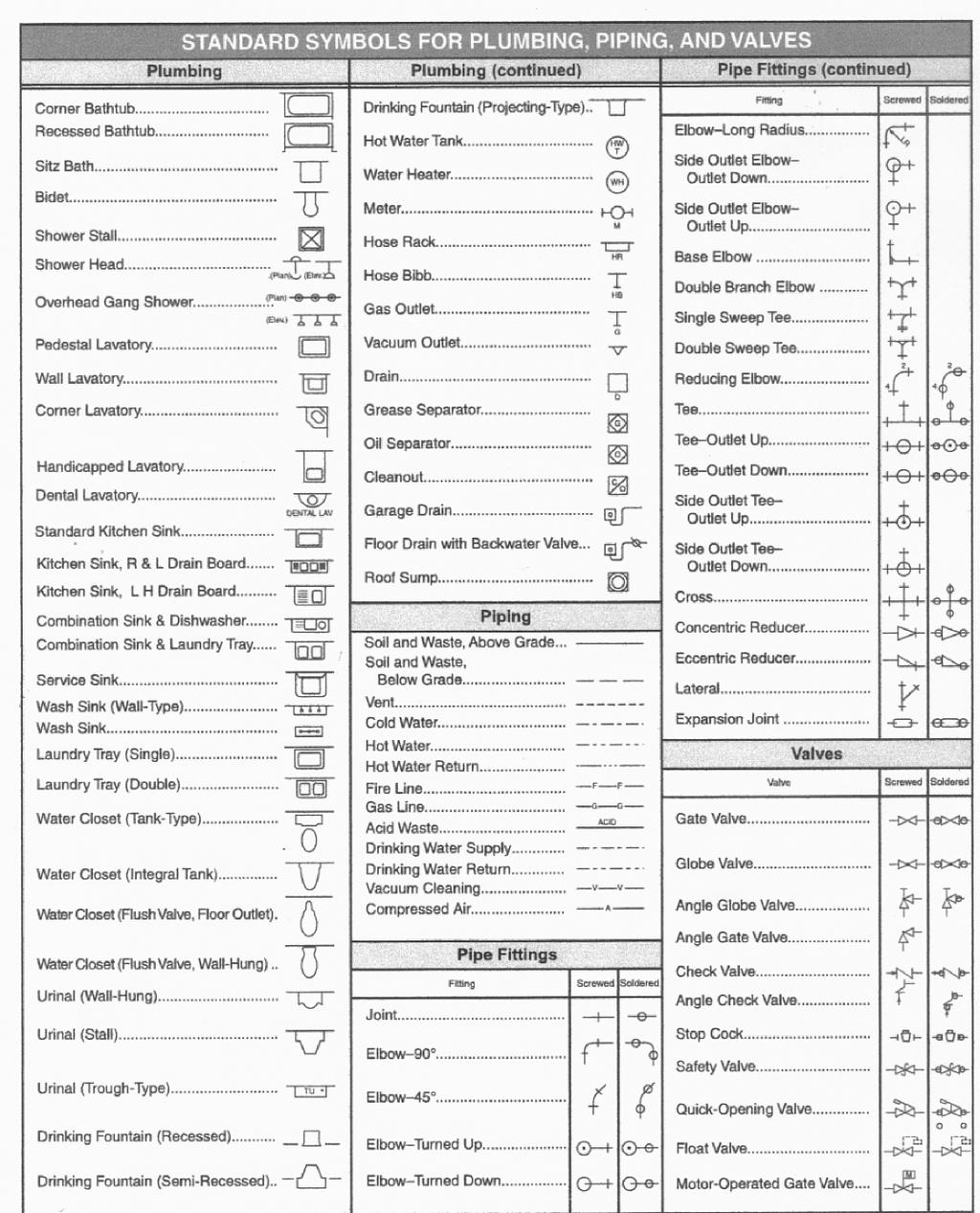
19 Definitions 19 Common Plumbing Symbols Note the difference in lines representing cold water, hot water, sanitary drains and vent pipe. Also note the symbols for a pipe turning up and down.
20 Definitions 20
21 Chapter 3 General Regulations Section 303 Plumbing products and materials must be tested or certified by a third party agency before being used. Tested means a third party does a one-time testing (for example, UL makes a one-time test of the product and publishes the results. No follow-up test or inspection is required.) Certified means the third party will test the product, then follow up with unannounced random tests or inspections. When using Table 303.4, it is important to understand which category the product falls under. For example, a lavatory faucet would be a water fixture fitting, as defined in Chapter 2. Therefore, third party certification is required. Section 307 Cutting, notching, or bored holes A 2 x 10 floor joist has an actual depth of 9-1/2 inches. According to the IPC, the largest hole that can be cut is 1/3 times the joist depth. Decimally 1/3 =.33 and 9-1/2 inches is 9.5 inches; therefore,.33 X 9.5 = inches. The largest hole may be inches in diameter. How to Convert a Fraction to a Decimal Equivalent Using Your Calculator Divide the top number by the bottom number. To get the decimal equivalent of 1/3 enter 1 divided by 3 =.33. Likewise, for 1/6, enter 1 divided by 6 =.166, or for 2/3, enter 2 divided by 3 =.66 A 2 X 8 ceiling joist may be notched 1/6th it s depth. What is the maximum size notch that can be cut if the actual joist depth is 7-1/2 inches?.166 is the decimal equivalent of 1/6 (1 divided by 6 =.166) and 7.5 is the decimal equivalent of 7-1/2 (7+ 1 divided by 2), which is
22 General Regulations 22 Therefore,.166 X 7.5 = inches (the largest allowable notch) is 40% of the width of 40% of the width of a single load bearing stud may be bored and 60% of a non-bearing stud or doubled up stud may be bored. Therefore, the largest hole that may be bored in a single load bearing 2 X 4 (3-1/2 actual) stud would be 1.4 inches (.40 X 3.5 = 1.4). To convert percent to a decimal equivalent, drop the % sign and move the decimal to the left two places. 30% =.30, 7% =.07, 150% = 1.50 According to Table 308.5, what is the maximum horizontal spacing of hangers for 10 foot lengths of cast iron pipes? Answer: 10 feet. Refer to footnote a. Under a floor joist, PEX must be supported every 32 inches. Section states that plastic water supply pipe cannot be pressuretested with air; however, all piping materials may be pressure-tested with water. Section does not disallow plastic drainage pipe from being tested by 5 PSI air. Therefore, plastic drainage pipe may be tested by air.
23 Chapter 4 Fixtures, Faucets aucets, and Fixture Fit ittings ings Section 403 The minimum number of plumbing facilities required in various occupancies. The following is an example for calculating the minimum facilities required in a 350-seat restaurant with 10 employees. The building measures 60 feet X 100 feet. Look at Table in the IPC. Find No. 1, A-2 Restaurants. Look first at sections 403.2, and as noted in the Classification column. When using any table, be sure to read all applicable footnotes. Section We must provide separate facilities for each sex if the minimum occupancy is greater than a certain number. Since 350 quests will be occupying this building, we must provide separate facilities for each sex. Section If an employee is any farther than 500 feet from a restroom then we need to build him another one. Our restaurant measures 60' x 100', so it is impossible for an employee to be farther than 500 feet from the restroom. Therefore, the employees may use the public facilities. However, we must add the number of employees to the number of guests. Also, note the restrooms may be located one story above or below the occupied story, but no higher or lower. Section states that public facilities shall be provided and that the public shall not have to travel more than 500 feet and more than one story up or down. Calculating number of water closets 1) Determine the number of occupants. 350 guests + 10 employees = 360 people 2) Determine number of males and females states that you should assume 50% for each sex unless statistical data indicate otherwise. For the example we would have the following: 360 people X.50 = 180 males 360 people X.50 = 180 females
24 24 3) Go to Table 403.1, Restaurants. Under the Water Closets column there is one WC for every 75 males and one WC for every 75 females. Since we have 180 males and 180 females we divide each by 75 to get the number of WC's required for each sex. 180 males/75 = 2.4 (3 water closets are required)* 180 females / 75 = 2.4 (3 water closets are required). Section Urinals shall not be substituted for more than 67% of the required water closets. In other words, two-thirds of the water closets may be substituted for with urinals. Therefore, the men's room may have 1 water closet and 2 urinals. (3 x.67 = 2.01 urinals, rounded down to 2. If the math came out to 1.9 urinals, then only one urinal could be substituted because you must round down) Calculating number of lavatories Under the Lavatories column it shows 1 per 200 of each sex. 180 male/200 =.9 (rounded up =1lavatory), 180 females / 200 =.9 (rounded up = 1 lavatory). Note- lavatories must be in the same room as the water closet (some codes have exceptions for daycare or K-5 classes, see section ) Calculating number of drinking fountains Under the Drinking Fountain column we use the total number of occupants (360). 360/500 =.72 (rounded up = 1 drinking fountain. Because this is a restaurant serving water, a water fountain is optional. See the note below. Important Notes Service sinks Drinking fountains are not allowed in toilet rooms. If the restaurant serves water, a drinking fountain is not required. (This exception only applies to restaurants. Refer to Section ) Bottled water dispensers may be substituted for not more than 50% of the required water fountains. IPC states that code enforcement official may approve bottled water or faucet water if there are less than 10 employees. Some states do not require water fountains in restaurants, nightclubs or bars, see Section 410 Under the other column, one service sink is required. Some states allow a can wash or mop sink as a substitute. Read all footnotes.
25 25 Section 405, Installation of fixtures Expect a question from this section, especially Section Sections These sections discuss the requirements for the installation of various fixtures. If you have a question about food grinders, can washes, showers, etc. it will likely be answered by these pages. Section Waste connection of washing machine Note: Clothes washer waste may be conveyed through a 2" trap and fixture drain. However, the branch drain or stack the fixture connects to, must be minimum 3". (see definition of horizontal branch drain or fixture branch). International Accessibility Code The accessibility code is relatively cut and dry. Almost all answers to questions dealing with handicap or disability issues will be found in Chapters 1, 11,12,13,18, 28, 30, or 39. Chapter 1 lists all the occupancy groups required to be made usable by persons with disabilities. The other chapters deal with specifics. Do not forget to use the index, as it is very detailed. Generally, all public toilets and toilets installed in commercial buildings must be made handicap accessible. The one exception is a private toilet room in a private office, which must be made to be adaptable to be accessible. Below are the highlights of the Accessibility Code: Each occupancy must have at least one assessable toilet. The turnaround area must be at least 60 inches in diameter. If the toe space under cabinets and fixtures is at least 8 ¾ inches high, then a maximum of 6 inches for each side may be used toward this requirement. The water closet must be 16 ½ /2 inches high, extend a maximum of 18 inches away from one side wall and a minimum of 18 inches from center of water closet to side wall, and flush handle to be on widest side no more than 44 inches off the floor.
26 26 The lavatory must extent a minimum of 17 inches from the wall, extend inches off the floor, and offer a 29-inche knee clearance beneath. Grab bars must be inches above the floor. In a stall, the bars must be on both side walls unless one sidewall is located greater than 18 inches from the edge of the water closet. Then, a rear bar must also be installed. The side bar must be at least 42 inches long and begin within 12 inches from the back wall. The rear bar must be at least 36 inches long and begin within 6 inches of the side wall. Urinals - The lip must be a maximum of 17 inches off the floor and extend a minimum of 14 inches from the rear wall. Drinking fountains - If drinking fountains are required, 50% of them must have spouts no more than 36 inches from the floor. If only one fountain is required, then both a high and low or a single combination hi/low fountain must be installed. If an odd number of fountains are required, round down the number and divide by 2 to determine the number of low fountains needed (5 fountains required, round down to 4, divide by 2 = 2 low fountains). Handicap stall dimensions: o Type I - Door swings inward- 60 inches wide, 59 inches deep (56 inches if wall hung WC is used). o Type II - Door swings inward- 60 inches wide, 95 inches deep (92 inches if wall hung WC is used. o All doors must be 32 inches wide. o If six or more WC stalls are provided, then an additional stall measuring at inches least 42 inches wide, 66 inches deep (69 inches deep with floor mounted WC) must be provided.
27 27 Water Heaters This chapter is very self-explanatory. Note that both the Gas and Mechanical Codes state that a water heater cannot be used for space heating unless listed for such use. The maximum temperature setting of a domestic water heater is 140 degrees, unless a master tempering valve is installed. Some states have laws stating that the maximum allowable temperature setting is 120 degrees when installed. The occupant, however, may re-set or request to have re-set the thermostat to a higher temperature. Section states that water heaters installed in garages must have the ignition source elevated 18 inches above the floor. This rule does not apply to water heaters that are resistant to flammable vapor ignition (FVIR). Today, all new gas water heaters meet this standard. Most electric and oil water heaters must have the ignition source elevated 18 inches (the bottom thermostat on an electric water heater arcs when energized; therefore it is an ignition source.)
28 Chapter 6 Water Supply and Distribution Section Separation of water service and building drain/sewer This section explains that the buried water line and sewer line cannot be closer than five feet to each other, either horizontally or vertically. However, if the sewer is made of ABS, PVC, or cast iron material listed in either Table or 702.3, you may place the waterline closer than five feet, but keep the water line at least 12 inches above the sewer pipe. Section 604 Design of water distribution system GPM (gallons per minute) fixtures require a certain amount of water to work properly. PSI (pounds per square inch) fixtures require a certain pressure to work properly. Design criteria for installing a plumbing fixture: Using a water closet, tank, close coupled (standard tank type water closet) as our example, look at Table The chart says it takes 3 gallons per 8 pounds per square inch pressure in order to work. Table says the water closet better not use more than 1.6 gallons per flush no matter what the GPM or PSI is. Table says, in order to assure the water closet will get 3 20 PSI (2006 IPC states 8 PSI) that a 3/8 supply pipe must feed it.

29 Sanitary Drainage 29 Table says, if you were to install a manifold capable of handling 15 GPM at a velocity of 4 feet per sec., then the manifold would have to be 1-1/4 inch. Note: Read footnote a located below Table 604.5, as some fixtures may qualify for smaller piping than indicated in the Table. For example, a 40-foot run from a central manifold to a kitchen sink may be served by a 3/8-inch pipe in lieu of a 1/2-inch pipe if the water pressure is greater than 35 PSI. Section Overflow pipes and drain pipes for water tanks Table says determine the capacity of the pipe that is supplying the water to the tank (tank size is irrelevant). If our tank is being supplied at a rate of 350 GPM, the overflow pipe must be 4 inches. The tank must have a drain. The minimum drain pipe size is determined using Table If the tank were 4000 gallons, a 2-1/2-inch drain pipe would be required.
30 Sanitary Drainage 30 Table Minimum required air gaps See Air gap (water system) in Chapter 2 (Definitions) of this guide for an illustration. This table specifies the minimum air gap requirement between the fixture rim and the water supply outlet. Read the footnote that describes the difference between away from a wall and close to a wall. To help visualize the difference, suppose we had a 1-1/2-inch diameter whirlpool spout protruding from a wall. If the inside edge of the spout opening is 4 inches away from the wall, it would be close to a wall because 4 inches is less than three times the spout diameter (1-1/2 inches x 3 = 4-1/2 inches). The air gap would also have to be 4-1/2 inches (3 x 1-1/2), as we would use the last row in the table, Effective opening greater than 1inch. wall 4 Spout-1-1/2 dia. tub trim Appendix E Sizing a water distribution system The method used to size a water distribution system in Appendix E is only one example of many approved engineering practices used to size piping. Section E states that alternative engineering practices are acceptable. If you try to read and follow along the segmented loss method example presented in Appendix E, you may become frustrated and confused. The following discussion will give you the basic principles for sizing water pipes. Understanding these principles should allow you to answer any test questions regarding pipe sizing.
 a developed length, which is the actual measured length and (2) an effective length, which is caused by the addition of fittings and valves.")
31 Sanitary Drainage 31 Understanding Friction Charts The length of a pipe is not the length of a pipe. A pipe has two lengths: (1) a developed length, which is the actual measured length and (2) an effective length, which is caused by the addition of fittings and valves. Table E103 lists the equivalent lengths of various fittings and valves. A 3/4-inch, 90-degree elbow has an equivalent length of 2.5 feet. If seven elbows were used in 130 feet of developed length of pipe, we would have to add feet (7 x 2.5) to the pipe to determine its total effective length. The total effective length (TEL) would therefore be feet ( ).
32 Sanitary Drainage 32 If the street pressure is 45 PSI, and you were to run a pipe with a total effective length of 100 feet, to a fixture requiring 12 gallons per 10 PSI, what size would the pipe have to be if the total pressure losses through a meter, backflow preventer, valves, tees and elbows equal 25 PSI. First, we must determine the pressure left to push the water down the pipe. This is called the available pressure or allowable pressure drop. Street pressure Pressure losses through meter, bfp, valves, tees, and elbows Pressure needed to operate fixture Pressure left to size pipe (allowable pressure drop) +45 PSI -25 PSI -10 PSI 10 PSI Second, go to Figure E103, located in Appendix E, Friction Loss in Smooth Pipe(type l in some codes). Place a dot at the intersection of 12 gallons per minute and 10 PSI pressure drop (Point A). It falls between a 3/4 inch and 1 inch (diagonal lines). If you were to install a 3/4-inch pipe, the GPM would be at 10 (Point B), therefore, the fixture would starve for water. A 1-inch pipe, however, will have the capability to deliver up to 20 GPM (Point C) before suffering a pressure loss below 10 PSI. A 1-inch pipe would be the correct choice. Go back to point B. At this point, a 3/4-inch pipe will deliver PSI. However, if we were to increase the pressure to 20 PSI without changing the pipe size, the new intersection will be at point D. If you draw a horizontal line to the left, it would indicate 17 GPM will flow through the 20 PSI. However, the velocity would be somewhat high at 10 GPM. Finding the allowable pressure drop for pipe measuring other than 100 linear feet (TEL) Notice at the bottom of the chart: PRESSURE DROP PER 100 FEET OF TUBE. The above illustration for using a friction chart is correct only if the pipe is exactly100 feet in total effective length. If the pipe is any other length, which is almost always the case, the pressure drop must be adjusted. To determine the adjusted-pressure drop of the above pipe (assume feet to be the TEL) we would use the following formula: Adjusted pressure drop = Available pressure drop x 100 = 10PSI x ft. = 6.78 PSI Total effective length The pipe must not allow a pressure drop greater than 6.78 PSI/100 feet
33 Sanitary Drainage 33 Velocity Now that we know the adjusted pressure drop (6.78 PSI) and the required flow rate (12 GPM), we can return to the friction chart and select the correct pipe size that in this example happens to remain 1 inch (Point E). Always check the velocity (feet per second, FPS) using the opposite diagonal lines on the friction chart. In this example the velocity is about 6 feet per second (8 FPS is max, 5 FPS is recommended). High velocities cause noise and pipe erosion. If the velocity is too high, you must select a larger pipe size by moving directly to the left, along the GPM line until an acceptable velocity is obtained. Practice question If you wish to obtain 12 GPM through a 450 foot (TEL) pipe at an available pressure of 10 PSI, what is the adjusted pressure drop and what size pipe would you select? Answer: 10 PSI x 100 = 2.22 PSI adjusted pressure drop PSI pressure drop shows 1 1/4-inch pipe should be selected (point F). Check velocity (less than 5 feet per second is OK) Let s throw a few more things into a piping system Below is a diagram of a commercial dishwasher installation. Fittings: -1 Tap -4 Elbows Globe valve 35 equiv. feet Dishwasher 2 0 G P M 10 PSI BFP 10 PSI pressure drop M PSI at meter and tap
34 Sanitary Drainage 34 In the above illustration, we have a number of items that contribute to pressure drop, as you will see below. These pressure drops must be subtracted from the street pressure in order to determine the available pressure left for sizing the pipe. Minimum pressure required to operate fixtures or appliances. Table lists the minimum pressure and flow rates to operate various fixture and appliances. If the appliance is not listed use the manufacturer s specs. Since this is a commercial dishwasher we will use the manufacturer s specification of 10 PSI. Developed length or measured length This is the actual measure length between the tap at the main and the fixture or appliance. The total developed length above is 188 feet. Valves and fittings When a valve or fitting is added to a system it restricts the flow. The resistance is expressed as equivalent feet. If a 90-degree elbow is equal to 2 equivalent feet than a 10-foot pipe with 1 elbow would offer the same resistance as a 12-foot straight pipe (10 ft. developed length +2 ft. equivalent length). In the above illustration we have four 90-degree elbows. Looking at Table E103B, (E103.3(5) in some codes), a 1-1/4-inch, 90-degree elbow is equivalent to 4 feet. Since there are four elbows, we must add 16 feet to the developed length of the pipe. The globe valve adds another 35 feet. When the equivalent lengths are added to the developed length, we have the total effective length. The total effective length of our pipe is 239 feet ( =239). You may be asking yourself, How do I know what size valves and fittings to use if I don t know the pipe size yet? Answer: You don t know. You must guess or estimate the final pipe size so you have a fitting size to work with. In the end, you may find you need a 2-inch pipe, then you must redo the procedure to be sure the 2-inch pipe works. Taps and tees Unlike valves and fittings, the pressure losses caused by taps and tees (off the main) are expressed in PSI. Table E103A, (E103.3(4) in some codes), lists these losses. At the main, our pipe is connected with a 1-1/4-inch tap; the required GPM is 20, therefore, the tap offers a pressure loss of.31 PSI. Note: Branch tees are expressed in equivalent lengths. See Table 103B (Table E (5) in some codes). Appurtenances
35 Sanitary Drainage 35 Includes meters, backflow preventers, and grease traps. The pressure drop produced by these items is expressed in PSI and can be found in the manufacturer s specifications. The backflow preventer in our illustration offers a pressure drop of 10 PSI. Height or elevation Water exerts a pressure of.433 PSI per foot elevation. A 10-foot high column of water would have 4.33 PSI at the base (10 ft. x.433 = 4.33). The height of our dishwasher connection from the tap is 22 feet. Therefore, there is a pressure loss of 9.53 PSI to lift the water (22 ft. x.433 = 9.53). If the dishwasher were located below the tap, say 15 feet, there would be a pressure gain of 6.50 PSI (15 x.433 = 6.50). Thus, we would add the gain to the street pressure. Let s size the pipe using the four steps below: 1) Using the following table, determine the available pressure to size pipe. A PRESSURE AT TAP +40 PSI B C D PRESSURE NEEDED TO OVERCOME HIEGHT (.43 3 lbs X 22 ) PRESSURE NEEDED TO OPERATE APPLIANCE PRESSURE DROP OF BACKFLOW PREVENTER PSI - 10 PSI -10 PSI E PRESSURE LOSS OF TAP -.31PSI F TOTAL PRESSURE LOSS PSI (B+C+D+E) AVAILABLE PRESSURE DROP PER 10.16PSI 100 FT. ALLOWED TO SIZE PIPE
36 Sanitary Drainage 36 2) Determine the total effective length (TEL) Total effective length = developed length + equivalent lengths = = 239 feet 3) Determine the adjusted pressure drop. Adjusted pressure drop = Available pressure x 100 Total effective length = x 100 = = 4.25 PSI 4) Go to Figure E103, located in Appendix E, Friction Loss in Smooth Pipe (Type l in some codes). Find the intersection of 20 gallons per minute and 4.25 PSI pressure drop (point G). The chart indicates a 1-1/4-inch pipe will work. Check the velocity; looks like about 5.5 fps- OK. Below is a sample commercial building. 5 flush valve WC, 2 lavatories D C Second floor branch 125 fu First floor branch 140 fu Tap PSI B A Meter pressure drop = 10 PSI BP pressure Drop = 9.50 PSI
37 Sanitary Drainage 37 1) Determine the available pressure drop. The available static pressure is the pressure remaining after the pressure losses due to valves, meters, devices and height are deducted from the street pressure. Pressure at city main Highest pressure needed to operate a fixture. See Table water closet, siphonic, flushometer valve Note: code lists a pressure drop of 35 psi Tap loss - (assume we have a 2 inch tap) Appendix E. The example above has a total of 318 water supply fixture units (WSFU). Table For Estimating Demand shows 318 WSFU = 127 gallons per minute (when a figure falls between two bins use the higher bin, 400 in this case).go to Table, "Loss of Pressure Through Taps and Tees", 127 GPM falls between , use 140. The pressure loss of a GPM = 2.20 Meter loss - manufacturer s specs says psi loss Backflow preventer-manufacturer s specs says 9.50 psi loss Allowance for future demand (estimate) Allowance for height of fixture. Water exerts a pressure of.433 pounds per foot of elevation. The highest fixture is 37 feet above the tap, therefore a pressure of psi will be lost in order to lift the water (37 x.433) Available pressure drop-this is the friction rate for sizing the piping system psi psi psi psi psi psi psi psi 2) Determine the longest effective length The longest length from the tap to point D. 257 feet is the measured or developed length. There are also 3 elbows from the tap to the farthest fixture. These fittings add friction loss to the system and are treated as equivalent lengths to pipe. Using table E (6), a 2 inch, 90-degree elbow is equivalent to 5.5 feet of straight pipe. Since there are 3 elbows between the tap and point D, we must add 16.5 feet to the measured length. There are 8 tees along the way, which are ignored because they
38 Sanitary Drainage 38 are not used by the farthest fixture. So, a total of 16.5 feet must be added to the 257 measured feet to come up with effective feet. 3) Determine the adjusted pressure drop Adjusted pressure drop = available pressure drop x 100 Longest total effective length =9.28 x = = 3.39 *This is the only pressure drop you will use to size all pipes connected to the same main. 4) Determine gallons per minute for each branch section of piping by converting the fixture units to GPM using the Table for Estimating Demand (appendix) 1st floor branch (140fu) = 77 GPM 2nd floor branch (125 fu) = 77 GPM 3rd floor branch (53 fu) = 54 GPM When sizing mains, total all fixture units it must carry, then convert to GPM using Table for Estimating Demand. 1) 127 GPM. 2) Main section B-C must deliver water to 2nd and 3rd floors ( = 178fu), 85.5 GPM. 3) Section c-d delivers only water to the third floor (53 fu) 54 GPM 4) Go to friction chart and size each section using the same adjusted pressure (3.39) for each section with its respective GPM requirement. Note: The velocities are close to 8 feet per second which is the upper limit but not forbidden by this code. Increasing the pipes by one size will slow the velocity if desired. 1st floor branch ( PSI) 2.5 2nd floor branch 9 PSI) 2.5 3rd floor branch (54 9 PSI) 2 Main- tap to B ( PSI) 2.5 Main- B-C (85.5 PSI) 2.5 Main- C- 3rd floor (54 9 PSI) 2
39 Sanitary Drainage 39 Chapter 7 Sanitary Drainage Section Slope of horizontal drainage piping Older codes required a 1/4 inch per foot slope for any pipe 3 inch diameter or less. This code has changed the rule to 2-1/2 diameter or less. A 3-inch drain now, needs only a 1/8-inch slope. (See Table 704.1) Section Connections to offsets and bases of stacks Horizontal branches cannot be connected to the base of a horizontal stacks or horizontal stack offsets within 10 times the diameter of stack. Section If there are more than four branch intervals above the offset, the horizontal branch cannot connect in any portion of the offset. The horizontal branch must be connected at least two feet above or below the offset. Table This table is full of important footnotes. You are assured to have questions from it on the exam. Note: A sanitary tee cannot lie on its side or come off the top of a drainage pipe under any circumstances. Double sanitary tees cannot be used to discharge back-to-back appliances with pumping action discharge. Most codes also prohibit the discharge of back-to-back water closets into double sanitary tees unless the water closet outlets are 18 inches or more from the stack. Double check both the footnotes in Table and Section

40 Sanitary Drainage 40

41 Sanitary Drainage 41 A wye is not permitted when the upper section of fixture drain is a vent because the vent opening is below the trap seal Continuous and semi-continuous flow fixtures A fixture with a continuous flow of 3 gallons per minute is equal to fixture units. Fixture units = GPM x 2 = 3 x A three-compartment sink must empty into an indirect waste receptor = 6 What is the minimum size drain and trap of the waste receptor? Table indicates a sink has a load factor of 2 fixture units for a sink. 2 fixture units x 3 sinks = 6 fixture units Table indicates a 4-inch drain and trap are required to handle 6 fixture units. Using the Drainage Tables Table Fixture units are probability factors for sizing drains in order to provide an uninterrupted flow of waste in pipes. The fixture units were developed by the National Bureau of Standards in 1940 and are still used today. As always, when using a plumbing chart, be sure to read the footnotes.
42 Sanitary Drainage 42 For our example, we will use a three-story house with two bathroom groups (1.6 GPF water closet). One group includes a bidet, laundry sink, kitchen sink with disposal, dishwasher, and clothes washer. The total fixture units for sizing the sewer, building drain, and stack are as follows: Fixture Bathroom group 1 Fixture units 5 Explanation Bathroom group 2 5* Some state codes allow a reduction in fixture units for additional full baths. Read the footnotes. DFU could be as low as 2 for each additional bath beyond the first one. Bidet 0 Section 202 defines a bathroom group as including a bidet. Therefore the bidet is included in bathroom group above. Laundry sink Kitchen sink Clothes washer Dishwasher 0 Dishwasher is included with kitchen sink First floor water closet First floor lavatory Total fixture units if additional bathroom groups only count as 2 DFUs Notes: Urinals and water closets have integral traps; therefore, the drainage pipe must be the size of the outlet. Although the trap size for a kitchen sink is 1 ½ inches, the vertical drain must be 2 inches according to some state codes. Read the footnotes.
43 Sanitary Drainage 43 Tables (1) and (2) Below is a schematic of the three-story home. The first floor has a kitchen sink, water closet, and lavatory. The second floor has two bathroom groups and the third floor has a clothes washer and sink. Each floor is served by a horizontal drain branch (to be a branch it must serve two or more fixtures). The fixture units are taken from Table and are in parentheses. The slope per ft. is 1/4 inch. Beginning at the sewer, we will size the drain system. According to Table 710.1(1), a 2-inch sewer can handle up to 21 DFUs. Therefore, a 2-inch sewer would be the obvious choice. However, according to the footnotes, a 3-inch sewer is the minimum size allowed because water closets are being served. Furthermore, many states have added footnotes stating 4 inches is the minimum size of any sewer. The building drain must be 3 inches. Again, Table 710.1(1) indicates a 2-inch drain will work, but the footnote states that the minimum size of any building drain serving a water closet shall be 3 inches. Stacks and horizontal fixture drains are sized using Table 710.1(2). The second column of the table is used to size the horizontal drain for each fixture branch. The third, fourth, and fifth columns are used to size the stack. Since this home has three branch intervals (three stories of plumbing), we must use the fourth column to size the stack. The stack between the building drain and first floor (first interval) is 3 inches. According to the table, a 2 1/2-inch stack will work, but remember, it has to serve two water closets. Therefore, its minimum size must be 3 inches. 2 Stack vent, see section horizontal branch drain, serves a water closet 3 horizontal branch drain, serves a washer. see section stack 3 stack 3 stack 3 horizontal branch drain, serves a water closet 3 horizontal branch drain serves a water closet 3 sewer (some states require sewer to be min. 4 )
44 Sanitary Drainage 44 Table also states that we cannot reduce the size of the pipe in the direction of flow. The horizontal drain for which the stack is serving is 3 inches. The stack between the first and second interval story is serving the second and third floors for a total of only 14* fixture units (5 FU +5 FU + 4 FU). Because the stack must serve the water closets on the second floor, it must be 3 inches. * Some state codes reduce the bathroom group DFUs for each additional bathroom added. For example, in our example above bathroom group 1 would count as 5 DFUs, but bathroom group 2 may only count as 2 DFUs and the total DFUs would be 17 instead of 20. Read every footnote below the tables. The stack between the second and third floor serves only 4 fixture units. Table 710.1(2) indicates a 1 1/2-inch stack will work. However, the second column indicates the horizontal drain on the third floor must be 2 inches. But, section states that if an automatic clothes washer is connected to a horizontal branch drain, the branch drain must be 3-inches in diameter. Section states, The size of drainage piping shall not be reduced in size in the direction of flow. Therefore, the stack, which is the third floor drainage pipe, must also be 3 inches. The horizontal drains for the first and second intervals must be 3 inches because they serve water closets. Note for states where the 2 nd bathroom group may be counted as 2 DFU. When sizing the horizontal drain branch for bathroom group 2, use five DFU, even if two were used to size the building drain and sewer. Factory locker room 10 showers, 3 urinals 12 w.c.s 10 lavatories C B 5 showers, 2 urinals, 8 w.c.s, 8 feetwashsink A SEWER
45 Sanitary Drainage 45 Sizing Drainage for a Factory Let s size the drainage system for the factory locker rooms in the illustration below. Determine fixture units Table gives us the fixture units needed to size the various components of the system. Branch at point B 5 showers x 2 FU = 10 fixture units 2 urinals x 4 FU = 8 fixture units 8 water closets x 4 FU = 32 fixture units 8 feet wash sink (5 faucets) x 1 = 5 fixture units (See 416.1) - 96 / 20 = 4.8 Total fixture units for interval B = 55 fixture units Branch at point C 10 showers (x2) = 20 fixture units 3 urinals (x) = 12 fixture units 12 water closets (x4) = 48 fixture units 10 lavatories (x1) = 10 fixture units Total fixture units for interval C = 90 fixture units Total fixture units on sewer (branches B + C) = 149 fixture units Determine component sizes 1/8 slope: 4 Table 710.1(1) column 3 Building 1/4 slope: 4 Table 710.1(1) column 4 Horizontal branch drain B: 4 Table (2) column 2 Horizontal branch drain C: 4 Table (2) column 2 Stack A-B: 4 Table (1) column 4 Stack B-C: 4 Table (1) column 4
46 Sanitary Drainage 46 Section 711 Yoke vent Sec. 915 Vent to lower floors When horizontal offset is locate more than 4 branch intervals (4 stories) below the top of the stack, a horizontal branch drain may not connect to the offset. It must connect at least two feet above or below the offset.
47 Chapter 8 Indirect and Special Waste The illustrations in Chapter 2 (Definitions) of this guide show the difference between an air break and an air gap. Basically, any food-handling equipment (excluding those for residential use), sterilizers, potable clear water waste (such as relief valves on water heaters), and swimming pools must have an air gap when drained. Non-potable clear water waste from equipment such as boiler drips or process tanks is the only type of waste that may be drained through either an air gap or air break. The size of all air gaps must be twice the waste pipe opening. If the waste pipe from the fixture or equipment is greater than two feet horizontally or four feet in total length, a trap must be installed on the waste pipe. Therefore, an indirect waste pipe from a food prep sink that extends 1½ feet horizontally and 3 feet vertically must be trapped before dumping into a drain receptacle. Sections and describe the requirements for waste receptors and washing machine standpipes; expect a question from these sections.

48 Chapter 9 Vents When waste water flows down a drain pipe, it must displace air that is in front of it. If this air is not given a place to go, such as up a vent, it will bubble into the fixture. This effect is experienced when emptying a soda bottle. Another reason for venting is to give the sewer gases a means to escape to the outside air. A third reason for venting is to prevent the discharged waste water from siphoning water from the primary fixture or other fixtures and traps. And lastly, venting also prevents water from backing up into lower fixtures. stack vent connected to a soil or waste stack vent stack
49 Vents 49 A stack is any vertical soil, waste or vent with or without offsets that extend through at least one story. A vent stack is for venting only and does not carry, nor is it designed to carry, any waste. A stack vent is that portion of a soil or waste stack above the highest fixture or branch drain connection Section 903 Every building must have at least one vent extended to the outside 1/2 size of building drain (for most states, 2 minimum size). A vent stack is only required in buildings with five branch intervals or more. When a vent stack is installed, its base must be connected to the drainage stack at or below the lowest horizontal branch on the stack. It may, however, be connected to the building drain as long as it is within a distance of 10 times the diameter of the drainage stack. VENT STACK Base of vent stack maybe connected anywhere between point A and B B Lowest horizontal branch 3 drainage stack A 30 (10x3 ) Section 904 The vent terminal (the part that goes out the roof) must be increased to three inches when located in freezing climates. Sections 914 and 915 (Refer to the illustration for Yoke vent in Chapter 2 (Definitions) of this guide.) If the building has more than ten branch intervals then a relief vent must be installed on the drainage stack at each tenth interval, beginning with the top floor. If there is a horizontal offset in the drainage stack then a relief vent must be installed if five or more branch intervals are above the offset.
 and vent. If the trap size is unknown refer to Table 709.1 in Chapter 7.")
50 Vents 50 Section 906 If the distance between a trap and vent is too great, the fixture drain will totally fill with water and siphoning of the trap seal may occur during discharge. Table dictates the maximum distance allowed between a trap weir (see illustration below) and vent. If the trap size is unknown refer to Table in Chapter 7. The drain size is determined by fixture units, using Table 710.1(2). Example: The maximum distance of a drain, sloped ¼-inch, measured from the trap weir to the vent fitting connection for a 1 ½-inch trap, shall be six feet. Note: Although it is not indicated in the table or written in the IPC, if the slope is greater than ¼-inch, the distance has to be reduced. Otherwise, the trap will be siphoned. Note: Even though a sink with a disposal has a 1-1/2-inch trap, some states require a 2-inch vertical drain. Read the footnotes. Section 908 Common vents The illustration below shows two fixtures at different levels sharing an individual vent. Use Table to size the vertical section between the fixtures. Note: A water closet is not allowed to be the upper fixture when common venting. common vent
51 Vents 51 The illustration below is an illustration of wet venting back-to-back bathrooms. C B A 2-1/2 The fixture units are obtained from Table 709.1: Drain size is from table 710.1(2) column 2 (total 12 DFU). Section A-C is a wet vent. Section A-B must handle 6 DFU. Table indicates a 2-1/2 pipe is needed as a wet vent. Section B-C must handle 2 DFU. Table indicates a 2 pipe is needed as a wet vent. The dry vent beyond point C must be 1-1/2 inches as section says vents, other than stack vents or vent stacks, must be at least one half the diameter of the drain served (3 inches). Section 911 Circuit vents Determine vent size - 4 dfu x 6 w,c. =24 dfu (Table709.1). Table 710.1(2) states that a 4 inch drain is required (this is a horizontal branch). Section states that vents other than stack vents or vent stacks must be 1/2 diameter of drain. Therefore, the circuit vent size is 2 inches.
52 Vents 52 Circuit vent for gpf public water closets (maximum of 8 fixture allowed to be circuit vented) Relief vent* Water closets must connect to drain horizontally *A relief vent must be installed when four or more w.c. are connected to a drain and the soil stack receives discharge from upper branches. Section 916 Vent pipe sizing There are only four rules for sizing vents. Remember these rules and you will have no trouble with vent sizing. 1) Table is used only to size stack vents, vent stacks and combination vent systems. 2) All other vents shall be sized as 1/2 the diameter of the drain served but never smaller than 1-1/4 inch. 3) If the developed length of the vent is greater than 40 feet, you must increase the size by one pipe size. 4) If the vent is a common vent or wet vent use Tables or Table Using Table The base of a vent stack is connected to a waste stack handling 450 DFU and extends 50 feet upward where it connects to a stack vent. The stack vent continues another 15 feet to the outside air. What is the minimum vent stack size if the waste stack is handling 3 branch intervals? The first thing we need to know is the size of the building drain stack. Table 710.1(2) indicates a 5-inch drain is needed to handle 450 DFU (540 DFU maximum).
53 Vents 53 Next, we ll turn to Table and find a row corresponding to a 5-inch waste stack and 450 DFU (about half way down the chart is 5-inch waste 490 DFU). The total developed length of our stack is 65 feet (50 feet + 15 feet). Therefore slide your finger to the right until you find a column containing at least 65 feet (250 is correct, 63 is too short). At the top of the chart it indicates a 4 vent stack is required. Sump vents (Using Table ) A 40-gallon per minute sewage pump is feeding a sump. A pipe with a developed length of 55 feet must vent it. What is the minimum allowed size for the vent pipe? Footnote (a) says to add 50% to the developed length for entrance and friction loses; therefore the maximum developed length would be 55 ft. plus 27.5 ft. (.5 x 55) for a total of 82.5 feet. Table indicates a 1-1/2 inch vent is needed.
54 Vents 54 Chapter 10 Sizing drains and vents using isometric drawings The inability to read and understand isometric drawings is the number one reason for most examinees' failures. The following pages contain isometric drawings of various plumbing configurations. It is important for you to complete the blanks for each drawing. Then review the answers and cited sections. Do not leave this chapter until you feel completely comfortable with sizing the following examples.
55 Both pipes are serving as wet vents. Pipe A has 1 dfu discharging into it (see Table 709.1). Table indicates a 1-1/2 pipe is required. Pipe B has 1 dfu discharging into it (see Table 709.1). Table indicates a 2 pipe is required. Vents 55 A B Size pipe A Size pipe B
56 Vents 56 J K B A C D E G H I F I H G A B C D E F G H I J K C E J K L A B I F H G C E D A B C D J F A B C D E F G H I J A B D E F G H I J K L
57 Vents 57 J K B C A D E F G H I I H G A 1-1/ B 1-1/ vent B is serving drain F. drain B is wet vent (Table C 1-1/2 Table D 2 Table 909.3, tub and lav (3 dfu) discharge into it E 3 Table 710.1(1) footnote a F 3 Serves water closets, plus cannot be smaller than E or G G 3 see E H 2 see D I 1-1/2 see C J A B I H C E D J A 3 Table 710.1(1) footnote a F B 3 Table 710.1(1) footnot a C 3 see A D 2-1/2 Table 909.3, 6 dfu discharge into it E 1-1/2 Table F 1-1/2 Table G 1-1/4 Table H 1-1/2 section 916.2, ½ of B I 1-1/4 Table J 1-1/2 see B K 1-1/4 see A K G J 2 Table 909.3, 2 dfu discharge into it E L C F A 3 -Table 710.1(1), footnote a A B D B 3 - Drain serves only 10 dfu (2 bathrooom groups), but WC requires 3 Table 710.1(1) footnote a C 2 - Table 710.1(2) horizontal drain servin 6 dfu D 1-1/2 Table 710.1(2) drain serves 3 dfu E 1-1/2 see D F 1-1/2 wet vent to tub, Table 909.3, lav (1 dfu) drains into it G 1-1/4 lav fixture drain (1 DFU), use Table H 1-1/4 section 916.2, vent to be ½ of drain C, 1-1/4 smallest allowable I 1-1/4 Vent for C (½ largest drain) J 1-1/4 see H K 1-1/4 see G L 1-1/2 see F
58 Vents 58 K A B J C I D H E G F All piping 1/4" slope A B C D E G H I J K F
59 Vents 59 K A B J C I D H E G F A 2" - vent for waste stack (stack vent) shall not be smaller than waste stack - Sec B 2" - Table 710.1(2) - Stack is greater than three intervals and serves 24 dfu C 2" - Same as above (B) D 2" - Same as above (B) E 2" - Same as above (B) F 2-1/2" - Table 710.1(1) - 2" pipe at 1/4" slope may only serve 21 dfu, must go with 2-1/2" G 2" - Table 710.1(2) - 2" horizontal branch will handle 6 dfu, (three showers) H 1-1/4" - Sec , vents other than stack vents or vent stacks to be 1/2 size of drain. I 1-1/4" - Same as above (H) J 2" - This is a drain serving as a wet vent for the shower. Use Table to size the pipe. Use the dfu of the upper fixtures (showers) K 2 " - Table 916.1, The vent stack must handle all 24 dfu, (use 42) It is over 30 feet in developed length (use 100), vent diameter indicates 2". Note: diameter of waste stack must be disregarded with this example.
60 Vents 60
61 Chapter 11 Traps, Interceptors, and Separators Traps Fixtures must be trapped within 24 inches vertically and in some newer codes, 30 inches horizontally from the fixture drain. (Refer to Section 1002.) The depth of seal must be at least two inches, but no more than four inches. The diameter (size) is according to Table Note: Trap cannot be larger than drainage pipe it s connected to.
62 Chapter 12 Storm Drainage Conductor Located inside a building Conductor - located inside a building Leader- located outside a building Storm drain accepts water from leaders and conductors Leaders, conductors, and storm drain illustration Size the storm drainage system for the above roof if it were 6300 square feet, located in Charlotte, North Carolina (choose another city if you re not in North Carolina). 1) Determine the hourly rainfall rate using figure (some state codes also have an Appendix B). Looks like 3.7 inches. 2) Using Table located in the rainfall rate column 4, we find 6300 square feet falls between 4600 and 8650; choose To the left, under diameter of leader we find 5 inches to be the correct leader or conductor size. If we wish to use a square pipe, the minimum size would have to be 5 x 5 (footnote a). 3) Using Table , if the storm drain slopes 1/8 inch per foot, then the drain would need to be 8 inches.
63 Storm Drainage 63 4) If we were to install gutters, we d go to Table and find that under 4 inches, rainfall the best we could do is 10 inch diameter gutters with a 1/4-inch per foot slope Vertical walls If the above building has a taller building attached directly to it, with a 100 ft. long wall extending 20 feet higher, then 1/2 of the exposed wall must be added to the roof of our building before sizing the roof drainage system. Our roof Neighbor s wall 20 x 100 = 2000 sq. ft. (2000 sq. ft. x.5 = 1000 sq. ft.) Square footage used to size roof drain components 6300 sq.ft sq. ft sq.ft. Section 1108 If the storm drain for our building is also used as a sanitary drain to discharge 375 DFU, we would size the drain and sewer as follows (paragraph ): Square footage of roof First 256 DFU Remaining 119 DFU 15.6 sq.ft./dfu 6300 sq. ft sq. ft sq. ft. 12,156 sq. ft. According to Table , a 12,156 sq. ft. roof requires a 10-inch 1/8-inch slope.
64 INTERNATIONAL PRIVATE SEWAGE DISPOSAL CODE This code, separate from the International Plumbing Code, may be required study material for some state exams. We have, therefore, provided the following explanation for sizing septic systems.
65 Chapter 13 Soil Absorption Systems Sizing an absorption field for other than one and two family residential To size the trench area required for a 36-unit, 2-bedroom apartment project on percolation class 2 soil use the following formula: Section Seepage pit sizing Area = number of units [Table 604.1(2)] Conversion factor [Table 604.1(2)] Absorption area from table 604.1(1) X X Area = 72 x 1.5 x 165 = 17,820 square feet According to Table 603.1, a single-family home on percolation class 2 soil requires 250-square feet of trench. If a 10-foot total diameter pit were to be used, what would the depth of the permeable strata be? Looking at column 1 of Table 605.3, to find the 10-foot, slide your finger to the right until at least 250 sq. ft. is located (251). Go to the top and you ll see 8 feet as the answer.
66 Chapter 14 Tanks The size septic tank for our apartment building from the example in the previous chapter would be calculated according to Section and Table as follows: Start with 750 gallons, then, according to Table , add 150 gallons for each bedroom. Tank size = 750 gallons + (150 gallons x 72 bedrooms) = ,800 = 11,550 gallons Obviously, you may use gallon tanks.
67 INTERNATIONAL FUEL GAS CODE Combustion air requirements Section Question: According to section 304.5, If the infiltration rate is unknown, does a room measuring 10 x 10 x 8 high with two 40,000 BTUH water heaters require outdoor air for combustion? Answer: Yes. The volume is less than 50 cu. ft. per 1000 BTUH Solution: Divide the total BTUH by ,000/1000 = 80 (1000's) Then multiply the number of 1000's by 50 cubic ft. 80 x 50 = 4000 If the room is less than 4000 cu. ft., then it needs combustion air. If it is more than 4000 cu. ft. no additional combustion air is required. The room is 10 x 10 x 8 = 800 cu. ft.; therefore, additional combustion air is required If the infiltration rate is known, the following formula may be used in lieu of the above to determine the minimum volume needed without having to add outside air. However, if the infiltration rate is know to be less than.40 air changes per hour, then the following formula must be used. Question: An area measuring 20 ft. x 30 ft. x 9 ft. is being heated by a 45,000 btuh fan assisted furnace. If the infiltration rate is.35 air changes per hour, is additional combustion air needed? For fan assisted appliances (most 80+ AFUE furnaces), the required volume must be greater than: (15 cu. ft/.35) x (45,000/ 1000 btuh) = x 45 = 1928 cubic feet The building is: 20 ft. x 30 ft. x 9 ft. = 5400 cubic feet Therefore, no additional outdoor air is required for this building. Section 304 Combustion air Question: Using the two opening method, how many sq. inches must each duct be if outside air is horizontally introduced into a confined space containing a 140,000 BTUH furnace? Answer: 70 sq. inches 140,000/2000=70
68 International Fuel Gas Code 68 Gas Pipe Sizing Divide to total BTUH in room by 2000 Appendix A gives an example for gas pipe sizing. Simply measure the distance between the meter and the farthest appliance; let s call this the distance factor, then use this distance factor to size each run off the main line. Each time part of the load is dropped off the main line resize the line using the remaining load and same distance factor. The toughest part is making sure you use the correct sizing table. Pay attention to specifics. Is the gas pressure less than 2 psi,.5 psi, 2psi, or 5 psi.? Is the pipe copper, or stainless steel? For the example below we will use Table 402.4(2) IFGC Note: 2003 and 2006 Gas Code may have slightly different charts but the methodology is the same. The distance from the meter to the farthest appliance is 82 (distance factor). Looking at Table 402.4(2) go down to the 90 foot row. You will size all pipe using this row. The number 13 directly to the right of 90 means a 1/4" schedule 40 metallic pipe will handle 13,000 BTUs (approx BTUs/cu. ft. nat. gas). To get pipe size, slide your finger across the 90 foot row until you find a pipe size large enough to handle the load. To size the main Beginning at the meter, the first 20 must handle the entire system load, 210,000 BTUH. Thus, the pipe must be 1-1/4 (good for 430,000 BTUH).
69 International Fuel Gas Code 69 After dropping off the water heater load, the next 20 must handle 170,000 BTUH. Thus the pipe must be 1 (good for 205,000 BTUH). After dropping off the furnace, the remaining 42 must only handle the gas log, 50,000 BTUH. Thus, the pipe must be 1/2 (good for 53,000 BTUH). To size the runs off the main The 10 pipe between the main and water heater must handle 40,000 BTUH. Thus, the pipe must be 1/2" (good for 53,000 BTUH). Remember to stay on the 90 foot row. The 25 pipe between the main and the furnace must handle 120,000 BTUH. Thus, the pipe must be 1 (good for 205,000 BTUH) Size L-P gas piping the same way once you ve passed the second stage regulator. To size between the first stage regulator (at the tank) and the second stage regulator (at the house), use the distance between regulators as the distance factor and size according to total connected load. Be sure to read and use the correct sizing Tables. Venting (section 503) Look at paragraph and figure This requirement is for chimneys and single wall vents (Not B Vent). Look at figure This requirement is for UL listed B and BW vents. Single appliance -Table 504.2(1) Sizing vents What size B vent is needed for a 160,000 BTUH, naturally ventilated appliance if the total vent height is 18 and the lateral 2? Under the height column you have to choose either 15 or 20. Remember this. The taller the vent the more capacity it has, therefore, if the 20 row is used the vent may be under sized. Always use the shorter height. In this case use 15. Now use the 2 lateral and select a vent size under NAT. A 5 vent will handle only 150,000 BTUH, while a 6 vent will handle 225,000 BTUH, therefore select a 6 vent. Venting two or more appliances with a single vent Table 504.3(1) When connecting two or more appliances to a common vent, the smaller appliance should be connected above the larger appliance.
70 International Fuel Gas Code 70 This Table has two parts. The top section is for sizing the connectors and the lower section is for sizing the common vent. First, size the connector of each appliance using vent height and connector rise. Second, size the vent using the total vent height and the total BTUH of all appliances connected to it. The same rule as above applies to height; always select the shorter height on the chart. Example: A standard 40,000 BTUH water heater with a connector rise of 3 feet and a 120,000 BTUH fan assisted furnace with a 1 foot connector rise are connected to a 22 foot common vent. Size the vent system. Solution Using the upper section of the chart, size the vent connectors of each appliance. Water heater Since the vent height is 22 ft., use 20 on the chart. Locate 3 feet under the connector rise column and slide to the right until you find at least 40 under a NAT column. At the top, it indicates a 3 connector will handle 42,000 BTUH. Furnace Again, at the 20 foot vent height row choose 1 foot in the connector rise column. Slide to the right until you find at least 120 under the FAN/MAX column. At the top it indicates a 5 connector will handle 157,000 BTUH. To size the common vent: Go to the lower section of the chart. Since one appliance is naturally vented and the other is fan assisted we will locate the 20 foot row and slide to the right until we reach 160,000 BTUH (total of both appliances) under FAN+NAT. A 5 common vent will work, as it will handle up to 183,000 BTUH. Note section Vent offsets This section states the capacities in the tables allow for no offsets (elbows) in single appliance vents with 0 laterals or two elbows for vents with laterals. If additional offsets are placed in the vent then the capacities must be reduced by 5% for each 45 degree elbow and 10% for each 90 degree elbow. Example: Using Table (1), a 10 foot vent with two offsets (laterals), 2 foot each, would have a total lateral of 4 feet. A 3 inch diameter vent, venting a NAT appliance is good for 57,000 btuh with a 5 foot lateral. However, since this vent has a second lateral which consists of two extra 90 degree elbows, the capacity must be reduced by 20% ( 10% x 2). Therefore the vent capacity will be reduced to 45,600 btuh (57,000 x.80) Be sure to read and apply to vent sizing Paragraphs and
71 International Fuel Gas Code 71 vent vent connector Appl.
72 CONTRACTING CTING BUSINESS
73 Contracting Business 73 Joey s Story Profit While Joey was walking down the street he found a yo-yo. On the following corner a friend saw it and purchased it from Joey for $1.25. Joey was delighted, as he had just made 100% profit. His cost was $0 and his sale was $1.25; therefore, all the money (100%) he received was profit. Joey thought he stumbled on a great money making idea; if he could only get a hold of more yo-yos he might get rich. So, he went to yard sales and bought up all the yo-yos he could find for 60 cents each. Again, he sold them for $1.25 each. This time he made only 65 cents per yo-yo or 52% profit. sale price $1.25 minus cost $.60 profit $.65 Joey s percent of profit is calculated below: Percent of profit = $ Profit/Sale price = $.65/$1.25 =.52 or 52% Note: Joey cannot make any more than 100% profit. In the business world there is no such thing as 150%, 1000%, or any other wild percentage above 100. Joey was on to something big. He thought he would manufacture his own yo-yos. His material costs would be $1.50, but since they would be new yo-yos he d get $4.00 each. Therefore, his profit would be $2.50 each; increasing his percentage of profit to 63%. Percent of profit = $Profit/Sales price = $2.50/$4.00 =.63 or 63% Well, Joey went into the yo-yo manufacturing business. He rented a building, bought a delivery truck, got a telephone, had the lights turned on, and purchased a wood lathe. He hired a secretary to send out sales letters, keep the books, and answer the telephone. Soon he was overwhelmed with orders and had to hire parttime labor to help make yo-yos. At the end of his first year he had sold 10,000 $4.00 each and his profit and loss statement (Income Statement) looked like the following:
74 Contracting Business 74 Joey s Yo-Yo Company Income Statement Revenue (sales) (4.00 x 10,000) $40,000 Direct costs Materials (1.50 x 10,000) 15,000 Labor 4,500 Total direct costs 19,500 Gross profit 20,500 Overhead Secretary salary 5,000 Rent 3,600 Telephone 1,200 Depreciation (for lathe) 1,500 Depreciation (for truck) 3,000 Office supplies (stamps, envelopes, etc,) 600 Total overhead 14,900 Total costs and overhead 34,400 Net income (net profit) $ 5,600
75 Contracting Business 75 Joey studied his income statement to find ways to increase his income. He calculated the direct costs to be 49% of sales: Direct cost/sales $19,500/ $40,000 =.4875 or 49% Direct costs are those costs directly associated with producing the product you are selling. In Joey s case, his cost of materials and labor increases or decreases depending on his sales volume; therefore materials and labor are direct costs. His gross profit is 51% of sales: $20,500 =.5125 or 51% $40,000 Gross profit is the profit made on sales before taking out overhead. His overhead is 37% of sales. $14,900 $40,000 =.3725 or 37% Overhead are those expenses incurred whether or not Joey does any business: secretary salaries, insurance, advertising, telephone bills and rent. These are all considered overhead. He must pay these expenses although he may not get any business. Overhead generally stays constant, it does not increase or decrease proportionally to the amount of sales volume. His total costs and overhead expenses were 86% of sales: $34,400 =.86 $40,000 And his net profit was 14% of sales: $5600 =.14 $40,000 How can Joey increase profit? Joey has three practical ways to increase profit: (1) raise the price of the yo-yo or (2) sell more yo-yos at the same price or (3) reduce expenses Looking at direct costs Joey has no choice because these costs increase or decrease directly as the sales volume fluctuates. Direct costs will always remain very close to 49% of sales. Overhead is relatively constant. He stands a good chance of increasing sales without increasing overhead or possibly increasing profit by cutting overhead.
76 Contracting Business 76 Reducing overhead expenses is tough, as overhead expenses occur whether or not he sells anything. Let s see what happens if Joey decides to increase his income by raising his price 10%: 1) Hopefully, his sales will increase to $44,000 (40, %). 2) His direct cost will increase 10%, to $21,450 (19, %). 3) His overhead should remain the same, $14,500. 4) Therefore, his new profit will be $ ) He will increase his profit from 14% to 18.3% (8050/44,000). 6) Meanwhile his overhead has dropped to 34% (14,900/44,000). Another question Joey might ask himself is, What would my sales have to be if I wanted to make $60,000 gross profit to cover both overhead and profit? If Joey s gross profit is traditionally running 51%, as his income statement indicates, then he would use the following formula: Sales needed for target profit = target profit $/ historical profit % = $60, = $117,647 Up to this point, Joey was keeping his books on a notebook he kept beneath the trash on the floorboard of his truck. He was beginning to accumulate a lot of customers who owed him money (account receivables) and he had a lot of suppliers who he owed money (accounts payable). It was becoming difficult to keep up with these accounts, so he hired Sally, a bookkeeper (more overhead). As daily orders and bills came in, Sally would enter the amounts in a general journal or day sheet. When she had time, perhaps once a week, she would transfer the information in the journal to ledgers. The ledgers were books containing a page for each account that he did business with. If the account was a customer, she would enter the amount owed to Joey in the debt column of the accounts receivable ledger. When the customer paid, she would enter the amount paid in the credit column. If the account were a supplier, she would enter the amount Joey owes in the credit column of the accounts payable ledger. When Joey paid the bill, she would enter the amount paid in the debt column. Each ledger had a third column in which a balance was kept. At the end of the month she would send a statement with the balance to each customer and a check for the balance to each supplier. To keep up with each employee s compensation, taxes, profit sharing, etc, Sally would keep a payroll ledger.
77 Contracting Business 77 In order to keep up with the money, she would keep a cash receipts and disbursement ledger. Whenever the company received money, she would debt cash in the ledger and whenever the company paid out money, for any reason, she would credit cash in the ledger. It was like keeping a checkbook. At the end of the month, Sally would prepare a balance sheet to let Joey know how much he owned (assets), how much he owed (liabilities), and how much he was worth (equity). She also prepared an income statement to let Joey know where his money was going and if he was making a profit. The income statement included his total sales (revenue), labor and material costs (direct costs), general and administrative expenses (overhead), and his net profit (income). Now that Joey has all these financial tools, he can use them to plan his business strategy. If Joey wants to make $75,000 and he knows his net profit is running about 12.75%, he would have to increase sales to $588,235 Sales = Net income/net profit % = $75,000/.1275 = $588,235 END OF JOEY S STORY Now that you know Joey s story, let s look at the contracting business. *How to price a job. Suppose you purchase a gas water heater for $350 and it costs $150 for venting, piping plus $140 labor, and $35 for a permit. If your company overhead is 15%, what will the sales price of the job be if you want to make 20% net profit? First, you need to calculate the cost of the job Water heater $350 Venting and piping $150 Labor $140 Permit $35 Total job cost $675
78 Contracting Business 78 Second, you must calculate a price that will include: your cost + overhead + profit. We know the cost is $675 and we know the overhead and profit will be 35% (15%+ 20%) of the sales price. To calculate sales price (this method must be used on the exam): 1) Subtract your overhead and profit % from 100% =. 65 or 65% 2) Divide the cost by the above answer. $675/.65 = $ sales price Note: Most students would add 35% to the cost or multiply the cost by 135% and come up with $ This is not correct. *What if? If you were working on a net profit of 15%. What would your annual sales have to be to make $75,000? Solution Sales = Target profit amount/profit % = $75,000/.15 = $500,000 If you increase your % net profit to 25%, what would your sales have to be? $75,000/.25 = $300,000 Moral: The above contractor increases his prices by 10% and only has to do 60% of the work he used to do. * Similar problems will likely be on the test.
79 Contracting Business 79 INCOME STATEMENT An income statement is an orderly accounting of where the revenue came from, a list of the expenses, and a total of the gross and net profit or loss. The figures entered in the statement may be based on an accrual or cash basis. An accrual basis means your accounting system uses income and expenses that are expected to be received or incurred, while a cash basis uses income and expenses that have actually occurred. If Joey sells $1000 worth of yo-yos on credit, he will show $1000 as income on an accrual basis. However, on a cash basis, he will show no income, as he has not received the funds yet. Once you select a basis for your accounting method you must continue using it. You cannot switch back and forth from year to year. Items found on an income statement are listed below. Revenues Revenues are the same as sales of the product your company is primarily involve in. If you sell a water heater, the money received is revenue (sales). If you sell a surplus truck, which is not your primary business, then the money received is considers a gain (or loss) on sale of asset. See Other Income/Expenses. Direct Costs Any money you spend (usually labor and material) to complete a particular job is considered direct costs. Job A might require $2600 (direct costs) in labor and material while Job B requires $4800 (direct costs) in labor and material. Project Overhead Project overhead is money spent just to do the job but does not contribute to its completion. Examples would be superintendent s salary, expense of vehicles used for the job, special insurance, repairs on job equipment or office trailer rent. Cost of Construction The total of direct costs and project overhead is called cost of construction. In accounting terms it is sometimes called cost of goods sold. Gross profit Gross profit is revenue (sales) minus cost of construction (cost of goods sold). On the income statement, the revenue is $1,077,760. If you deduct the cost of construction (which includes direct cost and job overhead), of $842,460 from the revenue we would have $235,300 gross profit.
80 Contracting Business 80 If you purchase an air conditioner for $600 and pay $150 labor to install it, the total cost of construction would be $750. If you sell it for $1400, your gross profit would be $650. General and Administrative Expenses Also called company overhead, general and administrative expenses are any monies spent to keep the doors open and bring in business, whether you do any business of not. Your salary, the office salary, stamps, insurance, telephone, rent and advertising are examples. Depreciation Most expenses are cut and dry. If you spend $160 on utilities, the expense is $160. Depreciation, on the other hand, must be calculated. Two common methods used to calculate depreciation are the straight line and the accelerated depreciation method. To illustrate each method we will depreciate a backhoe purchased in July for $19,500. Under the straight line method, $5000 will be estimated to be the salvage value (what you think you can sell it for at the end of five years); therefore, $14,500 is to be depreciated evenly throughout a five-year period. In each of the five years you can deduct $2900. Since you purchased the backhoe in July and your fiscal year ends in December, you are only entitled to six months depreciation the first year, which is 1/2 year or $1450. The fifth year of ownership will fall on July so you will also get 1/2 of that year s depreciation ($1450). IRS rules allow for methods of accelerated depreciation, which allows a business to claim a higher amount of depreciation for assets in the first years of operation. One such method is the double declining balance method. For example; the backhoe above has a life of five years, therefore each year 1/5 or 20% may be depreciated. The double declining balance method allows the business to take 40% (double the 20% allowed under the straight line method above) of the asset balance as depreciation expense each year until its useful life comes to an end. Depreciation Book Value Year 1.40 x $19500 = $7800 balance = $11700 Year 2.40 x $11700 = $4680 balance = $7020 Year 3.40 x $7020 = $2808 balance = $4212 Etc.. What happens if the backhoe is sold after six years for $3500? If, you used the straight line method you will have to show $1500 as a loss on sale of assets under other income/expenses on your income statement because the books are showing it is worth $5000. If you used the accelerated depreciation method, $3500 would
81 Contracting Business 81 show up as again in sale of assets because the books are showing it to be worth $0. Net income This is the profit made after every conceivable expense has been deducted from revenue. A corporation (except S type) will also deduct taxes as an expense. Proprietorships, S type corporations and partnerships do not deduct taxes on their income statements. Taxes on these type organizations are paid as ordinary income taxes. Using the example above where you made $650 gross profit on the air conditioner, your net income or net profit would be what is left after deducting your overhead (gas, cost of invoice, insurance, truck depreciation, etc ). Financial Ratios Many exams will ask you to calculate financial ratios. Usually, study guides are provided by each individual state and contain numerous financial formulas. Test questions may give you more information than you need, but will be specific in what is being asked. Example: Acme Heating has an annual revenue of $875,000. Its total debt is $125,000 and its equity is $145,000. What is the Debt/Equity Ratio? Solution: Looking at one popular business guide, Business and Project Management for Contractors, you will see the formula for Debt/Equity Ratio. The formula only needs two figures, total debt and equity. The revenue figure ($875,000) is not needed. Debt to Equity Ratio = $125,000Debt/$145,000 Equity Payroll Taxes =.862 Three federal tax items are withheld from an employee s income: 1) Income tax from circular E chart. 2) Social security tax (employees share = 6.2%. (Rates as of 2010, current rates should be proved on exam) 3) Medicare tax (1.45%). Using the information and tax tables on the next page, obtain the net take home pay of a married employee with 3 allowances (dependents) making $483 weekly. Be sure to take out all three items above. Solution: Using the circular E table on the next page, go down the first two columns to find the employees pay range Slide your finger to left to column under 3 withholding allowances. You should see $19.
 -29.94 Medicare tax ($483x.0145) - 7.")
82 Contracting Business 82 Base pay $ Fed income tax from table Social security ($483 x.062) Medicare tax ($483x.0145) Take home pay $427.06
ENERGY MARKETING SERVICES
 1 IMPORTANT STUFF This manual has been designed as a supplemental aid for students preparing to take the Plumbing Exam based on the international codes. It is not intended to replace any manuals or material
ICP Plumbing Exam. Name: Carefully read each question and then circle the letter of the best answer.
 ICP Plumbing Exam Name: Date: Score: Carefully read each question and then circle the letter of the best answer. 1. A 1 inch diameter faucet, where the inside edge of the spout opening is 2.5 inches away
MATERIALS Traps TRAPS. No. IPC IRC Description
 MATERIALS Traps TRAPS MAX " MAX 0" No. IPC IRC Description 00. P0.6 00. P0.6 00. P0. 00. () P0.6 Exc. Vertical distance from fixture to the trap weir can not exceed ". Horizontal distance from the fixture
1 Exam Prep Plumber s Handbook Tabs and Highlights
 1 Exam Prep Plumber s Handbook Tabs and Highlights These 1 Exam Prep Tabs are based on the Plumber s Handbook Revised 2006. Each Tabs sheet has five rows of tabs. Start with the first tab at the first
IPC Plumbing Exam. Name: Carefully read each question and then circle the letter of the best answer.
 IPC Plumbing Exam Name: Date: Score: Carefully read each question and then circle the letter of the best answer. 1. A vent stack handling 25 dfu s with a developed length of 35 feet shall be inches minimum
Sanitary Drainage Systems
 11.1 MATERIALS See Section 3.1. Sanitary Drainage Systems 11.2 BUILDING SEWERS AND BUILDING DRAINS 11.2.1 Sewer or Drain in Filled Ground Chapter 11 Building sewers or building drains that are installed
IPC Plumbing Exam. Name: Carefully read each question and then circle the letter of the best answer.
 IPC Plumbing Exam Name: Date: Score: Carefully read each question and then circle the letter of the best answer. 1. The minimum air gap for a fixture with an effective open of 1/2", located away from a
STACKS AND STACK VENTS
 CHAPTER 9 VENTS SECTION 901 GENERAL 901.1 Scope. The provisions of this chapter shall govern the materials, design, construction and installation of vent systems. 901.2 Trap seal protection. The plumbing
Level I Chapter 1 Worksheet
 Chapter 1 Worksheet 1. For applicability requirements of the Plumbing Code, refer to: a. Building Code b. Administration and Enforcement Code c. Plumbing Code d. Residential Code 2. The provisions of the
CHAPTER 31. VENTS Reserved 2003 INTERNATIONAL RESIDENTIAL CODE 425R
 CHAPTER 31 VENTS Reserved 2003 INTERNATIONAL RESIDENTIAL CODE 425R This page left intentionally blank. 426R 2003 INTERNATIONAL RESIDENTIAL CODE For SI: PIPE SIZE (inches) TABLE P3107.3 COMMON VENT SIZES
Read Only Document Not For Distribution
 Chapter 9 Indirect Waste Piping and Special Wastes 9.1 INDIRECT WASTES 9.1.1 General Drains from fixtures, fixture compartments, equipment, appliances, appurtenances, and other devices requiring protection
GIANT. Little. Guidelines for Sizing. Pump Company. Sewage Pumps & Systems. Sewage Pumps & Systems
 Sewage Pumps & Systems GIANT Little Pump Company Guidelines for Sizing Sewage Pumps & Systems These guidelines cover the steps that need to be taken to accurately select the correct sewage pump and applicable
Summary of BBS Proposed Ohio Plumbing Code Rule Changes October 2016
 Summary of BBS Proposed Ohio Plumbing Code Rule Changes October 2016 Ohio Administrative Code Rule Number OPC Section IPC origin Reason for proposed 4101:3-2-01 Alternate on-site 2015 Added definition
APPENDIX A. A 3.2 Determine the elevation of the highest. A 3.3 Subtract the sum of loss in static pressure
 APPENDIX A RECOMMENDED RULES FOR SIZING THE WATER SUPPLY SYSTEM Because of the variable conditions encountered, it is impractical to lay down definite detailed rules of procedure for determining the sizes
2016 Plumbing Supplemental Plan Review List
 Building Division 555 Santa Clara Street Vallejo CA 94590 707.648.4374 2016 Plumbing Supplemental Plan Review List POTABLE WATER SYSTEM P1. Specify which fixtures are for private use and which are for
Wastewater. Guidelines for Sizing mscdirect.com. Call MSC today to learn about the latest LittleGiant products.
 Wastewater Guidelines for Sizing Features These guidelines cover the steps which need to be taken to accurately select the correct sewage pump and applicable systems to use in sewage ejectors. Work through
SCHOOL DISTRICT PALM BEACH COUNTY BUILDING DEPARTMENT PLAN REVIEW CHECK LIST -- PLUMBING
 SCHOOL DISTRICT PALM BEACH COUNTY BUILDING DEPARTMENT PLAN REVIEW CHECK LIST -- PLUMBING 3300 SUMMIT BOULEVARD WEST PALM BEACH, FLORIDA 33406 TEL (561) 688-7687 FAX (561) 688-7654 http://www.palmbeach.k12.fl.us/fm/bd/index.htm
1 Exam Prep Plumbing State Contractors Practice Exam 2
 1 Exam Prep Plumbing State Contractors Practice Exam 2 1 According to Chapter 64E-6, when sizing a grease interceptor used in a restaurant, the correct formula is. A. (S) x (EW 12) x (LF) B. (S) x (GS)
CHAPTER 9 VENTS SECTION
 CHAPTER 9 VENTS SECTION 901 GENERAL 901.1 Scope. The provisions of this chapter shall govern the materials, design, construction and installation of vent systems. 901.2 Trap seal protection. The plumbing
CALIFORNIA PLUMBING CODE MATRIX ADOPTION TABLE APPENDIX A - RECOMMENDED RULES FOR SIZING THE WATER SUPPLY SYSTEM 1 2 1/AC AC SS SS/CC
 CALIFORNIA PLUMBING CODE MATRIX ADOPTION TABLE APPENDIX A - RECOMMENDED RULES FOR SIZING THE WATER SUPPLY SYSTEM Adopting Agency BSC SFM HCD DSA OSHPD CSA DPH AGR DWR CA 1 2 1/AC AC SS SS/CC 1 2 3 4 Adopt
CHAPTER VI BUILDING PLUMBING
 CHAPTER VI BUILDING PLUMBING 6.1. INTRODUCTION The chapter covers questions related to water demand, distribution and drainage. The basic principles for planning and installing common plumbing systems
CHAPTER 9 VENTS. run undiminished in size and as directly as possible from the building drain through to the open air above the roof.
 CHAPTER 9 VENTS SECTION 90 GENERAL run undiminished in size and as directly as possible from the building drain through to the open air above the roof. 90. Scope. The provisions of this chapter shall govern
APPENDIX L ALTERNATE PLUMBING SYSTEMS
 ALTERNATE PLUMBING SYSTEMS L 1.0 General. L 1.1 Applicability. The intent of this appendix is to provide clarification of procedures for the design and approval of engineered plumbing systems, alternate
Denotes a new question! Denotes a revised/revisited question. September 2009 General:
 General: 1) (Q) What does a contractor/permit holder have to supply for an inspection? (A) Section 107.2 of the NC Administrative Code states that it is the duty of the permit holder to provide access
Plumbing Guidelines 2015 Minnesota Accessibility Code Based on the 2012 IBC and 2009 ANSI A117.1
 Plumbing Guidelines 2015 Minnesota Accessibility Code Based on the 2012 IBC and 2009 ANSI A117.1 This document provides basic and fundamental information for accessible plumbing fixtures, toilet rooms
Methods of Venting Plumbing Fixtures and Traps in the 2018 IPC
 People Helping People Build a Safer World Methods of Venting Plumbing Fixtures and Traps in the 2018 IPC Installation, Flexibility and Opportunity for Savings Lee Clifton, Senior Director of PMG Resources,
Plumbing Guidelines 2012 IBC/ANSI A
 Plumbing Guidelines 2012 IBC/ANSI A117.1-2009 This document provides basic and fundamental information for accessible plumbing fixtures, toilet rooms and bathing facilities. It is not intended to replace
Plumbing. Definitions. Background Factors. Air Chambers. Air Gap (Drainage System) Air Gap (Water Distribution System) Air Lock.
 Air Gap (Water Distribution System) Air Lock.") Plumbing Plumbing may be defined as practice, materials, and fixtures used in the installation, maintenance, and alteration of all piping, fixtures, appliances, and appurtenances in connection with sanitary
Plumbing Plumbing may be defined as practice, materials, and fixtures used in the installation, maintenance, and alteration of all piping, fixtures, appliances, and appurtenances in connection with sanitary
Read Only Document Not For Distribution
 Chapter 5 Traps, Cleanouts and Backwater Valves 5.1 SEPARATE TRAPS FOR EACH FIXTURE a. Plumbing fixtures shall be separately trapped by a water seal trap placed as close as possible to the fixture outlet.
APPENDIX J ILLUSTRATIONS
 The following figures have been included in the 1994 edition of the Standard Plumbing Code to aid in interpreting this code. The figures are not to be construed as superseding the written text, but merely
CHAPTER 10 TRAPS AND INTERCEPTORS
 CHAPTER 10 TRAPS AND INTERCEPTORS 1001.0 Traps Required. 1001.1 Each plumbing fixture, excepting those having integral traps or as permitted in Section 1001.2, shall be separately trapped by an approved
c. Direct or indirect?
 ~ \ 1.) GENERAL a. Definitions: Chapter B Code References (1) Air-break Comm 81.01 (5) (2) Air-gap, drain system Comm 81.01 (6) (3) Flood level rim Comm 81.01(102) (4) sink Comm 81.01(105) (5) Indirect
Pro Vent TM. Provent Systems Inc Capital Circle Lawrenceville Georgia
 Pro Vent TM Guide to Design and Usage Provent Single System Handling Installation Corrosion Ease Simplicity Resistance IPMO Copyright (c) 2014, Pro Vent Systems Inc., plus *2016 Revisions ll Rights Reserved
Land Use and Environmental Service Agency (Code Enforcement) Plumbing 2010
 Plumbing 2010") General: 1) (Q) Who enforces the cutting and notching requirements found in the plumbing code? (A) The plumbing inspector would question the contractor initially. A building inspector would either take
General: 1) (Q) Who enforces the cutting and notching requirements found in the plumbing code? (A) The plumbing inspector would question the contractor initially. A building inspector would either take
2015 UPC Chapter 8 Indirect Wastes RV
 PLEASE DO NOT BOOKMARK ANY ANYTIMECE WEBPAGES! Our system will remember the last page you viewed when logging out and back in but please DO NOT exit out when taking a test. Your place will NOT be saved.
2009 IPC ,IMC Q &A ANDIFGC
 2009 IPC,IMC ANDIFGC Q &A TABLE OF CONTENTS PREFACE.... ix ABOUT THE INTERNATIONAL CODE COUNCIL...x IPC CHAPTER 1 SCOPE AND ADMINISTRATION...1 Section 101 General... 1 Section 102 Applicability... 1 Section
TABLE OF CONTENTS. CHAPTER 2 DEFINITIONS General Applicability Definition of Terms General...
 TABLE OF CONTENTS CHAPTER 1 ADMINISTRATION................1 101.0 Title, Scope, and General...........1 101.1 Title............................1 101.2 Purpose.........................1 101.3 Plans Required...................1
Special Requirements For Health Care Facilities
 Chapter 14 Special Requirements For Health Care Facilities 14.1 GENERAL This Chapter applies to special fixtures and systems that occur in health care facilities and to the special plumbing requirements
PLUMBING INSTALLATIONS
 PLANNING, PROPERTY AND DEVELOPMENT DEPARTMENT PLUMBING INSTALLATIONS A homeowner guide to plumbing requirements for single-family dwellings November 2017 contents Permit Requirements... 3 Inspection Requirements...
Pipe Sizing Table. Hydraulic Load Served (fixture units)
") MODULE 1 INTRODUCTION Notes: A Pipe Type Horizontal branch Pipe Sizing Table Hydraulic Load Served (fixture units) Size (in.) Code Reference 2 + 1.5 = 3.5 2 7.4.9.1.(1) B Soil stack 13.5 + 13.5 = 27 3
MODULE 1 INTRODUCTION Notes: A Pipe Type Horizontal branch Pipe Sizing Table Hydraulic Load Served (fixture units) Size (in.) Code Reference 2 + 1.5 = 3.5 2 7.4.9.1.(1) B Soil stack 13.5 + 13.5 = 27 3
CHAPTER 10 TRAPS AND INTERCEPTORS The vent pipe opening from a soil or waste No more than one (1) approved slip joint
 approved slip joint") CHAPTER 10 TRAPS AND INTERCEPTORS 1001.0 Traps Required. 1001.1 Each plumbing fixture, excepting those having integral traps or as permitted in Section 1001.2, shall be separately trapped by an approved
CHAPTER 10 TRAPS AND INTERCEPTORS 1001.0 Traps Required. 1001.1 Each plumbing fixture, excepting those having integral traps or as permitted in Section 1001.2, shall be separately trapped by an approved
A hydronic system controls comfort by delivering heated or cooled fluid to the conditioned space through pipes.
 Introduction to Hydronics A hydronic system controls comfort by delivering heated or cooled fluid to the conditioned space through pipes. Hydronic heating systems use hot water or steam to deliver the
CHAPTER 10 TRAPS AND INTERCEPTORS TABLE 10-1 HORIZONTAL LENGTHS OF TRAP ARMS (EXCEPT FOR WATER CLOSETS AND SIMILAR FIXTURES) 1, 2
 1, 2") CHAPTER 10 TRAPS AND INTERCEPTORS < 1001.0 Traps Required. Each plumbing fixture, excepting those having integral traps or as permitted in Section 1001.1, shall be separately trapped by an approved type
CHAPTER 10 TRAPS AND INTERCEPTORS < 1001.0 Traps Required. Each plumbing fixture, excepting those having integral traps or as permitted in Section 1001.1, shall be separately trapped by an approved type
TABLE OF CONTENTS. Part I Administrative... 1
 Part I Administrative............................ 1 CHAPTER 1 ADMINISTRATION............... 1 R101 Title, Scope and Purpose.................... 1 R102 Applicability.............................. 1 R103
plumbing for greywater
 plumbing for greywater october 2015 christina bertea ~union trained journeywoman plumber (1978) ~plumbing contractor (1996) ~greywater action singingwater@jps.net plumbing for greywater basic parts of
Chapter 4: Fixtures, Faucets & Fittings:
 Table of Contents Chapter 1 Administration 0 Chapter 2 Definitions 0 Chapter 3 General Regulations 0 Chapter 4 Fixtures, Fau & Fit. 12 Chapter 5 Water Heaters 14 Chapter 6 Water Supply & Dist. 10 Chapter
CHAPTER 4 FIXTURES WHAT FIXTURES ARE REQUIRED? SINGLE-FAMILY RESIDENCE
 PlumbingCode06_ch04 5/29/06 8:11 AM Page 1 CHAPTER 4 FIXTURES There is much more to fixtures than meets the eye. Fixtures are a part of the final phase of plumbing. When you are planning a plumbing system,
PLAN REVIEW SUBMITTAL GUIDE
 PLAN REVIEW SUBMITTAL GUIDE Plans, specifications and other construction documentation for the initial plan review should be as complete as possible at the time of submittal. Use this convenient guide
2012 Virginia Plumbing Code & VRC (Plumbing) Update Training
 Update Training") 2012 Virginia Plumbing Code & VRC (Plumbing) Update Training ----------------------------- Henrico County Department of Building Construction and Inspections Introduction This presentation was prepared
2012 Virginia Plumbing Code & VRC (Plumbing) Update Training ----------------------------- Henrico County Department of Building Construction and Inspections Introduction This presentation was prepared
Matrix of changes for the National Standard Plumbing Code July 2013
 Matrix of changes for the National Standard Plumbing Code July 2013 Item # Section Number Person Submitting Change Committee Action 10-77 10.20.8 and Table 3.1.3 XI Certification 10-82 12.16 Size and Lengths
1 Exam Prep Solar Water and Pool Heating Manual (UCF) Questions and Answers (Plumbing Contractor)
 Questions and Answers (Plumbing Contractor)") 1 Exam Prep Solar Water and Pool Heating Manual (UCF) Questions and Answers (Plumbing Contractor) 1. For year-round use, a collector tilt of degrees works best for a project located in Tampa, Florida.
1 Exam Prep Solar Water and Pool Heating Manual (UCF) Questions and Answers (Plumbing Contractor) 1. For year-round use, a collector tilt of degrees works best for a project located in Tampa, Florida.
2015 UPC CODE - CHAPTER 8 INDIRECT WASTES
 801.0 General. 2015 UPC CODE - CHAPTER 8 INDIRECT WASTES 801.1 Applicability. This chapter shall govern the materials, design, and installation of indirect waste piping, receptors, and connections; and
STUDENT NOTES Plan, size and layout sanitary pipe work and fixtures
 4. SANITARY PLUMBING FULLY VENTED SYSTEM On completion of this module, the student should be able to: Design, install and develop bills of quantities for a fully vented modified system for commercial and
CONTINUING EDUCATION UPC Definitions Code Course. 4 hours Course # ID09143 (CODE) PO Box Spokane, WA
 PO Box Spokane, WA") AMERICAN PLUMBING INSTITUTE 2015 33 CONTINUING EDUCATION PO Box 31131 Spokane, WA 99223-3018 www.apiceu.com 2009 UPC Definitions Code Course 4 hours Course # ID09143 (CODE) DISCLAIMER NOTE: This course
AMERICAN PLUMBING INSTITUTE 2015 33 CONTINUING EDUCATION PO Box 31131 Spokane, WA 99223-3018 www.apiceu.com 2009 UPC Definitions Code Course 4 hours Course # ID09143 (CODE) DISCLAIMER NOTE: This course
PLUMBING FIXTURES CHAPTER 27
 CHAPTER 27 PLUMBING FIXTURES SECTION P2701 FIXTURES, FAUCETS AND FIXTURE FITTINGS P2701.1 Quality of fixtures. Plumbing fixtures, faucets and fixture fittings shall be constructed of approved materials,
Read Only Document Not For Distribution
 Chapter 14 Special Requirements For Health Care Facilities 14.1 GENERAL This Chapter applies to special fixtures and systems that occur in health care facilities and to the special plumbing requirements
GARCIA GALUSKA DESOUSA Consulting Engineers
 L#58619/Page 1/November 1, 2017 PLUMBING Executive Summary: Presently, the Plumbing Systems serving the building are cold water, hot water, sanitary, waste and vent system, storm drain piping, and natural
Partner. Peerless. Indirect-Fired. Water Heater. Installation, Operation & Maintenance Manual
 Peerless Indirect-Fired Partner Water Heater Installation, Operation & Maintenance Manual Product Selection 1. The following guidelines apply to residential systems only. For commercial or institutional
Building Utilities 1 Plumbing and Sanitary Systems
 Building Utilities 1 Plumbing and Sanitary Systems Taken from UST Architecture exams by Arch. Rafael Alli Recommended review material for UST Preboard Exam Prepared by: arkireviewph.multiply.com Types
Test Code: 8117 / Version 1
 Pennsylvania Customized Assessment Blueprint Plumbing Technology/Plumber PA Test Code: 8117 / Version 1 Copyright 2012. All Rights Reserved. General Assessment Information Plumbing Technology/Plumber PA
PLUMBING REQUIREMENTS
 PLUMBING REQUIREMENTS This handout is a compilation of the standard requirements based on the State Plumbing Code and City Ordinance for projects of this type. This information sheet does not contain all
2016 CALIFORNIA CODES KITCHEN, BATH & LAUNDRY REMODEL REQUIREMENTS
 City of Redwood City Community Development Department Building and Inspection Department 1017 Middlefield Road Redwood City, CA 94063 Phone (650) 780-7350 2016 CALIFORNIA CODES KITCHEN, BATH & LAUNDRY
REGISTRATION EXAMINATION, JUNE 2015 LICENSED PLUMBER QUESTION AND ANSWER BOOKLET. Time allowed THREE hours
 Affix label with Candidate Code Number here. If no label, enter candidate Number if known No. 99 REGISTRATION EXAMINATION, JUNE 05 LICENSED PLUMBER INSTRUCTIONS QUESTION AND ANSWER BOOKLET Time allowed
Gulfport, Mississippi 21 May 2007
 G PLUMBING GENERAL REQUIREMENTS The D-BC shall design the plumbing system to comply with this criteria and the Plumbing Code. Piping shall be shown on the same plan as the fixtures being served. Pipe size
CHaPTeR 10. TRaPS and INTeRCePTORS. Table 10-1 Horizontal lengths of Trap arms (except for water closets and similar fixtures)*
*") CHaPTeR 10 TRaPS and INTeRCePTORS 1001.0 Traps Required. 1001.1 Each plumbing fixture, excepting those having integral traps or as permitted in Section 1001.2, shall be separately trapped by an approved
CHaPTeR 10 TRaPS and INTeRCePTORS 1001.0 Traps Required. 1001.1 Each plumbing fixture, excepting those having integral traps or as permitted in Section 1001.2, shall be separately trapped by an approved
MINIMUM CONSTRUCTION STANDARDS AND SPECIFICATIONS CHECKLIST
 Rev: 10/23/08 MINIMUM CONSTRUCTION STANDARDS AND SPECIFICATIONS CHECKLIST The following standards apply to constructing, renovating or converting buildings to use for preparing, processing, storing or
PLUMBING FIXTURES Reserved
 CHAPTER 27 PLUMBING FIXTURES Reserved 2003 INTERNATIONAL RESIDENTIAL CODE 395R This page left intentionally blank. 396R 2003 INTERNATIONAL RESIDENTIAL CODE SECTION P2708 SHOWERS P2708.1 General. Shower
DEFINITIONS CHAPTER 2
 CHAPTER 2 DEFINITIONS SECTION PC 201 GENERAL 201.1 Scope. Unless otherwise expressly stated, the following words and terms shall, for the purposes of this code, have the meanings shown in this chapter.
Residential Accessibility Checklist - for Unit Types A and B With Connecticut Amendments Type A Units Accessibility Requirements rev.
 Residential Accessibility Checklist - for Unit Types A and B With Connecticut Amendments Units Accessibility s rev. 11/12/12 Unit 2005 CT State Building Code () A117.1 (2003) **indicates CT Amendment to
Union County Vocational - Technical Schools Scotch Plains, New Jersey
 SECTION 22 40 00 - PLUMBING FIXTURES PART 1 - GENERAL 1.1 SUMMARY A. This Section includes the following: 1. Faucets for lavatories, bathtubs, bathtub/showers, showers and sinks. 2. Flushometers. 3. Toilet
ProVent Systems Plumbing Fundamentals. Educational Literature. Comparison of ProVent Design Rules and The International Plumbing Code
 ProVent Systems Plumbing Fundamentals Educational Literature Comparison of ProVent Design Rules and The International Plumbing Code Guide to Contents Topics and Descriptions Page Interior views of the
Is Sewer Gas Giving Your Customers the Wrong Impression?
 Is Sewer Gas Giving Your Customers the Wrong Impression? Prepared by Dialectic INTRODUCTION We ve all been there. You walk into a public restroom and you immediately wonder if one of the toilets is overflowing.
CUSTOMIZED TEACHER ASSESSMENT BLUEPRINT PLUMBING. Test Code: 5924 Version: 01
 CUSTOMIZED TEACHER ASSESSMENT BLUEPRINT PLUMBING Test Code: 5924 Version: 01 Specific competencies and skills tested in this assessment: Safety Follow rules for fire safety Follow rules for housekeeping
CHAPTER 10 TRAPS AND INTERCEPTORS
 CAPTER 10 TRAPS AND INTERCEPTORS 1001.0 Traps Required. 1001.1 Each plumbing fixture, excepting those having integral traps or as permitted in Section 1001.2, shall be separately trapped by an approved
DESIGN STANDARDS SECTION PLUMBING FIXTURES AND EQUIPMENT. 1.3 Wall hung toilet room fixtures. Urinals for handicapped may be stall type.
 PART 1 - GENERAL 1.1 Toilet rooms and utility rooms to have floor drains at lowest point. 1.2 Utilize Exposed Flushometers. 1.3 Wall hung toilet room fixtures. Urinals for handicapped may be stall type.
Read Only Copy Not For Distribution. Chapter 10. Water Supply and Distribution 10.1 QUALITY OF WATER SUPPLY 10.2 RESERVED 10.
 Water Supply and Distribution 10.1 QUALITY OF WATER SUPPLY a. Only potable water shall be supplied to plumbing fixtures used for drinking, bathing, culinary use or the processing of food, medical or pharmaceutical
2012 UPC Chapter 6 Water Systems Part 2 RV
 PLEASE DO NOT BOOKMARK ANY ANYTIMECE WEBPAGES! Our system will remember the last page you viewed when logging out and back in but please DO NOT exit out when taking a test. Your place will NOT be saved.
2015 MPC, MMC and IFGC Significant Changes
 2015 MPC, MMC and IFGC Significant Changes Based on the 2015 Michigan Plumbing Code, (MPC), the 2015 Michigan Mechanical Code (MMC) and the 2015 International Fuel GaS Code (IFGC) Purpose This program
Structural Guidelines. Food Service Establishments. Retail Food Stores
 Structural Guidelines for Food Service Establishments and Retail Food Stores Jefferson County Department of Health Food & Lodging Protection Division 1 Before construction or remodeling of a food service
FEATURES. Other Fed-Flush Arrangements
 Brochure # 0710 TYPE TYPE... VSAF SEWAGE EJECTOR SYSTEM Flows to 600 gpm, Heads to 120, 1 thru 40 HP. Discharge size 4, 1750 and 1150 RPM, strainer in discharge pipe. HIGHLIGHTS Installations where rags
PHCC Educational Foundation Plumbing Year 4
 Assessment Blueprint PHCC Educational Foundation Plumbing Year 4 Post-Test Code: 7664 Copyright 2008. All Rights Reserved. General Assessment Information PHCC Educational Foundation Plumbing Year 4 General
AN ORDINANCE TO AMEND CHAPTER 7-BUILDING REGULATIONS, ARTICLE 1-UNIFORM CONSTRUCTION CODE, SECTION 7-2 -FEES TO ESTABLISH A NEW FEE SCHEDULE
 1. BUILDING FEES: 1 AN ORDINANCE TO AMEND CHAPTER 7-BUILDING REGULATIONS, ARTICLE 1-UNIFORM CONSTRUCTION CODE, SECTION 7-2 -FEES TO ESTABLISH A NEW FEE SCHEDULE ESTABLISHMENT OF FEES PURSUANT TO N.J.A.C.
DEFINITIONS CHAPTER 2
 CHAPTER 2 DEFINITIONS SECTION 201 GENERAL 201.1 Scope. Unless otherwise expressly stated, the following words and terms shall, for the purposes of this code, have the meanings shown in this chapter. 201.2
Building Department Informational Handout
 City of Sonoma Building Department Informational Handout Residential Water Heaters Handout No: 15 Revised: 4/26/18 A water heater is an appliance designed to supply hot water and is equipped with automatic
CRAFTSMAN EXAMINATION, NOVEMBER 2009 PLUMBING QUESTION AND ANSWER BOOKLET. Time allowed THREE hours
 Affix label with Candidate Code Number here. If no label, enter candidate Number if known No. 9195 CRAFTSMAN EXAMINATION, NOVEMBER 2009 PLUMBING INSTRUCTIONS QUESTION AND ANSWER BOOKLET Time allowed THREE
Irrigation for Lawns and Gardens
 Irrigation for Lawns and Gardens Contents Planning the Irrigation System... 3 Sprinkler Irrigation... 3 Drip Irrigation... 6 The Distribution System... 8 The Water Source... 10 Backflow Prevention... 11
Meeting the One-Cup Challenge
 42 TECHNICAL SERIES HIGH PERFORMANCE HOT WATER SYSTEMS JANUARY/FEBRUARY 2010 OFFICIAL Meeting the One-Cup Challenge A SERIES ON HIGH PERFORMANCE HOT WATER SYSTEMS PART THREE: CENTRAL CORE PLUMBING About
FOOD ESTABLISHMENT CONSTRUCTION GUIDE Revised December 19, 2011 Reviewed January 10, 2014
 FOOD ESTABLISHMENT CONSTRUCTION GUIDE Revised December 19, 2011 Reviewed January 10, 2014 This construction guide is to be used in conjunction with the Oklahoma Food Service Establishment Regulations (OAC
REGISTRATION EXAMINATION, NOVEMBER 2011 CERTIFYING PLUMBER ANSWER SCHEDULE
 No. 9195 REGISTRATION EXAMINATION, NOVEMBER 2011 CERTIFYING PLUMBER ANSWER SCHEDULE Plumbers, Gasfitters and Drainlayers Board, 2011. All rights reserved. No part of this publication may be reproduced
DESIGN STANDARDS SECTION Toilet rooms and utility rooms to have floor drains at lowest point.
 PART 1 - GENERAL 1.01 Toilet rooms and utility rooms to have floor drains at lowest point. 1.02 Utilize Exposed Flushometers. 1.03 Wall hung toilet room fixtures. Urinals for handicapped may be stall type.
TABLE OF CONTENTS Limitations of Authority...6 Table Swimming Pool, Spa, and Hot Tub Permit Fees...7
 TABLE OF CONTENTS CHAPTER 1 ADMINISTRATION..............1 101.0 General.......................1 101.1 Title..........................1 101.2 Scope........................1 101.3 Purpose......................1
Drain and Vent Systems 6 CE Hours
 Drain and Vent Systems 6 CE Hours Wisconsin Contractors Institute N27 W23953 Paul Road, Suite 203 Pewaukee, WI 53072 www.wicontractorsinstitute.com 262-409-4282 What is the purpose of this course? The
Tourist Accommodations Plan Review Checklist Chapter
 Tourist Accommodations Plan Review Checklist Chapter 290-5-18 1. General Information a. Facility Name b. Facility Address c. Type of Facility (Motel/Hotel, Campground/RV Park, Bed and Breakfast Inn) d.
INSPECTION OF COMMERCIAL KITCHEN PLUMBING
 INSPECTION OF COMMERCIAL KITCHEN PLUMBING 801.1 SCOPE Food-handling establishments 2 - by John Williams, Jr. Plumbing Control Supervisor Onondaga County Water Environment Protection Commercial Kitchens
FIXTURES, FAUCETS AND FIXTURE FITTINGS
 CHAPTER 4 FIXTURES, FAUCETS AND FIXTURE FITTINGS SECTION 401 GENERAL 401.1 Scope. This chapter shall govern the materials, design and installation of plumbing fixtures, faucets and fixture fittings in
REGISTRATION EXAMINATION, NOVEMBER 2017 TRADESMAN PLUMBER QUESTION AND ANSWER BOOKLET. Time allowed THREE hours
 Affix label with Candidate Code Number here. If no label, enter candidate Number if known No. 99 REGISTRATION EXAMINATION, NOVEMBER 07 TRADESMAN PLUMBER INSTRUCTIONS QUESTION AND ANSWER BOOKLET Time allowed
Sizing Guide. For the Estimating of Flow Rates and Water Usage
 C O M M E R C I A L Sizing Guide For the Estimating of Flow Rates and Water Usage BIBLIOGRAPHY The majority of the contents within this publication have been extracted from the American Water Works Association
PLUMBING CURRICULA OUTLINE
 PLUMBING CURRICULA OUTLINE CORE CURRICULUM 2015 Basic Safety (Construction Site Safety Orientation) (12.5 Hours) (Module ID 00101-15) Presents basic jobsite safety information to prepare workers for the
WATER HAMMER ARRESTORS & MISC. SPECIALTIES
 TABLE OF CONTENTS Pictorial Index Water Hammer Arrestors Certification Sizing & Placement Backwater Valves Typical Installations Trap Seal Primers Compliance Pressure & Flow Characteristics Typical Installations
GASEOUS HYDROGEN SYSTEMS
 CHAPTER 7 GASEOUS HYDROGEN SYSTEMS SECTION 701 GENERAL 701.1 Scope. The installation of gaseous hydrogen systems shall comply with this chapter and Chapters 30 and 35 of the Fire Compressed gases shall