C&H NORDIC Commercial 4 SERVICE MANUAL
|
|
|
- Griselda Bell
- 5 years ago
- Views:
Transcription


1 C&H NORDIC Commercial 4 SERVICE MANUAL
2 CONTENTS PRODUCT MODELS LIST Outdoor Unit Indoor Unit PRODUCT DATA Product Data of Indoor Unit Operation Range Electrical Data PIPING DIAGRAM CONTROL OPERATION FLOWCHART Cooling/Dry Operation Heating Operation WIRELESS REMOTE CONTROLLER WIRED CONTROLLER Display View Operation View OPERATION INSTRUCTION OF SPECIAL FUNCTIONS Setting of Filter Clean Reminder Function Low Temperature Drying Function Lock Function Memory Function Door Control Function/Human Sensitive Function Switch between Fahrenheit and Centigrade Enquiry of Ambient Temperature Enquiry of Historical Malfunction Debugging Function INSTALLATION OF WIRED CONTROLLER Standard Accessories Installation Position and Requirement Installation of Wired Controller Removal of Wired Controller TROUBLESHOOTING CENTRALIZED CONTROLLER Smart Zone Controller Additional Special Functions INSTALLATION INDOOR UNIT INSTALLATION Installation of Duct Type Installation of Floor Ceiling Type Installation of Cassette Type OUTDOOR UNIT INSTALLATION Before Installation Installation Site Caution for Installation Dimension Data REFRIGERATION PIPING WORK Refrigeration Piping Work Procedures and Caution in Connecting Specification of Connection Pipe ELECTRIC WIRING WORK Wiring Precautions Electrical Wiring
3 MAINTENANCE TROUBLE TABLE Main Control Malfunction Description of Drive Malfunction FLOW CHART OF TROUBLESHOOTING Troubleshooting Flow Chart of Main Control Malfunction Troubleshooting Flow Chart of Drive Malfunction Interface IPM, PFC Testing Method WIRING DIADRAM Outdoor unit Indoor unit DISASSEMBLY AND ASSEMBLY PROCEDURE OF MAIN PARTS Outdoor Unit Indoor Unit EXPLODED VIEWS AND SPARE PART LIST Outdoor Unit Indoor Unit
4 PRODUCT 2
")


5 PRODUCT 1 MODELS LIST 1.1 Outdoor Unit Model Name Power Supply (V, Ph, Hz) Appearance CH-IU09NK V~ 50Hz CH-IU12NK V~ 50Hz CH-IU18NK V~ 50Hz CH-IU24NK V~ 50Hz CH-IU30NK V~ 50Hz CH-IU36NK V~ 50Hz CH-IU36NM V 3N~ 50Hz CH-IU42NM V~ 50Hz CH-IU42NM V~ 3N 50Hz CH-IU48NK V~ 50Hz CH-IU48NM V 3N~ 50Hz CH-IU60NM V 3N~ 50Hz 3
 Power Supply (V, Ph, Hz) Appearance")


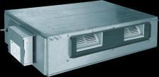
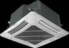
6 1.2 Indoor Unit Type Model Name Nominal Capacity Cooling/Heating (kw) Power Supply (V, Ph, Hz) Appearance CH-ID09NK4 2.7/2.9 CH-ID12NK4 3.5/ V~ 50Hz CH-ID18NK4 5.0/5.6 Duct Type CH-ID24NK4 7.0/8.0 CH-ID30NK4 8.3/9.2 CH-ID36NK4 10.0/12.0 CH-ID42NK4 11.5/ V~ 50Hz V~ 50Hz CH-ID48NK4 14.0/15.5 CH-ID60NK4 16.0/ V~ 50Hz CH-IC12NK4 3.5/3.8 CH-IC18NK4 5.0/5.5 Cassette Type CH-IC24NK4 7.0/8.0 CH-IC30NK4 8.3/9.2 CH-IC36NK4 10.0/ V~ 50Hz CH-IC42NK4 11.0/12.5 Ceiling Type CH-IC48NK4 14.0/16.0 CH-IC60NK4 16.0/17.0 CH-IF09NK4 2.7/2.9 CH-IF12NK4 3.5/3.8 CH-IF18NK4 5.0/5.6 CH-IF24NK4 7.0/8.0 CH-IF30NK4 8.5/9.2 CH-IF36NK4 10.0/12.0 CH-IF42NK4 11.5/ V~ 50Hz V~ 50Hz V~ 50Hz CH-IF48NK4 14.0/16.0 CH-IF60NK4 16.0/ V~ 50Hz Note:1 Ton =12000Btu/h = 3.517kW NOTES: The universal outdoor units means that the customer can choose any of three kind of indoor unit to match the outdoor unit without any change with it. 4
7 2 PRODUCT DATA 2.1 Product Data of Indoor Unit Duct Type Indoor unit CH-ID09NK4 CH-ID12NK4 CH-ID18NK4 CH-ID24NK4 Model Outdoor unit CH-IU09NK4 CH-IU12NK4 CH-IU18NK4 CH-IU24NK4 Capacity Power Input Cooling Capacity kw 2.7( ) 3.5( ) 5.0( ) 7.0( ) Heating Capacity kw 2.9( ) 3.8( ) 5.6( ) 8.0( ) PdesignH kw Cooling kw 0.84( ) 1.17( ) 1.60( ) 2.18( ) Heating kw 0.80( ) 1.05( ) 1.58( ) 2.21( ) Design load - Average SEER / SCOP W/W 5.6/ / / /4.0 Energy Rate(Cooling / Heating) - A+/A A+/A+ A+/A A++/A+ Fan Indoor Unit CH-ID09NK4 CH-ID12NK4 CH-ID18NK4 CH-ID24NK4 Power Supply V~ 50Hz Heat Exchange - Cross Fin Coil Cross Fin Coil Cross Fin Coil Cross Fin Coil Drive - direct direct direct direct Motor Output kw Air Flow m 3 /h Rated Ext. Static Pressure Pa Ext. Static Pressure Range Pa 0~30 0~30 0~30 0~100 Sound Pressure Level(H/M/L) db(a) 36/35/33/28 37/36/34/28 40/39/36/28 47/46/44/40 Air Filter Standard washable synthetic Drain mm Φ Φ Φ Φ Outline Dimensions (W H D) mm Compressor Refrigerant Net Weight kg Outdoor Unit CH-IU09NK4 CH-IU12NK4 CH-IU18NK4 CH-IU24NK4 Power Supply V~ 50Hz Heat Exchange - Cross Fin Coil Type - Rotary Rotary Rotary Rotary Power Input W Control - Electronic Expansion Valve Charge kg Outline Dimensions (W H D) mm Piping Connections Net Weight kg Liquid Inch Φ1/4 Φ1/4 Φ1/4 Φ3/8 Gas Inch Φ3/8 Φ3/8 Φ1/2 Φ5/8 Max. Length m Max. Height m
8 Indoor unit CH-ID30NK4 CH-ID36NK4 CH-ID36NK4 CH-ID42NK4 Model Outdoor unit CH-IU30NK4 CH-IU36NK4 CH-IU36NM4 СH-IU42NM4 Capacity Power Input Cooling Capacity kw 8.3( ) 10.0( ) 10.0( ) 11.5( ) Heating Capacity kw 9.2( ) 12.0( ) 12.0( ) 13.5( ) PdesignH kw Cooling kw 2.67( ) 3.20( ) 3.20( ) 4.00( ) Heating kw 2.57( ) 3.40( ) 3.40( ) 3.90( ) Design load - Average SEER / SCOP W/W 6.1/ / / /3.8 Energy Rate(Cooling / Heating) - A++/A+ A+/A+ A/A+ A+/A Fan Indoor Unit CH-ID30NK4 CH-ID36NK4 CH-ID36NK4 CH-ID42NK4 Power Supply V~ 50Hz Heat Exchange - Cross Fin Coil Cross Fin Coil Cross Fin Coil Cross Fin Coil Drive - direct direct direct direct Motor Output kw Air Flow m 3 /h Rated Ext. Static Pressure Pa Ext. Static Pressure Range Pa 0~100 0~150 0~150 0~150 Sound Pressure Level(H/M/L) db(a) 47/46/44/40 53/52/48/44 53/52/48/44 53/52/48/44 Air Filter - Standard washable synthetic Drain Piping mm Φ Φ Φ Φ Outline Dimensions (W H D) mm Compressor Refrigerant Net Weight kg Outdoor Unit CH-IU30NK4 CH-IU36NK4 CH-IU36NM4 CH-IU42NM4 Power Supply V~ 50Hz Heat Exchange - Cross Fin Coil V 3N~ 50Hz V~ 50Hz Type - Rotary Rotary Rotary Rotary Power Input W Control - Electronic Expansion Valve Charge kg Outline Dimensions (W H D) mm Piping Connections Net Weight kg Liquid Inch Φ3/8 Φ3/8 Φ3/8 Φ3/8 Gas Inch Φ5/8 Φ5/8 Φ5/8 Φ5/8 Max. Length m Max. Height m
9 Indoor unit CH-ID42NK4 CH-ID48NK4 CH-ID48NK4 CH-ID60NK4 Model Outdoor unit CH-IU42NM4 CH-IU48NK4 CH-IU48NM4 CH-IU60NM4 Cooling Capacity kw 11.5( ) 14.0( ) 14.0( ) 16.0(7.4~16.5) Capacity Heating Capacity kw 13.5( ) 15.5( ) 15.5( ) 16.5(6.2~18.5) PdesignH kw Power Input Cooling kw 4.00( ) 4.70( ) 4.70( ) 5.70( ) Heating kw 3.90( ) 4.40( ) 4.40( ) 4.60( ) Design load Average SEER / SCOP W/W 5.6/ / / /3.8 Energy Rate(Cooling / Heating) - A+/A+ A++/A A+/A A+/A Indoor Unit CH-ID42NK4 CH-ID48NK4 CH-ID48NK4 CH-ID60NK4 Power Supply V~ 50Hz Heat Exchange - Cross Fin Coil Cross Fin Coil Cross Fin Coil Cross Fin Coil Drive - direct direct direct direct Motor Output kw Fan Air Flow m 3 /h Rated Ext. Static Pressure Pa Ext. Static Pressure Range Pa 0~150 0~150 0~150 0~150 Sound Pressure Level(H/M/L) db(a) 53/52/48/44 55/53/49/45 55/53/49/45 56/55/51/46 Air Filter - Standard washable synthetic Drain Piping mm Φ Φ Φ Φ Outline Dimensions (W H D) mm Net Weight kg Outdoor Unit CH-IU42NM4 CH-IU48NK4 CH-IU48NM4 CH-IU60NM4 Power Supply V 3N~ 50Hz V~ 50Hz V 3N~ 50Hz Heat Exchange - Cross Fin Coil Compressor Refrigerant Type - Rotary Rotary Rotary Rotary Power Input W Control - Electronic Expansion Valve Charge kg Outline Dimensions (W H D) mm Net Weight kg Liquid Inch Φ3/8 Φ3/8 Φ3/8 Φ3/8 Piping Connections Gas Inch Φ5/8 Φ5/8 Φ5/8 Φ3/4 Max. Length m Max. Height m
10 3.1.2 Cassette Type Model Indoor unit CH-IC12NK4 CH-IC18NK4 CH-IC24NK4 Outdoor unit CH-IU12NK4 CH-IU18NK4 CH-IU24NK4 Capacity Power Input Cooling Capacity kw 3.5( ) 5.0( ) 7.0( ) Heating Capacity kw 3.8( ) 5.5( ) 8.0( ) PdesignH kw Cooling kw 1.09( ) 1.55( ) 2.18( ) Heating kw 1.05( ) 1.64( ) 2.21( ) Design load - Average SEER / SCOP W/W 5.6/ / /4.0 Energy Rate(Cooling / Heating) - A+/A+ A+/A A++/A+ Fan Indoor Unit CH-IC12NK4 CH-IC18NK4 CH-IC24NK4 Power Supply V~50Hz Heat Exchange - Cross Fin Coil Cross Fin Coil Cross Fin Coil Drive - direct direct direct Motor Output kw Air Flow m 3 /h Sound Pressure Level(H/M/L) db(a) 46/45/43/37 47/46/44/37 47/46/42/38 Air Filter - Standard washable synthetic Drain Piping mm Φ Φ Φ Outline Dimensions (W H D) mm Compressor Refrigerant Net Weight kg Outdoor Unit CH-IU12NK4 CH-IU18NK4 CH-IU24NK4 Power Supply V~50Hz Heat Exchange - Cross Fin Coil Type - Rotary Rotary Rotary Power Input W Control - Electronic Expansion Valve Charge kg Outline Dimensions (W H D) mm Piping Connections Net Weight kg Liquid Inch Φ1/4 Φ1/4 Φ3/8 Gas Inch Φ3/8 Φ1/2 Φ5/8 Max. Length m Max. Height m
11 Indoor unit CH-IC30NK4 CH-IC36NK4 CH-IC36NK4 CH-IC42NK4 Model Outdoor unit CH-IU30NK4 CH-IU36NK4 CH-IU36NM4 CH-IU42NM4 Capacity Power Input Cooling Capacity kw 8.3( ) 10.0( ) 10.0( ) 11.0( ) Heating Capacity kw 9.2( ) 12.0( ) 12.0( ) 12.5( ) PdesignH kw Cooling kw 2.67( ) 3.20( ) 3.20( ) 3.90( ) Heating kw 2.57( ) 3.50( ) 3.50( ) 3.80( ) Design load - Average SEER / SCOP W/W 6.1/ / / /4.0 Energy Rate(Cooling / Heating) - A++/A+ A++/A+ A++/A+ A+/A+ Fan Indoor Unit CH-IC30NK4 CH-IC36NK4 CH-IC36NK4 CH-IC42NK4 Power Supply V~ 50Hz Heat Exchange - Cross Fin Coil Cross Fin Coil Cross Fin Coil Cross Fin Coil Drive - direct direct direct direct Motor Output kw Air Flow m 3 /h Sound Pressure Level(H/M/L) db(a) 49/48/45/40 51/49/46/43 51/49/46/43 51/49/46/43 Air Filter - Standard washable synthetic Drain Piping mm Φ Φ Φ Φ Outline Dimensions (W H D) mm Compressor Refrigerant Net Weight kg Outdoor Unit CH-IU30NK4 CH-IU36NK4 CH-IU36NM4 CH-IU42NM4 Power Supply V~ 50Hz Heat Exchange - Cross Fin Coil V 3N~ 50Hz V~ 50Hz Type - Rotary Rotary Rotary Rotary Power Input W Control - Electronic Expansion Valve Charge kg Outline Dimensions (W H D) mm Piping Connections Net Weight kg Liquid Inch Φ3/8 Φ3/8 Φ3/8 Φ3/8 Gas Inch Φ5/8 Φ5/8 Φ5/8 Φ5/8 Max. Length m Max. Height m
12 Indoor unit CH-IC42NK4 CH-IC48NK4 CH-IC48NK4 CH-IC60NK4 Model Outdoor unit CH-IU42NM4 CH-IU48NK4 CH-IU48NM4 CH-IU60NM4 Capacity Power Input Cooling Capacity kw 11.0( ) 14.0( ) 14.0( ) 16.0(7.4~16.5) Heating Capacity kw 12.5( ) 16.0( ) 16.0( ) 16.5(6.2~18.5) Design load PdesignH kw Cooling kw 3.90( ) 4.60( ) 4.60( ) 5.70( ) Heating kw 3.80( ) 4.50( ) 4.50( ) 4.60( ) Average SEER / SCOP W/W 6.1/ / / /4.0 Energy Rate(Cooling / Heating) - A++/A+ A++/ A+/A A++/A+ Fan Indoor Unit CH-IC42NK4 CH-IC48NK4 CH-IC48NK4 CH-IC60NK4 Power Supply V~ 50Hz Heat Exchange - Cross Fin Coil Cross Fin Coil Cross Fin Coil Cross Fin Coil Drive - direct direct direct direct Motor Output kw Air Flow m 3 /h Sound Pressure Level(H/M/L) db(a) 51/49/46/43 53/52/47/41 53/52/47/41 54/53/47/41 Air Filter - Standard washable synthetic Drain Piping mm Φ Φ Φ Φ Outline Dimensions (W H D) mm Compressor Refrigerant Net Weight kg Outdoor Unit CH-IU42NM4 CH-IU48NK4 CH-IU48NM4 CH-IU60NM4 Power Supply V 3N~ 50Hz V~ 50Hz Heat Exchange - Cross Fin Coil V 3N~ 50Hz Type - Rotary Rotary Rotary Rotary Power Input W Control - Electronic Expansion Valve Charge kg Outline Dimensions (W H D) mm Piping Connections Net Weight kg Liquid Inch Φ3/8 Φ3/8 Φ3/8 Φ3/8 Gas Inch Φ5/8 Φ5/8 Φ5/8 Φ3/4 Max. Length m Max. Height m
13 3.1.3 Floor-ceiling Type Indoor unit CH-IF09NK4 CH-IF12NK4 CH-IF18NK4 CH-IF24NK4 Model Outdoor unit CH-IU09NK4 CH-IU12NK4 CH-IU18NK4 CH-IU24NK4 Capacity Power Input Cooling Capacity kw 2.7( ) 3.5( ) 5.0( ) 7.0( ) Heating Capacity kw 2.9( ) 3.8( ) 5.6( ) 8.0( ) PdesignH kw Cooling kw 0.84( ) 1.09( ) 1.55( ) 2.18( ) Heating kw 0.80( ) 1.05( ) 1.55( ) 2.21( ) Design load - Average SEER / SCOP W/W 6.1/ / / /4.0 Energy Rate(Cooling / Heating) - A++/A A++/A+ A++/A+ A+/A+ Fan Indoor Unit CH-IF09NK4 CH-IF12NK4 CH-IF18NK4 CH-IF24NK4 Power Supply V~ 50Hz Heat Exchange - Cross Fin Coil Cross Fin Coil Cross Fin Coil Cross Fin Coil Drive - direct direct direct direct Motor Output kw Air Flow m 3 /h Sound Pressure Level(H/M/L) db(a) 37/35/32/28 40/38/35/31 44/42/38/32 49/48/46/40 Air Filter - Standard washable synthetic Drain Piping mm Φ Φ Φ Φ Outline Dimensions (W H D) mm Compressor Refrigerant Net Weight kg Outdoor Unit CH-IU09NK4 CH-IU12NK4 CH-IU18NK4 CH-IU24NK4 Power Supply V~ 50Hz Heat Exchange - Cross Fin Coil Type - Rotary Rotary Rotary Rotary Power Input W Control - Electronic Expansion Valve Charge kg Outline Dimensions (W H D) mm Piping Connections Net Weight kg Liquid Inch Φ1/4 Φ1/4 Φ1/4 Φ3/8 Gas Inch Φ3/8 Φ3/8 Φ1/2 Φ5/8 Max. Length m Max. Height m
14 Indoor unit CH-IF30NK4 CH-IF36NK4 CH-IF36NK4 CH-IF42NK4 Model Outdoor unit CH-IU30NK4 CH-IU36NK4 CH-IU36NM4 CH-IU42NM4 Capacity Power Input Cooling Capacity kw 8.5( ) 10.0( ) 10.0( ) 11.5( ) Heating Capacity kw 9.2( ) 12.0( ) 12.0( ) 13.5( ) PdesignH kw Cooling kw 2.67( ) 3.20( ) 3.20( ) 3.90( ) Heating kw 2.57( ) 3.40( ) 3.40( ) 3.70( ) Design load - Average SEER / SCOP W/W 6.1/ / / /4.0 Energy Rate(Cooling / Heating) - A++/A+ A++/A+ A++/A+ A++/A+ Fan Indoor Unit CH-IF30NK4 CH-IF36NK4 CH-IF36NK4 CH-IF42NK4 Power Supply V~ 50Hz Heat Exchange - Cross Fin Coil Cross Fin Coil Cross Fin Coil Cross Fin Coil Drive - direct direct direct direct Motor Output kw Air Flow m 3 /h Sound Pressure Level(H/M/L) db(a) 49/46/44/38 54/53/51/46 54/53/51/46 55/54/52/47 Air Filter - Standard washable synthetic Drain Piping mm Φ Φ Φ Φ Outline Dimensions (W H D) mm Compressor Refrigerant Net Weight kg Outdoor Unit CH-IU30NK4 CH-IU36NK4 CH-IU36NM4 CH-IU42NM4 Power Supply V~ 50Hz Heat Exchange - Cross Fin Coil V 3N~ 50Hz V~ 50Hz Type - Rotary Rotary Rotary Rotary Power Input W Control - Electronic Expansion Valve Charge kg Outline Dimensions (W H D) mm Piping Connections Net Weight kg Liquid Inch Φ3/8 Φ3/8 Φ3/8 Φ3/8 Gas Inch Φ5/8 Φ5/8 Φ5/8 Φ5/8 Max. Length m Max. Height m
15 Indoor unit CH-IF42NK4 CH-IF48NK4 CH-IF48NK4 CH-IF60NK4 Model Outdoor unit CH-IU42NM4 CH-IU48NK4 CH-IU48NM4 CH-IU60NM4 Capacity Power Input Cooling Capacity kw 11.5( ) 14.0( ) 14.0( ) 16.0(7.4~16.5) Heating Capacity kw 13.5( ) 16.0( ) 16.0( ) 16.5(6.2~18.5) PdesignH kw Cooling kw 3.90( ) 4.80( ) 4.80( ) 5.70( ) Heating kw 3.70( ) 4.30( ) 4.30( ) 4.60( ) Design load - Average SEER / SCOP W/W 5.6/ / / /4.0 Energy Rate(Cooling / Heating) - A+/A+ A+/A A+/A+ A/A+ Fan Indoor Unit CH-IF42NK4 CH-IF48NK4 CH-IF48NK4 CH-IF60NK4 Power Supply V~ 50Hz Heat Exchange - Cross Fin Coil Cross Fin Coil Cross Fin Coil Cross Fin Coil Drive - direct direct direct direct Motor Output kw Air Flow m 3 /h Sound Pressure Level(H/M/L) db(a) 55/54/52/47 57/55/50/46 57/55/50/46 58/56/51/46 Air Filter - Standard washable synthetic Drain Piping mm Φ Φ Φ Φ Outline Dimensions (W H D) mm Compressor Refrigerant Net Weight kg Outdoor Unit CH-IU42NM4 CH-IU48NK4 CH-IU48NM4 CH-IU60NM4 Power Supply V 3N~ 50Hz V~ 50Hz Heat Exchange - Cross Fin Coil V 3N~ 50Hz Type - Rotary Rotary Rotary Rotary Power Input W Control - Electronic Expansion Valve Charge kg Outline Dimensions (W H D) mm Piping Connections Net Weight kg Liquid Inch Φ3/8 Φ3/8 Φ3/8 Φ3/8 Gas Inch Φ5/8 Φ5/8 Φ5/8 Φ3/4 Max. Length m Max. Height m
16 Note: Nominal capacities are based on the follow conditions. Mode Indoor Outdoor Cooling Heating DB:27(80.6) WB:19(66.2) DB:20(68) WB:--(--) DB:35(95) WB:24(75.2) DB:7(44.6) WB:6(42.8) Piping Length 09K-42K 5m 48K-60K 7.5m The air volume is measured at the relevant standard external static pressure. Noise is tested in the semianechoic room, so it should be slightly higher in the actual operation due to environmental change. 3.2 Operation Range Mode Range of Outdoor Temperature Cooling Heating Electrical Data Outdoor unit Table Electrical Data of Outdoor Unit Model Power Supply Compressor Fan Motor Qty. RLA FLA Fuse/Breaker Capacity Min. Power Supply Cord V/Ph/Hz A A A mm 2 CH-IU09NK4 220,1, < CH-IU12NK4 220,1, < CH-IU18NK4 220,1, < CH-IU24NK4 220,1, < CH-IU30NK4 220,1, < CH-IU36NK4 220,1, < CH-IU42NK4 220,1, < CH-IU48NK4 220,1, < CH-IU36NM4 380,3, < CH-IU42NM4 380,3, < CH-IU48NM4 380,3, < CH-IU60NM4 380,3, <
17 3.3.2 Indoor unit Model Table Electrical Data of Indoor Unit Power Fan Motor Fuse/Breaker Supply FLA Capacity Min. Power Supply Cord V/Ph/Hz A A mm 2 CH-ID09NK4 220,1,50 <1 5/6 1.0 CH-ID12NK4 220,1,50 <1 5/6 1.0 CH-ID18NK4 220,1,50 <1 5/6 1.0 CH-ID24NK4 220,1,50 <1 5/6 1.0 CH-ID30NK4 220,1,50 <1 5/6 1.0 CH-ID36NK4 220,1,50 <1 5/6 1.0 CH-ID42NK4 220,1,50 <1 5/6 1.0 CH-ID48NK4 220,1,50 <1 5/6 1.0 CH-ID60NK4 220,1,50 <1 5/6 1.0 CH-IC12NK4 220,1,50 <1 5/6 1.0 CH-IC18NK4 220,1,50 <1 5/6 1.0 CH-IC24NK4 220,1,50 <1 5/6 1.0 CH-IC30NK4 220,1,50 <1 5/6 1.0 CH-IC36NK4 220,1,50 <1 5/6 1.0 CH-IC42NK4 220,1,50 <1 5/6 1.0 CH-IC48NK4 220,1,50 <1 5/6 1.0 CH-IC60NK4 220,1,50 <1 5/6 1.0 CH-IF09NK4 220,1,50 <1 5/6 1.0 CH-IF12NK4 220,1,50 <1 5/6 1.0 CH-IF18NK4 220,1,50 <1 5/6 1.0 CH-IF24NK4 220,1,50 <1 5/6 1.0 CH-IF30NK4 220,1,50 <1 5/6 1.0 CH-IF36NK4 220,1,50 <1 5/6 1.0 CH-IF42NK4 220,1,50 <1 5/6 1.0 CH-IF48NK4 220,1,50 <1 5/6 1.0 CH-IF60NK4 220,1,50 <1 5/6 1.0 Notes: RLA: Rated load amperes LRA: Locked rotor amperes FLA: Full load current 1. Install the disconnect device with a contact gap of at least 3mm in all poles nearby the units (Both indoor unit and outdoor unit).the appliance must be positioned so that the plug is accessible. 2. The specifications of the breaker and power cable listed in the table above are determined based on the maximum power (maximum amps) of the unit. 3. The specifications of the power cable listed in the table above are applied to the conduit-guarded multi-wire copper cable (like, YJV copper cable, consisting of PE insulated wires and a PVC 15
18 cable jacket) used at 40 С and resistible to 90 С (see IEC ). If the working condition changes, they should be modified according to the related national standard. 4. The specifications of the breaker listed in the table above are applied to the breaker with the working temperature at 40 С. If the working condition changes, they should be modified according to the related national standard. 4 PIPING DIAGRAM 16
19 CONTROL 17

20 CONTROL 1 OPERATION FLOWCHART 1.1 Cooling/Dry Operation C&H NORDIC Commercial 4 Service Manual 18
21 1.2 Heating Operation 19


22 2 WIRELESS REMOTE CONTROLLER 2.1 Operation and Display View Table Operation instruction of wireless remote controller No. Name Function Description Signal transmitter ON/OFF button MODE button Signal transmitter Press this button and the unit will be turned on; press it once more and the unit will be turned off. When turning off the unit, the Sleep function will be canceled, but the presetting time is still remained. By pressing this button, Auto, Cool, Dry, Fan, Heat mode can be selected circularly. Auto mode is default after power on. Under the Auto mode, the setting temperature will not be displayed; Under the Heat mode, the initial value is 28 C (82 F); under other modes, the initial value is 25 C (77 F). AUTO; COOL; DRY; FAN; HEAT (only for cooling and heating unit) 20

23 - button + button Preset temperature can be decreased by pressing this button. Pressing and holding this button for more than 2 seconds can make the temperature changed quickly until release this button and then transmit this order. The temperature adjustment is unavailable under the Auto mode, but the order can be sent by pressing this button. Centigrade setting range: 16-30; Fahrenheit scale setting range Preset temperature can be increased by pressing this button. Pressing and holding this button for more than 2 seconds can make the temperature changed quickly until release the button and then transmit this order. The temperature adjustment is unavailable under the Auto mode, but the order can be sent by pressing this button. Centigrade setting range: 16-30; Fahrenheit scale setting range By pressing this button, Auto, Low, Middle, High speed can be circularly selected. After power on, Auto fan speed is default. FAN button Low speed Middle speed High speed Note: Under the DRY mode, the fan will be kept running at the low speed and the fan speed isn't adjustable. Press this button to set up the swing angle, which circularly changes as below: SWING UP/DOW N button When the guide louver starts to swing up and down, if SWING functions are canceled, the air guide louver will stop and remains at the current position. Indicates the guide louver swings up and down among those five directions.(simplified SWING function applicable for some Fan Coil Units: When the wireless remote controller is energized initially with the unit under the OFF status, it should be set by pressing the + button and the SWING button simultaneously, with the symbol blinking twice. Then, after the unit is turned on, this function can be activated by pressing the SWING button, with the displayed symbol indicating swing function is on and without this displayed symbol indicating swing function is off.) CLOCK button TIMER ON button X-FAN button TEMP button By pressing this button, the clock is allowed to be set, with blinking, and then press the +/- button to adjust the clock within 5 seconds. If the +/-button is pressed down constantly for more than 2 seconds, the clock setting will be increased or decreased 10 minutes every 0.5 seconds. After that, another press on the CLOCK button accepts the setting. 12:00 is the default, when the wireless remote controller is energized. When TIMER ON is activated, ON will blink while the symbol will disappear. Within 5 seconds it is allowed to set the ON time by pressing the +/- button. Each press will make the time increase or decrease one minute. Besides, the time can also be set by pressing the +/- button constantly. That is, in the early 2.5 seconds, the time will increase/decrease quickly per single minute, and in the late 2.5, the time will increase/decrease per ten minutes. After the desired time value is set, press TIENE ON again to conform the setting within five seconds. After that, another press on TIMER ON will cancel the setting. Prior to this setting, the clock shall be set to the actual time. Pressing this button can activate or deactivate the X-FAN function. In Cool or Dry mode, by pressing this button, if " " is displayed, it indicates the X-FAN function is activated. By repressing this button, if " " disappears, it indicates the X-FAN function is deactivated. After energization, X-FAN OFF is defaulted. If the unit is turned off, X-FAN can be deactivated but can't be activated. By pressing this button it is allowed to select displaying the indoor setting temperature or the indoor ambient temperature. Indoor setting temperature is default after the indoor unit is energized initially. By pressing the TEMP button, when the temperature symbol is displayed, the indoor displayer will show the indoor setting temperature; when is displayed, it will show the indoor ambient temperature; when is invalidation, If current displays indoor ambient temperature, if received the other remote control signal, it will display presetting temperature, 5s later, will back to display the ambient temperature. (This function is applicable to partial of models) 21

. By pressing this button, Sleep On and Sleep Off can be selected. After powered on, Sleep Off is defaulted.")
24 TIMER OFF button TURBO button SLEEP button LIGHT button By pressing this button it is available to go to the TIMER OFF setting state with the same setting method as that of the TIMER ON, in which case the OFF symbol blinks. In the Cool or Heat mode, pressing this button can activate or deactivate the TURBO function. When the TURBO function is activated, its symbol will be displayed; when the running mode or the fan speed is changed, this function will be canceled automatically. (This function is applicable to partial of models). By pressing this button, Sleep On and Sleep Off can be selected. After powered on, Sleep Off is defaulted. Once the unit is turned off, the Sleep function is canceled. When Sleep is set to on, the symbol of SLEEP will display. Under the Fan and Auto modes, this function is not available. Press this button to select LIGHT on or off in the displayer. When the LIGHT is set to on, the icon will be displayed and the indicating light in the displayer will be on. When the LIGHT is set to off, the icon will be disappeared and the indicating light in the displayer will be off. 3 WIRED CONTROLLER 3.1 Display View Figure Appearance of wired controller Figure LCD display of wired controller 22
25 Table Instruction to LCD Display No. Icons Introduction 1 Left and right swing function 2 Up and down swing function 3 Air exchange function 4 Sleep function 5 Auto mode 6 COOL mode 7 DRY mode 8 FAN mode 9 HEAT mode 10 Health function 1 1 I-Demand function 12 Vacation function 13 Status display of master and slave wired controller 14 Shield function The button operation, temperature setting, "On/Off" operation, "Mode" setting, and "Save" setting are disabled. 15 Fan speed 16 Memory function The unit will resume the original setting state after power recovery. 17 Turbo function 18 Energy-saving function 19 Ambient/setting temperature 20 Electric heater 21 Blow function 22 Defrosting function 23 Filter cleaning 24 Timer Setting 25 Keycard control / Detected status sensed by human body 26 Quiet function 27 Lock function 23
Function selection and canceling; (2)Press it for 5s to view the ambient temperature; press Mode button to select viewing outdoor ambient temperature or")
 Setting of air function level; (4) Setting of energy-saving temperature; (5) Setting of cleaning class. 3 Fan Setting of high/medium high/medium/medium low/low/auto fan speed.")
26 3.2 Operation View Silk Screen of Buttons Figure Silk screen of buttons Instruction to Function of Buttons Table Instruction to buttons of wired controller No. Description Functions 1 Enter/Cancel 2 6 (1)Function selection and canceling; (2)Press it for 5s to view the ambient temperature; press Mode button to select viewing outdoor ambient temperature or indoor ambient temperature. (1) Running temperature setting range of indoor unit: ; (2) Timer setting range: hr; (3) Setting of air function level; (4) Setting of energy-saving temperature; (5) Setting of cleaning class. 3 Fan Setting of high/medium high/medium/medium low/low/auto fan speed. 4 Mode Setting of auto/cooling/heating/fan/dry mode of indoor unit. 5 Function Switch over among these functions of swing/air/sleep/health/ I-Demand/out/turbo/save/e-heater/X-fan/clean/quiet. 7 Timer Timer setting. 8 On/Off Turn on/off indoor unit. 4 Mode and 2 2 and 6 4 Mode and 5 Function 5 Function and 7 Timer 4 Mode and 6 5 Function and 6 1 Enter/Cancel and 4 Mode Memory function Lock Enquiry and setting of address of wired controller Setting of project parameters (More details please refer to the Notes) Switch between Fahrenheit and Centigrade Viewing historical malfunction Setting of master and slave wired controller Press Mode and buttons at the same time for 5s under off state of the unit to enter/cancel memory function (If memory function is set, indoor unit will resume original setting state after power failure and then power recovery. If not, indoor unit is defaulted to be off after power recovery. Ex-factory setting of memory function is on). Upon startup of the unit without malfunction or under off state of the unit, press and buttons at the same time for 5s to enter lock state. In this case, any other buttons won t respond when pressing. Repress and buttons for 5s to quit lock state. Under off state of the unit, press Mode and Function buttons at the same time for 5s to set the address. (More details please refer to project debugging) Under off state of the unit, press Function and Timer buttons at the same time for 5s to go to the debugging menu. Press Mode button to adjust the setting items and press or buttons to set the actual value. Under off state of the unit, press Mode and buttons at the same time for 5s to switch between Fahrenheit and Centigrade. Continuously press Function and buttons for 5s to view historical malfunction. Then press and buttons to adjust displayed contents. The timer displaying position displays the sequence of malfunction and the detailed error code. The 5 th displayed malfunction is the last malfunction. Under off state of the unit, press Enter/Cancel and Mode buttons at the same time for 5s to set master and slave wired controller. Press or button to adjust. (More details please refer to project debugging) 24
27 Notes: The following functions can be set through Function and Timer buttons: setting of ambient temperature sensor, selecting three speeds in high speed and three speeds in low speed of indoor fan motor, display setting of freeze protection error code, setting of cold air prevention and hot air hot prevention function, setting of refrigerant-lacking protection function, selecting of blowing residual heat of indoor unit, selecting of compressor electric heater mode, selecting of low-power consumption mode, selecting door control function, selecting human sensitive function, long-distance monitoring, temperature compensation value at the air return port Setting of Wired Controller s Address Enquiry and Setting of Wired Controller s Address Under off state of the unit, press Function and Mode buttons at the same time for 5s to enter setting interface of wired controller s address. In this case, LCD displays address number. Then press or button to adjust address and then press Enter/Cancel button to confirm. The address setting is related to the setting of Debugging Function When the selection in is 00, address of centralized controller is to be set and the address setting range is 01~16; when the selection in is 01, address of long-distance monitor is to be set and the address setting range is 01~255. Enquiry and setting of wired controller s address is shown as Figure below: Figure Enquiry and setting of wired controller s address Setting of Master/Slave Wired Controller s Address Under off status of the unit, press Enter/Cancel and Mode buttons at the same time for 5s to go to 25

28 the enquiry and setting interface of master/slave wired controller. In this case, LCD displays wired controller s address (01 for master wired controller and 02 for slave wired controller). Press or button to adjust address of master/slave wired controller and then press Enter/Cancel button to confirm. If slave wired controller is set, the icon will be displayed. Note: If there is only one wired controller, it only can be set as the master; if there are two wired controllers, one should be the master and the other should be the slave. Setting of master/slave wired controller s address is shown as Figure below: Figure Enquiry and setting of master/slave wired controller s address 4 OPERATION INSTRUCTION OF SPECIAL FUNCTIONS 4.1 Setting of Filter Clean Reminder Function When unit is on, press Function button to switch to filter clean reminder function. The will blink and then enter setting of filter clean reminder function. Timer zone displays the set pollution level and you can press or button to adjust the level. Then press Enter/Cancel button to turn on this function. When filter clean reminder function is turned on, press Function button to switch to filter clean reminder function. The icon will blink and press or button to adjust timer zone to display 26 icon


 Medium pollution: the former digit in timer")

29 00. Then press Enter/Cancel button to cancel this function. Setting of filter clean reminder function is shown as Figure below: Figure Setting of filter clean reminder function When setting the filter clean reminder function, timer zone will display 2 digits, of which the former indicates the pollution dec&h of operating place and the latter indicates the accumulated operating time of indoor unit. There are 4 types of situations: (1) Clean Reminder is off (Timer zone shows 00 ; (2) Slight pollution: the former digit in timer zone shows 1 while the latter one shows 0, which indicates the accumulated operating time is 5500hr. Each time the latter digit increases 1, the accumulated operating time increases 500hr. When it reaches 9, it means the accumulated operating time is 10000hr; (3) Medium pollution: the former digit in timer zone shows 2 while the latter one shows 0, which indicates the accumulated operating time is 1400hr. Each time the latter digit increases 1, the accumulated operating time increases 400hr. When it reaches 9, it means the accumulated operating time is 5000hr; (4) Heavy pollution: the former digit in timer zone shows 3 while the latter one shows 0, which 27
30 indicates the accumulated operating time is 100hr. Each time the latter digit increases 1, the accumulated operating time increases 100hr. When it reaches 9, it means the accumulated operating time is 1000hr; The detailed pollution level and the corresponding time are as shown in Table below: Table Pollution level and corresponding time Accumulated Accumulated Accumulated Pollution Pollution Pollution operating time operating time operating time level level level (hour) (hour) (hour) If filter clean reminder function is turned on, the icon will be on. (1) If cleaning time is not reached, no mater the setting is changed or not, the accumulated operating time won t be recalculated when pressing Enter/Cancel button; (2) If cleaning time is reached, in unit on or off state, will blink every 0.5s for reminder. Press Function button to switch to icon and press and button to adjust the level. Then press Enter/Cancel button, so the accumulated operating time won t be cleared (If the adjusted level is higher than the present accumulated operating time, the icon won t blink any more; if the adjusted level is lower than the present accumulated operating time, the icon will go on blinking). (3) The only way to cancel filter clean reminder function is to press Function button to switch to filter clean reminder function. The icon will blink and press or button to adjust timer zone to display 00. In this case, the accumulated operating time will be cleared. 4.2 Low Temperature Drying Function Under dry mode and when set temperature is 16, continuously press button for twice and then the set temperature will be 12. In this case, the unit will enter low temperature drying function. When low temperature drying function is turned on, press button or Mode button to exit low temperature drying function. 4.3 Lock Function When unit is turned on normally or turned off, pressing and buttons at the same time for 5s will turn on Lock function. LCD will display. Pressing and buttons at the same time for 5s to turn off this function. When Lock function is turned on, any other buttons won t respond when pressing. The function can be memorized after power failure and then power recovery. 4.4 Memory Function Press Mode and buttons at the same time for 5s under off state of the unit to turn on or cancel memory function. If memory function is set, is displayed. If not, indoor unit is defaulted to be 28
31 off after power recovery. If memory function is set, indoor unit will resume original setting state after power failure and then power recovery. Note: If cut off power with 5s after memorized content is changed, the memorized content may be abnormal. Do not cut off power within 5s after memorized content is changed. 4.5 Door Control Function/Human Sensitive Function Door control function or human sensitive function can be selected (More details please refer to Debugging Function). These two functions can t be turned on at the same time. When door control function is selected, the wired controller will work when the room card is inserted and stop working when the room card is not inserted; when human sensitive function is selected, the wired controller will work when it senses there is somebody in the room and stop working when it senses there is nobody in the room. When the door control function senses the room card is not inserted or human sensitive function senses there is nobody in the room, the wired controller will display icon. Note: 1. In long-distance monitoring or centralized control, no matter the room card is inserted or not, the ON/OFF of unit can be controlled. If long-distance monitoring or centralized control information is received when the room card is not inserted, icon is cleared. When the card is reinserted, door control function is judged to be turned on. If long-distance monitoring or centralized control information is received when the room card is inserted, it will keep the original status. 2. The unit can not be controlled by buttons when the card is not inserted. 3. When door control function and human sensitive function have been set at the same time, it is defaulted that door control function is valid and human sensitive function is invalid. 4.6 Switch between Fahrenheit and Centigrade Under off state of the unit, press Mode and buttons at the same time for 5s to switch between Fahrenheit and Centigrade. 4.7 Enquiry of Ambient Temperature Under off or on state of the unit, press it for 5s to view the ambient temperature. In this case, timer zone displays ambient temperature type 01 or 02. Ambient temperature zone displays the corresponding temperature of that type. 01 stands for outdoor ambient temperature and 02 stands for the indoor ambient temperature after compensation. Press Mode button to switch between 01 and 02. Pressing other buttons except Mode button or receiving remote control signal will exit enquiry state. If there is no operation within 20s will also exit enquiry state. Note: 1. If the unit is not connected to outdoor ambient temperature sensor, display of outdoor ambient temperature will be shielding after energizing for 12hr. 2. If there is malfunction of outdoor ambient temperature sensor, display of outdoor ambient temperature will be shielding after energizing for 12hr. 4.8 Enquiry of Historical Malfunction Under off or on state of the unit, continuously press Function and buttons for 5s to view historical malfunction. 29
32 In enquiry state, set temperature displaying zone displays 00. Press and buttons to view the 5 malfunctions happened recently. The timer displaying position displays the detailed error code. The 5th displayed malfunction is the last malfunction. 4.9 Debugging Function Under off state of the unit, press Function and Timer buttons at the same time for 5s to go to the debugging menu. Press Mode button to adjust the setting items and press or button to set the actual value Setting ambient temperature sensor (dual ambient temperature sensors function) Under debugging state, press Mode button to adjust to 00 in temperature displaying zone. Timer zone displays setting state and press or button to adjust. There are 3 selections: (1) The ambient temperature at air return is set as indoor ambient temperature (timer zone displays 01) (2) The temperature at wired controller is set as indoor ambient temperature (timer zone displays 02) (3) Select the temperature sensor at air return in cooling, dry and fan mode; select the temperature sensor at wired controller in heating and auto mode Selecting three speeds in high speed and three speeds in low speed of indoor fan motor Under debugging state, press Mode button to adjust to 01 in temperature displaying zone. Timer zone displays setting state and press or button to adjust. There are 2 selections: (1) Three speeds in low speed (LCD displays 01) (2) Three speeds in high speed (LCD displays 02) Three speeds in low speed include high, medium and low speeds; three speeds in high speed include super high, high and medium speed. Note: For this series, this function is invalid Displaying setting of freeze protection error code Under debugging state, press Mode button to adjust to 02 in temperature displaying zone. Timer zone displays setting state and press or button to adjust. There are 2 selections: (1) Displayed (LCD displays 01) (2) Not displayed (LCD displays 02) It is defaulted to be not displayed for export unit and be displayed for domestic unit Setting refrigerant lacking protection function Under debugging state, press Mode button to adjust to 04 in temperature displaying zone. Timer zone displays setting state and press or button to adjust. There are 2 selections: (1) With refrigerant lacking protection function (LCD displays 01) (2) Without refrigerant lacking protection function (LCD displays 02) Selecting blowing residual heating of indoor unit Under debugging state, press Mode button to adjust to 05 in temperature displaying zone. Timer zone displays setting state and press or button to adjust. There are 2 selections: (1) Mode 1 (LCD displays 00) 30
33 (2) Mode 2 (LCD displays 01) Note: Blowing residual heating of indoor unit Mode 1: Unit stops when reaching temperature point and indoor fan motor does not stop in cooling mode; after unit stops when reaching temperature point in heating mode, duct type unit and floor ceiling unit blow residual heat for 60s and then stop indoor unit, while cassette type unit always operates in low fan speed and blows residual heat for 60s when there is malfunction. Mode 2: After unit stops when reaching temperature point, the indoor fan motor stops operation with a 10s delay no matter in cooling mode or in heating mode Mode selecting of compressor electric heating belt Under debugging state, press Mode button to adjust to 06 in temperature displaying zone. Timer zone displays setting state and press or button to adjust. There are 2 selections: (1) Mode 1 (LCD displays 00) (2) Mode 2 (LCD displays 01) Note: Mode 1: Compressor electric heating belt starts when outdoor ambient temperature is below 35 and stops when outdoor ambient temperature is above 37. When outdoor ambient temperature is within 35 ~ 37, the belt will keep its previous operation state. Mode 1: Compressor electric heating belt starts when outdoor ambient temperature is below -2 and stops when outdoor ambient temperature is above 0. When outdoor ambient temperature is within -2 ~0, the belt will keep its previous operation state Selecting low-power consumption mode Under debugging state, press Mode button to adjust to 07 in temperature displaying zone. Timer zone displays setting state and press or button to adjust. There are 2 selections: (1) With low-power consumption mode (LCD displays 00) (2) Without low-power consumption mode (LCD displays 01) Selecting door control function Under debugging state, press Mode button to adjust to 08 in temperature displaying zone. Timer zone displays setting state and press or button to adjust. There are 2 selections: (1) Without door control function (LCD displays 00) (2) With door control function (LCD displays 01) Selecting human sensitive function Under debugging state, press Mode button to adjust to 09 in temperature displaying zone. Timer zone displays setting state and press or button to adjust. There are 2 selections: (1) Without human sensitive function (LCD displays 00) (2) With human sensitive function (LCD displays 00) Selecting long-distance monitoring or centralized controller Under debugging state, press Mode button to adjust to 10 in temperature displaying zone. Timer zone displays setting state and press or button to adjust. There are 2 selections: (1) Centralized controller (LCD displays 00) (2) Long-distance monitoring (LCD displays 01) Selecting fan mode of indoor fan motor 31
34 Under debugging state, press Mode button to adjust to 11 in temperature displaying zone. Timer zone displays setting state and press or button to adjust. There are 5selections: (1) P3 (LCD displays 03) (2) P4 (LCD displays 04) (3) P5 (LCD displays 05) (4) P6 (LCD displays 06) (5) P7 (LCD displays 07) Note: You can select P03, P04, P05, P06, P07 in fan mode of indoor fan motor, which means different fan mode combinations are corresponding to different static pressure. Ex-factory defaulted mode is P05. You can set the mode through wired controller. S01, S02, S03 S12, S13 means the rotation speed of indoor unit is from low to high. Table Combination relationship of P03, P04, P05, P06, P07 Static Super Medium Medium Quiet Quiet Quiet High Medium Low pressure high high low R1 R2 R13 speed speed speed selection speed speed speed speed speed speed P03 S09 S08 S07 S06 S05 S04 S03 S02 S01 P04 S10 S09 S08 S07 S06 S05 S04 S03 S02 P05 S11 S10 S09 S08 S07 S06 S05 S04 S03 P06 S12 S11 S10 S09 S08 S07 S06 S05 S04 P07 S13 S12 S11 S10 S09 S08 S07 S06 S Selecting compensation of temperature sensor at air return Under debugging state, press Mode button to adjust to 12 in temperature displaying zone. Timer zone displays setting state and press or button to adjust. There are 16 selections: (1) Compensate 0 (LCD displays 00) (2) Compensate 1 (LCD displays 01) (3) Compensate 2 (LCD displays 02) (4) Compensate 3 (LCD displays 03) (5) Compensate 4 (LCD displays 04) (6) Compensate 5 (LCD displays 05) (7) Compensate 6 (LCD displays 06) (8) Compensate 7 (LCD displays 07) (9) Compensate 8 (LCD displays 08) (10) Compensate 9 (LCD displays 09) (11) Compensate 10 (LCD displays 10) (12) Compensate 11 (LCD displays 11) (13) Compensate 12 (LCD displays 12) (14) Compensate 13 (LCD displays 13) (15) Compensate 14 (LCD displays 14) (16) Compensate 15 (LCD displays 15) Note: Indoor ambient temperature compensation can be set through wired controller (E.g. If 02 is selected; it indicates the compensation temperature is 2. If the indoor ambient temperature detected 32
35 by the temperature sensor at air return is 29, the ambient temperature after compensation is 29-2 =27 ). After finishing setting, press Enter/Cancel button to save and exit setting. After entering this interface, the system will exit this menu if there is no operation on the button within 20s. Normal off state interface will be displayed and present setting will not be saved. 5 INSTALLATION OF WIRED CONTROLLER 5.1 Standard Accessories Table Standard Accessories of Wired Controller Description Quantity Note Socket base box installed in the wall 1 No.1 in Figure Base plate of wired controller 1 No.2 in Figure Screw M No.3 in Figure Panel of wired controller 1 No.4 in Figure Figure Installation Position and Requirement (1) Prohibit installing the wired controller at the misty place or the place with direct sunlight. (2) Prohibit installing the wired controller at the place near high temperature objects or water-splashing places. (3) Prohibit installing the wired controller at the place where faces forward to the window, to avoid interference of another remote controller from neighborhood. (4) Cut off the power of heavy current wire in the installation hole of the wall. All power should be cut off during installation. (5) In order to avoid abnormal operation due to electromagnetic interference, etc., pay attention to the following notes during connecting wires: 1) Make sure the tie-in interface of communication wire is correct, otherwise it may lead to communication malfunction. 2) The signal wires and communication wires of wired controller should be separated from power cord and connection wire between indoor unit and outdoor unit. 3) If the air conditioner is installed at the strong electromagnetic interference place, signal wire and communication wire of wired controller must use shielding twisted wire. 33
.")
36 5.3 Installation of Wired Controller Firstly, the selection and connection way of wired controller s signal wire are as below: (1) Choose suitable signal wire: 2-core signal wire (wire diameter >=0.75mm, wire length<30m and the recommended length is 8m). (2) Make sure the power of indoor unit is cut off; fix the signal wire of wired controller on the wiring board for wired controller of indoor unit with screws; make sure the signal wire is solid. Then, the detailed installation procedures of wired controller are as shown in Figure 2-5-2: Figure Installation of wired controller Brief instructions of installation procedure: 1) Pull out the 2-core signal wire in the installation hole of the wall and then let this wire go through the hole at the back of wired controller s base plate. 2) Fix the base plate and installation hole of the wall together with screw M ) Fix the above mentioned 2-core signal wire on the copper insert X1 and X2 with the equipped screws of wired controller. 4) Fasten the wired controller s panel with its base plate together. 5.4 Removal of Wired Controller Figure Removal of wired controller 34
37 6 TROUBLESHOOTING 6.1 Display of Error Code Table Error Code List Error Code E1 E2 E3 E4 E6 E8 E9 F0 F1 F2 F3 F4 F5 C5 EE PF H3 H4 H5 H6 H7 HC L1 Lc Ld LF Lp U7 P0 P5 P6 P7 P8 P9 PA PC Pd PE PL PH PU PP ee Compressor high pressure protection Error Freeze protection Compressor low pressure protection, refrigerant lacking protection, refrigerant recycling mode Compressor high discharge temperature protection Communication malfunction Malfunction of indoor fan motor Full water protection Malfunction of indoor ambient temperature sensor Malfunction of evaporator temperature sensor Malfunction of condenser temperature sensor Malfunction of outdoor ambient temperature sensor Malfunction of discharge temperature sensor Malfunction wired controller temperature sensor Wong dial switch of capacity Malfunction of outdoor main control memory chip Malfunction of electric box sensor Compressor overload protection Overload protection IPM protection Malfunction of DC fan motor Drive desynchronizing protection pfc protection Malfunction of humidity sensor Start-up failure Compressor phase protection Power protection Models of indoor unit and outdoor unit do not match with each other Direction changing malfunction of 4-way valve Drive reset protection Overcurrent protection Communication malfunction between main control and drive Malfunction of drive module sensor High temperature protection of drive module Zero-cross protection AC current protection Malfunction of drive current Sensor connection protection Temperature excursion protection Low voltage protection of bus bar High voltage protection of bus bar Charging circuit malfunction Abnormity of input voltage Malfunction of outdoor drive memory chip 35


38 When there is a malfunction during operation, error will be displayed on the temperature displaying zone of LCD. When several malfunctions occur at the same time, these error codes will be displayed circularly. When there is a malfunction, please turn off the unit and ask the professional for maintenance. For example, E1 means high pressure protection during operation. Figure CENTRALIZED CONTROLLER 7.1 Smart Zone Controller Function The smart zone controller can directly control up to 16 sets of indoor units in a control network and is available to check the running status of any unit through the LCD, including running mode, timer, fan speed, centralized control and shielding setting etc Outline Drawing of Press Buttons Figure

39 7.1.3 Functions of Press Buttons Table Functions of Press Buttons No. Name Function Description 1 Mode It is used for the switchover among different modes. 2 Fan It is used to set the fan speed, high, medium, low or auto. 3 On/Off It is used to set the on/off status of the indoor unit Under the single/centralized control status: It is used to set the running temperature of the indoor unit with max.30 C anmin.16 C; 2. Under the timing setting status: It is used to set the timing period with max.24 hours and min.0 hour; 3. Under the clock setting status: it is used to set the hour (max.:23, min.: 0) and minute (max.:59, min.: 0) of the clock. 6 Mon 1/9 It is used for the switchover between unit 1 and unit 9; Under the timing or clock setting status, it indicates Monday. 7 Tue 2/10 8 Wed 3/11 9 Thu 4/12 10 Fri 5/13 11 Sat 6/14 12 Sun 7/15 It is used for the switchover between unit 2 and unit 10; Under the timing or clock setting status, it indicates Tuesday. It is used for the switchover between unit 3 and unit 11; Under the timing or clock setting status, it indicates Wednesday. It is used for the switchover between unit 4and unit 12; Under the timing or clock setting status, it indicates Thursday. It is used for the switchover between unit 5and unit 13; Under the timing or clock setting status, it indicates Friday. It is used for the switchover between unit 6 and unit 14; Under the timing or clock setting status, it indicates Saturday. It is used for the switchover between unit 7 and unit 15; Under the timing or clock setting status, it indicates Sunday. 13 8/16 It is used for the switchover between unit 8 and unit Timer/Time It is used to set the timing or on/off time of the selected indoor unit as well as to set the clock of the system. 15 Central It is used for the switchover between single and centralized control modes. 16 Shield It is used to deactivate some or all functions of a single or a group the indoor unit(s). 17 All on/off It is used to start/stop all indoor units LCD of the Controller Outline Drawing of the LCD Figure

40 Introduction to Symbols on the LCD Figure Table Introduction to the Symbols on the LCD No. Name Description 1 Fan speed It displays the fan speed of the indoor unit, high, medium, low and auto. 2 Running mode It displays the running mode of the indoor unit, auto, cool, dry, fan and heat. 3 System clock It displays the current time (hour and minute) in 24-hour time system and also the week day. 4 Shield It displays the shield status, ALL, TEMP, MODE and On/Off. 5 Weekly timer It displays the timing period (unit: 0.5 hour) which will circulate every week. 6 Set temperature Indoor unit code It displays the set temperature, indoor unit code (01-16), and symbols of Celsius and Fahrenheit scale. 7 Control mode 8 9 Ambient temperature Serial port Indoor unit code On/off status It displays CENTER under the centralized control mode and no display under the single control mode. It displays the ambient temperature, serial port as well as symbols of Celsius and Fahrenheit scale. Numbers indicate the indoor unit codes which will be displayed when the corresponding indoor unit is online; indicates the on/off status of the indoor unit, its flashing for on or else for off 10 Error Child lock It displays the error codes when some error(s) arises and also CHILD LOCK when this function is activated. 38
 Interface instructions 1) The interface printing is DOOR-C and the type is B2B-XH-B.")
41 Network Topology Network Connection of the Smart Zone Controller (Nordic Commercial) Dimensions Figure Additional Special Functions Door control function Door control function is available for this series. In order to achieve this function, please select the door control accessories from C&H. (1) Interface instructions 1) The interface printing is DOOR-C and the type is B2B-XH-B. The wires of door control accessories must be connected to this interface; 2) Electrical characteristic: none; 3) Working principle: when the card is inserted, this interface is short-circuited; when the card is not inserted, this interface is cut off; Connect the door control detection port of indoor mainboard with the interface of door control board 39

42 (CN1 in the following Figure); connect the door control signal to the door control signal input port (X1 and X2 in the following Figure). X1 is AC 220V signal input and X2 is DC +5V to 24V. You can only choose X1 or X2. Definition of interface is as shown in Figure below: Figure Illustration of door control port Table Door control wiring port No. Terminal name Terminal instruction 1 CN1 CN1 wiring terminal and door control interface of indoor mainboard 2 X1(AC-L, AC-N) X1(AC-L, AC-N) wiring terminal, connected to door control input signal, rated voltage 220V. 3 X2 X2 wiring terminal, connected to door control input signal (2) Function instructions: In order to achieve this function, set it through wired controller and refer to the following operation method. It is defaulted that this function is not activated; if this function is set and door control accessories are connected, the unit will control the ON/OFF of unit according to the card state detected by door control detection board. When the card is not connected, the unit will turn to standby state. If the unit is with wired controller, icon will be displayed on the wired controller. If the unit is without wired controller, there will be no display. The unit will control the ON/OFF of unit according to the detected information. (3) Setting method: Under off state of the unit, press Function and Timer buttons at the same time for 5s to go to the debugging menu. Press Mode button to adjust to 08 in temperature displaying zone. Timer zone displays setting state and press or button to adjust. There are 2 selections: 1) Without door control function (LCD displays 00) 2) With door control function (LCD displays 01) Choose the second selection and then press Enter/Cancel button to save and exit setting. Now, door control function is activated. The unit will memorize this setting status. The setting value will be memorized after power failure. The detailed setting is as shown in the Figure below: 40
 MC207022 One")

 Interface instruction: 1) The printing is CN23 and the interface type is JST B3B-PH-K-S; 2) Electrical")

 Function instructions: In order to achieve this function, set it through wired controller and refer to the")

43 Figure Note: You can purchase the accessory from C&H. The information is as below: Name Product code Remark Controller for door control function (MK03) MC One controller for one unit Human sensitive function You can purchase the module of human sensitive function for this series. An interface for this module is reserved on the mainboard of indoor unit. (1) Interface instruction: 1) The printing is CN23 and the interface type is JST B3B-PH-K-S; 2) Electrical characteristic: 1-pin: +12V; 2-pin: detection port; 3-pin: GND; current: 150mA; 3) Working principle: when the module detects there is nobody in the room, 2-pin and 3-pin are short-circuited and they are low electrical level; when there are somebody in the room, 2-pin output is high electrical level. (2) Function instructions: In order to achieve this function, set it through wired controller and refer to the following operation method. It is defaulted that this function is not activated; if this function is set and human sensitive module is connected, the unit will control the ON/OFF of unit according to the signal detected by human sensitive module. When there is nobody in the room and the unit is with wired controller, icon will be displayed on the wired controller; if the unit is without wired controller, there will be no display. The unit will control the ON/OFF of unit according to the detected information. 41


44 (3) Setting method: Under off state of the unit, press Function and Timer buttons at the same time for 5s to go to the debugging menu. Press Mode button to adjust to 09 in temperature displaying zone. Timer zone displays setting state and press or button to adjust. There are 2 selections: 1) Without human sensitive function (LCD displays 00) 2) With human sensitive function (LCD displays 01) Choose the second selection and then press Enter/Cancel button to save and exit setting. Now, human sensitive function is activated. The unit will memorize this setting status. The setting value will be memorized after power failure. The detailed setting is as shown in the Figure below: Figure Note: When door control function and human sensitive function have been set at the same time, it is defaulted that door control function is valid and human sensitive function is invalid. The user can purchase the human sensitive module by himself. Please pay attention to the following notes: 1. There is the needle stand interface on the mainboard. The interface model inserted into this needle stand must be PH-3P-K; 2. The current consumption of module can not exceed the current capacity provided by this interface. 42
 Interface instruction: Figure 2-7-9 1) The printing is COM-BMS1 and the interface type is B4B-XH-K3; 2) Electrical characteristic: baud rate: 9600bps; standard: RS485; (3) Working principle: The")
45 7.2.3 MODBUS interface The indoor unit of this series has MODBUS interface. If the user needs to connect the unit to the management system of the building, please enquire C&H for the MODBUS protocol. (1) Interface instruction: Figure ) The printing is COM-BMS1 and the interface type is B4B-XH-K3; 2) Electrical characteristic: baud rate: 9600bps; standard: RS485; (3) Working principle: The indoor mainboard can send out the unit operation state through this interface and receive logical control information to realize control and monitor of the unit. (2) Function instructions: In order to achieve this function, set the address mode and address through wired controller. Please refer to Point 3 for the setting method. You must set the address mode into long-distance control address mode. The address mode is defaulted to be connecting to centralized controller mode and the defaulted address is 1. (3) Setting method: Firstly, set the address mode of wired controller into centralized controller address mode. The setting method is: Under off state of the unit, press Function and Timer buttons at the same time for 5s to go to the debugging menu. Press Mode button to adjust to 10 in temperature displaying zone. Timer zone displays setting state and press or button to adjust. There are 2 selections: 1) Centralized controller address mode (LCD displays 00) 2) Long-distance control address mode (LCD displays 01) Choose the second selection and then press Enter/Cancel button to save and exit setting. Now, the address of wired controller is set to match the address of long-distance control. The unit will memorize this setting status. The setting value will be memorized after power failure. The detailed setting is as 43


46 shown in the Figure below: Figure Address setting of each unit: when the address mode is set to be long-distance control address mode. The address setting value range is 01~255. The setting method is: Under off state of the unit, press Function and Mode buttons at the same time for 5s to enter setting interface of wired controller address. LCD displays address sequence. Press or button to adjust the address sequence and then press Enter/Cancel button to confirm. The setting value will be memorized after power failure. The detailed setting is as shown in the Figure below: 44

47 Figure Note: 1. In order to realize the MODBUS interface function, the address mode of the unit must be set into long-distance control address mode; you can not set it into centralized control address mode, otherwise, this function can not be realized; 2. The unit can not be connected to MODBUS and centralized controller at the same time; only one of them can be selected; sets of unit in maximum can be connected in the same network; the unit addresses in the same network must be different, otherwise, the unit control will be affected; 4. Perform wiring when the unit power is cut off Connect to interface of centralized controller: The indoor unit is with the interface of centralized controller. When centralized controller is connected, centralized control of unit can be realized when the wired controller is not connected; (1) Interface instruction: 1) The printing is COM-BMS2, COM-BMS3 and the interface type is B2B-XH-K3; 2) Electrical characteristic: none; 3) Working principle: centralized control the communication of indoor mainboard and realize the unit control; (2) Function instructions: In order to achieve this function, set the address mode and address through wired controller. Please refer to Point 3 for the setting method. The address mode is defaulted to be connecting to centralized 45
 Setting method: Firstly, set the address mode of wired controller into centralized controller address mode.")

48 controller mode and the defaulted address is 1; When the centralized controller is connected, centralized control of the unit can be realized to control unit ON/OFF, operation mode, set fan speed/temperature and weekly timer. (3) Setting method: Firstly, set the address mode of wired controller into centralized controller address mode. The setting method is: Under off state of the unit, press Function and Timer buttons at the same time for 5s to go to the debugging menu. Press Mode button to adjust to 10 in temperature displaying zone. Timer zone displays setting state and press or button to adjust. There are 2 selections: 1) Centralized controller address mode (LCD displays 00) 2) Long-distance control address mode (LCD displays 01) Choose the first selection and then press Enter/Cancel button to save and exit setting. Now, the address of wired controller is set to match the address of centralized controller. The unit will memorize this setting status. The setting value will be memorized after power failure. The detailed setting is as shown in the Figure below: Figure Address setting of each unit: when the address mode is set to be centralized controller address mode. The address setting value range is 01~16. The setting method is: 46

49 Under off state of the unit, press Function and Mode buttons at the same time for 5s to enter setting interface of wired controller address. LCD displays address sequence. Press or button to adjust the address sequence and then press Enter/Cancel button to confirm. The setting value will be memorized after power failure. The detailed setting is as shown in the Figure below: Figure When the address is set, the wired controller can be removed and connect the centralized controller to the indoor mainboard. Then connect the required units to realize centralized control of these units; Note: 1. When centralized controller is to be connected, set the address mode into centralized controller address mode through wired controller. Long-distance control address mode can not be set; 2. The unit addresses in the same network must be different, otherwise, communication malfunction will occur and the unit can not work normally; 3. When centralized controller is to be connected, the unit address range is Only 16 sets of unit in maximum can be connected 4. The code and model of wired controller is as below: Name Product code Remark Centralized controller CE50-24/E MC Only 16 sets of unit in maximum can be connected to this controller 47

50 7.2.5 Light board control: Light board interface is reserved on the mainboard of duct type unit. You can purchase C&H light board to realize control of the unit. When wired control is also connected, you can realize control of the unit through light board and wired controller. Light board information: Name Product code Remark Receiving board Z6L Only for duct type unit There are two buttons on the light board to control ON/OFF of cooling and heating. There are also other indicators and nixie tube display. Cooling: set temperature 26, low fan speed; heating: set temperature 20, low fan speed Function instructions: under OFF state, pressing Cool/Heat button can turn on cooling/heating mode. Under unit ON state, pressing Cool/Heat button can turn off the unit. When the unit is in cooling/heating mode, pressing any button can turn off the unit. Figure Malfunction output of relay: There is malfunction outlet signal on the mainboard of indoor unit; when the unit occurs unrecovered malfunction, this signal will be output. (1) Interface instruction: 1) Printing: X5, ERROR 2) Electrical characteristic OF malfunction indicator or electric bell: 220V~AC, power 10W 3) Working principle: when the unit occurs unrecovered malfunction, the relay will suck and 220V AC signal will be output. (2) Function instructions: When the user needs centralized control over several units, malfunction signals can be connected to control room through this malfunction output interface. The user can indicate the unit malfunction through malfunction indicator or electric bell, so the management people can go to check the malfunction unit directly. 48
51 If dry contact detection of unit malfunction is needed, please connect this interface into the monitoring system. When the closed signal is detected when malfunction occurs, this signal can be seen in monitoring system. Figure Malfunction output (3) Setting method: Do not need to set this function Notes: 1. The interface voltage should be 220V AC intense current; 2. If malfunction light is connected, please make sure its power is not too big (it should be within 10W), otherwise, the relay on mainboard will be burnt. 49


52 Figure Table Corresponding interfaces of mainboard No. Interface 1 Evaporator temperature sensor 2 Swing motor 3 Human sensitive 4 Door control 5 Full water detection 6 Interface of light board 7 Communication port of centralized controller 8 MOUDBUS interface 9 Interface of annunciator live wire 10 ON interface of fresh air valve 11 OFF interface of fresh air valve 12 Interface of annunciator neutral wire 13 Interface of DC motor 14 Mainboard grounding wire 15 Power live wire 16 Power neutral wire 17 Neutral wire of fresh air valve 18 Water pump interface 19 Live wire of fresh air valve 20 Interface of anion generator 21 Interface of auxiliary heating board 22 Interface of outdoor unit 23 Interface of wired controller 24 Monitor interface 25 Ambient temperature sensor 50

53 7.2.7 Reserved fresh air valve interface for duct type unit For the reserved connection way of air valve performer, connect it to F, C, O of wiring board according to the wiring diagram. Connect the public port of air valve to F, connect CLOSE to C and connect OPEN to O. Figure Interface of anion generator For the cold plasma anion generator, connect the red line to HEALTH(X4) and the blue line to N2(X6) according to the principle circuit. The detector of cold plasma anion generator should be places at the air return. The distance between two detectors should be 10mm L 25mm. Figure

54 7.2.9 Chassis electric heating belt of outdoor unit is optional When outdoor ambient temperature is very low, electric heating belt can be equipped on the chassis to prevent freezing of the chassis. Figure
55 INSTALLATION 53
56 INSTALLATION 1 INDOOR UNIT INSTALLATION 1.1 Installation of Duct Type Before Installation C&H NORDIC Commercial 4 Service Manual After receiving the machine, please check for any transport damage. If finding any surface or internal damage, please immediately report to the transport company or equipment company in writing. After receiving the machine, please check the unit and accessories in reference to the packing list. Ensure that the model is correct and the machine is in good condition. Please also check if the specification and quantity of accessory parts are correct. Determine the correct handling route and methods, thus to avoid damaging the unit or causing possible hazard. For the sake of protection and safety, it is suggested to move the unit with the packaging box. Even though it is not permitted to do like this under special occasions, do not remove the packaging box, thus to avoid loosening or falling during handling. Confirm if the installing foundation is solid. When this unit is to be installed on the metal section of the building, make sure that the electrical insulation must comply with applicable standards. Ensure that the place of installation is far from the area where the inflammable or explosive substances are stored, thus to avoid possible explosion or fire due to leakage Installation Site Ensure the top hanging piece has strong strength to withstand the weight of the unit. The drainage pipe has convenient flow of water. There is no obstacle blocking the return air inlet and exhaust outlet, so as to ensure sound air circulation. The installation spaces required by the drawing must be ensured, so as to provide enough space for the service and maintenance. The installation site must be far away from heat source, leakage of inflammable gas or smoke. The indoor unit is of ceiling mount (indoor unit is hidden inside the ceiling). The indoor and outdoor units, the power cable and the connecting electrical lines must be at least 1 meter from any TV set or radio. This is to avoid image interference or noise of the TV set or radio. (Even if the distance is 1 meter, noise can also exist if there is strong electric wave.) Caution for Installation Generally, the unit is installed indoor on ceiling. For ceiling mounting, ensure that the hangers on ceiling have adequate strength to support the weight of the unit. To meet the noise and vibration requirements, the unit shall be installed by using rubber pad (thickness 20mm) and rubber connector. Insert a M10 expansion bolt into the hole. Drive a nail into the bolt. Refer to the profile dimensions drawing of the indoor unit for the distance between the holes. Refer to Figure for the installation of the expansion bolt. 54

 must be ready before the installation, so as to achieve smooth installation. Drill an opening on the ceiling.")

57 Figure Figure Figure Install the hanger onto the indoor unit as Figure and Figure shows. Install the indoor unit at the ceiling as Figure Figure shows. Figure Precautions for unfavorable installation: The preparation of all pipes (connecting pipes and drainage pipes) and cables (connecting lines of wire controller, indoor unit and outdoor unit) must be ready before the installation, so as to achieve smooth installation. Drill an opening on the ceiling. Maybe it is required to support the ceiling to ensure the evenness of it and avoid the vibration of it. Consult with the user or a construction company for details. In case the strength of ceiling is not enough, use angle iron sections to set up a beam support. Place the unit at the beam and fix it. Level inspection of the indoor unit After the indoor unit is installed, it is required to check the level of the whole unit. The unit must be placed horizontally, but the condensate pipe shall be installed obliquely, so as to facilitate the drainage of condensate. 55

58 1.1.4 Dimension Data For the units: 09~18K, 48k, 60k Figure


59 For the units: 24~42K Figure Table Item Model A B C D E F G H I J CH-ID09NK CH-ID12NK4 CH-ID18NK4 CH-ID24NK CH-ID30NK4 CH-ID36NK CH-ID42NK4 CH-ID48NK4 CH-ID60NK

60 Table Installation Accessories List for Duct-type Indoor Unit Name & Shape QTY Notes Installation and Operating Instructions 1 Insulation materials for gas pipe 1 Used for gas pipe connector on indoor unit Insulation materials for liquid pipe 1 Used for liquid pipe connector on indoor unit Insulation materials for drainage pipe 2 Used for wrapping the condensate pipe and rubber plug. Nut M8 with gasket 8 Use for fixing the hanger hook 4 4 sets, used for ceiling mounting of the indoor unit Nut and spring gasket 4 Hook 4 Used for ceiling mounting of the indoor unit Strap 4 or 8 pcs 4 pcs for 18KBtu/h unit and 8 pcs for others Wired controller 1 Remote controller 1 Battery 2 Fexible pipe 0.2 or 4 pcs 0 pc for 18 KBtu/h unit; 2 pcs for 22.5,27KBtu/h unit; and 4 pcs for 36-45KBtu/h unit Power cord 1 2 pcs 2 pcs for36-45 KBtu/h unit and 1 pc for others Connection wire Installation Clearance Data Figure Warning: The height of installation for the indoor unit should be 2.5m above. 58
61 1.1.6 Drain Piping Work Installation of Drainage Pipeline: CAUTION! Install the drain hose in accordance with the instructions in this installation manual and keep the area warm enough to prevent condensation. Problems with the piping may lead to water leaks. (1) Install the drain hose with downward gradient (1/50 to 1/100) and no risers or traps are used for the hose.( Figure 3-1-8) (2) Be sure there is no crack or leak on the drain hose to avoid the formation of air pocket.( Figure 3-1-8) (3) When the hose is long, install supporters.( Figure 3-1-9) (4) Always use the drain hose which has been insulated properly. Figure Figure Figure
 (7) When the unit is shipped from the factory, the drain port is defaulted to be the one on the left side (electric box side), he port on right side has been plugged.")

62 Figure (5) Use a suitable drain hose, and see Table for its size. (6) There is a drain port on both the left and right sides. Select the drain port to match the local conditions.( Figure ) (7) When the unit is shipped from the factory, the drain port is defaulted to be the one on the left side (electric box side), he port on right side has been plugged. (8) When using the drain port on the right side of the unit, reinstall the drain cap to the left side drain port.( Figure ) Figure CAUTION! Always check that the drain cap is installed to the unused drain port and is fastened with the nylon fastener. If the drain cap is not installed, or is not sufficiently fastened by the nylon fastener, water may drip during the cooling operation. (9) Be sure to insulate where the drain port and the drain hose is connected.( Figure ) (10) The unused drain port also should be insulated properly. ( Figure ) Figure Figure
 Considerations for the unit with the condensate pump: 1) For the unit with the condensate pump, only one drain port at the side close to the electric box is prepared and only through it the")
63 (11) There is adhesive on one side of the insulation so that after removing the protective paper over it the insulation can be directly attached to the drain hose. (12) Considerations for the unit with the condensate pump: 1) For the unit with the condensate pump, only one drain port at the side close to the electric box is prepared and only through it the drain hose can be connected. 2) See table 3 for the size of the drain port of the unit with the condensate pump, which is different from that of the unit without the condensate pump. 3) For the unit with the condensate pump, two drain ports at the bottom are defaulted to be factory plugged with drain caps. After the installation of the drain hose, these two drain ports also need to be insulated properly with the same way aforementioned. 4) The drain hose for the unit with the condensate pump should be arranged as shown in the figure below. Figure a. The vertical height of the drain hose should be 75mm or less so that it is unnecessary for the drain port to withstand additional force. Figure a. When multiple drain hoses are used, their installation should be performed as shown in the figure below. 61


64 1.1.7 Installation of air duct Figure Dimensions of the Supply Air Outlet/Return Air Inlet Figure Supply Air Outlet Figure Return Air Inlet Table Item Supply Air Outlet Return Air Inlet Model A B C D CH-ID09NK CH-ID12NK CH-ID18NK CH-ID24NK CH-ID30NK CH-ID36NK CH-ID42NK CH-ID48NK CH-ID60NK

65 1.1.8 Installation of the Supply Air Duct (1). Installation of the Rectangular Duct. (1) No. Name No. Name 1 Hanger 5 Filter 2 Air Intake Main Air 6 Pipe Supply Pipe 3 Canvas Air Air Supply 7 Pipe Outlet 4 Air Intake Figure CAUTION! 1. The maximum length of the duct means the maximum length of the supply air duct plus the maximum length of the return air duct. 2. The duct is rectangular and connected with the air inlet/outlet of the indoor unit. Among all supply air outlets, at least one should be kept open. Bottom Return Air Installation only for Units 09/12/18K (2) The default installation location of the rectangular flange is at the back and the return air cover plate is at the bottom, as shown in Figure Figure (3) If the bottom return air is desired, just change the place of the rectangular flange and the return air cover plate. (4) Connect one end of the return air duct to the return air outlet of the unit by rivets and the other to the return air louver. For the sake of the convenience to freely adjust the height, a cutting of canvas duct will be helpful, which can be reinforced and folded by 8# iron wire (5) More noise is likely to be produced in the bottom return air mode than the backward return air mode, so it is suggested to install a silencer and a static pressure box to minimize the noise. (6) The installation method can be chosen with considering the conditions of the building and maintenance etc., as shown in Figure
66 Figure Table Installation of the return air duct No. Name No. Name 1 Return Air Inlet (with filter) 4 Indoor unit 2 Canvas Duct 5 Supply Air Duct 3 Return Air Duct 6 Grille 1.2 Installation of Floor Ceiling Type Before Installation After receiving the machine, please check for any transport damage. If finding any surface or internal damage, please immediately report to the transport company or equipment company in writing. After receiving the machine, please check the unit and accessories in reference to the packing list. Ensure that the model is correct and the machine is in good condition. Please also check if the specification and quantity of accessory parts are correct. Determine the correct handling route and methods, thus to avoid damaging the unit or causing possible hazard. For the sake of protection and safety, it is suggested to move the unit with the packaging box. Even though it is not permitted to do like this under special occasions, do not remove the packaging box, thus to avoid loosening or falling during handling. Confirm if the installing foundation is solid. When this unit is to be installed on the metal section of the building, make sure that the electrical insulation must comply with applicable standards. Ensure that the place of installation is far from the area where the inflammable or explosive substances are stored, thus to avoid possible explosion or fire due to leakage Installation Site (1) Install the unit at a place where is strong enough to withstand the weight of the unit. (2) The air inlet and outlet of the unit should never be clogged so that the airflow can reach every corner of the room. (3) Leave service space around the unit as required in Figure
 The space from the unit to the ceiling should be kept as much as possible so as for more convenient service. 1.2.")
67 Floor type Ceiling type Figure (4) Install the unit where the drain pipe can be easily installed. (5) The space from the unit to the ceiling should be kept as much as possible so as for more convenient service Indoor Unit Installation (1) Determine the location of the hanger through the paper template, and then remove the paper template. Figure (2) Insert the anchor bolts into the drilled holes, and drive the pins completely into the anchor bolts with a hammer. (3) Firstly unfix two buckles on the grille as shown on the picture. Remove the screws under the buckles by a screwdriver and then open the inlet grille. 65

 Put the hanger bolt into the clasp of the")

68 Figure (4) Remove the screws shown on the picture. Push the side plate as per the arrowed direction and take it down. Figure (5) Put the hanger bolt into the clasp of the indoor unit and tighten screws on the hanger to prevent the indoor unit from moving. (6) Reinstall and tighten the right and left side panels. Floor type Figure

69 Ceiling type Figure (7) Adjust the height of the unit to make the drain pipe slant slightly downward so that the drainage will become much smoother Leveling The water level test must be done after installing the indoor unit to make the unit is horizontal, as shown below. Figure

70 1.2.5 Dimension Data Figure Table Model A B C D H CH-IF09NK4 CH-IF12NK4 CH-IF18NK4 CH-IF24NK4 CH-IF30NK4 CH-IF36NK4 CH-IF42NK4 CH-IF48NK4 CH-IF60NK Drain Piping Work Precautions When Doing the Piping Work Unit: mm (1) Keep piping as short as possible and slope it downwards at a gradient of at least 1/100 so that air may not remain trapped inside the pipe. (2) Keep pipe size equal to or greater than that of the connecting pipe. (3) Install the drain piping as shown and take measures against condensation. Improperly rigged piping could lead to leaks and eventually wet furniture and belongings. Figure
71 (4) Connect the drain hose. (Figure ) Installing the Drain Pipes Figure (1) For determining the position of the drain hose, perform the following procedures. (2) Insert the drain pipe to the drain outlet of the unit and then tighten the clamp securely with tape. (Figure ) (3) Connect the extension drain pipe to the drain pipe and then tighten the clamp with tape. Figure Figure Figure Tighten the clamp until the screw head is less than 4 mm from the hose. (Figure ) 1- Metal clamp 2- Drain hose 3- Grey tape Insulate the pipe clamp and the drain hose using heat insulation sponge. (Figure ) 1- Metal clamp 2- Insulation sponge (4) When drain hose requires extension, obtain an extension hose commercially available. (5) After connecting the local drain hose, tape the slits of the heat insulation tube. (6) Connect the drain hose to the local drain pipe. Position the inter connecting wire in the same direction as the piping Connecting the Drain Hose (1) Connect the extension auxiliary pipe to the local piping. (2) Prepare the local piping at the connection point for the drain pipe, as shown in the installation drawings. Note: Be sure to place the drain hose as shown in the diagram below, in a downward sloping direction. 69
 As shown in the figure, pour water into the drain pan from the right side to check that water flows smoothly from the drain hose. Figure 3-")
72 Testing of Drain Piping Figure (1) After piping work is finished, check if drainage flows smoothly. (2) As shown in the figure, pour water into the drain pan from the right side to check that water flows smoothly from the drain hose. Figure Installation of Cassette Type Before Installation After receiving the machine, please check for any transport damage. If finding any surface or internal damage, please immediately report to the transport company or equipment company in writing. After receiving the machine, please check the unit and accessories in reference to the packing list. Ensure that the model is correct and the machine is in good condition. Please also check if the specification and quantity of accessory parts are correct. Determine the correct handling route and methods, thus to avoid damaging the unit or causing possible hazard. For the sake of protection and safety, it is suggested to move the unit with the packaging box. Even though it is not permitted to do like this under special occasions, do not remove the packaging box, thus to avoid loosening or falling during handling. Confirm if the installing foundation is solid. When this unit is to be installed on the metal section of the building, make sure that the electrical insulation must comply with applicable standards. Ensure that the place of installation is far from the area where the inflammable or explosive 70

73 substances are stored, thus to avoid possible explosion or fire due to leakage Installation Site Select an installation site where the following conditions are fulfilled and that meets your customer's approval. (1) Obstruct should be put away from the intake or outlet vent of the indoor unit so that the airflow can be blown through all the room. (2) Make sure that the installation meets the requirement of the schematic diagram of installation spaces. (3) Select the place where can stand 4 times of the weight of the indoor unit and would not increase the operating noise and vibration. (4) The horizontality of the installation place should be guaranteed. (5) Select the place where is easy to drain out the condensate water, and connect with outdoor unit. (6) Make sure that there are enough space for care and maintenance, and the height fall between the indoor unit and ground is above 1800mm. (7) When installing the suspension bolt, check if the installation place can stand 4 times of the weight of the unit. If not, reinforce it before installation. Note: There will be large amount of greasy dirt accumulated on the fan, heat exchanger and water pump located in the dinning room and kitchen, which would reduce the capacity of the heater exchanger, lead to leakage and abnormal operation of the water pump. Table Models H(mm) CH-IC12NK4 250 CH-IC18NK4 CH-IC24NK4 260 CH-IC30NK4 CH-IC36NK4 340 CH-IC42NK4 CH-IC48NK4 CH-IC60NK4 320 Figure
 Install the paper template on the unit, and fix the drain pipe at the outlet vent.")
74 1.3.3 Installing the Main Body Unit Figure (1) Install the hoisting stand on the hoisting screw by using nuts and gaskets at both the upper and lower sides of the hoisting stand. To prevent the gasket from breaking off, a gasket anchor board can be helpful. (2) Install the paper template on the unit, and fix the drain pipe at the outlet vent. (3) Adjust the unit to the best position. (4) Check if the unit is installed horizontally at four directions. If not, the water pump and the float switch would function improperly and even lead to water leakage. (5) Remove the gasket anchor board and tighten the nut remained. (6) (Remove the paper template Installing the Suspension Bolts (1) Using the installation template, drill holes for bolts (four holes). (Figure ) (2) Install the bolts to the ceiling at a place strong enough to hang the unit. Mark the bolt positions from the installation template. With a concrete drill, drill for 12.7 mm (1/2 ) diameter holes. (Figure ) (3) Insert the anchor bolts into the drilled holes, and drive the pins completely into the anchor bolts with a hammer. (Figure ) Figure Figure Figure
 Place the panel at the unit, and latch the hooks beside and opposite the swing flap motor. (3) Latch other two hooks.")
 Tighten the screws until the thickness of the sealing material between the panel and the indoor unit reduces to 5-8cm.. 73")
75 1.3.5 Leveling The water level test must be done after installing the indoor unit to make the unit is horizontal, as shown below The Panel Installation Figure (1) See the figure below for the relationship of the front panel and the connecting pipe. Figure (2) Place the panel at the unit, and latch the hooks beside and opposite the swing flap motor. (3) Latch other two hooks. (4) Tighten four hexagonal screws under the latches about 15mm. (5) Adjust the panel along the direction indicated by the arrow as shown in Figure (6) Tighten the screws until the thickness of the sealing material between the panel and the indoor unit reduces to 5-8cm.. 73
 If gap still exists between ceiling and decoration panel after tightening the screws, readjust the height of the")
76 Figure (7) Improper screwing of the screws may cause the troubles shown in Figure Figure (8) If gap still exists between ceiling and decoration panel after tightening the screws, readjust the height of the indoor unit. (Figure ) Figure


77 (9) Wire the swing flap motor as shown in Figure Dimension Data Figure Model Item Figure Table A B C D E F CH-IC12NK4 CH-IC18NK CH-IC24NK CH-IC30NK4 CH-IC36NK4 CH-IC42NK4 CH-IC48NK4 CH-IC60NK

 Install the drain piping as shown and take measures against condensation.")
 Insert the drain pipe to the drain outlet of the unit and then tighten the clamp")
 3.")
 (3) When unifying multiple drain pipes, install the pipes as Figure 3-1-51.")
78 1.3.8 Installation of Drain Piping C&H NORDIC Commercial 4 Service Manual (1) Keep piping as short as possible and slope it downwards at a gradient of at least 1/100 so that air may not remain trapped inside the pipe. (2) Keep pipe size equal to or greater than that of the connecting pipe. (3) Install the drain piping as shown and take measures against condensation. Improperly rigged piping could lead to leaks and eventually wet furniture and belongings Installing the Drain Pipes Figure (1) Insert the drain pipe to the drain outlet of the unit and then tighten the clamp securely with tape. (2) Connect the extension drain pipe to the drain pipe and then tighten the clamp with tape. Tighten the clamp until the screw head is less then 4 mm from the hose. 1. Metal clamp 2. Drain hose (accessory) 3. Grey tape (accessory) Insulate the pipe clamp and the drain hose using heat insulation sponge. 1. Metal clamp (accessory) 2. Insulation sponge (accessory) (3) When unifying multiple drain pipes, install the pipes as Figure Select converging drain pipes whose gauge is suitable for the operating capacity of the unit.(take the cassette type unit for example) Figure (4) When the drain hose cannot keep a sufficient gradient, it is necessary to fit a riser pipe (field 76
 (6) Install one water trap for each unit.")
 Connection of drainage branch pipe to the standpipe or horizontal pipe of drainage main pipe The horizontal pipe cannot be connected to the vertical pipe")
 Make sure that heat insulation work is executed on the following 2 spots to prevent any possible water leakage due to dew condensation.")
79 supplied) to it. (5) If the air flow of indoor unit is high, this might cause negative pressure and result in return suction of outdoor air. Therefore, U-type water trap shall be designed on the drainage side of each indoor unit.( Figure ) (6) Install one water trap for each unit. (7) Installation of water trap shall consider easy cleaning in the future. Figure Figure Figure (8) Connection of drainage branch pipe to the standpipe or horizontal pipe of drainage main pipe The horizontal pipe cannot be connected to the vertical pipe at a same height. It can be connected in a manner as shown below: NO.1: Attach the 3-way connection of the drainage pipe joint as shown in Figure NO.2: Attach the drain elbow as shown in Figure NO.3: Attach the horizontal pipe as shown in Figure Figure Figure Figure Precautions When Doing Riser Piping Work (1) Make sure that heat insulation work is executed on the following 2 spots to prevent any possible water leakage due to dew condensation. 1) Connect the drain hose to the drain lift pipe, and insulate them. 2) Connect the drain hose to the drain outlet on the indoor unit, and tighten it with the clamp. 77
 Stand the lift pipe vertically, and make sure it is not further than 300 mm")
 Secure a downward gradient of 1/100 or more for the drain pipe.")
 The incline of attached drain hose should be 75 mm or less so")
80 Figure (2) Make sure the lift pipe is at most 280 mm. (3) Stand the lift pipe vertically, and make sure it is not further than 300 mm from the base of the drain outlet. (4) Secure a downward gradient of 1/100 or more for the drain pipe. To accomplish this, mount supporting brackets at an interval of m. Figure (5) The incline of attached drain hose should be 75 mm or less so that the drain outlet does not have to withstand additional force. Figure
81 Testing of Drain Piping After piping work is finished, check if drainage flows smoothly. Shown in the Figure , Add approximately 1liter of water slowly into the drain pan and check drainage flow during COOL running. Figure
82 2 OUTDOOR UNIT INSTALLATION 2.1 Before Installation C&H NORDIC Commercial 4 Service Manual After receiving the machine, please check for any transport damage. If finding any surface or internal damage, please immediately report to the transport company or equipment company in writing. After receiving the machine, please check the unit and accessories in reference to the packing list. Ensure that the model is correct and the machine is in good condition. Please also check if the specification and quantity of accessory parts are correct. Determine the correct handling route and methods, thus to avoid damaging the unit or causing possible hazard. For the sake of protection and safety, it is suggested to move the unit with the packaging box. Even though it is not permitted to do like this under special occasions, do not remove the packaging box, thus to avoid loosening or falling during handling. Confirm if the installing foundation is solid. When this unit is to be installed on the metal section of the building, make sure that the electrical insulation must comply with applicable standards. Ensure that the place of installation is far from the area where the inflammable or explosive substances are stored, thus to avoid possible explosion or fire due to leakage. 2.2 Installation Site WARNING! 1. Install the unit where it will not be tilted by more than During installation, if the outdoor unit has to be exposed to strong wind, it must be fixed securely. If possible, do not install the unit where it will be exposed to direct sunlight. (If necessary, install a blind that does not interfere with the air flow.) (1) Install the outdoor unit in a place where it will be free from being dirty or getting wet by rain as much as possible. (2) Install the outdoor unit where it is convenient to connect with the indoor unit. (3) Install the outdoor unit where the condensate water can be drained out freely during heating operation. (4) Do not place animals and plants in the path of the warm air. (5) Take the air conditioner weight into account and select a place where noise and vibration are small. (6) Install the outdoor unit where is capable of withstanding the weight of the unit and generates as less noise and vibration as possible. (7) Provide the space shown in Figure 3-2-1, so that the air flow is not blocked. Also for efficient operation, leave three of four directions of peripheral constructions open. 80


83 2.3 Caution for Installation Figure The outdoor unit shall be so installed that the air discharged out of the outdoor unit will not flow back and that enough space shall be maintained around the machine for repair; The installing position shall be in good ventilation, so that the machine can breathe and exhaust enough air. Ensure that there is no obstruction at the inlet and outlet of the machine. If any, please remove the obstructions blocking the air inlet and outlet. If the outdoor unit is installed on concrete or solid ground, it shall be fixed by using M10 bolts and nuts. And ensure that the machine is kept vertical and horizontal. The outdoor unit must be lifted by using the designated lift hole. During lifting, take care to protect the air conditioner and avoid knocking the metal parts, thus to prevent rusting in the future. To meet the noise and vibration requirements, the outdoor unit shall be installed by using rubber damping pad or spring damper. To install the drainage pipe, please insert the drainage joint to the drainage hole on the outdoor chassis and connect a drainage pipe on the drainage joint. (The installing height of outdoor unit shall be at least 5cm if drainage joint is to be used). To insert the pipe through the wall, the wall-cross tube must be installed. The installing dimension shall comply with the installation requirements in these instructions. The outdoor unit must be fixed at the installing position. The installation shall be done by specialist technicians. 2.4 Dimension Data Figure
 Cut the connection pipe with the pipe cutter and remove the burrs.")
84 Model CH-IU09NK4 CH-IU12NK4 Item Table A B C D E CH-IU18NK CH-IU24NK4 CH-IU30NK4 CH-IU36NK4 CH-IU36NM4 CH-IU42NK4 CH-IU42NM4 CH-IU48NM4 CH-IU48NK CH-IU60NM REFRIGERATION PIPING WORK 3.1 Refrigeration Piping Work Procedures and Caution in Connecting Flare Processing Unit: mm (1) Cut the connection pipe with the pipe cutter and remove the burrs. (2) Hold the pipe downward to prevent cuttings from entering the pipe. (3) Remove the flare nuts at the stop valve of the outdoor unit and inside the accessory bag of the indoor unit, then insert them to the connection pipe, after that, flare the connection pipe with a flaring tool. (4) Check if the flare part is spread evenly and there are no cracks (see Figure 3-2-3). Figure
85 3.1.2 Bending Pipes (1) The pipes are shaped by your hands. Be careful not to collapse them. Figure (2) Do not bend the pipes in an angle more than 90. (3) When pipes are repeatedly bent or stretched, the material will harden, making it difficult to bend or stretch them any more. Do not bend or stretch the pipes more than three times. (4) When bending the pipe, do not bend it as is. The pipe will be collapsed. In this case, cut the heat insulating pipe with a sharp cutter as shown in Figure 3-2-5, and bend it after exposing the pipe. After bending the pipe as you want, be sure to put the heat insulating pipe back on the pipe, and secure it with tape. Figure CAUTION! 1. To prevent breaking of the pipe, avoid sharp bends. Bend the pipe with a radius of curvature of 150 mm or over. 2. If the pipe is bent repeatedly at the same place, it will break Connecting the Pipe at the Indoor Unit Side Detach the caps and plugs from the pipes. CAUTION! 1. Be sure to apply the pipe against the port on the indoor unit correctly. If the centering is improper, the flare nut cannot be tightened smoothly. If the flare nut is forced to turn, the threads will be damaged. 2. Do not remove the flare nut until the connection pipe is to be connected so as to prevent dust and impurities from coming into the pipe system. 83
 When connecting, smear both inside and outside of the flare nut with refrigeration oil, screw it hand tight and then tighten it with the spanner.")
86 When connecting the pipe to the unit or removing it from the unit, please do use both the spanner and the torque wrench.( Figure 3-2-6) When connecting, smear both inside and outside of the flare nut with refrigeration oil, screw it hand tight and then tighten it with the spanner. Refer to Table 10 to check if the wrench has been tightened properly (too tight would mangle the nut and lead to leakage). Examine the connection pipe to see if it leaks, then take the treatment of heat insulation, as shown in the Figure Use the medium-sized sponge to insulate the coupler of the gas pipe. Figure Table Flare nut tightening torque Pipe Diameter Tightening Torque 1/4 (Inch) (N m) 3/8 (Inch) (N m) 1/2 (Inch) (N m) 5/8 (Inch) (N m) 3/4 (Inch) (N m) 7/8 (Inch) (N m) CAUTION! Be sure to connect the gas pipe after connecting the liquid pipe completely Connecting the Pipe at the Outdoor Side Unit Tighten the flare nut of the connection pipe at the outdoor unit valve connector. The tightening method is the same as that as at the indoor side. 84
87 Figure Checking the Pipe Connections for Gas Leaking For both indoor and outdoor unit side, check the joints for gas leaking by the use of a gas leakage detector without fail when the pipes are connected Heat Insulation on the Pipe Joints (Indoor Side Only) Stick coupler heat insulation (large and small) to the place where connecting pipes. Figure Vacuum and Gas Leakage Inspection CAUTION! Do not purge the air with refrigerants but use a vacuum pump to vacuum the installation! There is no extra refrigerant in the outdoor unit for air purging! Vacuum (1) Remove the caps of the liquid valve, gas valve and also the service port. (2) Connect the hose at the low pressure side of the manifold valve assembly to the service port of the unit s gas valve, and meanwhile the gas and liquid valves should be kept closed in case of refrigerant leak. (3) Connect the hose used for evacuation to the vacuum pump. (4) Open the switch at the lower pressure side of the manifold valve assembly and start the vacuum pump. Meanwhile, the switch at the high pressure side of the manifold valve assembly should be kept closed, otherwise evacuation would fail. (5) The evacuation duration depends on the unit s capacity, generally, 15 minutes for the 09k/12k 85
, if not, it indicates there is leak somewhere.")
88 units, 20 minutes for the 18k units, 30 minutes for the 24/30/36k units, 45 minutes for the 42/48/60 units. And verify if the pressure gauge at the low pressure side of the manifold valve assembly reads -1.0Mp (-75cmHg), if not, it indicates there is leak somewhere. Then, close the switch fully and then stop the vacuum pump. (6) Wait for some time to see if the system pressure can remain unchanged, 3 minutes for the units less than 18k, 5 minutes for the 18k~24k units, 10 minutes for the units more than 42k. During this time, the reading of the pressure gauge at the low pressure side can not be larger than 0.005Mp (0.38cmHg). (7) Slightly open the liquid valve and let some refrigerant go to the connection pipe to balance the pressure inside and outside of the connection pipe, so that air will not come into the connection pipe when removing the hose. Note that the gas and liquid valve can be opened fully only after the manifold valve assembly is removed. (8) Place back the caps of the liquid valve, gas valve and also the service port. Figure Note: For the large-sized unit, it has the service port for both the gas valve and the liquid valve. During evacuation, it is available to connect two hoses of the manifold valve assembly to two service ports to quicken the evacuating speed Additional Charge Refrigerant suitable for a piping length of 5m is charged in the outdoor unit at the factory. When the piping is longer than 7 m, additional charging is necessary. For the additional amount, see Table Table Model Item Additional Refrigerant Amount for Extra Pipe 09~18K 30g/m 24~60K 60g/m When the height difference between the indoor unit and outdoor unit is larger than 10 meters, an oil bend should be employed for every 6 meters. 86
89 Outdoor Oil bend 6m Indoor Oil bend Figure Specification of Connection Pipe Table Model Item Size of Fitting Pipe(Inch) Liquid Gas Max. Pipe Length (m) Max. Height Difference between Indoor Unit and Outdoor Unit (m) Drainage pipe(outer Diameter wall thickness) (mm) CH-IU09NK4 1/4 3/ φ CH-IU12NK4 1/4 3/ φ CH-IU18NK4 1/4 1/ φ CH-IU24NK4 3/8 5/ φ CH-IU30NK4 3/8 5/ φ CH-IU36NK4 3/8 5/ φ CH-IU42NK4 3/8 5/ φ CH-IU48NK4 3/8 5/ φ CH-IU36NM4 3/8 5/ φ CH-IU42NM4 3/8 5/ φ CH-IU48NM4 3/8 5/ φ CH-IU60NM4 3/8 3/ φ The connection pipe should be insulated with proper water-proof insulating material. The pipe wall thickness shall be mm and the pipe wall shall be able to withstand the pressure of 6.0 MPa. The longer the connecting pipe, the lower the cooling and heating effect performs. 87
90 4 ELECTRIC WIRING WORK 4.1 Wiring Precautions C&H NORDIC Commercial 4 Service Manual WARNING! 1. Before obtaining access to terminals, all supply circuits must be disconnected. 2. The rated voltage of the unit is as shown as Table and Table Before turning on, verify that the voltage is within the 198~264V range (for single phrase unit) or 342~457V range (for three-phrase unit). 4. Always use a special branch circuit and install a special receptacle to supply power to the air conditioner. 5. Use a special branch circuit breaker and receptacle matched to the capacity of the air conditioner. 6. The special branch circuit breaker is installed in the permanent wiring. Always use a circuit that can trip all the poles of the wiring and has an isolation distance of at least 3 mm between the contacts of each pole. 7. Perform wiring work in accordance with standards so that the air conditioner can be operated safely and positively. 8. Install a leakage special branch circuit breaker in accordance with the related laws and regulations and electric company standards. CAUTION! 1. The power source capacity must be the sum of the air conditioner current and the current of other electrical appliances. When the current contracted capacity is insufficient, change the contracted capacity. 2. When the voltage is low and the air conditioner is difficult to start, contact the power company to raise the voltage. 4.2 Electrical Wiring (1) For solid core wiring (Figure 3-2-6) (1) Cut the wire end with a wire cutter or wire-cutting pliers, and then strip the insulation about 25 mm (15/16"). (2) Using a screwdriver, remove the terminal screw(s) on the terminal board. (3) Using pliers, bend the solid wire to form a loop suitable for the terminal screw. (4) Shape the loop wire properly, place it on the terminal board and tighten securely with the terminal screw using a screwdriver. (2) For strand wiring (Figure 3-2-6) (1) Cut the wire end with a wire cutter or wire-cutting pliers, and then strip the insulation about 10 mm (3/8"). (2) Using a screwdriver, remove the terminal screw (s) on the terminal board. (3) Using a round terminal fastener or pliers, securely clamp a round terminal to each stripped wire end. 88
 Figure 3-2-6 Figure 3-2-7 Figure 3-2-8 (3) How to fix connection cord and power cord by cord clamp After passing the connection cord and power cord through the insulation tube, fasten")

91 (4) Position the round terminal wire, and replace and tighten the terminal screw with a screwdriver. (Figure 3-2-7) Figure Figure Figure (3) How to fix connection cord and power cord by cord clamp After passing the connection cord and power cord through the insulation tube, fasten it with the cord clamp. (Figure 3-2-8) WARNING! 1. Before starting work, check that power is not being supplied to the indoor unit and outdoor unit. 2. Match the terminal block numbers and connection cord colors with those of the indoor unit side. 3. Erroneous wiring may cause burning of the electric parts. 4. Connect the connection cords firmly to the terminal block. Imperfect installation may cause a fire. 5. Always fasten the outside covering of the connection cord with cord clamps. (If the insulator is not clamped, electric leakage may occur.) 6. Always connect the ground wire. 89

 3. Communication Cords 2 0.")
 2.")
 2.")
92 (4) Electric wiring between the indoor and outdoor units Single-phase units (09K~30K) CH-IU09NK4+CH-ID09NK4+CH-IF09NK4 CH-IU12NK4+CH-ID12NK4+CH-IF12NK4+CH-IC12NK4 CH-IU18NK4+CH-ID18NK4+CH-IF12NK4+CH-IC12NK4 1. Power cord mm 2 (H07RN-F) 2. Power cord mm 2 (H05VV-F) 3. Communication Cords mm 2 (H05VV-F) CH-IU24NK4+CH-ID24NK4+CH-IF24NK4+CH-IC24NK4 CH-IU30NK4+CH-ID30NK4+CH-IF30NK4+CH-IC30NK4 1. Power cord mm 2 (H07RN-F) 2. Power cord mm 2 (H05VV-F) 3. Communication Cords mm 2 (H05VV-F) Single-phase units (36K~48K) 7 CH-IU36NK4+CH-ID36NK4+CH-IF36NK4+CH-IC36NK4 CH-IU42NK4+CH-ID42NK4+CH-IF42NK4+CH-IC42NK4 1. Power cord mm 2 (H07RN-F) 2. Power cord mm 2 (H05VV-F) 3. Communication Cords mm 2 (H05VV-F) 90
 3. Communication Cords 2 0.")

 Figure 3-2-9 (5) Electric wiring of indoor unit side Remove the")

93 CH-IU48NK4+CH-ID48NK4+CH-IF48NK4+CH-IC48NK4 1. Power cord mm 2 (H07RN-F) 2. Power cord mm 2 (H05VV-F) 3. Communication Cords mm 2 (H05VV-F) Three-phase units CH-IU36NK4+CH-ID36NK4+CH-IF36NK4+CH-IC36NK4 CH-IU42NK4+CH-ID42NK4+CH-IF42NK4+CH-IC42NK4 CH-IU48NK4+CH-ID48NK4+CH-IF48NK4+CH-IC48NK4 1. Power cord mm 2 (H07RN-F) 2. Power cord mm 2 (H05VV-F) 3. Communication Cords mm 2 (H05VV-F) Figure (5) Electric wiring of indoor unit side Remove the electric box cover from the electric box sub-assy and then connect the wire. Duct Type Unit: Figure The F, C, O connect to the COMMOM, CLOSE and OPEN terminal of the fresh air valve respectively. Cassette Type Unit: 91


94 Floor Ceiling Type Unit: Figure Figure CAUTION! 1. The power cord and the wire of the fresh air valve are high-voltage, while the communication cord and connection wire of the wired controller are low-voltage. They should run separately against electromagnetic interference. 2. The high-voltage and low-voltage lines should pass through the rubber rings at different electric box covers. 3. Do not bundle the connection wire of the wired controller and the communication cord together, or arrange them in parallel, otherwise improper operation would occur. 4. The high-voltage and low-voltage lines should be fixed separately and securely, with internal big clamps for the former and small clamps for the latter. 5. Tighten the indoor/outdoor connection cord and power cord respectively on the terminal boards with screws. Faulty connection may cause a fire. 6. If the indoor unit connection cord (to the outdoor unit) and power supply are wired incorrectly, the air conditioner may be damaged. 7. Connect the indoor unit connection cord properly based on the corresponding marks as shown in Figure Ground both the indoor and outdoor units by attaching a ground wire. 9. Unit shall be grounded in compliance with the applicable local and national codes. (6) Electric wiring of outdoor unit side Note: When connecting the power supply cord, make sure that the phase of the power supply matches with the exact terminal board. If not, the compressor will rotate reversely and run improperly. 92
 /front board")


95 Remove the big handle (09~42K) /front board (48/60K) of the outdoor unit and insert the end of the communication cord and the power cable into the terminal board. Single phase: Three-phase: Figure Figure
96 MAINTENANCE 94
97 MAINTENANCE 1 TROUBLE TABLE 1.1 Main Control Malfunction Table 1 Fault Display on Indoor Wired Controller No. Error code 1 E1 2 E2 3 E3 4 E4 6 E6 8 E8 9 E9 10 F0 Malfunction name High pressure protection Freeze protection Low pressure protection Refrigerant lacking protection Refrigerant recycling mode Compressor high discharge temperature protection Communication malfunction Origin of malfunction signal High pressure switch Indoor evaporator temperature sensor Low pressure switch Compressor discharge temperature is high Communication between indoor and outdoor mainboard Malfunction of Indoor fan motor indoor fan motor Full water protection Malfunction of indoor ambient temperature sensor at air return port Water level switch Indoor ambient temperature sensor Control description When outdoor unit detects the high pressure switch is cut off for 3s successively, high pressure protection will occur. All the loads (except the 4-way valve in heating mode) will be switched off. In this case, all the buttons and remote control signals except ON/OFF button will be disabled and cannot be recovered automatically. Switch off the unit or re-energize the unit after cutting off power to eliminate this protection. If detecting that the evaporator temperature is lower than protective temp. Value after the unit has been running for a period of time under cooling or dry mode, the unit will report this fault, in which case the compressor and outdoor fan motor will be stopped. The unit will not run until evaporator temperature is higher than the protective temp. value and the compressor is stopped for 3min. If it is detected within 30s successively that the low-pressure switch is cut off under ON or standby state, the unit will report low pressure protection. If the fault occurs successively 3 times within 30min, the unit cannot be recovered automatically. If the unit reports system refrigerant lacking within 10min after turning on the unit, the unit will stop operation. If the fault occurs successively 3 times, the unit cannot be recovered automatically. If enter refrigerant recycling mode through special operation, E3 will be displayed. After exiting refrigerant recycling mode, the code will disappear. If outdoor unit detects that the discharge temperature is higher than protective temp. value, the unit will report high discharge temperature protection. If the protection occurs over 6 times, the unit cannot be recovered automatically. Switch off the unit or re-energize the unit after cutting off power to eliminate this protection. If the outdoor unit does not receive data from indoor unit, communication malfunction will be reported. If there is communication abnormity between display board and indoor unit, communication malfunction will be reported too. If the indoor unit does not receive signal from indoor fan motor for 30s successively when the fan motor is operating, indoor fan motor malfunction will be reported. In this case, the unit can automatically resume operation after stopping. If the malfunction occurs 6 times within one hour, the unit cannot be recovered automatically. Switch off the unit or re-energize the unit after cutting off power to eliminate this malfunction. If cut-off of water level switch is detected for 8s successively once energized, the system will enter full water protection. In this case, switch off the unit and then switch it on to eliminate this malfunction. If the indoor ambient temperature sensor is detected of open circuit or short circuit for 5s successively, indoor ambient temperature sensor malfunction will be reported. The unit can automatically resume operation after the malfunction disappears. If indoor ambient temperature sensor malfunction occurs in fan mode, only the error code is displayed and the indoor unit can work normally. 95
98 No. Error code 1 1 F1 12 F2 13 F3 14 F4 15 F5 18 ee 20 H3 21 H4 23 H6 Malfunction name Malfunction of evaporator temperature sensor Malfunction of condenser temperature sensor Malfunction of outdoor ambient temperature sensor Malfunction of discharge temperature sensor Malfunction wired controller temperature sensor Malfunction of outdoor drive memory chip Compressor overload protection Overload protection Malfunction of outdoor fan motor Origin of malfunction signal Evaporator temperature sensor Condenser temperature sensor Outdoor ambient temperature sensor Discharge temperature sensor Wired controller Outdoor drive board Compressor overload switch Evaporator temperature, condenser temperature Outdoor fan motor Control description If the indoor evaporator temperature sensor is detected of open circuit or short circuit for 5s successively, evaporator temperature sensor malfunction will be reported. The unit can automatically resume operation after the malfunction disappears. If evaporator temperature sensor malfunction occurs in fan mode, only the error code is displayed and the indoor unit can work normally. If the outdoor condenser temperature sensor is detected of open circuit or short circuit for 5s successively, condenser temperature sensor malfunction will be reported. The unit can automatically resume operation after the malfunction disappears. If condenser temperature sensor malfunction occurs in fan mode, only the error code is displayed and the indoor unit can work normally. If the outdoor ambient temperature sensor is detected of open circuit or short circuit for 5s successively, outdoor ambient temperature sensor malfunction will be reported. The unit can automatically resume operation after the malfunction disappears. If outdoor ambient temperature sensor malfunction occurs in fan mode, only the error code is displayed and the indoor unit can work normally. If the outdoor discharge temperature sensor is detected of open circuit or short circuit for 5s successively after the compressor has been operating for 3min, outdoor discharge temperature sensor malfunction will be reported. The unit can automatically resume operation after the malfunction disappears. If the wired controller detects open circuit or short circuit of its temperature sensor for 5s successively, wired controller temperature sensor malfunction will be reported. If the memory chip of outdoor drive board is broken, the unit cannot be started. The unit cannot be recovered automatically. If the malfunction cannot be eliminated after switching off the unit and then energizing the unit for several times, please replace the outdoor drive board. If it is detected within 3s successively that the overload switch is cut off under ON or standby state, the unit will report overload protection. If the fault occurs successively 3 times, the unit cannot be recovered automatically. Switch off the unit or re-energize the unit after cutting off power to eliminate this protection. If outdoor unit detects that the tube temperature is higher than protective temp. value, the unit will report overload protection. The unit will not restart operation until tube temperature is lower than the protective temp. value and the compressor is stopped for 3min. If the protection occurs over 6 times, the unit cannot be recovered automatically. Switch off the unit or re-energize the unit after cutting off power to eliminate this protection. If the outdoor unit does not receive signal from outdoor fan motor for 30s successively when the fan motor is operating, outdoor fan motor malfunction will be reported. In this case, the unit can automatically resume operation after stopping. If the malfunction occurs 6 times within one hour, the unit cannot be recovered automatically. Switch off the unit or re-energize the unit after cutting off power to eliminate this malfunction. 96
99 No. Error code 32 U7 Malfunction name Direction changing malfunction of 4-way valve Origin of malfunction signal 4-way valve Control description After the compressor starts operation in heating mode, if the outdoor unit detects the difference between evaporator temperature and indoor ambient temperature is lower than the protective value for 10min successively, direction changing malfunction of 4-way valve will be reported and the outdoor unit will stop operation. The unit can automatically resume operation in the first two malfunctions. If the malfunction occurs 3 times, the unit cannot be recovered automatically. Switch off the unit or re-energize the unit after cutting off power to eliminate this malfunction. 35 P6 Communication malfunction between main control and drive Communication between main control board and drive board If the outdoor main control board does not receive data from drive board, communication malfunction between main control and drive will be reported. This malfunction can be eliminated automatically. 47 EE Malfunction of outdoor main control memory chip Outdoor main control board If the memory chip of outdoor main control board is broken, the unit cannot be started. The unit cannot be recovered automatically. If the malfunction cannot be eliminated after switching off the unit and then energizing the unit for several times, please replace the outdoor main control board. 97
100 1.2 Description of Drive Malfunction Main board dual 8 numeral tube Display Codes for Outdoor Unit of 09~48k C&H NORDIC Commercial 4 Service Manual Malfunction Item Indoor Unit Display Outdoor unit display of dual 8 numeral tube DC busbar over-voltage protection PH PH IPM or PFC over-temperature protection P8 P8 Current sense circuit error Pc Pc IPM or PFC temperature sensor error P7 P7 Compressor current protection P5 P5 DC busbar under-voltage protection PL PL Compressor startup failure Lc Lc Drive module reset P0 P0 Compressor motor desynchronizing H7 H7 Phase loss Ld Ld Drive-to-main-control communication error P6 P6 IPM protection H5 H5 Compressor overload protection H3 H3 AC current protection (input side) P A P A Charging circuit error PU PU PFC protection HC(48K only) HC(48K only) DC fan error H6 H6 Input AC voltage abnormality PP PP Driving board memory chip error ee(09-42k) ee(09-42k) 98

101 2 FLOW CHART OF TROUBLESHOOTING 2.1 Troubleshooting Flow Chart of Main Control Malfunction E1 High Pressure Protection E2 Freeze Protection Freeze protection is normal protection but not abnormal malfunction. If freeze protection occurs frequently during operation, please check if the indoor filter is with filth blockage or if the indoor air outlet is abnormal. The user is required to clean the filter, check the air outlet and air return pipe periodically to ensure smooth air return and air outlet. E3 stands for three statuses: (1) Low pressure protection (48k\60k); (2) Refrigerant lacking protection; 99

102 (3) Refrigerant recycling mode; 1 If enter refrigerant recycling mode through special operation, the displayed E3 is not an error code. It will be eliminated when exiting refrigerant recycling mode. 2 If you do not want to have refrigerant lacking protection, you can enter the debugging mode through wired controller and then cancel the refrigerant lacking protection mode. 100


103 E4 Discharge Protection E6 Communication Malfunction 101
104 E9 Full Water Protection E9 protection If the unit is installed with water pump No Short circuit the full water protection interface on indoor mainboard according to the circuit diagram Yes Check if the water pump works normally No Replace the water pump Yes Replace the full water switch or make sure the float of full water switch works normally F0 Malfunction of Indoor Ambient Temperature Sensor Malfunction of indoor ambient temperature sensor Check if the indoor ambient temperature sensor on mainboard is inserted on the needle stand correctly No Correctly insert the temperature sensor on the needle stand Yes Disconnect the temperature sensor and measure if its resistance is normal No Replace the temperature sensor Yes Replace the indoor mainboard 102

105 F1 Malfunction of Evaporator Temperature Sensor F2 Malfunction of Condenser Temperature Sensor 103
106 F3 Malfunction of Outdoor Ambient Temperature Sensor F4 Malfunction of Discharge Temperature Sensor 104


107 F5 Malfunction of Wired Controller Temperature Sensor H6 Malfunction of Outdoor Fan Motor 105


108 E8 Malfunction of Indoor Fan Motor 2.2 Troubleshooting Flow Chart of Drive Malfunction Note: For Outdoor Unit Drive (Inverter) by Single-phase Motor (Applicable to CH-IU09NK4/CH-IU12NK4/CH-IU18NK4/CH-IU24NK4/ CH-IU30NK4/CH-IU36NK4/CH-IU42NK4/CH-IU48NK4) P0 Drive module reset P7 IPM or PFC temperature sensor error PA AC current protection (input side) PC Current sense circuit error HC PFC protection(48k only) 106


109 P8 IPM or PFC over-temperature protection PH DC busbar over-voltage protection PL DC busbar under-voltage protection 107

110 P6 Drive-to-main-control communication error Lc Compressor Startup Failure P5 Compressor current protection H7 Compressor motor desynchronizing H5 IPM protection Ld Phase loss 108


111 PU Charging circuit error ee driving board chip error(09k-42k) 109

112 H6 DC fan error 110
 2 LX_1 PFC reactor wire (white) 3 W Compressor Phase W 4 V Compressor Phase V 5 U Compressor Phase U 6 DC-BUS (Reserved) 7 DC_MOTOR (Reserved) 8 -")
 15 O_HEAT_L (Reserved) 16 I_HEAT_N (Reserved) 17 O_HEAT_N (Reserved) 18 I_HEAT_L (Reserved) 19 H-PRESS Pressure switch 20 VA-1 Chassis electric heating belt 21 HEAT")
113 2.3 Interface CH-IU09NK4/CH-IU12NK4 Main Control board No. Printing Interface No. Printing Interface 1 LX_2 PFC reactor wire (yellow) 2 LX_1 PFC reactor wire (white) 3 W Compressor Phase W 4 V Compressor Phase V 5 U Compressor Phase U 6 DC-BUS (Reserved) 7 DC_MOTOR (Reserved) 8 - Compressor interface 9 DC-MOTOR1 Interface of outdoor fan motor 11 E1 (Reserved) 12 E2 10 CN14/CN15 Interface of CPU board Grounding wire (yellow-c&hn lead-out wire) 13 AC-L Live wire input (red) 14 AC-N Neutral wire input (white) 15 O_HEAT_L (Reserved) 16 I_HEAT_N (Reserved) 17 O_HEAT_N (Reserved) 18 I_HEAT_L (Reserved) 19 H-PRESS Pressure switch 20 VA-1 Chassis electric heating belt 21 HEAT Compressor electric heating belt 22 4V 4-way valve 23 BACK_BUMP_L (Reserved) 24 BACK_BUMP_N (Reserved) 25 E3 Grounding wire (yellow-c&hn lead-out wire) 26 CN66 27 CN65 (Reserved) 28 HPP 29 LPP Low pressure switch (reserved) Communication interface between indoor unit and outdoor unit High pressure switch (reserved) 30 OVC-COMP Compressor overload switch 31 FA Electronic expansion valve 32 T-SENSOR1(In) (Reserved) 33 T-SENSOR1(Mid) (Reserved) 34 T-SENSOR1(Out) (Reserved) 35 T-SENSOR2(Tube) Tube temperature sensor 36 T-SENSOR2(Ambi) Ambient temperature sensor 37 T-SENSOR2(Exhaust) Discharge temperature sensor 38 T-SENSOR3 (Reserved) 39 SW4 (Reserved) 40 SW3 (Reserved) 41 A-DRIVE (Reserved) 42 JTAG1 (Reserved) 111

114 CH-IU18NK4 /CH-IU24NK4 /CH-IU30NK4 /CH-IU36NK4 /CH-IU42NK4 /CH-IU48NK4 Main Control Board NO. SILK-SCREEN INTERFACE INTERFACE INSTRUCTION 1 AC-L Live wire input Live wire input 2 AC-N Neutral wire input Neutral wire input 3 PWR 1 4 DC_MOTOR2 5 DC_MOTOR1 6 CN3 7 COMM1 8 CN2 9 CN1 Control power output[1- DC bus voltage,3- GND] DC fan motor2 1-pin: Power supply of fan motor 3-pin: Fan GND 4-pin: +15V 5-pin: Signal control 6-pin: NC DC fan motor1 1-pin: Power supply of fan motor 3-pin: Fan GND 4-pin: +15V 5-pin: Signal control 6-pin: Signal Feedback Control power output[1-gnd 2-18V 3-15V] Communication line [1-3.3V 2-TX 3-RX 4-GND] Communication line with1-pin GND, 2-pin B and 3-pinA) Communication line with 1-pin plus 12V, 2-pin B, 3-pin A and 4-pin GND 112 Power supply interface to the drive 1-pin: DC bus voltage 3-pin: DC bus GND Interface of DC fan motor 1-pin: DC bus voltage 2-pin: Suspended 3-pin: DC bus GND 4-pin: +15V 5-pin: Control signal input 6-pin: Not connected Interface of DC fan motor 1-pin: DC bus voltage 2-pin: Suspended 3-pin: DC bus GND 4-pin: +15V 5-pin: Control signal input 65-pin: DC fan motor feedback Power supply interface to the drive 1-pin: GND 2-pin: +18V 3-pin: +15V Communication needle stand of main control drive 1-pin: +3.3V, 2-pin: TXD 3-pin: RXD, 4-pin: GND Communication needle stand with indoor unit 1-pin: GND, 2-pin: B, 3-pin: A Communication interface (reserved): 1-pin: +12V, 2-pin: B,
 13 OVC-COMP Compressor overload protection Interface of compressor")

115 10 H-PRESS 11 HPP 12 LPP 3-pin: A, 4-pin: GND High pressure switch for fan speed adjustment Pressure protection switch for fan speed adjustment High pressure switch for systemprotection(obligate) Interface of high pressure protection Low pressure switch for system protection Interface of low pressure protection (obligate) 13 OVC-COMP Compressor overload protection Interface of compressor overload protection 14 T-SENSOR2 15 FA 1&2 pin: Tube sensor 3&4 pin: Ambient temperature 5&6 pin: Air discharge Electronic expansion valve line 1 to 4-pin: Drive impulse output;5-pin: +12V; 1&2 pin: Case temperature sensor 3&4 pin: Ambient temperature sensor 5&6 pin: Discharge temperature sensor Interface of electronic expansion valve: 1 to 4-pin: Drive impulse output; 5-pin: +12V; 16 HEAT Compressor electrical heater Compressor electric heating belt 17 VA-1 Chassis electrical heater Chassis electric heating belt 18 4V 4-way valve 4-way valve CH-IU18NK4/CH-IU24NK4/CH-IU30NK4/CH-IU36NK4/CH-IU42NK4/ (1) Driving Board No. Printing Interface No. Printing Interface 1 L2_2 PFC induction wire (blue) 2 L1_1 PFC induction wire (brown) 3 N Neutral wire input (white) 4 AC-L Live wire input (red) 5 COMM/COMM1 Communication interface 6 JTAG1 (Reserved) 7 PWR Control power input 8 DC-BUS1 Bus electric discharging interface (for testing) 9 L2-1 PFC induction wire (yellow) 10 L1-2 PFC induction wire (white) 11 P-OUT (Reserved) 12 G-OUT (Reserved) 13 W Compressor Phase W 14 V Compressor Phase V 15 U Compressor Phase U 113
 (only for 18K) 2 N-OUT Neutral wire output")
 CH-IU48NK4 (1) Drive Board: No. Printing Interface No.")
 4 L2-2 PFC induction wire (blue) 5 L2-1 PFC induction wire (yellow) 6 L1-2 PFC induction")
 114 DC bus electric discharging needle stand (for")
116 (2) Filtering Board No. Printing Interface No. Printing Interface 1 N-OUT1 Neutral wire output 1 (white) (only for 18K) 2 N-OUT Neutral wire output (white) 3 L-OUT Live wire output (red) 4 E1 Grounding wire 5 E2 (Reserved) 6 AC-L Live wire input (red) 7 AC-N Neutral wire input (white) CH-IU48NK4 (1) Drive Board: No. Printing Interface No. Printing Interface 1 AC-L Live wire input (red) 2 L1-1 PFC induction wire (brown) 3 N Neutral wire input (white) 4 L2-2 PFC induction wire (blue) 5 L2-1 PFC induction wire (yellow) 6 L1-2 PFC induction wire (white) 7 PWR Control power input 8 JTAG1 (Reserved) 9 COMM Communication interface 10 DC-BUS1 11 DC-BUS DC bus interface (connect to filtering board) 114 DC bus electric discharging needle stand (for testing) 12 U Compressor Phase U 13 V Compressor Phase V 14 W Compressor Phase W
 2 L-OUT Live wire output (red) 3 DC-BUS DC bus interface (connect to drive board) 4 AC-L Live wire input (red) 5 N Neutral wire input (white) 6")

117 (2) Filtering Board: No. Printing Interface No. Printing Interface 1 N-OUT Neutral wire output (white) 2 L-OUT Live wire output (red) 3 DC-BUS DC bus interface (connect to drive board) 4 AC-L Live wire input (red) 5 N Neutral wire input (white) 6 E1 (Reserved) 7 E Grounding wire (screw hole) 2.4 IPM, PFC Testing Method Method of Testing IPM Module (1) Preparation before test: prepare a universal meter and turn to its diode option, and then remove the wires U, V, W of the compressor after it is powered off for one minute. (2) Testing Steps Step 1: put the black probe on the place P and the red one on the wiring terminal U, V, W respectively as shown in the following figure to measure the voltage between UP, VP and WP. Step 2: put the red probe on the place N and the black one on the wiring terminal U, V, W respectively as shown in the following figure to measure the voltage between NU, NV and NW. (3) If the measured voltages between UP, VP, WP, NU, NV, NV are all among 0.3V-0.7V, then it indicates the IPM module is normal; If any measured valve is 0, it indicates the IPM is damaged. 115


118 2.4.2 Method of Testing PFC Module Short Circuit:(only for CH-IU48NK4) (1) Preparation before test: Prepare a universal meter and turn to its diode option, and then remove the wires L1-2, L2-1 after it is powered off for one minute. (2) Testing Steps Step 1: put the black probe on the place P and the red one on the wiring terminal L1-2, L2-1respectively as shown in the following figure to measure the voltage between L1-2P and.l2-1 P. Step 2: put the red probe on the place N and the black one on the wiring terminal L1-2, L2-1respectively as shown in the following figure to measure the voltage between N L1-2 and NL2-1. (3) If the measured voltages between L1-2P,L2-1 P, N L1-2, NL2-1 are all among 0.3V-0.7V, then it indicates the PFC module is normal; If any measured valve is 0, it indicates the PFC is damaged. CH-IU09NK4/CH-IU12NK4 CH-IU18NK4/CH-IU24NK4/ CH-IU30NK4/CH-IU36NK4/CH-IU42NK4 116
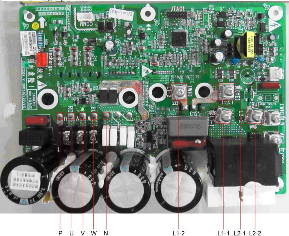
119 CH-IU48NK4 117


120 3 WIRING DIADRAM 3.1 Outdoor unit The actual wiring should always refer to the wiring diagram of the unit. Model: CH-IU09NK4, CH-IU12NK4 C&H NORDIC Commercial 4 Service Manual Model: CH-IU18NK4 118


121 Model: CH-IU24NK4, CH-IU30NK4 Model: CH-IU36NK4 119
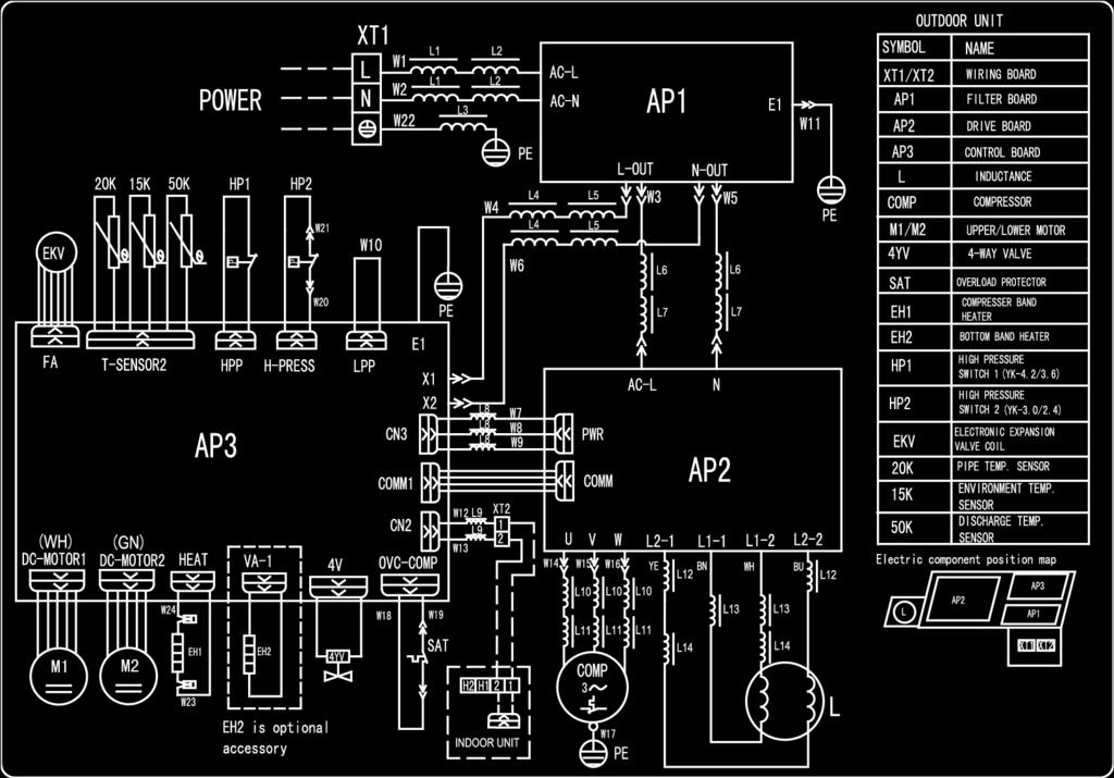
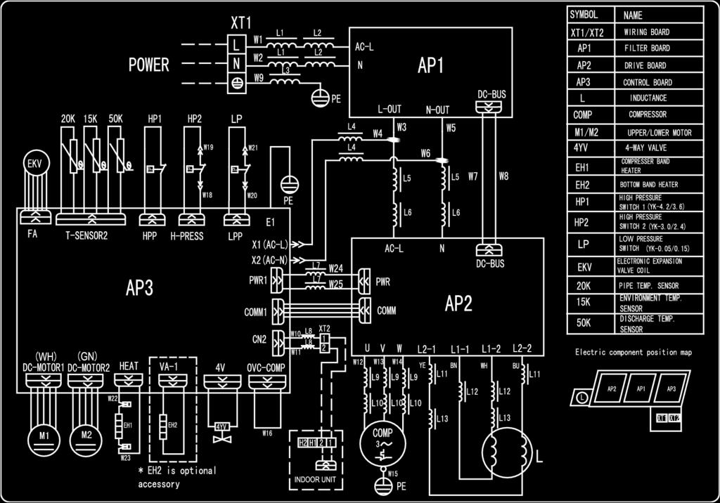
122 Model: CH-IU42NK4 Model: CH-IU48NK4 120

123 3.2 Indoor unit The actual wiring should always refer to the wiring diagram of the unit Duct Type Model: CH-ID09NK4, CH-ID12NK4, CH-ID18NK4, CH-ID24NK4, CH-ID30NK4, CH- ID36NK4, CH-ID42NK4 Model: CH-ID48NK4 121

124 3.2.2 Floor Ceiling Type C&H NORDIC Commercial 4 Service Manual Model: CH-IF09NK4, CH-IF12NK4, CH-IF18NK4, CH-IF24NK4, CH-IF30NK4, CH- IF36NK4, CH-IF42NK4, CH-IF48NK Cassette Type Model: CH-IC12NK4, CH-IC18NK4 122


125 Model: CH-IC24NK4, CH-IC30NK4 Model: CH-IC36NK4, CH-IC42NK4 123

126 Model: CH-IC48NK4 124


127 4 DISASSEMBLY AND ASSEMBLY PROCEDURE OF MAIN PARTS 4.1 Outdoor Unit 09/12K Disassembly and Assembly of external casing Remark : S t e p Illustration Handling Instruction 1. Remove external casing 1. Remove the top cover and handle; 2. Remove the grille, outer case and right side plate. 2. Remove motor 1. Remove the blade nut and then remove the blade; 2. Remove the motor from motor support. 3. Remove compressor 1. Discharge the refrigerant inside the pipeline and recycle the refrigerant during discharging; 2. Unsolder the 4-way valve assy from compressor; 3. Remove the nut fixing compressor; 4. Take away the compressor from chassis. 4. Assemble compressor 1. Fix the new compressor on to the chassis; 2. Connect the suction port and discharge port of compressor with the system pipes; 3. Properly connect the pwoer cord of compressor; 4. Renew the compressor electric heating belt and discharge temperature sensor; 5. Check if the compressor rotates in reverse and if the lubricant have leaked. 125


128 5. Assemble unit Assemble the unit in the reverse procedures of disassembly. 18K Disassembly and Assembly of external casing Remark : S t e p Illustration Handling Instruction 1. Remove external casing 1. Remove the top cover and handle; 2. Remove the grille, outer case and right side plate. 2. Remove motor 1. Remove the blade nut and then remove the blade; 2. Remove the motor from motor support. 3. Remove compressor 1. Discharge the refrigerant inside the pipeline and recycle the refrigerant during discharging; 2. Unsolder the 4-way valve assy from compressor; 3. Remove the nut fixing compressor; 4. Take away the compressor from chassis. 126


129 4. Assemble unit Assemble the unit in the reverse procedures of disassembly. 24/30k Disassembly and Assembly of external casing Remark : S t e p Illustration Handling Instruction 1. Remove external casing 1. Remove the top cover and handle; 2. Remove the grille, outer case, front side plate and right side plate. 2. Remove motor 1. Remove the blade nut and then remove the blade; 2. Remove the motor from motor support. 3. Remove compressor 1. Discharge the refrigerant inside the pipeline and recycle the refrigerant during discharging; 2. Unsolder the 4-way valve assy from compressor; 3. Remove the nut fixing compressor; 4. Take away the compressor from chassis. 127


130 4. Assemble unit Assemble the unit in the reverse procedures of disassembly. 36k Disassembly and Assembly of external casing Remark : S t e p Illustration Handling Instruction 1. Remove external casing 1. Remove the top cover and handle; 2. Remove the grille, outer case and right side plate. 2. Remove motor 1. Remove the blade nut and then remove the blade; 2. Remove the motor from motor support. 3. Remove gas liquid separator 1. Discharge the refrigerant inside the pipeline and recycle the refrigerant during discharging; 2. Unsolder the 4-way valve assy from gas liquid separator; 3. Remove the gas liquid separator. 128


131 4. Remove compressor 1. Discharge the refrigerant inside the pipeline and recycle the refrigerant during discharging; 2. Unsolder the 4-way valve assy from compressor; 3. Remove the nut fixing compressor; 4. Take away the compressor from chassis. 5. Assemble unit Assemble the unit in the reverse procedures of disassembly. 42k/48k/60k: Disassembly and Assembly of external casing Remark : S t e p Illustration Handling Instruction 1. Remove external casing 1. Remove the top cover and handle; 2. Remove the grille, outer case and right side plate. 2. Remove motor 1. Remove the blade nut and then remove the blade; 2. Remove the motor from motor support. 129


132 3. Remove gas liquid separator. 1. Discharge the refrigerant inside the pipeline and recycle the refrigerant during discharging; 2. Unsolder the 4-way valve assy from gas liquid separator; 3. Remove the gas liquid separator. 4. Remove compressor 1. Discharge the refrigerant inside the pipeline and recycle the refrigerant during discharging; 2. Unsolder the 4-way valve assy from compressor; 3. Remove the nut fixing compressor; 4. Take away the compressor from chassis. 5. Assemble unit Assemble the unit in the reverse procedures of disassembly. 130


133 4.2 Indoor Unit Duct type Removal and Assembly of Fan Motor Remarks: Before removing the fan, make sure to cut off the power firstly. S t e p Illustration Handling Instruction 1. Unplug the motor cables Cut off the power supply of indoor unit. Use screwdriver to remove the electric box cover and unplug the motor cables in electric box. 2. Remove the filter sub-assembly and air inlet cover board Remove the filter sub-assembly from the air inlet frame and use screwdriver to remove the air inlet cover board. 3. Remove the screws on fan sub-assembly. Remove the screws on fan sub-assembly. 4. Overturn the propeller housing Rotate the propeller housing to the air inlet according to arrow direction. 5. Loosen the fan and motor. Use inner hexagonal spanner to loosen the screws on fan and remove the clamp fixing the motor. 6. Replace the motor Firstly, disengage the motor from motor support. Then, sequentially disengage the fan sub-assembly form the motor shaft. Remove the motor from the air inlet and replace with new motor. In which, for the motor with automatic motor support, the motor support shall be removed in advance and then changed to the unit. 131


134 7. Assemble the unit in reverse to the disassembly procedures Assemble the unit in reverse to the disassembly procedures and energize it for testing. Disassembly of filter screen for return air. Remark: Make sure that the power supply is cut off before disassembling and protect all the parts during disassembly. Do not put filter screen near the high temperature heat source. S t e p Illustration Handling Instruction 1.Disassembly of filter screen for return air Compress the filter screen for return air down on the guide slot sponge, and remove according to the direction shown by the arrow. There are 2 filter screens for return air. Disassembly of electrical parts box cover panel and electrical parts box Remark: Make sure that the power supply is cut off before disassembling and protect all the parts during disassembly, especially the electrical components. Do not dampen or hit them S t e p Illustration Handling Instruction 1. Disassembly of electric box cover Disassemble the screw according to the position shown in the circle and the box and remove the electric box in the direction of the arrow. 2. Disassembly of electric parts box Disassemble the fastening screw and remove the electrical parts box. (As is shown in the graph, there are 2 fastening screws in the circle and the screws in the direction of arrow shall be disassembled too.) 132

 2. Disassembly of water-containing plate Disassemble the fastening screws on the water-containing plate, pull upward and remove the water-containing plate.")

135 Disassembly of water-containing plate Remark: Make sure that the power supply is cut off before disassembling and protect all the parts during disassembly. S t e p Illustration Handling Instruction 1. Disassembly of cover plate Disassemble the fastening screws on the cover plate and remove the cover plate. (As is shown in the graph, circle represents 6 fastening screws under the cover plate and the box represents two fastening screws on water-containing plate symmetrically arranged both on left and right.) 2. Disassembly of water-containing plate Disassemble the fastening screws on the water-containing plate, pull upward and remove the water-containing plate. Disassembled water-containing plate is shown in the graph. Disassembly of fan and motor Remark: Make sure that the power supply is cut off before disassembling and protect all the parts during disassembly. S t e p Illustration Handling Instruction Disassembly of fan motor Disassemble the fixing screws on the fan components. (As is shown in Graph 10, circle represents 6 screws.) Disassemble the fastening screws on the fan and motor. Remove the fan. (As is shown in Graph 11, box represents screws.) 133


136 Disassembly of evaporator Remark: Make sure that the power supply is cut off and protect the copper tube and aluminum fin. If the time for disassembly shall be long, put the copper tube under pressurized condition. S t e p Illustration Handling Instruction 1. Disassembly of fixing screws on the side panels of evaporator Disassemble the fastening screw connecting left and right side panels on the evaporator and the upper cover plate. (As is shown in the arrows direction in Graph.) 2. Disassemble fastening screws connecting evaporator valve seal-plate and joint flange Disassemble the fastening screws on the valve seal-plate and remove the valve seal-plate. Disassemble the fastening screws on the evaporators joint flange. (As is shown in the graph, box represents fastening screws on seal-plates while circle the fastening screws on joining flange. 3. Removal of evaporator Remove the evaporator. Removed evaporator is shown in the graph Cassette-type Unit Removal and Assembly of Fan Motor S t e p Illustration Handling Instruction 1. Loosen the screws fixing the water tray Use screwdriver to loosen the screws fixing the water tray 134


137 2. Remove the water tray Remove the water tray 3. Loosen the bolts fixing the fan Use spanner to loosen the bolts fixing the fan. 4. Remove the fan Remove the fan 5. Loosen the screws fixing the motor Use screwdriver to loosen the screws fixing the motor 6. Remove the motor and replace it Remove the motor and replace it 135


138 7. Tighten the screws fixing the motor Use screwdriver to tighten the screws fixing the motor. 8. Mount the fan and tighten the fixing bolts Mount the fan and use spanner to tighten the bolts fixing the fan. 9. Mount the water tray and tighten the screws Use screwdriver to loosen the screws fixing the water tray 136


 Disassembly of panel parts Remark: Make sure the power supply is cut off before disassembling and protect all the Step Illustration")

139 4.2.3 Floor Ceiling Type Model: CH-IF30NK4~CH-IF42NK4 Disassembly of panel grating module Remark: Make sure that the power supply is cut off before disassembling and protect all the parts during disassembly. Do not put filter screen near the high temperature heat source. Step Illustration Handling Instruction Disassembly of sub-assy of front grill Unscrew the 2 clasps of the upper grill and the 2 screws of the clasps. Open the grill, disassemble the 2 down clasps to remove the grill. Disassembly of right and left finishing plates Remark: Make sure the power supply is cut off before disassembling and protect all the parts during disassembly. Do not scratch the outer parts. Step Illustration Handling Instruction Disassembly of right and left finishing plates Disassemble the screws as shown in the graph with screwdriver and then push upward to remove the right and left finishing plates.(as is shown in the graph, arrow represents the position of screws.) Disassembly of panel parts Remark: Make sure the power supply is cut off before disassembling and protect all the parts during disassembly. Do not scratch the outer parts. Step Illustration Handling Instruction Disassembly of panel parts Unscrew the 3 sides screws on the cover to remove the cover. Disassembly of sub-assy of electric box Remark: Make sure that the power supply is cut off before disassembling and protect all the parts during disassembly, especially the components inside the box in case of water and hit. Step Illustration Handling Instruction Disassembly of electric box cover Disassemble 3 screws as shown by the arrow in the graph on left and remove the electric box cover. 137


140 Disassembly of air deflecting plate modules Remark: Make sure the power supply is cut off before disassembling and protect all the parts during disassembly, especially the joints of the air deflecting plate. S t e p Illustration Handling Instruction Disassembly of sub-assy of air deflecting plate Remove the air deflecting plates from the air deflecting plate support assembly, and then remove both ends from the air sweeping motor. joint (As is shown in the graph, arrow represents the support assembly and circle the air sweeping motor joint.) Disassemble of water-containing plate modules Remark: Make sure the power supply is cut off before disassembling and protect all the parts during disassembly. S t e p Illustration Handling Instruction Disassemble of water-containing plate modules Remove the water-containing plate modules. Disassembly of evaporator components Remark: Make sure that the power supply is cut off and protect the copper tube and aluminum fin. If the time for disassembly shall be long, seal the copper tube. S t e p Illustration Handling Instruction Disassembly of evaporator components Unscrew the 6 screws of evaporator, 3 screws of water groove press board and the 2 screws of water board to remove the evaporator. Disassembly of fixing plate sub-assy for air sweeping fans Remark: Make sure that the power supply is cut off before disassembling and protect all the parts during disassembly. S t e p Illustration Handling Instruction Disassembly of fixing plate sub-assy for air sweeping fans Remove the display board, mounting support and mounting plate of swing motor in turn. 138

 2.")

141 Disassembly of fan and motor components Remark: Make sure that the power supply is cut off before disassembling and protect all the parts during disassembly, especially the fastening screws for fans. S t e p Illustration Handling Instruction 1. Disassembly of front and back scroll cases Press the buckle at the joints of front and back scroll cases with hands and pull upward to remove the front scroll case. Then remove the screws on the back scroll case. Lift the buckle of back scroll case with hands and remove it. (As is shown in the graph, circle represents 2 screws on left and right.) 2. Disassembly of fans Unscrew the 2 screws of coupling, take out the rotating shaft and louver, then loosen the tighten screw of louver to remove the louver 3. Disassembly of bearing fixing plates Unscrew the 3 screws and 2 nuts of support to remove the mounting support. 4. Disassembly of motor Loosen the 2 screws of the motor attaching clamp, remove the motor attaching clamp and motor attaching clamp subassembly to remove the motor. Disassembly of right and left fixing plates Remark: Make sure that the power supply is cut off before disassembling and protect all the parts during disassembly. S t e p Illustration Handling Instruction Disassembly of right and left fixing plates Disassemble the bolts on right and left fixing plates with tools. (As is shown by the arrow in the graph.) 139


142 Model: CH-IF09NK4~CH-IF42NK4, CH-IF48NK4, CH-IF60NK4 Disassembly of panel grating module Remark: Make sure that the power supply is cut off before disassembling and protect all the parts during disassembly. Do not put filter screen near the high temperature heat source. Step Illustration Handling Instruction Disassembly of sub-assy of front grill Unscrew the 2 clasps of the upper grill and the 2 screws of the clasps. Open the grill, disassemble the 2 down clasps to remove the grill Disassembly of right and left finishing plates Remark: Make sure the power supply is cut off before disassembling and protect all the parts during disassembly. Do not scratch the outer parts. Step Illustration Handling Instruction Disassembly of right and left finishing plates Disassemble the screws as shown in the graph with screwdriver and then push upward to remove the right and left finishing plates.(as is shown in the graph, arrow represents the position of screws.) Disassembly of panel parts Remark: Make sure the power supply is cut off before disassembling and protect all the parts during disassembly. Do not scratch the outer parts. Step Illustration Handling Instruction Disassembly of panel parts Unscrew the 3 sides screws on the cover to remove the cover. Disassembly of sub-assy of electric box Remark: Make sure that the power supply is cut off before disassembling and protect all the parts during disassembly, especially the components inside the box in case of water and hit. Step Illustration Handling Instruction 1. Disassembly of electric box cover Disassemble 3 screws as shown by the arrow in the graph on left and remove the electric box cover. 140


 Disassemble of water-containing plate modules Remark: Make sure the power supply is cut off before disassembling and protect all the parts during disassembly.")


143 Disassembly of air deflecting plate modules Remark: Make sure the power supply is cut off before disassembling and protect all the parts during disassembly, especially the joints of the air deflecting plate. S t e p Illustration Handling Instruction Disassembly of sub-assy of air deflecting plate Remove the air deflecting plates from the air deflecting plate support assembly, and then remove both ends from the air sweeping motor. joint (As is shown in the graph, arrow represents the support assembly and circle the air sweeping motor joint.) Disassemble of water-containing plate modules Remark: Make sure the power supply is cut off before disassembling and protect all the parts during disassembly. S t e p Illustration Handling Instruction Disassemble of water-containing plate modules Remove the water-containing plate modules. Disassembly of evaporator components Remark: Make sure that the power supply is cut off and protect the copper tube and aluminum fin. If the time for disassembly shall be long, seal the copper tube. S t e p Illustration Handling Instruction Disassembly of evaporator components Unscrew the 6 screws of evaporator, 3 screws of water groove press board and the 2 screws of water board to remove the evaporator. Disassembly of fixing plate sub-assy for air sweeping fans Remark: Make sure that the power supply is cut off before disassembling and protect all the parts during disassembly. S t e p Illustration Handling Instruction Disassembly of fixing plate sub-assy for air sweeping fans Remove the display board, mounting support and mounting plate of swing motor in turn. 141


144 Disassembly of fan and motor components Remark: Make sure that the power supply is cut off before disassembling and protect all the parts during disassembly, especially the fastening screws for fans. S t e p Illustration Handling Instruction 1. Disassembly of front and back scroll cases Press the buckle at the joints of front and back scroll cases with hands and pull upward to remove the front scroll case. Then remove the screws on the back scroll case. Lift the buckle of back scroll case with hands and remove it. (As is shown in the graph, circle represents 2 screws on left and right.) Disassembly of fan and motor components Remark: Make sure that the power supply is cut off before disassembling and protect all the parts during disassembly, especially the fastening screws for fans. S t e p Illustration Handling Instruction 2. Disassembly of fans Unscrew the 2 screws of coupling, take out the rotating shaft and louver, then loosen the tighten screw of louver to remove the louver. 3. Disassembly of bearing fixing plates Unscrew the 3 screws and 2 nuts of support to remove the mounting support 4. Disassembly of motor Loosen the 2 screws of the motor attaching clamp, remove the motor attaching clamp and motor attaching clamp subassembly to remove the motor. Disassembly of right and left fixing plates Remark: Make sure that the power supply is cut off before disassembling and protect all the parts during disassembly. S t e p Illustration Handling Instruction Disassembly of right and left fixing plates Disassemble the bolts on right and left fixing plates with tools. (As is shown by the arrow in the graph.) 142
145 5 EXPLODED VIEWS AND SPARE PART LIST 5.1 Outdoor Unit Model: CH-IU09NK4/CH-IU12NK4 Exploded Views and spare parts list: 143
146 NO. Name of Part CH-IU09NK4 CH-IU12NK4 Part Code Quantity Part Code Quantity 1 Front Grill ' Front Panel P 1 ' P 1 3 Axial Flow Fan ' ' Brushless DC Motor ' Chassis Sub-assy P P 1 6 Drainage Connecter ' ' Compressor Gasket ' ' Compressor and Fittings ' Compressor Overload Protector(External) ' or or ' or or Strainer ' Strainer ' ' Electronic Expansion Valve ' ' Electric Expand Valve Fitting ' ' Valve ' ' Big Handle ' ' Right Side Plate Assy ' ' Valve Support ' ' Cut off Valve ' ' Temperature Sensor ' G 1 ' G 1 20 Silencer ' ' Magnet Coil ' ' Clapboard Sub-Assy ' ' Way Valve ' ' Pressure Protect Switch ' ' Terminal Board ' Terminal Board ' ' Condenser Assy ' ' Rear Grill ' ' Top Cover Plate ' ' Electric Box Assy ' Main Board ' Cover of Reactor Box ' ' Reactor ' ' Motor Support Sub-Assy ' '

147 Model: CH-IU18NK4 Exploded Views and spare parts list: 145
148 CH-IU18NK4 NO. Name of Part 146 Part Code Quantity 1 Front Grill ' Front Panel Axial Flow Fan ' Fan Motor Chassis Sub-assy P 1 6 Drainage Connecter ' Electrical Heater ' Motor Support Assy Compressor Overload Protector(External) ' Compressor Gasket ' Compressor and Fittings Strainer ' Strainer ' Pressure Protect Switch ' Cut off Valve Sub-Assy ' Cut off Valve ' Valve Support Assy ' P 1 18 Valve Cover Cut off Valve ' Handle ' Right Side Plate ' Strainer ' Silencer ' Way Valve ' Magnet Coil ' Temperature Sensor G 1 27 Electric Expand Valve Fitting Electronic Expansion Valve ' Clapboard Sub-Assy ' Supporter ' Rear Grill ' Terminal Board ' Terminal Board ' Condenser Assy ' Electric Box Cover Coping ' Electric Box Assy Main Board Main Board Left Handle ' Supporting Board(Condenser) ' Left Side Plate ' P 1

149 Model: CH-IU24NK4/ CH-IU30NK4 Exploded Views and spare parts list: 147
150 CH-IU24NK4 CH-IU30NK4 NO. Name of Part Part Code Quantity Part Code Quantity 1 Front Grill ' ' Cabinet ' P 1 ' P 1 3 Axial Flow Fan ' Front Side Plate ' P 1 ' P 1 5 Fan Motor ' ' Chassis Sub-Assy P 1 ' P 1 7 Drainage Connecter ' ' Electrical Heater(Compressor) ' ' Compressor Gasket ' ' Compressor and Fittings ' Bidirection Strainer ' ' Electric Expand Valve Fitting ' ' Pressure Protect Switch ' ' Silencer ' ' Pressure Protect Switch ' ' Valve Support Sub-Assy ' P 1 17 Right Side Plate Sub-Assy P 1 ' P 1 18 Valve Cover ' Valve ' ' Big Handle ' ' Cut off Valve ' ' Strainer ' ' Magnet Coil ' ' way Valve ' ' Strainer ' ' Temperature Sensor G 1 ' G 1 27 Electronic Expansion Valve ' ' Compressor Overload Protector(External) ' ' Compressor Overload Protector(External) ' Compressor Overload Protector(External) ' Clapboard ` Rear Grill ' ' Terminal Board ' ' Terminal Board ' ' Condenser Assy ' Electric Box Cover ' ' Top Cover Sub-Assy ' ' Electric Box Assy ' Main Board ' Main Board ' Condenser Support Plate ' ' Left Handle ' ' Electric Box Cover ' ' PFC Inductance ' ' Inductance Box Sub-Assy ' Motor Support Assy ' Left Side Plate ' P 1 ' P 1 148

151 Model: CH-IU36NK4 Exploded Views and spare parts list: 149
152 NO. Name of Part Part Code CH-IU36NK4 Quantity 1 Front Grill ' Handle ' Cabinet ' P 1 4 Front Side Plate Sub-Assy ' Chassis Sub-Assy ' P 1 6 Drainage Joint ' Electrical Heater(Compressor) ' Clapboard Sub-Assy ' Compressor Gasket ' Compressor ' Gas-liquid Separator Sub-Assy ' Compressor Overload Protector(External) or or Pressure Switch ' Muffler ' Filter ' Right Side Plate Sub-Assy ` P 1 17 Filter ' Valve Support Sub-Assy ' P 1 19 Cut-off Valve ' Cut-off Valve ' Electronic Expansion Valve Sub-Assy ` Temperature Sensor ' G 1 23 Filter ' Electronic Expansion Valve Coil ' Electronic Expansion Valve ` Pressure Switch ' Way Valve Assy ` way Valve ' Magnet Coil ' Rear Grill ' Condenser Assy ' Top Cover ' P 1 33 Condenser Support Plate ' Electric Box Assy ' Main Board ' PFC Inductance ' Main Board ' Filter Board ' Terminal Board ' Terminal Board ' Left Handle ' Motor Support Sub-Assy ` Left Side Plate ' P 1 44 Fan Motor ' Axial Flow Fan Blade '

153 Model: CH-IU42NM4 Exploded Views and spare parts list: 151
154 CH-IU42NM4 NO. Name of Part Part Code Quantity 1 Front Grill ' Diversion Circle ' Cabinet ' P 1 4 Handle ' Front Side Plate ' P 1 6 Axial Flow Fan ' Fan Motor ' Motor Support Sub-Assy ' Compressor Gasket ' Chassis Sub-assy ' P 1 11 electrical heater ' Valve Support Sub-Assy ' P 1 13 Compressor ' Cut off Valve ' Cut off Valve ' Filter ' Valve Cover ' Rear Side Plate ' P 1 19 Strainer ' Electronic Expansion Valve ' Electric Expand Valve Fitting ' Temperature Sensor ' G 1 23 Strainer ' Silencer ' Silencer ' Compressor Overload Protector(External) ' Compressor Overload Protector(External) ' Compressor Overload Protector(External) ' Compressor Overload Protector(External) ' Pressure Protect Switch ' Gas-liquid Separator Sub-Assy ' way Valve ' Magnet Coil ' Pressure Protect Switch ' Wire Clamp ' Clapboard ' Condenser Assy ' Rear Grill ' Coping ' P 1 36 Electric Box Assy Main Board ' Main Board ' Filter Board ' PFC Inductance ' Terminal Board ' Terminal Board ' Left Side Plate ' P 1 44 Fan Motor '

155 Model: CH-IU48NK4 Exploded Views and spare parts list: 153
156 CH-IU48NK4 NO. Name of Part Part Code Quantity 1 Front Grill ' Diversion Circle ' Cabinet ' P 1 4 Handle ' Front Side Plate ' P 1 6 Axial Flow Fan ' Fan Motor ' Motor Support Sub-Assy ' Chassis Sub-assy ' P 1 10 Compressor Gasket ' electrical heater ' Drainage Joint ' Electrical Heater ' Valve Support Sub-Assy ' P 1 15 Compressor ' Cut off Valve ' Cut off Valve ' Filter ' Strainer ' Valve Cover ' Rear Side Plate P 1 22 Electronic Expansion Valve ' Electric Expand Valve Fitting ' Strainer ' Temperature Sensor ' G 1 26 Silencer ' Pressure Protect Switch ' Pressure Protect Switch ' Gas-liquid Separator Sub-Assy ' way Valve ' Magnet Coil ' Pressure Protect Switch ' Wire Clamp ' Clapboard ' Condenser Assy ' Rear Grill ' Coping ' P 1 38 Electric Box Assy Main Board ' Filter Board ' Main Board ' Inductance ' Terminal Board ' Terminal Board ' Supporting Strip ' Left Side Plate ' P 1 47 Fan Motor '

157 5.2 Indoor Unit Duct Type Model: CH-ID09NK4 exploded view and spare parts list 155
158 CH-ID09NK4 NO. Name of Part Part Code Quantity 1 Top Cover Board Assy ' Electric Box Cover ' Left Side Plate Assy ' Electric Box Assy ' Main Board ' Terminal Board ' Terminal Board ' Left Evaporator Support ' Choke Plug of Drain Pipe ' Air intake side-board Sub-assy ' Water Tray Assy Evaporator Assy Lower Cover Plate Sub-Assy Right Support of Evaporator ' Supporter ' Brushless DC Motor ' Propeller Housing ' Right Side Plate Assy ' Hook ' Centrifugal fan ' Front Volute Casing ' side plate sub- assy of return air frame ' Filter ' Temperature Sensor ' G 1 25 Ambient Temperature Sensor ' Display Board '

159 Model: CH-ID12NK4/CH-ID18NK4 exploded view and spare parts list 157
160 CH-ID12NK4 CH-ID18NK4 NO. Name of Part Part Code Quantity Part Code Quantity 1 Bottom Cover Plate ' ' Cover Of Air-In ' ' Propeller Housing ' ' Centrifugal fan ' ' Left Side Plate Sub-Assy ' Electric Box Assy ' ' Terminal Board ' ' Electric Box Cover ' Terminal Board ' Main Board ' Seal Of Connection Pipe Seal Of Connection Pipe Water Tray Assy ' ' Strainer ' ' left Supporting Board subassy of evaporator ' ' Filter ' ' Evaporator Assy ' ' Evaporator Assy ' ' side plate sub- assy of return air frame ' ' Top Cover Board Sub-assy ` ` Display Board ' Ambient Temperature Sensor ' ' Temperature Sensor ' G 1 ' G 1 24 Hook ' ' Right Side Plate Sub-Assy ' ' Choke Plug of Water Pipe ' ' Right Support of Evaporator ' ' Centrifugal fan assy ` ' Front Volute Casing ' ' Return air frame sub-assy ' ' DC Brushless Motor ' ' Motor Support Sub-Assy ' '

161 Model: CH-ID24NK4/CH-ID30NK4 exploded view and spare parts list 159
162 NO. Name of Part CH-ID24NK4 CH-ID30NK4 Part Code Quantity Part Code Quantity 1 Blower ' ' Blower Mounting Plate Sub-Assy ` ' Supporter ' ' Supporter ` ' Brushless DC Motor ' ' Blower ' ' Lower Cover Plate Sub-Assy ' ' Drain Pan Assy ' ' Left Side Plate Assy ' ' Choke Plug of Drain Pipe ' ' Evaporator Assy ' ' Filter Sub-Assy ' ' Guiding Slot of Filter ' ' Hook ' ' Top Cover Board Assy ' ' Temperature Sensor ` ' Ambient Temperature Sensor ' ' Display Board ' ' Main Board ' ' Electric Box Assy ' ' Terminal Board ' ' Terminal Board ` ` Electric Box Cover ' ' Cover Plate Sub-Assy ' ' Right Side Plate Sub-Assy ' '

163 Model: CH-ID36NK4/CH-ID42NK4 exploded view and spare parts list 161
164 CH-ID36NK4 CH-ID42NK4 NO. Name of Part Part Code Quantity Part Code Quantity 1 Main Board ' ' Terminal Board ' ' Terminal Board ' ' Hook ' ' Top Cover Board Assy ' ' Electric Box Assy ' ' Right Side Plate Sub-Assy ' ' Volute Casing (Upper) ' ' Blower Mounting Plate Sub-Assy ' ' Brushless DC Motor ' ' Centrifugal Fan Blade ' ' Volute Casing (Lower) ' ' Lower Cover Plate Sub-Assy ' ' Drain Pan Assy ' ' Drain Pipe Plug ' ' Left Side Plate Assy ' ' Support Plate of Evaporator ' ' Evaporator Assy ' ' Filter Sub-Assy ' ' Side Plate of Air Inlet ' ' Temperature Sensor ' G 1 ' G 1 22 Ambient Temperature Sensor ' ' Display Board ' '

165 Model: CH-ID48NK4 exploded view and spare parts list 163
166 CH-ID36NK4 NO. Name of Part Part Code Quantity 1 Display Board ' Temperature Sensor ` Tube Sensor ` Left Side Plate Sub-Assy ' Propeller Housing(Upper) ' Front Side Plate ' Centrifugal Fan ' Brushless DC Motor ' Blower Mounting Plate Sub-Assy ' Propeller Housing(Lower) ' Bottom Cover Board Assy ' Drain Pan Assy ' Pump Drainpipe Water Level Switch Water Pump Assy Choke Plug of Drain Pipe ' Hook ' Right Side Plate Sub-Assy ' Evaporator Assy ' Filter Sub-Assy ' Electric Box Assy ' Cold Plasma Device Sub-Assy Terminal Board ' Terminal Board ' Main Board ' Main Board ' Top Cover Plate Assy '

167 5.2.2 Cassette Type Model: CH-IC12NK4/CH-IC18NK4 exploded view and spare parts list. 165
168 NO. Name of Part CH-IC18NK4 CH-IC12NK4 Part Code Quantity Part Code Quantity 1 Rear Grill ' ' Brushless DC Motor ' ' Water Tray Assy ' ' Water Pump ' ' Supporter ' ' Water Level Switch ` ` Pump Drainpipe ' ' Water Pump Assy ' ' Right Side Plate Sub-Assy ' Bottom Foam Assy ' ' Base Plate Assy ' ' Body Installing Support ' ' Left Side Plate Sub-Assy ' ' Pressure Plate of Outlet Pipe ' ' Electric Box Assy ' ' Terminal Board ' ' Terminal Board ' ' Main Board ' ' Transformer ' ' Front Side Plate Sub-Assy ' ' Drain Hose Sub-Assy ' ' Room Sensor ' ' Tube sensor ' ' Remote Controller ' W 1 ' W 1 25 Evaporator Assy ' ' Supporter ' ' Centrifugal Fan ' '
169 Model: CH-IC24NK4/CH-IC30NK4/CH-IC36NK4/CH-IC42NK4 exploded view and spare parts list. 167
170 NO. Name of Part CH-IC24NK4 CH-IC30NK4 Part Code Quantity Part Code Quantity 1 Electric Box Cover Sub-Assy1 ' ' Electric Box Assy ' ' Terminal Board ' ' Terminal Board ' ' Electric Base Plate ' ' Water Tray Assy ' ' Fan Fixer ' ' Centrifugal Fan ' ' Evaporator Assy ' ' Left Side Plate Assy ' ' Front Side Plate assy ' ' Base Plate Assy ' ' Connected Board Assy of Evaporator ' ' Tube Exit Plate Assy ' ' Bottom Foam Assy ' ' Pump Support ' ' Pump Drainpipe ' ' Pump Cover Board Assy ' ' Water Pump ' ' Water Level Switch ' ' Evaporator Support Assy ' ' Right Side Plate Assy ' ' Body Installing Plate ' ' Rear Side Plate Assy ' ' Brushless DC Motor ' ' Drain Hose Sub-Assy ' ' Room Sensor ' ' Temperature Sensor ' G 1 ' G 1 29 Remote Controller ' W 1 ' W 1 30 Diversion Circle ' ' Main Board ' ' Electric Box Cover Sub-Assy2 ' '
171 NO. Name of Part CH-IC36NK4 CH-IC42NK4 Part Code Quantity Part Code Quantity 1 Electric Box Cover Sub-Assy1 ' ' Electric Box Assy ' ' Terminal Board ' ' Terminal Board ' ' Electric Base Plate ' ' Water Tray Assy ' ' Fan Fixer ' ' Centrifugal Fan ' ' Evaporator Assy ' ' Left Side Plate Assy ' ' Front Side Plate assy ' ' Base Plate Assy ' ' Connected Board Assy of Evaporator ' ' Tube Exit Plate Assy ' ' Bottom Foam Assy ' ' Pump Support ' ' Pump Drainpipe ' ' Pump Cover Board Assy ' ' Water Pump ' ' Water Level Switch ' ' Evaporator Support Assy ' ' Right Side Plate Assy ' ' Body Installing Plate ' ' Rear Side Plate Assy ' ' Brushless DC Motor ' ' Drain Hose Sub-Assy ' ' Room Sensor ' ' Temperature Sensor ' G 1 ' G 1 29 Remote Controller ' W 1 ' W 1 30 Diversion Circle ' ' Main Board ' ' Electric Box Cover Sub-Assy2 ' '

172 Model: CH-IC48NK4/CH-IC60NK4 exploded view and spare parts list. 170
173 CH-IC48NK4 NO. Name of Part Part Code Quantity 1 Electric Box Cover Plate ' P 1 2 Electric Box Assy ' Terminal Board ' Terminal Board ' Main Board ' Drain Pan Assy ' Centrifugal Fan ' Evaporator Assy ' Filter ' Foam Assy ' Connection Sheet Sub-Assy ' Left and Right Side Board ' Seat Board Sub-Assy ' Tube Exit Plate Sub-Assy ' Mounting Board ' Front Side Plate ' Drain Hose ' Water Pump Assy ' Pump Cover Board Assy ' Liquid Level Switch Sub-Assy ' Brushless DC Motor ' Rear Side Plate ' Fan Fixer ' Drain Hose Sub-Assy ' Room Sensor ' Temperature Sensor ' G 1 27 Remote Controller ' W 1 28 Diversion Circle '

174 5.2.3 Floor Ceiling Type C&H NORDIC Commercial 4 Service Manual Model: CH-IF09NK4/CH-IF12NK4/CH-IF18NK4/CH-IF24NK4 exploded view and spare parts list. 172
175 CH-IF09NK4 CH-IF12NK4 NO. Name of Part Part Code Quantity Part Code Quantity 1 Tube Sensor ' ' Room Sensor ' ' Connection Board ' ' Right Cover Plate ' ' Plate Board of Water Releasing Flume ' ' Installation Supporting Frame ' ' Axile Bush ' ' Right Side Plate Sub-Assy ' ' Water Releasing Flume ` ` Connected Board (Evaporator) ` ' Air Louver ' ' Guide Louver Support ' ' Rotating Shaft ' ' Front Connection Board ' P 1 ' P 1 15 Guide Louver ' ' Supporter ' ' Fixed Mount ' R 1 ' R 1 18 Display Board ' ' Evaporator Assy ' ' Rear Side Plate Assy ' ' Rotating Shaft ' ' Connecting Rod ' ' Rotating Shaft ' ' Stepping Motor ' ' Installation Supporting Frame ' ' Left Side Plate Sub-Assy ' ' Electric Box Assy ' ' Main Board ' ' Electric Box Cover ' ' Left Cover Plate ' ' Terminal Board ' ' Terminal Board ' ' Mid-clapboard Sub-Assy ' ' Support of Motor Bearing ' ' O-Gasket of Bearing ' ' Rotary Axis Sub-Assy ' ' Centrifugal Fan ' ' Joint Slack ' ' Support ' ' Clamping Band Assy ' ' DC brushless Motor ' ' Support ' ' Rear Connection Board ' ' Front Volute Casing ' ' Rear Volute Casing ' ' Drain Pan Assy ' ' Top Cover Board Sub-Assy ' ' Front Grill Sub-Assy ' ' Drain Pipe Sub-Assy ' '
176 CH-IF18NK4 CH-IF24NK4 NO. Name of Part Part Code Quantity Part Code Quantity 1 Tube Sensor ' ' Room Sensor ' ' Connection Board ' ' Right Cover Plate ' ' Plate Board of Water Releasing Flume ' ' Installation Supporting Frame ' ' Axile Bush ' ' Right Side Plate Sub-Assy ' ' Water Releasing Flume ` ` Connected Board (Evaporator) ' ' Air Louver ' ' Guide Louver Support ' ' Rotating Shaft ' ' Front Connection Board ' P 1 ' P 1 15 Guide Louver ' ' Supporter ' ' Fixed Mount ' R 1 ' R 1 18 Display Board ' ' Evaporator Assy ' ` Rear Side Plate Assy ' ' Rotating Shaft ' ' Connecting Rod ' ' Rotating Shaft ' ' Stepping Motor ' ' Installation Supporting Frame ' ' Left Side Plate Sub-Assy ' ' Electric Box Assy ' ' Main Board ' ' Electric Box Cover ' ' Left Cover Plate ' ' Terminal Board ' ' Terminal Board ' ' Mid-clapboard Sub-Assy ' ' Support of Motor Bearing ' ' O-Gasket of Bearing ' ' Rotary Axis Sub-Assy ' ' Centrifugal Fan ' ' Joint Slack ' ' Support ' ' Clamping Band Assy ' ' DC brushless Motor ' ' Support ' ' Rear Connection Board ' ' Front Volute Casing ' ' Rear Volute Casing ' ' Drain Pan Assy ' ' Top Cover Board Sub-Assy ' ' Front Grill Sub-Assy ' ' Drain Pipe Sub-Assy ' '

177 Model: CH-IF30NK4/CH-IF36NK4/CH-IF42NK4 exploded view and spare parts list. 175
U-MATCH SERIES DC INVERTER AIR CONDITIONERS SERVICE MANUAL
 U-MATCH SERIES DC INVERTER AIR CONDITIONERS SERVICE MANUAL T1/R410A/50Hz (GC201304 - ) CONTENTS PRODUCT... 2 1 MODELS LIST... 2 1.1 Outdoor Unit...2 1.2 Indoor Unit...3 2 NOMENCLATURE... 4 2.1 Outdoor
Wired Controller XK60
 Owner's Manual Commercial Air Conditioners Thank you for choosing Commercial Air Conditioners, please read this owner s manual carefully before operation and retain it for future reference. User Notice
Wired Remote Controller XK19 and Wireless Remote Controller YT1F
 and Wireless Remote Controller YT1F Owner's Manual Commercial Air Conditioners Thank you for choosing Commercial Air Conditioners, please read this owner s manual carefully before operation and retain
SERVICE MANUAL UNI SPLIT SERIES. ASC-xxBI, ASD-xxBI, ASF-xxBI, ASGE-xxBI, ASGE-xxBI-3
 EN SERVICE MANUAL UNI SPLIT SERIES ASC-xxBI, ASD-xxBI, ASF-xxBI, ASGE-xxBI, ASGE-xxBI-3 Original instructions IMPORTANT NOTE: Read this manual carefully before installing or operating your new air conditioning
OWNER S MANUAL DUCTED INVERTER. (English) (SDHV SERIES)
 (SDHV SERIES)") OWNER S MANUAL DUCTED INVERTER (English) (SDHV SERIES) IMPORTANT As with any product that has moving parts or is subject to wear and tear, it is VERY IMPORTANT that you maintain your air conditioner and
OWNER S MANUAL DUCTED INVERTER (English) (SDHV SERIES) IMPORTANT As with any product that has moving parts or is subject to wear and tear, it is VERY IMPORTANT that you maintain your air conditioner and
CASSETTE, FLOOR&CEILING, DUCT UNITS OUTDOOR UNITS
 SERVICE MANUAL MULTI COMBI OUTDOOR AND INDOOR UNITS CASSETTE, FLOOR&CEILING, DUCT UNITS OUTDOOR UNITS (36k,42k) COMBINATION TABLE (unit: kw) MC-E18AI MC-E24AI MC-E28AI MC-E36AI 1 model 2 models 2 models
Buttons on remote controller
 Buttons on remote controller 1 2 3 4 5 2 1 6 7 3 8 5 6 4 7 10 8 10 15 15 ON/OFF button button MODE button SWING button FAN button Introduction for icons on display screen button TIMER OFF button CLOCK
FAN COILS wall mounted
 SERVICE MANUAL FAN COILS wall mounted SF-51H, SF-68H, SF-85H PRODUCT MODELS LIST Model Name Cooling Capacity (W) Product Code Air Flow (m 3 /h) Power Supply (V,Ph,Hz) Remarks SF-51H 2700 EM55001260 550
Wired Controller XK46
 Owner's Manual Air Conditioners Thank you for choosing Commercial Air Conditioners,please read this owner s manual carefully before operation and retain it for future reference. User Notices The power
OWNER S MANUAL DLFCAB / DLFCHB / DLFDAB / DLFDHB High Wall Ductless System Sizes 09 36
 OWNER S MANUAL DLFCAB / DLFCHB / DLFDAB / DLFDHB High Wall Ductless System Sizes 09 36 TABLE OF CONTENTS PAGE SAFETY PRECAUTIONS... 2 GENERAL... 2 INDOOR UNIT PART NAMES... 3 REMOTE CONTROL PART NAMES...
Operating Functions Temperature Parameters
 Operating Functions Temperature Parameters Room set temperature (T set) Room ambient temperature (T amb) Fundamental Functions After powered on, no matter when the compressor is started, the time interval
Owner's Manual. Owner's Manual. Air Conditioners
 Wired Controller XK76 Owner's Manual Owner's Manual Air Conditioners Thank you for choosing Air Conditioners, please read this owner s manual carefully before operation and retain it for future reference.if
Operation Manual of The Ducted Split Type Air-Conditioning Units
 Installation and Operation Manual Operation Manual of The Ducted Split Type Air-Conditioning Units Applicable Models : FG(R)20/BNa-M FG(R)25/BNa-M FG(R)30/BNa-M FG(R)40/BNa-M MUCH-20-H4 MUCH-25-H4 MUCH-30-H4
Service Manual. Multi-Pipe VRF Outdoor Units VOM0355H2RE508 VOM0362H2RE Innovair Corporation. All Rights Reserved.
 Service Manual Multi-Pipe VRF Outdoor Units VOM0355H2RE508 VOM0362H2RE509 2015 Innovair Corporation. All Rights Reserved. www.innovair.com/support Contents PRODUCT... 1 1 MODELS LIST... 2 1.1 Outdoor Unit...
CENTRAL AIR CONDITIONERS SUPER FREE MATCH SERIES SERVICE MANUAL. T1/R410A/50Hz ( GC )
") CENTRAL AIR CONDITIONERS SUPER FREE MATCH SERIES SERVICE MANUAL T1/R410A/50Hz ( GC201405 - ) Contents Contents... 2 PRODUCT... 2 1 MODELS LIST... 2 1.1 Outdoor Unit... 2 1.2 BU Module... 2 1.3 Indoor Unit...
CENTRAL AIR CONDITIONERS SUPER FREE MATCH SERIES SERVICE MANUAL T1/R410A/50Hz ( GC201405 - ) Contents Contents... 2 PRODUCT... 2 1 MODELS LIST... 2 1.1 Outdoor Unit... 2 1.2 BU Module... 2 1.3 Indoor Unit...
Operating and Installation Instructions Manual
 Operating and Installation Instructions Manual MODEL: Indoor Unit FSPI-091B FSPI-121B FSPI-181B FSPI-241B FSPI-301B FSPI-361B FSPI-451B FSPI-501B FSPI-361B FSPI-451B FSPI-501B FSPI-601B Outdoor Unit FSOI-091B
OWNER S MANUAL. R 410A Ductless Split System Air Conditioner and Heat Pump
 R 410A Ductless Split System Air Conditioner and Heat Pump Models DLC4(A/H) Outdoor Unit, DLF4(A/H) Indoor Unit Sizes 9K, 12K, 18K, 24K, 30K and 36K Please read the operating instructions and safety precautions
High Wall Split Systems Cool Only 9K - 12K - 18K - 24K. Auto. Auto. Fan Speed. Smart LCD Wireless Control. Auto Mode.
 HFC4 1 0 A 0-40V ~, 0Hz 1Ph High Wall Split Systems Cool Only 9K - 1K - 18K - 4K R-410A IAQ $ Auto Auto Fan Speed Timer s Easy Flexible Installation Smart LCD Wireless Control Auto Mode Auto Restart Easy
DC inverter Outdoor-air Processing unit (GC )
") DC inverter Outdoor-air Processing unit (GC201109- ) ER CONDITIONERS GREE MAKING BETTER CONDITIONERS GREE MAKING BETTER CONDITIONERS GREE MAKING BETTERNDITINER TECHNICAL SALES GUIDE-50Hz CAPACITY RANGE:14~56kW
DC inverter Outdoor-air Processing unit (GC201109- ) ER CONDITIONERS GREE MAKING BETTER CONDITIONERS GREE MAKING BETTER CONDITIONERS GREE MAKING BETTERNDITINER TECHNICAL SALES GUIDE-50Hz CAPACITY RANGE:14~56kW
V ~, 50Hz 1Ph. High Wall Split Systems Heat Pump 9K - 12K - 18K - 24K - 28K. Auto. Auto Fan Speed. Auto. Smart LCD Wireless Control.
 HFC4 1 0 A 0-40V ~, 0Hz 1Ph High Wall Split Systems Heat Pump 9K - 1K - 18K - 4K - 8K R-410A Compressor Super Quiet AMS Anti-dust Filters Auto Fan Speed Timer Functions Defrost Protection Smart LCD Wireless
Split Air Conditioner
 O W N E R ' S M A N U A L C&H A IR C O N D ITI O N E R S Split Air Conditioner DELUXE SERIES MODELS: CH-S07LHA CH-S09LHA CH-S12LHA СH-S18LHA CH-S24LHA Thank you for selecting С&H air conditioners. Please
Hi - Wall Split Systems 12K - 18K - 24K
 R22 220-240V ~ 50Hz 1Ph Hi - Wall Split Systems 12K - 18K - 24K Technology Tropical Compressor Super Quiet Auto Auto Fan Speed Auto Restart Function Self diagnostic function Active Carbon Electrostatic
Split Air Conditioner
 O W N E R ' S M A N U A L M A N U A L C&H A IR C O N D ITI O N E R S Split Air Conditioner SMART SERIES MODELS: CH-S07LH/R CH-S09LH/R CH-S12LH/R СH-S18LH/R CH-S24LH/R Thank you for selecting С&H air conditioners.
PORTABLE AIR CONDITIONER
 OWNER S MANUAL PORTABLE AIR CONDITIONER Model: CH-M09K6S F or proper operation, please read and keep this manual carefully. Designed by Cooper&Hunter International Corporation, Oregon, USA www.cooperandhunter.com
SALVADOR ESCODA S.A. OWNER S MANUAL. Provenza, planta Barcelona Tel Fax
 SALVADOR ESCODA S.A. OWNER S MANUAL Provenza, 392 2 planta 08025 Barcelona Tel. +34 93 446 27 81 Fax +34 93 446 27 96 export@salvadorescoda.com CONTENTS Operation and maintenance Notice for operation 1
Hi - Wall Split Systems. Super Quiet. Auto. Mode. Wireless Control. Smart Airflow ECO ECO. Function SLEEP. Vertical Auto Swing.
 R407C 220-240V ~, 50Hz Hi - Wall Split Systems Technology Tropical Compressor Super Quiet Auto Mode Auto Restart Easy Flexible Installation IAQ Anti-dust Filters AMS AMS Wireless Control Independent Dehumidification
Change for Life. Service Manual
 Change for Life Service Manual Models: GWH09QB-K3DNA1G GWH09QB-K3DNA2G GWH09QB-K3DNA5G GWH09QB-K3DNB2G GWH09QB-K3DNB4G GWH09QB-K3DNB6G GWH12QC-K3DNA1G GWH12QC-K3DNA2G GWH12QC-K3DNA5G GWH12QC-K3DNB2G GWH12QC-K3DNB4G
USER S MANUAL. Remote Controller 88-MACC007-1A-EN
 USER S MANUAL Remote Controller 1 This is a general use remote controller that can be used with multiple models/units. Some functions will not apply to all models. Functions that are not operational will
1 Summary and features. Service Manual. Model QSVMI-09A QSVMI-12A QSVMI-18A
 Summary and features Service Manual Model QSVMI-09A QSVMI-2A QSVMI-8A 2 Technical specifications Model QSVMI-09A QSVMI-2A QSVMI-8A Fan Motor Speed (r/min) (SH/H/M/L) 50/050/900/750 50/050/900/750 250/050/950/800
2 NOMENCLATURE 3 FUNCTION 4 PRODUCT DATA
 CONTENTS PRODUCT... 2 1 MODELS LIST... 2 1.1 Outdoor Unit... 2 1.2 Indoor Unit... 3 2 NOMENCLATURE... 4 3 FUNCTION... 4 4 PRODUCT DATA... 5 4.1 Product Data at Rated Condition... 6 4.2 Operation Range...
1. MODELS LIST NOMENCLATURE FEATURES PRODUCT DATA FAN CHARACTERISTICS CLEARANCE DATA...
 FIXED FREQUENCY U-MATCH AIR CONDITIONERS TECHNICAL SALES GUIDE Capcity Range: 18000~ 60000 Bth h T3R2250Hz CONTENTS 1. MODELS LIST... 3 2. NOMENCLATURE... 4 3. FEATURES... 5 4. PRODUCT DATA... 9 5. FAN
Submittal Data: LIVS09HP230V1B. Job Name Location Date. Submitted To. Cool Quiet Comfort & more 9,000 BTU/H (208/230V) Wall Mounted Heat Pump System
 Wall Mounted Heat Pump System") Submittal Data: Cool Quiet Comfort & more 9,000 BTU/H (208/230V) Wall Mounted Heat Pump System Job Name Location Date Purchaser Engineer Submitted To For Unit Designation Schedule No. GENERAL FEATURES
Submittal Data: Cool Quiet Comfort & more 9,000 BTU/H (208/230V) Wall Mounted Heat Pump System Job Name Location Date Purchaser Engineer Submitted To For Unit Designation Schedule No. GENERAL FEATURES
RG57F3(B)/BGEFU1 Wireless Remote Controller. Service Manual
/BGEFU1 Wireless Remote Controller. Service Manual") RG57F3(B)/BGEFU1 Wireless Remote Controller Service Manual TABLE OF CONTENTS PAGE INTRODUCTION... 1 HANDLING THE REMOTE CONTROLLER... 2 STANDARD FUNCTION BUTTONS... 3 ACCESSING THE SERVICE FUNCTIONS...
RG57F3(B)/BGEFU1 Wireless Remote Controller Service Manual TABLE OF CONTENTS PAGE INTRODUCTION... 1 HANDLING THE REMOTE CONTROLLER... 2 STANDARD FUNCTION BUTTONS... 3 ACCESSING THE SERVICE FUNCTIONS...
OWNER S MANUAL HIGH WALL INVERTER. (English) (BSHVD1S SERIES)
 (BSHVD1S SERIES)") OWNER S MANUAL HIGH WALL INVERTER (English) (BSHVD1S SERIES) IMPORTANT As with any product that has moving parts or is subject to wear and tear, it is VERY IMPORTANT that you maintain your air conditioner
OWNER S MANUAL HIGH WALL INVERTER (English) (BSHVD1S SERIES) IMPORTANT As with any product that has moving parts or is subject to wear and tear, it is VERY IMPORTANT that you maintain your air conditioner
Submittal Data: VIR12HP230V1B. Job Name Location Date. Submitted To
 Submittal Data: Innovative Ductless solutions 12,000 BTU/H (208/230V) Wall Mounted Heat Pump System Job Name Location Date Purchaser Engineer Submitted To For Unit Designation Schedule No. GENERAL FEATURES
USER'S MANUAL MULTI COMBI SERIES FLOOR&CEILING MC-F09,12,18,24AI
 USER'S MANUAL MULTI COMBI SERIES FLOOR&CEILING MC-F09,12,18,24AI User Notice When operating, the entire capacity of the cooperating indoor unit should be not larger than 150% of outdoor unit. Otherwise,
Submittal Data: VIR09HP115V1B Job Name Location Date. Submitted To. Innovative Ductless solutions 9,000 BTU/H (115V) Wall Mounted Heat Pump System
 Wall Mounted Heat Pump System") Submittal Data: Job Name Location Date Purchaser Engineer Submitted To For Unit Designation Schedule No. GENERAL FEATURES -Compact and Quiet Design -High Efficiency DC Inverter Technology -Wireless Remote
Submittal Data: Job Name Location Date Purchaser Engineer Submitted To For Unit Designation Schedule No. GENERAL FEATURES -Compact and Quiet Design -High Efficiency DC Inverter Technology -Wireless Remote
All DC Inverter Multi VRF
 All DC Inverter Multi VRF In 2012, Gree highly promoted GMV5 All DC Inverter Multi VRF New breakthrough in comfort ability, intelligent control and design. Eight prominent advantages More powerful product
OWNER S MANUAL. High-Wall Fan Coil Unit CONTENTS
 OWNER S MANUAL High-Wall Fan Coil Unit Page GENERAL 2,3 OPERATING MODES 2 REMOTE CONTROL 2 OPERATION 3-9 REMOTE CONTROL OPERATION 3 INDOOR UNIT DISPLAY 5 EMERGENCY OPERATION 5 PRESSING THE ON/OFF BUTTON
Submittal Data: VIR24HP230V1B. Job Name Location Date. Submitted To
 Submittal Data: Innovative Ductless solutions 24,000 BTU/H (208/230V) Wall Mounted Heat Pump System Job Name Location Date Purchaser Engineer Submitted To For Unit Designation Schedule No. GENERAL FEATURES
Ducted inverter reverse cycle air conditioning
 Ducted inverter reverse cycle air conditioning What is ducted inverter reverse cycle air conditioning? Ducted inverter reverse cycle air conditioning is an ideal solution for whole-of-home or office cooling
Submittal Data: UMAT48HP230V1AF. Job Name Location Date. Submitted To
 Innovative Ductless Mini Split Solution Job Name Location Date Purchaser Engineer Submitted To For Unit Designation Schedule No. GENERAL FEATURES -Multi-Speed Fan -4-way Discharge Air -Swing Louvers -Wireless
PDA20DX Air Purifying Dehumdifier Manual
 PDA20DX Air Purifying Dehumdifier Manual Index Important Safe Guards Ambient Environment For Operating Components Diagrams---Parts Names Operating Introduction---How to operate - Functions of Control Panel
Service Manual A16EW4H4R09 A16EW4H4R12 A16EW4H4R18
 Service Manual A16EW4H4R09 A16EW4H4R12 A16EW4H4R18 ON/ OFF MODE FAN CLOCK TIMER ON X-FAN TEMP TIMER OFF TURBO SLEEP LIGHT A16EW4H4R09 A16EW4H4R12 A16EW4H4R18 1 2 A16EW4H4R09 A16EW4H4R12 A16EW4H4R18 3
WORKING PROGRAM. Heating dehumidifying cooling T 27
 I. Functions and Operation Modes WORKING PROGRAM The operation modes of the unit run like the following: Auto cooling dehumidifying heating --------------------------------------- Note: Cooling only unit
BTU Units WORKING PROGRAM MANUAL
 9000-24000BTU Units WORKING PROGRAM MANUAL SUMMARIZE FUNCTIONS & OPERATION MODES TIMER, SLEEP MODE, FAN SPEED PROTECTION FUNCTIONS EMERGENCY SWITCH TEST GUIDE MEMORY FUNCTIONS SUMMARIZE The Operation Modes
0RGHOV,QGRRU 8QLW MWM36Y3J 2XWGRRU 8QLW MRM36Y3J 11
 MWM36Y3J MRM36Y3J 11 Content Operation Notices Precautions...1 Parts name...2 Screen Operation Guide Buttons on remote controller...3 Introduction for icons on display screen...3 Introduction for buttons
Owner's Manual TABLE OF CONTENTS
 40MAQ High Wall Ductless System Sizes 09 to 36 Owner's Manual TABLE OF CONTENTS PAGE A NOTE ABOUT SAFETY... 2 GENERAL... 2 PART NAMES... 3 FUNCTION BUTTONS... 4 DISPLAY PANELS... 5 REMOTE CONTROL... 6
SERVICE MANUAL MUY-GL24NA - U1. No. OBH733. Models HFC. Revision B: REVISED EDITION-B R410A
 Revision B: MUZ-GL09NA- U8 and MUZ-GL09NAH- U8 have been added. Please void OBH733 REVISED EDITION-A. OUTDOOR INDOOR UNIT UNIT SERVICE MANUAL HFC utilized R410A. OBH733 REVISED EDITION-B Models MUZ-GL09NA
Innovative Ductless Mini Split Solution Submittal Data: GUHD24ND3FO/GKH24D3FI Job Name Location Date
 Innovative Ductless Mini Split Solution Submittal Data: GUHD24ND3FO/GKH24D3FI 24,000 BTUH 24,000 Ceiling BTU/H Cassette Ceiling Heat Casse3e Pump Heat System Pump System Job Name Location Date Purchaser
15A Operating Range Communication Wire Size 18-2 AWG / 300V THHN Cooling (Max) 118 F (48 C)
 118 F (48 C)") Innovative Ductless Mini Split Solution Job Name Location Date Purchaser Engineer Submitted To For Unit Designation Schedule No. GENERAL FEATURES -Multi-Speed Fan -4-way Discharge Air -Swing Louvers -Wireless
Innovative Ductless Mini Split Solution Job Name Location Date Purchaser Engineer Submitted To For Unit Designation Schedule No. GENERAL FEATURES -Multi-Speed Fan -4-way Discharge Air -Swing Louvers -Wireless
Owner's Manual TABLE OF CONTENTS
 40MB*D Ducted Style Ductless System Sizes 09 to 48 Owner's Manual TABLE OF CONTENTS PAGE A NOTE ABOUT SAFETY... 2 GENERAL... 2 PARTS LIST... 3 DISPLAY PANELS... 4 FUNCTION BUTTONS... 5 REMOTE CONTROL...
Split Air Conditioner
 Split Air Conditioner OWNER'S MANUAL LENNOX AIR CONDITIONERS MODEL: LI012CI-230P432 LI018CI-230P432 LI024CI-230P432 LI012CO-230P432 LI018CO-230P432 LI024CO-230P432 Thank you for selecting LENNOX air conditioners.please
SERVICE MANUAL. No. OBH747 REVISED EDITION-A. Models HFC
 Revision A: MUZ-HM09/12NA- U8, MUZ-HM09/12NA2- U8, MUZ-HM15/18NA- U1, MUZ-HM15/18NA2- U1 and MUZ-HM24NA2- U1 have been added. Please void OBH747. OUTDOOR INDOOR UNIT UNIT SERVICE MANUAL HFC utilized R410A.
AIR TO WATER HEAT PUMP SERVICE MANUAL Versati II
 AIR TO WATER HEAT PUMP SERVICE MANUAL Versati II T1/R410A/50Hz (GC201308- ) CONTENTS PRODUCT... 2 1 MODELS LIST... 2 1.1 Main Unit...2 1.2 Water Tank...2 2 NOMENCLATURE... 2 2.1 Main Unit...2 2.2 Water
15,000 BTU Portable Air Conditioner
 Instruction Manual 15,000 BTU Portable Air Conditioner Model: HYAC15 READ AND SAVE THESE INSTRUCTIONS Please read and follow the instructions in this user manual even if you feel you are familiar with
Air Conditioner. User manual. Wired remote controller MWR-WE11N
 Air Conditioner User manual Wired remote controller MWR-WE11N Thank you for purchasing this Samsung Product. Before operating this unit, please read this user manual carefully and retain it for future
OWNER S MANUAL HIGH WALL INVERTER. (English) (MSHVD1S SERIES)
 (MSHVD1S SERIES)") OWNER S MANUAL HIGH WALL INVERTER (English) (MSHVD1S SERIES) IMPORTANT As with any product that has moving parts or is subject to wear and tear, it is VERY IMPORTANT that you maintain your air conditioner
OWNER S MANUAL HIGH WALL INVERTER (English) (MSHVD1S SERIES) IMPORTANT As with any product that has moving parts or is subject to wear and tear, it is VERY IMPORTANT that you maintain your air conditioner
TAC-09CS/K TAC-12CS/K TAC-18CS/K TAC-24CS/K TAC-07CHS/K TAC-09CHS/K TAC-12CHS/K TAC-18CHS/K TAC-24CHS/K
 TCL WALL MOUNTED SPLIT-TYPE AIR CONDITIONERS SERVICE MANUAL No.TE040427 Models TAC-07CS/K TAC-09CS/K TAC-2CS/K TAC-8CS/K TAC-24CS/K TAC-07CHS/K TAC-09CHS/K TAC-2CHS/K TAC-8CHS/K TAC-24CHS/K CONTENTS. IMPORTANT
15A 18-2 AWG / 300V THHN Cooling (Max) 118 F (48 C)
 118 F (48 C)") Innovative Ductless Mini Split Solution Job Name Location Date Purchaser Engineer Submitted To For Unit Designation Schedule No. GENERAL FEATURES -Multi-Speed Fan -Medium Static Pressure Capability -Return
Innovative Ductless Mini Split Solution Job Name Location Date Purchaser Engineer Submitted To For Unit Designation Schedule No. GENERAL FEATURES -Multi-Speed Fan -Medium Static Pressure Capability -Return
MULTISPLIT DUCT H3M Installation and user's manual
 MULTISPLIT DUCT H3M Installation and user's manual MUCR-H3M www.mundoclima.com CL20834 to CL20838 English User Notice The total capacity of the indoor units which runs at the same time can not exceed 150%
Split Air Conditioner. Model: WMI09MH16S WMI12MH16S WMI18MH16S
 Split Air Conditioner Model: WMI09MH16S WMI12MH16S WMI18MH16S Thank you for choosing our product. For proper operation, please read and keep this manual carefully. Content Operation Notices Precautions...1
DC INVERTER MULTI-SYSTEM AIR CONDITIONER
 TECHNICAL & SERVICE MANUAL OUTDOOR UNIT : CU-3KE19NBU CU-4KE24NBU CU-4KE31NBU DC INVERTER MULTI-SYSTEM AIR CONDITIONER Capacity at 0V 19,100 BTU/h,200 BTU/h 30,600 BTU/h Outdoor Model No. CU-3KE19NBU CU-4KE24NBU
COMPACT PORTABLE AIR CONDITIONER USER MANUAL
 COMPACT PORTABLE AIR CONDITIONER USER MANUAL Thank you for choosing ElectriQ Please read this user manual before using this innovative Air Conditioner and keep it safe for future reference. Visit our page
SERVICE MANUAL OUTDOOR UNIT MUZ-FH06NAH MUZ-FH09NAH MUZ-FH06NA MUZ-FH09NA MUZ-FH09NA - 1 MUZ-FH09NAH - 1 MUZ-FH12NA MUZ-FH12NAH
 Revision D: Capacity corrections have been corrected [7-1. 2), 3)]. OBH684 REVISED EDITION-C is void. OUTDOOR UNIT SERVICE MANUAL HFC utilized R410A. OBH684 REVISED EDITION-D Models MUZ-FH06NA MUZ-FH09NA
AIR CONDITIONING SYSTEMS WALL MOUNTED UNIT
 AIR CONDITIONING SYSTEMS WALL MOUNTED UNIT SERVICE MANUAL MODELS: L4VI32-18/L4VO32-18 L4VI32-24/L4VO32-24 ENGLISH Table of Contents Part Ⅰ : Technical Information...1 1. Summary...1...2...3 2.2 Operation
New Wide Wired Remote Controller
 LG LG New Wide Wired Remote Controller Owner's & Installation Manual Models: PQRCVSL0 PQRCVSL0QW IMPORTANT Please read this owner's & installation manual completely before installing the product. Installation
SERVICE MANUAL. Inverter Wall Mounted Single Split. MODELS Cooling Only. Heatpump SM-5WM-Y-NA-B1
 SERVICE MANUAL Inverter Wall Mounted Single Split MODELS Cooling Only FTKB09AXVJU FTKB12AXVJU FTKB18AXVJU FTKB24AXVJU FTKN09AXVJU FTKN12AXVJU FTKN18AXVJU FTKN24AXVJU Heatpump FTXB09AXVJU FTXB12AXVJU FTXB18AXVJU
Remote Controller. <Open the front cover> <ARC452A4>
 Remote Controller 1 2 9 10 3 4 5 6 7 8 13 14 15 17 11 12 16 18 1. Signal transmitter: It sends signals to the indoor unit. 2. Display: It displays the current settings.
Service Manual. Cutee Serie. Please be aware that all product codes beginning with GPC are to be seen as the TOSOT units beginning with TPC.
 Service Manual Cutee Serie Please be aware that all product codes beginning with GPC are to be seen as the TOSOT units beginning with TPC. TOSOT unit in this manual: TPC09AI-K3NNC6B High Min Auto Low
High Wall Split Air Conditioners 53QHCT KHCT
 Miraco MISR REFRIGERATION & AIR CONDITIONING MFG. CO. R22 220-240V ~ 50Hz 1Ph High Wall Split Air Conditioners 53QHCT 12-18-24 53KHCT 12-18-24 Heat Pump Cool Only OWNER S MANUAL Carrier is committed to
Before using your air conditioner, please read this manual carefully and keep it for future reference. ACDC12B
 Before using your air conditioner, please read this manual carefully and keep it for future reference. ACDC12B INVERTER SPLIT-TYPE ROOM AIR CONDITIONER User and Remote Control Manual Read This Manual Inside
Product Data. 38GJQ MULTI-ZONE DUCTLESS SYSTEM MATCHED WITH 40GRQ / 40GJB / 40GJC / 40GJD / 40GJF Indoor Units Sizes 18, 24, 30, 36, 42, 48 and 56
 38GJQ MULTI-ZONE DUCTLESS SYSTEM MATCHED WITH 40GRQ / 40GJB / 40GJC / 40GJD / 40GJF Indoor Units Sizes 18, 24, 30, 36, 42, 48 and 56 Product Data INDUSTRY LEADING FEATURES / BENEFITS AN INEXPENSIVE AND
HIGH-WALL DUCTLESS AIR CONDITIONING & HEATING SYSTEM OWNER S MANUAL
 HIGH-WALL DUCTLESS AIR CONDITIONING & HEATING SYSTEM OWNER S MANUAL Models: NEO09HP115V1A NEO12HP115V1A NEO09HP230V1A NEO12HP230V1A NEO18HP230V1A NEO24HP230V1A NEO30HP230V1A NEO36HP230V1A Thank you for
SERVICE MANUAL Room Air Conditioner Multi Split Type Indoor units Light Commercial Series
 SERVICE MANUAL Room Air Conditioner Multi Split Type Indoor units Light Commercial Series FSKMIF-71AE2-EU FSKMIF-91AE2-EU FSKIF-121AE2-EU FSKMI-181AE2-EU FSLMIF-71AE2 FSLMIF-91AE2 FSLIF-121AE2 FSLMI-180AE2
OPERATING INSTRUCTIONS
 COMFORT CONTROL CENTER 2 THERMOSTAT OPERATING INSTRUCTIONS PROGRAMMABLE THERMOSTAT MODEL 3314080.000 BLACK 3314080.015 WHITE USA SERVICE OFFICE Dometic Corporation 1120 North Main Street Elkhart, IN 46514
MS7 Single Zone Mini Split System Air Conditioners and Heat Pumps
 2011 Lennox Industries Inc. Dallas, Texas, USA 506789 01 08/2011 MS7 Single Zone Mini Split System Air Conditioners and Heat Pumps This manual is the property of the homeowner and must be left with the
Split Air Conditioner WAM24MH21S/I. Thank you for choosing our product. For proper operation, please read and keep this manual carefully.
 Split Air Conditioner MODEL : WAM18MH21S/I WAM24MH21S/I Thank you for choosing our product. For proper operation, please read and keep this manual carefully. Content Operation Notices Precautions...1 Parts
Miraco MISR REFRIGERATION & AIR CONDITIONING MFG. CO.
 MISR REFRIGERATION & AIR CONDITIONING MFG. CO. COOL EER HEAT COP 0V ~ 50Hz 1Ph Inverter High Wall Split Systems For Energy Saving Heat Pump 1K - 18K - 4K DC Inverter R-410A Inverter Technology R-410A HFC
Just feel well. 2017/2018 Air conditioning
 1947-20 17 2017/2018 Air conditioning Unique solutions 40 Unique and advanced design for vertical or horizontal installation VERTICAL INSTALLATION q Vertical installation with compact dimensions, only
Owner s Manual TABLE OF CONTENTS
 40GVC / 38GVC 40GVQ / 38GVQ High---Wall Ductless plit ystem izes 009 --- 024 Owner s Manual TABLE OF CONTENT PAGE AFETY PRECAUTION... 2 GENERAL... 2 INDOOR UNIT PART NAME... 3 REMOTE CONTROL PART NAME...
Portable Air Conditioner with Heat Pump Technology Operating Instructions. Model No.: HCB-P13HP-D. Reference No.: BPD13HP V140217
 Portable Air Conditioner with Heat Pump Technology Operating Instructions 3092402 Model No.: HCB-P13HP-D Reference No.: BPD13HP V140217 Thank you for choosing a Soleus Air Portable Air Conditioner with
18-2 AWG / 300V THHN Operating Range MCA 2.0A Cooling (Max) 118 F (48 C) MOCP/Breaker Size 15A (Min) 0 F (-18 C)
 118 F (48 C) MOCP/Breaker Size 15A (Min) 0 F (-18 C)") Innovative Ductless Mini Split Solution Job Name Location Date Purchaser Engineer Submitted To For Unit Designation Schedule No. GENERAL FEATURES -Multi-Speed Fan -4-way Discharge Air -Internal Condensate
Innovative Ductless Mini Split Solution Job Name Location Date Purchaser Engineer Submitted To For Unit Designation Schedule No. GENERAL FEATURES -Multi-Speed Fan -4-way Discharge Air -Internal Condensate
Installation Instructions
 40MAQ High Wall Ductless Split System Sizes 09 to 36 Installation Instructions NOTE: Read the entire instruction manual before starting the installation TABLE OF CONTENTS PAGE SAFETY CONSIDERATIONS 2 PARTS
Submittal Sheet AIR-CON MULTI-SPLIT II. High-Wall Cassette Duct Floor and Ceiling AMTCM4H4R18
 Submittal Sheet Submitted for: Approval Record Job Name: Contractor: Engineer: Date: Location: Tag: AIR-CON MULTI-SPLIT II Indoor Units Outdoor Unit High-Wall Cassette Duct Floor and Ceiling AMTCM4H4R18
VMI-1102-A SERVICE MANUAL AIRCONDITIONER DC INVERTER MULTI TYPE MSV1I-09HRDN1-M TAS-09MVHN TAS-12MVHN INDOOR VERTU DC INVERTER MULTI SERIES
 VMI-1102-A SERVICE MANUAL AIRCONDITIONER DC INVERTER MULTI TYPE MSV1I-09HRDN1-M TAS-09MVHN TAS-12MVHN INDOOR VERTU DC INVERTER MULTI SERIES CONTENTS 1. Precaution... 1 1.1 Safety Precaution...1 1.2 Warning...1
Floor-Standing Type(E Series)
") Floor-Standing Type(E Series) Model: MFE-60CE, MFE-60AE Part 1. Product Features With a spiral shape, the computer-aided simulation designed air passage system can efficiently reduce noise. The Soft touch
Floor-Standing Type(E Series) Model: MFE-60CE, MFE-60AE Part 1. Product Features With a spiral shape, the computer-aided simulation designed air passage system can efficiently reduce noise. The Soft touch
Service manual. MIV V4+ Mini
 DM12-01.01.05en Service manual MIV V4+ Mini DC INVERTER R410A (~220V, 50Hz, 1Ph) MVUH80A-VA1 Contents Part 1 General Information... 1 Part 2 Outdoor Units... 6 Part 3 Installation... 44 DM12-01.01.05en
Change for Life. Service Manual. Models: CH-S24FTXE Wi-Fi (Refrigerant R410A)
") Change for Life Service Manual Models: CH-S24FTXE Wi-Fi (Refrigerant R410A) Table of Contents Part Ⅰ : Technical Information...1 1. Summary...1 2. Specifications...2 2.1 Specification Sheet...2 2.2 Operation
Change for Life Service Manual Models: CH-S24FTXE Wi-Fi (Refrigerant R410A) Table of Contents Part Ⅰ : Technical Information...1 1. Summary...1 2. Specifications...2 2.1 Specification Sheet...2 2.2 Operation
Power Input (Max) 1,500 W Dehumidification 1.7 pt/hr HSPF 10.5 COP 4.2 Compressor Type DC Inverter Driven 2-Stage Rotary Heating at 17 F FLA 8.
 1,500 W Dehumidification 1.7 pt/hr HSPF 10.5 COP 4.2 Compressor Type DC Inverter Driven 2-Stage Rotary Heating at 17 F FLA 8.") Submittal Data: CROWN09HP230V1B Superior Performance in Extreme Temperature 9,000 BTU/H Wall Mounted Heat- Pump System Job Name Location Date Purchaser Engineer Submitted To For Unit Designation Schedule
Submittal Data: CROWN09HP230V1B Superior Performance in Extreme Temperature 9,000 BTU/H Wall Mounted Heat- Pump System Job Name Location Date Purchaser Engineer Submitted To For Unit Designation Schedule
Technical Manual Binair Monobloc Heat Pump
 Technical Manual Binair Monobloc Heat Pump MODEL BINAIR12 Introduction Disassembly of the machine must be carried out by any professional or any special agency assigned by us. All operation and maintenance
DESIGN & TECHNICAL MANUAL
 AIR CONDITIONER Wall mounted type DESIGN & TECHNICAL MANUAL INDOOR ASYG18KLCA ASYG24KLCA OUTDOOR AOYG18KLTA AOYG24KLTA DR_AS069EF_01 2018.03.16 Notices: Product specifications and design are subject to
Service Manual & Installation Manual
 GE Consumer & Industrial Appliances Service Manual & Installation Manual Split System Air Conditioner Model numbers: GE AIR C18 GE AIR C24 GE AIR C34 GE AIR C41 1 Introduction and Features Model Remarks
Owner s Manual TABLE OF CONTENTS
 40MBDQ Ducted Style Ductless System Sizes 18 to 48 Owner s Manual TABLE OF CONTENTS PAGE A NOTE ABOUT SAFETY... 2 GENERAL... 2 PARTS LIST... 3 DISPLAY PANELS... 4 FUNCTION BUTTONS... 5 REMOTE CONTROL...
FAN COIL UNIT WALL MOUNTED TYPE SERVICE MANUAL
 FAN COIL UNIT WALL MOUNTED TYPE SERVICE MANUAL GREE ELECTRIC APPLIANCES INC. OF ZHUHAI 0 CONTENTS PRODUCT... 1 1. MODELS LIST... 2 2. NOMENCLATURE OF THE UNIT... 3 3. FUNCTION... 4 CONTROL... 6 1. OPERATION
Condensing Unit Service Manual (T1/R410a/60Hz)
") GREE COMMERCIAL AIR CONDITION DUCT TYPE SPLIT AIR CONDITIONER Condensing Unit Service Manual (T/R40a/60Hz) GREE ELECTRIC APPLIANCES INC. OF ZHUHAI CONTENTS PRODUCT... 2 MODELS LIST... 2 2 NOMENCLATURE...
GREE COMMERCIAL AIR CONDITION DUCT TYPE SPLIT AIR CONDITIONER Condensing Unit Service Manual (T/R40a/60Hz) GREE ELECTRIC APPLIANCES INC. OF ZHUHAI CONTENTS PRODUCT... 2 MODELS LIST... 2 2 NOMENCLATURE...
Remote Control Features & Functions
 Remote Control Features & Functions VRF Series YAP1F Remote Control USERS GUIDE YMGI Group 601 Arrow Ln, O Fallon, MO 63366 info@ymgigroup.com ymgigroup.com 866-833-3138 Button Name ON/OFF TURBO MODE I
Remote Control Features & Functions. (78) Symphony Solo Series Remote Control USERS GUIDE
 Symphony Solo Series Remote Control USERS GUIDE") Remote Control Features & Functions (78) Symphony Solo Series Remote Control USERS GUIDE YMGI Group 601 Arrow Ln, O Fallon, MO 63366 info@ymgigroup.com ymgigroup.com 866-833-3138 2 YMGI Group 601 Arrow
Remote Control Features & Functions (78) Symphony Solo Series Remote Control USERS GUIDE YMGI Group 601 Arrow Ln, O Fallon, MO 63366 info@ymgigroup.com ymgigroup.com 866-833-3138 2 YMGI Group 601 Arrow
VICTORIA HIGH-WALL DUCTLESS AIR CONDITIONING & HEATING SYSTEM OWNER'S MANUAL
 VICTORIA HIGH-WALL DUCTLESS AIR CONDITIONING & HEATING SYSTEM OWNER'S MANUAL Models: CH09VCT115VI/CH09VCT115VO CH12VCT115VI/CH12VCT115VO CH09VCT230VI/CH09VCT230VO CH12VCT230VI/CH12VCT230VO CH18VCT230VI/CH18VCT230VO
Inverter Wall Mounted Series
 PCXRY14 Inverter Wall Mounted Series R410A Products manufactured in an ISO certified facility. This document contains the most current product information as of this printing. 2014-09 Printed In Malaysia