Installer: Affix these instructions adjacent to the boiler Homeowner: Retain these instructions for future reference
|
|
|
- Matthew Roberts
- 5 years ago
- Views:
Transcription

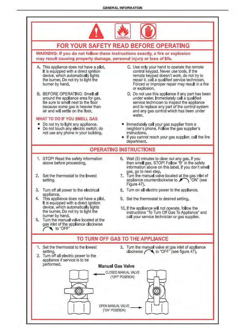
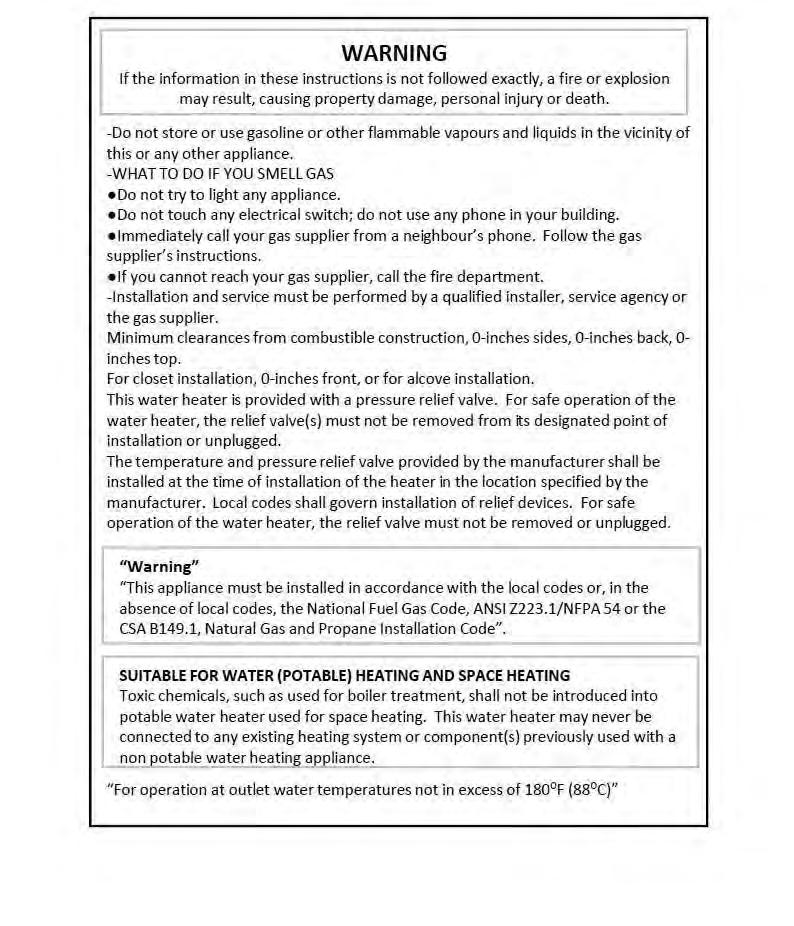
1 Instruction Manual Installer: Affix these instructions adjacent to the boiler Homeowner: Retain these instructions for future reference PCH 34B-H Condensing Direct Vent Gas Boiler 116,000 BTU INPUT WARNING If the information in these instructions is not followed exactly, a fire or explosion may result, causing property damage, personal injury or death. - Do not store or use gasoline or other flammable vapors or liquids in the vicinity of this or any other appliance. - WHAT TO DO IF YOU SMELL GAS Do not try to light any appliance Do not touch any electrical switch; do not use any phone in your building Immediately call your gas supplier from a neighbor s phone. Follow the gas supplier s instructions. If you cannot reach your gas supplier, call the fire department -Installation and service be performed by a qualified installer, service agency or the gas supplier. -Use of a properly calibrated electronic combustion analyzer MUST be used to install and/or service this appliance. Approved in accordance with: ANSI Z21.13b-2010 / CSA 4.9b (2010) Low Pressure Boiler Manufactured/Distributed by : Granby Furnaces Inc Hwy 209, Parrsboro, NS, Canada
2 1. General information Pages 1.1 General warnings Product conformity 9 2. Technical characteristics 2.1 Technical data Dimensions Internal parts of the boiler Water circuit Circulation pump head/flow graph Printed circuit board Technical characteristics Control panel Information display Installation (authorized personnel) 3.1 Reference standard Unpacking Installation boiler Water connections Domestic Hot Water Circuit / Hard Water Warning / Expansion Tank Piping Diagram Condensate Drain Gas connection Electrical connections Venting connections Twin pipe venting Commissioning the appliance (authorized personnel) 4.1 General warnings Filling the system Flushing the system Filling the condensate trap Starting up the boiler Regulating the appliance (authorized personnel) 5.1 Parameters table Setting the parameters Gas Data Converting the Boiler to a Different Gas Type 55
3 6. Maintenance (authorized personnel) Pages 6.1 General warnings Maintenance Boiler inspection Accessing the boiler Flushing out the primary side Draining the central heating and domestic hot water system Maintenance operations Wiring diagrams D.H.W sensor connection Troubleshooting Diagnostics Parts list Cycle Sequence Flow Chart 73
4 1. GENERAL INFORMATION 1.1 General warnings Installation GENERAL INFORMATION Read all safety warnings in the Instruction Manual. The additional safety issues outlined below must also be followed completely when installing this Boiler. Use of a properly calibrated electronic combustion analyzer MUST be used when installing, servicing or converting this Boiler from Natural Gas to LP or from LP to Natural Gas. Failure to remove or maintain the area free of combustible material, gasoline and other flammable liquids or vapors can result in severe personal injury, death or substantial property damage. All applicable local, state, national and provincial codes, ordinances, regulations and laws must be observed. For installations in Massachusetts code requires the units to be installed by a licensed plumbing or gas fitter. If the hot water boiler is installed above radiation level or as required by the authority having jurisdiction, must be provided with a low water cutoff device at the time of boiler installation. Where required by the authority having jurisdiction, the installation must conform to the Standard for controls and safety devices for automatically fired boilers, ANSI/ASME CSD1. If an external electrical source is utilized, the appliance, when installed, must be electrically grounded in accordance with local codes or, in the absence of local codes, with the National Electrical Codes ANSI/NFPA 70 and or the CSA C22.1 Canadian Electrical Code. Follow all local codes and/or the most recent edition of the National Fuel Gas Code (ANSI Z223.1/NFPA 54) in the USA or the Natural Gas and Propane Installation Code in Canada (CAN/CSA B149.1). This unit is designed for indoor installations. DO NOT operate this unit without the vent piping connected. Exhaust gases must be completely expelled out of the building. Do not use this appliance if any part has been underwater. Immediately call a qualified service technician to inspect the appliance and replace any part of the control system and any gas control which has been underwater. Be sure not to reverse the water and gas connections as this may damage the gas valves. Water temperatures over 125 F can cause severe burns instantly or death from scalding. If the proposed boiler outlet temperature is above 125 F, a thermostatically controlled mixing valve (or a temperature limiting valve) for reducing point of use water temperature is recommended to reduce the risk of scald injury. Contact a licensed plumber or the local plumbing authority for further information. The appliance should be located in an area where leakage within the unit or at its connections will not result in damage to the area adjacent to the appliance or to lower floors of the structure. PENSOTTI will not be responsible for any damage resulting from leaking if adequate drainage is not provided. When such locations cannot be avoided, it is recommended that a suitable drain pan, adequately drained, be installed under the appliance. The flow of ventilation to the boiler must not be obstructed. The boiler area must be kept clear and free from combustible materials, gasoline and other flammable vapors and liquids. If the water quality is known to be highly acidic and/or extremely hard, water treatments (ie water softeners and filtration) are recommended to maintain full warranty. Consult the local water authority. DO NOT over-tighten fittings, as pipe and/or fitting damage may occur causing leakage. DO NOT install boiler where subject to vibrations. For other than a direct vent appliance, the appliance must be located as close as possible to a chimney or gas vent. Should overheating occur or the gas supply fails to shut off, turn the manual gas control valve to the appliance. Contact a Service Technician immediately. 1
5 GENERAL INFORMATION Clearance must be in accordance with the local installation codes and the requirements of the gas supplier. Never operate the heater unless it is vented to the outdoors and has adequate air supply to avoid risks of improper operation, fire, explosion or asphyxiation. DO NOT install this boiler directly on a carpeted floor. A fire hazard may result. The boiler shall be installed on a metal or wood panel extending beyond the full width and depth of the boiler by at least 3 inches (76.2mm) in any. For safe operation, an ample supply of air must be provided for proper combustion and ventilation in accordance with the National Fuel Gas Code ANSI Z223.1/NFPA 54 National Fuel Gas Code CSA/B149.1 Natural Gas and Propane Installation Codes or applicable provisions of the local building codes. An insufficient supply of air may result in a yellow, luminous burner flame, carboning or sooting of the heat exchanger, or create a risk of asphyxiation. Do not obstruct the flow of combustion and ventilation air. This unit is not intended to operate at gas supply pressures other than those shown on the rating plate. Exposure to higher gas supply pressure may cause damage to gas valves, which can result in fire or explosion. If overpressure has occurred, such as through improper testing of gas lines or emergency malfunction of the supply system, the gas valves must be checked for safe operation. A thermostatic mixing valve must be added to this system to prevent scalding, if regulated by local codes and authorities. Check the Rating Plate PENSOTTI units come from the factory configured for use with natural gas. Prior to installation, check the rating plate of the boiler to ensure the unit matches gas type, gas pressure, water pressure and electrical supply. If the unit does not match the requirements, do not install. Be sure the gas type and electricity voltage match the rating plate. There is a risk in using fuel burning appliances in rooms or areas where gasoline, other flammable liquids or engine-driven equipment or vehicles are stored, operated or are repaired. Flammable vapors are heavy and travel along the floor and may be ignited by the igniter or main burner flames causing fire or explosion. Some local codes permit operation of gas appliances if installed 18 inches or more above the floor. This may reduce the risk if location in such an area cannot be avoided. Flammable items, pressurized containers or any other potential fire hazardous articles must never be placed on or adjacent to the boiler. Open containers of flammable materials should not be stored or used in the same room with the boiler. Do not install the PENSOTTI boiler in areas with excessive high humidity. Do not install the unit in location where there is excessive humidity, such as a bathroom, damp crawl space, and other areas with high levels of humidity. This may cause the unit to malfunction. To avoid possible electrical shock, DO NOT touch the internal components of the boiler or the power cord with wet hands. DO NOT splash excessive water on the boiler when cleaning, as they are water resistant, not water proof. Professionally qualified personnel in accordance with current laws and standards and in line with the manufacturer s instructions must install the appliance. The commissioning of the boiler and any subsequent works carried out on the appliance must be effected by an appropriately qualified technician. The appliance must be used solely for the purpose for which it has been designed and manufactured: central heating and domestic hot water production. Any other use is deemed as improper and as such dangerous. Under no circumstances will the manufacturer be held responsible for damage or injury to persons or animals caused by errors in the installation and/or use of the appliance, or through non-compliance with current local and national standards and/or the manufacturer s instructions. The installation, operation and maintenance manual forms are an integral and essential part of the product and must be kept with the appliance always. The warnings contained in this chapter have been written for the appliance user, the installer and the service technician. 2
6 GENERAL INFORMATION The operating instructions chapter of this manual must be read carefully as it provides information on the operation and the operating limits of the appliance. After the removal of all the packaging, check that the appliance has not been damaged. In case of doubt, do not attempt to use the product but refer to the supplier. Packing materials (cardboard box, wooden crate, nails, staples, plastic bags, polystyrene, etc.) must not be left within reach of children in that these items represent a potential hazard and must be disposed of in a responsible manner. Before carrying out any cleaning or maintenance operations, disconnect the appliance from the mains electricity supply by switching off at the main switch and/or any other isolating device. In the case of a fault and/or malfunction in the appliance, shut down the system. Do not interfere with or attempt any repairs. Call for professionally qualified technical assistance only. Any warranty repairs to the appliance must be carried out exclusively by the manufacturer s authorized service dealers using original spare parts. Non-compliance with the above requirements may compromise the safety of the appliance and invalidate the warranty. In order to guarantee the efficiency of the appliance and its correct operation, it must be serviced regularly by professionally qualified personnel in line with the manufacturer s instructions. Only original accessories or optional extras (including electrical parts) must be used with the appliance. Should there be a smell of gas present in the room where the appliance is installed, DO NOT attempt to activate any electric switches, telephones or any other equipment that may cause sparks. Open doors and windows immediately to create a current of air and ventilate the room. Shut-off the main gas supply valve (at the meter), or on the cylinder in the case of bottled gas, and call an authorized service center. Do not attempt to interfere with the appliance in any way. As dictated by current legislation, this appliance must be installed exclusively by qualified personnel. Before starting the boiler for the first time, make sure that it is connected to a water supply and central heating system compatible with its performance characteristics. Prior to start-up, the central heating pipes should be flushed to remove any residues that could compromise the operation of the appliance. The appliance must be connected to a designated electrical circuit only. The power supply must be checked by a qualified electrician to ensure that it can support the maximum power absorption of the appliance, as indicated on the appliance rating plate (positioned on the casing). In particular, make sure that the cable ratings are adequate for the power absorbed. Do not use adapters; multiple sockets or extension leads to connect the appliance to the power supply. The appliance must be connected to the mains power supply through an appropriate electrical isolator in accordance with the current wiring regulations. If the cable is damaged in any way, switch off the appliance and have the cable replaced by a suitably qualified technician. When the appliance is no longer required for use, switch off the main power supply, to switch all electrical components off (circulating pump, burner etc.). The thermostats are adjusted at their minimum lowest temperature positions when shipped from the factory. Caution: Label all wires prior to disconnection when servicing controls. Wiring errors can cause improper and dangerous operation. The boiler piping system of a hot water boiler connected to heating coils located in air handling units where they may be exposed to refrigerated air circulation must be equipped with flow control valves or other automatic means to prevent gravity circulation of the boiler water during the cooling cycle. 3
7 GENERAL INFORMATION Important: Carbon Monoxide Detectors Many jurisdictions require the installation of carbon monoxide detectors in building where a side wall vented fuel burning appliance is installed. Installers must abide by local code requirements regarding the installation of CO detectors. The use of a certified carbon monoxide detector is recommended but not required by PENSOTTI. In the State of Massachusetts only (a)for all horizontally vented gas fuelled equipment installed in every dwelling, building or structure used in whole or in part for residential purposes, including those owned and operated by the Commonwealth and where the side wall exhaust vent termination is less than seven (7) feet above finished grade in the area of the venting, including but not limited to decks and porches, the following requirements shall be satisfied: 1. INSTALLATION OF CARBON MONOXIDE DETECTORS. At the time of installation of the side wall horizontal vented gas fuelled equipment, the installing plumber or gas fitter shall observe that a hard wired carbon monoxide detector with an alarm and battery back-up is installed on the floor level where the gas equipment is to be installed and on each additional level of the dwelling, building or structure served by the equipment. It shall be the responsibility of the property owner to secure the services of qualified licensed professionals for the installation of hard wired carbon monoxide detectors. a. In the event that the side wall horizontally vented gas fueled equipment is installed in a crawl space or an attic, the hard wired carbon monoxide detector with alarm and battery back-up may be installed on the next adjacent floor level. b. In the event that the requirements of this subdivision cannot be met at the time of completion of installation, the owner shall have a period of 30 days to comply with the above requirements; provided, however, that during said 30 day period a battery operated carbon monoxide detector with alarm shall be installed. 2. APPROVED CARBON MONOXIDE DETECTORS. Each carbon monoxide detector as required in accordance with the above provisions shall comply with NFPA 720 and be ANSI/UL 2034 listed and IAS certified. 3. SIGNAGE. A metal or plastic identification plate shall be permanently mounted to the exterior of the building at a minimum height of eight (8) feet above grade directly in line with the exhaust vent terminal for the horizontally vented gas fuelled heating appliance or equipment. The sign shall read, in print size no less than one-half (1/2) inch in size, GAS VENT DIRECTLY BELOW. KEEP CLEAR OF ALL OBSTRUCTIONS. 4. INSPECTION. The state or local gas inspector of the side wall horizontally vented gas fuelled equipment shall not approve the installation unless, upon inspection, the inspector observes carbon monoxide detectors and signage installed in accordance with the provisions of 248 CMR 5.08(2)(a) 1 through 4. 4
8 GENERAL INFORMATION 5

9 GENERAL Information ING 6
10 GENERAL Information 7
11 GENERAL Information 8
12 GENERAL INFORMATION 1.2 Product conformity All Granby/Pensotti LLC boilers are ETL certified and possess technical and functional characteristics that comply with the following standards: Gas fired Low Pressure Hot Water Boiler: American National Standard/CSA Standard for Gas Fired Low Pressure Steam and Hot Water Boiler. Certifies to ANSI STD Z21.13b, certified to CSA STD 4.9b. ASME Pressure vessel: The boiler includes a pressure vessel that is constructed in accordance with ASME and bears the H stamp. The materials used such as copper, brass, stainless steel, etc. form a compact, uniform, highly functional unit that is easy to install and simple to operate. In its simplicity, the wall-mounted appliance is equipped with all the appropriate accessories required to make it a fully independent boiler capable of satisfying domestic hot water production and central heating needs. This manual must be kept in a safe place and must accompany the boiler at all times. Granby/Pensotti LLC will not be held responsible for any misinterpretation of this manual resulting from the inaccurate translation of same. Granby/Pensotti LLC will not be held responsible for the consequences in the case of non-observance of the instructions contained in this manual or in the case where actions not specifically described herein are undertaken. 9
13 TECHNICAL CHARACTERISTCS 2. TECHNICAL CHARACTERISTICS 2.1 Technical data Model PCH 34B-H CE Certification n 0694BN3485 Appliance Type B23p-B33-C13-C33-C43-C53-C63-C83-C93 Appliance Category II2H3B/P Heat Input max kw - BTU/hr Heat Input min kw - BTU/hr Heat Output max - 122/86 F kw - BTU/hr Heat Output max - 176/140 F kw - BTU/hr Heat Output min - 176/140 F kw - BTU/hr AFUE % 91 Central Heating circuit Central Heating water temperature setting (min-max) C F / / Max. heating working temperature C F Expansion vessel capacity litres - gal Max. working pressure (heating) bar - psi Min. working pressure (heating) bar - psi Domestic Hot Water circuit D.H.W. temperature setting (min-max) C F Max. Hot water working pressure bar - psi 6 86 Min. Hot water working pressure bar - psi Dimensions (Boiler casing size) Width in 16.1 Height in 28.7 Depth in 12.2 Weight (net) lb 88 Hydraulic connections Central Heating Flow connection Soldier 3/4" Central heating Return connection Soldier 3/4" Central heating flow connection to DHW storage cylinder Soldier 3/4" Central heating return connection from DHW storage cylinder Soldier 3/4" Cold water mains connection Soldier 1/2" Gas connection NPT 1/2" Flue systems Horizontal-Concentric flue system Ø mm - in 80/ /5 Max. Flue length m - ft pipes non conecntric flue system (flue and air intake) See Table Section 3.11 Max. Flue length (from terminal to terminal 2 pipes) See Table Section 3.11 Gas Supply Natural gas G 20 Inlet pressure wc 6.0 min 9.0 max Propane G31 Inlet pressure wc 11.0 min 14.0 max Electrical specifications Power supply V/Hz 110/60 Electrical power consumption W 180 Electrical protection IP X4D 10
14 TECHNICAL CHARACTERISTCS 2.2 Dimensions LEGEND HR HEATING RETURN Ø 3/4" HF HEATING FLOW Ø 3/4" G GAS Ø 1/2" CWI COLD WATER INLET Ø 1/2" HWO HOT WATER OUTLET Ø 1/2" SC CONDENSATE DRAIN Ø 0.98 in 11
15 TECHNICAL CHARACTERISTCS 2.3 Internal parts of the boiler LEGEND 1. SAFETY THERMOFUSE 2. FLUE HOOD 3. PRIMARY CONDENSING HEAT EXCHANGER 4. IONISATION ELECTRODE 5. PREMIX BURNER UNIT (GAS MANIFOLD + BURNER) 6. CONDENSATE DRAIN PIPE 7. HEATING SENSOR 8. HEATING SAFETY THERMOSTAT 9. VENTURI 10. FAN 11. AUTOMATIC AIR VENT VALVE 12. PUMP 13. SAFETY VALVE 3/4 14. SYSTEM DRAIN VALVE 15. AUTOMATIC BY-PASS 16. AIR PRESSURE SWITCH 17. EXPANSION VESSEL 18. IGNITION TRANSFORMER 19. IGNITION ELECTRODE 20. ELECTRONIC GAS VALVE 21. ROOM SEAL CHAMBER BACK SIDE 22. LOW WATER CUT OUT SWITCH 23. CONDENSATE TRAP 24. DIVERTER VALVE ACTUATOR UL/CSA 25. NO-RETURN VALVE 26. WATER PRESSURE GAUGE 27. FILLING TAP
16 TECHNICAL CHARACTERISTCS 2.4 Water circuit REMOTO LCD EXTERNAL SENSOR G SC HR RCR RCF CWI HF STORAGE CYLINDER DHW TEMPERATURE SENSOR code 31368LA (SUPPLIED WITH THE BOILER) REMOTE DHW CYLINDER code 20045LA LEGEND 1. SAFETY THERMOFUSE 2. AIR PRESSURE SWITCH 3. HEATING SAFETY THERMOSTAT 4. HEATING SENSOR 5. PREMIX BURNER UNIT (GAS MANIFOLD+BURNER) 6. PRIMARY CONDENSING HEAT EXCHANGER 7. EXPANSION VESSEL 8. FAN 9. ELECTRONIC GAS VALVE 10. AUTOMATIC AIR VENT VALVE 11. PUMP 12. AIR VENT VALVE 1/4 13. SAFETY VALVE 3/4 14. FLUE HOOD 15. MAIN HEAT EXCHANGER 16. IGNITION TRANSFORMER 17. IGNITION ELECTRODE 18. IONISATION ELECTRODE 19. DIVERTER VALVE ACTUATOR UL/CSA 20. VENTURI 21. CONDENSATE TRAP 22. LOW WATER CUT OUT SWITCH 23. CONDENSATE DRAIN PIPE 24. FLOW LIMITER 25. FILLING TAP 26. WATER PRESSURE GAUGE 27. NO-RETURN VALVE LEGEND HR HF G RCR CWI RCF SC NOTE THERE IS A STRAINER ON THE HEATING CIRCUIT.. THE INSTALLATION OF AN ADDITIONAL STRAINER ON THE SECONDARY CIRCUIT IS RECOMMENDED. NON RETURN VALVE 4 bar SAFETY VALVE HEATING RETURN HEATING SUPPLY GAS CONTROL THERMOMETER MEMBRANE EXPANSION TANK, SEALED CHAMBER SHUTTER REMOTE D.H.W. CYLINDER RETURN COLD WATER INLET REMOTE D.H.W. CYLINDER FLOW CONDENSATE DRAIN 13
17 TECHNICAL CHARACTERISTCS 2.5 Circulation pump head/flow graph Head [ft] Water flow [US gpm] 14
18 TECHNICAL CHARACTERISTCS 2.6 DIGITECH printed circuit board SM Technical characteristics Adjustments possible by service personnel only Standard ( F) / reduced ( F) central h e a t i n g temperature Water hammer prevention function Central Heating timer - (adjustable from 0 to 7,5 minutes) Central Heating pump overrun timer Domestic Hot Water pump overrun timer Minimum Gas pressure setting Maximum Heating Load D.H.W. temperature setting F User settings On/Off Heating Temperature setting ( F) ( F) D.H.W. temperature setting ( F) ( F) D.H.W. only mode / Heat only mode / D.H.W. + Heat mode selection Operation/Functions display Lock-Out Water deficiency indicator Temperature display -+ When the boiler is switched off at the switch on the control panel, the word OFF appears on the display. The D.H.W and central heating frost protection system, nevertheless, remain enabled. If the boiler was previously on, it is switched off and the post-ventilation, pump overrun, circulation pump and three-way valve inactivity protection functions are enabled. 2.7 Control panel Control panel Key 1. HEATING TEMPERATURE SETTING BUTTONS 2. INFO BUTTON: PRESS ONCE TO DISPLAY TEMPERATURES AND INFO (see 2.8 INFO menu display). KEEP INFO BUTTON PRESSED FOR 5 SECONDS (in OFF MODE) TO DISPLAY THE LAST 5 ERRORS. 3. MODE SELECTION BUTTON SUMMER ONLY / WINTER ONLY / SUMMER-WINTER / OFF. 4. RESET BUTTON: ERROR RESET FLUE TEST FUNCTION ACTIVATION (CHIMNEY-SWEEPER - KEEP IT PRESSED FOR 7 SECONDS). 5. DOMESTIC HOT WATER TEMPERATURE SETTING BUTTONS. KEEP BUTTONS + AND - PRESSED FOR 5 SECONDS TO ACTIVATE THE DISPLAY BACKLIT MODE FOR A CONTINUOUS PERIOD OF 10 MINUTES. 6. TERMINAL BLOCK FOR EXTERNAL WIRING. 7. LCD DISPLAY
19 TECHNICAL CHARACTERISTCS LCD DISPLAY ICONS KEY 1. PARAMETER NUMBER INFORMATION 2. PARAMETERS PROGRAMMING MODE ON 3. SOLAR PCB CONNECTION INFORMATION / SOLAR PANEL TEMPERATURE DISPLAY (d6) 4. SOLAR PUMP ON 5. STORAGE CYLINDER LOW LEVEL TEMPERATURE VISUALIZATION (d7) / STORAGE CYLINDER HIGH LEVEL TEMPERATURE VISUALIZATION (d8) 6. OUTDOOR TEMPERATURE SENSOR CONNECTED 7. TEMPERATURE / SET POINT / PARAMETER VALUE INFORMATION 8. OPEN THERM COMPONENTS COMMUNICATION CONNECTED (REMOTE CONTROL / ZONE MANAGEMENT CONTROL BOX) 9. WATER LOW PRESSURE INFORMATION (*) FLAME PRESENCE ON (3 POWER STEPS) 11. D.H.W. MODE ENABLED 12. RESETTABLE ERROR < 33% >33%<66% >66%<100% DISPLAY 13. OFF MODE 14. NOT RESETTABLE ERROR DISPLAY 15. HEATING MODE ENABLED (*) - During the boiler operation the display can show 3 different power levels according to the flame modulation of the boiler. (see flame icon/power % images) 16
20 TECHNICAL CHARACTERISTCS 2.8 INFO Menu display Press the INFO Button to display the boiler data. Once pressed, the parameter number will appear on the left side of the display and the associated parameter value will appear on the centre of the display. Use and buttons of Heating Temperature setting to scroll the list of available data. Press the INFO button to exit the display mode. The list of available display data is the following: Parameter Icon Description d00 DHW sensor temperature d01 Outdoor sensor temperature (only with sensor temperature connected) d02 Fan speed d03 Low temperature circuit sensor (only with Zone PCB connected) d04 Heating return sensor temperature (only with modulating pump connected) d05 Solar panel sensor temperature (only with Solar PCB connected) d06 Solar storage cylinder temperature (low level) (only with Solar PCB connected) d07 Solar storage cylinder temperature (high level) (only with Solar PCB connected) d08 Solar panel sensor temperature 2 [ only with Solar PCB connected ] (SCS2) d09 Extra Solar storage cylinder temperature [ only with Solar PCB connected ] (SBS3) 17
21 INSTALLATION INSTRUCTIONS 3. INSTALLATION (authorized personnel) 3.1 Reference standard Install in accordance with local building and electrical codes. Failure to install a gas appliance correctly and in accordance with the above norms could lead to prosecution. It is in the interest of the installer and safety that the codes are complied with. The manufacturer s instructions form an integral part of the installation and should be left with the appliance but do not over ride in anyway statutory obligations. Installation requirements Please refer to local and national standards in force with the Country of destination of the product. 18
22 INSTALLATION INSTRUCTIONS 3.2 Unpacking The materials (cardboard) used for packing the appliance are fully recyclable. It is recommended that the packing material is only removed prior to installing the boiler. The manufacturer will not be held responsible for damage caused by incorrect storage of the product. Packing materials (plastic bags, polystyrene, nails, etc.) must not be left within reach of children, in that these items represent a potential hazard. A. Place the packed appliance on the floor (see fig. 1) making sure that the "up arrow is facing down. Remove the staples and open out the four flaps of the box. B. Rotate the boiler 90 while manually supporting it from underneath C. Lift the box and remove the protections. Lift the boiler by grasping the rear part and proceed with the installation. A C B Fig 1 STORAGE & HANDLING Please note that prior to installation the Pensotti North America boilers should be stored in the horizontal position with no more than three boilers to a stack; Ensure that the boilers are stored in dry conditions and be aware that the carton is a two-man lift; 19
23 INSTALLATION INSTRUCTIONS 3.3 Installing the boiler. The appliance must be installed exclusively on a vertical solid wall capable of supporting its weight. The boiler should be fitted within the building unless otherwise protected by a suitable enclosure i.e. garage or outhouse. (The boiler may be fitted inside a cupboard) If the boiler is sited in an unheated enclosure then it is recommended to leave the ON/OFF switch always in ON position to give frost protection. If the boiler is installed in a room containing a bath or shower reference must be made to the relevant requirements. Appliance is approved for installation on combustible walls. A B X L Y H MINIMUM DISTANCES [INCHES] Model X Y L H A B PCC Fig. 1 In order to allow access to the interior of the boiler for maintenance purposes, it is important that the minimum distances indicated in figure 1 are respected. To make the installation easier, the boiler is supplied with a template to enable the pipe connections to be positioned prior to fixing the appliance to the wall. To install the appliance, proceed as follows (see fig. 2): a. Use a level (of not less than 24 long) to mark a horizontal line on the wall where the appliance is to be fitted. b. Position the top of the template along the line drawn with the level, respecting the distances indicated. Then mark the centres of the positions of the two wall screws or anchors. Finally, mark the positions of the water and gas pipes. c. Remove the template and install the domestic hot and cold water pipes, the gas supply pipe and the central heating pipes using the fittings supplied with the unit. Fix the boiler to the wall using the bracket and connect the pipes. Fig. 2 20
24 INSTALLATION INSTRUCTIONS 3.4 Water connections In order to safeguard the heat exchanger and circulation pump, especially in case of appliance replacement, it is recommended that the system is hot-flushed to remove any impurities (especially oil and grease) from the pipes and radiators. In order to safeguard all waterside components the supplied Fernox Commissioning Kit Must be used in its entirety Make sure that the domestic water and central heating pipes are not used to earth the electrical system. The pipes are totally unsuitable for this purpose. Isolation Valves must be installed on the heating and D.H.W circuits. This will facilitate all maintenance and service operations where the appliance needs to be drained. To prevent vibration and noise coming from the system, do not use pipes of reduced diameter, short radius elbows or severe reductions in the cross sections of the water passages. Fig RCR RCF HR G CWI HF In order to guarantee the reliability of the boiler a pressure reducing valve and backflow preventer must be installed. To facilitate the installation, the boiler is supplied with an hydraulic connection kit (see fig.2). RCR CWI HF RCF A pressure relief valve is installed in this dual purpose boiler that is rated in accordance with and complying with either The Standard for relief Valves and Automatic Shutoff Devices for Hot Water Supply Systems, AINSI Z21.22 or The ANSI/ASME Boiler and Pressure Vessel Code, Section IV (Heating Boilers).The relief valve must be installed such that the discharge will be conducted to a suitable place for disposal when relief occurs. The discharge line must be installed to allow complete drainage of both the valve and the line. If this unit is installed with a separate storage vessel, the separate vessel must have its own temperature and pressure relief valve. This valve must also comply with The Standard for Relief Valves and Automatic Shutoff Devices for Hot Water Supply Systems. AINSI Z21.22 (in the U.S. only). A temperature relief valve is not required but if one is used, do not install the valve with the probe directly in the flow of water. This may cause unwarranted discharge of the valve. HR Fig. 2 LEGEND HR HEATING RETURN Ø 3/4" HF HEATING SUPPLY Ø 3/4" G GAS Ø 1/2" RCR REMOTE D.H.W. CYLINDER RETURN Ø 3/4" RCF REMOTE D.H.W. CYLINDER FLOW Ø 3/4" CWI COLD WATER INLET Ø 1/2" SC CONDENSATE DRAIN Ø 0.98 in 19
25 3.5 Domestic Hot Water Circuit INSTALLATION INSTRUCTIONS In order to prevent scaling and eventual damage to the D.H.W heat exchanger, the mains water supply must not have a hardness rating of more than 7 grains/gal (120 ppm). It is nevertheless advisable to check the properties of the water supply and install the appropriate treatment devices where necessary. The cold water supply pressure at the inlet to the boiler must be between 7.25 psi (0.5 bar) and 87 psi (6 bar). In areas with higher water inlet pressure a pressure reducing valve must be fitted before the boiler. The frequency of the heat exchanger coil cleaning depends on the hardness of the mains water supply and the presence of residual solids or impurities, which are often present in the case of a new installation. If the characteristics of the mains water supply are such that require it to be treated, then the appropriate treatment devices must be installed, while in the case of residues, an in-line filter should be sufficient. Central heating circuit In order to prevent scaling or deposits in the primary heat exchanger, the mains supply water to the heating circuit must be treated according to the requirements of local standards. This treatment is indispensable in the case where the circuit is frequently topped-up or when the system is often either partially or fully drained. In order to safeguard all waterside components the supplied Fernox Commissioning Kit Must be used in its entirety. Condensate drain Refer to the city, town or municipality have jurisdiction for codes regarding the proper discharge of condensate. The condensate drain flexible pipe supplied with the boiler must be connected to a proper condensate trap. The condensate discharge into the drainage system is allowed providing a condensate trap (siphon) is installed. Any condensate discharge pipe work external to the building (or in an unheated part of it) must be insulated to protect against frost. Before switching the boiler On, check the correct condensate discharge. Expansion Tank Capacity Max. System Operating Temperature ( F) Maximum System Water Content (Gals.)* When installing this boiler without an indirect water heater the following precautions must be taken. Install the supplied piping spurs for an indirect boiler. Using ¾ copper pipe, connect the supply and return together. SEE drawing on next page. Set mode selection switch to Heat only position. SEE section 2.7 Change parameter 01 (P01) to a value of 00 20

26 3.6 Piping Diagrams INSTALLATION INSTRUCTIONS These piping diagrams are examples for illustrative purposes only. They are not designed to be used as a piping schematic. *Max. 4 pipe diameters between tees *External Low Water Cut-Off if required by local code *Tempering Valve May be Required Consult Local Codes *Must leave at least 15 of straight pipe on either side of closely spaced tees If NOT installing an indirect water heater directly to the boiler you must install a by-pass using the supplied indirect water heater connections. See page 20 for more information. 21


27 Pensotti requires the installation of a pressure reducing valve & backflow preventer with all Solenne Series boilers. INSTALLATION INSTRUCTIONS Dirt / Scale Separation Along with the application of our Fernox commissioning kit Pensotti highly recommends the installation of a dirt separator in the return piping of all Solenne Series boiler models. Follow the manufacturer s instructions when installing these devices. 22
28 3.7 Condensate drain INSTALLATION INSTRUCTIONS FAILURE TO INSTALL THE CONDENSATE DISCHARGE PIPEWORK CORRECTLY WILL AFFECT THE RELIABLE OPERATION OF THE DUAL PURPOSE BOILER. The condensate discharge pipe MUST NOT RISE at any point along its length. There MUST be a fall of AT LEAST 2.5 (1 per 20 ) along the entire run. I. The condensate outlet terminates in 7/8 nut and seal for the connection of 7/8 plastic overflow pipe which should generally discharge internally into the household drainage system. If this is not possible, discharge into an outside drain is acceptable. 2. Ensure condensate piping, neutralizer, and discharge of condensate complies with any and all local and national codes. 3. The discharge pipe should be run in a proprietary drain pipe material e.g. PVC, PVC-U, ABS, PVC-C or PP. 4. Metal pipe work is NOT suitable for use in condensate discharge systems. 5. The pipe should be a minimum of 7/8 diameter and must be supported using suitably spaced clips to prevent sagging. 6. Any pipe fitted externally must not exceed 10 feet. 7 Any condensate discharge pipe work external to the building (or in an unheated part of it e.g. garage) must be insulated to protect against frost. It is also recommended that the pipe diameter is increased to 1 ¼. 8. If the boiler is fitted in an unheated location the entire condensate discharge pipe should be treated as an external run. 9. In ali cases discharge pipe must be installed to aid disposal of the condensate. To reduce the risk of condensate being trapped, as few bends and fittings as possible should be used. 10. When discharging condensate into a soil stack or waste pipe the effects of existing plumbing must be considered. If soil pipes or waste pipes are subjected to internal pressure fluctuations when WC's are flushed or sinks emptied then back-pressure may force water out of the boiler trap and cause appliance lockout. Information Only: Examples are shown of the following methods of termination:- i) to an internal soil & vent pipe ii) via an internal discharge branch (e.g. sink waste) iii) to a drain or gully iv) to a purpose made soak away Ensure condensate piping, neutralizer, and discharge of condensate complies with any and all local and national codes. IF, FOR ANY REASON, THE CONDENSATE DRAINAGE SYSTEM FAILS AND CONDENSATE IS PERMITTED TO FLOW BACK INTO THE INTERNAL CONDENSATE BOTTLE INSIDE THE BOILER, THE BOILER WILL STOP AND WILL DISPLAY AN E01 ERROR. THE CONDENSATE DRAINAGE SYSTEM PROBLEM MUST THEN BE CORRECTED BEFORE THE BOILER IS PUT BACK IN OPERATION. Sink Boiler Boiler 1" per 20" of pipe run 2.5 Minimum fall Boiler 18" min 1" per 20" of pipe run 2.5 Minimum fall 1" per 20" of pipe run 2.5 Minimum fall Termination to an internal soil and vent pipe Boiler 1" per 20" of pipe run 2.5 Minimum fall External termination via internal discharge branch e.g. sink waste - downstream Pipe must terminate above water level but below surrounding surface External termination to a drain or gully Pipe must terminate above water level but below surrounding surface External termination to a purpose made soak-away 20" min Holes in the soak-away must face away from the building 23
29 INSTALLATION INSTRUCTIONS 3.8 Gas Connection Gas Piping Guidelines Follow all local codes and/or the most recent edition of the National Fuel Gas Code (ANSI Z223.1/NFPA 54) in the USA or the Natural Gas and Propane Installation Code in Canada (CAN/CSA B149.1) Gas Supply Lines Pressures The minimum and maximum inlet gas pressures are Natural Gas Min WC Max WC. and Propane Gas Min WC Max WC. Gas pressures over and above the specified range will result in adverse performance and dangerous operating conditions; any damage resulting from extreme gas supply pressures will not be covered by the limited warranty. Until pressure testing of the main gas supply line is completed, ensure the gas line to the PENSOTTI Boiler is disconnected to avoid any damage to the boiler. The appliance and its individual shut off valve must be disconnected from the gas supply piping system during any pressure testing of that system at test pressures in excess of 0.5 psi (3.5 kpa).. The appliance must be isolated from the gas supply piping system by closing its individual manual shut-off valve during any pressure testing of the gas supply system at test pressures equal to or less that 0.5 psi (3.5 kpa). The gas appliance and its gas connections must be leak tested before placing the appliance in operation. Leaks can be found by using a gas leak detection device or by applying soapy water to all gas fittings. Should bubbles occur, tighten those connections and re-test. Always purge the gas line for any debris before connecting to the boiler gas inlet. Never use an open flame to test for gas leaks as property damage, personal injury or death could result. The maximum inlet gas pressure must not exceed the valve specified by the manufacturer and that the minimum valve listed as for the purposes of input adjustment. The connection to the gas supply must be carried out by professionally qualified personnel in accordance with the relevant standards. Check the internal and external seals of the gas supply system. A gas shut-off valve and sediment trap must be installed upstream of the appliance. Before starting up the boiler, make sure that the type of gas corresponds to that for which the appliance has been set-up. The gas supply pressure must be between the values reported on the rating plate. Conversion of the appliance from natural gas to LPG or vice versa must be carried out by qualified personnel. The power supply cable must be replaced by a qualified electrician. If the cable is damaged in any way, switch off the appliance and have the cable replaced by a suitably qualified electrician. When using an electrical appliance, a few fundamental rules must be observed: Do not touch the appliance with damp or wet parts of the body or when barefoot. Do not pull on the electric wires. Do not allow the appliance to be used by children or anyone unfamiliar with its operation. 24
30 INSTALLATION INSTRUCTIONS Length of Pipe In Feet Natural Gas Pipe Sizing Chart Size of Schd. 40 Black Iron Pipe in Inches 1/2" 3/4" 1" 1-1/4" 1-1/2" 2" Natural Gas flow is given in thousands of BTU/hr. - One cubic foot of natural gas = 1000 BTU Nominal pressure at the burner for Natural Gas is 3.5" of water column. (Typical machine supply 5"-7") Pipe length must include additional length for all fittings. Add approximately 5 feet of pipe per fitting Natural Gas Example: A machine with a burner that requires 440,000 BTU would need a 1-1/4" pipe for a 20' long run. Length of Pipe in Feet Liquid Propane Gas Pipe Sizing Chart Size of Schd. 40 Black Iron Pipe in Inches 1/2" 3/4" 1" 1-1/4" 1-1/2" 2" LP Gas flow is given in thousands of BTU/hr. - One cubic foot of LP gas BTU This chart refers to low pressure LP, after regulation Standard nominal pressure at the burner for Liquid Propane Gas is 11" of water column. Pipe length must include additional length for all fittings. Add approximately 5 feet of pipe per fitting LP Example: A machine with a burner that requires 440,000 BTU would need a 1" pipe for a 20' long run. Make sure the boiler is operating normally. Shut down the unit by pressing the ON/OFF button on the control panel. Remove the front panel and disconnect the flame rod sensor. Restart the boiler. The burner should light but shut down after a few seconds. If that is the case, the system is OK. It the burner does not shut down, push the ON/OFF switch to shut down the boiler and perform a troubleshooting procedure. 25
31 INSTALLATION INSTRUCTIONS 3.9 Electrical connections General warnings Follow the electrical code requirements of the local authority having jurisdiction. In the absence of such requirements, follow the latest edition of the National Electrical Code (NFPA 70) in the U.S. or the latest edition of CGA C22.1 Canadian Electrical Code Part 1 in Canada Electric Wiring: Ground and Surges All units come with factory installed 3-pronged (grounded) plug end. The boiler can be plugged into any standard electrical duplex outlet close to the unit as it requires only 4 Amps. If the local jurisdiction requires the unit to be wired directly, remove and discard the factory installed plug. An ON/OFF switch controlling the main power between the breaker and the Boiler should be provided to facilitate end-user maintenance and servicing. This should be done by a qualified electrician. The boiler must be electrically grounded. Ensure the electrical receptacle, in which the boiler will be plugged into, is properly grounded; if wiring directly, do not attach the ground wire to either the gas or the water piping as plastic pipe or dielectric unions may isolate the boiler electrically. The use of a surge protector, surge capacitor, line conditioner or equivalent is recommended to protect the appliance from power surges. If a generator is to be used as backup power care must be taken that a line conditioner is used to protect the appliance from erratic voltage. If the boiler is to be installed in a structure utilizing a emergency stand-by generator, the installation of a surge capacitor, surge protector, line conditioner or equivalent is required. If the boiler is to be installed in a structure where frequent power outages are experienced the installation of a surge capacitor, surge protector, line conditioner or equivalent is required. Do not energize electric power to the unit until all plumbing and gas piping is complete and the boiler has been filled with water. The electrical supply required by the boiler is 120VAC at 60Hz with a maximum 4A rating with proper grounding. Protection must be in place to prevent the Boiler from being exposed to voltage in excess of 130VAC Max or 95VAC Min. Damage caused by excessive voltage is not covered under warranty. DO NOT connect VAC and any other voltage to this PENSOTTI Boiler. This will damage the boiler and void the warranty. Do not disconnect the power supply when the unit is in normal operation. If there is a power failure in cold weather areas, the freeze prevention system in the boiler will not operate and may result in freezing of the heat exchanger; in cold weather areas where power failures are common, you must completely drain the unit to prevent damage if the power will be off for any extended period of time. Damage caused by freezing is not covered under warranty. CAUTION : Label all wires prior to disconnection when servicing controls. Wiring errors can cause improper and dangerous operation. Verify proper operation after servicing. The connection to the main power supply must be carried out by professionally qualified electrical personnel, registered in accordance with current legislation and local authorities. 25
32 INSTALLATION INSTRUCTIONS Always check to make sure that the appliance has an efficient ground system. This requirement is only satisfied if it has been properly connected to an efficient ground system installed in accordance with the requirements of current safety standards and carried out by professionally qualified personnel. This basic safety measure must be checked, verified and carried out by professionally qualified personnel. Have the electrical system checked by a qualified electrician. The manufacturer will not be held liable for any damage or injury caused as a result of an inefficient or faulty ground system. Ensure the domestic power supply is checked by a qualified electrician to ensure that it can support the maximum power absorption of the appliance, as indicated on the rating plate. In particular, make sure that the cable sizes are adequate for the power absorbed by the appliance; The power supply cable must be replaced by a qualified electrician. If the cable is damaged in any way, switch off the appliance and have the cable replaced by a suitably qualified electrician; When using an electrical appliance, a few fundamental rules must be observed: Do not touch the appliance with damp or wet parts of the body or when barefoot. Do not pull on the electric wires. Do not allow the appliance to be used by children or anyone unfamiliar with its operation; If the unit fails to re-start after any fault, unplug the unit for 30 seconds, then re-plug in the unit and try to restart with the on/off switch. If the unit fails to restart, call a qualified Technician for service. 26
33 INSTALLATION INSTRUCTIONS Remote control connection Connect the power supply to the terminal board inside the control panel as follows: a. Switch off the power supply at service switch or breaker. b. Remove the front case panel of the boiler. c. Slacken the screws and remove plate A (see fig. 1). d. With the plate removed, connect the wires to the terminal board B as follows: Connect the earth wire (normally coloured green/yellow) to the terminal marked with the earth symbol. Connect the neutral wire (normally coloured blue) to the terminal marked with the letter N. Connect the live wire (normally coloured brown) to the terminal marked with the letter L. Terminals identified by the letters: Ta Room thermostat or End Switch Se Outside temperature sensor Ta terminals are 24V DC. Only a non-power robbing, battery operated thermostat or dry set of contacts can be installed on Ta terminals. When the wires have been connected, place plate A" back to position. Switch the power supply back on. Se Se Ta A B L N Ta blue yellow/green brown Fig. 1 27
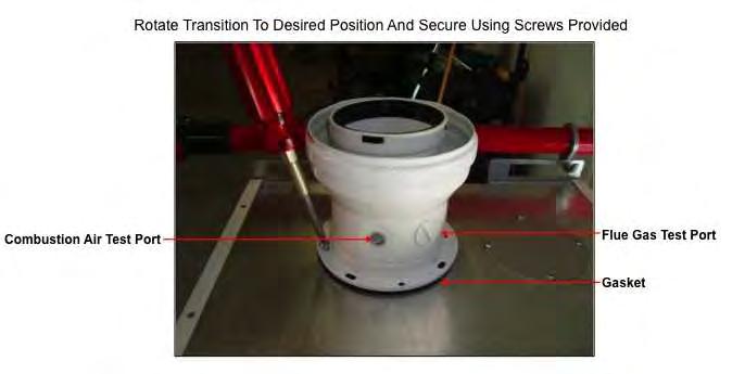
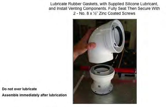
34 INSTALLATION INSTRUCTIONS 3.10 Venting Improper venting of boiler can result in excessive levels of carbon monoxide which can result in severe personal injury or death. This boiler must be vented in accordance with the Venting of Equipment section of the latest edition of the ANSI Z223.1 / NFPA 54 Natural Gas Code and/or the Venting systems and air supply for appliances section of the latest version of the CAN/CSA B149.1 Natural Gas and Propane Installation Code in Canada and in accordance with all applicable local building codes. Venting Guidelines For best results, keep the vent system as short and straight as possible. Locate the boiler as close as possible to the vent termination. The boiler vent must not be common vented with any other gas appliance or vent stack. Slope vent upwards towards the vent terminal at a rate of 1/8 per foot (1% slope). Vent termination must be a minimum of 12 above grade or expected snowfall. Vent and air intake pipe must be supported every 4 feet of horizontal run and every 5 feet of vertical run. PENSOTTI and Direct Vent All PENSOTTI boilers are prepared at the factory to be direct vent (sealed combustion) units which draw all of their required combustible air directly from outside the building. All PENSOTTI boilers use a 3/5 concentric vent or a 2 pipes system that uses a 3 diameter exhaust and a 3 diameter air intake pipe. Use only vent and air intake systems certified with the boiler. The air intake vent materials can be made of ABS, CPVC, PVC materials and in accordance with all applicable local building codes. Contaminated Make-Up Air Will Damage the Unit We recommend not operating the boiler in an area that is or will be under construction or renovation. The PENSOTTI warranty will not cover damage and premature wear caused to the unit due to installation in a contaminated environment. All exhaust venting connections must be leak checked with a soap solution upon initial start up of the boiler. Any leaks must be repaired before continuing operation of the boiler. All concentric venting must be checking for cross contamination using a combustion analyzer inserted into the makeup air test port on the venting adapter. Analyzer must NOT read anything in excess of 0 ppm Carbon Monoxide (CO). Any leaks must be repaired before continuing operation of the boiler. Warranty will not be available if the boiler is used for construction heat. 28

35 INSTALLATION INSTRUCTIONS Venting Pictures & Illustrations 29
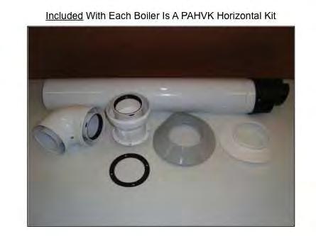
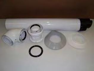
36 INSTALLATION INSTRUCTIONS Included With Each Combination Boiler Is A PAHVK Horizontal Kit 30

37 INSTALLATION INSTRUCTIONS 12 Clearance Suggested From The Top Of The Appliance To Ceiling 10 7 ¾ Top of Appliance to Center Line Of Hole 31
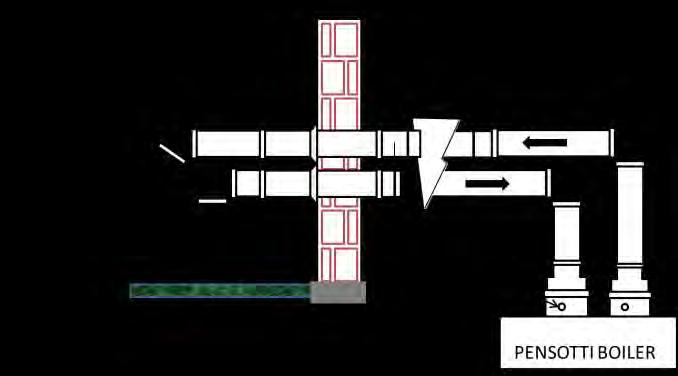
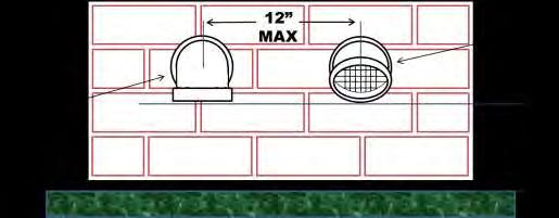
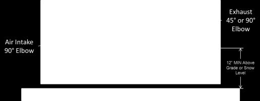
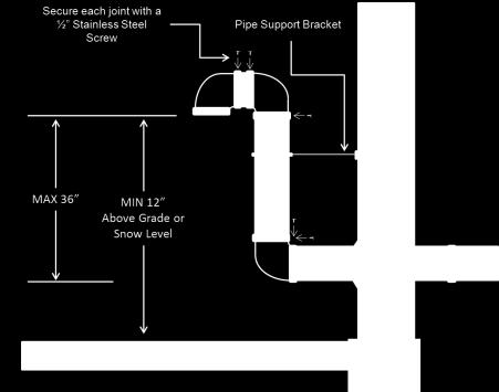
38 INSTALLATION INSTRUCTIONS Pipes Venting system Pictures & Illustrations The two pipes direct vent system can be installed in one of the following configurations. 1. Air Intake & Exhaust Pipes on an outside horizontal wall (intake and vent adjacent) 2. Air Intake & Exhaust Pipes on an outside vertical wall / roof (intake and vent adjacent) Exhaust piping material Polypropylene Pipe (UL 1738) rated for a maximum temperature of 230 F Combustion air piping material Polypropylene (UL 1738) PVC (Schedule 40, ANSI/ASTM D2661, ULC S102.2) CPVC (Schedule 40, ANSI/ASTM D2661, ULC S102.2) Installation Guidelines Do not allow any low points in the exhaust vent system unless a proper drain fitting is used to allow condensate to be removed. Install exhaust vent pipe directly as possible with as few elbows as possible. Condensate must drain from the exhaust pipe back to the boiler. Pitch the exhaust pipe approximately 5/8 per linear foot back towards the boiler. A hacksaw or equivalent can be used to cut the vent pipe if necessary. Once cut be sure to file the cut edges to remove all burs. Be sure not to deform the pipe. All piping must be securely supported. Use approved vent pipe hangers at a minimum of 48 intervals to prevent pipes from sagging. When utilizing a vertical exhaust system install the approved vent pipe hangers to support the entire weight, the boiler is not designed to support the weight of any venting system. (Contact your local vent material supplier for more specific ins tallation information). Assemble all vent materials in a way that prevents the accumulation of condensate. Be sure not to exceed the maximum total equivalent length of the direct vent system as indicated in this manual. See table below. A maximum of 7 90 elbows may be installed in the complete intake air / exhaust vent system. When using PVC or CPVC fittings long sweep elbows are recommended. The venting system must be installed by a licensed, professional heating contractor who is familiar with the installation and operation of heating appliances and venting systems. The venting system must be installed in accordance with all local, state and national codes. To ensure continued safe operation of the boiler, the venting system must be accessible for inspection once a year by a qualified technician. The air intake and flue exhaust terminations should be located on a wall that is least affected by prevailing winds (high winds may affect boiler operations). Do not use adhesives of any kind with polypropylene vent materials. All venting must be secured using the manufacturer s flue pipe clamps. If using PVC or CPVC for combustion air piping an approved solvent and cement must be used (ANSI/ASTM D2564). Only use in well ventilated areas. Vent Termination Requirements The vent system must be installed according to all local, state and national regulations. Including ANSI-Z223.1 or NFPA 54. The vent must not terminate less than 7 feet above a paved sidewalk or driveway located on public property. The vent pipe must not terminate within 4 feet horizontally of a gas regulator vent, electrical meter, gas meter or any relief equipment. The vent must not terminate less than 1 foot grade level or anticipated snow level. The vent must not terminate within 1 foot of any window or door which can be opened, any nonmechanical air supply inlet. The vent must not terminate where condensate will cause problems. The vent must not terminate in a location where ice formation could cause a hazard. The vent must not terminate so that flue gases are directed towards structures in such a manner that it may cause property damage or personal injury. 32


39 INSTALLATION INSTRUCTIONS The vent must not terminate within 3 feet of a property line (check with local authorities in your area). The vent pipe must terminate at least 3 feet above any forced air inlet within 10 feet. The vent pipe must terminate at least 3 feet from any non-mechanical air supply inlet or the combustion air inlet to any other appliance. The vent must not terminate within 3 feet from an inside corner on an outside wall. See the Installation guideline diagram on the next page. Maximum allowable equivalent vent length Horizontal and Vertical systems. Boiler Model Number Vent Size Maximum Combined Equivalent length * Vent Size Maximum Combined Equivalent length * PCH 18B-H, PCI 18/8-H 2 50 ( 25 air intake + 25 exhaust) (95 air intake + 95 exhaust) PCH 34B-H, PCC 34-H, PCI 34/20-H 2 40 (20 air intake + 20 exhaust) ( 75 air intake + 75 exhaust) PCH 50B-H 2 24 (12 air intake + 12 exhaust) ( 75 air intake + 75 exhaust) * The vent system must be balanced (the air intake pipe and the exhaust pipe must be as close to equal in length as possible). A maximum of 7 elbows is may be installed in the entire venting system. Fittings equivalent length table Material 90 Elbow Long Sweep 45 Elbow 87 Elbow Polypropylene PVC/CPVC* *If standard 90 PVC/CPVC elbows are used the equivalent length is 8 per 90 elbow. FOR EXHUAST VENT PIPE MATERIAL: USE ONLY APPROVED POLYPROPYLENE EXHAUST PIPE. DO NOT USE GALVANIZED PIPE, PLASTIC PIPE OR CHIMNEY LINERS, RIDGED OR FLEXIBLE, OF ANY KIND. All polypropylene pipe exposed to sunlight must be UV approved pipe this includes all sidewall and vertical terminations both air intake and exhaust. Both the exhaust and air intake vent pipes must be the same size pipe. Clearance to combustibles on the approved polypropylene vent pipe is 0. 33
40 INSTALLATION INSTRUCTIONS 34

41 INSTALLATION INSTRUCTIONS 35

42 INSTALLATION INSTRUCTIONS The termination shall be located no less than 48 above or to the side of the exhaust for any other oil, gas or solid fuel appliance 36
43 INSTALLATION INSTRUCTIONS 4. COMMISSIONING THE APPLIANCE 4.1 General warnings The following operations must be carried out by professionally qualified personnel, registered in accordance with current legislation. Use of a properly calibrated electronic combustion analyzer MUST be used when installing, servicing or converting this Boiler from Natural Gas to LP or from LP to Natural Gas. The boiler leaves the factory pre-set and tested for burning either Natural Gas or LPG. Nevertheless, when starting the boiler for the first time, make sure that the information on the rating plate corresponds to the type of gas being supplied to the boiler. Once the system has been filled and the necessary adjustments made, remember to tighten the screws of the gas valve test point and make sure that there are no gas leaks from the test point and from any pipe fittings upstream of the gas valve. Preliminary operations Switching the boiler on for the first time means checking that the installation, regulation and operation of the appliance are correct: Check that the rating on the rating plate corresponds to that of the mains supply networks (gas, electricity, water)); Check that the power supply voltage to the boiler complies with the rating plate (120 V 60 Hz) and that the live, neutral and ground wires are connected properly. Also make sure that the ground connection is sound; Check that the gas supply is correctly sized for the flow rate required by the boiler and that it is fitted with all the safety and control devices stipulated by current regulations; Check that the supply of combustion air and exhaust and condensate discharge systems are functioning correctly and in line with current law and national and local standards; Check for the presence of permanent aeration/ventilation openings as required by current law for the type of appliances installed; Check that the exhaust vent and its connections to the termination comply with the requirements of current law and national and local standards for the type of appliances installed; Make sure that any central heating shut-off valves are open; Check that the condensate drain system, including outside the boiler (exhaust system condensate collection devices), allows the condensate to flow freely to the drain. Check that there are no flammable materials or liquids in the immediate vicinity of the boiler; Flush out both primary and domestic hot water circuits (see 4.3 Flushing the system ). 37
44 INSTALLATION INSTRUCTIONS 4.2 Filling the system Check the properties of the water supply and install the appropriate treatment devices if the mains water has a hardness rating more than 7 grains/gal. (120 ppm) in order to prevent scaling and eventual damage to the D.H.W heat exchanger. A pressure reducing valve and backflow preventer must be installed. AIR VENT VALVE PLUG PUMP PUMP PLUG Use only clean tap water to fill the system. Once the water pipes have been connected, close the gas feed valve and fill the system as follows: Check that the circulation pump runs freely; Check that the plug of the air vent valve has been slackened slightly to allow air to escape from the system (fig.1); Purge all air from primary heat exchanger using the manual air vent. Open the main domestic water supply valve; Open the filling tap R (fig. 2); Unscrew the plug on the pump to remove any trapped air, check that the pump is free then re-tighten it when water starts to flow out (fig.1); Before switching on the boiler, purge air completely from the air vent valve positioned on the top of the condensing exchanger (fig. 3) Open the air vents on the radiators and monitor the air evacuation process. When water starts to flow out of the radiators, close the air vents; Use the pressure gauge M (fig. 2) to check that the system pressure reaches the middle of the green section (14.5 psi = 1 bar) and that the code H2O does NOT appear on the control panel display (see 2.7 section Control Panel ); On completion, make sure that the filling tap R is perfectly closed R M Emptying the central heating system Whenever it is necessary to empty the system, proceed as follows: GREEN SECTION turn off the main power supply switch; wait for the appliance to cool down; turn the system drain tap RS (see fig. 2) and use a container to collect the water that runs out; Emptying the domestic hot water system Whenever there is danger of freezing or any other occurrence, the hot water system could be emptied in the following way: Shut off the water at the mains; Open all hot and cold water taps; Empty from the lowest point (where possible) psi = 1.5 bar 14.5 psi = 1 bar 7.2 psi = 0.5 bar 4 43 psi = 3 bar 38
45 REGULATION INSTRUCTIONS 4.3 Flushing the system Failure to flush and add inhibitor to the system will invalidate the appliance warranty. All systems must be thoroughly drained and flushed using additives corrosion inhibitors and flushing agents/descalers. Pensotti requires the use of the supplied Fernox Commissioning Kit or individual containers of Fernox F3 or F5 cleaner and F1 protector. Follow Fernox installation instructions. Failure to use Fernox F3 or F5 cleaner and F1 protector could void the warranty for all waterside components. To flush out the primary side of this unit a. Fill the boiler as per the filling instructions. b. Using a drain off cock on the lowest point of the system allow the water to drain from the system and boiler. c. In order to flush the system correctly turn off all radiators open the filling loop and drain cock simultaneously and allow the water to flow through the boiler. d. Open each individual radiator allowing water to flow through then turn that radiator off and repeat for all radiators on the system. e. Turn off the filling loop and close the drain cock open all radiators and open the filling to fill the system. f. Continue to fill the system until the pressure gauge reads in the Green section of the gauge (14.5 psi = 1 bar). To flush out domestic hot water circuit a. Open all hot water outlets. b. Turn on inlet group supply so water enters the boiler; leave to fill until water is released from the hot water outlets. Turn off all hot water outlets. c. Connect a hosepipe to the cylinder drain cock and open the drain cock. d. Allow water to flow through the boiler and out of the drain cock. e. Turn off water supply, disconnect the hosepipe, close the drain cock and refill the boiler. 4.4 Filling the condensate trap The condensation trap must be pre-filled when starting the boiler for the first time in order to prevent flue gases from flowing back through the trap. The filling operation is carried out as follows (see fig. 1): Remove plug T and fill the trap S three quarters full with water; Replace plug T and connect the drainpipe P into a condensate discharge trap conforming to current legislation; T S Attention! It is recommended to clean the condensate trap, after a few months of appliance operation, to remove deposits/residuals left after the first condensate passage within the units new components that may interfere with the correct operation of the trap itself. Fig. 1 39

46 REGULATION INSTRUCTIONS 4.5 Starting up the boiler Once the system has been filled, proceed as follows: Check that the exhaust flue is free of obstructions and correctly connected to the boiler; Switch on the power supply to the appliance; Open the gas isolation valve; Place switch 1 in the ON position (see 2.7 Control Panel ), after a few seconds the circulating pump will start to run; Use button 6 to set the D.H.W, Table n 1 HEAT or D.H.W./HEAT function. The symbols (fixed light) to indicate that the boiler is working; will light up The automatic ignition system will then light the burner. This operation is repeated for 3 times. It may however be necessary to repeat the operation in order to eliminate all the air from the gas pipes. To repeat the operation, wait approximately three minutes before re-attempting to light the boiler. To reset the boiler Switch off switch 1 (see 2.7 Control Panel ) and switch it back on again and repeat the lighting procedure; With the boiler ignited, if the system still emits noises, the operations must be repeated until all the air has been removed from the gas piping; Check the water pressure in the system. If the pressure has fallen, introduce water into the appliance until the code H2O disappears on the display and the pressure gauge reads in the Green section of the gauge (14.5 psi = 1 bar) on completion; Check gas pressure at gas valve inlet pressure tap. SEE Fig 2. Set gas pressure to proper level at the regulator (Refer to section 2.1 Technical Data). Gas pressure adjustments must be performed while the appliance is in Flue Test Function mode (maximum firing rate). Allow the boiler to fire in the heat mode. Press and hold the S button until 07 flashes on the screen. Do NOT make any adjustments to the gas valve itself. Unscrew the plug and insert an analyser in the exhaust sampling point PF, SEE Fig. 1, (air intake manifold is missing in the drawing to provide a clear view of the V screw) to check the CO2 value. Make sure that the value complies with that reported in table 1 while the appliance is in Flue Test Function mode; If the CO2 value does not correspond to the specified value, adjust screw V (see fig. 1) on the venturi clockwise to reduce the CO2 value or counter-clockwise to increase it; Gas type CO2 % Natural Gas - G Liquid Propane Gas - G Inlet Pressure Tap Fig 1. Fi g. 1 PF V Fig 2. 40
47 REGULATION INSTRUCTIONS 5. REGULATING THE APPLIANCE 5.1 Parameters table PARAMETER N TYPE OF OPERATION PARAMETER VALUE FUNCTION P00 Selects the model of boiler P01 P02 P03 Selects the type of boiler Selects the type of gas supply Sets the central heating temperature P04 Heating output rising time P05 P06 Water hammer prevention function D.H.W priority function P07 Central heating timer P08 P09 P10 Central heating pump overrun timer D.H.W/Storage cylinder pump overrun timer Minimum fan speed DHW Hz (Nat Gas) 60 Hz (Propane) 01 = 18 KW 04 = 34 kw 05 = 50 kw All other numbers NA 00 = NA 01 = PCC = PCI 18/8, PCI 34/20 03 = PCH 18/B, PCH 34/B, PCH 50/B 04 = NA 05 = Only heating boiler Natural gas LPG NA Standard ( F) Reduced ( F) 00 = 0 seconds (Disabled) 01 = 50 seconds (Default) 02 = 100 seconds 03 = 200 seconds 04 = 400 seconds Off (default) On Off On Displayed in multiples of 5 seconds (default value 36 x 5 = 180 ) Displayed in multiples of 5 seconds (default value 36 x 5 = 180 ) Displayed in multiples of 5 seconds (default value 18 x 5 = 90 ) Displayed in hertz (1Hz = 30 rpm) P11 Maximum fan speed - DHW 155 Hz (Nat Gas) 143 Hz (Propane) Displayed in hertz (1Hz = 30 rpm) P12 Minimum fan speed Heating 60 Hz (Nat Gas) 60 Hz (Propane) Displayed in hertz (1Hz = 30 rpm) P13 Maximum fan speed Heating 155 Hz (Nat Gas) 143 Hz (Propane) Displayed in hertz (1Hz = 30 rpm) P14 Sets the ignition sequence 110 Hz (Nat Gas) 130 Hz (Propane) Displayed in hertz (1Hz = 30 rpm) P15 P16 P17 Legionella prevention function (for storage boilers only) Outdoor reset curve (w/outdoor temperature sensor only installation) Sets the temperature measurement unit Off On (default) See the graph in the parameter setting explanation C F 41
48 REGULATION INSTRUCTIONS PARAMETER N TYPE OF OPERATION PARAMETER VALUE FUNCTION P18 Sets the 0-10V industrial bus piloting = Disabled (default) 01 = Flow temperature control mode 02 = Burner output control mode P19 Central heating minimum set point Displayed in C P20 Central heating maximum set point Displayed in C P21 D.H.W maximum set point Displayed in C P22 P23 P24 P25 T set point T flow / T return (w/modulating pump and return temperature sensor connected only) Modulating pump minimum speed (w/modulating pump and return temperature sensor connected only) Modulating pump maximum speed (w/modulating pump and return temperature sensor connected only) T timing T flow / T return (w/modulating pump and return temperature sensor connected only) = Disabled (default) Displayed in C Displayed in percentage Displayed in percentage Displayed in seconds NOTES: P04 - This parameter allows to modify the time the boiler takes (in heating mode) to reach the maximum power set. P10, P11, P12 - These parameters are automatically set according to the output value set in Parameter P00. P13 - The maximum boiler power, in heating mode, can be set according to the paragraph 5.5 Heating output (Kw) Fan frequency (Hz) diagram. 42
49 MAINTENANCE INSTRUCTIONS 5.2 Setting the parameters To modify the preset values of the parameters reported in the previous table, open the parameter settings menu as follows: 1. Place mode selection button in OFF position, visualized by symbol; 2. Keep pressed and buttons simultaneously and wait for symbol and P00, to appear on the display. P Release buttons and ; 4. Use and buttons of heating temperature setting to select the parameter to modify; P01 1 Adjust the value of the parameter using the procedure described in the following pages. 43
50 5.3 Setting the parameters MAINTENANCE INSTRUCTIONS PARAMETER P00 SELECTS THE MODEL OF BOILER P00 02 P00 03 To enter the parameters menu, follow the previously described procedure (see paragraph 5.2 Accessing the parameters menu - steps 1-4). 5. Use and buttons (D.H.W temperature setting) to modify the value of the parameter: 00 = 13 kw 01 = 18 KW 02 = 25 kw 03 = 28 kw 04 = 34 kw 05 = 50 kw 06 = 100 kw 6. Press mode selection button to confirm and to render the new parameter operative. 7. To exit from the parameters menu, press simultaneously and buttons. P01 P PARAMETER P01 SELECTS THE TYPE OF BOILER To enter the parameters menu, follow the previously described procedure (see paragraph 5.2 Accessing the parameters menu - steps 1-4). 5. Use and buttons (D.H.W temperature setting) to modify the value of the parameter: 00 = instantaneous boiler (w/dual circuit exchanger) 01 = instantaneous boiler (w/secondary d.h.w plate exchanger) 02 = storage cylinder boiler 03 = boiler with Comfort storage cylinder (+7 C) 04 = Comfort instantaneous boiler (w/secondary d.h.w plate exchanger and preheating function of plate heat exchanger) 05= only heating boiler 6. Press mode selection button to confirm and to render the new parameter operative. 7. To exit from the parameters menu, press simultaneously and buttons. P02 P PARAMETER P02 SELECTS THE TYPE OF GAS SUPPLY To enter the parameters menu, follow the previously described procedure (see paragraph 5.2 Accessing the parameters menu - steps 1-4). 5. Use and buttons (D.H.W temperature setting) to modify the value of the parameter: 00 = Natural Gas 01 = LPG 02 = G25 6. Press mode selection button to confirm and to render the new parameter operative. 7. To exit from the parameters menu, press simultaneously and buttons. 44
51 MAINTENANCE INSTRUCTIONS P03 00 PARAMETER P03 SETS THE CENTRAL HEATING TEMPERATURE To enter the parameters menu, follow the previously described procedure (see paragraph 5.2 Accessing the parameters menu - steps 1-4). 5. Use and buttons (D.H.W temperature setting) to modify the value of the parameter: 00 = standard ( F) 01 = reduced ( F) for under-floor heating P Press mode selection button to confirm and to render the new parameter operative. 7. To exit from the parameters menu, press simultaneously and buttons. P04 P PARAMETER P04 HEATING OUTPUT RISING TIME This parameter is used to set the time the boiler takes to reach the maximum power set, during the starting up. To enter the parameters menu, follow the previously described procedure (see paragraph 5.2 Accessing the parameters menu - steps 1-4). 5. Use and buttons (D.H.W temperature setting) to modify the value of the parameter: 00 = 0 seconds (disabled) 01 = 50 seconds (default) 02 = 100 seconds 03 = 200 seconds 04 = 400 seconds 6. Press mode selection button to confirm and to render the new parameter operative. 7. To exit from the parameters menu, press simultaneously and buttons. P05 P PARAMETER P05 WATER HAMMER PREVENTION FUNCTION Activating this function, the D.H.W contact is delayed for 2 seconds. To enter the parameters menu, follow the previously described procedure (see paragraph 5.2 Accessing the parameters menu - steps 1-4). 5. Use and buttons (D.H.W temperature setting) to modify the value of the parameter: 00 = Off 01 = On 6. Press mode selection button to confirm and to render the new parameter operative. 7. To exit from the parameters menu, press simultaneously and buttons. 45
52 MAINTENANCE INSTRUCTIONS P06 P06 P07 P PARAMETER P06 DHW PRIORITY FUNCTION This parameter is used to maintain the diverter valve on D.H.W mode for a time equal to the post-circulation, keeping hot the secondary heat exchanger. To enter the parameters menu, follow the previously described procedure (see paragraph 5.2 Accessing the parameters menu - steps 1-4). 5. Use and buttons (D.H.W temperature setting) to modify the value of the parameter: 00 = Off 01 = On 6. Press mode selection button to confirm and to render the new parameter operative. 7. To exit from the parameters menu, press simultaneously and buttons. PARAMETER P07 CENTRAL HEATING TIMER This parameter is used to set the minimum time in which the burner is kept switched off, once the heating flow temperature has exceeded the temperature set by the user. To enter the parameters menu, follow the previously described procedure (see paragraph 5.2 Accessing the parameters menu - steps 1-4). 5. Use and buttons (D.H.W temperature setting) to modify the value of the parameter within the prescribed limits (displayed in multiples of 5 seconds): min = 00 max = 90 For ex.: 90 = 90 x 5 = 450 (7,5 min) The default value is 36 = 180 = 3 min 6. Press mode selection button to confirm and to render the new parameter operative. 7. To exit from the parameters menu, press simultaneously and buttons. P08 36 PARAMETER P08 CENTRAL HEATING PUMP OVERRUN TIMER This parameter is used to set the pump functioning time, in heating mode, after switching off the main burner for the intervention of the room thermostat. To enter the parameters menu, follow the previously described procedure (see paragraph 5.2 Accessing the parameters menu - steps 1-4). P Use and buttons (D.H.W temperature setting) to modify the value of the parameter within the prescribed limits (displayed in multiples of 5 seconds): min = 00 max = 90 For ex.: 90 = 90 x 5 = 450 (7,5 min) The default value is 36 = 180 = 3 min 6. Press mode selection button to confirm and to render the new parameter operative. 7. To exit from the parameters menu, press simultaneously and buttons. 46
53 MAINTENANCE INSTRUCTIONS P09 18 P09 36 PARAMETER P09 D.H.W/STORAGE CYLINDER PUMP OVERRUN TIMER This parameter is used to set the pump functioning time, in D.H.W mode, after closing the water tap. To enter the parameters menu, follow the previously described procedure (see paragraph 5.2 Accessing the parameters menu - steps 1-4). 5. Use and buttons (D.H.W temperature setting) to modify the value of the parameter within the prescribed limits (displayed in multiples of 5 seconds): min = 00 max = 90 For ex.: 90 = 90 x 5 = 450 (7,5 min) The default value is 18 = 90 = 1.5 min 6. Press mode selection button to confirm and to render the new parameter operative. 7. To exit from the parameters menu, press simultaneously and buttons. P10 66 P10 67 PARAMETER P10 SETS THE MINIMUM FAN SPEED This parameter is used to set the minimum fan speed which corresponds to the minimum burner output. To enter the parameters menu, follow the previously described procedure (see paragraph 5.2 Accessing the parameters menu - steps 1-4). 5. Use and buttons (D.H.W temperature setting) to modify the value of the parameter within the prescribed limits (displayed in Hertz): min = 33 Hz max = Value set in parameter P11 The default value is set according to the output value set in Parameter P Press mode selection button to confirm and to render the new parameter operative. 7. To exit from the parameters menu, press simultaneously and buttons. P P PARAMETER P11 SETS THE MAXIMUM FAN SPEED This parameter is used to set the maximum fan speed which corresponds to the maximum burner output. To enter the parameters menu, follow the previously described procedure (see paragraph 5.2 Accessing the parameters menu - steps 1-4). 5. Use and buttons (D.H.W temperature setting) to modify the value of the parameter within the prescribed limits (displayed in Hertz): min = Value set in parameter P10 max = 203 Hz The default value is set according to the output value set in Parameter P Press mode selection button to confirm and to render the new parameter operative. 7. To exit from the parameters menu, press simultaneously and buttons. 47
54 MAINTENANCE INSTRUCTIONS P12 P PARAMETER P12 SETS THE MINIMUM FAN SPEED (CENTRAL HEATING) This parameter is used to set the minimum fan speed in heating mode, which corresponds to the minimum burner output during a heating mode request. To enter the parameters menu, follow the previously described procedure (see paragraph 5.2 Accessing the parameters menu - steps 1-4). 5. Use + and - buttons (D.H.W temperature setting) to modify the value of the parameter within the prescribed limits (displayed in Hertz): min = 33 Hz max = Value set in parameter P13 The default value is set according to the output value set in Parameter P Press the mode selection button to save any changes 7. To exit from the parameters menu, press simultaneously i and R buttons. P P PARAMETER P13 SETS THE MAXIMUM FAN SPEED (CENTRAL HEATING) This parameter is used to set the maximum fan speed in heating mode, which corresponds to the maximum burner output during a heating mode request [see paragraph 5.5 Heating output (kw) Fan frequency (Hz) diagram]. To enter the parameters menu, follow the previously described procedure (see paragraph 5.2 Accessing the parameters menu - steps 1-4). 5. Use + and - buttons (D.H.W temperature setting) to modify the value of the parameter within the prescribed limits (displayed in Hertz): min = Value set in parameter P12 max = 203 Hz The default value is set according to the output value set in Parameter P Press the mode selection button to save any changes 7. To exit from the parameters menu, press simultaneously i and R buttons. P14 90 P14 91 PARAMETER P14 SETS THE IGNITION SEQUENCE This parameter is used to set the fan speed during the starting up of the boiler. To enter the parameters menu, follow the previously described procedure (see paragraph 5.2 Accessing the parameters menu - steps 1-4). 5. Use + and - buttons (D.H.W temperature setting) to modify the value of the parameter within the prescribed limits (displayed in Hertz): min = Value set in parameter P10 max = 203 Hz The default value is set according to the output value set in Parameter P Press the mode selection button to save any changes 7. To exit from the parameters menu, press simultaneously i and R buttons. 48
55 MAINTENANCE INSTRUCTIONS P15 00 PARAMETER P15 LEGIONELLA PREVENTION FUNCTION (For storage boilers only) To enter the parameters menu, follow the previously described procedure (see paragraph 5.2 Accessing the parameters menu - steps 1-4). 5. Use + and - buttons (D.H.W temperature setting) to modify the value of the parameter: 00 = Off 01 = On (default) 6. Press the mode selection button to save any changes 7. To exit from the parameters menu, press simultaneously i and R buttons. P15 01 P16 P PARAMETER P16 SETS THE CLIMATIC COMPENSATION CURVE (w/outdoor temperature sensor installed) The d6.6 Electrical connections ) allows to automatically modify the flow temperature in accordance to the outdoor temperature. The factor governing the correction is the Kd thermoregulation value, indicating the flow temperature range selected (fig.1). The selection of the compensation curve is determined by the maximum flow temperature Tm and the minimum outdoor temperature Te taking into consideration the house insulation degree. The values of the flow temperature Tm, refer to standard F appliances or F for under-floor heating systems. The type of appliance can be set using parameter P03. To enter the parameters menu, follow the previously described procedure (see paragraph 5.2 Accessing the parameters menu - steps 1-4) and select parameter P Use + and - buttons (D.H.W temperature setting) to modify the value of the parameter within the range of setting from 00 to 30. The value corresponds to the graph curves in figure n Press the mode selection button to save any changes 7. To exit from the parameters menu, press simultaneously i and R buttons. Tm ( F) 113 MAX MIN 95 Kd = 15 Kd = 10 Kd = 5 Kd = 0 Kd = 20 Kd = 25 Kd = Te ( F) 95 49
56 MAINTENANCE INSTRUCTIONS P17 00 P17 01 PARAMETER P17 SETS THE TEMPERATURE MEASUREMENT UNIT This parameter is used to set the temperature measurement unit displayed: Celsius ( ) or Fahrenheit ( ) degrees. To enter the parameters menu, follow the previously described procedure (see paragraph 5.2 Accessing the parameters menu - steps 1-4). 5. Use + and - buttons (D.H.W temperature setting) to modify the value of the parameter: 00 = C 01 = F (default ) 6. Press the mode selection button to save any changes 7. To exit from the parameters menu, press simultaneously i and R buttons. P18 P PARAMETER P18 SETS THE 0-10V INDUSTRIAL BUS PILOTING This parameter is used to enable/disable the 0-10V industrial bus in order to set the burner output and the flow temperature by outdoor bus. To enter the parameters menu, follow the previously described procedure (see paragraph 5.2 Accessing the parameters menu - steps 1-4). 5. Use + and - buttons (D.H.W temperature setting) to modify the value of the parameter: 00 = Disabled (default) 01 = Flow temperature control mode 02 = Burner output control mode 6. Press the mode selection button to save any changes 7. To exit from the parameters menu, press simultaneously i and R buttons. P19 30 PARAMETER P19 CENTRAL HEATING MINIMUM SET POINT This parameter is used to set the central heating minimum user set point. To enter the parameters menu, follow the previously described procedure (see paragraph 5.2 Accessing the parameters menu - steps 1-4). 5. Use + and - buttons (D.H.W temperature setting) to modify the value of the parameter within the prescribed limits (displayed in Fahrenheit degrees): min = 68 F max = 104 F 6. Press the mode selection button to save any changes 7. To exit from the parameters menu, press simultaneously i and R buttons. P
57 MAINTENANCE INSTRUCTIONS P20 80 P20 75 PARAMETER P20 CENTRAL HEATING MAXIMUM SET POINT This parameter is used to set the central heating maximum user set point. To enter the parameters menu, follow the previously described procedure (see paragraph 5.2 Accessing the parameters menu - steps 1-4). 5. Use + and - buttons (D.H.W temperature setting) to modify the value of the parameter within the prescribed limits (displayed in Fahrenheit degrees): min = 104 F max = 190 F 6. Press the mode selection button to save any changes 7. To exit from the parameters menu, press simultaneously i and R buttons. P21 P PARAMETER P21 D.H.W. MAXIMUM SET POINT This parameter is used to set the D.H.W maximum user set point. To enter the parameters menu, follow the previously described procedure (see paragraph 5.2 Accessing the parameters menu - steps 1-4). 5. Use + and - buttons (D.H.W temperature setting) to modify the value of the parameter within the prescribed limits (displayed in Fahrenheit degrees): min = 113 F max = 167 F 6. Press the mode selection button to save any changes 7. To exit from the parameters menu, press simultaneously i and R buttons. P22 P PARAMETER P22 T SET POINT T FLOW / T RETURN (not applicable) This parameter is used to set the delta value between the flow and the return temperature. To enter the parameters menu, follow the previously described procedure (see paragraph 5.2 Accessing the parameters menu - steps 1-4). 5. Use + and - buttons (D.H.W temperature setting) to modify the value of the parameter within the prescribed limits (displayed in Fahrenheit degrees): 00 = Disabled (default) min = 10 C max = 40 C 6. Press the mode selection button to save any changes 7. To exit from the parameters menu, press simultaneously i and R buttons. 51
58 MAINTENANCE INSTRUCTIONS P23 P PARAMETER P23 MODULATING PUMP MINIMUM SPEED (not applicable) This parameter is used to set the minimum modulating pump speed during a heating mode request. To enter the parameters menu, follow the previously described procedure (see paragraph 5.2 Accessing the parameters menu - steps 1-4). 5. Use + and - buttons (D.H.W temperature setting) to modify the value of the parameter within the prescribed limits (displayed in percentage): min = 50 % max = 70 % 6. Press the mode selection button to save any changes 7. To exit from the parameters menu, press simultaneously i and R buttons. P24 P PARAMETER P24 MODULATING PUMP MAXIMUM SPEED (not applicable) This parameter is used to set the maximum modulating pump speed during a heating mode request. To enter the parameters menu, follow the previously described procedure (see paragraph 5.2 Accessing the parameters menu - steps 1-4). 5. Use + and - buttons (D.H.W temperature setting) to modify the value of the parameter within the prescribed limits (displayed in percentage): min = 70 % max = 100 % 6. Press the mode selection button to save any changes 7. To exit from the parameters menu, press simultaneously i and R buttons. P25 P PARAMETER P25 T TIMING T FLOW / T RETURN (not applicable) This parameter is used to set the timing response of the modulating pump. To enter the parameters menu, follow the previously described procedure (see paragraph 5.2 Accessing the parameters menu - steps 1-4). 5. Use + and - buttons (D.H.W temperature setting) to modify the value of the parameter within the prescribed limits (displayed in seconds): min = 20 max = Press the mode selection button to save any changes 7. To exit from the parameters menu, press simultaneously i and R buttons. 52
59 MAINTENANCE INSTRUCTIONS 5.3 Gas data Technical data tables Table no.1 - CO 2 Values Gas type CO 2 % Natural Gas Gas A 9.18 Liquid Propane Gas Gas E 10.3 Table no.2 - Frequency Gas type Minimum (Hz) Maximum (Hz) Natural Gas Gas A Liquid Propane Gas Gas E NATURAL GAS GAS A LIQUID PROPANE GAS GAS E Heating Value (BTU/Cubic Feet) BTU/FT³ Nominal supply gas pressure wc 7 11 Heating Power (kw) Fan frequency (Hz) diagram PCC 34-H, PCH 34B-H & PCI 34/20-H LP Gas Nat Gas 53

60 MAINTENANCE INSTRUCTIONS 5.4 Converting the boiler to a different gas type The conversion of this boiler from burning natural gas to LPG, or vice versa, must be carried out exclusively by professionally qualified personnel, registered in accordance with current legislation and authorized by Pensotti LLC. It is necessary to use a properly calibrated, electronic combustion analyzer. Check that the gas supply pipe is suitable for the new fuel type. 1. Place mode selection button in OFF position; indicated by symbol; PF PF Sampling P Keep pressed i and R buttons simultaneously and wait for P00, to appear on the display. V P Release buttons i and R ; 4. Use + and - buttons of heating temperature setting to select the parameter to modify; V Screw V PARAMETER P02 SELECTS THE TYPE OF GAS SUPPLY 5. Use + and - buttons (D.H.W temperature setting) to modify the value of the parameter to 01 for LP Gas 01 = LP Gas 6. Press the mode selection button to save any changes 7. To exit from the parameters menu, press simultaneously i and R buttons. 8. Turn the appliance off using the power button. 9. As a preliminary adjustment, using a 4mm allen wrench or properly sized slotted screwdriver, turn the V screw clockwise 4 turns (PCH 18B-H & PCI 18/8-H 2 ½ to 3 turns). Leave the wrench or screwdriver in the V screw to make the final adjustment. 10. Turn on all available HEAT zones. Turn the appliance back on and set the mode selection to HEAT ONLY position by pressing the + button. 13. Unscrew the white test plug and insert an analyser in the exhaust sampling point PF to check the CO2 value. Make sure that the value complies with the boiler installed. 14. If the CO2 value does not correspond to the specified value, adjust the V screw on the venturi clockwise to reduce the CO2 value or counter-clockwise to increase it. Be careful not to block the boiler air/fuel venturi with 11. After the boiler fires, press you hand as you adjust the V screw. 2. and Activate hold the center the On/Off button. S switch for a few while seconds until you see 07 appear on the screen/ This will hold the boiler 15. Once in high the V fire screw for adjustment 15 minutes. is complete, remove the allen wrench or screwdriver. Turn the power switch keeping buttons + and - pressed. Wait off and then back on. The boiler control is now back in normal operation mode. (If this step is ignored the 12. control Unscrew will revert the back white to normal test plug operation for and P after 00 insert the to 15 an appear minute analyzer on period the in expires) display. the exhaust sampling point PF to check the CO2 value. Make sure the value 16. Select the proper operation mode and temperatures as required. complies with the boiler installed. 3. Release buttons + and If the CO2 value does. not correspond to the specified value, adjust the V screw on the ventrui clockwise to reduce the CO2 value or counter-clockwise to increase it. 4. Be Keep careful buttons not to block S pressed the boiler and air/fuel use venture with your hand as you adjust the V screw. button + or - to select a parameter to 14. Once the V screw adjustment modify. is complete, remove the allen wrench or screwdriver. Turn the power button off and then back on. The boiler control is now back in normal operation mode. (If this step is ignored the control will revert back to normal operation after the 15- minute period expires). 5. Release button S, then re-press and 15. Select the proper operation release mode and it. temperatures The displa will as required. indicate the 54 value of the parameter to modify.
61 MAINTENANCE INSTRUCTIONS 6. MAINTENANCE (authorized personnel) 6.1 General Warnings All maintenance operations must be carried out by professionally qualified personnel, authorized by PENSOTTI The frequency of boiler maintenance is recommended to be carried out once a year. In order to guarantee the long life of the appliance and in accordance with the current gas safety regulations, only use original replacement parts Before carrying out any type of maintenance operation, disconnect the appliance from the electrical supply and shut off the gas valve. Warranty will not be offered if recommended maintenance is not followed. Keep appliance area clear and free from combustible material, gasoline and other flammable vapors and liquids. In order to safeguard all waterside components the supplied Fernox Commissioning Kit must be used in its entirety. 6.2 Maintenance Periodic examination of the entire venting system is recommended. Make sure all the venting connections/joints are tight and in good condition where visible. Clean the burner cylinder using a non-metal brush and without damaging the ceramic fiber. Clean the heat exchanger using a recommended detergent from PENSOTTI for the stainless steel. Do not wet the ceramic fiber coating. Visually inspect the burner flame. The flame must burn with a clear blue, stable flame. If the burner flame appearance is not satisfactory or debris is visible on the burners, remove and clean with a vacuum cleaner. All electric motors are permanently lubricated and do not need oiling. Remove the combustion air blower and clean wheel and housing with soft brush or vacuum. Verify proper operation after any servicing. Wipe the outside surface with a wet cloth; then dry the surface. Use a neutral detergent to clean any stains. Vent termination should be inspected for blockage during maintenance checks. Check for blockage at the drain pipe and condensate trap. Clean condensate trap and check for correct level of water. Check for water leaks from the equipment and piping. Warranty will not be offered if recommended maintenance is not followed. 55
62 MAINTENANCE INSTRUCTIONS 6.3 Boiler inspection In order to ensure that the boiler operates efficiently and safely, it is recommended that the appliance is inspected by a suitably competent technician at least once a year. The following operations should be carried out annually: Check the condition of the gas seals and replace where necessary. Check the condition of the water seals and replace where necessary. Visually inspect the condition of the combustion chamber and flame. Check that the combustion is correctly regulated and if necessary proceed in line with section Commissioning the boiler. Remove and clean any oxidation from the burner. If a relief valve discharges periodically, this may be due to thermal expansion in a closed water supply system. Contact a qualified plumber to correct this situation. DO NOT PLUG THE RELIEF VALVE. Check that the seal of the room-sealed chamber is undamaged and positioned correctly. Check the primary heat exchanger and clean if necessary. Check the maximum and minimum modulation pressures and the modulation itself. Check the condition and operation of the ignition and gas safety systems. If necessary, remove and clean the scaling from the ignition and flame detection electrodes, paying particular attention to replace them at the correct distance from the burner. Check the heating safety systems: temperature limit safety thermostat, pressure limit safety device. Check the pre-fill pressure of the expansion tank (see expansion tank rating plate). For safety reasons, periodically check the integrity and operation of the exhaust system. Check that the connection to the mains electricity supply complies with that reported in the boiler s instruction manual. Check the electrical connections inside the control panel. Check the D.H.W flow rate and temperature. Check that the condensate drain system is working correctly, including any parts of the system outside the boiler such as condensate collection devices along the length of the exhaust vent and/or any acid neutralizing devices. Check that the condensate flows freely and that there are no exhaust fumes present within the appliance. Warranty will not be offered if recommended maintenance is not followed. 56
63 MAINTENANCE INSTRUCTIONS 6.4 Accessing the boiler All maintenance operations require one or more of the appliance casing panels to be removed. The side panels can only be removed after the front panel has been removed. Front panel: Remove the fixing screws at the lower edge of the front panel. Grasp the lower part of the panel and pull it outwards (see fig. 1) and then up (see fig. 2). Left and right side panel: Remove the fixing screws at the front and lower edge of the side panel to remove. Grasp the bottom of the panel, move it sideways and then upwards to remove it. To access the electrical connections of the control panel, proceed as follows: Remove the front panel (see fig. 1 and fig. 2). Grasp the left and right control panel support brackets (see fig. 5) and pull them outwards, at the same time rotating the panel downwards. Unscrew the four fixing screws (see fig. 6) and remove the panel back piece. Fig. 1 Fig. 3 Fig. 2 Fig Flushing out the primary side Fill the boiler as per the filling instructions. Using a drain off cock on the lowest point of the system allow the water to drain from the system and boiler. In order to flush the system correctly, turn off all radiators or fan coils. Open the filling loop and drain cock simultaneously and allow the water to flow through the boiler. Open each individual radiator or fan coil, allowing water to flow through. Then turn that radiator or fan coil off and repeat for all radiators or fan coil on the system. Turn off the filling loop and close the drain cock open all radiators and open the filling to fill the system. Continue to fill the system until the pressure gauge reads in the Green section of the gauge (14.5 psi = 1 bar) In order to safeguard all waterside components the supplied Fernox Commissioning Kit must be used in its entirety. Fig. 5 Fig. 6 57
64 MAINTENANCE INSTRUCTIONS 6.6 Draining the central heating system If the need arises to drain the system, this can be done as follows: Switch the system to HEAT mode and ignite the boiler. Switch off the power supply to the boiler. Wait for the appliance to cool down. Connect a hosepipe to the system drain point R and locate the other end of the hose in a suitable drainage system. Open the system drain valve (fig. 1). Open the manual air vent located on the primary heat exchanger. Open the air vents on the radiators, starting with the highest and moving down the system to the lowest. When the system has been drained, close the radiator air vents and the drain valve. If only the boiler needs to be drained, close the flow/return isolating valves on the heating Fig. 1 circuit and open the drain valve R located at the bottom of the boiler on the pump manifold (see fig. 1 ); Draining the domestic hot water system If there is a danger of freezing, the domestic hot water system should be drained. This can be done as follows: Close the main water supply valve. Joint the water draining pipe and open the cylinder draining tap (see fig. 2) Open all the hot and cold water taps. On completion, close all the previously opened taps. Freeze Protection Glycol must not be used in Domestic Hot Water applications. System winterization (non-operative system) Because it may be impossible to completely drain the boilers heating circuit, D.H.W circuit and distribution system. Pensotti recommends the introduction of the proper type antifreeze to protect these systems from freezing damage. Glycol must not be used in Domestic Hot Water applications. System winterization (operating system) Pensotti boilers are certified for indoor use ONLY. Proper precautions for freeze protection are recommended for boilers and associated piping in areas where the danger of freezing exists. Do not use automotive antifreeze. Pensotti recommends the use of inhibited glycol concentrations between 20-35% glycol. Glycol products must be maintained properly so they do not become inactive or corrosive, consult glycol specifications for more information. 58
65 MAINTENANCE INSTRUCTIONS 6.7 Maintenance operations Before carrying out any cleaning or part replacement operations, ALWAYS turn off the ELECTRICITY, WATER and GAS supplies to the boiler. Pensotti LLC will not be held responsible for damage to any of the boiler s components caused by noncompliance with this instruction. primary heat exchanger premix burner unit For all maintenance operations requiring removal of the boiler casing, refer to the procedures described in paragraph 6.4 Accessing the boiler. Cleaning the main exchanger module and combustion unit (fig. 1) Disconnect the electrical connections of the electric fan. Disconnect the joint and remove the pipe linking the gas valve to the injector unit (venturi). Disconnect the joint and remove the gas feed pipe from the gas valve. Un-plug the ignition electrode and flame detection wires from the ignition control unit. Unscrew the ring-nut at the bottom of the room-sealed chamber and remove the gas valve. Unscrew the nuts securing the burner unit (consisting of a fan, manifold and burner) to the primary heat exchanger. Remove the burner unit, paying particular attention not to remove the ceramic fibre protection from the bottom of the heat exchanger. Check that the burner is not affected by deposits, scaling or excessive oxidation. Check that all the holes in the burner are free. Clean the electrodes carefully without altering their positions with respect to the burner. Clean the burner cylinder using a non-metal brush and without damaging the ceramic fibre. Check the integrity of the gasket on the cover of the burner. Clean the heat exchanger using a household detergent for stainless steel, distributing the product on the spirals of the exchanger using a brush. Do not wet the ceramic fibre coating. Wait a few minutes then remove the deposits using a non-metal brush. Then remove the residues under running water. Remove the pipe clip, remove the condensate drainpipe and clean under running water. Unscrew the joint to the condensate trap, remove the trap and wash under running water. With the cleaning completed, re-assemble the components following the above procedure in reverse order. Finally, check the appliance to make sure that all gas and exhaust joints are tight. primary heat exchanger Fig. 2 burner Fig B stainless steel pipe coil ionisation electrode A ignition electrode flue connection chamber ceramic fibre washer 59

66 MAINTENANCE INSTRUCTIONS Annual Maintenance In order to ensure that the boiler operates efficiently and safely, it is required that the appliance is inspected by a suitably competent technician at least once a year. The following is a minimum recommendation of service that should be carried out annually: Check the condition of the gas seals and replace where necessary. Check the condition of the water seals and replace where necessary. Visually inspect the condition of the combustion chamber and flame. Remove and clean any oxidation from the burner. Check that the seal of the room-sealed chamber is undamaged and positioned correctly. Check the primary heat exchanger and clean if necessary using a soft nylon brush and subtitle vacuum. It is important the spaces between the heat exchanger tubes be cleaned. Use a nonabrasive piece of plastic to scrap between the sections, removing any build up. Do not use a razor blade. Check the condition and operation of the ignition and gas safety systems. Remove and clean the scaling from the ignition and flame detection electrodes, paying particular attention to place them at the correct distance from the burner. Fig 1. Check the pre-fill pressure of the integral expansion tank Check the presence of air intake/permanent ventilation openings correctly sized according to the boiler installed and in respect with current law. Check the integrity and operation of the flue gas exhaust system. Check the integrity of the gas piping system. Check that the connection to the electricity supply complies with that reported in the boiler s instruction manual. Check the electrical connections inside the control panel. Check Fernox inhibitor integrity Check and clean if necessary the dirt separator Check for and remove any combustible or flammable materials that are in the vicinity of the boiler Lubricate the 3-way valve using a TPFE aerosol lubricant. Fig 2 Check Relief Valve or proper operation Check the High Fire CO2 and (if necessary) Low Fire CO2 using a combustion analyser. See Section 5.3. Check that the combustion is correctly regulated and if necessary make adjustments according to section 4.4 Starting the boiler. Check all heating safety systems. Ex; temperature safety limit, air pressure switch, flame failure, etc. 60
Installation Instructions T 9822 Gas Dryer. en - US, CA. To prevent accidents
 Installation Instructions T 9822 Gas Dryer To prevent accidents en - US, CA and appliance damage read these instructions before installation or use. M.-Nr. 07 431 110 2 WARNING For your safety the information
Service Instructions. Logamax plus GB kw/100 kw. Condensing gas boiler. For the contractor
 Service Instructions Condensing gas boiler WARNING! Improper installation, adjustment, alteration, service or maintenance can cause injury, loss of life or property damage. Refer to this manual. For assistance
User Manual for model
 User Manual for model RKA 24 /20 Wall mounted storage combi boiler premix condensing boiler CE 0694 Technical specification RADIANT BRUCIATORI S.p.A. Montelabbate RKA 24.20 - RAD - ING - MAN.UT - 1309.1
User Manual FLOWMAX-90. for model. Condensing water heater 85,000 BTU. Installation, operating, commissioning and maintenance instructions.
 User Manual for model FLOWMAX-90 Condensing water heater 85,000 BTU WARNING If the information in these instructions is not followed exactly, a fire or explosion may result, causing property damage, personal
Installation instructions for the T 9820 Gas Dryer
 Installation instructions for the T 9820 Gas Dryer The T 9820 gas dryer is only approved for use in the USA and Canada. It is not approved for use in Mexico. To prevent accidents en - US, CA and machine
VSL II QUICK START GUIDE
 This Quick Start Guide must be left with owner and should be hung on or adjacent to the boiler for reference. VSL II QUICK START GUIDE DIRECT-VENT SEALED COMBUSTION CONDENSING BOILER ~ GAS-FIRED BOILER
NAVIEN AMERICA INC FITCH AVENUE IRVINE, CALIFORNIA, USA
 Navien America Inc. Specification Details for the Navien models: CR-210 CR-210A For Indoor Installation Only For Potable Water Heating and Space Heating NAVIEN AMERICA INC. 17855 FITCH AVENUE IRVINE, CALIFORNIA,
Installation Instructions
 Installation Instructions Gas Cooktop KM 360 To prevent accidents and machine damage, read these instructions before installation or use. UV M.-Nr. 06 390 460 WARNING: If the information in this manual
OPERATING INSTRUCTIONS MANUAL (Please retain for future reference) FVN/P-400 INDIRECT FIRED SPACE HEATERS
 FVN/P-400 INDIRECT FIRED SPACE HEATERS") OPERATING INSTRUCTIONS MANUAL (Please retain for future reference) For FVN/P-400 INDIRECT FIRED SPACE HEATERS CERTIFIED FOR USE IN CANADA AND U.S.A. As per Standard ANSI Z83.7/CSA 21.4 2000 Gas Fired Construction
OPERATING INSTRUCTIONS MANUAL (Please retain for future reference) For FVN/P-400 INDIRECT FIRED SPACE HEATERS CERTIFIED FOR USE IN CANADA AND U.S.A. As per Standard ANSI Z83.7/CSA 21.4 2000 Gas Fired Construction
CONVERSION TO PROPANE MANUAL M-Series Condensing Boiler. Wall-Mounted, Gas-Fired Boiler
 rinnai.us 1-800-621-9419 CONVERSION TO PROPANE MANUAL M-Series Condensing Boiler Wall-Mounted, Gas-Fired Boiler For the Conversion from Natural Gas (NG) to Liquid Propane Gas (LPG) MODELS M060C M090C M120C
Multi-Function Cooktop
 INSTALLATION GUIDE Multi-Function Cooktop Contents Wolf Multi-Function Cooktop.................... 3 Multi-Function Cooktop Specifications............ 4 Multi-Function Cooktop Installation...............
RKA 24.8_24_28_34 - RAD - ING - MAN.INST A - DIGITECH 2 - REGNO UNITO - EXTRAHEAT - CBD
 Instruction Manual for model RKA 24/8 RKA 24 RKA 28 RKA 34 Wall mounted storage combi boiler premix condensing boiler Installation, operating, commissioning and maintenance instructions CE 0694 RKA 24.8_24_28_34
OPERATING INSTRUCTIONS MANUAL (Please retain for future reference) FVN/P-400 INDIRECT FIRED SPACE HEATERS
 FVN/P-400 INDIRECT FIRED SPACE HEATERS") OPERATING INSTRUCTIONS MANUAL (Please retain for future reference) For FVN/P-400 INDIRECT FIRED SPACE HEATERS CERTIFIED FOR USE IN CANADA AND U.S.A. As per Standard ANSI Z83.7/CSA 21.4 2000 Gas Fired Construction
OPERATING INSTRUCTIONS MANUAL (Please retain for future reference) For FVN/P-400 INDIRECT FIRED SPACE HEATERS CERTIFIED FOR USE IN CANADA AND U.S.A. As per Standard ANSI Z83.7/CSA 21.4 2000 Gas Fired Construction
VSL II QUICK START GUIDE
 This Quick Start Guide must be left with owner and should be hung on or adjacent to the boiler for reference. VSL II QUICK START GUIDE DIRECT-VENT SEALED COMBUSTION CONDENSING BOILER ~ GAS-FIRED BOILER
LGB Gas fired boiler
 LGB Gas fired boiler Control Supplement LGB-5 Series 2 Propane gas CSD-1 Control System Part Number 550-110-682/0304 Please read this page first Hazard definitions To the installer... The following terms
Installation Instructions
 Installation Instructions Gas Cooktop KM 404 KM 406 To prevent accidents and machine damage, read the operating instructions before installation or use. UV M.-Nr. 05 060 881 WARNING: If the information
Universal Fire Tube Boiler Wall Mount Models
 Universal Fire Tube Boiler Wall Mount Models USER S INFORMATION MANUAL Models WBRU**80W / 100W / 120W / 140W / 175W / 199W **NG denotes Natural Gas Model, LP Denotes Propane Model Heat Exchanger Bears
Installation Requirements for Models:
 900 & 9100 Series Refrigerators Installation Requirements for Models: 9162 9163 9182 9183 962 963 982 983 WARNING Improper installation, adjustment, alteration, service, or maintenance can cause injury
Tankless Water Heater
 Tankless Water Heater USER S INFORMATION MANUAL Models WGRT**150 / WGRT**199 / WGRTC**199 **A suffix of LP denotes propane gas **A suffix of NG denotes natural gas NOTICE: Westinghouse reserves the right
Installation Manual REVOLUTION CONDENSING COMBI-BOILERS. For Your Safety
 REVOLUTION CONDENSING COMBI-BOILERS Installation Manual Model VRC-80 VRC-100 VRC-120 VRC-140 Keep this manual near this boiler for future reference whenever maintance or service is required. For Your Safety
USER S INFORMATION MANUAL
 USER S INFORMATION MANUAL HOT WATER HEATING BOILERS DOMESTIC WATER HEATERS 150,000-300,000 Btu/hr MODELS EB-EWU-02 IMPORTANT INSTALLER - AFFIX INSTALLATION MANUAL ADJACENT TO THE BOILER CONSUMER - RETAIN
Installation Instructions Dual Fuel Ranges
 Installation Instructions Dual Fuel Ranges E30DF74EPS E36DF76EPS E48DF76EPS 5995447082 2 Safety IMPORTANT SAFETY INSTRUCTIONS Safety Precautions Do not attempt to install or operate your unit until you
User Manual RBS 24. for model CE series ENERGY. Wall mounted instantaneous combi boiler room sealed chamber
 User Manual for model RBS 24 series ENERGY Wall mounted instantaneous combi boiler room sealed chamber CE 0694 RBS 24 - SERIE ENERGY - RAD - ING - MAN.UT - 1407.1 - DIGITECH TR - MIAH6 - E04 Technical
THC 85 / 175 INDUSTRIAL / COMMERCIAL SPACE HEATER
 THC 85 / 175 INDUSTRIAL / COMMERCIAL SPACE HEATER Certified to / Certifié à CGA 2.14 M2000 Conforms to / Conforme à ANSI std Z83.7 2000 Suitable for indoor or outdoor installation / Unvented / Unattended
GAS COOKTOP MODELS: CTG365D, CTG305D, CTG304D TO REDUCE THE RISK OF FIRE, ELECTRIC SHOCK, OR INJURY TO PERSONS, OBSERVE THE FOLLOWING
 By CNP INDUSTRIES, INC. P.O. Box 18645 Anaheim, Ca 92817 (877) 387-6721 INSTALLATION INSTRUCTIONS GAS COOKTOP MODELS: CTG365D, CTG305D, CTG304D IMPORTANT: Before beginning installation please read these
Owner s Guide Installation & Operation
 Owner s Guide Installation & Operation Hot Top HHT Series Hestan Commercial Corporation 3375 E. La Palma Ave Anaheim, CA 92806 (888) 905-7463 RETAIN THIS MANUAL FOR FUTURE REFERENCE P/N 002130 REV 1 IMPORTANT
OPERATING INSTRUCTIONS MANUAL (Please retain for future reference) FVN/P-400 INDIRECT FIRED SPACE HEATERS
 FVN/P-400 INDIRECT FIRED SPACE HEATERS") OPERATING INSTRUCTIONS MANUAL (Please retain for future reference) For FVN/P-400 INDIRECT FIRED SPACE HEATERS CERTIFIED FOR USE IN CANADA AND U.S.A. As per Standard ANSI Z83.7/CSA 21.4 2000 Gas Fired Construction
OPERATING INSTRUCTIONS MANUAL (Please retain for future reference) For FVN/P-400 INDIRECT FIRED SPACE HEATERS CERTIFIED FOR USE IN CANADA AND U.S.A. As per Standard ANSI Z83.7/CSA 21.4 2000 Gas Fired Construction
User s Information Manual Models: 45, ,000 Btu/hr
 SBR-USER_100161678_2000017137_Rev C User s Information Manual Models: 45,000-260,000 Btu/hr If the information in this manual is not followed exactly, a fire or explosion may result causing property damage,
CBO-750 HYBRID-R OVEN Instructions Manual
 CBO-750 HYBRID-R OVEN Instructions Manual ELECTRICAL DIAGRAM IS LOCATED BEHIND FRONT PANEL THIS OVEN MAY BE OPERATED OUTDOORS. ELECTRICAL DIAGRAMS ARE LOCATED BEHIND FRONT PANEL. KEEP THIS MANUAL FOR FUTURE
940 ESO - Natural Gas 940 ESO - Liquefied Petroleum (LP) Gas
 Gas") 940 ESO For Outdoor Installations Only Temperature Modulated with Electronic Ignition Suitable for heating potable water and space heating (Intended for variable flow applications) 6720644956-00.1V 940
940 ESO For Outdoor Installations Only Temperature Modulated with Electronic Ignition Suitable for heating potable water and space heating (Intended for variable flow applications) 6720644956-00.1V 940
INSTALLATION GUIDE Dual Fuel Ranges
 INSTALLATION GUIDE Dual Fuel Ranges Contents Wolf Dual Fuel Ranges......................... 3 Safety Instructions............................ 4 Dual Fuel Range Specifications.................. 5 Dual Fuel
INSTALLATION AND OPERATION MANUAL GAS SKILLETS MODELS: GTS-30 GTS-40
 INSTALLATION AND OPERATION MANUAL GAS SKILLETS MODELS: GTS-30 GTS-40 CROWN FOOD SERVICE EQUIPMENT LTD. 70 OAKDALE ROAD, DOWNSVIEW, (TORONTO), ONTARIO, CANADA, M3N 1V9 TELEPHONE: (416) 746-2358, FAX: (416)
User s Information Manual
 User s Information Manual Gas-Fired Storage Water Heater, Tankless Water Heater, Heating Appliance, and Combination Appliance Models IF THE INFORMATION IN THIS MANUAL IS NOT FOLLOWED EXACTLY, A FIRE OR
Owner s Guide Installation & Operation
 Owner s Guide Installation & Operation Fryer HFR Series Hestan Commercial Corporation 3375 E. La Palma Ave Anaheim, CA 92806 (888) 905-7463 RETAIN THIS MANUAL FOR FUTURE REFERENCE P/N 002137 REV 1 IMPORTANT
Conversion Instructions Logano G234X. Gas boiler. Please read carefully before installing and servicing. Gas boiler
 Gas boiler UPON COMPLETION OF THE INSTALLATION THE INSTALLER MUST INSTRUCT THE OWNER AND OPERATOR ON THE FUNCTIONALITY AND THE PROPER OPERATION OF THE BOILER AND THE HEATING SYSTEM. INSTALLER MUST REVIEW
Installation Manual REVOLUTION WATER HEATER. Model VRP-150 VRP-199 VRS-150 VRS-199
 REVOLUTION WATER HEATER Installation Manual Model VRP-150 VRP-199 VRS-150 VRS-199 Keep this manual near the water heater for future reference whenever maintance or service is required. * Lead Free * The
Gas Fired Residential Combi Boiler Floor and Wall Mount Models
 Gas Fired Residential Combi Boiler Floor and Wall Mount Models USER S INFORMATION MANUAL Models WBRC**140W WBRC**199W WBRC**140F WBRC**199F ** NG Refers to Natural Gas Operation LP Refers to Propane Gas
USER'S INFORMATION MANUAL
 USER'S INFORMATION MANUAL WARNING: If the information in this manual is not followed exactly, a fire or explosion may result causing property damage, personal injury or loss of life. Do not store or use
GAS COOKTOP INSTALLATION INSTRUCTIONS BEFORE YOU BEGIN. IMPORTANT Save these instructions for local electrical inspector s use.
 GAS COOKTOP INSTALLATION INSTRUCTIONS Please read this guide thoroughly before installation. To contact LG Electronics, 24 hours a day, 7 days a week: 1-800-243-0000 (U.S.A.) 1-888-542-2623 (Canada) Or
User Manual for model
 User Manual for model RKA 24/8 RKA 24 RKA 28 RKA 34 Wall mounted storage combi boiler premix condensing boiler User instruction CE 0694 RKA 24.8_24_28_34 - RAD - ING - MAN.UT - 1104A - DIGITECH 2 - REGNO
SUPER HIGH EFFICIENCY WATER HEATERS SUPPLEMENT TO INSTRUCTION MANUAL P/N (Replaces pg. 2 in instruction manual.) CONGRATULATIONS!
 CONGRATULATIONS!") SUPER HIGH EFFICIENCY WATER HEATERS SUPPLEMENT TO INSTRUCTION MANUAL P/N 238-44219-00 (Replaces pg. 2 in instruction manual.) CONGRATULATIONS! You have just purchased one of the finest water heaters on
SUPER HIGH EFFICIENCY WATER HEATERS SUPPLEMENT TO INSTRUCTION MANUAL P/N 238-44219-00 (Replaces pg. 2 in instruction manual.) CONGRATULATIONS! You have just purchased one of the finest water heaters on
Models CHB/CCB APPLICATION GUIDE WALL MOUNTED GAS BOILER
 Models CHB/CCB APPLICATION GUIDE WALL MOUNTED GAS BOILER This manual has been prepared for use with the appropriate Installation, Operation and Maintenance Manual. For use with CCB/CHB Boilers ONLY. Manufactured
H 2. Hot Water Storage/ Booster Tanks. For Single Tank Installations INSTALLATION, OPERATION & MAINTENANCE MANUAL
 H 2 O Hot Water Storage/ Booster Tanks For Single Tank Installations INSTALLATION, OPERATION & MAINTENANCE MANUAL 30, 40, 60, 80, 115 Gallon L = Low Boy Profile C = Commercial Pipe Connections Conforms
RESIDENTIAL GAS WATER HEATERS
 Instruction Manual RESIDENTIAL GAS WATER HEATERS POWER DIRECT VENT GAS MODELS WITH DIRECT SPARK IGNITION MODELS PG10/GHX/GSP/GTP Series 200, 201 NATURAL GAS & PROPANE LOW LEAD CONTENT WARNING: If the information
Residential Gas Hybrid Water Heater
 Residential Gas Hybrid Water Heater USER S INFORMATION MANUAL WGRGH20NG75F / WGRGH20NG76F / WGRGH20NG100F WGRGHNG75F / WGRGHNG76F / WGRGHNG100F Models* *A suffix of LP denotes propane gas NOTICE: Westinghouse
Owner s Guide Installation & Operation
 Owner s Guide Installation & Operation Char Broiler HCH Series Hestan Commercial Corporation 3375 E. La Palma Ave Anaheim, CA 92806 (888) 905-7463 RETAIN THIS MANUAL FOR FUTURE REFERENCE P/N 002134 REV
USER'S INFORMATION MANUAL
 USER'S INFORMATION MANUAL WARNING: If the information in this manual is not followed exactly, a fire or explosion may result causing property damage, personal injury or loss of life. Do not store or use
THC 85N / 175N INDUSTRIAL / COMMERCIAL SPACE HEATER
 THC 85N / 175N INDUSTRIAL / COMMERCIAL SPACE HEATER Certified to / Certifié à CGA 2.14 M2000 Conforms to / Conforme à ANSI std Z83.7 2000 Suitable for indoor or outdoor installation / Unvented / Unattended
Installation Instructions
 Installation Instructions Gas & Electric Dryer Before beginning installation, carefully read these instructions. This will simplify the installation and ensure the dryer is installed correctly and safely.
HYBRID WATER HEATER Installation Manual
 HYBRID WATER HEATER Installation Manual Model VH-199 Keep this manual near the water heater for future reference whenver maintenance or service is required. * Lead Free WARNING: If the information in these
Partner. Peerless. Indirect-Fired. Water Heater. Installation, Operation & Maintenance Manual
 Peerless Indirect-Fired Partner Water Heater Installation, Operation & Maintenance Manual Product Selection 1. The following guidelines apply to residential systems only. For commercial or institutional
ClearFire. Startup Guide. Model CFH. Horizontal Steam Boiler
 ClearFire Model CFH Horizontal Steam Boiler Startup Guide 750-293 www.cleaverbrooks.com Improper installation, adjustment, service, or maintenance can cause equipment damage, personal injury, or death.
USER S INFORMATION MANUAL
 2017 Lennox Industries Inc. Dallas, Texas, USA 506737-01 04/2017 Supersedes 03/2017 USER S INFORMATION MANUAL EL195UHE SERIES GAS FURNACE Improper installation, adjustment, alteration, service or maintenance
MODELS LFP4218/LFP6018 TOP VENT GAS FIREPLACE
 MODELS LFP4218/LFP6018 TOP VENT GAS FIREPLACE PFS APPROVED FOR NATURAL GAS OR PROPANE GAS Z21.50-2014 If your plans do not allow for the venting system as outlined previously in the installing chimney/vent
ATMOSPHERIC GAS BOILER INSTALLATION, OPERATING AND MAINTENANCE MANUAL
 STREBEL GENEVA CE ATMOSPHERIC GAS BOILER INSTALLATION, OPERATING AND MAINTENANCE MANUAL INDEX TABLE 1 TECHNICAL DATA SECTION 1 SECTION 2 SECTION 3 SECTION 4 SECTION 5 SECTION 6 SECTION 7 SECTION 8 SECTION
C1210ES Tankless Water Heater
 Engineering Submittal Sheet Dimensions and Connections B C D C Combustion air inlet Exhaust outlet Optional combustion air inlet Top view Top view A E Hot water outlet Cold water inlet F H J C I K G Front
ML180UH SERIES GAS FURNACE WARNING WARNING
 2017 Lennox Industries Inc. Dallas, Texas, USA 506525-01 04/2017 Supersedes 10/2015 ML180UH SERIES GAS FURNACE Improper installation, adjustment, alteration, service or maintenance can cause property damage,
C1050ES Tankless Water Heater
 Engineering Submittal Sheet Dimensions and Connections B C D C Combustion air inlet Exhaust outlet Optional combustion air inlet Top view Top view A E F Hot water outlet Cold water inlet Inlet water filter
Trinity Lx400 High Efficiency Gas Condensing Boiler & Water Heater
 Part I - General Part II - Product Part III - Installation Project Name: Location: Engineer: Contractor: I. GENERAL Rep: Date: A. Supply and install modulating and condensing boiler(s)/water heater(s)
Instruction Manual COMMERCIAL GAS WATER HEATER
 Instruction Manual COMMERCIAL GAS WATER HEATER MODELS (A/S/M) TX-199 SERIES 100 & 101 INSTALLATION - OPERATION - SERVICE - MAINTENANCE WARNING: If the information in these instructions is not followed
USER'S INFORMATION MANUAL
 USER'S INFORMATION MANUAL WARNING: If the information in this manual is not followed exactly, a fire or explosion may result causing property damage, personal injury or loss of life. Do not store or use
For use with models: PGM304-1, versions M-B PGM365-1, versions M-E, M-F & M-G
 PGM-1 Cooktops For use with models: PGM304-1, versions M-B PGM365-1, versions M-E, M-F & M-G Install ation Instructions Part No. 65476 Rev. B Table of Contents Appliance Safety...1 Important Safety Instructions...2
Trinity Lx200 High Efficiency Gas Condensing Boiler & Water Heater
 Part I - General Part II - Product Part III - Installation Project Name: Location: Engineer: Contractor: I. GENERAL Rep: Date: A. Supply and install modulating and condensing boiler(s)/water heater(s)
Installation Guide. 5 Series VGC and VGSU Built-In Gas Cooktops
 Installation Guide 5 Series VGC and VGSU Built-In Gas Cooktops Table of Contents Warnings & Important Safety Instructions 3 Dimensions VGC Cooktops 6 Specifications VGC Cooktops 7 Dimensions VGSU Cooktops
710 / 710 ASME (T-M32/ T-M32 ASME) On-Demand Water Heater Installation Manual and Owner s Guide
 On-Demand Water Heater Installation Manual and Owner s Guide") 710 / 710 ASME (T-M32/ T-M32 ASME) On-Demand Water Heater Installation Manual and Owner s Guide ANSI Z21.10.3 and CSA 4.3 HLW For supplying potable hot water ASME model ONLY WARNING If the information
710 / 710 ASME (T-M32/ T-M32 ASME) On-Demand Water Heater Installation Manual and Owner s Guide ANSI Z21.10.3 and CSA 4.3 HLW For supplying potable hot water ASME model ONLY WARNING If the information
Service Manual. Condensing Boiler. Getting Service
 Service Manual Condensing Boiler Getting Service If your boiler requires service, you have several options for getting service: Contact Technical Support at 1-800-519-8794 or on the website: www.navienamerica.com.
On-Demand Water Heater Installation Manual and Owner s Guide
 On-Demand Water Heater Installation Manual and Owner s Guide ANSI Z21.10.3 CSA 4.3 R D R 510C model only Models 110C 310C 510C WARNING If the information in these instructions is not followed exactly,
COMMERCIAL GAS WATER HEATERS
 Instruction Manual COMMERCIAL GAS WATER HEATERS MODELS BTH-120/150/199/250 SERIES 100 & 101 INSTALLATION - OPERATION - SERVICE - MAINTENANCE - LIMITED WARRANTY ANSI / NSF 5 WARNING: If the information
GAS COOKTOP INSTALLATION INSTRUCTIONS
 INSTALLATION AND SERVICE MUST BE PERFORMED BY A QUALIFIED INSTALLER. IMPORTANT: SAVE FOR LOCAL ELECTRICAL INSPECTOR'S USE. READ AND SAVE THESE INSTRUCTIONS FOR FUTURE REFERENCE. WARNING If the information
SAMPLE SPECIFICATION FOR RIELLO ARRAY MODULATING BOILER
 SAMPLE SPECIFICATION FOR RIELLO ARRAY MODULATING BOILER PART 1 GENERAL 1.01 RELATED DOCUMENTS A. ANSI Z21.13 American National Standard for Gas-Fired Low Pressure Steam and Hot Water Boilers B. ASME Section
Installation Manual. For Australian refrigerator models: N304M.3 (93 liter 3-way operation with LP gas, 240 volts AC, or 12 volts DC )
") Installation Manual For Australian refrigerator models: N304M.3 (93 liter 3-way operation with LP gas, 240 volts AC, or 12 volts DC ) N404M.3 (128 liter 3-way operation with LP gas, 240 volts AC, or 12
Installation Manual For Australian refrigerator models: N304M.3 (93 liter 3-way operation with LP gas, 240 volts AC, or 12 volts DC ) N404M.3 (128 liter 3-way operation with LP gas, 240 volts AC, or 12
OPERATING INSTRUCTIONS MANUAL (Please retain for future reference) FVN/P-400 INDIRECT FIRED SPACE HEATERS
 FVN/P-400 INDIRECT FIRED SPACE HEATERS") OPERATING INSTRUCTIONS MANUAL (Please retain for future reference) For FVN/P-400 INDIRECT FIRED SPACE HEATERS CERTIFIED FOR USE IN CANADA AND U.S.A. As per Standard ANSI Z83.7/CSA 21.4 2000 Gas Fired Construction
OPERATING INSTRUCTIONS MANUAL (Please retain for future reference) For FVN/P-400 INDIRECT FIRED SPACE HEATERS CERTIFIED FOR USE IN CANADA AND U.S.A. As per Standard ANSI Z83.7/CSA 21.4 2000 Gas Fired Construction
1. GENERAL SAFETY RULES
 ID180 & ID290 Indirect-Fired Diesel/Oil Construction Heaters Sure Flame Products Lethbridge, Alberta, Canada Telephone: (403)328-5353 Fax: (403)328-9956 www.sureflame.ca July 12, 2006 Service and Maintenance
Model No: Little Devil II (inc ss)
") GAS HEATER Model No: Little Devil II (inc ss) PART NO: 6926020, 6926025 (SS) OPERATION & MAINTENANCE INSTRUCTIONS LS1213 INTRODUCTION Thank you for purchasing this CLARKE Gas Heater. Before attempting
GAS HEATER Model No: Little Devil II (inc ss) PART NO: 6926020, 6926025 (SS) OPERATION & MAINTENANCE INSTRUCTIONS LS1213 INTRODUCTION Thank you for purchasing this CLARKE Gas Heater. Before attempting
USER'S INFORMATION MANUAL
 USER'S INFORMATION MANUAL WARNING: If the information in this manual is not followed exactly, a fire or explosion may result causing property damage, personal injury or loss of life. Do not store or use
EL195UHE SERIES GAS FURNACE WARNING WARNING
 2012 Lennox Industries Inc. Dallas, Texas, USA 506737-01 12/2012 Supersedes 06/2011 EL195UHE SERIES GAS FURNACE Improper installation, adjustment, alteration, service or maintenance can cause property
Project Name: Location: Engineer: Contractor: I. GENERAL
 Part I - General Part II - Product Part III - Installation Project Name: Location: Engineer: Contractor: I. GENERAL I. PRODUCT Rep: Date: A. Supply and install modulating and condensing boiler(s) as specified
TANKLESS WATER HEATER USE AND CARE MANUAL
 WARNING: If the information in these instructions is not followed exactly, a fire or explosion may result, causing death, personal injury, or property damage. For Your Safety! Do not store or use gasoline
P.O. Box , Dallas, TX USER'S INFORMATION MANUAL Single-Stage Warm Air Gas Furnaces
 P.O. Box 799900, Dallas, TX 75379-9900 USER'S INFORMATION MANUAL Single-Stage Warm Air Gas Furnaces This is a safety alert symbol and should never be ignored. When you see this symbol on labels or in manuals,
Use & Care Manual. Electric Tankless Water Heaters. With Installation Instructions for the Installer AP15447 (10/10)
") Use & Care Manual With Installation Instructions for the Installer Electric Tankless Water Heaters The purpose of this manual is twofold: one, to provide the installer with the basic directions and recommendations
Use & Care Manual With Installation Instructions for the Installer Electric Tankless Water Heaters The purpose of this manual is twofold: one, to provide the installer with the basic directions and recommendations
Trinity Tft High Efficiency Gas Condensing Boiler & Water Heater
 Part I - General Part II - Product Part III - Installation Project Name: Location: Engineer: Contractor: I. GENERAL Rep: A. Supply and install modulating and condensing boiler(s) as specified herein. Date:
HIGH EFFICIENCY CONDENSING TANKLESS WATER HEATER USE AND CARE MANUAL
 WARNING: If the information in these instructions is not followed exactly, a fire or explosion may result, causing death, personal injury, or property damage. For Your Safety! Do not store or use gasoline
User's Manual MODEL DPW-099 DPW-120. Rev1. Please use this product after reading this User's Manual for your safety.
 Rev1 User's Manual MODEL DPW-099 DPW-120 1. Safety Warnings 2 2. Names of Components 8 3. Proper Operation - Before Operation 10 - Cautions when in use 11 - Cautions to Prevent Freezing during the Winter
User s Information Manual Lynx Direct-Vent Sealed Combustion Condensing Boiler Model LX-90, LX-120, LX-150
 Residential Gas fired Hot Water Boilers User s Information Manual Lynx Direct-Vent Sealed Combustion Condensing Boiler Model LX-90, LX-120, LX-150 FOR YOUR SAFETY: Before operating this boiler, READ this
DIVISION FINNED WATER-TUBE BOILERS
 MVB, TYPE H - MODELS 503A-2003A SUGGESTED SPECIFICATIONS Catalog No.: 2000.932C Effective: 04-01-14 Replaces: 07-15-13 DIVISION 23 52 33.13 FINNED WATER-TUBE BOILERS PART 1 - GENERAL 1.1 SUMMARY A. Section
Bosch 80% AFUE Gas Furnace BGS80 Model
 Bosch 80% AFUE Gas Furnace BGS80 Model 4-Way Multipoise Category I Fan-Assisted Furnace User's Information Manual 3124627 2 Bosch 80% AFUE Gas Furnace User's Information Manual Data subject to change 06.2018
WHE 2.24 / WHE 2.24 FF
 EN Wall-hung gas boilers WHE 2.24 WHE 2.24 FF User Guide 300011777-001-C . Contents 1 Introduction.............................................................................3 1.1 Symbols used...........................................................................................3
TANKLESS WATER HEATER USE AND CARE MANUAL
 WARNING: If the information in these instructions is not followed exactly, a fire or explosion may result, causing death, personal injury, or property damage. For Your Safety! Do not store or use gasoline
EL195DFE SERIES GAS FURNACE WARNING
 2011 Lennox Industries Inc. Dallas, Texas, USA 506739 01 06/2011 EL195DFE SERIES GAS FURNACE Litho U.S.A. FIRE OR EXPLOSION HAZARD. Failure to follow safety warnings exactly could result in serious injury,
User Manual for model RK 18 RK 25 RK 34 CE 0694 RK 18_25_34 - RAD - ING - MAN.UT A - DIGITECH 2 - REGNO UNITO - EXTRAHEAT - CBD
 User Manual for model RK 18 RK 25 RK 34 Premix condensing boiler User instruction CE 0694 RK 18_25_34 - RAD - ING - MAN.UT - 1104A - DIGITECH 2 - REGNO UNITO - EXTRAHEAT - CBD Technical specification by
WATER-TUBE POOL HEATERS
 XTHERM, TYPE P - MODELS 1005A-2005A SUGGESTED SPECIFICATIONS Catalog No.: 6000.63B Effective: 3-01-15 Replaces: 9-01-09 WATER-TUBE POOL HEATERS PART 1 - GENERAL 1.1 SUMMARY A. Section includes condensing,
AFUE 95% Heating Input 50,000 to 200,000 Btuh
 PRODUCT SPECIFICATIONS WATER HEATERS / BOILERS GWM-IE Gas-Fired, Modulating, Condensing, Wall Hung Hot Water Boiler Bulletin No. 210650 March 2018 Supersedes December 2015 AFUE 95% Heating Input 50,000
940ES Tankless Water Heater
 Engineering Submittal Sheet Overview and Certifications LOW-LEAD U P C C US Massachusetts Plumbing Board Approved Engineering Specifications Water heater shall be a Model Therm 940 ES. Plant shall consist
Packaged Gas/Electric Units. Owner s Guide to Operating and Maintaining Your Gas/Electric Unit
 Packaged Gas/Electric Units Owner s Guide to Operating and Maintaining Your Gas/Electric Unit ELECTRICAL SHOCK HAZARD. FIRE OR EXPLOSION HAZARD Disconnect power at fuse box or service panel before performing
THC-175DF INDUSTRIAL / COMMERCIAL SPACE HEATER. Certified to / Certifié à CGA 2.14 M2011 Conforms to / Conforme à ANSI std Z83.
 THC-175DF INDUSTRIAL / COMMERCIAL SPACE HEATER Certified to / Certifié à CGA 2.14 M2011 Conforms to / Conforme à ANSI std Z83.7 2011 Suitable for indoor or outdoor installation / Unvented / Unattended
S150 S300 CONSTRUCTION HEATERS. Rev: August 15, 2008 SERVICE AND MAINTENANCE MANUAL No PLEASE RETAIN FOR FUTURE REFERENCE PRODUCTS
 S150 & S300 CONSTRUCTION HEATERS Rev: 2.7.2 August 15, 2008 SERVICE AND MAINTENANCE MANUAL No. 934-6637 PLEASE RETAIN FOR FUTURE REFERENCE PRODUCTS A DIVISION OF HAUL-ALL EQUIPMENT LTD. 4115-18 Avenue
Residential Gas Condensing Boiler Greenstar ZBR16/21/28/35/42-3A... ZWB28/35/42-3A...
 70 80 99-00-O Residential Gas Condensing Boiler ZBR//8/35/4-3A... ZWB8/35/4-3A... 70 80 993 (03/03) CA/US Operating Instructions Contents Contents Key to symbols and safety instructions............................
940ES Tankless Water Heater
 Engineering Submittal Sheet Dimensions and Connections B C D C Combustion air inlet Exhaust outlet Optional combustion air inlet Top view Top view A Hot water outlet Cold water inlet E F Front view Side
Installation & Operation Manual Models: TSU
 TSU-I-O Rev A Installation & Operation Manual Models: TSU 150-940 CAUTION: This appliance is not intended for potable water. This manual must only be used by a qualified heating installer / service technician.
THC 85N / 175N INDUSTRIAL / COMMERCIAL SPACE HEATER
 THC 85N / 175N INDUSTRIAL / COMMERCIAL SPACE HEATER Certified to / Certifié à CGA 2.14 M2000 Conforms to / Conforme à ANSI std Z83.7 2000 Suitable for indoor or outdoor installation / Unvented / Unattended